US5786727A - Multi-stage high efficiency linear power amplifier and method therefor - Google Patents
Multi-stage high efficiency linear power amplifier and method thereforDownload PDFInfo
- Publication number
- US5786727A US5786727AUS08/730,045US73004596AUS5786727AUS 5786727 AUS5786727 AUS 5786727AUS 73004596 AUS73004596 AUS 73004596AUS 5786727 AUS5786727 AUS 5786727A
- Authority
- US
- United States
- Prior art keywords
- amplifier
- carrier
- carrier amplifier
- peak
- signal
- Prior art date
- Legal status (The legal status is an assumption and is not a legal conclusion. Google has not performed a legal analysis and makes no representation as to the accuracy of the status listed.)
- Expired - Lifetime
Links
- 238000000034methodMethods0.000titleclaimsdescription14
- 230000003321amplificationEffects0.000claimsabstractdescription8
- 238000003199nucleic acid amplification methodMethods0.000claimsabstractdescription8
- 238000009826distributionMethods0.000claimsabstractdescription6
- 230000005540biological transmissionEffects0.000claimsdescription11
- 230000001131transforming effectEffects0.000claimsdescription10
- 238000009738saturatingMethods0.000claimsdescription3
- 230000003190augmentative effectEffects0.000claims1
- 230000010363phase shiftEffects0.000description7
- 229920006395saturated elastomerPolymers0.000description7
- 239000010754BS 2869 Class FSubstances0.000description3
- 238000013459approachMethods0.000description3
- 238000010586diagramMethods0.000description2
- 238000012986modificationMethods0.000description2
- 230000004048modificationEffects0.000description2
- JBRZTFJDHDCESZ-UHFFFAOYSA-NAsGaChemical compound[As]#[Ga]JBRZTFJDHDCESZ-UHFFFAOYSA-N0.000description1
- 229910001218Gallium arsenideInorganic materials0.000description1
- 230000006978adaptationEffects0.000description1
- 230000001413cellular effectEffects0.000description1
- 238000006243chemical reactionMethods0.000description1
- 230000003750conditioning effectEffects0.000description1
- 230000007423decreaseEffects0.000description1
- 238000013461designMethods0.000description1
- 230000002708enhancing effectEffects0.000description1
- 230000005669field effectEffects0.000description1
- 238000004519manufacturing processMethods0.000description1
- 238000012545processingMethods0.000description1
- 230000002035prolonged effectEffects0.000description1
- 230000010076replicationEffects0.000description1
- 238000004513sizingMethods0.000description1
- 238000000638solvent extractionMethods0.000description1
- 238000001228spectrumMethods0.000description1
- 239000000758substrateSubstances0.000description1
Images

Classifications
- H—ELECTRICITY
- H03—ELECTRONIC CIRCUITRY
- H03F—AMPLIFIERS
- H03F3/00—Amplifiers with only discharge tubes or only semiconductor devices as amplifying elements
- H03F3/68—Combinations of amplifiers, e.g. multi-channel amplifiers for stereophonics
- H—ELECTRICITY
- H03—ELECTRONIC CIRCUITRY
- H03F—AMPLIFIERS
- H03F3/00—Amplifiers with only discharge tubes or only semiconductor devices as amplifying elements
- H03F3/20—Power amplifiers, e.g. Class B amplifiers, Class C amplifiers
- H03F3/21—Power amplifiers, e.g. Class B amplifiers, Class C amplifiers with semiconductor devices only
- H03F3/211—Power amplifiers, e.g. Class B amplifiers, Class C amplifiers with semiconductor devices only using a combination of several amplifiers
- H—ELECTRICITY
- H03—ELECTRONIC CIRCUITRY
- H03F—AMPLIFIERS
- H03F1/00—Details of amplifiers with only discharge tubes, only semiconductor devices or only unspecified devices as amplifying elements
- H03F1/02—Modifications of amplifiers to raise the efficiency, e.g. gliding Class A stages, use of an auxiliary oscillation
- H03F1/0205—Modifications of amplifiers to raise the efficiency, e.g. gliding Class A stages, use of an auxiliary oscillation in transistor amplifiers
- H03F1/0288—Modifications of amplifiers to raise the efficiency, e.g. gliding Class A stages, use of an auxiliary oscillation in transistor amplifiers using a main and one or several auxiliary peaking amplifiers whereby the load is connected to the main amplifier using an impedance inverter, e.g. Doherty amplifiers
Definitions
- This inventionrelates in general to the field of linear power amplifiers, and more particularly to microwave power amplifiers for signals having multiple carrier frequencies.
- FIG. 3is a flowchart of a method of amplifying a signal in accordance with an embodiment of the present invention.
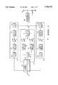
- FIG. 1shows a block diagram of a power amplifier in accordance with a preferred embodiment of the present invention.
- Amplifier 10includes input port 12 for receiving an RF input signal which could be amplitude or frequency modulated, or bauded such as quadrature phase shift keyed signal, or any combination of these, including multi-carrier input signals.
- Power divider 40coupled to input port 12, is a three-way equal amplitude power splitter, in the preferred embodiment. Equivalent partitioning of the input signal results in a -5 dB signal level at the outputs of each of the three power divider output ports.
- First carrier amplifier network 70comprises a phase shifter 42 for shifting the signal from first carrier amplifier output port an additional one-quarter wavelength.
- Phase shifter 42is preferably comprised of a transmission line of one-quarter wavelength in length at the operating frequency.
- Peak amplifier network 72comprises a phase shifter 20 for shifting the signal from the peak amplifier output port an additional one quarter wavelength.
- phase shifter 20further comprises a power splitter for providing an equal power split of the phase shifted signal from the peak amplifier output port of power divider 40.
- a power dividermay be one of the known types of power dividers such as a Wilkenson power divider. Both of outputs from the power divider/phase shifter 20 are equal in phase and -3 dB down in additional signal level for a total of -8 dB in signal level relative to the signal level at input port 12.
- Input matching networks 46, 48, 50, and 52impedance match the transmission lines with the input impedance of the corresponding amplifiers.
- phase shifter 16provides both a one-quarter wavelength phase shift and an impedance inverter or transforming network.
- phase shifter 16comprises a transmission line of one-quarter wavelength in length at the operating frequency. By phase shifting, the phase is aligned prior to combining all of the various outputs.
- phase shifter 24In second carrier amplifier network 74, output matching network 64 from second carrier amplifier 15 couples to a phase shifter 24 providing both a one-quarter wavelength phase shift and an impedance inverter or transforming network. As with phase shifter 16, phase shifter 24 comprises a transmission line of one-quarter wavelength in length at the operating frequency. Phase shifter 24 aligns the signal prior to combining.
- a task 310biases the first carrier amplifier to produce a first carrier amplifier output signal when the input signal has a low power level.
- Bias circuitsare known by those of skill in the art for setting an amplification threshold for the first carrier amplifier.
- a task 315phase shifts the signal having the low power level a quarter-wavelength to produce a first carrier amplifier input signal.
- Phase shiftersmay be a quarter-wavelength transmission line known by those of skill in the art.
- a task 340amplifies the second carrier amplifier input signal in a second carrier amplifier to produce a second carrier amplifier output signal.
- a query task 345determines if the second carrier amplifier is saturated. When the second carrier amplifier is not saturated, processing returns to task 335 where signals are continued to be phase shifted and efficiently amplified.
- a task 350biases the peak amplifier to produce the peak amplifier output signal when the signal has a high power level. It should be noted that biasing of each amplifier may be performed in parallel and in a hardware implementation, biasing of amplifiers is ongoing upon applying power to the circuit.
- any or all componentmay be built using lumped elements.
- the present inventionsequences the initialization of each respective power combining operation in such a manner as to optimize and improve on the high efficiency operating range achievable from the active devices when compared to the prior art.
Landscapes
- Engineering & Computer Science (AREA)
- Power Engineering (AREA)
- Amplifiers (AREA)
- Microwave Amplifiers (AREA)
Abstract
Description
This invention relates in general to the field of linear power amplifiers, and more particularly to microwave power amplifiers for signals having multiple carrier frequencies.
In satellite telecommunication systems, it is desirable for RF power amplifiers to linearly amplify RF signals in a highly efficient manner. However, there are tradeoffs between maximum efficiency and high linearity. Efficiency is generally proportional to input drive level, and high efficiency is usually not attained until an amplifier approaches its maximum output power, which is not consistent with linear operation. Doherty-type amplifiers, for example, achieve an efficiency advantage over standard class AB and class B amplifiers near peak power, in part, because of an instantaneous modulation of their carrier amplifier's loadline as the RF input level changes. In other words, Doherty-type amplifiers exhibit a more benign relationship between input drive level and efficiency because the amplifier's loadline is continuously modified to maintain high efficiency as input drive level changes. In addition, the bias power of Doherty-type amplifiers is greatly reduced over standard class AB and class B amplifiers.
High linearity is generally evidenced by a low level of non-linear intermodulation products. In many situations, the RF signals that need to be amplified in satellite telecommunication systems include multiple carrier frequencies spread over a large instantaneous bandwidth. The noise-like characteristics of these multiple-carrier signals make it difficult to amplify such signals in a linear fashion.
A key issue in operation of multi-carrier linear power amplifiers is the noise-like characteristic of the multiple carrier signals. In the case of single frequency linear power amplifiers, the power amplifier need only respond to constant or near constant envelopes. However, the RF amplitude envelope of noise-like multi-carrier signals changes in time according to the total occupied signal bandwidth. Multi-carrier linear power amplifiers should respond to this changing envelope in order to obtain high efficiency and linear operation. Therefore, there are additional network design requirements for multi-carrier linear power amplifiers above and beyond that of single frequency linear power amplifiers.
Thus what is needed is a multi-stage amplifier that improves the efficiency across a broader dynamic range than is possible with other amplifier configurations. What is also needed is an amplifier circuit that is suitable for applications, such as satellites, and portable transceivers that rely upon efficient power consumption techniques for feasible advanced communications. What is also needed is an amplifier circuit that is linear, efficient, has a low bias power level and is manufacturable.
The invention is pointed out with particularity in the appended claims. However, a more complete understanding of the present invention may be derived by referring to the detailed description and claims when considered in connection with the figures, wherein:
FIG. 1 shows a block diagram of a power amplifier in accordance with a preferred embodiment of the present invention;
FIG. 2 shows a graph of efficiency comparisons of a multi-stage power amplifier in accordance with a preferred embodiment of the present invention; and
FIG. 3 is a flowchart of a method of amplifying a signal in accordance with an embodiment of the present invention.
The exemplification set out herein illustrates a preferred embodiment of the invention in one form thereof, and such exemplification is not intended to be construed as limiting in any manner.
The present invention provides, among other things, a power amplifier that linearly amplifies noise-like multi-carrier signals over a wide range of power levels. The present invention also provides a low loss (i.e., good DC to RF efficiency) amplifier and method of amplification that achieves high DC to RF conversion efficiency over a wide range of input drive signal levels. Prior art amplifiers cannot simultaneously accomplish high efficiency and good linearity since their high efficiency point occurs when the amplifier is driven into saturation and the limiting process inherent to power saturated operation gives rise to significant intermodulation distortion products.
In the present invention, by using planar microstrip in a distributed topology, as opposed to lumped components, production costs are reduced and reliability improved due to fewer components, fewer wire bonds, and more manufacturably repeatable circuits.
FIG. 1 shows a block diagram of a power amplifier in accordance with a preferred embodiment of the present invention.Amplifier 10 includesinput port 12 for receiving an RF input signal which could be amplitude or frequency modulated, or bauded such as quadrature phase shift keyed signal, or any combination of these, including multi-carrier input signals.Power divider 40, coupled toinput port 12, is a three-way equal amplitude power splitter, in the preferred embodiment. Equivalent partitioning of the input signal results in a -5 dB signal level at the outputs of each of the three power divider output ports.Power divider 40, in the preferred embodiment, comprises two output ports, first carrier amplifier network port and second carrier amplifier network port, being in-phase with the input port and a third output port, peak amplifier network port, lagging the input port by a quarter of a wavelength due to aphase shifter 19. Each of the three power divider output ports distributes the input signal to a firstcarrier amplifier network 70, a secondcarrier amplifier network 74, and apeak amplifier network 72.
Firstcarrier amplifier network 70 comprises aphase shifter 42 for shifting the signal from first carrier amplifier output port an additional one-quarter wavelength.Phase shifter 42 is preferably comprised of a transmission line of one-quarter wavelength in length at the operating frequency.
Secondcarrier amplifier network 74 comprises aphase shifter 44 for shifting the signal from second carrier amplifier output port an additional one-quarter wavelength.Phase shifter 44 is preferably comprised of a transmission line of one-quarter wavelength in length at the operating frequency.
Referring back to firstcarrier amplifier network 70, afirst carrier amplifier 14 is biased, in the preferred embodiment, as a class AB and amplifies when an input signal is present.First carrier amplifier 14 amplifies in the presence of "low" signal levels even as other amplifiers are biased off.
Referring to secondcarrier amplifier network 74, asecond carrier amplifier 15 is biased as a class C and amplifies when an input signal higher than the minimum required forfirst carrier amplifier 14 is present.Second carrier amplifier 15 amplifies in the presence of "medium" signal levels such as at a level occurring whenfirst carrier amplifier 14 is reaching or has reached saturation.
Inpeak amplifier network 72, apeak amplifier 22 is biased to amplify "high" power level signals such as those that occur whensecond carrier amplifier 15 has been amplifying and is approaching or has reached saturation. In the preferred embodiment, apeak amplifier 23 may be configured in parallel withpeak amplifier 22 to provide additional signal power.
In the preferred embodiment,amplifiers first carrier amplifier 14 begins amplifying,second carrier amplifier 15 andpeak amplifiers Output matching networks
In firstcarrier amplifier network 70,output matching network 60 fromfirst carrier amplifier 14 couples to aphase shifter 16 providing both a one-quarter wavelength phase shift and an impedance inverter or transforming network. In the preferred embodiment,phase shifter 16 comprises a transmission line of one-quarter wavelength in length at the operating frequency. By phase shifting, the phase is aligned prior to combining all of the various outputs.
In secondcarrier amplifier network 74, output matching network 64 fromsecond carrier amplifier 15 couples to aphase shifter 24 providing both a one-quarter wavelength phase shift and an impedance inverter or transforming network. As withphase shifter 16,phase shifter 24 comprises a transmission line of one-quarter wavelength in length at the operating frequency.Phase shifter 24 aligns the signal prior to combining.
Inpeak amplifier network 72,output matching network 62 combines outputs from bothpeak amplifiers phase shifters combiner 28 are in-phase with each other and are driven to animpedance transformer 68 for matching with the load at anoutput 30. In the preferred embodiment, firstcarrier amplifier network 70, secondcarrier amplifier network 74, andpeak amplifier network 72 are combined in a parallel manner. Because of the parallel configuration of multi-stages, devices in each of these stages may be replicated and be on the order of the same size of devices and therefore not susceptible to being overdriven by larger devices. The similar sizing of devices also contributes to matching and replication of devices as layed-out in substrates such as microstrip.
The sequence of operation ofamplifier 10 is as follows.First carrier amplifier 14 is biased to amplify in the presence of an input RF signal with bothsecond carrier amplifier 15 andpeak amplifiers combiner 28.Second carrier amplifier 15 is biased such that asfirst carrier amplifier 14 approaches saturation,second carrier amplifier 15 turns on because of the increased input signal drive level. When operative,second carrier amplifier 15 augments the output drive level offirst carrier amplifier 14 as seen atoutput 30. An increased output voltage generated by operativesecond carrier amplifier 15 appears as an impedance increase atcombiner 28.
Oncesecond carrier amplifier 15 approaches saturation,peak amplifiers peak amplifiers operative peak amplifiers combiner 28 and is impedance matched to the load byimpedance transformer 68 to generateoutput 30.
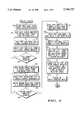
FIG. 2 shows a graph of efficiency comparisons of a multi-stage power amplifier in accordance with a preferred embodiment of the present invention. The graph shows a plot of RF output power and efficiency as a function of input RF power. A class F amplifier was analyzed and plotted as class F amplifiers are capable of efficiencies approaching 85%. Those skilled in the art recognize that class F amplifiers short circuit the even harmonics and open circuit the odd harmonics. Such conditioning generates a rectangular voltage waveform at the drain of active devices. Other classes of amplifiers could also be employed such as class E, class B, class C, and others known by those of skill in the art.
Aclass B curve 210 illustrates an ideal class B amplifier waveform depicting approximately linear efficiency. It should be noted that for small Vo/Vomax ratios, the efficiency levels are very low and linearly increase to a saturation point. However, through appropriate biasing, the slope of the gain may be adjusted to provide earlier saturation, thus improving the efficiency rate for smaller signals.
By adding additional stages, an amplifier curve may be adjusted to improve efficiencies over a broader range of input signal levels. A 2-stage Doherty curve 220 illustrates a first stage saturating at asaturation point 221 followed by an expected drop off in efficiency for an increase in Vo. As Vo increases, a second stage is biased to turn on and the efficiency begins to increase again to a second saturation point shown corresponding tosaturation point 211. The overall efficiency has been improved for a broader range of signals, however, low level input signals still result in low efficiency over low Vo signals.
To improve the overall efficiency ofamplifier 10 for multi-carrier input signals. Amulti-stage curve 230 illustrates an improvement by enhancing the amplifier efficiency for lower Vo/Vomax ratios. A first stage saturates at asaturation point 231 with the efficiency dropping off thereafter. As the Vo level increases, a second stage turns on and because it is not yet saturated, the efficiency of the overall multi-stage amplifier begins to improve as shown. As the second stage saturates atsaturation point 221, the overall efficiency of the multi-stage amplifier decreases and a subsequent third stage begins to turn on and recover the efficiency. In the present invention, the improvement in efficiency ofamplifier 10 is shown as the increase in area between 2-stage Doherty curve 220 andmulti-stage curve 230.
FIG. 3 is a flowchart of a method of amplifying a signal in accordance with an embodiment of the present invention. An amplify signal process amplifies signals having low, medium and high power levels to enhance the efficiency of overall performance of the amplifier.
Atask 305 power divides the input signal into three separate distribution paths to the first carrier amplifier, the second carrier amplifier, and the peak amplifier. This preferably is performed by a power divider circuit such as power divider 40 (FIG. 1).
Atask 310 biases the first carrier amplifier to produce a first carrier amplifier output signal when the input signal has a low power level. Bias circuits are known by those of skill in the art for setting an amplification threshold for the first carrier amplifier.
Atask 315 phase shifts the signal having the low power level a quarter-wavelength to produce a first carrier amplifier input signal. Phase shifters may be a quarter-wavelength transmission line known by those of skill in the art.
Atask 320 amplifies the first carrier amplifier input signal in the first carrier amplifier to produce a first carrier amplifier output signal. Aquery task 325 determines when the first carrier amplifier is saturated. When saturation has not yet occurred, amplification continues at an efficient level.
When saturation has occurred or is soon to occur, atask 330 biases the second carrier amplifier to produce the second carrier amplifier output signal when the signal has said medium level. Atask 335 phase shifts the signal having a medium power level of the signal a quarter-wavelength to produce a second carrier amplifier input signal.
Atask 340 amplifies the second carrier amplifier input signal in a second carrier amplifier to produce a second carrier amplifier output signal. Aquery task 345 determines if the second carrier amplifier is saturated. When the second carrier amplifier is not saturated, processing returns totask 335 where signals are continued to be phase shifted and efficiently amplified.
When the second carrier amplifier is saturated or nearly saturated, atask 350 biases the peak amplifier to produce the peak amplifier output signal when the signal has a high power level. It should be noted that biasing of each amplifier may be performed in parallel and in a hardware implementation, biasing of amplifiers is ongoing upon applying power to the circuit.
Atask 355 phase shifts the signal having the high power level of the input signal a half-wavelength to produce a peak amplifier input signal. Atask 360 amplifies the peak amplifier input signal in a peak amplifier to produce a peak amplifier output signal.
Atask 365 phase shifts the first carrier amplifier output signal and the second carrier amplifier output signal a quarter-wavelength to produce a shifted first carrier amplifier output signal and a shifted second carrier amplifier output signal. Atask 370 combines the shifted first carrier amplifier output signal, the shifted second carrier amplifier output signal, and the peak amplifier output signal to produce an output signal. Atask 375 produces a predetermined output impedance match for the first carrier amplifier, the second carrier amplifier, and the peak amplifier to provide an output signal to the load.
While the embodiments discussed above are preferably fabricated on Gallium Arsenide, any or all component may be built using lumped elements.
Thus a power amplifier has been described that is able to handle noise-like multi-carrier signals and is able to operate efficiently over a wide range of signal power levels. This power amplifier is suitable for use in portable devices requiring efficiency for prolonged performance. Such uses include portable telecommunications such as cellular telephones, and satellite communications employing multiple carrier frequencies spread over a large instantaneous bandwidth.
The present invention incorporates a topology that efficiently achieves the combined output power capable from four active devices. Typically, a 2-stage Doherty amplifier combines four devices together would have required power combiners with equal splits power combiners on the input and output of the two individual Doherty amplifiers. The present invention accomplishes the successful power combining of four active devices without the use of a power combiner to tie two individual Doherty amplifiers together, thus foregoing the circuit losses associated with passive power combiner.
Additionally, the present invention sequences the initialization of each respective power combining operation in such a manner as to optimize and improve on the high efficiency operating range achievable from the active devices when compared to the prior art.
Thus, a power amplifier circuit for amplifying signals comprising a first and second carrier amplifiers and a peak amplifiers has been disclosed. Also, a method for amplifying signals having a spectrum of input signal levels has been disclosed for improving the overall efficiency of a power amplifier.
The foregoing description of the specific embodiments will so fully reveal the general nature of the invention that others can, by applying current knowledge, readily modify and/or adapt for various applications such specific embodiments without departing from the generic concept, and therefore such adaptations and modifications should and are intended to be comprehended within the meaning and range of equivalents of the disclosed embodiments.
It is to be understood that the phraseology or terminology employed herein is for the purpose of description and not of limitation. Accordingly, the invention is intended to embrace all such alternatives, modifications, equivalents and variations as fall within the spirit and broad scope of the appended claims.
Claims (19)
1. A power amplifier, comprising:
a first carrier amplifier network including:
(a) a first carrier amplifier for amplifying input signals and producing first carrier signals;
(b) a first impedance transforming network coupled to an output of said first carrier amplifier;
(c) a first phase shifter coupled to said first impedance transforming network for phase shifting said first carrier signals one quarter wavelength; and
(d) a second phase shifter coupled to an input of said first carrier amplifier for phase shifting said input signals a quarter wavelength;
a second carrier amplifier network including:
(e) a second carrier amplifier for amplifying input signals and producing second carrier signals;
(f) a second impedance transforming network coupled to an output of said second carrier amplifier;
(g) a third phase shifter coupled to said second impedance transforming network for phase shifting said second carrier signals one quarter wavelength; and
(h) a fourth phase shifter coupled to an input of said second carrier amplifier for phase shifting said input signals a quarter wavelength;
a peak amplifier network including:
(i) a first peak amplifier for amplifying said input signals and producing peak signals;
and
(j) a fifth phase shifter coupled to an input of said first peak amplifier for phase shifting said input signals a half wavelength; and
a combiner for in-phase combining said first carrier signals, said second carrier signals, and said peak signals to produce an output signal.
2. The power amplifier as claimed in claim 1 wherein said first carrier amplifier is configured to provide amplification of said input signals at low power levels, and wherein said second carrier amplifier is biased to provide amplification of said input signals at medium power levels, and wherein said first peak amplifier is biased to provide amplification of said input signals at high power levels.
3. The power amplifier as claimed in claim 2 wherein said medium power levels coincide with saturation of said first carrier amplifier and said high power levels coincide with saturation of said second carrier amplifier.
4. The power amplifier as claimed in claim 1 wherein said peak amplifier network further comprises a second peak amplifier coupled in parallel with said first peak amplifier for further producing said peak signals.
5. The power amplifier as claimed in claim 1 wherein said fifth phase shifter is comprised of a sixth phase shifter and a seventh phase shifter.
6. The power amplifier as claimed in claim 5, further comprising a power divider for dividing said input signals for in-phase distribution to said first carrier amplifier network, and said second carrier amplifier network, and for phase-shifted distribution to said sixth phase shifter in said peak amplifier network.
7. The power amplifier as claimed in claim 1 wherein said combiner comprises a reactive combiner.
8. The power amplifier as claimed in claim 1, further comprising output matching circuits coupled between said first carrier amplifier, said second carrier amplifier, said first peak amplifier and said first impedance transforming network, said second impedance transforming network, said combiner, respectively, said output matching circuits for providing impedance matching of said first carrier amplifier network, said second carrier amplifier network, and said peak amplifier network.
9. The power amplifier as claimed in claim 8, wherein said output matching circuits are comprised of parallel coupled microstrip lines.
10. A power amplifier, comprising:
a first carrier amplifier configured to amplify low signal levels of a quarter-wavelength phase shifted input signal;
a first quarter-wavelength transmission line coupled to the output of said first carrier amplifier;
a second carrier amplifier configured to amplify medium signal levels of said quarter-wavelength phase shifted input signal;
a second quarter-wavelength transmission line coupled to the output of said second carrier amplifier;
a peak amplifier configured to amplify high signal levels of a half-wavelength phase shifted input signal; and
a combiner for in-phase combining output signals of said first and second quarter-wavelength transmission lines and said peak amplifier.
11. The power amplifier as recited in claim 10, further comprising:
a first biasing means for configuring said first carrier amplifier to produce a first carrier amplifier output signal from said low signal levels;
a second biasing means for configuring said second carrier amplifier to produce a second carrier amplifier output signal from said medium signal levels; and
a peak biasing means for configuring said peak amplifier to produce a peak amplifier output signal from said high signal levels.
12. The power amplifier as recited in claim 10, further comprising a power divider for dividing an input signal into three separate paths distribution to said first carrier amplifier, said second carrier amplifier, and said peak amplifier.
13. The power amplifier as recited in claim 10, further comprising an output impedance matching means coupled between outputs of said first carrier amplifier, said second carrier amplifier, said peak amplifier and said combiner for matching impedances of said first carrier amplifier output signal, said second carrier amplifier output signal, and said peak amplifier output signal.
14. A method of amplifying a signal of low, medium, and high power level, comprising the steps of:
phase shifting said signal having said low power level a quarter-wavelength to produce a first carrier amplifier input signal;
amplifying said first carrier amplifier input signal in a first carrier amplifier to produce a first carrier amplifier output signal;
phase shifting said signal having said medium power level a quarter-wavelength to produce a second carrier amplifier input signal;
amplifying said second carrier amplifier input signal in a second carrier amplifier to produce a second carrier amplifier output signal;
phase shifting said signal having said high power level a half-wavelength to produce a peak amplifier input signal;
amplifying said peak amplifier input signal in a peak amplifier to produce a peak amplifier output signal;
phase shifting said first carrier amplifier output signal and said second carrier amplifier output signal a quarter-wavelength to produce a shifted first carrier amplifier output signal and a shifted second carrier amplifier output signal; and
combining said shifted first and second carrier amplifier output signals, and said peak amplifier output signal to produce an output signal.
15. The method as recited in claim 14, further comprising the steps of:
biasing said first carrier amplifier to produce said first carrier amplifier output signal for said low power level;
biasing said second carrier amplifier to produce said second carrier amplifier output signal for said medium power level; and
biasing said peak amplifier to produce said peak amplifier output signal for said high power level.
16. The method as recited in claim 15, further comprising the steps of:
prior to said amplifying said second carrier amplifier input signal step, saturating said first carrier amplifier; and
prior to said amplifying said peak amplifier input signal step, saturating said second carrier amplifier.
17. The method as recited in claim 16 further comprising the step of power dividing said signal into three separate distribution paths to said first carrier amplifier, said second carrier amplifier, and said peak amplifier.
18. The method as recited in claim 14, further comprising the step of producing a predetermined output impedance match for said first carrier amplifier, said second carrier amplifier, and said peak amplifier.
19. The method as recited in claim 14, wherein said amplifying said peak amplifier input signal step further comprises the step of providing a second peak amplifier for augmenting said peak amplifier output signal.
Priority Applications (7)
| Application Number | Priority Date | Filing Date | Title |
|---|---|---|---|
| US08/730,045US5786727A (en) | 1996-10-15 | 1996-10-15 | Multi-stage high efficiency linear power amplifier and method therefor |
| PCT/US1997/014392WO1998016997A1 (en) | 1996-10-15 | 1997-08-13 | Multi-stage high efficiency linear power amplifier |
| EP97938340AEP0932933B1 (en) | 1996-10-15 | 1997-08-13 | Multi-stage high efficiency linear power amplifier |
| DE69729466TDE69729466T2 (en) | 1996-10-15 | 1997-08-13 | MULTI-STAGE LINEAR PERFORMANCE AMPLIFIER WITH HIGH EFFICIENCY |
| JP51831898AJP4027988B2 (en) | 1996-10-15 | 1997-08-13 | Multistage high efficiency linear power amplifier and method |
| TW086113116ATW399362B (en) | 1996-10-15 | 1997-09-10 | Multi-stage high efficiency linear power amplifier and method therefor |
| KR1019997003362AKR100306722B1 (en) | 1996-10-15 | 1999-04-14 | Multi-stage high efficiency linear power amplifier |
Applications Claiming Priority (1)
| Application Number | Priority Date | Filing Date | Title |
|---|---|---|---|
| US08/730,045US5786727A (en) | 1996-10-15 | 1996-10-15 | Multi-stage high efficiency linear power amplifier and method therefor |
Publications (1)
| Publication Number | Publication Date |
|---|---|
| US5786727Atrue US5786727A (en) | 1998-07-28 |
Family
ID=24933681
Family Applications (1)
| Application Number | Title | Priority Date | Filing Date |
|---|---|---|---|
| US08/730,045Expired - LifetimeUS5786727A (en) | 1996-10-15 | 1996-10-15 | Multi-stage high efficiency linear power amplifier and method therefor |
Country Status (7)
| Country | Link |
|---|---|
| US (1) | US5786727A (en) |
| EP (1) | EP0932933B1 (en) |
| JP (1) | JP4027988B2 (en) |
| KR (1) | KR100306722B1 (en) |
| DE (1) | DE69729466T2 (en) |
| TW (1) | TW399362B (en) |
| WO (1) | WO1998016997A1 (en) |
Cited By (102)
| Publication number | Priority date | Publication date | Assignee | Title |
|---|---|---|---|---|
| US5986500A (en)* | 1996-12-30 | 1999-11-16 | Samsung Electronics Co., Ltd. | Combined linear power amplifying device and method |
| US5999046A (en)* | 1998-06-10 | 1999-12-07 | Motorola, Inc. | Power combiner for use in a radio frequency system and a method of constructing a power combiner |
| US6262629B1 (en) | 1999-07-06 | 2001-07-17 | Motorola, Inc. | High efficiency power amplifier having reduced output matching networks for use in portable devices |
| US6320462B1 (en)* | 2000-04-12 | 2001-11-20 | Raytheon Company | Amplifier circuit |
| US6329877B1 (en)* | 1999-06-25 | 2001-12-11 | Agere Systems Guardian Corp. | Efficient power amplifier |
| WO2001095481A1 (en)* | 2000-06-06 | 2001-12-13 | Telefonaktiebolaget Lm Ericsson | Multistage doherty amplifier |
| US6384680B1 (en)* | 2000-01-19 | 2002-05-07 | Hitachi, Ltd. | RF amplifier with plural combiners |
| US6469581B1 (en) | 2001-06-08 | 2002-10-22 | Trw Inc. | HEMT-HBT doherty microwave amplifier |
| US6472934B1 (en)* | 2000-12-29 | 2002-10-29 | Ericsson Inc. | Triple class E Doherty amplifier topology for high efficiency signal transmitters |
| US20020186078A1 (en)* | 2001-06-08 | 2002-12-12 | Kobayashi Kevin W. | Application of the doherty amplifier as a predistortion circuit for linearizing microwave amplifiers |
| WO2002054581A3 (en)* | 2000-12-29 | 2003-01-30 | Ericsson Inc | Class e doherty amplifier topology for high efficiency signal transmitters |
| US6587511B2 (en) | 2001-01-26 | 2003-07-01 | Intel Corporation | Radio frequency transmitter and methods thereof |
| US20030123566A1 (en)* | 2001-12-27 | 2003-07-03 | Jaime Hasson | Transmitter having a sigma-delta modulator with a non-uniform polar quantizer and methods thereof |
| US20030125065A1 (en)* | 2001-12-27 | 2003-07-03 | Ilan Barak | Method and apparatus for generating an output signal |
| US20030137346A1 (en)* | 2000-07-07 | 2003-07-24 | Richard Hellberg | Transmitter including a composite amplifier |
| EP1032120A3 (en)* | 1999-02-26 | 2003-07-30 | Matsushita Electric Industrial Co., Ltd. | Power amplifier, power control method for power amplifier, and communication equipment |
| WO2003065573A1 (en)* | 2002-01-28 | 2003-08-07 | Cree Microwave, Inc. | N-way rf power amplifier with increased backoff power and power added efficiency |
| US6617929B2 (en)* | 2001-03-21 | 2003-09-09 | Postech Foundation | Full output matching apparatus of a microwave doherty amplifier |
| US20030201833A1 (en)* | 2002-01-28 | 2003-10-30 | Cree Microwave, Inc. | N-way RF power amplifier circuit with increased back-off capability and power added efficiency using unequal input power division |
| US20030210096A1 (en)* | 2002-01-28 | 2003-11-13 | Cree Microwave, Inc. | N-way RF power amplifier circuit with increased back-off capability and power added efficiency using selected phase lengths and output impedances |
| US6674323B2 (en)* | 2001-09-11 | 2004-01-06 | Renesas Technology Corporation | High frequency power amplifier, high frequency power amplifier module, and portable telephone |
| US20040041627A1 (en)* | 2002-08-29 | 2004-03-04 | Pohang University Of Science And Technology Foundation | Doherty amplifier |
| GB2393866A (en)* | 2002-09-06 | 2004-04-07 | Filtronic Plc | A class F Doherty amplifier using PHEMTs |
| US20040075503A1 (en)* | 2000-12-15 | 2004-04-22 | Naoki Komatsu | Power amplifier and communication apparatus |
| US6744312B2 (en) | 2001-03-06 | 2004-06-01 | Andrew Corporation | Adaptive power amplifier system |
| US20040145416A1 (en)* | 2002-02-01 | 2004-07-29 | Youngwoo Kwon | High linearity doherty communication amplifier with integrated output matching unit |
| US20040185916A1 (en)* | 2003-03-18 | 2004-09-23 | Chang Shiaw W. | Load variation tolerant radio frequency (RF) amplifier |
| US6825719B1 (en) | 2000-05-26 | 2004-11-30 | Intel Corporation | RF power amplifier and methods for improving the efficiency thereof |
| WO2005031966A1 (en)* | 2003-09-26 | 2005-04-07 | Telefonaktiebolaget Lm Ericsson | Composite power amplifier |
| US20050129142A1 (en)* | 2003-12-15 | 2005-06-16 | Daniel Yellin | Filter for a modulator and methods thereof |
| US20050136864A1 (en)* | 2003-12-17 | 2005-06-23 | Eliav Zipper | Radio frequency modulator and methods thereof |
| WO2005088830A1 (en)* | 2004-03-13 | 2005-09-22 | Filtronic Plc | A doherty amplifier |
| US20050227644A1 (en)* | 2004-04-09 | 2005-10-13 | Nikolai Maslennikov | Constant gain nonlinear envelope tracking high efficiency linear amplifier |
| US20050242875A1 (en)* | 2004-03-19 | 2005-11-03 | Mark Gurvich | High efficiency linear amplifier employing dynamically controlled back off |
| US20050248401A1 (en)* | 2002-09-06 | 2005-11-10 | Richard Hellberg | Composite power amplifier |
| US20050280466A1 (en)* | 2004-06-21 | 2005-12-22 | Gailus Paul H | Method and apparatus for an enhanced efficiency power amplifier |
| US20060087371A1 (en)* | 2004-10-26 | 2006-04-27 | Andrew Corporation | High efficiency amplifier |
| US20060103466A1 (en)* | 2004-11-18 | 2006-05-18 | Shah Tushar R | High efficiency doherty amplifier with a segmented main amplifier |
| GB2421130A (en)* | 2004-12-13 | 2006-06-14 | Toshiba Kk | A Doherty amplifier with feedback control of gain and phase |
| US20060214732A1 (en)* | 2005-03-24 | 2006-09-28 | Cree Microwave, Inc. | High power Doherty amplifier using multi-stage modules |
| US20060267689A1 (en)* | 2005-05-24 | 2006-11-30 | Intel Corporation | Parallel power amplifier apparatus, method, and system |
| US20060286097A1 (en)* | 1995-03-31 | 2006-12-21 | Xenova Research Ltd. | Hapten-carrier conjugates for use in drug-abuse therapy and methods for preparation of same |
| US7184723B2 (en) | 2004-10-22 | 2007-02-27 | Parkervision, Inc. | Systems and methods for vector power amplification |
| US20070126502A1 (en)* | 2005-12-01 | 2007-06-07 | Louis Edward V | High gain, high efficiency power amplifier |
| US20070135065A1 (en)* | 2005-12-13 | 2007-06-14 | Andrew Corporation | Predistortion system and amplifier for addressing group delay modulation |
| US20070146094A1 (en)* | 2000-07-20 | 2007-06-28 | Cornelis Frederik Du Toit | Tunable microwave devices with auto-adjusting matching circuit |
| US20070197180A1 (en)* | 2006-01-14 | 2007-08-23 | Mckinzie William E Iii | Adaptive impedance matching module (AIMM) control architectures |
| US20070247217A1 (en)* | 2006-04-24 | 2007-10-25 | Sorrells David F | Systems and methods of rf power transmission, modulation, and amplification, including embodiments for amplifier class transitioning |
| US20070285326A1 (en)* | 2006-01-14 | 2007-12-13 | Mckinzie William E | Adaptively tunable antennas incorporating an external probe to monitor radiated power |
| US20080036533A1 (en)* | 2006-08-11 | 2008-02-14 | Lg-Nortel Co., Ltd. | Multi-path doherty amplifier and control method of a multi-path doherty amplifier |
| US7336753B2 (en) | 2003-06-26 | 2008-02-26 | Marvell International Ltd. | Transmitter |
| US20080106349A1 (en)* | 2006-11-08 | 2008-05-08 | Mckinzie William E | Adaptive impedance matching apparatus, system and method |
| US20080136714A1 (en)* | 2006-12-12 | 2008-06-12 | Daniel Boire | Antenna tuner with zero volts impedance fold back |
| KR100858063B1 (en)* | 2004-03-13 | 2008-09-10 | 필트로닉 피엘씨 | Doherty Amplifier |
| US20090039976A1 (en)* | 2006-11-08 | 2009-02-12 | Mckinzie Iii William E | Adaptive impedance matching apparatus,system and method with improved dynamic range |
| US7620129B2 (en) | 2007-01-16 | 2009-11-17 | Parkervision, Inc. | RF power transmission, modulation, and amplification, including embodiments for generating vector modulation control signals |
| US20100033243A1 (en)* | 2007-04-20 | 2010-02-11 | Fujitsu Limited | Amplifying Apparatus |
| US20100090760A1 (en)* | 2008-10-14 | 2010-04-15 | Paratek Microwave, Inc. | Low-distortion voltage variable capacitor assemblies |
| US7885682B2 (en) | 2006-04-24 | 2011-02-08 | Parkervision, Inc. | Systems and methods of RF power transmission, modulation, and amplification, including architectural embodiments of same |
| US7911272B2 (en) | 2007-06-19 | 2011-03-22 | Parkervision, Inc. | Systems and methods of RF power transmission, modulation, and amplification, including blended control embodiments |
| US20110080215A1 (en)* | 2009-04-14 | 2011-04-07 | Wuhan Gewei Electronic Technology Co., Ltd. | Final stage three-way power combining amplifying circuit applied to power amplifier of mobile communications base station system |
| US20110140783A1 (en)* | 2009-12-15 | 2011-06-16 | Nxp B.V. | Doherty amplifier with composed transfer characteristic having multiple peak amplifiers |
| US7991363B2 (en) | 2007-11-14 | 2011-08-02 | Paratek Microwave, Inc. | Tuning matching circuits for transmitter and receiver bands as a function of transmitter metrics |
| US8013675B2 (en) | 2007-06-19 | 2011-09-06 | Parkervision, Inc. | Combiner-less multiple input single output (MISO) amplification with blended control |
| US8031804B2 (en) | 2006-04-24 | 2011-10-04 | Parkervision, Inc. | Systems and methods of RF tower transmission, modulation, and amplification, including embodiments for compensating for waveform distortion |
| US8072285B2 (en) | 2008-09-24 | 2011-12-06 | Paratek Microwave, Inc. | Methods for tuning an adaptive impedance matching network with a look-up table |
| US8213886B2 (en) | 2007-05-07 | 2012-07-03 | Paratek Microwave, Inc. | Hybrid techniques for antenna retuning utilizing transmit and receive power information |
| US8299867B2 (en) | 2006-11-08 | 2012-10-30 | Research In Motion Rf, Inc. | Adaptive impedance matching module |
| US8315336B2 (en) | 2007-05-18 | 2012-11-20 | Parkervision, Inc. | Systems and methods of RF power transmission, modulation, and amplification, including a switching stage embodiment |
| US8325097B2 (en) | 2006-01-14 | 2012-12-04 | Research In Motion Rf, Inc. | Adaptively tunable antennas and method of operation therefore |
| US8334722B2 (en) | 2007-06-28 | 2012-12-18 | Parkervision, Inc. | Systems and methods of RF power transmission, modulation and amplification |
| US8432234B2 (en) | 2010-11-08 | 2013-04-30 | Research In Motion Rf, Inc. | Method and apparatus for tuning antennas in a communication device |
| US8472888B2 (en) | 2009-08-25 | 2013-06-25 | Research In Motion Rf, Inc. | Method and apparatus for calibrating a communication device |
| US8594584B2 (en) | 2011-05-16 | 2013-11-26 | Blackberry Limited | Method and apparatus for tuning a communication device |
| US8620236B2 (en) | 2007-04-23 | 2013-12-31 | Blackberry Limited | Techniques for improved adaptive impedance matching |
| US8626083B2 (en) | 2011-05-16 | 2014-01-07 | Blackberry Limited | Method and apparatus for tuning a communication device |
| CN103580623A (en)* | 2012-08-10 | 2014-02-12 | 中兴通讯股份有限公司 | Radiofrequency power amplifier device and radiofrequency power amplifying method |
| US8655286B2 (en) | 2011-02-25 | 2014-02-18 | Blackberry Limited | Method and apparatus for tuning a communication device |
| US8693963B2 (en) | 2000-07-20 | 2014-04-08 | Blackberry Limited | Tunable microwave devices with auto-adjusting matching circuit |
| US8712340B2 (en) | 2011-02-18 | 2014-04-29 | Blackberry Limited | Method and apparatus for radio antenna frequency tuning |
| US8755454B2 (en) | 2011-06-02 | 2014-06-17 | Parkervision, Inc. | Antenna control |
| USRE44998E1 (en) | 2000-07-20 | 2014-07-08 | Blackberry Limited | Optimized thin film capacitors |
| US8803631B2 (en) | 2010-03-22 | 2014-08-12 | Blackberry Limited | Method and apparatus for adapting a variable impedance network |
| US8860526B2 (en) | 2010-04-20 | 2014-10-14 | Blackberry Limited | Method and apparatus for managing interference in a communication device |
| US8948889B2 (en) | 2012-06-01 | 2015-02-03 | Blackberry Limited | Methods and apparatus for tuning circuit components of a communication device |
| US9026062B2 (en) | 2009-10-10 | 2015-05-05 | Blackberry Limited | Method and apparatus for managing operations of a communication device |
| US9106316B2 (en) | 2005-10-24 | 2015-08-11 | Parkervision, Inc. | Systems and methods of RF power transmission, modulation, and amplification |
| US9246223B2 (en) | 2012-07-17 | 2016-01-26 | Blackberry Limited | Antenna tuning for multiband operation |
| US9350405B2 (en) | 2012-07-19 | 2016-05-24 | Blackberry Limited | Method and apparatus for antenna tuning and power consumption management in a communication device |
| US9362891B2 (en) | 2012-07-26 | 2016-06-07 | Blackberry Limited | Methods and apparatus for tuning a communication device |
| US9374113B2 (en) | 2012-12-21 | 2016-06-21 | Blackberry Limited | Method and apparatus for adjusting the timing of radio antenna tuning |
| US9406444B2 (en) | 2005-11-14 | 2016-08-02 | Blackberry Limited | Thin film capacitors |
| US9413066B2 (en) | 2012-07-19 | 2016-08-09 | Blackberry Limited | Method and apparatus for beam forming and antenna tuning in a communication device |
| US9608677B2 (en) | 2005-10-24 | 2017-03-28 | Parker Vision, Inc | Systems and methods of RF power transmission, modulation, and amplification |
| US9769826B2 (en) | 2011-08-05 | 2017-09-19 | Blackberry Limited | Method and apparatus for band tuning in a communication device |
| US9853363B2 (en) | 2012-07-06 | 2017-12-26 | Blackberry Limited | Methods and apparatus to control mutual coupling between antennas |
| US10003393B2 (en) | 2014-12-16 | 2018-06-19 | Blackberry Limited | Method and apparatus for antenna selection |
| US10278131B2 (en) | 2013-09-17 | 2019-04-30 | Parkervision, Inc. | Method, apparatus and system for rendering an information bearing function of time |
| US10404295B2 (en) | 2012-12-21 | 2019-09-03 | Blackberry Limited | Method and apparatus for adjusting the timing of radio antenna tuning |
| EP3780387A1 (en)* | 2019-08-15 | 2021-02-17 | NXP USA, Inc. | Integrated multiple-path power amplifier with interdigitated transistors |
| US10951172B2 (en)* | 2016-06-28 | 2021-03-16 | Telefonaktiebolaget Lm Ericsson (Publ) | Linear doherty power amplifier |
| US12413186B2 (en)* | 2021-03-10 | 2025-09-09 | Ohio State Innovation Foundation | 3-way dual-band Doherty power amplifier |
Families Citing this family (11)
| Publication number | Priority date | Publication date | Assignee | Title |
|---|---|---|---|---|
| SG90712A1 (en)* | 1998-12-05 | 2002-08-20 | Inst Of Microelectronics | Power amplifier |
| KR20020009676A (en)* | 2000-07-26 | 2002-02-02 | 윤종용 | Two path amplifier device using switch |
| JP4715994B2 (en)* | 2004-08-26 | 2011-07-06 | 日本電気株式会社 | Doherty amplifier parallel operation circuit |
| EP2159912A1 (en)* | 2008-08-29 | 2010-03-03 | Alcatel, Lucent | Multi-band Doherty amplifier |
| KR101094050B1 (en) | 2009-07-23 | 2011-12-19 | 성균관대학교산학협력단 | Dynamic Bias Supply with Multiple Switches |
| EP2490329B1 (en)* | 2009-10-13 | 2018-08-29 | Nec Corporation | Power amplifier and method for operating same |
| CN103199798B (en)* | 2013-03-20 | 2015-12-02 | 华为技术有限公司 | A kind of Doherty amplifying circuit and power amplifier |
| DK3205016T3 (en)* | 2014-10-06 | 2021-01-11 | Ericsson Telefon Ab L M | Amplifier circuit and procedure |
| JP2018085635A (en)* | 2016-11-24 | 2018-05-31 | 株式会社村田製作所 | Power amplifier |
| CN115913123A (en)* | 2021-09-23 | 2023-04-04 | 中兴通讯股份有限公司 | Power amplifier, power amplification method and electronic device |
| CN114142813B (en)* | 2021-12-07 | 2024-11-08 | 东南大学 | A millimeter-wave Doherty power amplifier chip based on a quasi-elliptical low-pass filter structure |
Citations (1)
| Publication number | Priority date | Publication date | Assignee | Title |
|---|---|---|---|---|
| US3579136A (en)* | 1965-12-13 | 1971-05-18 | George A Machamer | Multi-stage power amplifier in which each stage conducts for only a predetermined portion of the input |
Family Cites Families (7)
| Publication number | Priority date | Publication date | Assignee | Title |
|---|---|---|---|---|
| US5025225A (en)* | 1989-12-15 | 1991-06-18 | Raytheon Company | Amplifier having substantially constant D.C. to r.f. conversion efficiency |
| JPH0495409A (en)* | 1990-08-13 | 1992-03-27 | Fujitsu Ltd | Amplifier |
| US5101171A (en)* | 1990-11-23 | 1992-03-31 | Advanced Systems Research, Inc. | Extended bandwidth RF amplifier |
| JPH06252657A (en)* | 1993-02-22 | 1994-09-09 | Sumitomo Electric Ind Ltd | Low distortion amplifier |
| JPH06252658A (en)* | 1993-02-22 | 1994-09-09 | Sumitomo Electric Ind Ltd | Broad band low distortion amplifier |
| US5543751A (en)* | 1995-07-21 | 1996-08-06 | Motorola, Inc. | Power combiner for use in a radio frequency system and a method of constructing a power combiner |
| KR19980701804A (en)* | 1995-11-30 | 1998-06-25 | 안쏘니 제이. 살리,주니어 | Amplifier circuit and amplifier circuit tuning method |
- 1996
- 1996-10-15USUS08/730,045patent/US5786727A/ennot_activeExpired - Lifetime
- 1997
- 1997-08-13WOPCT/US1997/014392patent/WO1998016997A1/enactiveIP Right Grant
- 1997-08-13EPEP97938340Apatent/EP0932933B1/ennot_activeExpired - Lifetime
- 1997-08-13DEDE69729466Tpatent/DE69729466T2/ennot_activeExpired - Lifetime
- 1997-08-13JPJP51831898Apatent/JP4027988B2/ennot_activeExpired - Fee Related
- 1997-09-10TWTW086113116Apatent/TW399362B/ennot_activeIP Right Cessation
- 1999
- 1999-04-14KRKR1019997003362Apatent/KR100306722B1/ennot_activeExpired - Fee Related
Patent Citations (1)
| Publication number | Priority date | Publication date | Assignee | Title |
|---|---|---|---|---|
| US3579136A (en)* | 1965-12-13 | 1971-05-18 | George A Machamer | Multi-stage power amplifier in which each stage conducts for only a predetermined portion of the input |
Non-Patent Citations (2)
| Title |
|---|
| "Efficiency of Doherty RF-Power Amplifier Systems" by Frederick H. Raab, Ph.D., from Green Mountain Radio Research Company, (Aug. 4, 1984). |
| Efficiency of Doherty RF Power Amplifier Systems by Frederick H. Raab, Ph.D., from Green Mountain Radio Research Company, (Aug. 4, 1984).* |
Cited By (291)
| Publication number | Priority date | Publication date | Assignee | Title |
|---|---|---|---|---|
| US20060286097A1 (en)* | 1995-03-31 | 2006-12-21 | Xenova Research Ltd. | Hapten-carrier conjugates for use in drug-abuse therapy and methods for preparation of same |
| US5986500A (en)* | 1996-12-30 | 1999-11-16 | Samsung Electronics Co., Ltd. | Combined linear power amplifying device and method |
| US5999046A (en)* | 1998-06-10 | 1999-12-07 | Motorola, Inc. | Power combiner for use in a radio frequency system and a method of constructing a power combiner |
| EP1032120A3 (en)* | 1999-02-26 | 2003-07-30 | Matsushita Electric Industrial Co., Ltd. | Power amplifier, power control method for power amplifier, and communication equipment |
| US6329877B1 (en)* | 1999-06-25 | 2001-12-11 | Agere Systems Guardian Corp. | Efficient power amplifier |
| US6262629B1 (en) | 1999-07-06 | 2001-07-17 | Motorola, Inc. | High efficiency power amplifier having reduced output matching networks for use in portable devices |
| US6750707B2 (en) | 2000-01-19 | 2004-06-15 | Hitachi, Ltd. | Multi-carrier RF amplifiers |
| US6384680B1 (en)* | 2000-01-19 | 2002-05-07 | Hitachi, Ltd. | RF amplifier with plural combiners |
| US6320462B1 (en)* | 2000-04-12 | 2001-11-20 | Raytheon Company | Amplifier circuit |
| WO2001080420A3 (en)* | 2000-04-12 | 2002-07-04 | Raytheon Co | Amplifier circuit |
| US6825719B1 (en) | 2000-05-26 | 2004-11-30 | Intel Corporation | RF power amplifier and methods for improving the efficiency thereof |
| WO2001095481A1 (en)* | 2000-06-06 | 2001-12-13 | Telefonaktiebolaget Lm Ericsson | Multistage doherty amplifier |
| US20030137346A1 (en)* | 2000-07-07 | 2003-07-24 | Richard Hellberg | Transmitter including a composite amplifier |
| US6940349B2 (en)* | 2000-07-07 | 2005-09-06 | Telefonaktiebolaget Lm Ericsson (Publ) | Transmitter including a composite amplifier |
| US9768752B2 (en) | 2000-07-20 | 2017-09-19 | Blackberry Limited | Tunable microwave devices with auto-adjusting matching circuit |
| US20080169874A1 (en)* | 2000-07-20 | 2008-07-17 | Cornelis Frederik Du Toit | Tunable microwave devices with auto-adjusting matching circuit |
| US20080169880A1 (en)* | 2000-07-20 | 2008-07-17 | Cornelis Frederik Du Toit | Tunable microwave devices with auto-adjusting matching circuit |
| US8744384B2 (en) | 2000-07-20 | 2014-06-03 | Blackberry Limited | Tunable microwave devices with auto-adjusting matching circuit |
| US9948270B2 (en) | 2000-07-20 | 2018-04-17 | Blackberry Limited | Tunable microwave devices with auto-adjusting matching circuit |
| USRE44998E1 (en) | 2000-07-20 | 2014-07-08 | Blackberry Limited | Optimized thin film capacitors |
| US20070146094A1 (en)* | 2000-07-20 | 2007-06-28 | Cornelis Frederik Du Toit | Tunable microwave devices with auto-adjusting matching circuit |
| US7728693B2 (en)* | 2000-07-20 | 2010-06-01 | Paratek Microwave, Inc. | Tunable microwave devices with auto-adjusting matching circuit |
| US8896391B2 (en) | 2000-07-20 | 2014-11-25 | Blackberry Limited | Tunable microwave devices with auto-adjusting matching circuit |
| US7714678B2 (en)* | 2000-07-20 | 2010-05-11 | Paratek Microwave, Inc. | Tunable microwave devices with auto-adjusting matching circuit |
| US8693963B2 (en) | 2000-07-20 | 2014-04-08 | Blackberry Limited | Tunable microwave devices with auto-adjusting matching circuit |
| US7969257B2 (en)* | 2000-07-20 | 2011-06-28 | Paratek Microwave, Inc. | Tunable microwave devices with auto-adjusting matching circuit |
| US9431990B2 (en) | 2000-07-20 | 2016-08-30 | Blackberry Limited | Tunable microwave devices with auto-adjusting matching circuit |
| US20080169879A1 (en)* | 2000-07-20 | 2008-07-17 | Cornelis Frederik Du Toit | Tunable microwave devices with auto-adjusting matching circuit |
| US7795990B2 (en) | 2000-07-20 | 2010-09-14 | Paratek Microwave, Inc. | Tunable microwave devices with auto-adjusting matching circuit |
| US20040075503A1 (en)* | 2000-12-15 | 2004-04-22 | Naoki Komatsu | Power amplifier and communication apparatus |
| US6960959B2 (en)* | 2000-12-15 | 2005-11-01 | Matsushita Electric Industrial Co., Ltd. | Power amplifier and communication apparatus |
| WO2002054581A3 (en)* | 2000-12-29 | 2003-01-30 | Ericsson Inc | Class e doherty amplifier topology for high efficiency signal transmitters |
| WO2002054589A3 (en)* | 2000-12-29 | 2003-03-27 | Ericsson Inc | Triple class e doherty amplifier topology for high efficiency signal transmitters |
| US6472934B1 (en)* | 2000-12-29 | 2002-10-29 | Ericsson Inc. | Triple class E Doherty amplifier topology for high efficiency signal transmitters |
| US20030210751A1 (en)* | 2001-01-26 | 2003-11-13 | Ilan Barak | Radio frequency transmitter and methods thereof |
| US6587511B2 (en) | 2001-01-26 | 2003-07-01 | Intel Corporation | Radio frequency transmitter and methods thereof |
| US6744312B2 (en) | 2001-03-06 | 2004-06-01 | Andrew Corporation | Adaptive power amplifier system |
| US6617929B2 (en)* | 2001-03-21 | 2003-09-09 | Postech Foundation | Full output matching apparatus of a microwave doherty amplifier |
| US6864742B2 (en) | 2001-06-08 | 2005-03-08 | Northrop Grumman Corporation | Application of the doherty amplifier as a predistortion circuit for linearizing microwave amplifiers |
| US20020186078A1 (en)* | 2001-06-08 | 2002-12-12 | Kobayashi Kevin W. | Application of the doherty amplifier as a predistortion circuit for linearizing microwave amplifiers |
| US6469581B1 (en) | 2001-06-08 | 2002-10-22 | Trw Inc. | HEMT-HBT doherty microwave amplifier |
| US6674323B2 (en)* | 2001-09-11 | 2004-01-06 | Renesas Technology Corporation | High frequency power amplifier, high frequency power amplifier module, and portable telephone |
| US20030125065A1 (en)* | 2001-12-27 | 2003-07-03 | Ilan Barak | Method and apparatus for generating an output signal |
| US20030123566A1 (en)* | 2001-12-27 | 2003-07-03 | Jaime Hasson | Transmitter having a sigma-delta modulator with a non-uniform polar quantizer and methods thereof |
| WO2003065573A1 (en)* | 2002-01-28 | 2003-08-07 | Cree Microwave, Inc. | N-way rf power amplifier with increased backoff power and power added efficiency |
| CN100431264C (en)* | 2002-01-28 | 2008-11-05 | 克里微波有限责任公司 | N-way radio frequency power amplifier with increased back-off power and power added efficiency |
| US20030201833A1 (en)* | 2002-01-28 | 2003-10-30 | Cree Microwave, Inc. | N-way RF power amplifier circuit with increased back-off capability and power added efficiency using unequal input power division |
| US20030210096A1 (en)* | 2002-01-28 | 2003-11-13 | Cree Microwave, Inc. | N-way RF power amplifier circuit with increased back-off capability and power added efficiency using selected phase lengths and output impedances |
| US6700444B2 (en) | 2002-01-28 | 2004-03-02 | Cree Microwave, Inc. | N-way RF power amplifier with increased backoff power and power added efficiency |
| US6737922B2 (en) | 2002-01-28 | 2004-05-18 | Cree Microwave, Inc. | N-way RF power amplifier circuit with increased back-off capability and power added efficiency using unequal input power division |
| US6791417B2 (en)* | 2002-01-28 | 2004-09-14 | Cree Microwave, Inc. | N-way RF power amplifier circuit with increased back-off capability and power added efficiency using selected phase lengths and output impedances |
| KR100996045B1 (en) | 2002-01-28 | 2010-11-22 | 크리 마이크로웨이브, 엘엘씨 | N-way RF power expander with added power and increased backoff power |
| US7109790B2 (en) | 2002-02-01 | 2006-09-19 | Youngwoo Kwon | High linearity doherty communication amplifier with integrated output matching unit |
| US20040145416A1 (en)* | 2002-02-01 | 2004-07-29 | Youngwoo Kwon | High linearity doherty communication amplifier with integrated output matching unit |
| US7304537B2 (en) | 2002-02-01 | 2007-12-04 | Avago Technologies Korea Co., Ltd | Power amplification apparatus of a portable terminal |
| US7053706B2 (en) | 2002-02-01 | 2006-05-30 | Youngwoo Kwon | High linearity doherty communication amplifier with bias control |
| US7061314B2 (en) | 2002-02-01 | 2006-06-13 | Youngwoo Kwon | High linearity doherty communication amplifier with phase control |
| US20050012547A1 (en)* | 2002-02-01 | 2005-01-20 | Youngwoo Kwon | High linearity doherty communication amplifier with phase control |
| US20040183593A1 (en)* | 2002-02-01 | 2004-09-23 | Youngwoo Kwon | Power amplification apparatus of portable terminal |
| US7345535B2 (en)* | 2002-02-01 | 2008-03-18 | Avago Technologies Korea Co. Ltd. | Power amplification apparatus of portable terminal |
| US20070057722A1 (en)* | 2002-02-01 | 2007-03-15 | Youngwoo Kwon | Power amplification apparatus of a portable terminal |
| US20040041627A1 (en)* | 2002-08-29 | 2004-03-04 | Pohang University Of Science And Technology Foundation | Doherty amplifier |
| US6853245B2 (en) | 2002-08-29 | 2005-02-08 | Pohang University Of Science & Technology Foundation | Doherty amplifier |
| KR100450744B1 (en)* | 2002-08-29 | 2004-10-01 | 학교법인 포항공과대학교 | Doherty amplifier |
| US20050248401A1 (en)* | 2002-09-06 | 2005-11-10 | Richard Hellberg | Composite power amplifier |
| GB2393866A (en)* | 2002-09-06 | 2004-04-07 | Filtronic Plc | A class F Doherty amplifier using PHEMTs |
| US7279971B2 (en)* | 2002-09-06 | 2007-10-09 | Telefonaktiebolaget Lm Ericsson (Publ) | Composite power amplifier |
| KR101088227B1 (en) | 2003-03-18 | 2011-11-30 | 스카이워크스 솔루션즈 인코포레이티드 | Load fluctuation tolerant radio frequency amplifier |
| US20040185916A1 (en)* | 2003-03-18 | 2004-09-23 | Chang Shiaw W. | Load variation tolerant radio frequency (RF) amplifier |
| WO2004084422A3 (en)* | 2003-03-18 | 2005-05-26 | Skyworks Solutions Inc | Load variation tolerant radio frequency (rf) amplifier |
| US6954623B2 (en)* | 2003-03-18 | 2005-10-11 | Skyworks Solutions, Inc. | Load variation tolerant radio frequency (RF) amplifier |
| EP1620325A4 (en)* | 2003-05-05 | 2006-08-09 | Cree Microwave Llc | N-way rf power amplifier circuit with increased back-off capability and power added efficiency using unequal input power division |
| KR101126417B1 (en) | 2003-05-05 | 2012-03-28 | 크리,인코포레이티드 | N-way rf power amplifier circuit with increased back-offcapability and power added efficiency using selectedphase lengths and output impedances |
| WO2004100358A1 (en)* | 2003-05-05 | 2004-11-18 | Cree Microwave, Llc | N-way rf power amplifier circuit with increased back-off capability and power added efficiency using selected phase lengths and output impedances |
| US20080207145A1 (en)* | 2003-06-26 | 2008-08-28 | Jaime Hasson | Transmitter |
| US7738619B2 (en) | 2003-06-26 | 2010-06-15 | Marvell International Ltd. | Transmitter |
| US7336753B2 (en) | 2003-06-26 | 2008-02-26 | Marvell International Ltd. | Transmitter |
| US20070080747A1 (en)* | 2003-09-26 | 2007-04-12 | Mats Klingberg | Composite power amplifier |
| US7411449B2 (en) | 2003-09-26 | 2008-08-12 | Telefonaktiebolaget L M Ericsson (Publ) | Composite power amplifier |
| WO2005031966A1 (en)* | 2003-09-26 | 2005-04-07 | Telefonaktiebolaget Lm Ericsson | Composite power amplifier |
| US20050129142A1 (en)* | 2003-12-15 | 2005-06-16 | Daniel Yellin | Filter for a modulator and methods thereof |
| US7912145B2 (en) | 2003-12-15 | 2011-03-22 | Marvell World Trade Ltd. | Filter for a modulator and methods thereof |
| US20080129386A1 (en)* | 2003-12-17 | 2008-06-05 | Eliav Zipper | Radio frequency modulator and methods thereof |
| US7356315B2 (en) | 2003-12-17 | 2008-04-08 | Intel Corporation | Outphasing modulators and methods of outphasing modulation |
| US20050136864A1 (en)* | 2003-12-17 | 2005-06-23 | Eliav Zipper | Radio frequency modulator and methods thereof |
| US7301395B2 (en) | 2004-03-13 | 2007-11-27 | Filtronic Compound Semiconductor, Ltd. | Doherty amplifier |
| WO2005088830A1 (en)* | 2004-03-13 | 2005-09-22 | Filtronic Plc | A doherty amplifier |
| US20070205827A1 (en)* | 2004-03-13 | 2007-09-06 | Mobbs Christopher I | Doherty Amplifier |
| KR100858063B1 (en)* | 2004-03-13 | 2008-09-10 | 필트로닉 피엘씨 | Doherty Amplifier |
| US7339426B2 (en) | 2004-03-19 | 2008-03-04 | Powerwave Technologies, Inc. | High efficiency linear amplifier employing dynamically controlled back off |
| US20050242875A1 (en)* | 2004-03-19 | 2005-11-03 | Mark Gurvich | High efficiency linear amplifier employing dynamically controlled back off |
| US20050227644A1 (en)* | 2004-04-09 | 2005-10-13 | Nikolai Maslennikov | Constant gain nonlinear envelope tracking high efficiency linear amplifier |
| US7440733B2 (en) | 2004-04-09 | 2008-10-21 | Powerwave Technologies, Inc. | Constant gain nonlinear envelope tracking high efficiency linear amplifier |
| US7071775B2 (en) | 2004-06-21 | 2006-07-04 | Motorola, Inc. | Method and apparatus for an enhanced efficiency power amplifier |
| US20050280466A1 (en)* | 2004-06-21 | 2005-12-22 | Gailus Paul H | Method and apparatus for an enhanced efficiency power amplifier |
| US8626093B2 (en) | 2004-10-22 | 2014-01-07 | Parkervision, Inc. | RF power transmission, modulation, and amplification embodiments |
| US7327803B2 (en) | 2004-10-22 | 2008-02-05 | Parkervision, Inc. | Systems and methods for vector power amplification |
| US9768733B2 (en) | 2004-10-22 | 2017-09-19 | Parker Vision, Inc. | Multiple input single output device with vector signal and bias signal inputs |
| US7945224B2 (en) | 2004-10-22 | 2011-05-17 | Parkervision, Inc. | Systems and methods of RF power transmission, modulation, and amplification, including waveform distortion compensation embodiments |
| US7932776B2 (en) | 2004-10-22 | 2011-04-26 | Parkervision, Inc. | RF power transmission, modulation, and amplification embodiments |
| US9197163B2 (en) | 2004-10-22 | 2015-11-24 | Parkvision, Inc. | Systems, and methods of RF power transmission, modulation, and amplification, including embodiments for output stage protection |
| US8233858B2 (en) | 2004-10-22 | 2012-07-31 | Parkervision, Inc. | RF power transmission, modulation, and amplification embodiments, including control circuitry for controlling power amplifier output stages |
| US7421036B2 (en) | 2004-10-22 | 2008-09-02 | Parkervision, Inc. | Systems and methods of RF power transmission, modulation, and amplification, including transfer function embodiments |
| US9197164B2 (en) | 2004-10-22 | 2015-11-24 | Parkervision, Inc. | RF power transmission, modulation, and amplification, including direct cartesian 2-branch embodiments |
| US8280321B2 (en) | 2004-10-22 | 2012-10-02 | Parkervision, Inc. | Systems and methods of RF power transmission, modulation, and amplification, including Cartesian-Polar-Cartesian-Polar (CPCP) embodiments |
| US7184723B2 (en) | 2004-10-22 | 2007-02-27 | Parkervision, Inc. | Systems and methods for vector power amplification |
| US8351870B2 (en) | 2004-10-22 | 2013-01-08 | Parkervision, Inc. | Systems and methods of RF power transmission, modulation, and amplification, including cartesian 4-branch embodiments |
| US7466760B2 (en) | 2004-10-22 | 2008-12-16 | Parkervision, Inc. | Systems and methods of RF power transmission, modulation, and amplification, including transfer function embodiments |
| US9166528B2 (en) | 2004-10-22 | 2015-10-20 | Parkervision, Inc. | RF power transmission, modulation, and amplification embodiments |
| US9143088B2 (en) | 2004-10-22 | 2015-09-22 | Parkervision, Inc. | Control modules |
| US7526261B2 (en) | 2004-10-22 | 2009-04-28 | Parkervision, Inc. | RF power transmission, modulation, and amplification, including cartesian 4-branch embodiments |
| US8406711B2 (en) | 2004-10-22 | 2013-03-26 | Parkervision, Inc. | Systems and methods of RF power transmission, modulation, and amplification, including a Cartesian-Polar-Cartesian-Polar (CPCP) embodiment |
| US7639072B2 (en) | 2004-10-22 | 2009-12-29 | Parkervision, Inc. | Controlling a power amplifier to transition among amplifier operational classes according to at least an output signal waveform trajectory |
| US7647030B2 (en) | 2004-10-22 | 2010-01-12 | Parkervision, Inc. | Multiple input single output (MISO) amplifier with circuit branch output tracking |
| US8428527B2 (en) | 2004-10-22 | 2013-04-23 | Parkervision, Inc. | RF power transmission, modulation, and amplification, including direct cartesian 2-branch embodiments |
| US7672650B2 (en) | 2004-10-22 | 2010-03-02 | Parkervision, Inc. | Systems and methods of RF power transmission, modulation, and amplification, including multiple input single output (MISO) amplifier embodiments comprising harmonic control circuitry |
| US8913974B2 (en) | 2004-10-22 | 2014-12-16 | Parkervision, Inc. | RF power transmission, modulation, and amplification, including direct cartesian 2-branch embodiments |
| US7844235B2 (en) | 2004-10-22 | 2010-11-30 | Parkervision, Inc. | RF power transmission, modulation, and amplification, including harmonic control embodiments |
| US8781418B2 (en) | 2004-10-22 | 2014-07-15 | Parkervision, Inc. | Power amplification based on phase angle controlled reference signal and amplitude control signal |
| US7835709B2 (en) | 2004-10-22 | 2010-11-16 | Parkervision, Inc. | RF power transmission, modulation, and amplification using multiple input single output (MISO) amplifiers to process phase angle and magnitude information |
| US8433264B2 (en) | 2004-10-22 | 2013-04-30 | Parkervision, Inc. | Multiple input single output (MISO) amplifier having multiple transistors whose output voltages substantially equal the amplifier output voltage |
| US8447248B2 (en) | 2004-10-22 | 2013-05-21 | Parkervision, Inc. | RF power transmission, modulation, and amplification, including power control of multiple input single output (MISO) amplifiers |
| US8577313B2 (en) | 2004-10-22 | 2013-11-05 | Parkervision, Inc. | Systems and methods of RF power transmission, modulation, and amplification, including output stage protection circuitry |
| US8639196B2 (en) | 2004-10-22 | 2014-01-28 | Parkervision, Inc. | Control modules |
| US20060087371A1 (en)* | 2004-10-26 | 2006-04-27 | Andrew Corporation | High efficiency amplifier |
| US7148746B2 (en) | 2004-10-26 | 2006-12-12 | Andrew Corporation | High efficiency amplifier |
| WO2006055891A3 (en)* | 2004-11-18 | 2006-11-02 | Aspendos Comm | High efficiency doherty amplifier with a segmented main amplifier |
| US7295065B2 (en)* | 2004-11-18 | 2007-11-13 | Beecem Communications Inc. | High efficiency doherty amplifier with a segmented main amplifier |
| US20060103466A1 (en)* | 2004-11-18 | 2006-05-18 | Shah Tushar R | High efficiency doherty amplifier with a segmented main amplifier |
| US20060152279A1 (en)* | 2004-12-13 | 2006-07-13 | Tooru Kijima | Doherty microwave amplifier and signal processing method thereof |
| US7268617B2 (en) | 2004-12-13 | 2007-09-11 | Kabushiki Kaisha Toshiba | Doherty microwave amplifier and signal processing method thereof |
| GB2421130B (en)* | 2004-12-13 | 2007-03-21 | Toshiba Kk | Doherty microwave amplifier and signal processing method thereof |
| GB2421130A (en)* | 2004-12-13 | 2006-06-14 | Toshiba Kk | A Doherty amplifier with feedback control of gain and phase |
| US20060214732A1 (en)* | 2005-03-24 | 2006-09-28 | Cree Microwave, Inc. | High power Doherty amplifier using multi-stage modules |
| US7193473B2 (en)* | 2005-03-24 | 2007-03-20 | Cree, Inc. | High power Doherty amplifier using multi-stage modules |
| US20060267689A1 (en)* | 2005-05-24 | 2006-11-30 | Intel Corporation | Parallel power amplifier apparatus, method, and system |
| US9094085B2 (en) | 2005-10-24 | 2015-07-28 | Parkervision, Inc. | Control of MISO node |
| US9106316B2 (en) | 2005-10-24 | 2015-08-11 | Parkervision, Inc. | Systems and methods of RF power transmission, modulation, and amplification |
| US9608677B2 (en) | 2005-10-24 | 2017-03-28 | Parker Vision, Inc | Systems and methods of RF power transmission, modulation, and amplification |
| US9419692B2 (en) | 2005-10-24 | 2016-08-16 | Parkervision, Inc. | Antenna control |
| US9705540B2 (en) | 2005-10-24 | 2017-07-11 | Parker Vision, Inc. | Control of MISO node |
| US9614484B2 (en) | 2005-10-24 | 2017-04-04 | Parkervision, Inc. | Systems and methods of RF power transmission, modulation, and amplification, including control functions to transition an output of a MISO device |
| US10163574B2 (en) | 2005-11-14 | 2018-12-25 | Blackberry Limited | Thin films capacitors |
| US9406444B2 (en) | 2005-11-14 | 2016-08-02 | Blackberry Limited | Thin film capacitors |
| US20070126502A1 (en)* | 2005-12-01 | 2007-06-07 | Louis Edward V | High gain, high efficiency power amplifier |
| US7362170B2 (en) | 2005-12-01 | 2008-04-22 | Andrew Corporation | High gain, high efficiency power amplifier |
| US20070135065A1 (en)* | 2005-12-13 | 2007-06-14 | Andrew Corporation | Predistortion system and amplifier for addressing group delay modulation |
| US7831221B2 (en) | 2005-12-13 | 2010-11-09 | Andrew Llc | Predistortion system and amplifier for addressing group delay modulation |
| US8463218B2 (en) | 2006-01-14 | 2013-06-11 | Research In Motion Rf, Inc. | Adaptive matching network |
| US8325097B2 (en) | 2006-01-14 | 2012-12-04 | Research In Motion Rf, Inc. | Adaptively tunable antennas and method of operation therefore |
| US8620247B2 (en) | 2006-01-14 | 2013-12-31 | Blackberry Limited | Adaptive impedance matching module (AIMM) control architectures |
| US10177731B2 (en) | 2006-01-14 | 2019-01-08 | Blackberry Limited | Adaptive matching network |
| US8405563B2 (en) | 2006-01-14 | 2013-03-26 | Research In Motion Rf, Inc. | Adaptively tunable antennas incorporating an external probe to monitor radiated power |
| US9853622B2 (en) | 2006-01-14 | 2017-12-26 | Blackberry Limited | Adaptive matching network |
| US8620246B2 (en) | 2006-01-14 | 2013-12-31 | Blackberry Limited | Adaptive impedance matching module (AIMM) control architectures |
| US20100085260A1 (en)* | 2006-01-14 | 2010-04-08 | Mckinzie William E | Adaptively tunable antennas and method of operation therefore |
| US20100156552A1 (en)* | 2006-01-14 | 2010-06-24 | Paratek Microwave, Inc. | Adaptive matching network |
| US8125399B2 (en) | 2006-01-14 | 2012-02-28 | Paratek Microwave, Inc. | Adaptively tunable antennas incorporating an external probe to monitor radiated power |
| US20070285326A1 (en)* | 2006-01-14 | 2007-12-13 | Mckinzie William E | Adaptively tunable antennas incorporating an external probe to monitor radiated power |
| US20070197180A1 (en)* | 2006-01-14 | 2007-08-23 | Mckinzie William E Iii | Adaptive impedance matching module (AIMM) control architectures |
| US7711337B2 (en) | 2006-01-14 | 2010-05-04 | Paratek Microwave, Inc. | Adaptive impedance matching module (AIMM) control architectures |
| US8942657B2 (en) | 2006-01-14 | 2015-01-27 | Blackberry Limited | Adaptive matching network |
| US8269683B2 (en) | 2006-01-14 | 2012-09-18 | Research In Motion Rf, Inc. | Adaptively tunable antennas and method of operation therefore |
| US7885682B2 (en) | 2006-04-24 | 2011-02-08 | Parkervision, Inc. | Systems and methods of RF power transmission, modulation, and amplification, including architectural embodiments of same |
| US8059749B2 (en) | 2006-04-24 | 2011-11-15 | Parkervision, Inc. | Systems and methods of RF power transmission, modulation, and amplification, including embodiments for compensating for waveform distortion |
| US20070247217A1 (en)* | 2006-04-24 | 2007-10-25 | Sorrells David F | Systems and methods of rf power transmission, modulation, and amplification, including embodiments for amplifier class transitioning |
| US9106500B2 (en) | 2006-04-24 | 2015-08-11 | Parkervision, Inc. | Systems and methods of RF power transmission, modulation, and amplification, including embodiments for error correction |
| US7937106B2 (en) | 2006-04-24 | 2011-05-03 | ParkerVision, Inc, | Systems and methods of RF power transmission, modulation, and amplification, including architectural embodiments of same |
| US7750733B2 (en) | 2006-04-24 | 2010-07-06 | Parkervision, Inc. | Systems and methods of RF power transmission, modulation, and amplification, including embodiments for extending RF transmission bandwidth |
| US7949365B2 (en) | 2006-04-24 | 2011-05-24 | Parkervision, Inc. | Systems and methods of RF power transmission, modulation, and amplification, including architectural embodiments of same |
| US7378902B2 (en) | 2006-04-24 | 2008-05-27 | Parkervision, Inc | Systems and methods of RF power transmission, modulation, and amplification, including embodiments for gain and phase control |
| US7414469B2 (en) | 2006-04-24 | 2008-08-19 | Parkervision, Inc. | Systems and methods of RF power transmission, modulation, and amplification, including embodiments for amplifier class transitioning |
| US7929989B2 (en) | 2006-04-24 | 2011-04-19 | Parkervision, Inc. | Systems and methods of RF power transmission, modulation, and amplification, including architectural embodiments of same |
| US8050353B2 (en) | 2006-04-24 | 2011-11-01 | Parkervision, Inc. | Systems and methods of RF power transmission, modulation, and amplification, including embodiments for compensating for waveform distortion |
| US7355470B2 (en) | 2006-04-24 | 2008-04-08 | Parkervision, Inc. | Systems and methods of RF power transmission, modulation, and amplification, including embodiments for amplifier class transitioning |
| US8036306B2 (en) | 2006-04-24 | 2011-10-11 | Parkervision, Inc. | Systems and methods of RF power transmission, modulation and amplification, including embodiments for compensating for waveform distortion |
| US8031804B2 (en) | 2006-04-24 | 2011-10-04 | Parkervision, Inc. | Systems and methods of RF tower transmission, modulation, and amplification, including embodiments for compensating for waveform distortion |
| US7423477B2 (en) | 2006-04-24 | 2008-09-09 | Parkervision, Inc. | Systems and methods of RF power transmission, modulation, and amplification, including embodiments for amplifier class transitioning |
| US8026764B2 (en) | 2006-04-24 | 2011-09-27 | Parkervision, Inc. | Generation and amplification of substantially constant envelope signals, including switching an output among a plurality of nodes |
| US7498878B2 (en)* | 2006-08-11 | 2009-03-03 | Lg-Nortel Co., Ltd. | Multi-path doherty amplifier and control method of a multi-path doherty amplifier |
| US20080036533A1 (en)* | 2006-08-11 | 2008-02-14 | Lg-Nortel Co., Ltd. | Multi-path doherty amplifier and control method of a multi-path doherty amplifier |
| US8913691B2 (en) | 2006-08-24 | 2014-12-16 | Parkervision, Inc. | Controlling output power of multiple-input single-output (MISO) device |
| US8217731B2 (en) | 2006-11-08 | 2012-07-10 | Paratek Microwave, Inc. | Method and apparatus for adaptive impedance matching |
| US20100164641A1 (en)* | 2006-11-08 | 2010-07-01 | Paratek Microwave, Inc. | Method and apparatus for adaptive impedance matching |
| US7714676B2 (en) | 2006-11-08 | 2010-05-11 | Paratek Microwave, Inc. | Adaptive impedance matching apparatus, system and method |
| US9419581B2 (en) | 2006-11-08 | 2016-08-16 | Blackberry Limited | Adaptive impedance matching apparatus, system and method with improved dynamic range |
| US20090039976A1 (en)* | 2006-11-08 | 2009-02-12 | Mckinzie Iii William E | Adaptive impedance matching apparatus,system and method with improved dynamic range |
| US8558633B2 (en) | 2006-11-08 | 2013-10-15 | Blackberry Limited | Method and apparatus for adaptive impedance matching |
| US8564381B2 (en) | 2006-11-08 | 2013-10-22 | Blackberry Limited | Method and apparatus for adaptive impedance matching |
| US8008982B2 (en) | 2006-11-08 | 2011-08-30 | Paratek Microwave, Inc. | Method and apparatus for adaptive impedance matching |
| US7852170B2 (en) | 2006-11-08 | 2010-12-14 | Paratek Microwave, Inc. | Adaptive impedance matching apparatus, system and method with improved dynamic range |
| US10050598B2 (en) | 2006-11-08 | 2018-08-14 | Blackberry Limited | Method and apparatus for adaptive impedance matching |
| US20080106349A1 (en)* | 2006-11-08 | 2008-05-08 | Mckinzie William E | Adaptive impedance matching apparatus, system and method |
| US10020828B2 (en) | 2006-11-08 | 2018-07-10 | Blackberry Limited | Adaptive impedance matching apparatus, system and method with improved dynamic range |
| US9130543B2 (en) | 2006-11-08 | 2015-09-08 | Blackberry Limited | Method and apparatus for adaptive impedance matching |
| US9722577B2 (en) | 2006-11-08 | 2017-08-01 | Blackberry Limited | Method and apparatus for adaptive impedance matching |
| US20100164639A1 (en)* | 2006-11-08 | 2010-07-01 | Paratek Microwave, Inc. | Method and apparatus for adaptive impedance matching |
| US8217732B2 (en) | 2006-11-08 | 2012-07-10 | Paratek Microwave, Inc. | Method and apparatus for adaptive impedance matching |
| US8299867B2 (en) | 2006-11-08 | 2012-10-30 | Research In Motion Rf, Inc. | Adaptive impedance matching module |
| US8680934B2 (en) | 2006-11-08 | 2014-03-25 | Blackberry Limited | System for establishing communication with a mobile device server |
| US20080136714A1 (en)* | 2006-12-12 | 2008-06-12 | Daniel Boire | Antenna tuner with zero volts impedance fold back |
| US7813777B2 (en) | 2006-12-12 | 2010-10-12 | Paratek Microwave, Inc. | Antenna tuner with zero volts impedance fold back |
| US7620129B2 (en) | 2007-01-16 | 2009-11-17 | Parkervision, Inc. | RF power transmission, modulation, and amplification, including embodiments for generating vector modulation control signals |
| US20100033243A1 (en)* | 2007-04-20 | 2010-02-11 | Fujitsu Limited | Amplifying Apparatus |
| US7786797B2 (en) | 2007-04-20 | 2010-08-31 | Fujitsu Limited | Amplifying apparatus |
| US9698748B2 (en) | 2007-04-23 | 2017-07-04 | Blackberry Limited | Adaptive impedance matching |
| US8620236B2 (en) | 2007-04-23 | 2013-12-31 | Blackberry Limited | Techniques for improved adaptive impedance matching |
| US8457569B2 (en) | 2007-05-07 | 2013-06-04 | Research In Motion Rf, Inc. | Hybrid techniques for antenna retuning utilizing transmit and receive power information |
| US9119152B2 (en) | 2007-05-07 | 2015-08-25 | Blackberry Limited | Hybrid techniques for antenna retuning utilizing transmit and receive power information |
| US8213886B2 (en) | 2007-05-07 | 2012-07-03 | Paratek Microwave, Inc. | Hybrid techniques for antenna retuning utilizing transmit and receive power information |
| US8781417B2 (en) | 2007-05-07 | 2014-07-15 | Blackberry Limited | Hybrid techniques for antenna retuning utilizing transmit and receive power information |
| US8548093B2 (en) | 2007-05-18 | 2013-10-01 | Parkervision, Inc. | Power amplification based on frequency control signal |
| US8315336B2 (en) | 2007-05-18 | 2012-11-20 | Parkervision, Inc. | Systems and methods of RF power transmission, modulation, and amplification, including a switching stage embodiment |
| US8766717B2 (en) | 2007-06-19 | 2014-07-01 | Parkervision, Inc. | Systems and methods of RF power transmission, modulation, and amplification, including varying weights of control signals |
| US8461924B2 (en) | 2007-06-19 | 2013-06-11 | Parkervision, Inc. | Systems and methods of RF power transmission, modulation, and amplification, including embodiments for controlling a transimpedance node |
| US7911272B2 (en) | 2007-06-19 | 2011-03-22 | Parkervision, Inc. | Systems and methods of RF power transmission, modulation, and amplification, including blended control embodiments |
| US8502600B2 (en) | 2007-06-19 | 2013-08-06 | Parkervision, Inc. | Combiner-less multiple input single output (MISO) amplification with blended control |
| US8410849B2 (en) | 2007-06-19 | 2013-04-02 | Parkervision, Inc. | Systems and methods of RF power transmission, modulation, and amplification, including blended control embodiments |
| US8013675B2 (en) | 2007-06-19 | 2011-09-06 | Parkervision, Inc. | Combiner-less multiple input single output (MISO) amplification with blended control |
| US8884694B2 (en) | 2007-06-28 | 2014-11-11 | Parkervision, Inc. | Systems and methods of RF power transmission, modulation, and amplification |
| US8334722B2 (en) | 2007-06-28 | 2012-12-18 | Parkervision, Inc. | Systems and methods of RF power transmission, modulation and amplification |
| US8428523B2 (en) | 2007-11-14 | 2013-04-23 | Research In Motion Rf, Inc. | Tuning matching circuits for transmitter and receiver bands as a function of transmitter metrics |
| USRE47412E1 (en) | 2007-11-14 | 2019-05-28 | Blackberry Limited | Tuning matching circuits for transmitter and receiver bands as a function of the transmitter metrics |
| USRE48435E1 (en) | 2007-11-14 | 2021-02-09 | Nxp Usa, Inc. | Tuning matching circuits for transmitter and receiver bands as a function of the transmitter metrics |
| US8798555B2 (en) | 2007-11-14 | 2014-08-05 | Blackberry Limited | Tuning matching circuits for transmitter and receiver bands as a function of the transmitter metrics |
| US7991363B2 (en) | 2007-11-14 | 2011-08-02 | Paratek Microwave, Inc. | Tuning matching circuits for transmitter and receiver bands as a function of transmitter metrics |
| US8072285B2 (en) | 2008-09-24 | 2011-12-06 | Paratek Microwave, Inc. | Methods for tuning an adaptive impedance matching network with a look-up table |
| US8421548B2 (en) | 2008-09-24 | 2013-04-16 | Research In Motion Rf, Inc. | Methods for tuning an adaptive impedance matching network with a look-up table |
| US8674783B2 (en) | 2008-09-24 | 2014-03-18 | Blackberry Limited | Methods for tuning an adaptive impedance matching network with a look-up table |
| US9698758B2 (en) | 2008-09-24 | 2017-07-04 | Blackberry Limited | Methods for tuning an adaptive impedance matching network with a look-up table |
| US8957742B2 (en) | 2008-09-24 | 2015-02-17 | Blackberry Limited | Methods for tuning an adaptive impedance matching network with a look-up table |
| US20100090760A1 (en)* | 2008-10-14 | 2010-04-15 | Paratek Microwave, Inc. | Low-distortion voltage variable capacitor assemblies |
| US8067858B2 (en) | 2008-10-14 | 2011-11-29 | Paratek Microwave, Inc. | Low-distortion voltage variable capacitor assemblies |
| US20110080215A1 (en)* | 2009-04-14 | 2011-04-07 | Wuhan Gewei Electronic Technology Co., Ltd. | Final stage three-way power combining amplifying circuit applied to power amplifier of mobile communications base station system |
| US8324965B2 (en)* | 2009-04-14 | 2012-12-04 | Wuhan Gewei Electronic Technology Co., Ltd. | Final stage three-way power combining amplifying circuit applied to power amplifier of mobile communications base station system |
| US9020446B2 (en) | 2009-08-25 | 2015-04-28 | Blackberry Limited | Method and apparatus for calibrating a communication device |
| US8472888B2 (en) | 2009-08-25 | 2013-06-25 | Research In Motion Rf, Inc. | Method and apparatus for calibrating a communication device |
| US8787845B2 (en) | 2009-08-25 | 2014-07-22 | Blackberry Limited | Method and apparatus for calibrating a communication device |
| US9026062B2 (en) | 2009-10-10 | 2015-05-05 | Blackberry Limited | Method and apparatus for managing operations of a communication device |
| US9853663B2 (en) | 2009-10-10 | 2017-12-26 | Blackberry Limited | Method and apparatus for managing operations of a communication device |
| US10659088B2 (en) | 2009-10-10 | 2020-05-19 | Nxp Usa, Inc. | Method and apparatus for managing operations of a communication device |
| US20110140783A1 (en)* | 2009-12-15 | 2011-06-16 | Nxp B.V. | Doherty amplifier with composed transfer characteristic having multiple peak amplifiers |
| US8253494B2 (en)* | 2009-12-15 | 2012-08-28 | Nxp B.V. | Doherty amplifier with composed transfer characteristic having multiple peak amplifiers |
| US10615769B2 (en) | 2010-03-22 | 2020-04-07 | Blackberry Limited | Method and apparatus for adapting a variable impedance network |
| US9742375B2 (en) | 2010-03-22 | 2017-08-22 | Blackberry Limited | Method and apparatus for adapting a variable impedance network |
| US8803631B2 (en) | 2010-03-22 | 2014-08-12 | Blackberry Limited | Method and apparatus for adapting a variable impedance network |
| US9548716B2 (en) | 2010-03-22 | 2017-01-17 | Blackberry Limited | Method and apparatus for adapting a variable impedance network |
| US10263595B2 (en) | 2010-03-22 | 2019-04-16 | Blackberry Limited | Method and apparatus for adapting a variable impedance network |
| US9608591B2 (en) | 2010-03-22 | 2017-03-28 | Blackberry Limited | Method and apparatus for adapting a variable impedance network |
| US9941922B2 (en) | 2010-04-20 | 2018-04-10 | Blackberry Limited | Method and apparatus for managing interference in a communication device |
| US8860526B2 (en) | 2010-04-20 | 2014-10-14 | Blackberry Limited | Method and apparatus for managing interference in a communication device |
| US9564944B2 (en) | 2010-04-20 | 2017-02-07 | Blackberry Limited | Method and apparatus for managing interference in a communication device |
| US8860525B2 (en) | 2010-04-20 | 2014-10-14 | Blackberry Limited | Method and apparatus for managing interference in a communication device |
| US9450637B2 (en) | 2010-04-20 | 2016-09-20 | Blackberry Limited | Method and apparatus for managing interference in a communication device |
| US8432234B2 (en) | 2010-11-08 | 2013-04-30 | Research In Motion Rf, Inc. | Method and apparatus for tuning antennas in a communication device |
| US9379454B2 (en) | 2010-11-08 | 2016-06-28 | Blackberry Limited | Method and apparatus for tuning antennas in a communication device |
| US9263806B2 (en) | 2010-11-08 | 2016-02-16 | Blackberry Limited | Method and apparatus for tuning antennas in a communication device |
| US9698858B2 (en) | 2011-02-18 | 2017-07-04 | Blackberry Limited | Method and apparatus for radio antenna frequency tuning |
| US8712340B2 (en) | 2011-02-18 | 2014-04-29 | Blackberry Limited | Method and apparatus for radio antenna frequency tuning |
| US10979095B2 (en) | 2011-02-18 | 2021-04-13 | Nxp Usa, Inc. | Method and apparatus for radio antenna frequency tuning |
| US9231643B2 (en) | 2011-02-18 | 2016-01-05 | Blackberry Limited | Method and apparatus for radio antenna frequency tuning |
| US9935674B2 (en) | 2011-02-18 | 2018-04-03 | Blackberry Limited | Method and apparatus for radio antenna frequency tuning |
| US9473216B2 (en) | 2011-02-25 | 2016-10-18 | Blackberry Limited | Method and apparatus for tuning a communication device |
| US8655286B2 (en) | 2011-02-25 | 2014-02-18 | Blackberry Limited | Method and apparatus for tuning a communication device |
| US8594584B2 (en) | 2011-05-16 | 2013-11-26 | Blackberry Limited | Method and apparatus for tuning a communication device |
| US10218070B2 (en) | 2011-05-16 | 2019-02-26 | Blackberry Limited | Method and apparatus for tuning a communication device |
| US9716311B2 (en) | 2011-05-16 | 2017-07-25 | Blackberry Limited | Method and apparatus for tuning a communication device |
| US8626083B2 (en) | 2011-05-16 | 2014-01-07 | Blackberry Limited | Method and apparatus for tuning a communication device |
| US8755454B2 (en) | 2011-06-02 | 2014-06-17 | Parkervision, Inc. | Antenna control |
| US10624091B2 (en) | 2011-08-05 | 2020-04-14 | Blackberry Limited | Method and apparatus for band tuning in a communication device |
| US9769826B2 (en) | 2011-08-05 | 2017-09-19 | Blackberry Limited | Method and apparatus for band tuning in a communication device |
| US9671765B2 (en) | 2012-06-01 | 2017-06-06 | Blackberry Limited | Methods and apparatus for tuning circuit components of a communication device |
| US8948889B2 (en) | 2012-06-01 | 2015-02-03 | Blackberry Limited | Methods and apparatus for tuning circuit components of a communication device |
| US9853363B2 (en) | 2012-07-06 | 2017-12-26 | Blackberry Limited | Methods and apparatus to control mutual coupling between antennas |
| US9246223B2 (en) | 2012-07-17 | 2016-01-26 | Blackberry Limited | Antenna tuning for multiband operation |
| US9413066B2 (en) | 2012-07-19 | 2016-08-09 | Blackberry Limited | Method and apparatus for beam forming and antenna tuning in a communication device |
| US9941910B2 (en) | 2012-07-19 | 2018-04-10 | Blackberry Limited | Method and apparatus for antenna tuning and power consumption management in a communication device |
| US9350405B2 (en) | 2012-07-19 | 2016-05-24 | Blackberry Limited | Method and apparatus for antenna tuning and power consumption management in a communication device |
| US9362891B2 (en) | 2012-07-26 | 2016-06-07 | Blackberry Limited | Methods and apparatus for tuning a communication device |
| CN103580623A (en)* | 2012-08-10 | 2014-02-12 | 中兴通讯股份有限公司 | Radiofrequency power amplifier device and radiofrequency power amplifying method |
| US9768810B2 (en) | 2012-12-21 | 2017-09-19 | Blackberry Limited | Method and apparatus for adjusting the timing of radio antenna tuning |
| US10404295B2 (en) | 2012-12-21 | 2019-09-03 | Blackberry Limited | Method and apparatus for adjusting the timing of radio antenna tuning |
| US10700719B2 (en) | 2012-12-21 | 2020-06-30 | Nxp Usa, Inc. | Method and apparatus for adjusting the timing of radio antenna tuning |
| US9374113B2 (en) | 2012-12-21 | 2016-06-21 | Blackberry Limited | Method and apparatus for adjusting the timing of radio antenna tuning |
| US10278131B2 (en) | 2013-09-17 | 2019-04-30 | Parkervision, Inc. | Method, apparatus and system for rendering an information bearing function of time |
| US10651918B2 (en) | 2014-12-16 | 2020-05-12 | Nxp Usa, Inc. | Method and apparatus for antenna selection |
| US10003393B2 (en) | 2014-12-16 | 2018-06-19 | Blackberry Limited | Method and apparatus for antenna selection |
| US10951172B2 (en)* | 2016-06-28 | 2021-03-16 | Telefonaktiebolaget Lm Ericsson (Publ) | Linear doherty power amplifier |
| EP3780387A1 (en)* | 2019-08-15 | 2021-02-17 | NXP USA, Inc. | Integrated multiple-path power amplifier with interdigitated transistors |
| US11108361B2 (en) | 2019-08-15 | 2021-08-31 | Nxp Usa, Inc. | Integrated multiple-path power amplifier with interdigitated transistors |
| US12413186B2 (en)* | 2021-03-10 | 2025-09-09 | Ohio State Innovation Foundation | 3-way dual-band Doherty power amplifier |
Also Published As
| Publication number | Publication date |
|---|---|
| EP0932933A4 (en) | 2002-10-16 |
| TW399362B (en) | 2000-07-21 |
| KR20000049254A (en) | 2000-07-25 |
| EP0932933B1 (en) | 2004-06-09 |
| EP0932933A1 (en) | 1999-08-04 |
| JP4027988B2 (en) | 2007-12-26 |
| DE69729466T2 (en) | 2004-11-11 |
| JP2001502493A (en) | 2001-02-20 |
| DE69729466D1 (en) | 2004-07-15 |
| WO1998016997A1 (en) | 1998-04-23 |
| KR100306722B1 (en) | 2001-09-29 |
Similar Documents
| Publication | Publication Date | Title |
|---|---|---|
| US5786727A (en) | Multi-stage high efficiency linear power amplifier and method therefor | |
| US5568086A (en) | Linear power amplifier for high efficiency multi-carrier performance | |
| US5420541A (en) | Microwave doherty amplifier | |
| US7336125B2 (en) | Power amplifier and transmitter | |
| US10305437B2 (en) | Doherty amplifier | |
| US7646248B2 (en) | Harmonic tuned doherty amplifier | |
| US7279971B2 (en) | Composite power amplifier | |
| CN100542011C (en) | Integrated Doherty-type amplifier device with high power efficiency | |
| Quaglia et al. | Load-modulated balanced amplifier: From first invention to recent development | |
| EP1620325A2 (en) | N-way rf power amplifier circuit with increased back-off capability and power added efficiency using unequal input power division | |
| US20140152389A1 (en) | Actively Tuned Circuit Having Parallel Carrier and Peaking Paths | |
| US20230370028A1 (en) | RF amplifier circuit arrangement and electronic device | |
| US10270396B2 (en) | Push-pull amplification systems and methods | |
| US5966059A (en) | Phase shifting power coupler with three signals of equal amplitude | |
| Vivien et al. | Load modulated balanced amplifier designed for AM-PM linearity | |
| WO2008069436A1 (en) | Intermodulation signal generator of power amplifier and pre-distortion linearizer having the same | |
| JP4183941B2 (en) | High efficiency amplifier | |
| Tupynamba et al. | MESFET nonlinearities applied to predistortion linearizer design | |
| Katz et al. | GaN SSPA for UHF space applications | |
| WO2023203738A1 (en) | Doherty amplifier | |
| Verma et al. | High-Efficiency, Broadband Doherty Power Amplifier for 5G Applications | |
| WO2015150873A1 (en) | Multi-stage amplifiers with low loss | |
| Ashizawa et al. | Back-off expansion by outphasing combination with simple power amplifiers for quasi-millimeter wave operation | |
| Katz et al. | UHF GaN SSPA for space applications | |
| de Falco et al. | Load Modulated RF Amplifiers for Wireless Communications |
Legal Events
| Date | Code | Title | Description |
|---|---|---|---|
| AS | Assignment | Owner name:MOTOROLA, INC., ILLINOIS Free format text:ASSIGNMENT OF ASSIGNORS INTEREST;ASSIGNOR:SIGMON, BERNARD EUGENE;REEL/FRAME:008293/0740 Effective date:19961009 | |
| STCF | Information on status: patent grant | Free format text:PATENTED CASE | |
| FPAY | Fee payment | Year of fee payment:4 | |
| FPAY | Fee payment | Year of fee payment:8 | |
| FPAY | Fee payment | Year of fee payment:12 | |
| AS | Assignment | Owner name:MOTOROLA MOBILITY, INC, ILLINOIS Free format text:ASSIGNMENT OF ASSIGNORS INTEREST;ASSIGNOR:MOTOROLA, INC;REEL/FRAME:025673/0558 Effective date:20100731 | |
| AS | Assignment | Owner name:MOTOROLA MOBILITY LLC, ILLINOIS Free format text:CHANGE OF NAME;ASSIGNOR:MOTOROLA MOBILITY, INC.;REEL/FRAME:029216/0282 Effective date:20120622 | |
| AS | Assignment | Owner name:GOOGLE TECHNOLOGY HOLDINGS LLC, CALIFORNIA Free format text:ASSIGNMENT OF ASSIGNORS INTEREST;ASSIGNOR:MOTOROLA MOBILITY LLC;REEL/FRAME:034475/0001 Effective date:20141028 |