US5786263A - Method for forming a trench isolation structure in an integrated circuit - Google Patents
Method for forming a trench isolation structure in an integrated circuitDownload PDFInfo
- Publication number
- US5786263A US5786263AUS08/416,243US41624395AUS5786263AUS 5786263 AUS5786263 AUS 5786263AUS 41624395 AUS41624395 AUS 41624395AUS 5786263 AUS5786263 AUS 5786263A
- Authority
- US
- United States
- Prior art keywords
- layer
- trench
- dielectric layer
- forming
- oxidation resistant
- Prior art date
- Legal status (The legal status is an assumption and is not a legal conclusion. Google has not performed a legal analysis and makes no representation as to the accuracy of the status listed.)
- Expired - Lifetime
Links
Images

Classifications
- H—ELECTRICITY
- H01—ELECTRIC ELEMENTS
- H01L—SEMICONDUCTOR DEVICES NOT COVERED BY CLASS H10
- H01L21/00—Processes or apparatus adapted for the manufacture or treatment of semiconductor or solid state devices or of parts thereof
- H01L21/70—Manufacture or treatment of devices consisting of a plurality of solid state components formed in or on a common substrate or of parts thereof; Manufacture of integrated circuit devices or of parts thereof
- H01L21/71—Manufacture of specific parts of devices defined in group H01L21/70
- H01L21/76—Making of isolation regions between components
- H01L21/762—Dielectric regions, e.g. EPIC dielectric isolation, LOCOS; Trench refilling techniques, SOI technology, use of channel stoppers
- H01L21/76224—Dielectric regions, e.g. EPIC dielectric isolation, LOCOS; Trench refilling techniques, SOI technology, use of channel stoppers using trench refilling with dielectric materials
- H—ELECTRICITY
- H10—SEMICONDUCTOR DEVICES; ELECTRIC SOLID-STATE DEVICES NOT OTHERWISE PROVIDED FOR
- H10D—INORGANIC ELECTRIC SEMICONDUCTOR DEVICES
- H10D84/00—Integrated devices formed in or on semiconductor substrates that comprise only semiconducting layers, e.g. on Si wafers or on GaAs-on-Si wafers
Definitions
- This inventionrelates generally to semiconductor devices, and more specifically to a method for forming a trench isolation structure in an integrated circuit.
- trench isolationOne technique which as been proposed for device isolation in high density integrated circuits is trench isolation. With trench isolation, field oxide encroachment of the surrounding active regions is eliminated, and therefore device isolation width can be reduced. Unfortunately, integrated circuits fabricated with existing trench isolation schemes often suffer from high leakage currents, and thus have poor reliability. One reason for this high leakage current is the formation of parasitic transistors along the trench sidewall. With existing trench isolation schemes the trench fill is often recessed into the trench such that a significant portion of the trench sidewall is no longer covered by the trench fill. As a result, when a transistor gate electrode is subsequently formed over an active region, which is abutting the trench sidewall, a portion of the gate electrode extends along the uncovered portion of the trench sidewall.
- the reliability of integrated circuits fabricated with existing trench isolation schemesare also adversely affected by isolation trenches that have voids or keyholes formed within them. If these voids or keyholes become exposed during the trench planarization process, then adjacent gate electrodes can be shorted to one another by conductive filaments subsequently formed within the void or keyhole. Moreover, void formation becomes more problematic as trench widths decrease and the aspect ratio of the trenches increases in order to meet high density integrated circuit requirements. Accordingly, a need exists for a trench isolation structure that allows high density integrated circuits to be fabricated with improved reliability.
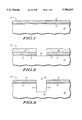
- FIGS. 1-11illustrate, in cross-section, process steps in accordance with one embodiment of the invention.
- FIGS. 1 through 11illustrate, in cross-section, process steps in accordance with one embodiment of the invention wherein a trench isolation structure is formed in an integrated circuit.
- a portion 10 of an integrated circuit structurecomprising a semiconductor substrate 12, a buffer layer 13, and an oxidation resistant layer 15.
- Semiconductor substrate 12is preferably a monocrystalline silicon substrate.
- semiconductor substrate 12can also be a silicon on insulator substrate, a silicon on sapphire substrate, or the like.
- Buffer layer 13is preferably a layer of thermally grown silicon dioxide having a thickness ranging from 10 to 25 nanometers.
- buffer layer 13can be chemical vapor deposited silicon dioxide.
- Oxidation resistant layer 15is preferably chemical vapor deposited silicon nitride having a thickness ranging from 50 to 200 nanometers.
- oxidation resistant layer 15can also be another material, such as silicon oxynitride.
- a photoresist mask 18which overlies a portion of oxidation resistant layer 15, is used to pattern oxidation resistant layer 15 and underlying buffer layer 13 so that a remaining portion 16 of oxidation resistant layer 15 is left overlying a remaining portion 14 of buffer layer 13, and a first portion 20 of semiconductor substrate 12 is exposed.
- Photoresist mask 18can be formed using standard photolithographic patterning processes, and oxidation resistant layer 15 and buffer layer 13 can be patterned using standard etching techniques.
- first portion 20 of semiconductor substrate 12is then anisotropically etched using standard etching techniques to form a trench 22 having a trench sidewall 24 and a trench bottom 26.
- photoresist mask 18is removed using standard photoresist stripping techniques.
- Trench 22preferably has a trench width ranging from about 200 to 600 nanometers and a trench depth ranging from about 200 to 1000 nanometers.
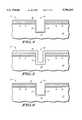
- a silicon layer 28is then formed which overlies remaining portion 16 of oxidation resistant layer 15 and lies within trench 22. Silicon layer 28 abuts trench sidewall 24 and trench bottom 26 and has a thickness that is insufficient to fill trench 22.
- silicon layer 28is a layer of polysilicon.
- silicon layer 28can also be a layer of amorphous silicon. Silicon layer 28 may have a thickness ranging from 5 to 60 nanometers and can be formed using standard deposition techniques.
- first dielectric layer 30is then completely oxidized in an ambient comprising oxygen to form a first dielectric layer 30 that lies within trench 22 and overlies remaining portion 16 of oxidation resistant layer 15.
- First dielectric layer 30has a thickness that is insufficient to fill trench 22.
- first dielectric layer 30is formed using a wet oxidation process. For example, if silicon layer 28 is a layer of polysilicon having a thickness of approximately 30 nanometers then first dielectric layer 30 can be formed by oxidizing the polysilicon layer in an ambient comprising oxygen and hydrogen for approximately 30 minutes at a temperature of approximately 950 degrees Celsius.
- first dielectric layer 30can also be formed using a dry oxidation process or a high pressure oxidation process.
- a portion of trench sidewall 24 and a portion of trench bottom 26is also oxidized when first dielectric layer 30 is formed.
- first dielectric layer 30is then isotropically etched to form an etched dielectric layer 32 that lies within trench 22 and overlies remaining portion 16 of oxidation resistant layer 15.
- first dielectric layer 30is formed with a surface topography that adversely effects the formation of a void free trench. Therefore, in order to overcome this adverse effect a portion of first dielectric layer 30 is removed to form etched dielectric layer 32 that has a surface topography, which is more conducive to the formation of a void free trench fill.
- first dielectric layer 30is etched using dilute hydrofluoric acid.
- first dielectric layer 30is formed with a 30 nanometer thick polysilicon layer, then it is preferably etched so that its thickness is reduced by approximately 500 angstroms.
- etched dielectric layer 32is then annealed in an oxidizing ambient.
- etched dielectric layer 32is annealed using a dry oxidation process.
- etched dielectric layer 32can be annealed in an ambient comprising dry oxygen for approximately 30 minutes at a temperature of approximately 900 degrees Celsius. It is believed that this anneal improves the electrical reliability of the final trench isolation structure by minimizing stress and fixed charge along trench sidewall 24 and trench bottom 26.
- second dielectric layer 34is then formed overlying etched dielectric layer 32 and substantially fills trench 22.
- second dielectric layer 34is chemically vapor deposited silicon dioxide, which is deposited using ozone and tetraethylorthosilicate (TEOS) as source gases.
- TEOStetraethylorthosilicate
- second dielectric layer 34can also be another dielectric material, such as germanium oxide, spin-on-glass, et cetera, or a combination of these dielectric materials.
- second dielectric layer 34can be formed using other techniques such as plasma enhanced chemical vapor deposition, electron cyclotron resonance deposition, or spin-on deposition.
- etched dielectric layer 32is formed prior to filling trench 22 with second dielectric layer 34, then keyhole or void formation within trench 22 is minimized.
- the oxidation and etch processeswhich form etched dielectric layer 32, create a profile that allows second dielectric layer 34 to be formed within trench 22 such that keyhole or void formation is minimized in trenches having a width of 600 nanometers or less.
- second dielectric layer 34can be annealed in either an inert or an oxidizing ambient in order to densify second dielectric layer 34.
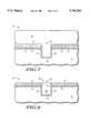
- trench plug 36comprises a remaining portion 33 of etched dielectric layer 32 and a remaining portion 35 of second dielectric layer 34 and substantially fills trench 22.
- chemical mechanical polishingis used to selectively remove a portion of second dielectric layer 34 and a portion of etched dielectric layer 32 to form trench plug 36.
- standard photo masking and etching techniquescan also be used to form trench plug 36.
- trench plug 36can also be formed using standard photo masking and etching techniques in combination with chemical mechanical polishing.
- device reliabilitycan be adversely effected by trench plugs that contain keyholes or voids.
- planarization process used to form the trench plugexposes a void that was created during the trench fill process, then a conductive filament or stringer will subsequently be formed within the void during gate electrode formation and adjacent gate electrodes can be shorted to one another via the conductive filament. Therefore, this invention allows device reliability to be improved because it allows void free trench plugs to be formed in trenches having widths of 600 nanometers or less.
- remaining portion 16 of oxidation resistant layer 15is then selectively removed to expose remaining portion 14 of buffer layer 13.
- remaining portion 16can be removed in phosphoric acid.
- remaining portion 16can also be removed using standard dry etching techniques.
- Remaining portion 14 of buffer layer 13is then annealed in an ambient comprising oxygen to form a sacrificial oxide layer 38 underlying remaining portion 14.
- sacrificial oxide layer 38is formed using a dry oxidation process and has a thickness ranging from 10 to 45 nanometers.
- a sacrificial oxide layer having a thickness of approximately 40 nanometerscan be formed by annealing remaining portion 14 in an ambient comprising dry oxygen at a temperature of approximately 1000 degrees Celsius for approximately 40 minutes. It should also be noted that a dry oxidation process allows a thin sacrificial oxide layer to be uniformly and controllably formed. The importance of a dry oxidation process will be more fully understood when sacrificial oxide layer 38 is subsequently removed.
- remaining portion 14 of buffer layer 13 and sacrificial oxide layer 38are then removed to expose a second portion 40 of semiconductor substrate 12.
- remaining portion 14 and sacrificial oxide layer 38are isotropically etched using dilute hydrofluoric acid.
- a portion of trench plug 36is also removed during the etch process. It should be noted that device reliability is also adversely affected when trench plugs are over etched. For example, over etching may expose a significant portion of the trench sidewall, thus creating a vertical surface upon which conductive filaments or stringers will form during subsequent gate electrode formation. Therefore, over etching can cause adjacent gate electrodes to be shorted to one another.
- the gate width of a parasitic transistor formed along the trench sidewallis also dependent on the amount the trench plug is over etched, and therefore, parasitic transistor leakage currents increase as the over etch of the trench plug increases.
- trench plug etchingis minimized with the present invention. This is because instead of being etched twice, first to remove remaining portion 14 and then again to remove a subsequently formed sacrificial oxide layer, trench plug 36 is only etched once. Moreover, because sacrificial oxide layer 38 has been controllably and uniformly formed the over etch needed to completely remove it is also minimized. Therefore, leakage currents and gate electrode shorts may be minimized with the present invention, and thus increased device reliability may be achieved.
- gate dielectric layer 42is then formed overlying second portion 40 of semiconductor substrate 12.
- gate dielectric layer 42is a layer of thermal silicon dioxide, which is formed by thermally oxidizing second portion 40.
- gate dielectric layer 42can be another dielectric material such as silicon oxynitride, which can be formed by thermally nitriding a layer of thermal silicon dioxide in an ambient containing ammonia (NH 3 ), nitrous oxide (N 2 O), or nitric oxide (NO).
- gate dielectric layer 42can also be formed by direct nitridation of second portion 40 in an ambient containing one of the previously mentioned gases.
- transistor gate electrode 44is then subsequently formed and patterned to form a transistor gate electrode 44 overlying trench plug 36 and gate dielectric layer 42.
- transistor gate electrode 44comprises polysilicon.
- transistor gate electrode 44can be a metal, a metal silicide or a composite comprising polysilicon and a metal or a metal silicide.
- a method for forming trench isolation structures with improved reliabilityis disclosed. More specifically, the present invention discloses that void or keyhole formation in trenches having submicron trench widths may be minimized by depositing a silicon layer within a trench, oxidizing the silicon layer to form a dielectric layer, and then etching the dielectric layer prior to filling the trench with a dielectric material.
- the present inventionalso teaches that over etching of subsequently formed trench plugs, which adversely effects device reliability, can be minimized by forming a sacrificial oxide layer with a dry oxidation process and then subsequently removing the sacrificial oxide layer at the same time that an overlying buffer layer is removed. Therefore, with the present invention integrated circuits with high device densities and high reliability may be manufactured.
Landscapes
- Engineering & Computer Science (AREA)
- Physics & Mathematics (AREA)
- Condensed Matter Physics & Semiconductors (AREA)
- General Physics & Mathematics (AREA)
- Manufacturing & Machinery (AREA)
- Computer Hardware Design (AREA)
- Microelectronics & Electronic Packaging (AREA)
- Power Engineering (AREA)
- Element Separation (AREA)
Abstract
Description
Claims (25)
Priority Applications (7)
| Application Number | Priority Date | Filing Date | Title |
|---|---|---|---|
| US08/416,243US5786263A (en) | 1995-04-04 | 1995-04-04 | Method for forming a trench isolation structure in an integrated circuit |
| TW085101342ATW348274B (en) | 1995-04-04 | 1996-02-03 | Method for forming a trench isolation structure in an integrated circuit |
| EP96104675AEP0736897B1 (en) | 1995-04-04 | 1996-03-25 | Method for forming a trench isolation structure in an integrated circuit |
| DE69623679TDE69623679T2 (en) | 1995-04-04 | 1996-03-25 | Process for producing a trench structure for isolation in an integrated circuit |
| JP10184596AJP4416843B2 (en) | 1995-04-04 | 1996-04-01 | Method for forming a trench isolation structure in an integrated circuit |
| KR1019960009824AKR100394517B1 (en) | 1995-04-04 | 1996-04-02 | A method for forming a trench isolation structure in an integrated circuit |
| JP2007001007AJP4168073B2 (en) | 1995-04-04 | 2007-01-09 | Method for forming a trench isolation structure in an integrated circuit |
Applications Claiming Priority (1)
| Application Number | Priority Date | Filing Date | Title |
|---|---|---|---|
| US08/416,243US5786263A (en) | 1995-04-04 | 1995-04-04 | Method for forming a trench isolation structure in an integrated circuit |
Publications (1)
| Publication Number | Publication Date |
|---|---|
| US5786263Atrue US5786263A (en) | 1998-07-28 |
Family
ID=23649176
Family Applications (1)
| Application Number | Title | Priority Date | Filing Date |
|---|---|---|---|
| US08/416,243Expired - LifetimeUS5786263A (en) | 1995-04-04 | 1995-04-04 | Method for forming a trench isolation structure in an integrated circuit |
Country Status (6)
| Country | Link |
|---|---|
| US (1) | US5786263A (en) |
| EP (1) | EP0736897B1 (en) |
| JP (2) | JP4416843B2 (en) |
| KR (1) | KR100394517B1 (en) |
| DE (1) | DE69623679T2 (en) |
| TW (1) | TW348274B (en) |
Cited By (81)
| Publication number | Priority date | Publication date | Assignee | Title |
|---|---|---|---|---|
| US5933748A (en)* | 1996-01-22 | 1999-08-03 | United Microelectronics Corp. | Shallow trench isolation process |
| US6010958A (en)* | 1997-05-20 | 2000-01-04 | United Microelectronics Corp. | Method for improving the planarization of dielectric layer in the fabrication of metallic interconnects |
| US6040233A (en)* | 1997-12-05 | 2000-03-21 | Stmicroelectronics, Inc. | Method of making a shallow trench isolation with thin nitride as gate dielectric |
| US6040211A (en)* | 1998-06-09 | 2000-03-21 | Siemens Aktiengesellschaft | Semiconductors having defect denuded zones |
| US6063691A (en)* | 1997-12-29 | 2000-05-16 | Lg Semicon Co., Ltd. | Shallow trench isolation (STI) fabrication method for semiconductor device |
| US6064104A (en)* | 1996-01-31 | 2000-05-16 | Advanced Micro Devices, Inc. | Trench isolation structures with oxidized silicon regions and method for making the same |
| US6071817A (en)* | 1998-03-23 | 2000-06-06 | Lsi Logic Corporation | Isolation method utilizing a high pressure oxidation |
| US6107143A (en)* | 1998-03-02 | 2000-08-22 | Samsung Electronics Co., Ltd. | Method for forming a trench isolation structure in an integrated circuit |
| US6118167A (en)* | 1997-11-13 | 2000-09-12 | National Semiconductor Corporation | Polysilicon coated nitride-lined shallow trench |
| US6140206A (en)* | 1999-06-14 | 2000-10-31 | Chartered Semiconductor Manufacturing Ltd. | Method to form shallow trench isolation structures |
| US6153478A (en)* | 1998-01-28 | 2000-11-28 | United Microelectronics Corp. | STI process for eliminating kink effect |
| US6180492B1 (en)* | 1999-01-25 | 2001-01-30 | United Microelectronics Corp. | Method of forming a liner for shallow trench isolation |
| US6200881B1 (en)* | 1999-07-23 | 2001-03-13 | Worldwide Semiconductor Manufacturing Corp. | Method of forming a shallow trench isolation |
| US6228741B1 (en)* | 1998-01-13 | 2001-05-08 | Texas Instruments Incorporated | Method for trench isolation of semiconductor devices |
| US6239041B1 (en) | 1997-03-05 | 2001-05-29 | Hitachi, Ltd. | Method for fabricating semiconductor integrated circuit device |
| US6251753B1 (en)* | 1999-11-23 | 2001-06-26 | Ching-Fa Yeh | Method of sidewall capping for degradation-free damascene trenches of low dielectric constant dielectric by selective liquid-phase deposition |
| US6265281B1 (en)* | 1997-08-18 | 2001-07-24 | Micron Technology, Inc. | Method for forming dielectric within a recess |
| US6274455B1 (en)* | 1997-12-29 | 2001-08-14 | Hyundai Electronics Industries Co., Ltd. | Method for isolating semiconductor device |
| US6281557B1 (en)* | 1997-07-30 | 2001-08-28 | Infineon Technologies Ag | Read-only memory cell array and method for fabricating it |
| US6284624B1 (en)* | 1999-01-06 | 2001-09-04 | Mitsubishi Denki Kabushiki Kaisha | Semiconductor device and method of manufacturing the same |
| US6291287B1 (en)* | 1995-08-07 | 2001-09-18 | Infineon Technologies Ag | Method for producing a memory cell |
| US6372604B1 (en)* | 1997-04-11 | 2002-04-16 | Mitsubishi Denki Kabushiki Kaisha | Method for forming a trench type element isolation structure and trench type element isolation structure |
| US6448150B1 (en)* | 1998-01-20 | 2002-09-10 | Nanya Technology Corporation | Method for forming shallow trench isolation in the integrated circuit |
| US20020197823A1 (en)* | 2001-05-18 | 2002-12-26 | Yoo Jae-Yoon | Isolation method for semiconductor device |
| US6524931B1 (en)* | 1999-07-20 | 2003-02-25 | Motorola, Inc. | Method for forming a trench isolation structure in an integrated circuit |
| KR100400301B1 (en)* | 1999-12-30 | 2003-10-01 | 주식회사 하이닉스반도체 | A method for forming a field oxide of semiconductor device |
| US20040082181A1 (en)* | 1999-08-30 | 2004-04-29 | Doan Trung Tri | Methods of forming trench isolation regions |
| US20040087107A1 (en)* | 2002-10-31 | 2004-05-06 | Sharp Kabushiki Kaisha | Method of semiconductor device fabrication |
| US6737359B1 (en)* | 1999-12-13 | 2004-05-18 | Taiwan Semiconductor Manufacturing Company | Method of forming a shallow trench isolation using a sion anti-reflective coating which eliminates water spot defects |
| US20040211674A1 (en)* | 2003-04-28 | 2004-10-28 | Taiwan Semiconductor Manufacturing Co., Ltd. | Gas distribution plate with anodized aluminum coating |
| US20050009368A1 (en)* | 2003-07-07 | 2005-01-13 | Vaartstra Brian A. | Methods of forming a phosphorus doped silicon dioxide comprising layer, and methods of forming trench isolation in the fabrication of integrated circuitry |
| US20050054213A1 (en)* | 2003-09-05 | 2005-03-10 | Derderian Garo J. | Methods of depositing a silicon dioxide comprising layer in the fabrication of integrated circuitry, and methods of forming trench isolation in the fabrication of integrated circuitry |
| US20050208778A1 (en)* | 2004-03-22 | 2005-09-22 | Weimin Li | Methods of depositing silicon dioxide comprising layers in the fabrication of integrated circuitry, methods of forming trench isolation, and methods of forming arrays of memory cells |
| US20060046425A1 (en)* | 2004-08-31 | 2006-03-02 | Sandhu Gurtej S | Methods of forming trench isolation in the fabrication of integrated circuitry, methods of fabricating memory circuitry, integrated circuitry and memory integrated circuitry |
| US20060183294A1 (en)* | 2005-02-17 | 2006-08-17 | Micron Technology, Inc. | Methods of forming integrated circuitry |
| US20060197225A1 (en)* | 2005-03-07 | 2006-09-07 | Qi Pan | Electrically conductive line, method of forming an electrically conductive line, and method of reducing titanium silicide agglomeration in fabrication of titanium silicide over polysilicon transistor gate lines |
| US20060223279A1 (en)* | 2005-04-01 | 2006-10-05 | Micron Technology, Inc. | Methods of forming trench isolation in the fabrication of integrated circuitry and methods of fabricating integrated circuitry |
| US20070054432A1 (en)* | 2005-08-22 | 2007-03-08 | Qimonda Ag | Method for producing a structure with a low aspect ratio |
| US20070174859A1 (en)* | 1998-05-23 | 2007-07-26 | Samsung Electronics Co., Ltd | Cartridge for an information recording medium |
| US20070281448A1 (en)* | 2006-05-30 | 2007-12-06 | Applied Materials, Inc. | Novel deposition-plasma cure cycle process to enhance film quality of silicon dioxide |
| US20070277734A1 (en)* | 2006-05-30 | 2007-12-06 | Applied Materials, Inc. | Process chamber for dielectric gapfill |
| US20070281496A1 (en)* | 2006-05-30 | 2007-12-06 | Applied Materials, Inc. | Chemical vapor deposition of high quality flow-like silicon dioxide using a silicon containing precursor and atomic oxygen |
| US20080026597A1 (en)* | 2006-05-30 | 2008-01-31 | Applied Materials, Inc. | Method for depositing and curing low-k films for gapfill and conformal film applications |
| US20090017616A1 (en)* | 2007-07-10 | 2009-01-15 | Stephan Grunow | Method for forming conductive structures |
| CN100461342C (en)* | 2005-04-18 | 2009-02-11 | 力晶半导体股份有限公司 | Method for forming groove type gate dielectric layer |
| US20090061647A1 (en)* | 2007-08-27 | 2009-03-05 | Applied Materials, Inc. | Curing methods for silicon dioxide thin films deposited from alkoxysilane precursor with harp ii process |
| US20090104790A1 (en)* | 2007-10-22 | 2009-04-23 | Applied Materials, Inc. | Methods for Forming a Dielectric Layer Within Trenches |
| US20090104755A1 (en)* | 2007-10-22 | 2009-04-23 | Applied Materials, Inc. | High quality silicon oxide films by remote plasma cvd from disilane precursors |
| US20110034035A1 (en)* | 2009-08-06 | 2011-02-10 | Applied Materials, Inc. | Stress management for tensile films |
| US20110045676A1 (en)* | 2009-08-18 | 2011-02-24 | Applied Materials, Inc. | Remote plasma source seasoning |
| US20110092061A1 (en)* | 2009-10-20 | 2011-04-21 | Yunjun Ho | Methods of Forming Silicon Oxides and Methods of Forming Interlevel Dielectrics |
| US7943531B2 (en) | 2007-10-22 | 2011-05-17 | Applied Materials, Inc. | Methods for forming a silicon oxide layer over a substrate |
| US7994019B1 (en) | 2010-04-01 | 2011-08-09 | Applied Materials, Inc. | Silicon-ozone CVD with reduced pattern loading using incubation period deposition |
| US8232176B2 (en)* | 2006-06-22 | 2012-07-31 | Applied Materials, Inc. | Dielectric deposition and etch back processes for bottom up gapfill |
| US8236708B2 (en) | 2010-03-09 | 2012-08-07 | Applied Materials, Inc. | Reduced pattern loading using bis(diethylamino)silane (C8H22N2Si) as silicon precursor |
| US8304351B2 (en) | 2010-01-07 | 2012-11-06 | Applied Materials, Inc. | In-situ ozone cure for radical-component CVD |
| US8318584B2 (en) | 2010-07-30 | 2012-11-27 | Applied Materials, Inc. | Oxide-rich liner layer for flowable CVD gapfill |
| US8329262B2 (en) | 2010-01-05 | 2012-12-11 | Applied Materials, Inc. | Dielectric film formation using inert gas excitation |
| US8357435B2 (en) | 2008-05-09 | 2013-01-22 | Applied Materials, Inc. | Flowable dielectric equipment and processes |
| US8445078B2 (en) | 2011-04-20 | 2013-05-21 | Applied Materials, Inc. | Low temperature silicon oxide conversion |
| US8450191B2 (en) | 2011-01-24 | 2013-05-28 | Applied Materials, Inc. | Polysilicon films by HDP-CVD |
| US8449942B2 (en) | 2009-11-12 | 2013-05-28 | Applied Materials, Inc. | Methods of curing non-carbon flowable CVD films |
| US8466073B2 (en) | 2011-06-03 | 2013-06-18 | Applied Materials, Inc. | Capping layer for reduced outgassing |
| US8476142B2 (en) | 2010-04-12 | 2013-07-02 | Applied Materials, Inc. | Preferential dielectric gapfill |
| US8524004B2 (en) | 2010-06-16 | 2013-09-03 | Applied Materials, Inc. | Loadlock batch ozone cure |
| US8551891B2 (en) | 2011-10-04 | 2013-10-08 | Applied Materials, Inc. | Remote plasma burn-in |
| US8563445B2 (en) | 2010-03-05 | 2013-10-22 | Applied Materials, Inc. | Conformal layers by radical-component CVD |
| US8617989B2 (en) | 2011-09-26 | 2013-12-31 | Applied Materials, Inc. | Liner property improvement |
| US8629067B2 (en) | 2009-12-30 | 2014-01-14 | Applied Materials, Inc. | Dielectric film growth with radicals produced using flexible nitrogen/hydrogen ratio |
| US8647992B2 (en) | 2010-01-06 | 2014-02-11 | Applied Materials, Inc. | Flowable dielectric using oxide liner |
| US8664127B2 (en) | 2010-10-15 | 2014-03-04 | Applied Materials, Inc. | Two silicon-containing precursors for gapfill enhancing dielectric liner |
| US8716154B2 (en) | 2011-03-04 | 2014-05-06 | Applied Materials, Inc. | Reduced pattern loading using silicon oxide multi-layers |
| US8741788B2 (en) | 2009-08-06 | 2014-06-03 | Applied Materials, Inc. | Formation of silicon oxide using non-carbon flowable CVD processes |
| US8889566B2 (en) | 2012-09-11 | 2014-11-18 | Applied Materials, Inc. | Low cost flowable dielectric films |
| US8980382B2 (en) | 2009-12-02 | 2015-03-17 | Applied Materials, Inc. | Oxygen-doping for non-carbon radical-component CVD films |
| US9018108B2 (en) | 2013-01-25 | 2015-04-28 | Applied Materials, Inc. | Low shrinkage dielectric films |
| US9285168B2 (en) | 2010-10-05 | 2016-03-15 | Applied Materials, Inc. | Module for ozone cure and post-cure moisture treatment |
| US9404178B2 (en) | 2011-07-15 | 2016-08-02 | Applied Materials, Inc. | Surface treatment and deposition for reduced outgassing |
| US9412581B2 (en) | 2014-07-16 | 2016-08-09 | Applied Materials, Inc. | Low-K dielectric gapfill by flowable deposition |
| US10283321B2 (en) | 2011-01-18 | 2019-05-07 | Applied Materials, Inc. | Semiconductor processing system and methods using capacitively coupled plasma |
| US12009228B2 (en) | 2015-02-03 | 2024-06-11 | Applied Materials, Inc. | Low temperature chuck for plasma processing systems |
Families Citing this family (10)
| Publication number | Priority date | Publication date | Assignee | Title |
|---|---|---|---|---|
| JP2891205B2 (en)* | 1996-10-21 | 1999-05-17 | 日本電気株式会社 | Manufacturing method of semiconductor integrated circuit |
| JPH118295A (en) | 1997-06-16 | 1999-01-12 | Nec Corp | Semiconductor device and its manufacture |
| FR2797603B1 (en)* | 1997-09-01 | 2004-01-16 | United Microelectronics Corp | CHEMICAL-MECHANICAL POLISHING MACHINE AND METHOD AND RETAINING SLEEVE USED IN THIS MACHINE |
| WO1999044223A2 (en)* | 1998-02-27 | 1999-09-02 | Lsi Logic Corporation | Process of shallow trench isolating active devices to avoid sub-threshold kinks arising from corner effects without additional processing |
| KR100283469B1 (en)* | 1998-06-08 | 2001-04-02 | 윤종용 | Semiconductor device manufacturing method |
| DE10110974C2 (en)* | 2001-03-07 | 2003-07-24 | Infineon Technologies Ag | Method for widening an active semiconductor region on a semiconductor substrate |
| US7422961B2 (en)* | 2003-03-14 | 2008-09-09 | Advanced Micro Devices, Inc. | Method of forming isolation regions for integrated circuits |
| US7754550B2 (en)* | 2003-07-10 | 2010-07-13 | International Rectifier Corporation | Process for forming thick oxides on Si or SiC for semiconductor devices |
| FR2876220B1 (en)* | 2004-10-06 | 2007-09-28 | Commissariat Energie Atomique | METHOD FOR PRODUCING MIXED STACKED STRUCTURES, VARIOUS INSULATING AREAS AND / OR LOCALIZED VERTICAL ELECTRICAL CONDUCTION ZONES. |
| FR2897982B1 (en) | 2006-02-27 | 2008-07-11 | Tracit Technologies Sa | METHOD FOR MANUFACTURING PARTIALLY-LIKE STRUCTURES, COMPRISING AREAS CONNECTING A SURFACE LAYER AND A SUBSTRATE |
Citations (8)
| Publication number | Priority date | Publication date | Assignee | Title |
|---|---|---|---|---|
| US4523369A (en)* | 1982-03-31 | 1985-06-18 | Tokyo Shibaura Denki Kabushiki Kaisha | Method for manufacturing a semiconductor device |
| US4666556A (en)* | 1986-05-12 | 1987-05-19 | International Business Machines Corporation | Trench sidewall isolation by polysilicon oxidation |
| US4714520A (en)* | 1985-07-25 | 1987-12-22 | Advanced Micro Devices, Inc. | Method for filling a trench in an integrated circuit structure without producing voids |
| US4927780A (en)* | 1989-10-02 | 1990-05-22 | Motorola, Inc. | Encapsulation method for localized oxidation of silicon |
| US5112772A (en)* | 1991-09-27 | 1992-05-12 | Motorola, Inc. | Method of fabricating a trench structure |
| US5175123A (en)* | 1990-11-13 | 1992-12-29 | Motorola, Inc. | High-pressure polysilicon encapsulated localized oxidation of silicon |
| US5246537A (en)* | 1992-04-30 | 1993-09-21 | Motorola, Inc. | Method of forming recessed oxide isolation |
| US5387540A (en)* | 1993-09-30 | 1995-02-07 | Motorola Inc. | Method of forming trench isolation structure in an integrated circuit |
Family Cites Families (3)
| Publication number | Priority date | Publication date | Assignee | Title |
|---|---|---|---|---|
| JPS63314844A (en)* | 1987-06-18 | 1988-12-22 | Toshiba Corp | Manufacture of semiconductor device |
| US5316965A (en)* | 1993-07-29 | 1994-05-31 | Digital Equipment Corporation | Method of decreasing the field oxide etch rate in isolation technology |
| US5294562A (en)* | 1993-09-27 | 1994-03-15 | United Microelectronics Corporation | Trench isolation with global planarization using flood exposure |
- 1995
- 1995-04-04USUS08/416,243patent/US5786263A/ennot_activeExpired - Lifetime
- 1996
- 1996-02-03TWTW085101342Apatent/TW348274B/ennot_activeIP Right Cessation
- 1996-03-25DEDE69623679Tpatent/DE69623679T2/ennot_activeExpired - Lifetime
- 1996-03-25EPEP96104675Apatent/EP0736897B1/ennot_activeExpired - Lifetime
- 1996-04-01JPJP10184596Apatent/JP4416843B2/ennot_activeExpired - Fee Related
- 1996-04-02KRKR1019960009824Apatent/KR100394517B1/ennot_activeExpired - Fee Related
- 2007
- 2007-01-09JPJP2007001007Apatent/JP4168073B2/ennot_activeExpired - Fee Related
Patent Citations (8)
| Publication number | Priority date | Publication date | Assignee | Title |
|---|---|---|---|---|
| US4523369A (en)* | 1982-03-31 | 1985-06-18 | Tokyo Shibaura Denki Kabushiki Kaisha | Method for manufacturing a semiconductor device |
| US4714520A (en)* | 1985-07-25 | 1987-12-22 | Advanced Micro Devices, Inc. | Method for filling a trench in an integrated circuit structure without producing voids |
| US4666556A (en)* | 1986-05-12 | 1987-05-19 | International Business Machines Corporation | Trench sidewall isolation by polysilicon oxidation |
| US4927780A (en)* | 1989-10-02 | 1990-05-22 | Motorola, Inc. | Encapsulation method for localized oxidation of silicon |
| US5175123A (en)* | 1990-11-13 | 1992-12-29 | Motorola, Inc. | High-pressure polysilicon encapsulated localized oxidation of silicon |
| US5112772A (en)* | 1991-09-27 | 1992-05-12 | Motorola, Inc. | Method of fabricating a trench structure |
| US5246537A (en)* | 1992-04-30 | 1993-09-21 | Motorola, Inc. | Method of forming recessed oxide isolation |
| US5387540A (en)* | 1993-09-30 | 1995-02-07 | Motorola Inc. | Method of forming trench isolation structure in an integrated circuit |
Non-Patent Citations (8)
| Title |
|---|
| C.A. Goodwin et al., MOS Gate Oxide Defects Related to Treatment of Silicon Nitride Coated Wafers Prior to Local Oxidation , J.Electrochem. Soc.: Solid State Sci. & Tech., May 1982, pp. 1066 1070.* |
| C.A. Goodwin et al.,"MOS Gate Oxide Defects Related to Treatment of Silicon Nitride Coated Wafers Prior to Local Oxidation", J.Electrochem. Soc.: Solid-State Sci. & Tech., May 1982, pp. 1066-1070. |
| G. Fuse et al., "A Practical Trench Isolation Technology With A Novel Planarization Process", Semiconductor Research Center, Matsushita Elec. Ind. Co., 732-IEDM 1987 IEEE, pp. 732-735. |
| G. Fuse et al., A Practical Trench Isolation Technology With A Novel Planarization Process , Semiconductor Research Center, Matsushita Elec. Ind. Co., 732 IEDM 1987 IEEE, pp. 732 735.* |
| IBM Corp., 1979, "Method For Forming Shallow Junction Semiconductor Devices", pp. 4868-4870. |
| IBM Corp., 1979, Method For Forming Shallow Junction Semiconductor Devices , pp. 4868 4870.* |
| T.A.Shankoff et al., Bird s Beak Configuration & Elimination of Gate Oxide Thinning Produced during Selective Oxidation , J.Electrochem. Soc.:Solid State Science and Tech., Jan.1980, pp. 216 222.* |
| T.A.Shankoff et al.,"Bird's Beak Configuration & Elimination of Gate Oxide Thinning Produced during Selective Oxidation", J.Electrochem. Soc.:Solid-State Science and Tech., Jan.1980, pp. 216-222. |
Cited By (149)
| Publication number | Priority date | Publication date | Assignee | Title |
|---|---|---|---|---|
| US6291287B1 (en)* | 1995-08-07 | 2001-09-18 | Infineon Technologies Ag | Method for producing a memory cell |
| USRE40275E1 (en)* | 1995-08-07 | 2008-04-29 | Infineon Technologies Ag | Method for producing a memory cell |
| US5933748A (en)* | 1996-01-22 | 1999-08-03 | United Microelectronics Corp. | Shallow trench isolation process |
| US6064104A (en)* | 1996-01-31 | 2000-05-16 | Advanced Micro Devices, Inc. | Trench isolation structures with oxidized silicon regions and method for making the same |
| US6962880B2 (en) | 1997-03-05 | 2005-11-08 | Renesas Technology Corp. | Method for fabricating semiconductor integrated circuit device |
| US20030219995A1 (en)* | 1997-03-05 | 2003-11-27 | Yoshikazu Tanabe | Method for fabricating semiconductor integrated circuit device |
| US20040157467A1 (en)* | 1997-03-05 | 2004-08-12 | Yoshikazu Tanabe | Method for fabricating semiconductor intergrated circuit device |
| US20040157468A1 (en)* | 1997-03-05 | 2004-08-12 | Yoshikazu Tanabe | Method for fabricating semiconductor integrated circuit device |
| US6855642B2 (en) | 1997-03-05 | 2005-02-15 | Renesas Technology Corp. | Method for fabricating semiconductor integrated circuit device |
| US7799690B2 (en) | 1997-03-05 | 2010-09-21 | Renesas Electronics Corporation | Method for fabricating semiconductor integrated circuit device |
| US20050208731A1 (en)* | 1997-03-05 | 2005-09-22 | Yoshikazu Tanabe | Method for fabricating semiconductor integrated circuit device |
| US20080045027A1 (en)* | 1997-03-05 | 2008-02-21 | Yoshikazu Tanabe | Method for fabricating semiconductor intergrated circuit device |
| US7250376B2 (en) | 1997-03-05 | 2007-07-31 | Renesas Technology Corp. | Method for fabricating semiconductor integrated circuit device |
| US20050227501A1 (en)* | 1997-03-05 | 2005-10-13 | Yoshikazu Tanabe | Method for fabricating semiconductor integrated circuit device |
| US6239041B1 (en) | 1997-03-05 | 2001-05-29 | Hitachi, Ltd. | Method for fabricating semiconductor integrated circuit device |
| US6518201B1 (en) | 1997-03-05 | 2003-02-11 | Hitachi, Ltd. | Method for fabricating semiconductor integrated circuit device |
| US6962881B2 (en) | 1997-03-05 | 2005-11-08 | Renesas Technology Corp. | Method for fabricating semiconductor integrated circuit device |
| US6596650B2 (en) | 1997-03-05 | 2003-07-22 | Hitachi, Ltd. | Method for fabricating semiconductor integrated circuit device |
| US6569780B2 (en) | 1997-03-05 | 2003-05-27 | Hitachi, Ltd. | Method for fabricating semiconductor integrated circuit device |
| US7053007B2 (en) | 1997-03-05 | 2006-05-30 | Renesas Technology Corp. | Method for fabricating semiconductor integrated circuit device |
| US6528431B2 (en) | 1997-03-05 | 2003-03-04 | Hitachi, Ltd. | Method for fabricating semiconductor integrated circuit drive using an oxygen and hydrogen catalyst |
| US20040161945A1 (en)* | 1997-03-05 | 2004-08-19 | Yoshikazu Tanabe | Method for fabricating semiconductor integrated circuit device |
| US6417114B2 (en) | 1997-03-05 | 2002-07-09 | Hitachi, Ltd. | Method for fabricating semiconductor integrated circuit device |
| US6518202B2 (en) | 1997-03-05 | 2003-02-11 | Hitachi, Ltd. | Method for fabricating semiconductor integrated circuit device |
| US7008880B2 (en) | 1997-03-05 | 2006-03-07 | Renesas Technology Corp. | Method for fabricating semiconductor integrated circuit device |
| US6372604B1 (en)* | 1997-04-11 | 2002-04-16 | Mitsubishi Denki Kabushiki Kaisha | Method for forming a trench type element isolation structure and trench type element isolation structure |
| US6010958A (en)* | 1997-05-20 | 2000-01-04 | United Microelectronics Corp. | Method for improving the planarization of dielectric layer in the fabrication of metallic interconnects |
| US6281557B1 (en)* | 1997-07-30 | 2001-08-28 | Infineon Technologies Ag | Read-only memory cell array and method for fabricating it |
| US6265281B1 (en)* | 1997-08-18 | 2001-07-24 | Micron Technology, Inc. | Method for forming dielectric within a recess |
| US6118167A (en)* | 1997-11-13 | 2000-09-12 | National Semiconductor Corporation | Polysilicon coated nitride-lined shallow trench |
| US6040233A (en)* | 1997-12-05 | 2000-03-21 | Stmicroelectronics, Inc. | Method of making a shallow trench isolation with thin nitride as gate dielectric |
| US6063691A (en)* | 1997-12-29 | 2000-05-16 | Lg Semicon Co., Ltd. | Shallow trench isolation (STI) fabrication method for semiconductor device |
| US6274455B1 (en)* | 1997-12-29 | 2001-08-14 | Hyundai Electronics Industries Co., Ltd. | Method for isolating semiconductor device |
| US6228741B1 (en)* | 1998-01-13 | 2001-05-08 | Texas Instruments Incorporated | Method for trench isolation of semiconductor devices |
| US6448150B1 (en)* | 1998-01-20 | 2002-09-10 | Nanya Technology Corporation | Method for forming shallow trench isolation in the integrated circuit |
| US6153478A (en)* | 1998-01-28 | 2000-11-28 | United Microelectronics Corp. | STI process for eliminating kink effect |
| US6107143A (en)* | 1998-03-02 | 2000-08-22 | Samsung Electronics Co., Ltd. | Method for forming a trench isolation structure in an integrated circuit |
| US6071817A (en)* | 1998-03-23 | 2000-06-06 | Lsi Logic Corporation | Isolation method utilizing a high pressure oxidation |
| US20070174859A1 (en)* | 1998-05-23 | 2007-07-26 | Samsung Electronics Co., Ltd | Cartridge for an information recording medium |
| US6040211A (en)* | 1998-06-09 | 2000-03-21 | Siemens Aktiengesellschaft | Semiconductors having defect denuded zones |
| US6284624B1 (en)* | 1999-01-06 | 2001-09-04 | Mitsubishi Denki Kabushiki Kaisha | Semiconductor device and method of manufacturing the same |
| US6180492B1 (en)* | 1999-01-25 | 2001-01-30 | United Microelectronics Corp. | Method of forming a liner for shallow trench isolation |
| US6140206A (en)* | 1999-06-14 | 2000-10-31 | Chartered Semiconductor Manufacturing Ltd. | Method to form shallow trench isolation structures |
| US6524931B1 (en)* | 1999-07-20 | 2003-02-25 | Motorola, Inc. | Method for forming a trench isolation structure in an integrated circuit |
| US6200881B1 (en)* | 1999-07-23 | 2001-03-13 | Worldwide Semiconductor Manufacturing Corp. | Method of forming a shallow trench isolation |
| US7012010B2 (en) | 1999-08-30 | 2006-03-14 | Micron Technology, Inc. | Methods of forming trench isolation regions |
| US20040082181A1 (en)* | 1999-08-30 | 2004-04-29 | Doan Trung Tri | Methods of forming trench isolation regions |
| US20050239265A1 (en)* | 1999-08-30 | 2005-10-27 | Doan Trung T | Method of forming trench isolation regions |
| US20050239266A1 (en)* | 1999-08-30 | 2005-10-27 | Doan Trung T | Method of forming trench isolation regions |
| US6251753B1 (en)* | 1999-11-23 | 2001-06-26 | Ching-Fa Yeh | Method of sidewall capping for degradation-free damascene trenches of low dielectric constant dielectric by selective liquid-phase deposition |
| US6737359B1 (en)* | 1999-12-13 | 2004-05-18 | Taiwan Semiconductor Manufacturing Company | Method of forming a shallow trench isolation using a sion anti-reflective coating which eliminates water spot defects |
| KR100400301B1 (en)* | 1999-12-30 | 2003-10-01 | 주식회사 하이닉스반도체 | A method for forming a field oxide of semiconductor device |
| DE10222083B4 (en)* | 2001-05-18 | 2010-09-23 | Samsung Electronics Co., Ltd., Suwon | Isolation method for a semiconductor device |
| US20020197823A1 (en)* | 2001-05-18 | 2002-12-26 | Yoo Jae-Yoon | Isolation method for semiconductor device |
| US20040087107A1 (en)* | 2002-10-31 | 2004-05-06 | Sharp Kabushiki Kaisha | Method of semiconductor device fabrication |
| US6927138B2 (en)* | 2002-10-31 | 2005-08-09 | Sharp Kabushiki Kaisha | Method of semiconductor device fabrication |
| US20040211674A1 (en)* | 2003-04-28 | 2004-10-28 | Taiwan Semiconductor Manufacturing Co., Ltd. | Gas distribution plate with anodized aluminum coating |
| US7790632B2 (en) | 2003-07-07 | 2010-09-07 | Micron Technology, Inc. | Methods of forming a phosphorus doped silicon dioxide-comprising layer |
| US7125815B2 (en) | 2003-07-07 | 2006-10-24 | Micron Technology, Inc. | Methods of forming a phosphorous doped silicon dioxide comprising layer |
| US7294556B2 (en) | 2003-07-07 | 2007-11-13 | Micron Technology, Inc. | Method of forming trench isolation in the fabrication of integrated circuitry |
| US20050124171A1 (en)* | 2003-07-07 | 2005-06-09 | Vaartstra Brian A. | Method of forming trench isolation in the fabrication of integrated circuitry |
| US20050009368A1 (en)* | 2003-07-07 | 2005-01-13 | Vaartstra Brian A. | Methods of forming a phosphorus doped silicon dioxide comprising layer, and methods of forming trench isolation in the fabrication of integrated circuitry |
| US20070161260A1 (en)* | 2003-07-07 | 2007-07-12 | Vaartstra Brian A | Methods of forming a phosphorus doped silicon dioxide-comprising layer |
| US7250378B2 (en) | 2003-09-05 | 2007-07-31 | Micron Technology, Inc. | Method of depositing a silicon dioxide-comprising layer in the fabrication of integrated circuitry |
| US7361614B2 (en) | 2003-09-05 | 2008-04-22 | Micron Technology, Inc. | Method of depositing a silicon dioxide comprising layer in the fabrication of integrated circuitry |
| US7250380B2 (en) | 2003-09-05 | 2007-07-31 | Micron Technology, Inc. | Method of depositing a silicon dioxide-comprising layer in the fabrication of integrated circuitry |
| US20060189158A1 (en)* | 2003-09-05 | 2006-08-24 | Derderian Garo J | Method of depositing a silicon dioxide-comprising layer in the fabrication of integrated circuitry |
| US7157385B2 (en) | 2003-09-05 | 2007-01-02 | Micron Technology, Inc. | Method of depositing a silicon dioxide-comprising layer in the fabrication of integrated circuitry |
| US7429541B2 (en) | 2003-09-05 | 2008-09-30 | Micron Technology, Inc. | Method of forming trench isolation in the fabrication of integrated circuitry |
| US20050054213A1 (en)* | 2003-09-05 | 2005-03-10 | Derderian Garo J. | Methods of depositing a silicon dioxide comprising layer in the fabrication of integrated circuitry, and methods of forming trench isolation in the fabrication of integrated circuitry |
| US20060183347A1 (en)* | 2003-09-05 | 2006-08-17 | Derderian Garo J | Method of depositing a silicon dioxide-comprising layer in the fabrication of integrated circuitry |
| US20060189159A1 (en)* | 2003-09-05 | 2006-08-24 | Derderian Garo J | Methods of depositing a silicon dioxide comprising layer in the fabrication of integrated circuitry, and methods of forming trench isolation in the fabrication of integrated circuitry |
| US20060008972A1 (en)* | 2003-09-05 | 2006-01-12 | Derderian Garo J | Method of forming trench isolation in the fabrication of integrated circuitry |
| US20050208778A1 (en)* | 2004-03-22 | 2005-09-22 | Weimin Li | Methods of depositing silicon dioxide comprising layers in the fabrication of integrated circuitry, methods of forming trench isolation, and methods of forming arrays of memory cells |
| US7053010B2 (en) | 2004-03-22 | 2006-05-30 | Micron Technology, Inc. | Methods of depositing silicon dioxide comprising layers in the fabrication of integrated circuitry, methods of forming trench isolation, and methods of forming arrays of memory cells |
| US20060160375A1 (en)* | 2004-03-22 | 2006-07-20 | Weimin Li | Method of depositing a silicon dioxide-comprising layer in the fabrication of integrated circuitry, methods of forming trench isolation in the fabrication of integrated circuitry, Method of depositing silicon dioxide-comprising layers in the fabrication of integrated circuitry, and methods of forming bit line over capacitor arrays of memory cells |
| US7470635B2 (en) | 2004-03-22 | 2008-12-30 | Micron Technology, Inc. | Method of depositing a silicon dioxide-comprising layer in the fabrication of integrated circuitry, methods of forming trench isolation in the fabrication of integrated circuitry, methods of depositing silicon dioxide-comprising layers in the fabrication of integrated circuitry, and methods of forming bit line over capacitor arrays of memory cells |
| US7364981B2 (en) | 2004-08-31 | 2008-04-29 | Micron Technology, Inc. | Methods of forming trench isolation in the fabrication of integrated circuitry, methods of fabricating memory circuitry, integrated circuitry and memory integrated circuitry |
| US20070023856A1 (en)* | 2004-08-31 | 2007-02-01 | Sandhu Gurtej S | Methods of forming trench isolation in the fabrication of integrated circuitry, methods of fabricating memory circuitry, integrated circuitry and memory integrated circuitry |
| US20070020881A1 (en)* | 2004-08-31 | 2007-01-25 | Sandhu Gurtej S | Methods of forming trench isolation in the fabrication of integrated circuitry, methods of fabricating memory circuitry, integrated circuitry and memory integrated circuitry |
| US20060046426A1 (en)* | 2004-08-31 | 2006-03-02 | Micron Technology, Inc. | Methods of forming trench isolation in the fabrication of integrated circuitry, methods of fabricating memory circuitry, integrated circuitry and memory integrated circuitry |
| US20060046425A1 (en)* | 2004-08-31 | 2006-03-02 | Sandhu Gurtej S | Methods of forming trench isolation in the fabrication of integrated circuitry, methods of fabricating memory circuitry, integrated circuitry and memory integrated circuitry |
| US7235459B2 (en) | 2004-08-31 | 2007-06-26 | Micron Technology, Inc. | Methods of forming trench isolation in the fabrication of integrated circuitry, methods of fabricating memory circuitry, integrated circuitry and memory integrated circuitry |
| US7387940B2 (en) | 2004-08-31 | 2008-06-17 | Micron Technology, Inc. | Methods of forming trench isolation in the fabrication of integrated circuitry, methods of fabricating memory circuitry, integrated circuitry and memory integrated circuitry |
| US7368800B2 (en) | 2004-08-31 | 2008-05-06 | Micron Technology, Inc. | Methods of forming trench isolation in the fabrication of integrated circuitry, methods of fabricating memory circuitry, integrated circuitry and memory integrated circuitry |
| US7368366B2 (en) | 2004-08-31 | 2008-05-06 | Micron Technology, Inc. | Methods of forming trench isolation in the fabrication of integrated circuitry, methods of fabricating memory circuitry, integrated circuitry and memory integrated circuitry |
| US20060183294A1 (en)* | 2005-02-17 | 2006-08-17 | Micron Technology, Inc. | Methods of forming integrated circuitry |
| US7217634B2 (en) | 2005-02-17 | 2007-05-15 | Micron Technology, Inc. | Methods of forming integrated circuitry |
| US20060197225A1 (en)* | 2005-03-07 | 2006-09-07 | Qi Pan | Electrically conductive line, method of forming an electrically conductive line, and method of reducing titanium silicide agglomeration in fabrication of titanium silicide over polysilicon transistor gate lines |
| US20080284025A1 (en)* | 2005-03-07 | 2008-11-20 | Qi Pan | Electrically Conductive Line |
| US7510966B2 (en) | 2005-03-07 | 2009-03-31 | Micron Technology, Inc. | Electrically conductive line, method of forming an electrically conductive line, and method of reducing titanium silicide agglomeration in fabrication of titanium silicide over polysilicon transistor gate lines |
| US8349699B2 (en) | 2005-04-01 | 2013-01-08 | Micron Technology, Inc. | Methods of forming trench isolation in the fabrication of integrated circuitry and methods of fabricating integrated circuitry |
| US8012847B2 (en) | 2005-04-01 | 2011-09-06 | Micron Technology, Inc. | Methods of forming trench isolation in the fabrication of integrated circuitry and methods of fabricating integrated circuitry |
| US20060223279A1 (en)* | 2005-04-01 | 2006-10-05 | Micron Technology, Inc. | Methods of forming trench isolation in the fabrication of integrated circuitry and methods of fabricating integrated circuitry |
| CN100461342C (en)* | 2005-04-18 | 2009-02-11 | 力晶半导体股份有限公司 | Method for forming groove type gate dielectric layer |
| US20070054432A1 (en)* | 2005-08-22 | 2007-03-08 | Qimonda Ag | Method for producing a structure with a low aspect ratio |
| US7825038B2 (en) | 2006-05-30 | 2010-11-02 | Applied Materials, Inc. | Chemical vapor deposition of high quality flow-like silicon dioxide using a silicon containing precursor and atomic oxygen |
| US7902080B2 (en) | 2006-05-30 | 2011-03-08 | Applied Materials, Inc. | Deposition-plasma cure cycle process to enhance film quality of silicon dioxide |
| US20070281448A1 (en)* | 2006-05-30 | 2007-12-06 | Applied Materials, Inc. | Novel deposition-plasma cure cycle process to enhance film quality of silicon dioxide |
| US7790634B2 (en) | 2006-05-30 | 2010-09-07 | Applied Materials, Inc | Method for depositing and curing low-k films for gapfill and conformal film applications |
| US20080026597A1 (en)* | 2006-05-30 | 2008-01-31 | Applied Materials, Inc. | Method for depositing and curing low-k films for gapfill and conformal film applications |
| US20070281496A1 (en)* | 2006-05-30 | 2007-12-06 | Applied Materials, Inc. | Chemical vapor deposition of high quality flow-like silicon dioxide using a silicon containing precursor and atomic oxygen |
| US20070277734A1 (en)* | 2006-05-30 | 2007-12-06 | Applied Materials, Inc. | Process chamber for dielectric gapfill |
| US8232176B2 (en)* | 2006-06-22 | 2012-07-31 | Applied Materials, Inc. | Dielectric deposition and etch back processes for bottom up gapfill |
| US7833893B2 (en)* | 2007-07-10 | 2010-11-16 | International Business Machines Corporation | Method for forming conductive structures |
| US20090017616A1 (en)* | 2007-07-10 | 2009-01-15 | Stephan Grunow | Method for forming conductive structures |
| US7745352B2 (en) | 2007-08-27 | 2010-06-29 | Applied Materials, Inc. | Curing methods for silicon dioxide thin films deposited from alkoxysilane precursor with harp II process |
| US20090061647A1 (en)* | 2007-08-27 | 2009-03-05 | Applied Materials, Inc. | Curing methods for silicon dioxide thin films deposited from alkoxysilane precursor with harp ii process |
| US7803722B2 (en) | 2007-10-22 | 2010-09-28 | Applied Materials, Inc | Methods for forming a dielectric layer within trenches |
| US7867923B2 (en) | 2007-10-22 | 2011-01-11 | Applied Materials, Inc. | High quality silicon oxide films by remote plasma CVD from disilane precursors |
| US20090104790A1 (en)* | 2007-10-22 | 2009-04-23 | Applied Materials, Inc. | Methods for Forming a Dielectric Layer Within Trenches |
| US8242031B2 (en) | 2007-10-22 | 2012-08-14 | Applied Materials, Inc. | High quality silicon oxide films by remote plasma CVD from disilane precursors |
| US7943531B2 (en) | 2007-10-22 | 2011-05-17 | Applied Materials, Inc. | Methods for forming a silicon oxide layer over a substrate |
| US20090104755A1 (en)* | 2007-10-22 | 2009-04-23 | Applied Materials, Inc. | High quality silicon oxide films by remote plasma cvd from disilane precursors |
| US8357435B2 (en) | 2008-05-09 | 2013-01-22 | Applied Materials, Inc. | Flowable dielectric equipment and processes |
| US8741788B2 (en) | 2009-08-06 | 2014-06-03 | Applied Materials, Inc. | Formation of silicon oxide using non-carbon flowable CVD processes |
| US7935643B2 (en) | 2009-08-06 | 2011-05-03 | Applied Materials, Inc. | Stress management for tensile films |
| US20110034035A1 (en)* | 2009-08-06 | 2011-02-10 | Applied Materials, Inc. | Stress management for tensile films |
| US7989365B2 (en) | 2009-08-18 | 2011-08-02 | Applied Materials, Inc. | Remote plasma source seasoning |
| US20110045676A1 (en)* | 2009-08-18 | 2011-02-24 | Applied Materials, Inc. | Remote plasma source seasoning |
| US8105956B2 (en) | 2009-10-20 | 2012-01-31 | Micron Technology, Inc. | Methods of forming silicon oxides and methods of forming interlevel dielectrics |
| US20110092061A1 (en)* | 2009-10-20 | 2011-04-21 | Yunjun Ho | Methods of Forming Silicon Oxides and Methods of Forming Interlevel Dielectrics |
| US8450218B2 (en) | 2009-10-20 | 2013-05-28 | Micron Technology, Inc. | Methods of forming silicon oxides and methods of forming interlevel dielectrics |
| US8449942B2 (en) | 2009-11-12 | 2013-05-28 | Applied Materials, Inc. | Methods of curing non-carbon flowable CVD films |
| US8980382B2 (en) | 2009-12-02 | 2015-03-17 | Applied Materials, Inc. | Oxygen-doping for non-carbon radical-component CVD films |
| US8629067B2 (en) | 2009-12-30 | 2014-01-14 | Applied Materials, Inc. | Dielectric film growth with radicals produced using flexible nitrogen/hydrogen ratio |
| US8329262B2 (en) | 2010-01-05 | 2012-12-11 | Applied Materials, Inc. | Dielectric film formation using inert gas excitation |
| US8647992B2 (en) | 2010-01-06 | 2014-02-11 | Applied Materials, Inc. | Flowable dielectric using oxide liner |
| US8304351B2 (en) | 2010-01-07 | 2012-11-06 | Applied Materials, Inc. | In-situ ozone cure for radical-component CVD |
| US8563445B2 (en) | 2010-03-05 | 2013-10-22 | Applied Materials, Inc. | Conformal layers by radical-component CVD |
| US8236708B2 (en) | 2010-03-09 | 2012-08-07 | Applied Materials, Inc. | Reduced pattern loading using bis(diethylamino)silane (C8H22N2Si) as silicon precursor |
| US7994019B1 (en) | 2010-04-01 | 2011-08-09 | Applied Materials, Inc. | Silicon-ozone CVD with reduced pattern loading using incubation period deposition |
| US8476142B2 (en) | 2010-04-12 | 2013-07-02 | Applied Materials, Inc. | Preferential dielectric gapfill |
| US8524004B2 (en) | 2010-06-16 | 2013-09-03 | Applied Materials, Inc. | Loadlock batch ozone cure |
| US8318584B2 (en) | 2010-07-30 | 2012-11-27 | Applied Materials, Inc. | Oxide-rich liner layer for flowable CVD gapfill |
| US9285168B2 (en) | 2010-10-05 | 2016-03-15 | Applied Materials, Inc. | Module for ozone cure and post-cure moisture treatment |
| US8664127B2 (en) | 2010-10-15 | 2014-03-04 | Applied Materials, Inc. | Two silicon-containing precursors for gapfill enhancing dielectric liner |
| US10283321B2 (en) | 2011-01-18 | 2019-05-07 | Applied Materials, Inc. | Semiconductor processing system and methods using capacitively coupled plasma |
| US8450191B2 (en) | 2011-01-24 | 2013-05-28 | Applied Materials, Inc. | Polysilicon films by HDP-CVD |
| US8716154B2 (en) | 2011-03-04 | 2014-05-06 | Applied Materials, Inc. | Reduced pattern loading using silicon oxide multi-layers |
| US8445078B2 (en) | 2011-04-20 | 2013-05-21 | Applied Materials, Inc. | Low temperature silicon oxide conversion |
| US8466073B2 (en) | 2011-06-03 | 2013-06-18 | Applied Materials, Inc. | Capping layer for reduced outgassing |
| US9404178B2 (en) | 2011-07-15 | 2016-08-02 | Applied Materials, Inc. | Surface treatment and deposition for reduced outgassing |
| US8617989B2 (en) | 2011-09-26 | 2013-12-31 | Applied Materials, Inc. | Liner property improvement |
| US8551891B2 (en) | 2011-10-04 | 2013-10-08 | Applied Materials, Inc. | Remote plasma burn-in |
| US8889566B2 (en) | 2012-09-11 | 2014-11-18 | Applied Materials, Inc. | Low cost flowable dielectric films |
| US9018108B2 (en) | 2013-01-25 | 2015-04-28 | Applied Materials, Inc. | Low shrinkage dielectric films |
| US9412581B2 (en) | 2014-07-16 | 2016-08-09 | Applied Materials, Inc. | Low-K dielectric gapfill by flowable deposition |
| US12009228B2 (en) | 2015-02-03 | 2024-06-11 | Applied Materials, Inc. | Low temperature chuck for plasma processing systems |
Also Published As
| Publication number | Publication date |
|---|---|
| EP0736897A2 (en) | 1996-10-09 |
| JP4168073B2 (en) | 2008-10-22 |
| KR100394517B1 (en) | 2003-10-17 |
| DE69623679T2 (en) | 2003-05-22 |
| EP0736897A3 (en) | 1998-03-11 |
| DE69623679D1 (en) | 2002-10-24 |
| TW348274B (en) | 1998-12-21 |
| KR960036914A (en) | 1996-11-19 |
| JPH08279552A (en) | 1996-10-22 |
| JP2007096353A (en) | 2007-04-12 |
| JP4416843B2 (en) | 2010-02-17 |
| EP0736897B1 (en) | 2002-09-18 |
Similar Documents
| Publication | Publication Date | Title |
|---|---|---|
| US5786263A (en) | Method for forming a trench isolation structure in an integrated circuit | |
| US6524931B1 (en) | Method for forming a trench isolation structure in an integrated circuit | |
| EP0646956B1 (en) | Method of formation of a trench isolation structure in an integrated circuit | |
| US5604159A (en) | Method of making a contact structure | |
| US6627512B2 (en) | Method of manufacturing a semiconductor device | |
| US6165854A (en) | Method to form shallow trench isolation with an oxynitride buffer layer | |
| US5406111A (en) | Protection device for an intergrated circuit and method of formation | |
| US5882981A (en) | Mesa isolation Refill Process for Silicon on Insulator Technology Using Flowage Oxides as the Refill Material | |
| US5445107A (en) | Semiconductor device and method of formation | |
| JPH11145273A (en) | Method for manufacturing semiconductor device | |
| US20030209760A1 (en) | Semiconductor integrated circuit and method of fabricating the same | |
| JP2001196576A (en) | Semiconductor device and method of manufacturing the same | |
| US20020025654A1 (en) | Method for manufacturing a semiconductor device | |
| JPH0817813A (en) | Manufacture of semiconductor device | |
| US5998302A (en) | Method of manufacturing semiconductor device | |
| JP2002190515A (en) | Semiconductor device and method of manufacturing the same | |
| US6696743B1 (en) | Semiconductor transistor having gate electrode and/or gate wiring | |
| JP2000031489A (en) | Method for manufacturing semiconductor device | |
| JP2002100670A (en) | Semiconductor device and its manufacturing method | |
| JP3053009B2 (en) | Method for manufacturing semiconductor device | |
| JPH05226466A (en) | Manufacture of semiconductor device | |
| JPH09205137A (en) | Method for forming element isolation region | |
| JP3523244B1 (en) | Method for manufacturing semiconductor device | |
| JP2001244327A (en) | Method for manufacturing semiconductor device | |
| KR19990076326A (en) | Device isolation method of semiconductor device |
Legal Events
| Date | Code | Title | Description |
|---|---|---|---|
| AS | Assignment | Owner name:MOTOROLA, INC., ILLINOIS Free format text:ASSIGNMENT OF ASSIGNORS INTEREST;ASSIGNOR:PERERA, ASANGA H.;REEL/FRAME:007454/0534 Effective date:19950328 | |
| STCF | Information on status: patent grant | Free format text:PATENTED CASE | |
| FPAY | Fee payment | Year of fee payment:4 | |
| AS | Assignment | Owner name:FREESCALE SEMICONDUCTOR, INC., TEXAS Free format text:ASSIGNMENT OF ASSIGNORS INTEREST;ASSIGNOR:MOTOROLA, INC.;REEL/FRAME:015698/0657 Effective date:20040404 Owner name:FREESCALE SEMICONDUCTOR, INC.,TEXAS Free format text:ASSIGNMENT OF ASSIGNORS INTEREST;ASSIGNOR:MOTOROLA, INC.;REEL/FRAME:015698/0657 Effective date:20040404 | |
| FPAY | Fee payment | Year of fee payment:8 | |
| AS | Assignment | Owner name:CITIBANK, N.A. AS COLLATERAL AGENT, NEW YORK Free format text:SECURITY AGREEMENT;ASSIGNORS:FREESCALE SEMICONDUCTOR, INC.;FREESCALE ACQUISITION CORPORATION;FREESCALE ACQUISITION HOLDINGS CORP.;AND OTHERS;REEL/FRAME:018855/0129 Effective date:20061201 Owner name:CITIBANK, N.A. AS COLLATERAL AGENT,NEW YORK Free format text:SECURITY AGREEMENT;ASSIGNORS:FREESCALE SEMICONDUCTOR, INC.;FREESCALE ACQUISITION CORPORATION;FREESCALE ACQUISITION HOLDINGS CORP.;AND OTHERS;REEL/FRAME:018855/0129 Effective date:20061201 | |
| FPAY | Fee payment | Year of fee payment:12 | |
| AS | Assignment | Owner name:CITIBANK, N.A., AS COLLATERAL AGENT,NEW YORK Free format text:SECURITY AGREEMENT;ASSIGNOR:FREESCALE SEMICONDUCTOR, INC.;REEL/FRAME:024397/0001 Effective date:20100413 Owner name:CITIBANK, N.A., AS COLLATERAL AGENT, NEW YORK Free format text:SECURITY AGREEMENT;ASSIGNOR:FREESCALE SEMICONDUCTOR, INC.;REEL/FRAME:024397/0001 Effective date:20100413 | |
| AS | Assignment | Owner name:CITIBANK, N.A., AS NOTES COLLATERAL AGENT, NEW YORK Free format text:SECURITY AGREEMENT;ASSIGNOR:FREESCALE SEMICONDUCTOR, INC.;REEL/FRAME:030633/0424 Effective date:20130521 Owner name:CITIBANK, N.A., AS NOTES COLLATERAL AGENT, NEW YOR Free format text:SECURITY AGREEMENT;ASSIGNOR:FREESCALE SEMICONDUCTOR, INC.;REEL/FRAME:030633/0424 Effective date:20130521 | |
| AS | Assignment | Owner name:CITIBANK, N.A., AS NOTES COLLATERAL AGENT, NEW YORK Free format text:SECURITY AGREEMENT;ASSIGNOR:FREESCALE SEMICONDUCTOR, INC.;REEL/FRAME:031591/0266 Effective date:20131101 Owner name:CITIBANK, N.A., AS NOTES COLLATERAL AGENT, NEW YOR Free format text:SECURITY AGREEMENT;ASSIGNOR:FREESCALE SEMICONDUCTOR, INC.;REEL/FRAME:031591/0266 Effective date:20131101 | |
| AS | Assignment | Owner name:FREESCALE SEMICONDUCTOR, INC., TEXAS Free format text:PATENT RELEASE;ASSIGNOR:CITIBANK, N.A., AS COLLATERAL AGENT;REEL/FRAME:037356/0143 Effective date:20151207 Owner name:FREESCALE SEMICONDUCTOR, INC., TEXAS Free format text:PATENT RELEASE;ASSIGNOR:CITIBANK, N.A., AS COLLATERAL AGENT;REEL/FRAME:037356/0553 Effective date:20151207 Owner name:FREESCALE SEMICONDUCTOR, INC., TEXAS Free format text:PATENT RELEASE;ASSIGNOR:CITIBANK, N.A., AS COLLATERAL AGENT;REEL/FRAME:037354/0225 Effective date:20151207 | |
| AS | Assignment | Owner name:MORGAN STANLEY SENIOR FUNDING, INC., MARYLAND Free format text:ASSIGNMENT AND ASSUMPTION OF SECURITY INTEREST IN PATENTS;ASSIGNOR:CITIBANK, N.A.;REEL/FRAME:037486/0517 Effective date:20151207 | |
| AS | Assignment | Owner name:MORGAN STANLEY SENIOR FUNDING, INC., MARYLAND Free format text:ASSIGNMENT AND ASSUMPTION OF SECURITY INTEREST IN PATENTS;ASSIGNOR:CITIBANK, N.A.;REEL/FRAME:037518/0292 Effective date:20151207 | |
| AS | Assignment | Owner name:NXP, B.V., F/K/A FREESCALE SEMICONDUCTOR, INC., NETHERLANDS Free format text:RELEASE BY SECURED PARTY;ASSIGNOR:MORGAN STANLEY SENIOR FUNDING, INC.;REEL/FRAME:040925/0001 Effective date:20160912 Owner name:NXP, B.V., F/K/A FREESCALE SEMICONDUCTOR, INC., NE Free format text:RELEASE BY SECURED PARTY;ASSIGNOR:MORGAN STANLEY SENIOR FUNDING, INC.;REEL/FRAME:040925/0001 Effective date:20160912 | |
| AS | Assignment | Owner name:NXP B.V., NETHERLANDS Free format text:RELEASE BY SECURED PARTY;ASSIGNOR:MORGAN STANLEY SENIOR FUNDING, INC.;REEL/FRAME:040928/0001 Effective date:20160622 | |
| AS | Assignment | Owner name:MORGAN STANLEY SENIOR FUNDING, INC., MARYLAND Free format text:CORRECTIVE ASSIGNMENT TO CORRECT THE REMOVE PATENTS 8108266 AND 8062324 AND REPLACE THEM WITH 6108266 AND 8060324 PREVIOUSLY RECORDED ON REEL 037518 FRAME 0292. ASSIGNOR(S) HEREBY CONFIRMS THE ASSIGNMENT AND ASSUMPTION OF SECURITY INTEREST IN PATENTS;ASSIGNOR:CITIBANK, N.A.;REEL/FRAME:041703/0536 Effective date:20151207 | |
| AS | Assignment | Owner name:SHENZHEN XINGUODU TECHNOLOGY CO., LTD., CHINA Free format text:CORRECTIVE ASSIGNMENT TO CORRECT THE TO CORRECT THE APPLICATION NO. FROM 13,883,290 TO 13,833,290 PREVIOUSLY RECORDED ON REEL 041703 FRAME 0536. ASSIGNOR(S) HEREBY CONFIRMS THE THE ASSIGNMENT AND ASSUMPTION OF SECURITYINTEREST IN PATENTS.;ASSIGNOR:MORGAN STANLEY SENIOR FUNDING, INC.;REEL/FRAME:048734/0001 Effective date:20190217 | |
| AS | Assignment | Owner name:MORGAN STANLEY SENIOR FUNDING, INC., MARYLAND Free format text:CORRECTIVE ASSIGNMENT TO CORRECT THE REMOVE APPLICATION11759915 AND REPLACE IT WITH APPLICATION 11759935 PREVIOUSLY RECORDED ON REEL 037486 FRAME 0517. ASSIGNOR(S) HEREBY CONFIRMS THE ASSIGNMENT AND ASSUMPTION OF SECURITYINTEREST IN PATENTS;ASSIGNOR:CITIBANK, N.A.;REEL/FRAME:053547/0421 Effective date:20151207 | |
| AS | Assignment | Owner name:NXP B.V., NETHERLANDS Free format text:CORRECTIVE ASSIGNMENT TO CORRECT THE REMOVEAPPLICATION 11759915 AND REPLACE IT WITH APPLICATION11759935 PREVIOUSLY RECORDED ON REEL 040928 FRAME 0001. ASSIGNOR(S) HEREBY CONFIRMS THE RELEASE OF SECURITYINTEREST;ASSIGNOR:MORGAN STANLEY SENIOR FUNDING, INC.;REEL/FRAME:052915/0001 Effective date:20160622 | |
| AS | Assignment | Owner name:NXP, B.V. F/K/A FREESCALE SEMICONDUCTOR, INC., NETHERLANDS Free format text:CORRECTIVE ASSIGNMENT TO CORRECT THE REMOVEAPPLICATION 11759915 AND REPLACE IT WITH APPLICATION11759935 PREVIOUSLY RECORDED ON REEL 040925 FRAME 0001. ASSIGNOR(S) HEREBY CONFIRMS THE RELEASE OF SECURITYINTEREST;ASSIGNOR:MORGAN STANLEY SENIOR FUNDING, INC.;REEL/FRAME:052917/0001 Effective date:20160912 |