US5785411A - Track lighting system - Google Patents
Track lighting systemDownload PDFInfo
- Publication number
- US5785411A US5785411AUS08/738,775US73877596AUS5785411AUS 5785411 AUS5785411 AUS 5785411AUS 73877596 AUS73877596 AUS 73877596AUS 5785411 AUS5785411 AUS 5785411A
- Authority
- US
- United States
- Prior art keywords
- track
- connector
- members
- recited
- connectors
- Prior art date
- Legal status (The legal status is an assumption and is not a legal conclusion. Google has not performed a legal analysis and makes no representation as to the accuracy of the status listed.)
- Expired - Lifetime
Links
- 238000005286illuminationMethods0.000claimsdescription19
- 239000012777electrically insulating materialSubstances0.000claimsdescription2
- 230000013011matingEffects0.000claimsdescription2
- 238000010276constructionMethods0.000claims1
- 239000002184metalSubstances0.000abstractdescription4
- 239000004020conductorSubstances0.000description3
- 238000004519manufacturing processMethods0.000description2
- 238000012986modificationMethods0.000description2
- 230000004048modificationEffects0.000description2
- 230000006978adaptationEffects0.000description1
- 238000005452bendingMethods0.000description1
- 238000001125extrusionMethods0.000description1
- 238000010438heat treatmentMethods0.000description1
- 238000009434installationMethods0.000description1
- 230000008520organizationEffects0.000description1
- 238000013021overheatingMethods0.000description1
- 239000004033plasticSubstances0.000description1
- 238000009877renderingMethods0.000description1
- 239000012815thermoplastic materialSubstances0.000description1
Images
Classifications
- H—ELECTRICITY
- H01—ELECTRIC ELEMENTS
- H01R—ELECTRICALLY-CONDUCTIVE CONNECTIONS; STRUCTURAL ASSOCIATIONS OF A PLURALITY OF MUTUALLY-INSULATED ELECTRICAL CONNECTING ELEMENTS; COUPLING DEVICES; CURRENT COLLECTORS
- H01R33/00—Coupling devices specially adapted for supporting apparatus and having one part acting as a holder providing support and electrical connection via a counterpart which is structurally associated with the apparatus, e.g. lamp holders; Separate parts thereof
- H01R33/05—Two-pole devices
- F—MECHANICAL ENGINEERING; LIGHTING; HEATING; WEAPONS; BLASTING
- F21—LIGHTING
- F21S—NON-PORTABLE LIGHTING DEVICES; SYSTEMS THEREOF; VEHICLE LIGHTING DEVICES SPECIALLY ADAPTED FOR VEHICLE EXTERIORS
- F21S4/00—Lighting devices or systems using a string or strip of light sources
- F21S4/20—Lighting devices or systems using a string or strip of light sources with light sources held by or within elongate supports
- F—MECHANICAL ENGINEERING; LIGHTING; HEATING; WEAPONS; BLASTING
- F21—LIGHTING
- F21V—FUNCTIONAL FEATURES OR DETAILS OF LIGHTING DEVICES OR SYSTEMS THEREOF; STRUCTURAL COMBINATIONS OF LIGHTING DEVICES WITH OTHER ARTICLES, NOT OTHERWISE PROVIDED FOR
- F21V19/00—Fastening of light sources or lamp holders
- F21V19/0075—Fastening of light sources or lamp holders of tubular light sources, e.g. ring-shaped fluorescent light sources
- F21V19/008—Fastening of light sources or lamp holders of tubular light sources, e.g. ring-shaped fluorescent light sources of straight tubular light sources, e.g. straight fluorescent tubes, soffit lamps
- F21V19/0085—Fastening of light sources or lamp holders of tubular light sources, e.g. ring-shaped fluorescent light sources of straight tubular light sources, e.g. straight fluorescent tubes, soffit lamps at least one conductive element acting as a support means, e.g. resilient contact blades, piston-like contact
- F—MECHANICAL ENGINEERING; LIGHTING; HEATING; WEAPONS; BLASTING
- F21—LIGHTING
- F21V—FUNCTIONAL FEATURES OR DETAILS OF LIGHTING DEVICES OR SYSTEMS THEREOF; STRUCTURAL COMBINATIONS OF LIGHTING DEVICES WITH OTHER ARTICLES, NOT OTHERWISE PROVIDED FOR
- F21V21/00—Supporting, suspending, or attaching arrangements for lighting devices; Hand grips
- F21V21/34—Supporting elements displaceable along a guiding element
- F21V21/35—Supporting elements displaceable along a guiding element with direct electrical contact between the supporting element and electric conductors running along the guiding element
- H—ELECTRICITY
- H01—ELECTRIC ELEMENTS
- H01R—ELECTRICALLY-CONDUCTIVE CONNECTIONS; STRUCTURAL ASSOCIATIONS OF A PLURALITY OF MUTUALLY-INSULATED ELECTRICAL CONNECTING ELEMENTS; COUPLING DEVICES; CURRENT COLLECTORS
- H01R25/00—Coupling parts adapted for simultaneous co-operation with two or more identical counterparts, e.g. for distributing energy to two or more circuits
- H01R25/14—Rails or bus-bars constructed so that the counterparts can be connected thereto at any point along their length
- H01R25/142—Their counterparts
Definitions
- the inventionrelates generally to lighting systems and, more particularly, to a track lighting system whereby electrical and mechanical connections are achieved simultaneously to one or more lighting devices mounted to said system.
- an electrical distribution systemcan include a connection which is slidably adjustable along a length of track such that an illumination means can be positioned in multiple positions along the track, such as that of Cummings, U.S. Pat. No. 4,655,520.
- Cummingsteaches a C-shaped channel with a guide shoulder on each external outer edge to provide a mounting means upon which a lamp can slide along.
- a flexible insulated cableis disposed within the channel and electrical contact is made along the channel by a connector having barb means.
- the system of Leachdoes not permit simple placement of the connectors for quick positioning of the bulbs, but rather requires connectors be slid longitudinally along said track.
- the electrical wires which serve as the conduit for a distant power supplyare inconveniently disposed within the aforementioned channel, rendering them essentially inaccessible when the connectors and lighting device are in place. This can be especially problematic should contact between the wire and the connector become loose or disconnected resulting in a breach of the circuit.
- the present inventionaddresses these problems and difficulties with a novel system which employs electrically conducting connectors mounted to an electrically insulating track along a central slot or groove.
- the connectorcomprises a two opposed arcuate members which are adapted to releasably mount an end of a bulb or lamp.
- the arcuate membersare connected to a stem which mounts in the central groove of the track, and the connector also includes a leg member which assists in securing the connector to the track while providing the electrical contact to a cable disposed in the side of the track.
- the trackis preferably an elongate flat member which may be simply manufactured by extrusion of an electrically insulating material such as plastic.
- the trackcomprises a central groove located longitudinally along the length of the track which is adapted to mate with a connector's stem.
- the trackhas along each side a channel which houses an electrical cable such that when a voltage is applied across both cables there exists an electrical potential which may support a current.
- a tubular lampis placed between two connectors so that the arcuate members releasably grasp the conical ends of the lamp, and each connector is mounted to the track along the central groove.
- the connectorsare orientated such that each connector's leg member is inserted into one of the side channels such that contact is achieved between the electrical cable and the leg member, and an electrical current is created between the two cables through the lamp, thereby energizing the lamp.
- the present systemprovides several advantages over the prior art, such as distinctive orientation with regard to which electrical connection is being made, easy mounting and positioning of the connector anywhere along the track without deforming the connector, and visually accessible connection points from the cable to the connector. Moreover, the present system minimizes the possibility of a short circuit because the connectors are only connected to one of the two channels housing the electrical connections.
- the present inventionis simple to manufacture and the connectors are less likely to deform or lose their resiliency because they are not required to be deformed in order to be positioned on the track. This leads to longer life of the connectors and a more cost efficient system.
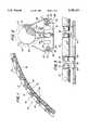
- FIG. 1is a perspective view of a preferred embodiment of the present invention
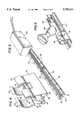
- FIG. 2is a profile view of the track and connector illustrating the central groove, the mating stem of the connector, and the channels housing the electrical connectors;
- FIG. 3is a side view of the track and connectors with a lamp disposed between the connectors;
- FIG. 4is a perspective view of the connector of the present invention.
- FIG. 5is an elevated view of the junction box and electrical connections
- FIG. 6is an elevated view of an alternate preferred embodiment.
- the present inventionis directed to a track lighting system 10 as illustrated generally in FIG. 1.
- a series of tubular lamps 12are connected in a linear end-to-end alignment along an elongated flexible track 16.
- the lamps 12have conical or cylindrical electrically conducting terminal ends 14 which, when connected to an electric circuit, energize the lamp 12.
- Each lamp 12is mounted to the elongate track 16 at its ends by insertable metal connectors 18.
- Each lamp 12utilizes two connectors 18 to mount the lamp mechanically, and each connector 18 also serves as the electrical connection for the lamp 12.
- Along the side 28 of the track 16are two channels 20, each of which house an electrically conductive cable or wire 22 such that the wire 22 is slightly exposed while secured in the channel 20.
- the connectors 18are capable of mounting along the track 16 at adjustable positions along a central groove 24, and the connectors 18 include a leg member 26 which electrically connects the wire 22 with the connector 18.
- the preceding descriptiondemonstrates a connector for the lamp which achieves both a mechanical and electrical connection of the lamp 12, and which will be described more fully below.
- the track 16is typically a thermoplastic material which is electrically insulating and can be readily extruded to its desired shape.
- the track 16comprises notches 30 along the side 28 in a spaced alignment to provide greater flexibility to the track 16 and allowing the track 16 to bend to follow lateral or radial bends (see FIG. 1). Such notches can be omitted in other embodiments.
- the track 16utilizes a pair of laterally protruding fingers 32 spaced apart to define a channel 20, 21 on each side of the track 16.
- the pairs of fingers 32extend longitudinally along the length of the track 16 to provide a housing for the electrically conducting wires 22, 23.
- FIG. 2illustrates a cross-sectional view of the track illustrating the channels 20, 21, the wires 22, 23, the track 16, and a connector 18.
- the track 16also comprises a groove 24 extending longitudinally along the upper surface of the track 16 and generally dividing the track into two halves.
- This central longitudinal groove 24, which extends the length of the track,is defined by a pair of spaced apart fins 34 extending perpendicular to the track and having opposed lips 36 at the free ends to narrow the groove 24 at the top.
- the two fins 34 and the opposed lips 36form a groove 24 with a bulb-like profile adapted to secure a connector 18 therein while permitting a sliding movement of the connector 18 longitudinally within the groove 24.
- the connector 18is formed from an elongated thin metal conductor strip which is formed into the desired shape.
- the connector 18is comprised of three integral sections, a stem 38, a resilient mouth 40 to receive the lamp 12, and a leg member 26 which is used to provide an electrical connection to the wire 22 and assist in securing the connector 18 to the track 16.
- the stem section 38is formed by bending the metal strip into a U-shaped section with two generally parallel sides 42, 43 and a bottom section 44 having a slightly greater than 180-degree semicircular curve to yield a rounded, bulb-like lower section 44 whose maximum width exceeds the distance between the sides.
- the rounded lower section 44is sized to fit snugly, i.e., "pop-fit” or "snap-fit” into the longitudinal groove 24 of the track 16 to secure the connector 18 to the track 16.
- the connector 18can slide along the central groove 24, but the opposed lips 36 and the rounded lower section 44 of the connector 18 bias the connector 18 inside the groove 24 and inhibit the connector 18 from inadvertently becoming dislodged.
- arcuate members 46, 47which cooperate together to resiliently grasp and mount a conical end 14 of a lamp 12 therebetween.
- the arcuate members 46, 47include a gap 48, as shown in FIG. 3, which separates the arcuate members 46, 47 into two independent pairs of jaw members 50, 52 where each pair of jaw members is designed to grasp one conical or cylindrical end of a different lamp 12 so that one connector 18 can support one end of two lamps.
- the gap 48not only provides independence to the two pairs of jaw members 50, 52, but also reduces the amount of heat transferred to the connector 18.
- the gap 48reduces the heat transferred to the connector 18 and help reduce warping, heating the track, and other undesirable consequences of overheating the connectors.
- Arcuate member 46contains along a first upper edge a lip 54 which is used to assist in removing the connector 18 from the central groove 24 of the track 16 by prying the arcuate member 46 and side member 42 in the direction of the leg member 26 and helps in lamp installation. The prying action removes the connector by rotating the lower rounded section 44 from the central groove 24 and simultaneously disconnects the leg member 26 from the channel 20 to which it is connected.
- the connectorhas a leg member section 26 which extends from an upper edge of the arcuate member 47 along the contour of the arcuate section and then extending to the side of the track 28, 29 where the channel 20, 21 is located.
- the leg member 26terminates in a hooked section 56 with a foot 58 at the end which is inserted into the channel 20, 21 to ensure electrical contact with the wire 22, 23 and partially secure the connector 18 to the track 16.
- the leg memberserves as the electrical conduit which communicates an electric current from the wire to the illumination device.
- a second gap 60divides the foot 58 into two smaller "leglets" 62, 63.
- junction box 64attached to the track 16 at a first end.
- the junction box 64houses the electrical terminals which produce the voltage differential across the two wires 22, 23 and which provides the electric load to generate the current in the lamps.
- Illumination device 66is shown with opposite extending electrically conducting ends 68, 69 which can mount in the connectors of the present invention.
- Illumination device 69may also constitute a pop-fit insertable lamp having a spherical end with first and second conductive regions as taught in U.S. patent application Ser. No. 08/259,385, filed Jun. 14, 1994 and incorporated by reference herein.
Landscapes
- Engineering & Computer Science (AREA)
- General Engineering & Computer Science (AREA)
- Arrangement Of Elements, Cooling, Sealing, Or The Like Of Lighting Devices (AREA)
Abstract
Description
Claims (15)
Priority Applications (1)
| Application Number | Priority Date | Filing Date | Title |
|---|---|---|---|
| US08/738,775US5785411A (en) | 1996-10-29 | 1996-10-29 | Track lighting system |
Applications Claiming Priority (1)
| Application Number | Priority Date | Filing Date | Title |
|---|---|---|---|
| US08/738,775US5785411A (en) | 1996-10-29 | 1996-10-29 | Track lighting system |
Publications (1)
| Publication Number | Publication Date |
|---|---|
| US5785411Atrue US5785411A (en) | 1998-07-28 |
Family
ID=24969424
Family Applications (1)
| Application Number | Title | Priority Date | Filing Date |
|---|---|---|---|
| US08/738,775Expired - LifetimeUS5785411A (en) | 1996-10-29 | 1996-10-29 | Track lighting system |
Country Status (1)
| Country | Link |
|---|---|
| US (1) | US5785411A (en) |
Cited By (34)
| Publication number | Priority date | Publication date | Assignee | Title |
|---|---|---|---|---|
| US6183107B1 (en)* | 1998-09-22 | 2001-02-06 | Genlyte Thomas Group Llc | Multi-lamp assembly for miniature lighting strips |
| US6394626B1 (en)* | 2000-04-11 | 2002-05-28 | Lumileds Lighting, U.S., Llc | Flexible light track for signage |
| US20030223232A1 (en)* | 2002-05-31 | 2003-12-04 | Belfer Bruce D. | Dual-circuit lighting fixture assembly |
| US20040109315A1 (en)* | 2002-12-04 | 2004-06-10 | Thomas Tessnow | Stackable led modules |
| US20050007031A1 (en)* | 2003-07-11 | 2005-01-13 | Hubbell Incorporated | Low voltage luminaire assembly |
| US20050180135A1 (en)* | 2004-02-18 | 2005-08-18 | Gelcore Llc | Lighting apparatus for creating a substantially homogenous lit appearance |
| US20050190553A1 (en)* | 2003-09-22 | 2005-09-01 | Manuel Lynch | Lighting apparatus |
| US20060267028A1 (en)* | 2003-10-09 | 2006-11-30 | Manuel Lynch | LED luminaire |
| US20070041220A1 (en)* | 2005-05-13 | 2007-02-22 | Manuel Lynch | LED-based luminaire |
| US20070053209A1 (en)* | 2005-09-06 | 2007-03-08 | Uhler George J | Low voltage lighting assembly and system |
| EP1703197A3 (en)* | 2005-03-17 | 2007-08-22 | Fränkel, Andrés | Light string |
| US20080054805A1 (en)* | 2004-06-08 | 2008-03-06 | Koninklijke Philips Electronics, N.V. | Gas Discharge Lamp and Socket |
| US20080112169A1 (en)* | 2006-11-14 | 2008-05-15 | Cunius Jeff R | Lighting system |
| US20080192462A1 (en)* | 2007-02-14 | 2008-08-14 | James Steedly | Strip illumination device |
| US20080238458A1 (en)* | 2004-08-31 | 2008-10-02 | Formfactor, Inc. | Method of designing a probe card apparatus with desired compliance characteristics |
| US20090113677A1 (en)* | 2007-11-02 | 2009-05-07 | Marketing Displays Inc. | Sliding Member Bollard Bracket |
| USD598603S1 (en)* | 2007-05-11 | 2009-08-18 | Troy - Csl Lighting, Inc. | Festoon lamp holder |
| USD611186S1 (en)* | 2009-03-09 | 2010-03-02 | MK Illumination Hong Kong, Ltd. | Illuminant |
| USD618845S1 (en)* | 2009-03-09 | 2010-06-29 | Mk Illumination Hong Kong Ltd. | Illuminant |
| US20100226139A1 (en)* | 2008-12-05 | 2010-09-09 | Permlight Products, Inc. | Led-based light engine |
| US20100238671A1 (en)* | 2009-03-18 | 2010-09-23 | Koninklijke Philips Electronics N.V. | Led luminaire |
| US20100321929A1 (en)* | 2009-06-18 | 2010-12-23 | Ramirez Rafael M | Power Delivery System For HID, LED, Or Fluorescent Track Lighting |
| US20110013397A1 (en)* | 2009-03-18 | 2011-01-20 | Koninklijke Philips Electronics N.V. | Led luminaire |
| ITTO20090877A1 (en)* | 2009-11-16 | 2011-05-17 | Paolo Filipello | MONORINE LIGHTING SYSTEM WITH LED DIODE FREELY SLIDING AND ADJUSTABLE. |
| WO2011064396A1 (en)* | 2009-11-30 | 2011-06-03 | Zumtobel Lighting Gmbh | Wall and/or ceiling system for illumination |
| US20110141728A1 (en)* | 2009-12-11 | 2011-06-16 | Koninklijke Philips Electronics N.V. | Lens frame with a led support surface and heat dissipating structure |
| US8123378B1 (en) | 2009-05-15 | 2012-02-28 | Koninklijke Philips Electronics N.V. | Heatsink for cooling at least one LED |
| US20130337668A1 (en)* | 2012-06-15 | 2013-12-19 | Rtc Industries, Inc. | Low Voltage Power Supply with Magnetic Connections |
| WO2014067010A1 (en)* | 2012-10-31 | 2014-05-08 | Media Graph Depot Inc. | Lighting system |
| US20160003453A1 (en)* | 2014-07-01 | 2016-01-07 | Build My LED | Systems and methods for a dynamic light fixture |
| US9360196B2 (en) | 2012-06-15 | 2016-06-07 | Rtc Industries, Inc. | Low voltage power supply for a merchandise display system |
| ITUB20155603A1 (en)* | 2015-11-16 | 2017-05-16 | A2Cg S R L | Adjustable modular lighting system |
| US10631635B2 (en) | 2018-01-26 | 2020-04-28 | Rtc Industries, Inc. | Low voltage power system for a merchandise display |
| WO2025060308A1 (en)* | 2023-09-21 | 2025-03-27 | 中山市凢度照明科技有限公司 | Flexible low-voltage track lighting system |
Citations (5)
| Publication number | Priority date | Publication date | Assignee | Title |
|---|---|---|---|---|
| US1917860A (en)* | 1931-01-22 | 1933-07-11 | Earl Electric Mfg Company | Electrical fuse plug support |
| US2942228A (en)* | 1957-07-15 | 1960-06-21 | Illinois Tool Works | Polarized mounting clip for rectifier |
| US4655520A (en)* | 1986-02-11 | 1987-04-07 | Luma Lighting Industries, Inc. | Electrical distribution system and connector therefor |
| US4979081A (en)* | 1989-12-07 | 1990-12-18 | Courtney Pope Lighting Limited | Electrical supply system |
| US5260859A (en)* | 1986-04-07 | 1993-11-09 | Horst Lettenmayer | Lighting unit for collinear double ended tubular lamps |
- 1996
- 1996-10-29USUS08/738,775patent/US5785411A/ennot_activeExpired - Lifetime
Patent Citations (5)
| Publication number | Priority date | Publication date | Assignee | Title |
|---|---|---|---|---|
| US1917860A (en)* | 1931-01-22 | 1933-07-11 | Earl Electric Mfg Company | Electrical fuse plug support |
| US2942228A (en)* | 1957-07-15 | 1960-06-21 | Illinois Tool Works | Polarized mounting clip for rectifier |
| US4655520A (en)* | 1986-02-11 | 1987-04-07 | Luma Lighting Industries, Inc. | Electrical distribution system and connector therefor |
| US5260859A (en)* | 1986-04-07 | 1993-11-09 | Horst Lettenmayer | Lighting unit for collinear double ended tubular lamps |
| US4979081A (en)* | 1989-12-07 | 1990-12-18 | Courtney Pope Lighting Limited | Electrical supply system |
Cited By (66)
| Publication number | Priority date | Publication date | Assignee | Title |
|---|---|---|---|---|
| US6183107B1 (en)* | 1998-09-22 | 2001-02-06 | Genlyte Thomas Group Llc | Multi-lamp assembly for miniature lighting strips |
| US6394626B1 (en)* | 2000-04-11 | 2002-05-28 | Lumileds Lighting, U.S., Llc | Flexible light track for signage |
| KR100781412B1 (en)* | 2000-04-11 | 2007-12-03 | 필립스 루미리즈 라이팅 캄파니 엘엘씨 | Flexible assembly |
| US20030223232A1 (en)* | 2002-05-31 | 2003-12-04 | Belfer Bruce D. | Dual-circuit lighting fixture assembly |
| US6802626B2 (en)* | 2002-05-31 | 2004-10-12 | Lighting World Inc. | Track lighting system including lamp clips with separate locking and connection means |
| US20040109315A1 (en)* | 2002-12-04 | 2004-06-10 | Thomas Tessnow | Stackable led modules |
| US6851837B2 (en) | 2002-12-04 | 2005-02-08 | Osram Sylvania Inc. | Stackable led modules |
| US20050007031A1 (en)* | 2003-07-11 | 2005-01-13 | Hubbell Incorporated | Low voltage luminaire assembly |
| US7213961B2 (en)* | 2003-07-11 | 2007-05-08 | Hubbell Incorporated | Low voltage luminaire assembly |
| US8079731B2 (en) | 2003-09-22 | 2011-12-20 | Permlight Products, Inc. | Lighting apparatus |
| US20050190553A1 (en)* | 2003-09-22 | 2005-09-01 | Manuel Lynch | Lighting apparatus |
| US20080055915A1 (en)* | 2003-09-22 | 2008-03-06 | Permlight Products, Inc. | Lighting apparatus |
| US7329024B2 (en) | 2003-09-22 | 2008-02-12 | Permlight Products, Inc. | Lighting apparatus |
| US20060267028A1 (en)* | 2003-10-09 | 2006-11-30 | Manuel Lynch | LED luminaire |
| US20090086488A1 (en)* | 2003-10-09 | 2009-04-02 | Permlight Products, Inc. | LED luminaire |
| US7939837B2 (en) | 2003-10-09 | 2011-05-10 | Permlight Products, Inc. | LED luminaire |
| US7582911B2 (en) | 2003-10-09 | 2009-09-01 | Permlight Products, Inc. | LED luminaire |
| US7237925B2 (en) | 2004-02-18 | 2007-07-03 | Lumination Llc | Lighting apparatus for creating a substantially homogenous lit appearance |
| US20050180135A1 (en)* | 2004-02-18 | 2005-08-18 | Gelcore Llc | Lighting apparatus for creating a substantially homogenous lit appearance |
| US20080054805A1 (en)* | 2004-06-08 | 2008-03-06 | Koninklijke Philips Electronics, N.V. | Gas Discharge Lamp and Socket |
| US20080238458A1 (en)* | 2004-08-31 | 2008-10-02 | Formfactor, Inc. | Method of designing a probe card apparatus with desired compliance characteristics |
| EP1703197A3 (en)* | 2005-03-17 | 2007-08-22 | Fränkel, Andrés | Light string |
| US20070041220A1 (en)* | 2005-05-13 | 2007-02-22 | Manuel Lynch | LED-based luminaire |
| US7918591B2 (en) | 2005-05-13 | 2011-04-05 | Permlight Products, Inc. | LED-based luminaire |
| US7364346B2 (en)* | 2005-09-06 | 2008-04-29 | The L.D. Kichler Co. | Low voltage track lighting assembly and system |
| US20070053209A1 (en)* | 2005-09-06 | 2007-03-08 | Uhler George J | Low voltage lighting assembly and system |
| US20080112169A1 (en)* | 2006-11-14 | 2008-05-15 | Cunius Jeff R | Lighting system |
| US7794132B2 (en)* | 2006-11-14 | 2010-09-14 | Troy-Csl Lighting, Inc. | Lighting system |
| US20080192462A1 (en)* | 2007-02-14 | 2008-08-14 | James Steedly | Strip illumination device |
| US7815341B2 (en) | 2007-02-14 | 2010-10-19 | Permlight Products, Inc. | Strip illumination device |
| USD598603S1 (en)* | 2007-05-11 | 2009-08-18 | Troy - Csl Lighting, Inc. | Festoon lamp holder |
| USD632838S1 (en)* | 2007-05-11 | 2011-02-15 | Troy-Csl Lighting, Inc. | Festoon lamp socket with fastener lug |
| US20090113677A1 (en)* | 2007-11-02 | 2009-05-07 | Marketing Displays Inc. | Sliding Member Bollard Bracket |
| US8926145B2 (en) | 2008-12-05 | 2015-01-06 | Permlight Products, Inc. | LED-based light engine having thermally insulated zones |
| US20100226139A1 (en)* | 2008-12-05 | 2010-09-09 | Permlight Products, Inc. | Led-based light engine |
| USD618845S1 (en)* | 2009-03-09 | 2010-06-29 | Mk Illumination Hong Kong Ltd. | Illuminant |
| USD611186S1 (en)* | 2009-03-09 | 2010-03-02 | MK Illumination Hong Kong, Ltd. | Illuminant |
| US20100238671A1 (en)* | 2009-03-18 | 2010-09-23 | Koninklijke Philips Electronics N.V. | Led luminaire |
| US20110013397A1 (en)* | 2009-03-18 | 2011-01-20 | Koninklijke Philips Electronics N.V. | Led luminaire |
| US8376582B2 (en) | 2009-03-18 | 2013-02-19 | Koninklijke Philips Electronics N.V. | LED luminaire |
| US8414155B2 (en) | 2009-03-18 | 2013-04-09 | Koninklijke Philips Electronics N.V. | LED luminaire |
| US8123378B1 (en) | 2009-05-15 | 2012-02-28 | Koninklijke Philips Electronics N.V. | Heatsink for cooling at least one LED |
| US8292461B2 (en) | 2009-05-15 | 2012-10-23 | Koninklijke Philips Electronics N.V. | Heatsink for cooling at least one LED |
| US9677746B2 (en) | 2009-06-18 | 2017-06-13 | Rafael M. Ramirez | Power delivery system for HID, LED, or fluorescent track lighting |
| WO2010147602A1 (en)* | 2009-06-18 | 2010-12-23 | Litelab Corp. | Power delivery system for hid, led, or fluorescent track lighting |
| US20100321929A1 (en)* | 2009-06-18 | 2010-12-23 | Ramirez Rafael M | Power Delivery System For HID, LED, Or Fluorescent Track Lighting |
| USRE48264E1 (en) | 2009-06-18 | 2020-10-13 | Rafael M Ramirez | Power delivery system for HID, LED, or fluorescent track lighting |
| ITTO20090877A1 (en)* | 2009-11-16 | 2011-05-17 | Paolo Filipello | MONORINE LIGHTING SYSTEM WITH LED DIODE FREELY SLIDING AND ADJUSTABLE. |
| WO2011064396A1 (en)* | 2009-11-30 | 2011-06-03 | Zumtobel Lighting Gmbh | Wall and/or ceiling system for illumination |
| US20110141728A1 (en)* | 2009-12-11 | 2011-06-16 | Koninklijke Philips Electronics N.V. | Lens frame with a led support surface and heat dissipating structure |
| US8506127B2 (en) | 2009-12-11 | 2013-08-13 | Koninklijke Philips N.V. | Lens frame with a LED support surface and heat dissipating structure |
| US10571103B2 (en) | 2012-06-15 | 2020-02-25 | Rtc Industries, Inc. | Low voltage power supply for a merchandise display system |
| US20130337668A1 (en)* | 2012-06-15 | 2013-12-19 | Rtc Industries, Inc. | Low Voltage Power Supply with Magnetic Connections |
| US9360196B2 (en) | 2012-06-15 | 2016-06-07 | Rtc Industries, Inc. | Low voltage power supply for a merchandise display system |
| US11619371B2 (en) | 2012-06-15 | 2023-04-04 | Rtc Industries, Inc. | Low voltage power supply for a merchandise display system |
| US11118770B2 (en) | 2012-06-15 | 2021-09-14 | Rtc Industries, Inc. | Low voltage power supply for a merchandise display system |
| US9225131B2 (en)* | 2012-06-15 | 2015-12-29 | RTC Industries, Incorporated | Low voltage power supply with magnetic connections |
| US9885467B2 (en) | 2012-06-15 | 2018-02-06 | Rtc Industries, Inc. | Low voltage power supply for a merchandise display system |
| US9797559B2 (en) | 2012-10-31 | 2017-10-24 | Media Group Depot Inc. | Lighting system |
| WO2014067010A1 (en)* | 2012-10-31 | 2014-05-08 | Media Graph Depot Inc. | Lighting system |
| US20160003453A1 (en)* | 2014-07-01 | 2016-01-07 | Build My LED | Systems and methods for a dynamic light fixture |
| US9541261B2 (en)* | 2014-07-01 | 2017-01-10 | Fluence Bioengineering | Systems and methods for a dynamic light fixture |
| ITUB20155603A1 (en)* | 2015-11-16 | 2017-05-16 | A2Cg S R L | Adjustable modular lighting system |
| US10631635B2 (en) | 2018-01-26 | 2020-04-28 | Rtc Industries, Inc. | Low voltage power system for a merchandise display |
| US11140980B2 (en) | 2018-01-26 | 2021-10-12 | Rtc Industries, Inc. | Low voltage power system for a merchandise display |
| WO2025060308A1 (en)* | 2023-09-21 | 2025-03-27 | 中山市凢度照明科技有限公司 | Flexible low-voltage track lighting system |
Similar Documents
| Publication | Publication Date | Title |
|---|---|---|
| US5785411A (en) | Track lighting system | |
| US5154641A (en) | Adapter to energize a light rail | |
| US4979081A (en) | Electrical supply system | |
| US6802626B2 (en) | Track lighting system including lamp clips with separate locking and connection means | |
| US6660935B2 (en) | LED extrusion light engine and connector therefor | |
| US7661870B2 (en) | Field bendable line voltage track lighting system | |
| US4096349A (en) | Flexible connector for track lighting systems | |
| US7401942B1 (en) | Female electric connector plug apparatus for and method of attachment to flourescent tube luminaire fixture assembly | |
| AU746361B2 (en) | Lighting circuit, lighting system method and apparatus, socket assembly, lamp insulator assembly and components thereof | |
| US5154509A (en) | Low voltage magnetic track light system | |
| US7351075B1 (en) | Electrified ceiling framework connectors | |
| US3489981A (en) | Electrical distribution system | |
| US3527933A (en) | Flat electrical connecting element | |
| US5213519A (en) | Electrical receptacle arrangement | |
| US6093037A (en) | Track and connector arrangement | |
| US4029378A (en) | Electrified channel with corresponding snap acting connector | |
| US20030021111A1 (en) | Multi-circuit tracklight system | |
| EP0852412A3 (en) | Connector for flat cables | |
| US20100265700A1 (en) | Flourescent lamp support | |
| CN112751216B (en) | Vertical electrical connector for wiring | |
| EP0997990A2 (en) | Connection configuration of a multiple-light lighting fixture | |
| GB2084811A (en) | Electrical connecting cable | |
| WO1992002758A1 (en) | Light fixture | |
| RU94016357A (en) | ELECTRICAL DISTRIBUTION BUS | |
| ATE183025T1 (en) | SOCKET BOX |
Legal Events
| Date | Code | Title | Description |
|---|---|---|---|
| AS | Assignment | Owner name:TIVOLI INDUSTRIES, INC., CALIFORNIA Free format text:ASSIGNMENT OF ASSIGNORS INTEREST;ASSIGNORS:KOMAI, NEIL M.;NAGANO, THOMAS T.;REEL/FRAME:008260/0296 Effective date:19961104 | |
| STCF | Information on status: patent grant | Free format text:PATENTED CASE | |
| FPAY | Fee payment | Year of fee payment:4 | |
| REMI | Maintenance fee reminder mailed | ||
| FEPP | Fee payment procedure | Free format text:PAT HOLDER NO LONGER CLAIMS SMALL ENTITY STATUS, ENTITY STATUS SET TO UNDISCOUNTED (ORIGINAL EVENT CODE: STOL); ENTITY STATUS OF PATENT OWNER: SMALL ENTITY | |
| REFU | Refund | Free format text:REFUND - PAYMENT OF MAINTENANCE FEE, 8TH YR, SMALL ENTITY (ORIGINAL EVENT CODE: R2552); ENTITY STATUS OF PATENT OWNER: SMALL ENTITY | |
| FPAY | Fee payment | Year of fee payment:8 | |
| FEPP | Fee payment procedure | Free format text:PAT HOLDER CLAIMS SMALL ENTITY STATUS, ENTITY STATUS SET TO SMALL (ORIGINAL EVENT CODE: LTOS); ENTITY STATUS OF PATENT OWNER: SMALL ENTITY | |
| REMI | Maintenance fee reminder mailed | ||
| AS | Assignment | Owner name:CV LIGHTING LLC,CALIFORNIA Free format text:NUNC PRO TUNC ASSIGNMENT;ASSIGNOR:TARGETTI NORTH AMERICA, INC.;REEL/FRAME:024066/0701 Effective date:20080103 | |
| AS | Assignment | Owner name:H. E. WILLIAMS, INC.,MISSOURI Free format text:ASSIGNMENT OF ASSIGNORS INTEREST;ASSIGNOR:CV LIGHTING, LLC;REEL/FRAME:024599/0537 Effective date:20100506 | |
| FEPP | Fee payment procedure | Free format text:ENTITY STATUS SET TO SMALL (ORIGINAL EVENT CODE: SMAL); ENTITY STATUS OF PATENT OWNER: SMALL ENTITY | |
| FPAY | Fee payment | Year of fee payment:12 | |
| SULP | Surcharge for late payment | Year of fee payment:11 | |
| AS | Assignment | Owner name:H.E. WILLIAMS, INC., MISSOURI Free format text:ASSIGNMENT OF ASSIGNORS INTEREST;ASSIGNOR:CV LIGHTING, LLC;REEL/FRAME:028238/0985 Effective date:20100506 |