US5784542A - Decoupled six degree-of-freedom teleoperated robot system - Google Patents
Decoupled six degree-of-freedom teleoperated robot systemDownload PDFInfo
- Publication number
- US5784542A US5784542AUS08/734,967US73496796AUS5784542AUS 5784542 AUS5784542 AUS 5784542AUS 73496796 AUS73496796 AUS 73496796AUS 5784542 AUS5784542 AUS 5784542A
- Authority
- US
- United States
- Prior art keywords
- keying
- joints
- passing
- pulley
- coupled
- Prior art date
- Legal status (The legal status is an assumption and is not a legal conclusion. Google has not performed a legal analysis and makes no representation as to the accuracy of the status listed.)
- Expired - Lifetime
Links
- 230000033001locomotionEffects0.000claimsdescription85
- 230000009977dual effectEffects0.000claimsdescription34
- 230000007246mechanismEffects0.000claimsdescription28
- 230000009467reductionEffects0.000claimsdescription26
- 230000005540biological transmissionEffects0.000claimsdescription24
- 239000012636effectorSubstances0.000claimsdescription16
- 230000008878couplingEffects0.000claimsdescription14
- 238000010168coupling processMethods0.000claimsdescription14
- 238000005859coupling reactionMethods0.000claimsdescription14
- 210000003857wrist jointAnatomy0.000claimsdescription14
- 230000003287optical effectEffects0.000claimsdescription9
- 230000002452interceptive effectEffects0.000claims1
- 210000000707wristAnatomy0.000abstractdescription95
- 210000002435tendonAnatomy0.000abstractdescription44
- 230000006870functionEffects0.000abstractdescription12
- 210000001503jointAnatomy0.000description78
- 239000013598vectorSubstances0.000description31
- 239000011159matrix materialSubstances0.000description30
- 230000007704transitionEffects0.000description25
- 238000010586diagramMethods0.000description24
- XEBWQGVWTUSTLN-UHFFFAOYSA-Mphenylmercury acetateChemical compoundCC(=O)O[Hg]C1=CC=CC=C1XEBWQGVWTUSTLN-UHFFFAOYSA-M0.000description21
- 210000002310elbow jointAnatomy0.000description16
- 230000036316preloadEffects0.000description16
- 210000000245forearmAnatomy0.000description14
- 210000000323shoulder jointAnatomy0.000description14
- 230000003993interactionEffects0.000description8
- 238000004891communicationMethods0.000description7
- 238000006073displacement reactionMethods0.000description7
- 238000013459approachMethods0.000description6
- 230000009466transformationEffects0.000description6
- 238000000034methodMethods0.000description5
- 230000008901benefitEffects0.000description4
- 230000008859changeEffects0.000description4
- 230000005355Hall effectEffects0.000description3
- 230000002457bidirectional effectEffects0.000description3
- 230000000694effectsEffects0.000description3
- 230000008030eliminationEffects0.000description3
- 238000003379elimination reactionMethods0.000description3
- 238000002406microsurgeryMethods0.000description3
- 238000012283microsurgical operationMethods0.000description3
- 238000004806packaging method and processMethods0.000description3
- 230000008569processEffects0.000description3
- 238000000844transformationMethods0.000description3
- 238000004458analytical methodMethods0.000description2
- 230000000712assemblyEffects0.000description2
- 238000000429assemblyMethods0.000description2
- 238000011156evaluationMethods0.000description2
- 230000003252repetitive effectEffects0.000description2
- 229910000679solderInorganic materials0.000description2
- 229910001220stainless steelInorganic materials0.000description2
- 239000010935stainless steelSubstances0.000description2
- 230000001954sterilising effectEffects0.000description2
- 238000004659sterilization and disinfectionMethods0.000description2
- 229910000831SteelInorganic materials0.000description1
- 241001422033ThestylusSpecies0.000description1
- 230000004913activationEffects0.000description1
- 230000003321amplificationEffects0.000description1
- 150000001875compoundsChemical class0.000description1
- 238000013461designMethods0.000description1
- 238000009826distributionMethods0.000description1
- 238000009429electrical wiringMethods0.000description1
- 230000002349favourable effectEffects0.000description1
- 230000000977initiatory effectEffects0.000description1
- 239000002184metalSubstances0.000description1
- 238000003199nucleic acid amplification methodMethods0.000description1
- 238000003825pressingMethods0.000description1
- 230000004044responseEffects0.000description1
- 238000005096rolling processMethods0.000description1
- 238000007592spray painting techniqueMethods0.000description1
- 239000010959steelSubstances0.000description1
- 230000036962time dependentEffects0.000description1
- 210000005010torsoAnatomy0.000description1
- 238000013519translationMethods0.000description1
- 238000013024troubleshootingMethods0.000description1
- 230000000007visual effectEffects0.000description1
- 238000003466weldingMethods0.000description1
Images


Classifications
- B—PERFORMING OPERATIONS; TRANSPORTING
- B25—HAND TOOLS; PORTABLE POWER-DRIVEN TOOLS; MANIPULATORS
- B25J—MANIPULATORS; CHAMBERS PROVIDED WITH MANIPULATION DEVICES
- B25J3/00—Manipulators of leader-follower type, i.e. both controlling unit and controlled unit perform corresponding spatial movements
- B25J3/04—Manipulators of leader-follower type, i.e. both controlling unit and controlled unit perform corresponding spatial movements involving servo mechanisms
- A—HUMAN NECESSITIES
- A61—MEDICAL OR VETERINARY SCIENCE; HYGIENE
- A61B—DIAGNOSIS; SURGERY; IDENTIFICATION
- A61B34/00—Computer-aided surgery; Manipulators or robots specially adapted for use in surgery
- A61B34/30—Surgical robots
- A—HUMAN NECESSITIES
- A61—MEDICAL OR VETERINARY SCIENCE; HYGIENE
- A61B—DIAGNOSIS; SURGERY; IDENTIFICATION
- A61B34/00—Computer-aided surgery; Manipulators or robots specially adapted for use in surgery
- A61B34/30—Surgical robots
- A61B34/35—Surgical robots for telesurgery
- A—HUMAN NECESSITIES
- A61—MEDICAL OR VETERINARY SCIENCE; HYGIENE
- A61B—DIAGNOSIS; SURGERY; IDENTIFICATION
- A61B34/00—Computer-aided surgery; Manipulators or robots specially adapted for use in surgery
- A61B34/30—Surgical robots
- A61B34/37—Leader-follower robots
- A—HUMAN NECESSITIES
- A61—MEDICAL OR VETERINARY SCIENCE; HYGIENE
- A61B—DIAGNOSIS; SURGERY; IDENTIFICATION
- A61B34/00—Computer-aided surgery; Manipulators or robots specially adapted for use in surgery
- A61B34/70—Manipulators specially adapted for use in surgery
- A61B34/71—Manipulators operated by drive cable mechanisms
- A—HUMAN NECESSITIES
- A61—MEDICAL OR VETERINARY SCIENCE; HYGIENE
- A61B—DIAGNOSIS; SURGERY; IDENTIFICATION
- A61B34/00—Computer-aided surgery; Manipulators or robots specially adapted for use in surgery
- A61B34/70—Manipulators specially adapted for use in surgery
- A61B34/74—Manipulators with manual electric input means
- A—HUMAN NECESSITIES
- A61—MEDICAL OR VETERINARY SCIENCE; HYGIENE
- A61B—DIAGNOSIS; SURGERY; IDENTIFICATION
- A61B34/00—Computer-aided surgery; Manipulators or robots specially adapted for use in surgery
- A61B34/70—Manipulators specially adapted for use in surgery
- A61B34/77—Manipulators with motion or force scaling
- B—PERFORMING OPERATIONS; TRANSPORTING
- B25—HAND TOOLS; PORTABLE POWER-DRIVEN TOOLS; MANIPULATORS
- B25J—MANIPULATORS; CHAMBERS PROVIDED WITH MANIPULATION DEVICES
- B25J13/00—Controls for manipulators
- B25J13/02—Hand grip control means
- B—PERFORMING OPERATIONS; TRANSPORTING
- B25—HAND TOOLS; PORTABLE POWER-DRIVEN TOOLS; MANIPULATORS
- B25J—MANIPULATORS; CHAMBERS PROVIDED WITH MANIPULATION DEVICES
- B25J17/00—Joints
- B25J17/02—Wrist joints
- B25J17/0241—One-dimensional joints
- B—PERFORMING OPERATIONS; TRANSPORTING
- B25—HAND TOOLS; PORTABLE POWER-DRIVEN TOOLS; MANIPULATORS
- B25J—MANIPULATORS; CHAMBERS PROVIDED WITH MANIPULATION DEVICES
- B25J19/00—Accessories fitted to manipulators, e.g. for monitoring, for viewing; Safety devices combined with or specially adapted for use in connection with manipulators
- B25J19/02—Sensing devices
- B—PERFORMING OPERATIONS; TRANSPORTING
- B25—HAND TOOLS; PORTABLE POWER-DRIVEN TOOLS; MANIPULATORS
- B25J—MANIPULATORS; CHAMBERS PROVIDED WITH MANIPULATION DEVICES
- B25J9/00—Programme-controlled manipulators
- B25J9/10—Programme-controlled manipulators characterised by positioning means for manipulator elements
- B25J9/104—Programme-controlled manipulators characterised by positioning means for manipulator elements with cables, chains or ribbons
- B25J9/1045—Programme-controlled manipulators characterised by positioning means for manipulator elements with cables, chains or ribbons comprising tensioning means
- B—PERFORMING OPERATIONS; TRANSPORTING
- B25—HAND TOOLS; PORTABLE POWER-DRIVEN TOOLS; MANIPULATORS
- B25J—MANIPULATORS; CHAMBERS PROVIDED WITH MANIPULATION DEVICES
- B25J9/00—Programme-controlled manipulators
- B25J9/16—Programme controls
- B25J9/1602—Programme controls characterised by the control system, structure, architecture
- B25J9/1607—Calculation of inertia, jacobian matrixes and inverses
- B—PERFORMING OPERATIONS; TRANSPORTING
- B25—HAND TOOLS; PORTABLE POWER-DRIVEN TOOLS; MANIPULATORS
- B25J—MANIPULATORS; CHAMBERS PROVIDED WITH MANIPULATION DEVICES
- B25J9/00—Programme-controlled manipulators
- B25J9/16—Programme controls
- B25J9/1679—Programme controls characterised by the tasks executed
- B25J9/1689—Teleoperation
- A—HUMAN NECESSITIES
- A61—MEDICAL OR VETERINARY SCIENCE; HYGIENE
- A61B—DIAGNOSIS; SURGERY; IDENTIFICATION
- A61B34/00—Computer-aided surgery; Manipulators or robots specially adapted for use in surgery
- A61B34/70—Manipulators specially adapted for use in surgery
- A61B34/74—Manipulators with manual electric input means
- A61B2034/742—Joysticks
- G—PHYSICS
- G05—CONTROLLING; REGULATING
- G05B—CONTROL OR REGULATING SYSTEMS IN GENERAL; FUNCTIONAL ELEMENTS OF SUCH SYSTEMS; MONITORING OR TESTING ARRANGEMENTS FOR SUCH SYSTEMS OR ELEMENTS
- G05B2219/00—Program-control systems
- G05B2219/30—Nc systems
- G05B2219/39—Robotics, robotics to robotics hand
- G05B2219/39457—Tendon drive
- G—PHYSICS
- G05—CONTROLLING; REGULATING
- G05B—CONTROL OR REGULATING SYSTEMS IN GENERAL; FUNCTIONAL ELEMENTS OF SUCH SYSTEMS; MONITORING OR TESTING ARRANGEMENTS FOR SUCH SYSTEMS OR ELEMENTS
- G05B2219/00—Program-control systems
- G05B2219/30—Nc systems
- G05B2219/41—Servomotor, servo controller till figures
- G05B2219/41032—Backlash
- G—PHYSICS
- G05—CONTROLLING; REGULATING
- G05B—CONTROL OR REGULATING SYSTEMS IN GENERAL; FUNCTIONAL ELEMENTS OF SUCH SYSTEMS; MONITORING OR TESTING ARRANGEMENTS FOR SUCH SYSTEMS OR ELEMENTS
- G05B2219/00—Program-control systems
- G05B2219/30—Nc systems
- G05B2219/45—Nc applications
- G05B2219/45123—Electrogoniometer, neuronavigator, medical robot used by surgeon to operate
Definitions
- the present inventionrelates in general to robot manipulators and in particular to a decoupled six degree-of-freedom teleoperated robot system for robot assisted microsurgery.
- Robotic devicesare commonly used in factory based environments to complete tasks such as placing parts, welding, spray painting, etc.
- Examples of robotic systemsinclude U.S. Pat. No. 4,911,033, issued to Rosheim et al., and U.S. Pat. Nos. 4,729,253, 4,723,460, and 4,686,866, issued to Rosheim.
- the Rosheim et al. and Rosheim robotic systemslack important features. For instance, they do not have completely mechanically decoupled axes with passed actuation for transferring actuation through one joint in order to actuate another joint, without affecting the motion of any other joints.
- the Rosheim et al. and Rosheim robotic systemsare large and bulky and cannot effectively perform small scale tasks, such as microsurgical operations.
- the Rosheim et al. and Rosheim robotic systemsare not tendon-driven systems, and thus, do not have low or zero backlash, which is desirable for microsurgical operations.
- an input devicefunctioning as a master robot to control a slave robot with passed actuation capabilities, zero backlash, high dexterity, at least six degrees of freedom with all six axes being completely mechanically decoupled, low inertia, low frictional aspects, and force-feedback capabilities.
- the present inventionis a decoupled six degree-of-freedom teleoperated robot system for robot assisted microsurgery.
- the systemincludes an input device for controlling a slave robot.
- the slave robotcomprises an arm with double-jointed, tendon-driven revolute joints, a decoupled tendon-driven wrist, and a base with an antibacklash mechanism.
- the six-axis force feedback input devicecomprises an arm with double-jointed, tendon-driven revolute joints (similar to the joints of the slave robot) a decoupled tendon-driven wrist with a force/torque sensor, and a base with encoders and motors and an antibacklash mechanism.
- a force feedbackcan be applied to the input device for providing feedback to an operator of the input device.
- the force feedbackcan be generated from the slave robot, which the input device controls.
- the force feedbackcan be generated from an external device, such as a programmed processor, to produce fictitious forces on the input device.
- the fictitious forcescan represent desired boundaries to constrain the slave robot within.
- the input devicefunctions as a master robot manipulator in the microsurgical teleoperated robot system.
- the slave robot manipulatoris coupled to an amplifier chassis.
- the amplifier chassisis coupled to a control chassis which is coupled to a workstation with a graphical user interface.
- the amplifier chassisis coupled to the motors of the master robot manipulator and the control chassis is coupled to the encoders of the master robot manipulator.
- Components of the teleoperated robot systemare categorized into a mechanical sub-system, an electronics sub-system, a servo-control sub-system, and a high-level software control sub-system.
- Both the master and slave robot manipulatorshave six degrees of freedom and each include a torso connected to respective actuator bases. Each respective torso is also rotatably coupled to respective arms. Each respective arm comprises two double-jointed robot joints decoupled from each other and a three-axis wrist. The wrist of the slave robot is connected to an end effector and the wrist of the master robot is connected to a stylist.
- Each respective set of double-jointed robot jointsincludes an input link having a first keying drive component and an output link coupled to the input link and having a second keying drive component.
- the first keying drive componentis constrained to rotate with respect to the second keying drive component, thereby defining an instantaneous center of rotation.
- each respective set of double-jointed decoupled jointhas a first passing drive component rotatable on the input link and coupled to the actuator of the actuator base.
- a second passing drive component rotatable on the output linkis coupled to the first passing drive component.
- the first passing drive componentrotates with respect to the second passing drive component about the instantaneous center of rotation.
- the pair of passing drive componentsare kinematically linked to the keying drive component through the instantaneous center of rotation so that each passing drive component of each respective set of joints is completely mechanically decoupled from the particular joint's motion.
- each decoupled jointcan have an actuation drive component for actuating the particular joint.
- the wrist of the master robotis a three axis wrist and has a tendon-driven system with zero backlash in pitch, yaw, and roll axes.
- the wrist of the master robotutilizes a universal drive component system with dual bearing rings for decoupling the pitch and yaw axes.
- the wrist of the slaveis a three axis wrist and has a tendon-driven system with three decoupled axes and zero backlash in two of the three axes.
- the wrist of the slave robotutilizes a dual universal drive component system to provide a three degree-of-freedom, singularity free, mechanically decoupled joint that operates in a full hemisphere of motion (up to 90 degrees in any direction).
- Both antibacklash geartrains of the master and slave robotsare incorporated between actuators at respective actuator bases and the device to be actuated, such as the output link of a particular respective joint.
- Both antibacklash mechanismsare multiple stage devices, not limited to any particular number of stages, utilizing a drivetrain system with drive components such as gears, belts, and/or cables.
- Both antibacklash mechanismshave two independent parallel transmission paths for each drivetrain.
- the respective drivetrainsare mechanically coupled only at an input, such as the motor, and an output, such as an actuation pulley located on a particular joint. Both system allow convenient preloading of all the stages simultaneously.
- teleoperated microsurgical robot of the present inventioninclude double-jointed robot joints, at least six degrees of freedom with all six axes completely mechanically decoupled, decoupled passed actuation, zero backlash in the wrist, and force-feedback capabilities.
- Advantages of the teleoperated microsurgical robot of the present inventionis that it is extremely sensitive and small, has high dexterity, has low inertia, and has low frictional aspects.
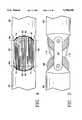
- FIG. 1Aillustrates an overall view of the master robot of the present invention
- FIG. 1Billustrates an overall view of the slave robot of the present invention
- FIG. 2illustrates a side view of the general decoupled robot joints of the present invention
- FIG. 3illustrates a top view of FIG. 2
- FIG. 4illustrates a top view of one embodiment of the decoupled joints with cable driven actuation
- FIG. 5illustrates a side view of FIG. 4
- FIG. 6illustrates a cut-away side view of FIG. 5
- FIG. 7illustrates a cross sectional side view of the input link of FIG. 4
- FIG. 8illustrates a cross sectional side view of the output link of FIG. 4
- FIG. 9illustrates a 90 degree deflection of the robot arm connected to the decoupled joint of the present invention
- FIG. 10illustrates a 180 degree deflection of the robot arm connected to the decoupled joint of the present invention
- FIG. 11illustrates one robot wrist which can be utilized as the preferred wrist for the slave robot 8 and an alternate wrist for the master robot;
- FIG. 12Aillustrates a side view of one antibacklash mechanism that can be used in accordance with the present invention
- FIG. 12Billustrates a front view of one antibacklash mechanism that can be used in accordance with the present invention
- FIG. 13illustrates an overview of the interaction between the sub-systems of the robot system of the present invention
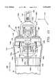
- FIG. 14Aillustrates a front cut-away view of the base of the master robot of the present invention
- FIG. 14Billustrates a left side cut-away view of the base of the master robot of the present invention
- FIG. 14Cillustrates a left side cut-away view of the base of the slave robot of the present invention
- FIG. 14Dillustrates a right side cut-away view of the base of the slave robot of the present invention
- FIG. 15is a block diagram illustrating the interconnections of the master and slave robots with the amplifier chassis and the control chassis and their respective components;
- FIG. 16is a block diagram illustrating the interaction of the servo-control sub-system and the high-level software sub-system with the mechanical sub-system and the electronics sub-system of the present invention
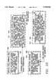
- FIG. 17is a block diagram illustrating a sample functional interface of the electronics sub-system with the mechanical and servo-control sub-systems;
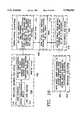
- FIG. 18is a state diagram illustrating sample transitions of the control electronics of the electronics sub-system of FIG. 17;
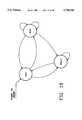
- FIG. 19Ais a kinematic axes diagram illustrating the kinematics of the master robot
- FIG. 19Bis a kinematic axes diagram illustrating the kinematics of the slave robot
- FIG. 20is a kinematic axes diagram illustrating the gear bail angels and axes of rotation
- FIG. 21is a kinematic axes diagram illustrating one of the gear bail angles and rotation due to linear actuation
- FIG. 22is a kinematic axes diagram illustrating a streamlined approach to relating the linear actuator movement e to the gear bail angle ⁇ ;
- FIG. 23is a block diagram illustrating an overview of the high-level software architecture
- FIG. 24is a block diagram illustrating the specific interaction between the workstation and the control chassis.
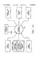
- FIG. 25is a block diagram illustrating the states and their possible transitions in the real-time high-level software architecture.
- FIG. 1Aillustrates an overall view of the master robot or input device of the present invention.
- FIG. 1Billustrates an overall view of the slave robot of the present invention.
- the input device 8functions as a master robot manipulator for a microsurgical teleoperated robot system for controlling the movement of a slave robot manipulator 8'.
- the input device 8 or master robot manipulatorcomprises an arm 10 coupled to a wrist 14.
- the wrist 14is coupled to a six-axis force/torque sensor 12 which is coupled to a stylist 13 located outboard of the sensor 12.
- the wrist 14provides an intersecting axis for pitch, yaw, and roll and is coupled to a forearm 16 which is coupled to a doubled-jointed elbow joint 18 for connecting an upper arm 20 to the forearm 16.
- the upper arm 20is coupled to a double-jointed shoulder joint 22 for connecting a shoulder 24 to the upper arm 20.
- the shoulder 24is coupled to a torso joint 26 which is coupled to an actuator base 28.
- the actuator base 28contains an antibacklash mechanism and electrical and mechanical components for receiving input from the input device 8 and transmitting the input for teleoperation.
- the electrical and mechanical componentsreceive feedback from an external device, such as a programmable processor or a torque sensor located on the slave robot of FIG. 1B, which is controlled by the input device 8.
- the electrical and mechanical componentstransmit the feedback to the input device 8.
- the forearm 16, upper arm 20, and shoulder 24all preferably have housings in the form of cylindrical casings 30.
- the torso joint 26is rotatable relative to the actuator base 28.
- the wrist joint 12has three degrees of freedom and each joint (elbow 18, shoulder 22, and torso 26) has one degree of freedom.
- the input device 8, functioning as a master robot 8has indexing capabilities. For example, during operation of the system, if the master robot 8 reaches its physical end of travel or its range of motion has reached its boundaries, but the slave robot of FIG. 1B requires further movement, the master robot 8 can be temporarily deactivated, relocated within its boundaries, and then reactivated to provide the additional movement required by the slave. Thus, the master robot 8, operating in a limited space area, can control the movement of the slave robot within an infinite area, restricted only by the physical limitations of the system.
- the slave robot manipulator 8'has six degrees of freedom and includes an arm 10' with an end effector 12' coupled to a three-axis wrist joint 14', which is coupled to a forearm 16'.
- the forearm 16'is coupled to a doubled-jointed elbow joint 18' for connecting an upper arm 20' to the forearm 16'.
- the upper arm 20'is coupled to a double-jointed shoulder joint 22 for connecting a shoulder 24' to the upper arm 20'.
- the shoulder 24'is coupled to a torso joint 26' which is coupled to an actuator base 28'.
- the actuator base 28'contains electrical and mechanical components for controlling the movements of the robot 8'.
- the forearm 16', upper arm 20', and shoulder 24'all preferably have housings in the form of cylindrical casings 30'.
- the torso joint 26'rotates the arm 10' relative to the actuator base 28'.
- the wrist joint 14'has three degrees of freedom and each joint (elbow 18', shoulder 22', and torso 26') has one degree of freedom.
- the double-jointed robot joints 18, 18', 22, 22' and the wrist joints 14, 14' of FIGS. 1A and 1Bcan be used in large automated environments, as well as micro automated environments, including microsurgical environments.
- the double-jointed robot joints 18, 18', 22, 22'will be discussed in detail below in FIGS. 2-10, the wrist joints will be discussed in detail below in FIG. 11, one antibacklash system will be discussed in detail below in FIGS. 12A and 12B, and the master and slave robots will be discussed in FIGS. 14A, 14B, 14C, and 14D.
- the entire robot systemwill be described in detail in FIGS. 15-32 below.
- the robot manipulatorcan be used in numerous environments, the preferred embodiment involves the use of the robot manipulator in a microsurgical environment.
- FIG. 2is a side view and general overview of a double-jointed, decoupled robot joint of the master or slave robot of the present invention.
- FIG. 3illustrates a top view of FIG. 2.
- the double-jointed robot jointcouples sections of respective robots 8, 8' of FIG. 1A and 1B together.
- Each double-jointed robot jointcan have internal actuators, such as an internal actuation pulley/cable system (described in detail in FIGS. 4-8) coupled to external motors located at the respective actuator bases 28, 28' of FIG. 1A and FIG. 1B or internal motors in each joint (not shown) for actuating the particular joint or other joints of the respective robots 8, 8'.
- internal actuatorssuch as an internal actuation pulley/cable system (described in detail in FIGS. 4-8) coupled to external motors located at the respective actuator bases 28, 28' of FIG. 1A and FIG. 1B or internal motors in each joint (not shown) for actuating the particular joint or other joints of the respective robot
- the double-jointed robot joint of FIGS. 2 and 3includes an input link 32 and an output link 34.
- the input link 32is on the near side of the actuator base 28 while the output link 34 is on the far side of the actuator base 28 and is moveable relative to the input link 32.
- the input and output links 32, 34are attached to each other via a pair of hinged side struts 36.
- the links 32, 34pivot about pivot points 38 and 40 at the input link 32 and output link 34, respectively. These pivot points 38 and 40 define an input axis 42 and output axis 44, respectively.
- An input keying drive component 46 and an output keying drive component 48are centered on each respective hinged axis or pivot point 38 and 40 and are attached to each respective link 32 and 34 so that they are constrained to rotate with respect to each other. This constrained rotation between the input keying drive component 46 and the output keying drive component 48 defines an instantaneous center of rotation 49 between the two keying drive components 46 and 48.
- the keying drive components 46 and 48can be fixed spur gears which mesh together or they can be fixed pulleys with wound cables as described in detail below.
- each jointhas an input passing drive component 50 rotatable about the pivot point 38 of the input link 32.
- the input passing drive component 50is coupled to an actuator (not shown) at the actuator base 28 of FIG. 1 and to an output passing drive component 52.
- the output passing drive component 52is rotatable about the pivot point 40 of the output link 34.
- the passing drive components 50 and 52can be a spur gear system or a pulley system. In a pulley system, respective passing cables passing through each respective passing drive component would be included.
- a first passing cable 54originating from another passing drive component in another joint or from the actuator base 28 of FIG. 1, travels from the input link 32, around the top of the input passing pulley 50, through the instantaneous center of rotation 49, and then around the bottom of the output passing pulley 52.
- a second passing cable 56originating from the same location as the first passing cable 54, travels from the input link 32, around the bottom of the input passing pulley 50, through the instantaneous center of rotation 49, and then around the top of the output passing pulley 52.
- This arrangementallows the input passing drive component 50 to rotate with respect to the output passing drive component 52 about the same instantaneous center of rotation 49 defined by the input and output keying drive components 46 and 48. Since the pair of passing drive components rotate about the same instantaneous center of rotation 49 as the keying drive components 46 and 48, the passing drive components 50 and 52 are kinematically decoupled from the joint's motion. This decoupling configuration allows the passing drive components 50 and 52 to actuate movement in other joints without affecting the motion of the particular joint.
- any number of pairs of passing drive componentscan be used with each joint as long as coupled pairs of passing drive components (input and output) rotate with respect to each other about the same instantaneous center of rotation defined by the keying drive components.
- FIGS. 4-10show a tendon-driven system of one embodiment of the double-jointed decoupled robot joints.
- FIG. 4is a top view and FIG. 5 is side view of tendon-driven double-jointed decoupled robot joints.
- the joint of FIG. 4is structurally similar to the joint of FIGS. 2 and 3 and includes an input link 60, an output link 62, hinged side struts 64, an input keying drive component 66, an output keying drive component 68, an instantaneous center of rotation 70 (shown in FIG. 6), input passing drive components 72, output passing drive components 74, and corresponding passing cables 76 and 78, respectively.
- FIGS. 4-10The functions of each element above has the same or similar functions as the related elements of FIGS. 2 and 3.
- the embodiment of FIGS. 4-10is different in that it is a cable or tendon-driven system and further includes an actuation mechanism. Since the embodiment of FIGS. 4-10 is a cable or tendon-driven robot, the keying drive components 66 and 68 are pulleys with corresponding cables 80 and 82, respectively, which can be stainless steel cables. Also, FIGS. 4-10 further include actuation pulleys and cables within the particular joint for actuating the joint.
- the input keying pulley 66is fixed to the input link 60 and the output keying pulley 68 is fixed to the output link 62 on respective input and output axes 84 and 86.
- the input axis 84is defined by a pivot point of the input keying pulley 66 on the input link 60.
- An output axis 86is the counterpart to the input axis 84 and is defined by a pivot point of the output keying pulley 68 on the output link 62.
- two keying cables 88 and 90are connected to the input link 60 and the output link 62, respectively.
- the keying cables 88 and 90can also be connected directly to the keying pulleys 66 and 68, respectively.
- the first keying cable 88is attached to a bottom portion of the input link 60 and winds around a top side of the input keying pulley 66, crosses to the output keying pulley 68, winds around a bottom side of the output keying pulley 68, and terminates on a top portion of the output link 62.
- the second keying cable 90is attached to a top portion of the input link 60 and winds around a bottom side of the input keying pulley 66, crosses to the output keying pulley 68, winds around a top side of the output keying pulley 68, and terminates on a bottom portion of the output link 62.
- the second keying cable 90traverses a mirrored path of the first keying cable 88. If the cables are stainless steel, the cables 88 and 90 can be terminated with solder joints or crimp terminations. However, soldered terminations are preferred because they are easy to install, take up very little space, and do not inflict an initial stress concentration in the cable, assuming the solder joint is not flexed.
- the keying pulleysare constrained to respective links similar to the keying drive component arrangement of FIGS. 2 and 3.
- the keying pulleys 66 and 68preferably have the same diameter, but this is not necessary.
- One feature of the present inventionis that the keying cables 88 and 90 cross one another between the keying pulleys 66 and 68 as shown in FIG. 6 to define the instantaneous center of rotation 70. The identical effect of having an instantaneous center of rotation can be achieved with spur gears which mesh together, in a similar manner as the keying drive components 46 and 48 of FIGS. 2 and 3.
- the present inventionis preferably a tendon-driven system consisting of keying cables 88 and 90 and keying pulleys 66 and 68 instead of spur gears.
- Each double-jointed robot jointhas one degree of freedom.
- Each joint's rotationis dependant on the ratio of the keying pulleys' 66 and 68 diameters. For example, if both keying pulleys 66 and 68 have the same diameter, the angle that the output link 62 is moved relative to the input link 60 will be exactly twice the angle between the side struts 64 and each link 60 and 62. In other words, if the output link 62 is rotated 90° to the input link 60, the side struts 64 will rotate 45° to each link 60 and 62, as shown in FIG. 9. Likewise, the output link 62 can rotate up to 180° at which point the side struts 64 will be at 90° to each link 60 and 62, as shown in FIG. 10.
- the distance between the input and output axesmust be at least equal or greater than an effective diameter 92 of each links 60 and 62, as shown in FIG. 10. It is important to note that the 180° range of motion is bidirectional, thus the full range of joint motion is 360°. Alternatively, if the keying pulleys 66 and 68 have different diameters, other kinematic relationships can be achieved between the input link 60, output link 62, and side struts 64 without affecting other features of the robot.
- FIGS. 7 and 8are cross-sectional views through the input and output axes, respectively.
- the jointcan be actuated by two input dual actuation pulleys 94 and 96.
- Each input dual actuation pulley 94 and 96includes transmission pulleys 98 and 100 and connecting pulleys 102 and 104, respectively.
- the two input dual actuation pulleys 94 and 96sandwich the input keying pulley 66 on the input axis 84 as shown in FIG. 7.
- the actuation pulleys 94 and 96rotate independently of the input keying pulley 66.
- each of the connecting pulleys 102 and 104have corresponding actuation cables 110 and 112 terminated to it.
- the transmission pulleys 98 and 100have transmission cables 114 and 116 coupled to the actuator base for actuating the pulleys 94 and 96.
- the first actuation cable 110can be terminated to a top side of the connecting pulley 102 of the first input actuation pulley 94 and the second actuation cable 112 can be terminated to a bottom side of the connecting pulley 104 of the second input actuation pulley 96.
- the first actuation cable 110travels from the first input actuation pulley 94, winds around a top side of the first output actuation pulley 106, and terminates to a bottom side of the output link 62.
- the second actuation cable 112travels from the second input actuation pulley 96, winds around a bottom side of the second output actuation pulley 108, and terminates to a top side of the output link 62.
- Connecting pulleys 102 and 104can have the same diameters of actuation pulleys 106 and 108, but this is not necessary.
- the transmission cables 114 and 116are coupled to the transmission pulleys 98 and 100 of the input actuation pulleys 94 and 96, respectively, to actuate the output actuation pulleys 106 and 108 through the connecting pulleys 102 and 104 via the actuation cables 110 and 112.
- Motorstypically operate at high speeds with low torque.
- actuation of the robot joints by motors located at the actuator basetypically requires the motor to have low speed with high torque.
- Gear reduction at the jointsresolves this problem by reducing a motor's high speed with low torque to low speed with high torque.
- the actuation pulleys 106 and 108can incorporate gear reduction at the joints.
- stiffness of a tendon-driven mechanismis directly related to the spring constant of the cable or tendon.
- the spring constantis inversely proportional to the cable or tendon length.
- short cable pathswill yield a high spring constant which in turn produces high stiffness.
- Relatively high stiffnesscan be achieved with relatively larger diameter cables or tendons.
- a resultant gear reduction ratio of 2:1will produce a short actuation cable length and relatively high stiffness in the transmission cables 114 and 116.
- the stiffnessis related to the resultant gear ratio by a factor of the resultant gear ratio squared.
- the diameter of the transmission cables 114 and 116can be small, thereby enabling small bend radii and more compact packaging.
- the actuation pulleys/cablescan be a spur gear arrangement which would further increase stiffness.
- the use of spur gears with dual transmission path cables 114 and 116 (two transmission paths from the actuator) for the actuation pulleys/cableswould not induce backlash into the robot manipulator system. This is because the dual transmission paths are tied together at the actuator of the actuator base of FIG. 1 and the output link only.
- the tension in the transmission paths defined by the transmission cables 114 and 116will automatically preload the actuation cables 110 and 112. Further, if the actuation cables 110 and 112 were replaced with a spur gear train, preloading would likewise occur due to this dual transmission path arrangement.
- the joint of the robot manipulator of the present inventionalso includes an idler pulley/passing cable system.
- Passing cables 76 and 78 of passing pulleys 72 and 74pass through a particular joint to actuate other joints of the robot manipulator, thereby mechanically decoupling the particular joint's motion from the other joints' motion.
- the passing cables 76 and 78pass through the joint over input idler pulleys 120 and output 126 idler pulleys.
- the input idler pulleys 72 and 120 and output idler pulleys 74 and 126rotate freely about the input axis 84 and output axis 86, respectively.
- the robotcan have an unlimited number of idler pulleys and corresponding passing cables.
- corresponding input 72 and output 74 idler pulleysmust have the same diameter ratio as that of the input 66 and output 68 keying pulleys, respectively. For example, if the keying pulleys 66 and 68 have equal diameters (1:1 ratio), the idler pulleys 72 and 74 for a corresponding passing cable 78 must have equal diameters (1:1 ratio), or coupling will occur. The absolute size of the idler pulleys 72 and 74 have no consequence.
- the second constraintis that the passing cables 78 must follow the same path as the keying cables 88 and 90 and define the same instantaneous center of rotation 70 as the keying cables 88 and 90. Namely, the passing cables 78 must cross from the idler pulleys 72 on input axis 84 to the idler pulleys 74 on the output axis 86 at the same location the keying cables 88 and 90 cross. As a result, as the joint rotates, the amount of passing cable 78 that is wound onto one idler pulley 72 on the input axis 84 equals the amount of passing cable 78 that is unwound off the idler pulley 74 on the output axis 86.
- the keying pulleys 66 and 68do not rotate relative to their corresponding links 60 and 62, and the passing cables 78 are cabled via the same scheme as the keying cables 88 and 90, the idler pulleys 72 and 74 are stationary relative to the links 60 and 62. This produces complete decoupling of the joint and the passing cables 78. Further, there is no restriction (other than physical packaging) to the amount of passing cables 78 that can be passed through a particular joint.
- the passing cables 78 path lengthsare constant throughout the entire range of travel. Depending on the idler pulley 72 and 74 diameters, it may be necessary to confine the passing cables 78 to prevent lifting off their corresponding idler pulleys 72 and 74. Confinement can be accomplished by wrapping the passing cables 78 completely around the corresponding idler pulleys 72 and 74, or by adding idler pulleys (not shown) inside the links 60 and 62.
- the first constraintis that two sets of independent idler pulleys, each consisting of an input idler pulley and an output idler pulley, are needed for each path of cable.
- the second constraintis that the passing cables 78 must be arranged in such a way that they will align to idler pulleys on the next perpendicular joint. In other words, all the passing cables 78 on their respective idler pulleys of a particular joint must align smoothly onto the idler pulleys of a connecting joint.
- FIGS. 7 and 8illustrate one embodiment to achieve smooth alignment.
- a first set of passing cables 78are arranged on incrementally smaller idler pulleys to form a 45° imaginary line 132 on one side of the keying pulley.
- a second set of passing cables 76are symmetrically arranged on incrementally smaller idler pulleys about the joint's center to form a 45° imaginary line 130 on an opposite side of the keying pulley.
- the jointcan be rotated at 90° increments and still align with the previous joint.
- Other angular incrementscan be achieved by positioning the passing cables in other configurations as long as all the passing cables on their respective idler pulleys of a particular joint are aligned smoothly onto the idler pulleys of a connecting joint.
- FIG. 11illustrates one robot wrist which can be utilized as the preferred wrist for the slave robot 8 and an alternate wrist for the master robot.
- the robot wrist 134includes an input assembly 135A, an output assembly 135B, an inner housing 138, an outer housing 139, a middle housing 140, an input shaft 141, an output shaft 142, and a linkage assembly 143.
- the input and output assemblies 135A, 135Bdefine a dual universal joint system that provides a three degree of freedom, singularity free, mechanically decoupled joint that operates in a full hemisphere of motion (up to 90 degrees in any direction).
- the input assembly 135Aincludes an input outer universal 136A and an input inner universal 137A.
- the output assembly 135Bincludes output outer and inner universals 136B, 137B which are counterparts of the input universals 136A, 137A.
- Each input universal 136A, 137Ais symmetrical to its output universal 136B, 137B counterpart, respectively.
- the corresponding counterparts, defined by the symmetrical arrangement,are rotatably coupled to each other.
- the input and output universalsare preferably coupled to each other by a tendon or cable arrangement (not shown) along a longitudinal axis parallel to an x axis.
- the universalsare U-shaped and have arcuate faces on opposing input and output sides.
- the U-shaped configuration of the outer universals 136A, 136Bdefine a respective slot for slidably receiving the input and output shafts 141, 142, respectively.
- Both outer and inner universalsterminate in a pair of the arcuate faces.
- the arcuate faceshave holes (not shown) for mounting the cables (not shown) between respective input and output outer universals 136A, 136B.
- each inner universal 137B, 137Bterminates in a pair of the arcuate faces.
- the inner universal facesalso have holes (not shown) for mounting the cables (not shown) between respective input and output inner universals 137B, 137B.
- the input universals 136A, 136Brotate on the respective arcuate faces about the output universals 137B, 137B, to define an instantaneous center.
- each set of universalsis functionally similar to the keying pulley/cable arrangement of FIGS. 4-8.
- the input universals 136A, 137Aare fixed to an input origin A and the output universals 136B, 137B are fixed to an output origin B.
- Each input and output origin, A, Bconsist of two orthogonal axes about the y and z axes.
- a set of outer universal cables(not shown) couples the input outer universal 136A to the output outer universal 136B.
- a set of inner universal cables(not shown) couples the input inner universal 137A to the output inner universal 137B.
- the outer universal set of cablesis aligned perpendicularly to the inner universal set of cables.
- the outer and inner universal cablesare preloaded (in accordance with the discussion below in FIGS. 14A and 14B) in order to eliminate backlash in the y and z axes.
- the outer and inner universal cablesare preferably steel cables.
- each pair of coupled universalsrotate with respect to one another about a defined instantaneous center, similar to the input and output keying pulley arrangement of FIGS. 4-8.
- the instantaneous center of FIG. 11has two axes of rotation, namely the y and z axes, unlike the instantaneous center of FIGS. 4-8 which has only one axis or rotation. The rotational movements of the universals about their respective axes will be discussed below in detail.
- the inner housing 138has two halves, each being defined by two pairs of symmetrical crowns 138', 138". Each crown 138', 138" has four holes (not shown) centered on respective input and output origins A, B.
- the input universals 136A, 137Aare rotatably mounted in the holes in each crown 138', 138" on the input origin A via bearings (not shown).
- the output universals 136B, 137Bare rotatably mounted in the holes in each crown 138', 138" on the output origin B via bearings.
- the output shaft 142is rotatably coupled to the output inner universal 137B at the origin point B at the inner housing 138.
- the input shaft 141is rotatably coupled to the input inner universal 136A at the input origin point A at the inner housing 138. This arrangement enables rotation of the input and output shafts 141, 142 about the y axis.
- the input and output shafts 141, 142are coupled to the input and output inner universals 137A, 137B, respectively, with bearings (not shown).
- the inner universals 137A, 137Bare rotatably coupled to the inner housing 138 at the z axis.
- the output shaft 142slides within the slot defined by the U-shaped configuration of the output outer universal 136B along the y axis.
- the input shaft 141slides within the slot defined by the U-shaped configuration of the input outer universal 136A along y axis. This arrangement enables the input shaft 141 to rotate around the z axis and move the output inner universal 137B. Rotation of output shaft 142 around the y axis results in no movement of the output inner universal 137B. However, rotation of output shaft 142 around the y ax is results in movement around the y axis of the output outer universal 136B.
- the outer housing 139is rotatably coupled to the middle housing 140 via a bearing assembly (not shown).
- the middle housing 140is rotatably coupled to the inner housing 138 via a second bearing assembly (not shown). This enables rotation about the x axis between both the inner housing 138 and the middle housing 140 and the outer housing 139 and the middle housing 140. Thus, middle housing 140 rotates relative to inner housing 138 and outer housing 139.
- the bearing assembliesare concentric and are nested inside one another. This concentric configuration allows both bearings to be assembled simultaneously, for easy assembly at any scale.
- the rotation of the input shaft 141is transmitted through the housings and the universals to the output shaft 142 so that bidirectional rotation of the input shaft 141 results in bidirectional rotation of the output shaft 142.
- An actuator(not shown), which can be located in the forearm 16, rotates the input shaft 141 about the x axis (roll axis).
- the linkage assembly 143provides movement about the y and z axes of the output shaft 142 simultaneously.
- the linkage assembly 143includes four links 144a, 144b, 147a, 147b, each having hooked ends (not shown).
- the links 144a, 144bare pivotally coupled about the y and z axes by a ball socket (not shown) at corresponding link attachments 145a, 145b, via the hooked ends.
- the link attachments 145a and 145bare rigidly attached to the middle housing 140.
- the links 147a and 147bare attached in a similar manner to the outer housing 139. Movement of the links 144a, 144b in the general direction of arrows 146 causes rotational movement of the inner housing 138 about the z axis of the wrist 134.
- Movement of the links 147a, 147b in the general direction of arrows 146results in rotational movement of the inner housing 138 about the y axis of the wrist 134. Any displacement of inner housing 138 relative to input shaft 141 is mirrored on output shaft 142 relative to inner housing 138. Hence, there is a 2:1 amplification of movement of output shaft 142 over inner housing 138. This enables a full hemisphere of motion.
- the links 144a, 144b, 147a, and 147bare confined to move in the x-y plane. Each link 144a, 144b, 147a, 147b is connected to a corresponding linear carriage (not shown).
- the linear carriagesare located within the forearm 16 and are fully symmetrical. Each linear carriage moves the corresponding link attached to it in a back and forth direction as indicated by arrow 146.
- the linear carriagesare coupled and actuated by actuators (not shown) located in the forearm 16 or base.
- the linear carriagesinclude a 2:1 force multiplier that counteracts a 2:1 force divider inherent to the kinematics of the system. Inclusion of the 2:1 force multiplier increases the stiffness of the wrist 134 by a factor of four.
- Corresponding linear carriagesactuate links 144a and 147a in opposition to links 144b and 147b in order to actuate the z and y axes, respectively. Also, the linkages inherently preload one another, thereby eliminating their source of backlash.
- the wrist 134provides movement about the x, y, and z axes simultaneously.
- the wrist 134provides up to 180 degrees of motion about the y and z axes for the output shaft 142.
- the input shaft 141is bidirectionally rotatable 360 degrees simultaneous with movement about the y and z axes.
- the work envelope of the wristis a full hemisphere of motion.
- An end cap 148guides and positions the input shaft 141 and links 144a, 144b, 147a, 147b within the forearm 16.
- the input shaft 141can be rotated inside the forearm within a ring bearing (not shown).
- the input shaft 141can be coupled to a pulley assembly (not shown) within the forearm 16.
- This pulley assemblycan be coupled to an actuator (not shown) located either within the forearm 16 or in the actuator base of FIG. 1. The actuator would transmit movement to the pulley assembly in order to move the input shaft 141.
- the output shaft 142has an end effector 149 for holding all types of tools (not shown). Circuitry can be routed through the arm to provide power to tools coupled to the end effector 149 that require electrical or pneumatic power. Also, the tendon or cable-driven arrangement (in accordance with the antibacklash scheme described below in detail) negates backlash in two of the three axes. In addition, the wrist 134 of the present invention has low stiction, high stiffness, and high strength-to-weight ratio.
- the wrist 134can be approximately one inch in diameter, weigh approximately three ounces, and have a payload of about three inch-pounds. This allows the wrist 134 of the present invention to sustain a high work volume, while being lightweight, compact, and miniature in size.
- the wrist 134 of FIG. 11is modified to exclude components 136a, 136b, and 137b.
- output shaft 142is rigidly attached to housing 138 so that output shaft 142 cannot move relative to housing 138. In other words, output shaft 142 could be excluded and housing 138 extended so that housing 138 essentially becomes the output shaft.
- the wrist 134is transformed into a standard universal joint with dual bearing rings attached to the pitch and yaw actuation links.
- This arrangementprovides decoupling of the pitch and yaw axes and allows the preferred wrist to have zero backlash in all axes.
- elimination of the aforementioned componentsprovides zero backlash in the pitch, yaw, and roll axes and also provides greater efficiency, thereby reducing friction.
- elimination of the aforementioned componentsreduces the work volume of the master robot by half.
- the actuation links of the preferred wristare activated by the tendons, which are passed through the elbow and shoulder joints to the base.
- the rollis activated by tendons which rotate the universal joint, passing rolling motion to a face plate located at the end of the wrist.
- the face plateallows for attachment of various components, such as variations of the stylus 13 shown in FIG. 1, depending on the application.
- the tendons controlling the pitch and yaw axespass through the elbow and shoulder joints, and exit the base housing.
- FIGS. 12A and 12Billustrate the preferred antibacklash mechanism of the slave robot 8' of FIG. 1B.
- the input device or master robot 8 of FIG. 1Autilizes a standard single stage antibacklash mechanism.
- the antibacklash mechanism of the FIGS. 12A and 12Bcan be used in the master robot 8.
- the antibacklash mechanism 154are used with the joints of FIGS. 2-11 to overcome the problems of conventional antibacklash schemes.
- the antibacklash mechanismis incorporated in the respective robots 8, 8' between the actuators, such as motors 156 at the actuator base, and an output 157 or the device to be actuated, such as the output link 62 of FIG. 5 of a particular joint.
- the antibacklash mechanism 154is a multiple stage device not limited to any particular number of stages.
- the antibacklash mechanism 154utilizes a drivetrain system 158 with drive components such as gears, belts, and/or cables.
- FIGS. 12A and 12Billustrate the antibacklash mechanism 154 having three stages 160, 162, and 164 with a pair of gears 166 and 168 and 170 and 172 at the first 160 and second stages 162, respectively.
- Two independent transmission pathsdefined by the gears 166, 182, 170, and 168, 184, 172, are formed as two identical geartrains in parallel for each drive.
- a given joint's motor 156would have one spur pinion 178 on its shaft 180 which would engage with two independent gears 166 and 168 of the first stage 160.
- the two independent transmission pathsare mechanically coupled only at an input, such as the motor 156, and an output, such as an actuation pulley located on a particular joint.
- the first and second stage gears 166 and 168are free to rotate independent of each other, respectively.
- the pinion 178 on the motor 156 at the inputdrives both of the independent first stage gears 166 and 168 to complete a first stage 160 reduction.
- Two second stage 162 pinions 182 and 184are rigidly attached to each of the first stage gears 166 and 168, for example on a gear shaft.
- the two second stage 162 pinions 182 and 184drive the two independent second stage gears 170 and 172, thus completing the second stage 162 reduction (additional gear stages can be used).
- Each of the second stage gears 170 and 172drives an independent actuation drum or tendon spool 186 and 188 on a common shaft.
- Two cables 190 and 192each attached to one of the spools 188 and 186, terminate on the output, which can be for example the actuation pulleys 106 and 108 of FIGS. 4-11.
- the cables 190 and 192actuate the particular joint, thereby completing the third stage 164 and completing a dual drive system 174 and 176.
- the only common points between the dual drive system 174 and 176are at an origination at the input 156 (i.e. the motor 156) and the termination at the output 157 (i.e. the actuation pulleys 106 and 108 at the joint).
- the dual drivetrain systemis preloaded by first disengaging the motor 156 from the first stage 160 gears 166 and 168 so that the two gears 166 and 168 can be counter-rotated relative to one another. This counter-relation preloads the cables 190 and 192 to the desired tension. This rotation passes from stage to stage until all the cables become tensioned. When the desired preload tension is achieved, the motor 156 is simply re-engaged and the preload is locked.
- the two drivetrains 174 and 176can be reloaded relative to one another if necessary.
- the value of the preloadis proportional to any gear ratios between the stages 160, 162, and 164.
- an optimum preloadis achieved automatically in all the stages 160, 162, and 164 simultaneously because the preloading is passed via the gearing from the input motor 156 to the output 157.
- This preloadis transmitted throughout the entire dual drivetrains 174 and 176, thereby eliminating backlash in all drivetrains.
- the preloadis transmitted proportionately to the gear ratio for each stage, to optimize the preload for maximum mechanical efficiency, unlike the prior art where each stage is independently preloaded.
- the antibacklash mechanism 154 of the present inventionprovides geartrains with zero backlash, convenient preload adjustment, preload adjustment of all stages simultaneously, and stage preload proportional to stage ratio to achieve maximum mechanical efficiency. Also, since the required gear ratio for the microsurgical robot manipulator described above is between the actuator and each joint, the antibacklash mechanism of FIGS. 12A and 12B is global for all the joints and encompasses a wide range of ratios. In addition, for the cable-driven robot manipulator, the cable preload is adjustable to accommodate stretching over time.
- FIG. 13illustrates an overview of the interaction between the sub-systems of the robot system of the present invention.
- the input device 8functions as a master robot in a microsurgical teleoperated robot system.
- the overall system architectureincludes a slave robot manipulator 8' coupled to an amplifier chassis 202.
- the amplifier chassis 202is coupled to a control chassis 204, such as a VME chassis, which is coupled to a workstation 206, such as a UNIX workstation via standard twisted pair Ethernet 208.
- the workstationhas a graphical user interface 210 which can have a keyboard or other input device for ease of control by a user.
- the amplifier chassis 202is coupled to the motors of the master robot manipulator 8 and the control chassis 204 is coupled to the encoders of the master robot manipulator 8.
- a force feedbackcan be applied to the input device 8 and can be generated from the slave robot 8'. This would enable a user to operate the slave robot 8' via the input device 8 without physically viewing the slave robot 8'. Also, the force feedback can be generated from the workstation to represent fictitious forces. These fictitious forces are very desirable because they can constrain the input device's 8 control of the slave robot 8' to be within imaginary predetermined boundaries.
- the subsystemsinclude the mechanical sub-system, the electronics sub-system, the servo-control sub-system, and the high-level software control sub-system. These sub-systems are described in detail in sections that follow.
- FIG. 14Aillustrates a front cut-away view of the base of the master robot of the present invention
- FIG. 14Billustrates a left side cut-away view of the base of the master robot of the present invention.
- the base 28houses components that control the arm.
- the arm 10is mounted to the actuator base 28 which can be a cylindrical base housing.
- the base housingis preferably about 23 cm long, 18 cm wide, and 10 cm high.
- the tendons passing through the arm 10 of FIGS. 4-8enter the base 28 through a connection between the arm 10 and the base 28.
- the tendonsare wound on five independent tendon spools (not shown), one for each axis (the shoulder 22 axis, the elbow 18 axis, and the pitch, yaw, and roll axes of the wrist 14).
- the torso 26rotates relative to the base 28 about a sixth axis and is driven by gears (not shown).
- the tendons of the other five axesare twisted about their length along the sixth axis.
- this arrangement of the present inventionproduces decoupling, it does vary the tension in the tendons by a small percentage ( ⁇ 1%). Also, as a result, travel of the sixth axis is restricted to approximately 30 degrees. However, since the input device 8 has indexing capabilities, a high range of motion is not necessary.
- Each of the six axesis equipped with a high-resolution optical encoder 151 (for a total of six encoders), such as an encoder capable of 40,000 counts per revolution.
- the six encoders 151are housed in the base 28 and are necessary for reducing the amount of gearing necessary to achieve the required positional resolution while limiting friction.
- the encoders 151are attached to the tendon spools and the torso axis via a standard single stage antibacklash geartrain.
- the antibacklash geartrain described in FIGS. 12A and 12Bmay be utilized.
- geartrain ratiosvary from about 1.25:1 on the torso 26, shoulder 22, and elbow joints 18 to as high as about 5.3:1 on the roll axis.
- the base 28also preferably includes three arm motors 153 and three wrist motors (not shown) to create the force-feedback capability on the torso 26, shoulder 22, and elbow axes 18, and the three-axis wrist 14, respectively.
- the motorspreferably have Hall effect sensors incorporated within.
- the force feedbackcan be applied to the input device 8 for providing feedback to an operator of the input device 8.
- the force feedbackcan be generated from the slave robot 8' (see FIG. 1B) which the input device 8 controls.
- the force feedbackcan be generated from an external device, such as a programmed processor, to produce fictitious forces on the input device.
- the fictitious forcescan represent desired boundaries to constrain the slave robot 8' of FIG. 1B within.
- the input device 8can produce approximately six ounces of force, and may be driven to produce approximately 13 Newtons force and about 300 N-mm of torque at the wrist. Minimizing the force output minimizes the friction and reflected inertia for a given motor.
- the motorsare preferably DC brushless motors, but could be replaced with any other type of motor. These motors are attached to the tendon spools via a standard single stage spur geartrain. Also included in the base 28 is the electrical wiring (not shown) to support the motors and encoders 151, all of which are connected to electrical connectors (not shown) at the rear of the housing for electrical interface with an external source (not shown).
- the input device 8has 6-axes of positional input with the capacity to produce 6-axes force-feedback.
- the drive motorscreate the force-feedback capability on the torso 26, shoulder 22, and elbow 18 axes.
- the plurality of high-resolution optical encoders 151reduce the amount of gearing necessary to achieve the required positional resolution while limiting friction.
- the total work volume of the input device 8is determined by the independent joint limits described above, primarily constrained by that of the torso 26 (with the aforementioned arrangement, the torso has a range of motion of approximately 30 degrees). This results in a wedge-shaped work volume, with the apex aligned with the torso axis. The positional accuracy is maintained over the entire volume.
- FIG. 14Cillustrates a left side cut-away view of the base of the slave robot of the present invention
- FIG. 14Dillustrates a right side cut-away view of the base of the slave robot of the present invention
- the base 28' of the slave robot 8'houses motors 220' with shafts 222', encoders (not shown), gears 224', pinions 226', bearings (not shown), cable spools (not shown) and other conventional components.
- the motorspreferably have Hall effect sensors incorporated within.
- the arm 10' of the slave robot 8'has tendons or cables, pulleys, and linkages located in the arm 10' and joints 14', 18', and 22' of the slave robot 8'. These components mechanically operate the end effector 12' of the slave robot 8' under control of the master robot 8 of FIG. 1A.
- the slave robot 8'is preferably a compact six degree of freedom tendon-driven robot having very precise relative positioning capability (down to 10 microns) as well as a very high work volume.
- the arm 10'measures 2.5cm. in diameter and is 24.6 cm long from the actuator base 28' to a tip of the end effector 12'.
- the arm 10'is mounted to the actuator base 28' which can be a cylindrical base housing measuring 12.0 cm in diameter by 18.0 cm long.
- the double-jointed decoupled cable or tendon-driven joints described in FIGS. 4-10are used in the slave robot 8'. As shown in FIGS. 4-10, the joints 18' and 22' have very high ranges of motion, are double-jointed, and can pass any number of tendons through which are completely mechanically decoupled from the particular joint's motion.
- Each degree of freedom of the robotis actuated by its own motor, such as a D.C. brushless motor encapsulated inside a sterile housing.
- motors 220'there are six motors 220'(six degrees of freedom), three for the slave wrist joint 14', one for elbow joint 18', one for the shoulder joint 22', and one for the torso joint 26', which rotates the shoulder 24' about the actuator 28' or torso.
- the motors 220'are coupled to the gears 224' directly or via the pinions 226' for operating the gears 224'.
- the gears 224' and pinions 226'are spur gears to define spur drivetrains.
- gears 224' and pinions 226'can vary with different design considerations
- motor 220', pinion 226', and gear 224' configurations of the present inventionare preferably in accordance with the novel antibacklash system described above in detail in FIGS. 12A and 12B.
- Each motor 220'is equipped with an optical encoder (not shown) on its shaft 222' for position sensing.
- the optical encoderspreferably have 512 lines per revolution and produce outputs of 2048 counts per revolution. Since the smallest incremental movement during microsurgery is approximately 10 microns, 10 encoder counts is the minimum desirable incremental movement. As a result, one encoder count corresponds to one micron movement at the tip of the end effector 12'.
- the minimum required gear ratio for the slave wrist joint 14'is approximately 60:1, 300:1 for the elbow joint 18', and approximately 550:1 for both the torso 26' and shoulder 22'joints.
- the gear reduction of the slave robot 8' based on the tendons for each jointcan be accomplished as described above in FIGS. 4-8.
- the gear reductionis approximately 2.5:1 in the torso joint 26', wrist pitch, and wrist yaw axes (see FIG. 11), and approximately 1.5:1 in the shoulder 22' and elbow 18' joints, and the wrist roll axes (see FIG. 11).
- the slave robot 8'has multi-stage spur drivetrain gear reductions based on the multi-stage gearing arrangement in the antibacklash scheme of FIGS. 12A and 12B described above in detail.
- the slave wrist pitch, yaw, and roll axesall have two-stage spur reductions of approximately 37:1, making the total reduction ratios approximately 92:1 (2.5 tendon gear reduction multiplied by 37 multi-stage gear reduction) for the wrist pitch and wrist yaw axes and approximately 60:1 (1.5 tendon gear reduction multiplied by 37 multi-stage gear reduction) for the roll axis.
- the torso 26' and elbow 18' joints of the slave robot 8'all have three-stage spur reductions of about 269:1, whereas the shoulder joint 22' has a three-stage reduction of about 411:1.
- the resulting total reduction ratios for the slave robot 8'are approximately 667:1, 614:1, and 370:1 for the torso 26', shoulder 22', and elbow joints 18', respectively.
- the microsurgical slave robot 8' of the present inventioncan be autoclaved for sterilization. Since the motors 220' and optical encoders are not capable of surviving such an environment, these components are removably attached within the actuator base 28'. The motors 220' and optical encoders can be removed prior to sterilization and reinstalled afterwards. The motors 220' are removably attached on two mounting blocks 230' within the actuator base 28' on alignment pins (not shown). Each mounting block 230' contains three motors. The motors 220' are coupled to an electrical power source (not shown) via an electrical connector (not shown). The housing of the actuator base 28' tightly encloses the base 28' with screw mounts (not shown) or quick-release latches (not shown).
- the slave joints 14', 18', and 22' of the microsurgical slave robot 8'require high stiffness.
- relatively larger diameter tendon cables with short path lengthsare used as described in FIGS. 4-8 above.
- low stiction(stick/slip characteristic) is needed to achieve precise motions, especially since the optical encoder position sensors are in the slave robot's 8' base 28'.
- Low stictionis accomplished by using precision ball bearings (not shown) in every rotating location, such as in all of the pulleys, joint axes, and drive shafts, to eliminate metal-to-metal sliding contact.
- the arm 10'has a large work volume so that the actuator base 28' will not have to be repositioned frequently during tasks.
- the torso joint 26'is capable of rotating the shoulder 24' 360 degrees of full rotary motion about the y axis.
- the elbow joint 18' and the shoulder joint 22'are capable of 360 degree limited rotary motion about the z axis.
- the wrist joint 14'is capable of motion about the x, y, and z axes (as described in FIG. 11 above).
- the wrist joint 14'Since each axis is completely decoupled from the joint's motion, the wrist joint 14' is capable of 180 degrees motion about the y and z axes (pitch-and-yaw motion) and 540 degrees of continuous motion about the x axis (roll motion) and thus, operates in a full hemisphere of motion.
- FIG. 15is a block diagram illustrating the interconnections of the master and slave robots with the amplifier chassis and the control chassis and their respective components of the servo-control sub-system.
- the amplifier chassis 202can contain, for example, slave robot motor drive amplifiers 250 for each corresponding motor of the slave robot 8', master robot motor drive amplifiers 252 for each corresponding motor of the master robot 8, a system control electronics board 254, and an amplifier power supply 256.
- the amplifier chassis 202is coupled to the VME chassis 204 (with for example, analog inputs and control signals), the slave robot 8' (with for example, motor drive signals), the master robot 8 (with for example, motor drive signals) and to an electronics sub-system 306, as shown in below in FIG. 16.
- the electronics sub-system 306comprises control electronics 275 and controls typical commands such as panic stop, run, and initialize. These commands can be monitored with a control panel 277 with visual indicators, such as light emitting diode (led) indicators.
- the electronics sub-systemwill be discussed in detail below.
- the amplifier chassis' 202 main poweris provided by the VME chassis 204 and is preferably alternating current (AC).
- Individual amplifiers 250, 252are preferably secured to the amplifier chassis 202. This provides a thermal path to the amplifier chassis 202 and also provides a favorable orientation with respect to the amplifier chassis' 202 air flow pattern to allow individual amplifiers 250, 252 to run cool.
- a frame (not shown) of the amplifier chassis 202contains all necessary amplifier interface wiring. This allows the amplifier chassis 202 to be highly modular and to facilitate rapid check-out and trouble-shooting.
- the control electronics board 254has a braking function for holding the motors in place when they are not under control of the amplifier chassis 202.
- the VME chassis 204can be comprised of many suitable configurations capable of performing the above.
- the VME chassis 204can house a VME backplane 256 with two Motorola MVME-167 computer boards 258, Proc0 and Proc1, for high level system control, master and slave servo control boards 260, 262, such as Delta Tau Data Systems, Inc.'s PMAC boards, and power supplies (not shown).
- the PMAC boardspreferably receive two channel quadrature outputs from the encoders of the master and slave robots 8, 8', respectively.
- the PMAC boardspreferably receive backup motor position information from the Hall effect sensors built into the motors of the master and slave robots 8, 8', respectively.
- Proc0performs kinematic, communication and high-level control functions. Calls to subroutines that read and set joint angle positions of the robot are made from the high-level real-time software on Proc0. These routines, through shared memory implemented between Proc0 and Proc1, provide setpoints and read current joint angles of the robot. Proc1, in turn, passes the setpoints for controlling the robot to the servo control board and retrieves the joint angles measured by the servo-control board.
- the VME chassis 204also can include supporting master and slave interface boards 264, 266, front and rear panels 268, 270, and master and slave input/output blocks 272, 274.
- the front panel 268can have a main power control (not shown) provided by alternating current (AC) and the rear panel 270 can control communication access with the workstation 206.
- the PMAC servo boards 260, 262can generate two phase drive signals for sinusoidal commutation of the systems brushless DC motors.
- the PMAC boards 260, 262receive optical encoder feedback from the motor shafts and provides low level control of the motors.
- the input/output blocks 272, 274 and interface boards 264, 266can control signal and power distribution to the rear panel 270 of the VME chassis 204.
- the servo-control sub-systemprovides digital sine-wave commutation, automatic trajectory generation, shared memory interface, built-in amplifier/encoder interface, and robust closed loop control.
- FIG. 16is a block diagram illustrating the interaction of a servo-control sub-system 300 and a high-level software sub-system 302 with a mechanical sub-system 304 and an electronics sub-system 306 of the present invention.
- the servo-control sub-system 300is partly hardware and partly software.
- the relevant hardware components of the servo-control sub-systemare amplifier cards within the amplifier chassis 202 and the controller boards on the VME chassis 204.
- Softwareruns under an operating environment, such as VxWorks operating environment, on the MVME167 boards of the VME chassis 204 to perform certain functions. These functions include setting-up control parameters and running a servo-loop on the PMAC boards, to control the six motors 220, implementing communication between the MVME167 and PMAC boards, initializing the servo-control system and communicating with the electronics sub-system, and communicating with a high-level software sub-system.
- the high-level software sub-systemresides on the UNIX workstation 206 and on the Proc0 board on the VME chassis 204.
- the high-level software sub-system 302is connected to the user interface 210 and controls initialization of the software and hardware. Also, a communication system 310, which can be based on the UNIX socket protocol or Real-time Innovation, Inc.'s Network Data Delivery System (NDDS), connects the UNIX host to Proc0. This high-level software sub-system 302 implements a number of demonstration modes 312 of robot control and computes forward and inverse kinematics and desired joint positions.
- NDDSNetwork Data Delivery System
- a first servo-control software module 314is implemented on Proc1, is coupled to the high-level software through the backplane of the VME chassis with the use of shared memory between Proc0 and Proc1.
- the first module 314configures and downloads PMAC software, accepts the desired joint positions from the high-level software and communicates these positions to the PMAC boards, and reads the actual joint positions and sends these positions to the high-level software.
- a second module 316 of the servo-control sub-systemperforms joint servo-control for all the joints based on the reading of the actual joint positions.
- the electronics sub-system 306is coupled to the servo-control sub-system 300 and will be discussed below.
- the mechanical sub-system 304is coupled to the electronics sub-system 306 and has a mode 320 which moves robot joints according to voltage commands from the electronics sub-system and returns encoder readings to the electronics sub-system.
- FIG. 17is a block diagram illustrating a sample functional interface of the electronics sub-system with the mechanical and servo-control sub-systems.
- the electronics sub-systemincorporates sophisticated control electronics 275 to provide control of the power to the motors/amplifiers during power up and power down events.
- FIG. 18is a state diagram illustrating sample transitions of the control electronics of the electronics sub-system of FIG. 17. After power on, the system can halt, fault, or run, depending on the circumstances. The transitions between the conditions are shown in FIG. 18.
- the control panel 277provides remote access to switches and indications needed to operate the robot system. For instance, the control panel 277 can have a PANIC STOP switch to halt operation quickly.
- the control electronics 275requires inputs from an operator in order to apply power to the motor amplifiers. Further, indicators, such as, RUN and FAULT led indicators show the current status of the control electronics 275.
- an operatorturns on AC power (or resets the power) from the VME chassis 204 in order to power the VME chassis 204 and the power supply 256 in the amplifier chassis 202.
- Thisalso provides power to the control electronics 275.
- the motors of the master and slave robots 8, 8'are held in a brakes-on condition.
- the RUN led indicator of the control panel 277is in an off position and the FAULT led indicator is in an on position.
- the FAULT led indicatorwill either turn off, indicating no faults, or stay on, indicating that a fault condition exists. If the FAULT led indicator turns off, then the operator can press and release a RUN switch (the RUN led indicator led turns on) to start a power up sequence. At this point, the robot is ready for computer control.
- the sequence of events leading up to a running systemare as follows: First, the control logic monitors two high priority inputs constantly, a PANIC STOP switch and a PMAC heartbeat signal.
- the PANIC STOP switchis the operator kill button to freeze motion of the slave robot 8' if an error is observed.
- the PMAC heartbeat signalis a low frequency, preferably 10 Hz, step signal sent by the PMAC boards to the control electronics 275. The signal will not step if failures of the PMAC or MVME-167 boards occur. If the PANIC STOP switch is not in the closed position then a fault is recognized. If the PMAC heartbeat signal is not received then a fault is recognized. In a fault condition the FAULT led turns on and a fault signal is sent to the PMAC servo board. If the system is running, it will stop and brake.
- a request to runis initiated when the operator presses and releases the RUN switch on the control panel 277.
- the control electronics 275releases the brakes. If one or more of the brakes does not engage, then a fault exists, and the sequence is aborted and the FAULT led indicator turns on.
- the electronics sub-system 306provides intelligent control of the main power-up and power-down events and the amplifier power-up and power-down events.
- the kinematic computationsare for each combined manipulator formed by the wrist, together with the articulated mechanism, consisting of torso, shoulder, and elbow joints, that supports the wrist.
- the followingprovides a kinematic analysis of the slave and master wrists. In particular, velocity transformations are provided, that are necessary to relate the incremental movement in the bail angles of the wrist to the corresponding movement in the universal joints of the wrist.
- the present inventionuses kinematic algorithms for computation of the forward and inverse kinematics of the robot.
- Kinematic algorithmsare described in U.S. Pat. No. 5,303,384, the disclosure of which is incorporated by reference in its entirety.
- the forward kinematics computationrefers to the determination of the tip position and orientation given known joint angle positions of the robot.
- the inverse kinematicsis the determination of the joint angle positions given a desired tip position and orientation.
- FIG. 19Ais a kinematic axes diagram illustrating the kinematics of the master robot.
- FIG. 19Bis a kinematic axes diagram illustrating the kinematics of the slave robot.
- Each angle of each jointis represented by ⁇ (k).
- ⁇ (5)is the pitch angle of rotation of the FIRST ELBOW JOINT about the pitch axis.
- ⁇ (4)is the pitch angle of rotation of the SECOND ELBOW JOINT about the pitch axis.
- ⁇ (10)is the roll angle of rotation of the TORSO about an axis perpendicular to the base of the manipulator.
- ⁇ (9)is the pitch angle of rotation of the FIRST SHOULDER JOINT about the pitch axis.
- ⁇ (8)is the pitch angle of rotation of the SECOND SHOULDER JOINT about the pitch axis
- the matrix A*(k)transforms any arbitrary vector, expressed in the coordinate system attached to the k+1 link, to the coordinate system attached the k link.
- This matrixis the transpose of the matrix A(k), which transforms a vector in a coordinate frame attached to link k into a vector expressed in a coordinate frame attached to link k+1.
- the manipulatorsare composed of a series of links.
- the links' lengthscan vary, but several of the link lengths are preferably zero.
- these "links"are actually fictitious because they correspond to the joints that have more than one degree of freedom.
- These jointsoccur at the universal joints of the wrist.
- the wrist universal jointhas 3 coincident joints.
- the first universal jointis made up of 3 coincident joints, whereas the second universal joint has 2 coincident joints.
- the compound multi-degree-of-freedom jointscan be replaced by an equivalent sequence of single-degree-of-freedom joints. With this arrangement, the distance between consecutive joints vanishes because the joints coincide.
- the following algorithmcomputes recursively the attitude matrix of a coordinate system attached to the tip of the manipulator, as well as the location of this tip.
- the tipis defined as being at a distance l(1) away from the base of the output shaft of the second universal joint, measured along the direction of this output shaft.
- the matrix Sis a 3 ⁇ 3 matrix which accumulates the products of the various transformation matrices A(k).
- the matrix Sstores the attitude matrix that transforms tip coordinates to base coordinates.
- Its transpose S*is a coordinate transformation in the opposite direction.
- the corresponding vector Lstores the location of the tip in base coordinates.
- each link kthere is a corresponding 6 ⁇ 6 transition matrix ⁇ (k,k-1) defined in terms of the link vectors L(k,k-1).
- This matrixis used to propagate quantities, in particular forces, in an inward direction from the k-1 joint to the k joint.
- Its transpose ⁇ *(k,k-1)transforms velocities in the opposite direction from the k joint to the k-1 joint.
- the transpose ⁇ *(k,k-1)is a key quantity in forming the Jacobian for the manipulator, as will be described in the next section.
- the vector L(k,k-1)is the 3-dimensional vector from joint k to joint k-1, expressed in the "local" coordinate system attached to link k. This vector is used to form the 3 ⁇ 3 matrix L(k,k-1) equivalent to the cross-product operation L(k,k-1)x.
- the transpose ⁇ *(k,k-1)is ##EQU6##
- the second column in these tablesindicate the constraints that pairs of joint angles must satisfy. These constraints result from arrangement of the preferred embodiment of the manipulators and the slave wrist.
- the two joints in each of the pairsare mechanically coupled to each other.
- To compute the Jacobianit is convenient to merge them, in the sense that the joint axis of either one of the two joints in the pair can be replaced by a new joint axis.
- This new joint axisaccounts for the effect of the other joint. For example, consider the process of combining the pair of joints 1 and 4 associated with the two pitch axes of the slave wrist. To combine these two joints, the joint axis H(1) of the first joint is replaced by the "new" joint axis H(1)+H(4) ⁇ (4,1). This new axis takes into account the effects of joint number 4.
- This merging operationis listed in the next to the last row in the table. Similar operations are listed in the table which merge the other pairs of coupled joints.
- the recursive algorithm abovecan be used to evaluate each of the columns of the Jacobian matrix.
- the rotation ⁇ (10) for the slave robot and ⁇ (8) for the master robot at the respective jointare set equal to 1, and all of the other joint velocities are set to zero.
- the recursive algorithmis used to compute the tip velocity V(0).
- the tip velocitycomputed under the assumption that the torso joint is the only rotating joint, is the 6th column of the Jacobian matrix.
- a unit rotationis assumed in the coupled slave joints 8 and 9 and in the coupled master joints 6 and 7 and all of the other rotations are set to zero.
- the merging operation H(8) ⁇ H(8)+H(9) ⁇ (9,8) for the slave and H(6) ⁇ H(6)+H(7) ⁇ (7,6) for the masterare used to merge joints 8 and 9 for the slave and joints 6 and 7 for the master into an equivalent joint axis located at the 8th slave and 6th master joints.
- the tip velocity V(0) computed under these assumptionsis the 5th column of the Jacobian. All of the other columns are computed using a similar approach, by setting the appropriate joint rates to 1, and by letting the rest of the joint rates be zero. When this is done for every joint, the evaluation of the Jacobian is completed. Inversion of the Jacobian is then be simply achieved by "calling" a matrix inversion subroutine.
- the wristpreferably consists of 2 universal joints separated by a finite length along the direction of the output shaft of the first universal joint.
- the wristpreferably consists of a single universal joint and its output shaft is the final link of the robot. The analysis below uses quantities, such as the angular velocity of the output shaft of the first universal joint, to simplify the resulting kinematics equations.
- the first universal jointrefers to the first universal joint of the wrist of the slave robot 8' and the only universal joint of the preferred wrist of the master robot 8.
- the second universal jointrefers to the second universal joint of the wrist of the slave robot 8' and does not refer at all to the master robot 8.
- the first universal joint of the wristallows 3-axis rotation with respect to the base of the wrist.
- This rotational motionis characterized by a roll, pitch, yaw sequence of Euler-type angles.
- This sequencemeans that, starting from a coordinate system attached to the base of the wrist, there is first a rotation about the roll axis, followed by two consecutive rotations about the pitch and yaw axes.
- This sequence of three coordinate transformationsare defined in terms of the universal joint angles of the wrist. They are respectively the roll, pitch, and yaw angles of an Euler-type sequence of angles.
- the unit vectors x,y,zdefine a coordinate system attached to the base of the wrist.
- One way to simplify the kinematics of the first universal jointis to use the a 1 ,a 2 ,a 3 unit vectors to define the attitude matrix
- the third column a 3 in this matrixis a unit vector in the direction of the output shaft of the first universal joint.
- the matrix Ahas a total of nine elements, usually referred to as direction cosines. These nine elements are: ##EQU8## Evolution of the Attitude Matrix:
- the attitude matrixmoves with an angular velocity ⁇ expressed in the "body" frame a 1 ,a 2 ,a 3 . This means that the columns a i of the attitude matrix satisfy
- ⁇⁇ 1 , ⁇ 2 , ⁇ 3 !.
- the angular velocity ⁇is a quantity which leads to considerable simplification, of the differential kinematics of the wrist, as outlined in the next section.
- FIG. 20is a kinematic axes diagram illustrating the gear bail angels and axes of rotation.
- the gear bail angles ⁇ and ⁇are related to the unit vector a 3 by the two equations ##EQU9##
- Equation 18has a very simple geometrical interpretation illustrated in FIG. 20. Equation 18 provides a means to go from the orientation of the output shaft, as characterized by the unit vector a 3 to the outer and inner gear bail angles ⁇ and ⁇ . In terms of the elements of the attitude matrix, ##EQU10##
- FIG. 21is a kinematic axes diagram illustrating one of the gear bail angles and rotation due to linear actuation.
- the pitch and yaw rotation of the wristis actually achieved by motion of a linear actuator which creates translation along the roll axis at the base of the wrist.
- the other gear bail angleis handled similarly.
- Table Idefines parameters used in FIG. 21.
- FIG. 22is a kinematic axes diagram illustrating a streamlined approach to relating the linear actuator movement e to the gear bail angle ⁇ and is outlined below.
- the linear actuator displacement ecauses a change in the vector b defined as
- the objectiveis to find the angle ⁇ between the vectors b and r. It should be noted that:
- Algorithm 1is used for absolute kinematics
- Algorithm 2is used for computing and inverting the Jacobian.
- FIG. 23is a block diagram illustrating an overview of the high-level software architecture.
- the componentsinclude a state transition controller (described in FIG. 25 below) and computation executions (which can include many different executions, including custom executions, depending on the application).
- Some components with computation executionsare described in application Ser. No. 08/525,813 filed Sep. 7, 1995 by Ohm et al. entitled “A DECOUPLED SIX DEGREE-OF-FREEDOM ROBOT MANIPULATOR", which application is incorporated herein by reference.
- These componentsmay be implemented in a programming language, for example, C or C++ or more easily with a real-time software development environment, such as, Real-time Innovation Inc.'s Control Shell.
- Embedded in the computational blocks of the real-time control softwareare the kinematic control algorithms.
- the kinematics of the robot system and the algorithms used to compute its forward and inverse kinematicsare described above.
- the systemis capable of demonstrating different control modes of the robot and handling operator commands in real-time, transitions between states of control, and changes in data flow due to transitions of states in the software.
- a statecorresponds to a subset of software computational modules used to perform computations for it.
- the high-level softwarehas two components, graphics user interface software 322 and real-time kinematic and control software 324.
- the graphics user interface software 322produces a graphics user interface (GUI) residing on the Unix host machine 206.
- GUIgraphics user interface
- the GUI 322interacts with the user and communicates user input to the MVME167 Proc0 board 312 through the socket interface.
- the UNIX workstation 206is coupled to the MVME167 Proc0 board in the VME chassis through, for example, an Ethernet connection, as described above in FIG. 16.
- the real-time kinematic and control software 324is implemented on the MVME167 Proc0 board 312.
- GUI 322displays buttons and sliders that the user controls using an input device, such as a mouse.
- the two components 322, 324have input and output communication channels implemented for message passing between the two components 322, 324.
- the softwarecould be, for example, using the UNIX socket utility or Real-time Innovation, Inc.'s NDDS.
- the real-time kinematic control software 324 of the high-level control softwareruns on the MVME167 Proc0 board 312 in the VME chassis and receives user commands input to the GUI 322 in real-time. Also, the real-time kinematic control software 324 switches control of the robot through a number of modes of operation. These modes of operation include manual joint control, automatic joint control, manual Cartesian control, and automatic Cartesian control. In all of these modes, servo control functions are called from the real-time software to control the robot.
- a servo-control software module 326runs on the MVME167 Proc1 board 314 in the VME chassis.
- the servo-control software module 326processes functions called by the high-level software, performs initialization of servo-control boards, sends desired joint positions to the PMAC servo-controller, reads encoder positions from PMAC servo-controlled board, and sends the information back to the high-level software.
- a servo-controller 328 resident on the PMAC boards 316performs servo-control of individual joints of the robot according to parameters set by the servo-control software module. It should be noted that the servocontrol software module and the servo-controller on the PMAC boards can have shared memory through the VME backplane.
- FIG. 24is a block diagram illustrating the specific interaction between the workstation and the control chassis.
- the real-time control software 312includes a GUI message reception and processor 323, such as the NDDS socket utility message producer described above, a state transition controller 327 with a number of states implemented corresponding to different demonstration modes of the robot, and a set of computational modules 329 that implement algorithms connected by data flow paths. Each state corresponds to a subset of the computational modules and data flow paths.
- GUI 322Commands entered into the GUI 322 are transmitted over the Ethernet connection 208 and are received by the control chassis 204. Messages are created by the message reception and processor 323. Message structure is preferably pre-defined. Each message preferably has a header code indicating the transition requested and parameters that quantify the transition.
- the NDDSis initialized. Thereafter, any GUI 322 interaction that is to generate a message to the real-time software calls a callback routine that sets up the message data structure and runs the NDDS producer 323 to produce the message.
- the messagesare broadcast from the workstation 210 to a NDDS message consumer processor 325 of the control chassis 204 via the Ethernet connection 208.
- the control chassis 204processes the messages by first having the consumer processor 325 receive and monitor the messages. Messages received are converted into a corresponding stimulus to the state transition controller 327, such as a FSM controller, with accompanying parameters defining the transition. Last, data flow and computational blocks for all possible configurations of the system are generated by the computational modules 329.
- FIG. 25is a block diagram illustrating the states and their possible transitions in the real-time high-level software architecture. Referring to FIGS. 23 and 24 along with FIG. 25, during a transition initiated by an operator of the system, set-up routines are executed and data flow paths are re-configured for the new state. Transitions in state are initiated by the operator from the GUI 322 part of the system.
- the consumer processor 325 of the real-time control software 312monitors messages received from the GUI 322 through the communication channel 208 using the NDDS protocol.
- the states implemented in the control of the slave 8' robotare: an idle state 330, a manual joint control state 332, an autonomous joint control state 334, a manual task control state 336, and an autonomous task control state 338.
- the idle state 330is where the slave robot joints are controlled to hold its current position.
- the manual joint control state 332is for implementing a manual control mode of the slave robot in joint space using the keyboard/mouse as the input device.
- the autonomous joint control state 334is autonomous repetitive sinusoidal motion in joint space exercising selected joints of the slave robot.
- the manual task control state 336is for implementing a manual control mode of the slave robot in Cartesian space coordinates using the keyboard/mouse as the input device.
- the autonomous task control state 338is autonomous repetitive sinusoidal motion exercising selected in Cartesian space coordinates of selected coordinates of the slave robot.
- the states implemented in the control of the master robot 8are: a manual joint control state 340, tip force control state 342, a sphere control state 344, a spring damper control state 346, a slave joint control state 348, and a slave task control state 350.
- the manual joint control state 340is for implementing a manual control mode of the master robot in joint space using the keyboard/mouse as the input device.
- the tip force control state 342is for implementing a manual force control mode of the slave robot in Cartesian space coordinates using the keyboard/mouse as the input device.
- the sphere control state 344is for implementing a simulated spherical wall environment around the input device that applies a force to the user's hand operating the master robot to keep the hand motions within a spherical region centered on the start position.
- the spring damper control state 346is for implementing a simulated spring/damper environment that applies forces on the user's hand operating the master robot to give it the feeling that it is moving the handle that is attached to a spring and damper in a parallel arrangement.
- the slave joint control state 348is for implementing control of the slave robot using the master device so that moving joints on the master commands motion for its corresponding joints on the slave.
- the slave task control state 350is for implementing master to slave teleoperated control so that Cartesian space motion of the master robot is replicated at the slave tip.
- the state transition that starts from the idle state 330performs initialization 351 of the servo-control system and returns to the idle state 330. This transition is performed automatically at the initialization of the real-time software set-up and is preferably not controlled manually from the GUI. Thus, when the system is initialized 351, the system returns 352 to the idle state 330.
- changes 354can be made to accommodate a user's particular input. For example, transitions from one state to another can be performed in response to messages from the GUI 322 of FIGS. 23-25. Also, transitions can be made to change states or return to the same state after a change of parameters. Further, state transition from the idle state 330 to a particular state is achieved by a goto state transition command 352. For example, a state transition that starts from the idle state 330 performs set-up of data component modules and data and re-configures the system to the desired state.
- the robotis started by powering the VME chassis, thereby initiating the down-loading and running of software on the MVME167 boards and PMAC boards.
- the GUI programis then run on the UNIX host machine to start-up the graphics user interface and establish communication between the UNIX host and the MVME167 board using the NDDS facility.
- a procedure of phasing the motorsis performed after the boot-up sequence and powering up the amplifier chassis.
- the systemis then ready for demonstrating the various control modes available. During the demonstration modes of control, the high-level software computes the desired joint positions for the robot. These are fed to the PMAC board by the servo-control software.
- the control loop within the PMAC boardreads the actual joint positions and applies the appropriate voltages to the motors to drive the joints to the desired positions.
- the motorsin turn, drive gears that rotate the spools of cables on the robot so that the joints move in the desired motion.
Landscapes
- Engineering & Computer Science (AREA)
- Health & Medical Sciences (AREA)
- Robotics (AREA)
- Surgery (AREA)
- Life Sciences & Earth Sciences (AREA)
- Mechanical Engineering (AREA)
- Medical Informatics (AREA)
- Heart & Thoracic Surgery (AREA)
- Biomedical Technology (AREA)
- Molecular Biology (AREA)
- Animal Behavior & Ethology (AREA)
- General Health & Medical Sciences (AREA)
- Public Health (AREA)
- Veterinary Medicine (AREA)
- Nuclear Medicine, Radiotherapy & Molecular Imaging (AREA)
- Physics & Mathematics (AREA)
- Mathematical Physics (AREA)
- Automation & Control Theory (AREA)
- Manipulator (AREA)
Abstract
Description
RATIO=1/2(1+d.sub.o /d.sub.i)
S=U;L=0 (5)
______________________________________ loop k = 1, . . . , 10 S → A(k)S; L → A(k)L + L(k) (6) end loop. ______________________________________
φ(6,2)=φ(6,5)φ(5,4)φ(4,3)φ(3,2) (9)
φ.sup.-1 (k,k-1)=φ(k-1 ,k) (10)
______________________________________ Joint Pair Constraint Joint Merging Operation ______________________________________ Two Shoulder Joints θ(6) = θ(7) H(6) → H(6) + H(7)φ(7,6) Two Elbow Joints θ(4) = θ(5) H(4) → H(4) + H(5)φ(5,4) ______________________________________
______________________________________ Joint Pair Constraint Joint Merging Operation ______________________________________ Two Shoulder Joints θ(8) = θ(9) H(8) → H(8) + H(9)φ(9,8) Two Elbow Joints θ(6) = θ(7) H(6) → H(6) + H(7)φ(7,6) Two Wrist Pitch Joints θ(1) = θ(4) H(1) → H(1) + H(4)φ(4,1) Two Wrist Yaw Joints θ(2) = θ(3) H(2) → H(2) + H(3)φ(3,2) ______________________________________
______________________________________ V(N + 1) = 0 (11) loop k = N, . . . , 1 V(k) = φ*(k + 1, k)V(k + 1) + H*(k)θ(k) (12) end loop V(0) = φ*(1, 0)V(1) (13) ______________________________________
A= a.sub.1,a.sub.2,a.sub.3 ! (15)
a.sub.i =w×a.sub.i (17)
TABLE I ______________________________________ Symbol Geometrical Meaning Value ______________________________________ r Radius of Circular Bail Variable d Distance from Wrist Centerline to Actuator Variable Axis f Distance from Actuator Base to Gear Bail f = SQRT 1.sup.2 - Centerpoint (r - d).sup.2 ! L Length of Link Connecting Actuator to Gear Variable Bail A g.sup.2 + r.sup.2 + d.sup.2 - l.sup.2 Variable e Linear Actuator Displacement Variable g f - e Variable x x-Coordinate of Connecting Point of Actuating Variable Link and Gear Bail y y-Coordinate of Connecting Point of Actuating Variable Link and Gear Bail α Gear Bail Angle Variable ______________________________________
X.sup.2 +Y.sup.2 =r.sup.2 (25)
(x-g).sup.2 +(y-d).sup.2 =l.sup.2 (26)
a=ArcTan (x/y) (27)
b=f+d+c (30)
L=b-r (31)
|L|.sup.2 =|b|.sup.2 +|r|.sup.2 -2|r||b| Cos ψ (32)
ψ-α=ArcTan |g|/|d|!(34)
Claims (35)
Priority Applications (1)
| Application Number | Priority Date | Filing Date | Title |
|---|---|---|---|
| US08/734,967US5784542A (en) | 1995-09-07 | 1996-10-23 | Decoupled six degree-of-freedom teleoperated robot system |
Applications Claiming Priority (2)
| Application Number | Priority Date | Filing Date | Title |
|---|---|---|---|
| US08/525,813US5710870A (en) | 1995-09-07 | 1995-09-07 | Decoupled six degree-of-freedom robot manipulator |
| US08/734,967US5784542A (en) | 1995-09-07 | 1996-10-23 | Decoupled six degree-of-freedom teleoperated robot system |
Related Parent Applications (1)
| Application Number | Title | Priority Date | Filing Date |
|---|---|---|---|
| US08/525,813Continuation-In-PartUS5710870A (en) | 1995-09-07 | 1995-09-07 | Decoupled six degree-of-freedom robot manipulator |
Publications (1)
| Publication Number | Publication Date |
|---|---|
| US5784542Atrue US5784542A (en) | 1998-07-21 |
Family
ID=46252287
Family Applications (1)
| Application Number | Title | Priority Date | Filing Date |
|---|---|---|---|
| US08/734,967Expired - LifetimeUS5784542A (en) | 1995-09-07 | 1996-10-23 | Decoupled six degree-of-freedom teleoperated robot system |
Country Status (1)
| Country | Link |
|---|---|
| US (1) | US5784542A (en) |
Cited By (356)
| Publication number | Priority date | Publication date | Assignee | Title |
|---|---|---|---|---|
| US5943914A (en)* | 1997-03-27 | 1999-08-31 | Sandia Corporation | Master-slave micromanipulator apparatus |
| US5952806A (en)* | 1996-10-18 | 1999-09-14 | Yamaha Corporation | Inner force sense controller for providing variable force to multidirectional moving object, method of controlling inner force sense and information storage medium used therein |
| WO1999050721A1 (en)* | 1997-09-19 | 1999-10-07 | Massachusetts Institute Of Technology | Robotic apparatus |
| WO2000034733A1 (en)* | 1998-12-08 | 2000-06-15 | Faro Technologies Inc. | Adjustable counterbalance mechanism for a coordinate measurement machine |
| US6084371A (en)* | 1999-02-19 | 2000-07-04 | Lockheed Martin Energy Research Corporation | Apparatus and methods for a human de-amplifier system |
| US6084587A (en)* | 1996-08-02 | 2000-07-04 | Sensable Technologies, Inc. | Method and apparatus for generating and interfacing with a haptic virtual reality environment |
| US6111577A (en)* | 1996-04-04 | 2000-08-29 | Massachusetts Institute Of Technology | Method and apparatus for determining forces to be applied to a user through a haptic interface |
| WO2000060521A1 (en)* | 1999-04-07 | 2000-10-12 | Intuitive Surgical, Inc. | Camera referenced control in a minimally invasive surgical apparatus |
| US6144884A (en)* | 1998-04-17 | 2000-11-07 | Massachusetts Institute Of Technology | Teleoperation with variable delay |
| US6216056B1 (en)* | 1996-12-16 | 2001-04-10 | Kabushiki Kaisha Sanyo Seiki Seisakusho | Method of controlling force assisting device and control apparatus using the same |
| US6233502B1 (en)* | 1998-10-16 | 2001-05-15 | Xerox Corporation | Fault tolerant connection system for transiently connectable modular elements |
| US6233504B1 (en) | 1998-04-16 | 2001-05-15 | California Institute Of Technology | Tool actuation and force feedback on robot-assisted microsurgery system |
| US6233503B1 (en)* | 1998-10-16 | 2001-05-15 | Xerox Corporation | Space filling robotic polyhedra modules |
| US6243622B1 (en)* | 1998-10-16 | 2001-06-05 | Xerox Corporation | Touchable user interface using self movable robotic modules |
| US6246200B1 (en)* | 1998-08-04 | 2001-06-12 | Intuitive Surgical, Inc. | Manipulator positioning linkage for robotic surgery |
| US20010031983A1 (en)* | 1999-05-10 | 2001-10-18 | Brock David L. | Surgical instrument |
| US6308113B1 (en) | 2000-06-09 | 2001-10-23 | The United States Of America As Represented By The United States National Aeronautics And Space Administration | Assembly for moving a robotic device along selected axes |
| US6330493B1 (en)* | 1999-09-16 | 2001-12-11 | Fanuc Ltd. | Control system for synchronously cooperative operation of plurality of robots |
| US20020082612A1 (en)* | 1998-11-20 | 2002-06-27 | Intuitive Surgical, Inc. | Arm cart for telerobotic surgical system |
| US20020087148A1 (en)* | 1998-02-24 | 2002-07-04 | Brock David L. | Flexible instrument |
| US20020087048A1 (en)* | 1998-02-24 | 2002-07-04 | Brock David L. | Flexible instrument |
| US20020087049A1 (en)* | 1998-02-24 | 2002-07-04 | Brock David L. | Flexible instrument |
| US20020087166A1 (en)* | 1998-02-24 | 2002-07-04 | Brock David L. | Flexible instrument |
| WO2002051329A1 (en)* | 2000-12-21 | 2002-07-04 | Endovia Medical Inc | Tendon actuated articulated members for a telemanipulator system |
| US20020089500A1 (en)* | 2001-01-08 | 2002-07-11 | Jennings Ralph E. | Systems and methods for three-dimensional modeling |
| US6421048B1 (en) | 1998-07-17 | 2002-07-16 | Sensable Technologies, Inc. | Systems and methods for interacting with virtual objects in a haptic virtual reality environment |
| US6434448B1 (en)* | 2000-09-04 | 2002-08-13 | Fanuc Ltd. | Robot controller |
| US20020128662A1 (en)* | 1998-02-24 | 2002-09-12 | Brock David L. | Surgical instrument |
| EP1133265A4 (en)* | 1998-11-23 | 2003-01-02 | Microdexterity Systems Inc | Surgical manipulator |
| US6552722B1 (en) | 1998-07-17 | 2003-04-22 | Sensable Technologies, Inc. | Systems and methods for sculpting virtual objects in a haptic virtual reality environment |
| US6554844B2 (en)* | 1998-02-24 | 2003-04-29 | Endovia Medical, Inc. | Surgical instrument |
| US20030083673A1 (en)* | 1998-12-08 | 2003-05-01 | Intuitive Surgical, Inc. | Mechanical actuator interface system for robotic surgical tools |
| US6594552B1 (en) | 1999-04-07 | 2003-07-15 | Intuitive Surgical, Inc. | Grip strength with tactile feedback for robotic surgery |
| US6593907B1 (en) | 1999-01-19 | 2003-07-15 | Mpb Technologies Inc. | Tendon-driven serial distal mechanism |
| US20030135204A1 (en)* | 2001-02-15 | 2003-07-17 | Endo Via Medical, Inc. | Robotically controlled medical instrument with a flexible section |
| US20030132726A1 (en)* | 2001-10-16 | 2003-07-17 | Dohring Mark E. | Admittance enhancement in force feedback of dynamic systems |
| US20030158463A1 (en)* | 1999-11-09 | 2003-08-21 | Intuitive Surgical, Inc. | Endoscopic beating-heart stabilizer and vessel occlusion fastener |
| US20030210259A1 (en)* | 2001-11-14 | 2003-11-13 | Liu Alan V. | Multi-tactile display haptic interface device |
| US6671651B2 (en) | 2002-04-26 | 2003-12-30 | Sensable Technologies, Inc. | 3-D selection and manipulation with a multiple dimension haptic interface |
| US20040024385A1 (en)* | 1999-11-12 | 2004-02-05 | Microdexterity Systems, Inc. | Manipulator |
| US6692485B1 (en)* | 1998-02-24 | 2004-02-17 | Endovia Medical, Inc. | Articulated apparatus for telemanipulator system |
| ES2200679A1 (en)* | 2002-03-25 | 2004-03-01 | Univ Malaga | SYSTEM OF TELEOPERATION OF ROBOTS FOR TRANSURETRAL RESECTION OF THE PROSTATE. |
| US20040049205A1 (en)* | 2002-09-09 | 2004-03-11 | Endo Via Medical, Inc. | Surgical instrument coupling mechanism |
| US6714839B2 (en)* | 1998-12-08 | 2004-03-30 | Intuitive Surgical, Inc. | Master having redundant degrees of freedom |
| ES2203318A1 (en)* | 2002-03-25 | 2004-04-01 | Universidad De Málaga | Robot teleoperation system for laparoscopic surgery. |
| US6764445B2 (en) | 1998-11-20 | 2004-07-20 | Intuitive Surgical, Inc. | Stabilizer for robotic beating-heart surgery |
| US20040162564A1 (en)* | 2001-01-16 | 2004-08-19 | Microdexterity Systems, Inc. | Surgical manipulator |
| US6788018B1 (en) | 1999-08-03 | 2004-09-07 | Intuitive Surgical, Inc. | Ceiling and floor mounted surgical robot set-up arms |
| US20040176751A1 (en)* | 2002-08-14 | 2004-09-09 | Endovia Medical, Inc. | Robotic medical instrument system |
| US6793653B2 (en) | 2001-12-08 | 2004-09-21 | Computer Motion, Inc. | Multifunctional handle for a medical robotic system |
| US20040193146A1 (en)* | 2001-02-15 | 2004-09-30 | Endo Via Medical, Inc. | Robotically controlled surgical instruments |
| US20040257021A1 (en)* | 2003-06-20 | 2004-12-23 | Chang Tien L. | Multiple robot arm tracking and mirror jog |
| US6858003B2 (en) | 1998-11-20 | 2005-02-22 | Intuitive Surgical, Inc. | Performing cardiac surgery without cardioplegia |
| US6860877B1 (en) | 2000-09-29 | 2005-03-01 | Computer Motion, Inc. | Heart stabilizer support arm |
| US6867770B2 (en) | 2000-12-14 | 2005-03-15 | Sensable Technologies, Inc. | Systems and methods for voxel warping |
| US20050078816A1 (en)* | 2002-02-13 | 2005-04-14 | Dairoku Sekiguchi | Robot-phone |
| US20050093874A1 (en)* | 2003-10-30 | 2005-05-05 | Sensable Technologies, Inc. | Apparatus and methods for texture mapping |
| US20050168476A1 (en)* | 2003-10-30 | 2005-08-04 | Sensable Technologies, Inc. | Apparatus and methods for stenciling an image |
| US20050200324A1 (en)* | 1999-04-07 | 2005-09-15 | Intuitive Surgical Inc. | Non-force reflecting method for providing tool force information to a user of a telesurgical system |
| US20050222554A1 (en)* | 2004-03-05 | 2005-10-06 | Wallace Daniel T | Robotic catheter system |
| USD510739S1 (en) | 2003-10-30 | 2005-10-18 | Sensable Technologies, Inc. | Computer interface |
| US20050251110A1 (en)* | 2004-05-04 | 2005-11-10 | Intuitive Surgical, Inc. | Tool grip calibration for robotic surgery |
| US20050273199A1 (en)* | 2004-06-02 | 2005-12-08 | Fanuc Ltd. | Robot system |
| US6985133B1 (en) | 1998-07-17 | 2006-01-10 | Sensable Technologies, Inc. | Force reflecting haptic interface |
| US7027892B2 (en) | 1992-08-10 | 2006-04-11 | Intuitive Surgical | Method and apparatus for performing minimally invasive cardiac procedures |
| US20060142897A1 (en)* | 1992-01-21 | 2006-06-29 | Sri International | Roll-pitch-roll wrist methods for minimally invasive robotic surgery |
| US7149596B2 (en) | 2004-01-13 | 2006-12-12 | Sensable Technologies, Inc. | Apparatus and methods for modifying a model of an object to enforce compliance with a manufacturing constraint |
| US20070088340A1 (en)* | 1998-02-24 | 2007-04-19 | Hansen Medical, Inc. | Surgical instruments |
| US7225404B1 (en) | 1996-04-04 | 2007-05-29 | Massachusetts Institute Of Technology | Method and apparatus for determining forces to be applied to a user through a haptic interface |
| US20070120512A1 (en)* | 2005-11-16 | 2007-05-31 | Alin Albu-Schaffer | Method for controlling a robot arm, and robot for implementing the method |
| WO2007005555A3 (en)* | 2005-06-30 | 2007-06-21 | Intuitive Surgical | Indicator for tool state communication in multi-arm telesurgery |
| US20070151390A1 (en)* | 2005-03-30 | 2007-07-05 | Blumenkranz Stephen J | Force and Torque Sensing For Surgical Instruments |
| US20070233052A1 (en)* | 1998-02-24 | 2007-10-04 | Hansen Medical, Inc. | Interchangeable surgical instrument |
| US20070239170A1 (en)* | 1998-02-24 | 2007-10-11 | Brock David L | Flexible instrument |
| US20070250078A1 (en)* | 2001-01-16 | 2007-10-25 | Microdexterity Systems, Inc. | Surgical manipulator |
| US20070250213A1 (en)* | 2003-12-15 | 2007-10-25 | Abb Ab | Control System, Method and Computer Program |
| US20070253799A1 (en)* | 2006-04-27 | 2007-11-01 | Genesis Systems Group Llc | Nut runner and hexabot robot |
| US7297142B2 (en) | 1998-02-24 | 2007-11-20 | Hansen Medical, Inc. | Interchangeable surgical instrument |
| US20070299427A1 (en)* | 2006-06-14 | 2007-12-27 | Yeung Benny H B | Surgical manipulator |
| US20080001559A1 (en)* | 2006-06-30 | 2008-01-03 | Schena Bruce M | Mechanically decoupled capstan drive |
| WO2008012386A1 (en) | 2006-07-28 | 2008-01-31 | Universidad De Málaga | Robotic system for assisting in minimally-invasive surgery, which can position a surgical instrument in response to orders from a surgeon, is not attached to the operating table and does not require pre-calibration of the insertion point |
| US20080033453A1 (en)* | 1998-02-24 | 2008-02-07 | Hansen Medical, Inc. | Interchangeable surgical instrument |
| US20080065243A1 (en)* | 2004-05-20 | 2008-03-13 | Abb Research Ltd. | Method and System to Retrieve and Display Technical Data for an Industrial Device |
| US20080065111A1 (en)* | 2005-12-30 | 2008-03-13 | Blumenkranz Stephen J | Force sensing for surgical instruments |
| US20080109108A1 (en)* | 2004-11-24 | 2008-05-08 | Perry Slingsby Systems Limited | Control System For An Articulated Manipulator Arm |
| US20080177285A1 (en)* | 1998-02-24 | 2008-07-24 | Hansen Medical, Inc. | Surgical instrument |
| US7411576B2 (en) | 2003-10-30 | 2008-08-12 | Sensable Technologies, Inc. | Force reflecting haptic interface |
| US20080215065A1 (en)* | 1996-02-20 | 2008-09-04 | Intuitive Surgical | Medical robotic arm that is attached to an operating table |
| US7445594B1 (en) | 1995-09-20 | 2008-11-04 | Medtronic, Inc. | Method and apparatus for temporarily immobilizing a local area of tissue |
| US20090099738A1 (en)* | 2001-08-31 | 2009-04-16 | George Danko | Coordinated joint motion control system |
| EP2070487A2 (en) | 2002-08-13 | 2009-06-17 | Microbotics Corporation | Microsurgical robot system |
| US20090163929A1 (en)* | 2007-06-14 | 2009-06-25 | Benny Hon Bun Yeung | Surgical manipulator |
| US20090177307A1 (en)* | 2005-04-06 | 2009-07-09 | Honda Motor Co., Ltd. | Production management system |
| US20090247943A1 (en)* | 2008-03-27 | 2009-10-01 | Kirschenman Mark B | Robotic catheter device cartridge |
| US20090248042A1 (en)* | 2008-03-27 | 2009-10-01 | Kirschenman Mark B | Model catheter input device |
| US7626589B2 (en) | 2003-12-10 | 2009-12-01 | Sensable Technologies, Inc. | Haptic graphical user interface for adjusting mapped texture |
| US20100004663A1 (en)* | 2008-07-07 | 2010-01-07 | Intuitive Surgical, Inc. | Surgical instrument wrist |
| US20100114288A1 (en)* | 2008-10-31 | 2010-05-06 | Advanced Bionics, Llc | Cochlear electrode insertion |
| US7713190B2 (en) | 1998-02-24 | 2010-05-11 | Hansen Medical, Inc. | Flexible instrument |
| US7727185B2 (en) | 2001-02-15 | 2010-06-01 | Hansen Medical, Inc. | Coaxial catheter system |
| US20100139436A1 (en)* | 2007-03-01 | 2010-06-10 | Tokyo Institute Of Technology | Maneuvering system having inner force sense presenting function |
| US20100168919A1 (en)* | 2006-03-24 | 2010-07-01 | Matsushita Electric Industrial Co, Ltd. | Control method and control system for manipulator |
| US7794387B2 (en) | 2006-04-26 | 2010-09-14 | Medtronic, Inc. | Methods and devices for stabilizing tissue |
| US20100234857A1 (en)* | 1998-11-20 | 2010-09-16 | Intuitve Surgical Operations, Inc. | Medical robotic system with operatively couplable simulator unit for surgeon training |
| US20100249800A1 (en)* | 2006-01-23 | 2010-09-30 | Industry-University Cooperation Foundation, HANYANG UNIVERSITY, a university foundation of Seo | Bi-planar fluoroscopy guided robot system for a minimally invasive surgical and the control method |
| US20100256558A1 (en)* | 2008-03-27 | 2010-10-07 | Olson Eric S | Robotic catheter system |
| US20100275718A1 (en)* | 2009-04-29 | 2010-11-04 | Microdexterity Systems, Inc. | Manipulator |
| US20100292708A1 (en)* | 1996-05-20 | 2010-11-18 | Intuitive Surgical Operations, Inc. | Articulated Surgical Instrument for Performing Minimally Invasive Surgery with Enhanced Dexterity and Sensitivity |
| US7862580B2 (en) | 2002-12-06 | 2011-01-04 | Intuitive Surgical Operations, Inc. | Flexible wrist for surgical tool |
| US20110015569A1 (en)* | 2008-03-27 | 2011-01-20 | Kirschenman Mark B | Robotic catheter system input device |
| US20110021984A1 (en)* | 2008-03-27 | 2011-01-27 | Kirschenman Mark B | Robotic catheter system with dynamic response |
| US20110022227A1 (en)* | 2009-07-23 | 2011-01-27 | Kla-Tencor Corporation | Dual Scanning Stage |
| US7889209B2 (en) | 2003-12-10 | 2011-02-15 | Sensable Technologies, Inc. | Apparatus and methods for wrapping texture onto the surface of a virtual object |
| US20110077590A1 (en)* | 2009-09-30 | 2011-03-31 | Gianni Plicchi | Interface for Actuating a Robotic Manipulator from a Remote Position for Manoeuvring Steerable Catheters in the Human Cardiovascular System |
| US20110088500A1 (en)* | 2007-02-23 | 2011-04-21 | Microdexterity Systems, Inc. | Manipulator |
| US20110106101A1 (en)* | 2009-10-30 | 2011-05-05 | Advanced Bionics, Llc | Steerable Stylet |
| US20110118756A1 (en)* | 1998-02-24 | 2011-05-19 | Hansen Medical, Inc. | Interchangeable surgical instrument |
| US20110130879A1 (en)* | 2009-12-02 | 2011-06-02 | Gm Global Technology Operations, Inc. | In-vivo tension calibration in tendon-driven manipulators |
| US20110144806A1 (en)* | 2008-03-27 | 2011-06-16 | St. Jude Medical, Atrial Fibrillation Division, Inc. | Intelligent input device controller for a robotic catheter system |
| US7976539B2 (en) | 2004-03-05 | 2011-07-12 | Hansen Medical, Inc. | System and method for denaturing and fixing collagenous tissue |
| US8007511B2 (en) | 2003-06-06 | 2011-08-30 | Hansen Medical, Inc. | Surgical instrument design |
| US20110238010A1 (en)* | 2008-12-31 | 2011-09-29 | Kirschenman Mark B | Robotic catheter system input device |
| US20110288560A1 (en)* | 2006-08-01 | 2011-11-24 | Shaul Shohat | System and method for telesurgery |
| EP2415418A1 (en)* | 2010-08-04 | 2012-02-08 | Surgica Robotica S.p.A. | Robotic surgical utensil |
| WO2012082719A1 (en)* | 2010-12-17 | 2012-06-21 | Ethicon Endo-Surgery, Inc. | Surgical system for mimicked motion |
| WO2012153152A1 (en)* | 2011-05-12 | 2012-11-15 | Imperial Innovations Limited | Medical master/slave type device for minimally invasive surgery |
| CN102802553A (en)* | 2010-03-23 | 2012-11-28 | 奥林巴斯株式会社 | Medical manipulator system |
| US8333204B2 (en) | 1999-06-25 | 2012-12-18 | Hansen Medical, Inc. | Apparatus and methods for treating tissue |
| US20130041509A1 (en)* | 2011-01-31 | 2013-02-14 | Toyota Jidosha Kabushiki Kaisha | Articulated arm robot, control method and control program |
| US20130058749A1 (en)* | 2011-09-07 | 2013-03-07 | Kabushiki Kaisha Yaskawa Denki | Working robot and processing plant |
| AU2007297702B2 (en)* | 2006-09-19 | 2013-04-04 | The Trustees Of Columbia University In The City Of New York | Systems, devices, and methods for surgery on a hollow anatomically suspended organ |
| US8414598B2 (en) | 1998-02-24 | 2013-04-09 | Hansen Medical, Inc. | Flexible instrument |
| US8414505B1 (en) | 2001-02-15 | 2013-04-09 | Hansen Medical, Inc. | Catheter driver system |
| US20130131864A1 (en)* | 2010-05-14 | 2013-05-23 | Staubli Faverges | Method for controlling an automated work cell |
| US8527094B2 (en) | 1998-11-20 | 2013-09-03 | Intuitive Surgical Operations, Inc. | Multi-user medical robotic system for collaboration or training in minimally invasive surgical procedures |
| CN103273489A (en)* | 2013-05-10 | 2013-09-04 | 上海大学 | Robot control system and method based on principal and subordinate teleoperation mechanical arm |
| US20130304084A1 (en)* | 2010-10-11 | 2013-11-14 | Ecole Polytechnique Federale De Lausanne (Epfl) | Mechanical manipulator for surgical instruments |
| US20130312563A1 (en)* | 2007-03-01 | 2013-11-28 | Tokyo Institute Of Technology | Maneuvering system having inner force sense presenting function |
| US20140015466A1 (en)* | 2007-08-08 | 2014-01-16 | Rockwell Automation Technologies, Inc. | Integrated Drive Management And Configuration Using Instantiated Objects |
| CN103648730A (en)* | 2011-04-29 | 2014-03-19 | 雷斯昂公司 | Teleoperated robotic system |
| CN103640014A (en)* | 2013-11-29 | 2014-03-19 | 苏州晓炎自动化设备有限公司 | Multi-shaft mechanical arm |
| US8690821B2 (en) | 2008-03-27 | 2014-04-08 | St. Jude Medical, Atrial Fibrillation Division, Inc. | Robotic catheter rotatable device cartridge |
| US20140135988A1 (en)* | 2011-07-20 | 2014-05-15 | Olympus Corporation | Operating mechanism of medical device and medical manipulator |
| US20140135795A1 (en)* | 2011-08-04 | 2014-05-15 | Olympus Corporation | Operation support device |
| US8768516B2 (en) | 2009-06-30 | 2014-07-01 | Intuitive Surgical Operations, Inc. | Control of medical robotic system manipulator about kinematic singularities |
| US20140195010A1 (en)* | 2011-07-27 | 2014-07-10 | Ecole Polytechnique Federale De Lausanne (Epfl) | Mechanical teleoperated device for remote manipulation |
| US20140316431A1 (en)* | 1999-09-17 | 2014-10-23 | Intuitive Surgical Operations, Inc. | Systems and methods for using the null space to emphasize manipulator joint motion anisotropically |
| US20140324070A1 (en)* | 2013-04-30 | 2014-10-30 | Samsung Electronics Co., Ltd. | Surgical robot system and control method thereof |
| US8894634B2 (en) | 2005-06-30 | 2014-11-25 | Intuitive Surgical Operations, Inc. | Indicator for tool state and communication in multi-arm robotic telesurgery |
| US8911428B2 (en) | 2001-06-29 | 2014-12-16 | Intuitive Surgical Operations, Inc. | Apparatus for pitch and yaw rotation |
| US20140373496A1 (en)* | 2013-06-25 | 2014-12-25 | Kunh S.A. | Harvesting machine comprising a servo-control means for the lifting height of a work tool |
| US20150020492A1 (en)* | 2013-07-17 | 2015-01-22 | Kuhn S.A. | Machine for harvesting fodder |
| US20150027262A1 (en)* | 2013-07-26 | 2015-01-29 | Kabushiki Kaisha Yaskawa Denki | Robot and manufacturing method of the same |
| US8998930B2 (en) | 2005-12-20 | 2015-04-07 | Intuitive Surgical Operations, Inc. | Disposable sterile surgical adaptor |
| US8998799B2 (en) | 1996-12-12 | 2015-04-07 | Intuitive Surgical Operations, Inc. | Sterile surgical adaptor |
| US9005112B2 (en) | 2001-06-29 | 2015-04-14 | Intuitive Surgical Operations, Inc. | Articulate and swapable endoscope for a surgical robot |
| US20150142172A1 (en)* | 2011-04-29 | 2015-05-21 | Sarcos Lc | System and Method for Controlling a Teleoperated Robotic Agile Lift System |
| US9039681B2 (en) | 2002-01-16 | 2015-05-26 | Intuitive Surgical Operations, Inc. | Minimally invasive surgical training using robotics and telecollaboration |
| US9044857B2 (en) | 2012-02-14 | 2015-06-02 | Jerry Neal Sommerville | Control system that guides a robot or articulated device with a laser distance meter for 3D motion, or guides a robot or articulated device with a computer pointing device (such as a mouse) for 2D motion |
| WO2015088655A1 (en)* | 2013-12-12 | 2015-06-18 | Covidien Lp | Gear train assemblies for robotic surgical systems |
| US20150165620A1 (en)* | 2013-12-13 | 2015-06-18 | Canon Kabushiki Kaisha | Robot apparatus, robot controlling method, program and recording medium |
| US20150239122A1 (en)* | 2012-02-13 | 2015-08-27 | Canon Kabushiki Kaisha | Control method of robot apparatus and robot apparatus |
| US9119655B2 (en) | 2012-08-03 | 2015-09-01 | Stryker Corporation | Surgical manipulator capable of controlling a surgical instrument in multiple modes |
| US20150258686A1 (en)* | 2012-02-13 | 2015-09-17 | Canon Kabushiki Kaisha | Control method of robot apparatus and robot apparatus |
| US9138129B2 (en) | 2007-06-13 | 2015-09-22 | Intuitive Surgical Operations, Inc. | Method and system for moving a plurality of articulated instruments in tandem back towards an entry guide |
| US20150290799A1 (en)* | 2014-04-14 | 2015-10-15 | Fanuc Corporation | Robot controller and robot system for moving robot in response to force |
| US20150305766A1 (en)* | 2014-04-24 | 2015-10-29 | CUREXO, Inc | Cutting apparatus of a cutting system using a robot |
| US9226796B2 (en) | 2012-08-03 | 2016-01-05 | Stryker Corporation | Method for detecting a disturbance as an energy applicator of a surgical instrument traverses a cutting path |
| US20160018816A1 (en)* | 2005-06-08 | 2016-01-21 | Brooks Automation, Inc. | Scalable motion control system |
| US20160039093A1 (en)* | 2014-08-08 | 2016-02-11 | Universite Laval | Low-impedance articulated device and method for assisting a manual assembly task |
| US20160046022A1 (en)* | 2014-08-14 | 2016-02-18 | Siemens Industry Software Ltd. | Method and apparatus for automatic and efficient location generation for cooperative motion |
| WO2016034173A1 (en)* | 2014-09-05 | 2016-03-10 | Richard Wolf Gmbh | Instrument, in particular a medical endoscopic instrument or technoscope |
| US20160089212A1 (en)* | 2014-09-25 | 2016-03-31 | The Johns Hopkins University | Surgical system user interface using cooperatively-controlled robot |
| US20160089781A1 (en)* | 2014-09-30 | 2016-03-31 | Seiko Epson Corporation | Robot, control apparatus and robot system |
| US9301810B2 (en) | 2008-03-27 | 2016-04-05 | St. Jude Medical, Atrial Fibrillation Division, Inc. | System and method of automatic detection of obstructions for a robotic catheter system |
| US9304501B2 (en) | 2006-01-18 | 2016-04-05 | Board Of Regents Of The Nevada System Of Higher Education, On Behalf Of The University Of Nevada, Reno | Coordinated joint motion control system with position error correction |
| US9314594B2 (en) | 2008-03-27 | 2016-04-19 | St. Jude Medical, Atrial Fibrillation Division, Inc. | Robotic catheter manipulator assembly |
| US9320568B2 (en) | 1997-11-21 | 2016-04-26 | Intuitive Surgical Operations, Inc. | Sterile surgical drape |
| US9330497B2 (en) | 2011-08-12 | 2016-05-03 | St. Jude Medical, Atrial Fibrillation Division, Inc. | User interface devices for electrophysiology lab diagnostic and therapeutic equipment |
| US9333042B2 (en) | 2007-06-13 | 2016-05-10 | Intuitive Surgical Operations, Inc. | Medical robotic system with coupled control modes |
| US9345387B2 (en) | 2006-06-13 | 2016-05-24 | Intuitive Surgical Operations, Inc. | Preventing instrument/tissue collisions |
| US9358076B2 (en) | 2011-01-20 | 2016-06-07 | Hansen Medical, Inc. | System and method for endoluminal and translumenal therapy |
| US9402619B2 (en) | 1996-11-22 | 2016-08-02 | Intuitive Surgical Operation, Inc. | Rigidly-linked articulating wrist with decoupled motion transmission |
| US9408669B2 (en) | 2013-03-15 | 2016-08-09 | Hansen Medical, Inc. | Active drive mechanism with finite range of motion |
| US9439736B2 (en) | 2009-07-22 | 2016-09-13 | St. Jude Medical, Atrial Fibrillation Division, Inc. | System and method for controlling a remote medical device guidance system in three-dimensions using gestures |
| US9440363B2 (en) | 2013-07-26 | 2016-09-13 | Kabushiki Kaisha Yaskawa Denki | Robot and manufacturing method of the same |
| US9439732B2 (en) | 1996-12-12 | 2016-09-13 | Intuitive Surgical Operations, Inc. | Instrument interface of a robotic surgical system |
| US9457168B2 (en) | 2005-07-01 | 2016-10-04 | Hansen Medical, Inc. | Robotic catheter system and methods |
| US9469034B2 (en) | 2007-06-13 | 2016-10-18 | Intuitive Surgical Operations, Inc. | Method and system for switching modes of a robotic system |
| US9469029B2 (en) | 2014-07-31 | 2016-10-18 | Siemens Industry Software Ltd. | Method and apparatus for saving energy and reducing cycle time by optimal ordering of the industrial robotic path |
| US20160302875A1 (en)* | 1999-09-17 | 2016-10-20 | Intuitive Surgical Operattions, Inc. | Systems and methods for facilitating access to edges of cartesian-coordinate space using the null space |
| US9477301B2 (en) | 2011-08-04 | 2016-10-25 | Olympus Corporation | Operation support device and assembly method thereof |
| US9480534B2 (en) | 2012-08-03 | 2016-11-01 | Stryker Corporation | Navigation system and method for removing a volume of tissue from a patient |
| US9492927B2 (en) | 2009-08-15 | 2016-11-15 | Intuitive Surgical Operations, Inc. | Application of force feedback on an input device to urge its operator to command an articulated instrument to a preferred pose |
| US9519341B2 (en) | 2011-08-04 | 2016-12-13 | Olympus Corporation | Medical manipulator and surgical support apparatus |
| US9516996B2 (en) | 2008-06-27 | 2016-12-13 | Intuitive Surgical Operations, Inc. | Medical robotic system providing computer generated auxiliary views of a camera instrument for controlling the position and orienting of its tip |
| US9524022B2 (en) | 2011-08-04 | 2016-12-20 | Olympus Corporation | Medical equipment |
| US9532849B2 (en) | 1997-11-21 | 2017-01-03 | Intuitive Surgical Operations, Inc. | Surgical accessory clamp and system |
| US9554866B2 (en)* | 2011-08-09 | 2017-01-31 | Covidien Lp | Apparatus and method for using a remote control system in surgical procedures |
| US9568992B2 (en) | 2011-08-04 | 2017-02-14 | Olympus Corporation | Medical manipulator |
| US20170087719A1 (en)* | 2015-09-24 | 2017-03-30 | Canon Kabushiki Kaisha | Rotation driving apparatus, robot apparatus, control program, and article manufacturing method |
| US9616580B2 (en) | 2012-05-14 | 2017-04-11 | Sarcos Lc | End effector for a robotic arm |
| US9622826B2 (en) | 2010-02-12 | 2017-04-18 | Intuitive Surgical Operations, Inc. | Medical robotic system providing sensory feedback indicating a difference between a commanded state and a preferred pose of an articulated instrument |
| US9632577B2 (en) | 2011-08-04 | 2017-04-25 | Olympus Corporation | Operation support device and control method thereof |
| US9632573B2 (en) | 2011-08-04 | 2017-04-25 | Olympus Corporation | Medical manipulator and method of controlling the same |
| US9649765B2 (en) | 2013-03-11 | 2017-05-16 | Siemens Aktiengesellschaft | Reducing energy consumption of industrial robots by using new methods for motion path programming |
| US9652591B2 (en) | 2013-03-13 | 2017-05-16 | Stryker Corporation | System and method for arranging objects in an operating room in preparation for surgical procedures |
| US9671860B2 (en) | 2011-08-04 | 2017-06-06 | Olympus Corporation | Manipulation input device and manipulator system having the same |
| US9701011B2 (en) | 2014-05-08 | 2017-07-11 | Siemens Industry Software Ltd. | Method for robotic energy saving tool search |
| US9717563B2 (en) | 2008-06-27 | 2017-08-01 | Intuitive Surgical Operations, Inc. | Medical robotic system providing an auxilary view including range of motion limitations for articulatable instruments extending out of a distal end of an entry guide |
| US9718190B2 (en) | 2006-06-29 | 2017-08-01 | Intuitive Surgical Operations, Inc. | Tool position and identification indicator displayed in a boundary area of a computer display screen |
| US9770828B2 (en)* | 2011-09-28 | 2017-09-26 | The Johns Hopkins University | Teleoperative-cooperative robotic system |
| CN107206597A (en)* | 2015-02-26 | 2017-09-26 | 奥林巴斯株式会社 | Manipulator and arm-and-hand system |
| US9788909B2 (en) | 2006-06-29 | 2017-10-17 | Intuitive Surgical Operations, Inc | Synthetic representation of a surgical instrument |
| US9789608B2 (en) | 2006-06-29 | 2017-10-17 | Intuitive Surgical Operations, Inc. | Synthetic representation of a surgical robot |
| US9802364B2 (en) | 2011-10-18 | 2017-10-31 | 3D Systems, Inc. | Systems and methods for construction of an instruction set for three-dimensional printing of a user-customizableimage of a three-dimensional structure |
| US20170312039A1 (en)* | 2012-06-21 | 2017-11-02 | Globus Medical, Inc. | System and method for surgical tool insertion using multiaxis force and moment feedback |
| US9815201B2 (en) | 2014-07-31 | 2017-11-14 | Siemens Industry Software Limited | Method and apparatus for industrial robotic energy saving optimization using fly-by |
| US9820818B2 (en) | 2012-08-03 | 2017-11-21 | Stryker Corporation | System and method for controlling a surgical manipulator based on implant parameters |
| CN107414835A (en)* | 2017-08-31 | 2017-12-01 | 智造未来(北京)机器人系统技术有限公司 | Mechanical arm control method and manned machine first |
| CN107487627A (en)* | 2017-08-20 | 2017-12-19 | 郭兴营 | A kind of two-wheeled transfer robot |
| US9851782B2 (en) | 2011-08-04 | 2017-12-26 | Olympus Corporation | Operation support device and attachment and detachment method thereof |
| US20180036088A1 (en)* | 2015-02-24 | 2018-02-08 | Sri International | Hyperdexterous system user interface |
| CN107690318A (en)* | 2015-06-08 | 2018-02-13 | 柯惠Lp公司 | Mounting device and method of use for a surgical system |
| US9888973B2 (en) | 2010-03-31 | 2018-02-13 | St. Jude Medical, Atrial Fibrillation Division, Inc. | Intuitive user interface control for remote catheter navigation and 3D mapping and visualization systems |
| US9922144B2 (en) | 2014-03-26 | 2018-03-20 | Siemens Industry Software Ltd. | Energy and cycle time efficiency based method for robot positioning |
| US9921712B2 (en) | 2010-12-29 | 2018-03-20 | Mako Surgical Corp. | System and method for providing substantially stable control of a surgical tool |
| US9943375B2 (en) | 2005-12-30 | 2018-04-17 | Intuitive Surgical Operations, Inc. | Wireless force sensor on a distal portion of a surgical instrument and method |
| US9949802B2 (en) | 1996-12-12 | 2018-04-24 | Intuitive Surgical Operations, Inc. | Multi-component telepresence system and method |
| US9956044B2 (en) | 2009-08-15 | 2018-05-01 | Intuitive Surgical Operations, Inc. | Controller assisted reconfiguration of an articulated instrument during movement into and out of an entry guide |
| US10008017B2 (en) | 2006-06-29 | 2018-06-26 | Intuitive Surgical Operations, Inc. | Rendering tool information as graphic overlays on displayed images of tools |
| CN108274480A (en)* | 2018-03-20 | 2018-07-13 | 上海海洋大学 | A kind of 6DOF control handle |
| US10022196B2 (en)* | 2014-03-17 | 2018-07-17 | Intuitive Surgical Operations, Inc. | Methods of controlling motion of under-actuated joints in a surgical set-up structure |
| US10028793B2 (en)* | 2014-03-17 | 2018-07-24 | Intuitive Surgical Operations, Inc. | Automatic push-out to avoid range of motion limits |
| US20180219461A1 (en)* | 2017-02-02 | 2018-08-02 | Seiko Epson Corporation | Robot |
| US10046140B2 (en) | 2014-04-21 | 2018-08-14 | Hansen Medical, Inc. | Devices, systems, and methods for controlling active drive systems |
| US10099388B1 (en)* | 2010-03-15 | 2018-10-16 | Telefactor Robotics LLC | Robotic finger assemblies |
| US10112296B2 (en)* | 2014-08-08 | 2018-10-30 | Bbz S.R.L. | Remote manipulation input device |
| US20180318024A1 (en)* | 2016-01-22 | 2018-11-08 | Olympus Corporation | Medical instrument |
| CN108942900A (en)* | 2018-10-12 | 2018-12-07 | 吉林大学 | The passive de-coupling mechanism of tandem rope drive System for Joint Motion of Manipulator |
| US10226863B2 (en)* | 2012-08-09 | 2019-03-12 | Nidec Sankyo Corporation | Industrial robot |
| US10258425B2 (en) | 2008-06-27 | 2019-04-16 | Intuitive Surgical Operations, Inc. | Medical robotic system providing an auxiliary view of articulatable instruments extending out of a distal end of an entry guide |
| US10265129B2 (en) | 2014-02-03 | 2019-04-23 | Distalmotion Sa | Mechanical teleoperated device comprising an interchangeable distal instrument |
| US10272569B2 (en) | 2014-10-27 | 2019-04-30 | Intuitive Surgical Operations, Inc. | System and method for instrument disturbance compensation |
| US10357320B2 (en) | 2014-08-27 | 2019-07-23 | Distalmotion Sa | Surgical system for microsurgical techniques |
| US10363103B2 (en) | 2009-04-29 | 2019-07-30 | Auris Health, Inc. | Flexible and steerable elongate instruments with shape control and support elements |
| US10363055B2 (en) | 2015-04-09 | 2019-07-30 | Distalmotion Sa | Articulated hand-held instrument |
| US10387170B1 (en)* | 2004-11-15 | 2019-08-20 | Peter Ar-Fu Lam | User programmable building kit |
| US10405944B2 (en)* | 2014-10-27 | 2019-09-10 | Intuitive Surgical Operations, Inc. | Medical device with active brake release control |
| US10413374B2 (en) | 2018-02-07 | 2019-09-17 | Distalmotion Sa | Surgical robot systems comprising robotic telemanipulators and integrated laparoscopy |
| US10463439B2 (en) | 2016-08-26 | 2019-11-05 | Auris Health, Inc. | Steerable catheter with shaft load distributions |
| US10507066B2 (en) | 2013-02-15 | 2019-12-17 | Intuitive Surgical Operations, Inc. | Providing information of tools by filtering image areas adjacent to or on displayed images of the tools |
| US10524867B2 (en) | 2013-03-15 | 2020-01-07 | Auris Health, Inc. | Active drive mechanism for simultaneous rotation and translation |
| US10525586B2 (en)* | 2017-11-06 | 2020-01-07 | Seiko Epson Corporation | Robot |
| WO2020008452A1 (en)* | 2018-07-01 | 2020-01-09 | Softwheel Ltd. | Device and method for transferring rotational power with a varying distance between input and output shafts and method of using same |
| US10548680B2 (en) | 2014-12-19 | 2020-02-04 | Distalmotion Sa | Articulated handle for mechanical telemanipulator |
| US10555777B2 (en) | 2014-10-27 | 2020-02-11 | Intuitive Surgical Operations, Inc. | System and method for registering to a surgical table |
| US10556092B2 (en) | 2013-03-14 | 2020-02-11 | Auris Health, Inc. | Active drives for robotic catheter manipulators |
| US10568709B2 (en) | 2015-04-09 | 2020-02-25 | Distalmotion Sa | Mechanical teleoperated device for remote manipulation |
| US10583271B2 (en) | 2012-11-28 | 2020-03-10 | Auris Health, Inc. | Method of anchoring pullwire directly articulatable region in catheter |
| US20200078955A1 (en)* | 2017-05-17 | 2020-03-12 | Telexistence Inc. | Control device, robot control method, and robot control system |
| US10617479B2 (en) | 2014-10-27 | 2020-04-14 | Intuitive Surgical Operations, Inc. | System and method for integrated surgical table motion |
| US10624807B2 (en) | 2014-10-27 | 2020-04-21 | Intuitive Surgical Operations, Inc. | System and method for integrated surgical table icons |
| US10646280B2 (en)* | 2012-06-21 | 2020-05-12 | Globus Medical, Inc. | System and method for surgical tool insertion using multiaxis force and moment feedback |
| US10646294B2 (en) | 2014-12-19 | 2020-05-12 | Distalmotion Sa | Reusable surgical instrument for minimally invasive procedures |
| US10667720B2 (en) | 2011-07-29 | 2020-06-02 | Auris Health, Inc. | Apparatus and methods for fiber integration and registration |
| US10682190B2 (en) | 2014-10-27 | 2020-06-16 | Intuitive Surgical Operations, Inc. | System and method for monitoring control points during reactive motion |
| US10687903B2 (en) | 2013-03-14 | 2020-06-23 | Auris Health, Inc. | Active drive for robotic catheter manipulators |
| CN111421529A (en)* | 2020-03-11 | 2020-07-17 | 哈尔滨工业大学(深圳)(哈尔滨工业大学深圳科技创新研究院) | A control method of a rope-driven flexible arm |
| US20200237461A1 (en)* | 2017-10-02 | 2020-07-30 | Intuitive Surgical Operations, Inc. | End effector force feedback to master controller |
| US10765537B2 (en) | 2016-11-11 | 2020-09-08 | Sarcos Corp. | Tunable actuator joint modules having energy recovering quasi-passive elastic actuators for use within a robotic system |
| US10766133B2 (en) | 2014-05-06 | 2020-09-08 | Sarcos Lc | Legged robotic device utilizing modifiable linkage mechanism |
| US10772690B2 (en) | 2008-09-30 | 2020-09-15 | Intuitive Surgical Operations, Inc. | Passive preload and capstan drive for surgical instruments |
| US10786272B2 (en) | 2015-08-28 | 2020-09-29 | Distalmotion Sa | Surgical instrument with increased actuation force |
| US20200315717A1 (en)* | 2015-04-01 | 2020-10-08 | Auris Health, Inc. | Microsurgical tool for robotic applications |
| US10820949B2 (en) | 1999-04-07 | 2020-11-03 | Intuitive Surgical Operations, Inc. | Medical robotic system with dynamically adjustable slave manipulator characteristics |
| US10821614B2 (en) | 2016-11-11 | 2020-11-03 | Sarcos Corp. | Clutched joint modules having a quasi-passive elastic actuator for a robotic assembly |
| US10828767B2 (en) | 2016-11-11 | 2020-11-10 | Sarcos Corp. | Tunable actuator joint modules having energy recovering quasi-passive elastic actuators with internal valve arrangements |
| US10843330B2 (en) | 2017-12-07 | 2020-11-24 | Sarcos Corp. | Resistance-based joint constraint for a master robotic system |
| US10864049B2 (en) | 2014-12-19 | 2020-12-15 | Distalmotion Sa | Docking system for mechanical telemanipulator |
| US10864052B2 (en) | 2014-12-19 | 2020-12-15 | Distalmotion Sa | Surgical instrument with articulated end-effector |
| CN112077853A (en)* | 2020-11-16 | 2020-12-15 | 杭州景业智能科技股份有限公司 | Force feedback method and device for master-slave follow-up system and master-slave follow-up system |
| US10869728B2 (en)* | 2002-03-20 | 2020-12-22 | P Tech, Llc | Robotic surgery |
| US10874464B2 (en) | 2018-02-27 | 2020-12-29 | Intuitive Surgical Operations, Inc. | Artificial intelligence guidance system for robotic surgery |
| CN112295799A (en)* | 2020-11-06 | 2021-02-02 | 北京克莱明科技有限公司 | Master-slave teleoperated control arm for cord drive |
| US10906191B2 (en) | 2018-12-31 | 2021-02-02 | Sarcos Corp. | Hybrid robotic end effector |
| US10919161B2 (en) | 2016-11-11 | 2021-02-16 | Sarcos Corp. | Clutched joint modules for a robotic system |
| CN112659175A (en)* | 2020-12-23 | 2021-04-16 | 中国科学院沈阳自动化研究所 | Joint enveloped by streamline housing |
| US10993772B2 (en) | 2014-10-27 | 2021-05-04 | Intuitive Surgical Operations, Inc. | System and method for integrated table motion |
| US11039820B2 (en) | 2014-12-19 | 2021-06-22 | Distalmotion Sa | Sterile interface for articulated surgical instruments |
| US11058503B2 (en) | 2017-05-11 | 2021-07-13 | Distalmotion Sa | Translational instrument interface for surgical robot and surgical robot systems comprising the same |
| US20210220066A1 (en)* | 2010-05-14 | 2021-07-22 | Intuitive Surgical Operations, Inc. | Surgical system instrument manipulator |
| US20210220071A1 (en)* | 2016-02-02 | 2021-07-22 | Stryker Corporation | Accessory Support And Coupling Systems For An Accessory Support |
| US11129685B2 (en) | 2016-05-26 | 2021-09-28 | Covidien Lp | Robotic surgical assemblies |
| US20210369360A1 (en)* | 2010-10-11 | 2021-12-02 | Ecole Polytechnique Federale De Lausanne (Epfl) | Mechanical manipulator for surgical instruments |
| US11202682B2 (en) | 2016-12-16 | 2021-12-21 | Mako Surgical Corp. | Techniques for modifying tool operation in a surgical robotic system based on comparing actual and commanded states of the tool relative to a surgical site |
| US11241801B2 (en) | 2018-12-31 | 2022-02-08 | Sarcos Corp. | Robotic end effector with dorsally supported actuation mechanism |
| US11241559B2 (en) | 2016-08-29 | 2022-02-08 | Auris Health, Inc. | Active drive for guidewire manipulation |
| EP3915507A3 (en)* | 2020-05-27 | 2022-02-23 | Covidien LP | Tensioning mechanisms for articulating surgical instruments such as for use in robotic surgical systems |
| US11272977B2 (en) | 2008-07-16 | 2022-03-15 | Intuitive Surgical Operations, Inc. | Medical instrument electrically energized using drive cables |
| US20220080612A1 (en)* | 2020-09-11 | 2022-03-17 | Nas Nalle Automation Systems, Llc | Smart die output lane assembly |
| US11331809B2 (en) | 2017-12-18 | 2022-05-17 | Sarcos Corp. | Dynamically controlled robotic stiffening element |
| US11351675B2 (en) | 2018-12-31 | 2022-06-07 | Sarcos Corp. | Robotic end-effector having dynamic stiffening elements for conforming object interaction |
| US11413772B2 (en)* | 2017-02-22 | 2022-08-16 | Abb Schweiz Ag | Industrial robot system with supervision sensor |
| US11432894B2 (en) | 2017-11-15 | 2022-09-06 | Intuitive Surgical Operations, Inc. | Surgical instrument end effector with integral FBG |
| US11439376B2 (en) | 2018-03-07 | 2022-09-13 | Intuitive Surgical Operations, Inc. | Low-friction, small profile medical tools having easy-to-assemble components |
| US11452572B2 (en) | 2017-12-14 | 2022-09-27 | Intuitive Surgical Operations, Inc. | Medical tools having tension bands |
| US11460360B2 (en) | 2017-11-14 | 2022-10-04 | Intuitive Surgical Operations, Inc. | Split bridge circuit force sensor |
| US11497580B2 (en) | 2009-05-19 | 2022-11-15 | Intuitive Surgical Operations, Inc. | Cleaning of a surgical instrument force sensor |
| US11524538B2 (en) | 2018-07-01 | 2022-12-13 | Ree Automotive Ltd | Wheel suspension and transmission gear assembly |
| US11571264B2 (en) | 2007-12-18 | 2023-02-07 | Intuitive Surgical Operations, Inc. | Force sensor temperature compensation |
| US20230049257A1 (en)* | 2021-08-12 | 2023-02-16 | Cmr Surgical Limited | Surgical robot arm and instrument detachment |
| US11583358B2 (en) | 2017-09-06 | 2023-02-21 | Covidien Lp | Boundary scaling of surgical robots |
| US11650111B2 (en) | 2007-12-18 | 2023-05-16 | Intuitive Surgical Operations, Inc. | Ribbed force sensor |
| CN116276967A (en)* | 2023-01-31 | 2023-06-23 | 浙江大学 | Horizontal master-slave teleoperation robot system for nuclear industry |
| NL2033941A (en)* | 2022-01-18 | 2023-07-28 | Shanghai Univ Of Medicine & Health Sciences | Method and apparatus for controlling master and slave manipulators of minimally invasive surgery robots for digestive endoscopy |
| US11717956B1 (en) | 2022-08-29 | 2023-08-08 | Sarcos Corp. | Robotic joint system with integrated safety |
| CN116652990A (en)* | 2023-04-10 | 2023-08-29 | 福州大学 | Three degrees of freedom teleoperated force feedback main hand |
| US11744563B2 (en) | 2008-09-30 | 2023-09-05 | Intuitive Surgical Operations, Inc. | Medical instrument engagement process |
| US11794345B2 (en) | 2020-12-31 | 2023-10-24 | Sarcos Corp. | Unified robotic vehicle systems and methods of control |
| WO2023202291A1 (en)* | 2022-04-23 | 2023-10-26 | 深圳市精锋医疗科技股份有限公司 | Surgical robot system and control device apparatus thereof |
| US11806105B2 (en) | 2020-01-21 | 2023-11-07 | Alcon Inc. | Vitreoretinal surgery dexterity enhancement system |
| WO2023214837A1 (en)* | 2022-05-04 | 2023-11-09 | 네이버랩스 주식회사 | Robot joint device |
| US11815412B2 (en) | 2018-11-15 | 2023-11-14 | Intuitive Surgical Operations, Inc. | Strain sensor with contoured deflection surface |
| US11826907B1 (en) | 2022-08-17 | 2023-11-28 | Sarcos Corp. | Robotic joint system with length adapter |
| US11833676B2 (en) | 2020-12-07 | 2023-12-05 | Sarcos Corp. | Combining sensor output data to prevent unsafe operation of an exoskeleton |
| US11844585B1 (en)* | 2023-02-10 | 2023-12-19 | Distalmotion Sa | Surgical robotics systems and devices having a sterile restart, and methods thereof |
| WO2024022895A1 (en)* | 2022-07-26 | 2024-02-01 | Kuka Deutschland Gmbh | Decoupled teleoperation |
| US11897132B1 (en) | 2022-11-17 | 2024-02-13 | Sarcos Corp. | Systems and methods for redundant network communication in a robot |
| US11924023B1 (en) | 2022-11-17 | 2024-03-05 | Sarcos Corp. | Systems and methods for redundant network communication in a robot |
| US11980504B2 (en) | 2018-05-25 | 2024-05-14 | Intuitive Surgical Operations, Inc. | Fiber Bragg grating end effector force sensor |
| US11992286B2 (en) | 2018-03-07 | 2024-05-28 | Intuitive Surgical Operations, Inc. | Low-friction medical tools having roller-assisted tension members |
| US12023060B2 (en) | 2018-03-29 | 2024-07-02 | Covidien Lp | Robotic surgical systems and instrument drive assemblies |
| US12029507B2 (en) | 2018-07-26 | 2024-07-09 | Covidien Lp | Surgical robotic systems |
| US12050143B2 (en) | 2019-09-17 | 2024-07-30 | Intuitive Surgical Operations, Inc. | Symmetric trimming of strain gauges |
| CN118559692A (en)* | 2024-06-24 | 2024-08-30 | 上海工程技术大学 | A wire-driven decoupling robot arm |
| US12082900B2 (en) | 2018-03-07 | 2024-09-10 | Intuitive Surgical Operations, Inc. | Low-friction, small profile medical tools having easy-to-assemble components |
| US12114945B2 (en) | 2021-09-13 | 2024-10-15 | Distalmotion Sa | Instruments for surgical robotic system and interfaces for the same |
| US20240358456A1 (en)* | 2014-03-17 | 2024-10-31 | Intuitive Surgical Operations, Inc. | System and method for breakaway clutching in an articulated arm |
| US12172298B2 (en) | 2022-11-04 | 2024-12-24 | Sarcos Corp. | Robotic end-effector having dynamic stiffening elements with resilient spacers for conforming object interaction |
| US12188838B2 (en) | 2019-09-17 | 2025-01-07 | Intuitive Surgical Operations, Inc. | Compact, differential, coaxial inductive force sensor |
| US12193774B2 (en) | 2018-01-09 | 2025-01-14 | Covidien Lp | Sterile interface module for robotic surgical assemblies |
| US12207894B2 (en) | 2017-09-08 | 2025-01-28 | Covidien Lp | Energy disconnect for robotic surgical assemblies |
| US12232744B2 (en) | 2019-07-15 | 2025-02-25 | Stryker Corporation | Robotic hand-held surgical instrument systems and methods |
| US12239393B2 (en) | 2020-05-18 | 2025-03-04 | Intuitive Surgical Operations, Inc. | Hard stop that produces a reactive moment upon engagement for cantilever-based force sensing |
| US12239396B2 (en) | 2008-06-27 | 2025-03-04 | Intuitive Surgical Operations, Inc. | Medical robotic system providing an auxiliary view including range of motion limitations for articulatable instruments extending out of a distal end of an entry guide |
| US12246574B2 (en) | 2020-01-28 | 2025-03-11 | Ree Automotive Ltd | Wheel suspension system with off-wheel-center arm |
| US12257014B2 (en) | 2021-06-22 | 2025-03-25 | Intuitive Surgical Operations, Inc. | Devices and methods for crimp interface for cable tension sensor |
| US12266040B2 (en) | 2009-03-31 | 2025-04-01 | Intuitive Surgical Operations, Inc. | Rendering tool information as graphic overlays on displayed images of tools |
| US12325132B2 (en)* | 2022-01-19 | 2025-06-10 | Denso Wave Incorporated | Primary-and-secondary robot system |
| US12357400B2 (en) | 2006-06-29 | 2025-07-15 | Intuitive Surgical Operations, Inc. | Synthetic representation of a surgical robot |
| US12379267B2 (en) | 2019-11-15 | 2025-08-05 | Intuitive Surgical Operations, Inc. | Spread bridge XY force sensor |
| US12376927B2 (en) | 2018-02-07 | 2025-08-05 | Distalmotion Sa | Surgical robot systems comprising robotic telemanipulators and integrated laparoscopy |
| US12390291B2 (en) | 2018-11-15 | 2025-08-19 | Intuitive Surgical Operations, Inc. | Decoupling tool shaft from cable drive load |
| US12419713B2 (en) | 2018-11-15 | 2025-09-23 | Intuitive Surgical Operations, Inc. | Surgical instrument with sensor aligned cable guide |
| US12440962B2 (en) | 2022-05-04 | 2025-10-14 | Naver Corporation | Joint apparatuses for robot |
Citations (6)
| Publication number | Priority date | Publication date | Assignee | Title |
|---|---|---|---|---|
| US4260940A (en)* | 1975-10-28 | 1981-04-07 | Unimation, Inc. | Programmable automatic assembly system |
| US5053975A (en)* | 1988-06-10 | 1991-10-01 | Hitachi, Ltd. | Master-slave manipulator control |
| US5086401A (en)* | 1990-05-11 | 1992-02-04 | International Business Machines Corporation | Image-directed robotic system for precise robotic surgery including redundant consistency checking |
| US5198736A (en)* | 1990-11-15 | 1993-03-30 | Canon Kabushiki Kaisha | Orthogonal two-axis moving apparatus |
| US5341459A (en)* | 1991-05-09 | 1994-08-23 | The United States Of America As Represented By The Administrator Of The National Aeronautics And Space Administration | Generalized compliant motion primitive |
| US5572999A (en)* | 1992-05-27 | 1996-11-12 | International Business Machines Corporation | Robotic system for positioning a surgical instrument relative to a patient's body |
- 1996
- 1996-10-23USUS08/734,967patent/US5784542A/ennot_activeExpired - Lifetime
Patent Citations (6)
| Publication number | Priority date | Publication date | Assignee | Title |
|---|---|---|---|---|
| US4260940A (en)* | 1975-10-28 | 1981-04-07 | Unimation, Inc. | Programmable automatic assembly system |
| US5053975A (en)* | 1988-06-10 | 1991-10-01 | Hitachi, Ltd. | Master-slave manipulator control |
| US5086401A (en)* | 1990-05-11 | 1992-02-04 | International Business Machines Corporation | Image-directed robotic system for precise robotic surgery including redundant consistency checking |
| US5198736A (en)* | 1990-11-15 | 1993-03-30 | Canon Kabushiki Kaisha | Orthogonal two-axis moving apparatus |
| US5341459A (en)* | 1991-05-09 | 1994-08-23 | The United States Of America As Represented By The Administrator Of The National Aeronautics And Space Administration | Generalized compliant motion primitive |
| US5572999A (en)* | 1992-05-27 | 1996-11-12 | International Business Machines Corporation | Robotic system for positioning a surgical instrument relative to a patient's body |
Cited By (801)
| Publication number | Priority date | Publication date | Assignee | Title |
|---|---|---|---|---|
| US7248944B2 (en) | 1992-01-21 | 2007-07-24 | Institute Surgical, Inc | Roll-pitch-roll wrist methods for minimally invasive robotic surgery |
| US7890211B2 (en) | 1992-01-21 | 2011-02-15 | Intuitive Surgical Operations, Inc. | Master-slave manipulator system and apparatus |
| US20060142897A1 (en)* | 1992-01-21 | 2006-06-29 | Sri International | Roll-pitch-roll wrist methods for minimally invasive robotic surgery |
| US7390325B2 (en) | 1992-08-10 | 2008-06-24 | Intuitive Surgical, Inc. | Apparatus for performing minimally invasive cardiac procedures with a robotic arm that has a passive joint and system which can decouple the robotic arm from the input device |
| US20060142881A1 (en)* | 1992-08-10 | 2006-06-29 | Intuitive Surgical Inc. | Method and apparatus for performing minimally invasive cardiac procedures with a robotic arm that has a passive joint and system which can decouple the robotic arm from the input device |
| US7027892B2 (en) | 1992-08-10 | 2006-04-11 | Intuitive Surgical | Method and apparatus for performing minimally invasive cardiac procedures |
| US7785320B2 (en) | 1992-08-10 | 2010-08-31 | Intuitive Surgical Operations, Inc. | Method for operating a medical robotic system by stopping movement of a surgical instrument about a pivot point or issuing a warning if the pivot point moves beyond a threshold value |
| US7445594B1 (en) | 1995-09-20 | 2008-11-04 | Medtronic, Inc. | Method and apparatus for temporarily immobilizing a local area of tissue |
| US20080215065A1 (en)* | 1996-02-20 | 2008-09-04 | Intuitive Surgical | Medical robotic arm that is attached to an operating table |
| US20080228196A1 (en)* | 1996-02-20 | 2008-09-18 | Intuitive Surgical, Inc. | Surgical robotic system for performing minimally invasive surgical procedures |
| US7695481B2 (en)* | 1996-02-20 | 2010-04-13 | Intuitive Surgical, Inc. | Medical robotic system with different scaling factors |
| US6369834B1 (en) | 1996-04-04 | 2002-04-09 | Massachusetts Institute Of Technology | Method and apparatus for determining forces to be applied to a user through a haptic interface |
| US7225404B1 (en) | 1996-04-04 | 2007-05-29 | Massachusetts Institute Of Technology | Method and apparatus for determining forces to be applied to a user through a haptic interface |
| US6111577A (en)* | 1996-04-04 | 2000-08-29 | Massachusetts Institute Of Technology | Method and apparatus for determining forces to be applied to a user through a haptic interface |
| US8343141B2 (en) | 1996-05-20 | 2013-01-01 | Intuitive Surgical Operations, Inc. | Articulated surgical instrument for performing minimally invasive surgery with enhanced dexterity and sensitivity |
| US20100292708A1 (en)* | 1996-05-20 | 2010-11-18 | Intuitive Surgical Operations, Inc. | Articulated Surgical Instrument for Performing Minimally Invasive Surgery with Enhanced Dexterity and Sensitivity |
| US9510915B2 (en) | 1996-05-20 | 2016-12-06 | Intuitive Surgical Operations, Inc. | Articulated surgical instrument for performing minimally invasive surgery with enhanced dexterity and sensitivity |
| US8709000B2 (en) | 1996-05-20 | 2014-04-29 | Intuitive Surgical Operations, Inc. | Articulated surgical instrument for performing minimally invasive surgery with enhanced dexterity and sensitivity |
| US9999473B2 (en) | 1996-05-20 | 2018-06-19 | Intuitive Surgical Operations, Inc. | Articulated surgical instrument for performing minimally invasive surgery with enhanced dexterity and sensitivity |
| US7319466B1 (en) | 1996-08-02 | 2008-01-15 | Sensable Technologies, Inc. | Method and apparatus for generating and interfacing with a haptic virtual reality environment |
| US7800609B2 (en) | 1996-08-02 | 2010-09-21 | Sensable Technologies, Inc. | Method and apparatus for generating and interfacing with a haptic virtual reality environment |
| US6084587A (en)* | 1996-08-02 | 2000-07-04 | Sensable Technologies, Inc. | Method and apparatus for generating and interfacing with a haptic virtual reality environment |
| US5952806A (en)* | 1996-10-18 | 1999-09-14 | Yamaha Corporation | Inner force sense controller for providing variable force to multidirectional moving object, method of controlling inner force sense and information storage medium used therein |
| US9402619B2 (en) | 1996-11-22 | 2016-08-02 | Intuitive Surgical Operation, Inc. | Rigidly-linked articulating wrist with decoupled motion transmission |
| US9724163B2 (en) | 1996-12-12 | 2017-08-08 | Intuitive Surgical Operations, Inc. | Disposable sterile surgical adaptor |
| US9949802B2 (en) | 1996-12-12 | 2018-04-24 | Intuitive Surgical Operations, Inc. | Multi-component telepresence system and method |
| US8998799B2 (en) | 1996-12-12 | 2015-04-07 | Intuitive Surgical Operations, Inc. | Sterile surgical adaptor |
| US9439732B2 (en) | 1996-12-12 | 2016-09-13 | Intuitive Surgical Operations, Inc. | Instrument interface of a robotic surgical system |
| US9795453B2 (en) | 1996-12-12 | 2017-10-24 | Intuitive Surgical Operations, Inc. | Surgical robotic tools, data architecture, and use |
| US6216056B1 (en)* | 1996-12-16 | 2001-04-10 | Kabushiki Kaisha Sanyo Seiki Seisakusho | Method of controlling force assisting device and control apparatus using the same |
| US5943914A (en)* | 1997-03-27 | 1999-08-31 | Sandia Corporation | Master-slave micromanipulator apparatus |
| US20090012534A1 (en)* | 1997-09-19 | 2009-01-08 | Massachusetts Institute Of Technology | Robotic apparatus |
| US20090030429A1 (en)* | 1997-09-19 | 2009-01-29 | Massachusetts Institute Of Technology | Robotic apparatus |
| WO1999050721A1 (en)* | 1997-09-19 | 1999-10-07 | Massachusetts Institute Of Technology | Robotic apparatus |
| US9320568B2 (en) | 1997-11-21 | 2016-04-26 | Intuitive Surgical Operations, Inc. | Sterile surgical drape |
| US9532849B2 (en) | 1997-11-21 | 2017-01-03 | Intuitive Surgical Operations, Inc. | Surgical accessory clamp and system |
| US7371210B2 (en)* | 1998-02-24 | 2008-05-13 | Hansen Medical, Inc. | Flexible instrument |
| US7931586B2 (en) | 1998-02-24 | 2011-04-26 | Hansen Medical, Inc. | Flexible instrument |
| US20070233052A1 (en)* | 1998-02-24 | 2007-10-04 | Hansen Medical, Inc. | Interchangeable surgical instrument |
| US6554844B2 (en)* | 1998-02-24 | 2003-04-29 | Endovia Medical, Inc. | Surgical instrument |
| US20070250074A1 (en)* | 1998-02-24 | 2007-10-25 | Brock David L | Flexible instrument |
| US20070250073A1 (en)* | 1998-02-24 | 2007-10-25 | Brock David L | Flexible instrument |
| US20110118756A1 (en)* | 1998-02-24 | 2011-05-19 | Hansen Medical, Inc. | Interchangeable surgical instrument |
| US20020138082A1 (en)* | 1998-02-24 | 2002-09-26 | Brock David L. | Surgical instrument |
| US20020128633A1 (en)* | 1998-02-24 | 2002-09-12 | Brock David L. | Surgical instrument |
| US20070255291A1 (en)* | 1998-02-24 | 2007-11-01 | Brock David L | Flexible instrument |
| US8414598B2 (en) | 1998-02-24 | 2013-04-09 | Hansen Medical, Inc. | Flexible instrument |
| US20070260115A1 (en)* | 1998-02-24 | 2007-11-08 | Brock David L | Flexible instrument |
| US20020128661A1 (en)* | 1998-02-24 | 2002-09-12 | Brock David L. | Surgical instrument |
| US7297142B2 (en) | 1998-02-24 | 2007-11-20 | Hansen Medical, Inc. | Interchangeable surgical instrument |
| US20070088340A1 (en)* | 1998-02-24 | 2007-04-19 | Hansen Medical, Inc. | Surgical instruments |
| US7169141B2 (en)* | 1998-02-24 | 2007-01-30 | Hansen Medical, Inc. | Surgical instrument |
| US20080033453A1 (en)* | 1998-02-24 | 2008-02-07 | Hansen Medical, Inc. | Interchangeable surgical instrument |
| US6692485B1 (en)* | 1998-02-24 | 2004-02-17 | Endovia Medical, Inc. | Articulated apparatus for telemanipulator system |
| US7789875B2 (en) | 1998-02-24 | 2010-09-07 | Hansen Medical, Inc. | Surgical instruments |
| US20020128662A1 (en)* | 1998-02-24 | 2002-09-12 | Brock David L. | Surgical instrument |
| US7775972B2 (en) | 1998-02-24 | 2010-08-17 | Hansen Medical, Inc. | Flexible instrument |
| US7758569B2 (en) | 1998-02-24 | 2010-07-20 | Hansen Medical, Inc. | Interchangeable surgical instrument |
| US7090683B2 (en)* | 1998-02-24 | 2006-08-15 | Hansen Medical, Inc. | Flexible instrument |
| US8114097B2 (en)* | 1998-02-24 | 2012-02-14 | Hansen Medical, Inc. | Flexible instrument |
| US7918861B2 (en) | 1998-02-24 | 2011-04-05 | Hansen Medical, Inc. | Flexible instrument |
| US7905828B2 (en) | 1998-02-24 | 2011-03-15 | Hansen Medical, Inc. | Flexible instrument |
| US7713190B2 (en) | 1998-02-24 | 2010-05-11 | Hansen Medical, Inc. | Flexible instrument |
| US20070239170A1 (en)* | 1998-02-24 | 2007-10-11 | Brock David L | Flexible instrument |
| US20080119872A1 (en)* | 1998-02-24 | 2008-05-22 | Hansen Medical, Inc. | Surgical instrument |
| US7867241B2 (en) | 1998-02-24 | 2011-01-11 | Hansen Medical, Inc. | Flexible instrument |
| US20080132913A1 (en)* | 1998-02-24 | 2008-06-05 | Hansen Medical, Inc. | Surgical instrument |
| US8303576B2 (en) | 1998-02-24 | 2012-11-06 | Hansen Medical, Inc. | Interchangeable surgical instrument |
| US6949106B2 (en) | 1998-02-24 | 2005-09-27 | Endovia Medical, Inc. | Surgical instrument |
| US20020087148A1 (en)* | 1998-02-24 | 2002-07-04 | Brock David L. | Flexible instrument |
| US20080177285A1 (en)* | 1998-02-24 | 2008-07-24 | Hansen Medical, Inc. | Surgical instrument |
| US6843793B2 (en) | 1998-02-24 | 2005-01-18 | Endovia Medical, Inc. | Surgical instrument |
| US20020087048A1 (en)* | 1998-02-24 | 2002-07-04 | Brock David L. | Flexible instrument |
| US20020087169A1 (en)* | 1998-02-24 | 2002-07-04 | Brock David L. | Flexible instrument |
| US20020095175A1 (en)* | 1998-02-24 | 2002-07-18 | Brock David L. | Flexible instrument |
| US20020087049A1 (en)* | 1998-02-24 | 2002-07-04 | Brock David L. | Flexible instrument |
| US20020087166A1 (en)* | 1998-02-24 | 2002-07-04 | Brock David L. | Flexible instrument |
| US7901399B2 (en) | 1998-02-24 | 2011-03-08 | Hansen Medical, Inc. | Interchangeable surgical instrument |
| US6385509B2 (en) | 1998-04-16 | 2002-05-07 | California Institute Of Technology | Tool actuation and force feedback on robot-assisted microsurgery system |
| US6233504B1 (en) | 1998-04-16 | 2001-05-15 | California Institute Of Technology | Tool actuation and force feedback on robot-assisted microsurgery system |
| US6144884A (en)* | 1998-04-17 | 2000-11-07 | Massachusetts Institute Of Technology | Teleoperation with variable delay |
| US20030128208A1 (en)* | 1998-07-17 | 2003-07-10 | Sensable Technologies, Inc. | Systems and methods for sculpting virtual objects in a haptic virtual reality environment |
| US7259761B2 (en) | 1998-07-17 | 2007-08-21 | Sensable Technologies, Inc. | Systems and methods for sculpting virtual objects in a haptic virtual reality environment |
| US20050001831A1 (en)* | 1998-07-17 | 2005-01-06 | Sensable Technologies, Inc. | Systems and methods for sculpting virtual objects in a haptic virtual reality environment |
| US7864173B2 (en) | 1998-07-17 | 2011-01-04 | Sensable Technologies, Inc. | Systems and methods for creating virtual objects in a sketch mode in a haptic virtual reality environment |
| US6421048B1 (en) | 1998-07-17 | 2002-07-16 | Sensable Technologies, Inc. | Systems and methods for interacting with virtual objects in a haptic virtual reality environment |
| US6552722B1 (en) | 1998-07-17 | 2003-04-22 | Sensable Technologies, Inc. | Systems and methods for sculpting virtual objects in a haptic virtual reality environment |
| US7102635B2 (en) | 1998-07-17 | 2006-09-05 | Sensable Technologies, Inc. | Systems and methods for sculpting virtual objects in a haptic virtual reality environment |
| US6792398B1 (en) | 1998-07-17 | 2004-09-14 | Sensable Technologies, Inc. | Systems and methods for creating virtual objects in a sketch mode in a haptic virtual reality environment |
| US7714836B2 (en) | 1998-07-17 | 2010-05-11 | Sensable Technologies, Inc. | Force reflecting haptic interface |
| US8576222B2 (en) | 1998-07-17 | 2013-11-05 | 3D Systems, Inc. | Systems and methods for interfacing with a virtual object in a haptic virtual environment |
| US6985133B1 (en) | 1998-07-17 | 2006-01-10 | Sensable Technologies, Inc. | Force reflecting haptic interface |
| US6246200B1 (en)* | 1998-08-04 | 2001-06-12 | Intuitive Surgical, Inc. | Manipulator positioning linkage for robotic surgery |
| US6233502B1 (en)* | 1998-10-16 | 2001-05-15 | Xerox Corporation | Fault tolerant connection system for transiently connectable modular elements |
| US6243622B1 (en)* | 1998-10-16 | 2001-06-05 | Xerox Corporation | Touchable user interface using self movable robotic modules |
| US6233503B1 (en)* | 1998-10-16 | 2001-05-15 | Xerox Corporation | Space filling robotic polyhedra modules |
| US8489235B2 (en)* | 1998-11-20 | 2013-07-16 | Intuitive Surgical Operations, Inc. | Cooperative minimally invasive telesurgical system |
| US8914150B2 (en) | 1998-11-20 | 2014-12-16 | Intuitive Surgical Operations, Inc. | Cooperative minimally invasive telesurgical system |
| US8527094B2 (en) | 1998-11-20 | 2013-09-03 | Intuitive Surgical Operations, Inc. | Multi-user medical robotic system for collaboration or training in minimally invasive surgical procedures |
| US8504201B2 (en) | 1998-11-20 | 2013-08-06 | Intuitive Sugrical Operations, Inc. | Cooperative minimally invasive telesurgical system |
| US9636186B2 (en) | 1998-11-20 | 2017-05-02 | Intuitive Surgical Operations, Inc. | Multi-user medical robotic system for collaboration or training in minimally invasive surgical procedures |
| US9867671B2 (en) | 1998-11-20 | 2018-01-16 | Intuitive Surgical Operations, Inc. | Multi-user medical robotic system for collaboration or training in minimally invasive surgical procedures |
| EP2138105A3 (en)* | 1998-11-20 | 2010-03-31 | Intuitive Surgical, Inc. | Cooperative minimally invasive telesurgical system |
| US6764445B2 (en) | 1998-11-20 | 2004-07-20 | Intuitive Surgical, Inc. | Stabilizer for robotic beating-heart surgery |
| US9119654B2 (en) | 1998-11-20 | 2015-09-01 | Intuitive Surgical Operations, Inc. | Stabilizer for robotic beating-heart surgery |
| US20100234857A1 (en)* | 1998-11-20 | 2010-09-16 | Intuitve Surgical Operations, Inc. | Medical robotic system with operatively couplable simulator unit for surgeon training |
| US6659939B2 (en) | 1998-11-20 | 2003-12-09 | Intuitive Surgical, Inc. | Cooperative minimally invasive telesurgical system |
| US20030216715A1 (en)* | 1998-11-20 | 2003-11-20 | Intuitive Surgical, Inc. | Cooperative minimally invasive telesurgical system |
| US20110137322A1 (en)* | 1998-11-20 | 2011-06-09 | Intuitive Surgical Operations | Cooperative Minimally Invasive Telesurgical System |
| US9271798B2 (en) | 1998-11-20 | 2016-03-01 | Intuitive Surgical Operations, Inc. | Multi-user medical robotic system for collaboration or training in minimally invasive surgical procedures |
| US7865266B2 (en) | 1998-11-20 | 2011-01-04 | Intuitive Surgical Operations, Inc. | Cooperative minimally invasive telesurgical system |
| US8600551B2 (en)* | 1998-11-20 | 2013-12-03 | Intuitive Surgical Operations, Inc. | Medical robotic system with operatively couplable simulator unit for surgeon training |
| US6837883B2 (en) | 1998-11-20 | 2005-01-04 | Intuitive Surgical, Inc. | Arm cart for telerobotic surgical system |
| US8105235B2 (en) | 1998-11-20 | 2012-01-31 | Intuitive Surgical Operations, Inc. | Stabilizer for robotic beating-heart surgery |
| US9666101B2 (en) | 1998-11-20 | 2017-05-30 | Intuitive Surgical Operations, Inc. | Multi-user medical robotic system for collaboration or training in minimally invasive surgical procedures |
| US8666544B2 (en) | 1998-11-20 | 2014-03-04 | Intuitive Surgical Operations, Inc. | Cooperative minimally invasive telesurgical system |
| US6858003B2 (en) | 1998-11-20 | 2005-02-22 | Intuitive Surgical, Inc. | Performing cardiac surgery without cardioplegia |
| US20050107808A1 (en)* | 1998-11-20 | 2005-05-19 | Intuitive Surgical, Inc. | Performing cardiac surgery without cardioplegia |
| US20020082612A1 (en)* | 1998-11-20 | 2002-06-27 | Intuitive Surgical, Inc. | Arm cart for telerobotic surgical system |
| JP2010221043A (en)* | 1998-11-23 | 2010-10-07 | Microdexterity Systems Inc | Device for manipulating medical tool in patient's body |
| US6723106B1 (en) | 1998-11-23 | 2004-04-20 | Microdexterity Systems, Inc. | Surgical manipulator |
| EP1133265A4 (en)* | 1998-11-23 | 2003-01-02 | Microdexterity Systems Inc | Surgical manipulator |
| US8758352B2 (en) | 1998-12-08 | 2014-06-24 | Intuitive Surgical Operations, Inc. | Mechanical actuator interface system for robotic surgical tools |
| US6298569B1 (en) | 1998-12-08 | 2001-10-09 | Faro Technologies, Inc. | Adjustable counterbalance mechanism for a coordinate measurement machine |
| WO2000034733A1 (en)* | 1998-12-08 | 2000-06-15 | Faro Technologies Inc. | Adjustable counterbalance mechanism for a coordinate measurement machine |
| US7524320B2 (en)* | 1998-12-08 | 2009-04-28 | Intuitive Surgical, Inc. | Mechanical actuator interface system for robotic surgical tools |
| US20030083673A1 (en)* | 1998-12-08 | 2003-05-01 | Intuitive Surgical, Inc. | Mechanical actuator interface system for robotic surgical tools |
| US6714839B2 (en)* | 1998-12-08 | 2004-03-30 | Intuitive Surgical, Inc. | Master having redundant degrees of freedom |
| US8142447B2 (en) | 1998-12-08 | 2012-03-27 | Intuitive Surgical Operations Inc. | Mechanical actuator interface system for robotic surgical tools |
| US6593907B1 (en) | 1999-01-19 | 2003-07-15 | Mpb Technologies Inc. | Tendon-driven serial distal mechanism |
| US6084371A (en)* | 1999-02-19 | 2000-07-04 | Lockheed Martin Energy Research Corporation | Apparatus and methods for a human de-amplifier system |
| US7155315B2 (en) | 1999-04-07 | 2006-12-26 | Intuitive Surgical, Inc. | Camera referenced control in a minimally invasive surgical apparatus |
| US20060030840A1 (en)* | 1999-04-07 | 2006-02-09 | Intuitive Surgical, Inc. | Grip strength with tactile feedback for robotic surgery |
| US20030195664A1 (en)* | 1999-04-07 | 2003-10-16 | Intuitive Surgical, Inc. | Grip strength with tactile feedback for robotic surgery |
| US20040039485A1 (en)* | 1999-04-07 | 2004-02-26 | Intuitive Surgical, Inc. | Camera referenced control in a minimally invasive surgical apparatus |
| US20080154246A1 (en)* | 1999-04-07 | 2008-06-26 | Intuitive Surgical, Inc. | Grip strength with tactile feedback for robotic surgery |
| US6594552B1 (en) | 1999-04-07 | 2003-07-15 | Intuitive Surgical, Inc. | Grip strength with tactile feedback for robotic surgery |
| US7778733B2 (en) | 1999-04-07 | 2010-08-17 | Intuitive Surgical Operations, Inc. | Grip strength with tactile feedback for robotic surgery |
| US10820949B2 (en) | 1999-04-07 | 2020-11-03 | Intuitive Surgical Operations, Inc. | Medical robotic system with dynamically adjustable slave manipulator characteristics |
| US20060106493A1 (en)* | 1999-04-07 | 2006-05-18 | Intuitive Surgical Inc. | Camera referenced control in a minimally invasive surgical apparatus |
| WO2000060521A1 (en)* | 1999-04-07 | 2000-10-12 | Intuitive Surgical, Inc. | Camera referenced control in a minimally invasive surgical apparatus |
| US9232984B2 (en) | 1999-04-07 | 2016-01-12 | Intuitive Surgical Operations, Inc. | Real-time generation of three-dimensional ultrasound image using a two-dimensional ultrasound transducer in a robotic system |
| US10271909B2 (en) | 1999-04-07 | 2019-04-30 | Intuitive Surgical Operations, Inc. | Display of computer generated image of an out-of-view portion of a medical device adjacent a real-time image of an in-view portion of the medical device |
| US6879880B2 (en)* | 1999-04-07 | 2005-04-12 | Intuitive Surgical, Inc. | Grip strength with tactile feedback for robotic surgery |
| US7373219B2 (en) | 1999-04-07 | 2008-05-13 | Intuitive Surgical, Inc. | Grip strength with tactile feedback for robotic surgery |
| US10433919B2 (en) | 1999-04-07 | 2019-10-08 | Intuitive Surgical Operations, Inc. | Non-force reflecting method for providing tool force information to a user of a telesurgical system |
| US6424885B1 (en) | 1999-04-07 | 2002-07-23 | Intuitive Surgical, Inc. | Camera referenced control in a minimally invasive surgical apparatus |
| US9101397B2 (en) | 1999-04-07 | 2015-08-11 | Intuitive Surgical Operations, Inc. | Real-time generation of three-dimensional ultrasound image using a two-dimensional ultrasound transducer in a robotic system |
| US8944070B2 (en) | 1999-04-07 | 2015-02-03 | Intuitive Surgical Operations, Inc. | Non-force reflecting method for providing tool force information to a user of a telesurgical system |
| US20050200324A1 (en)* | 1999-04-07 | 2005-09-15 | Intuitive Surgical Inc. | Non-force reflecting method for providing tool force information to a user of a telesurgical system |
| US20010031983A1 (en)* | 1999-05-10 | 2001-10-18 | Brock David L. | Surgical instrument |
| US7744622B2 (en)* | 1999-05-10 | 2010-06-29 | Hansen Medical, Inc. | Surgical instrument |
| US20050228440A1 (en)* | 1999-05-10 | 2005-10-13 | Endovia Medical Inc. | Surgical instrument |
| US8523883B2 (en) | 1999-06-25 | 2013-09-03 | Hansen Medical, Inc. | Apparatus and methods for treating tissue |
| US8333204B2 (en) | 1999-06-25 | 2012-12-18 | Hansen Medical, Inc. | Apparatus and methods for treating tissue |
| US6788018B1 (en) | 1999-08-03 | 2004-09-07 | Intuitive Surgical, Inc. | Ceiling and floor mounted surgical robot set-up arms |
| US6933695B2 (en)* | 1999-08-03 | 2005-08-23 | Intuitive Surgical | Ceiling and floor mounted surgical robot set-up arms |
| US20040261179A1 (en)* | 1999-08-03 | 2004-12-30 | Intuitive Surgical, Inc. | Ceiling and floor mounted surgical robot set-up arms |
| US6330493B1 (en)* | 1999-09-16 | 2001-12-11 | Fanuc Ltd. | Control system for synchronously cooperative operation of plurality of robots |
| US9468501B2 (en)* | 1999-09-17 | 2016-10-18 | Intuitive Surgical Operations, Inc. | Systems and methods for using the null space to emphasize manipulator joint motion anisotropically |
| US9844415B2 (en)* | 1999-09-17 | 2017-12-19 | Intuitive Surgical Operations, Inc. | Systems and methods for facilitating access to edges of cartesian-coordinate space using the null space |
| US20160302875A1 (en)* | 1999-09-17 | 2016-10-20 | Intuitive Surgical Operattions, Inc. | Systems and methods for facilitating access to edges of cartesian-coordinate space using the null space |
| US9931172B2 (en) | 1999-09-17 | 2018-04-03 | Intuitive Surgical Operations, Inc. | Systems and methods for using the null space to emphasize manipulator joint motion anisotropically |
| US20140316431A1 (en)* | 1999-09-17 | 2014-10-23 | Intuitive Surgical Operations, Inc. | Systems and methods for using the null space to emphasize manipulator joint motion anisotropically |
| US7250028B2 (en) | 1999-11-09 | 2007-07-31 | Intuitive Surgical Inc | Endoscopic beating-heart stabilizer and vessel occlusion fastener |
| US20070208223A1 (en)* | 1999-11-09 | 2007-09-06 | Intuitive Surgical, Inc. | Endoscopic beating-heart stabilizer and vessel occlusion fastener |
| US20030158463A1 (en)* | 1999-11-09 | 2003-08-21 | Intuitive Surgical, Inc. | Endoscopic beating-heart stabilizer and vessel occlusion fastener |
| US8870900B2 (en) | 1999-11-09 | 2014-10-28 | Intuitive Surgical Operations, Inc. | Endoscopic beating-heart stabilizer and vessel occlusion fastener |
| US20040024385A1 (en)* | 1999-11-12 | 2004-02-05 | Microdexterity Systems, Inc. | Manipulator |
| US6308113B1 (en) | 2000-06-09 | 2001-10-23 | The United States Of America As Represented By The United States National Aeronautics And Space Administration | Assembly for moving a robotic device along selected axes |
| US6434448B1 (en)* | 2000-09-04 | 2002-08-13 | Fanuc Ltd. | Robot controller |
| US6860877B1 (en) | 2000-09-29 | 2005-03-01 | Computer Motion, Inc. | Heart stabilizer support arm |
| US7212203B2 (en) | 2000-12-14 | 2007-05-01 | Sensable Technologies, Inc. | Systems and methods for voxel warping |
| US6867770B2 (en) | 2000-12-14 | 2005-03-15 | Sensable Technologies, Inc. | Systems and methods for voxel warping |
| WO2002051329A1 (en)* | 2000-12-21 | 2002-07-04 | Endovia Medical Inc | Tendon actuated articulated members for a telemanipulator system |
| US6958752B2 (en) | 2001-01-08 | 2005-10-25 | Sensable Technologies, Inc. | Systems and methods for three-dimensional modeling |
| US20020089500A1 (en)* | 2001-01-08 | 2002-07-11 | Jennings Ralph E. | Systems and methods for three-dimensional modeling |
| US7710415B2 (en) | 2001-01-08 | 2010-05-04 | Sensable Technologies, Inc. | Systems and methods for three-dimensional modeling |
| US7625383B2 (en) | 2001-01-16 | 2009-12-01 | Microdexterity Systems, Inc. | Surgical manipulator |
| US7892243B2 (en) | 2001-01-16 | 2011-02-22 | Microdexterity Systems, Inc. | Surgical manipulator |
| US20070250078A1 (en)* | 2001-01-16 | 2007-10-25 | Microdexterity Systems, Inc. | Surgical manipulator |
| US20040162564A1 (en)* | 2001-01-16 | 2004-08-19 | Microdexterity Systems, Inc. | Surgical manipulator |
| US8603068B2 (en) | 2001-02-15 | 2013-12-10 | Hansen Medical Inc. | Coaxial catheter system |
| US7608083B2 (en) | 2001-02-15 | 2009-10-27 | Hansen Medical, Inc. | Robotically controlled medical instrument with a flexible section |
| US7699835B2 (en) | 2001-02-15 | 2010-04-20 | Hansen Medical, Inc. | Robotically controlled surgical instruments |
| US10695536B2 (en) | 2001-02-15 | 2020-06-30 | Auris Health, Inc. | Catheter driver system |
| US7744608B2 (en) | 2001-02-15 | 2010-06-29 | Hansen Medical, Inc. | Robotically controlled medical instrument |
| US8187229B2 (en) | 2001-02-15 | 2012-05-29 | Hansen Medical, Inc. | Coaxial catheter system |
| US20040193146A1 (en)* | 2001-02-15 | 2004-09-30 | Endo Via Medical, Inc. | Robotically controlled surgical instruments |
| US7766894B2 (en) | 2001-02-15 | 2010-08-03 | Hansen Medical, Inc. | Coaxial catheter system |
| US7727185B2 (en) | 2001-02-15 | 2010-06-01 | Hansen Medical, Inc. | Coaxial catheter system |
| US7854738B2 (en) | 2001-02-15 | 2010-12-21 | Hansen Medical, Inc. | Robotically controlled medical instrument |
| US20030135204A1 (en)* | 2001-02-15 | 2003-07-17 | Endo Via Medical, Inc. | Robotically controlled medical instrument with a flexible section |
| US7819884B2 (en) | 2001-02-15 | 2010-10-26 | Hansen Medical, Inc. | Robotically controlled medical instrument |
| US7955316B2 (en) | 2001-02-15 | 2011-06-07 | Han Sen Medical, Inc. | Coaxial catheter system |
| US8414505B1 (en) | 2001-02-15 | 2013-04-09 | Hansen Medical, Inc. | Catheter driver system |
| US8911428B2 (en) | 2001-06-29 | 2014-12-16 | Intuitive Surgical Operations, Inc. | Apparatus for pitch and yaw rotation |
| US10506920B2 (en) | 2001-06-29 | 2019-12-17 | Intuitive Surgical Operations, Inc. | Articulate and swappable endoscope for a surgical robot |
| US9717486B2 (en) | 2001-06-29 | 2017-08-01 | Intuitive Surgical Operations, Inc. | Apparatus for pitch and yaw rotation |
| US9730572B2 (en) | 2001-06-29 | 2017-08-15 | Intuitive Surgical Operations, Inc. | Articulate and swappable endoscope for a surgical robot |
| US9005112B2 (en) | 2001-06-29 | 2015-04-14 | Intuitive Surgical Operations, Inc. | Articulate and swapable endoscope for a surgical robot |
| US10105128B2 (en) | 2001-06-29 | 2018-10-23 | Intuitive Surgical Operations, Inc. | Apparatus for pitch and yaw rotation |
| US11051794B2 (en) | 2001-06-29 | 2021-07-06 | Intuitive Surgical Operations, Inc. | Apparatus for pitch and yaw rotation |
| US20090099738A1 (en)* | 2001-08-31 | 2009-04-16 | George Danko | Coordinated joint motion control system |
| US8145355B2 (en)* | 2001-08-31 | 2012-03-27 | Board Of Regents Of The Nevada System Of Higher Education, On Behalf Of The University Of Nevada, Reno | Coordinated joint motion control system |
| US9969084B2 (en) | 2001-08-31 | 2018-05-15 | Board Of Regents Of The Nevada System Of Higher Education, On Behalf Of The University Of Nevada, Reno | Coordinated joint motion control system |
| US20030132726A1 (en)* | 2001-10-16 | 2003-07-17 | Dohring Mark E. | Admittance enhancement in force feedback of dynamic systems |
| US20030210259A1 (en)* | 2001-11-14 | 2003-11-13 | Liu Alan V. | Multi-tactile display haptic interface device |
| US8002767B2 (en)* | 2001-12-08 | 2011-08-23 | Intuitive Surgical Operations, Inc. | Multifunctional handle for a medical robotic system |
| US6793653B2 (en) | 2001-12-08 | 2004-09-21 | Computer Motion, Inc. | Multifunctional handle for a medical robotic system |
| US8939891B2 (en) | 2001-12-08 | 2015-01-27 | Intuitive Surgical Operations, Inc. | Multifunctional handle for a medical robotic system |
| US9786203B2 (en) | 2002-01-16 | 2017-10-10 | Intuitive Surgical Operations, Inc. | Minimally invasive surgical training using robotics and telecollaboration |
| US9039681B2 (en) | 2002-01-16 | 2015-05-26 | Intuitive Surgical Operations, Inc. | Minimally invasive surgical training using robotics and telecollaboration |
| US20050078816A1 (en)* | 2002-02-13 | 2005-04-14 | Dairoku Sekiguchi | Robot-phone |
| US10869728B2 (en)* | 2002-03-20 | 2020-12-22 | P Tech, Llc | Robotic surgery |
| ES2203318B1 (en)* | 2002-03-25 | 2005-03-01 | Universidad De Malaga | TELEOPERATION SYSTEM OF ROBOTS FOR LAPAROSCOPIC SURGERY. |
| ES2203318A1 (en)* | 2002-03-25 | 2004-04-01 | Universidad De Málaga | Robot teleoperation system for laparoscopic surgery. |
| ES2200679B1 (en)* | 2002-03-25 | 2005-02-01 | Universidad De Malaga | TELEOPERATION SYSTEM OF ROBOTS FOR TRANSURETRAL RESECTION OF THE PROSTATE. |
| ES2200679A1 (en)* | 2002-03-25 | 2004-03-01 | Univ Malaga | SYSTEM OF TELEOPERATION OF ROBOTS FOR TRANSURETRAL RESECTION OF THE PROSTATE. |
| US20050197800A1 (en)* | 2002-04-26 | 2005-09-08 | Sensable Technologies, Inc. | 3-D selection and manipulation with a multiple dimension haptic interface |
| US6671651B2 (en) | 2002-04-26 | 2003-12-30 | Sensable Technologies, Inc. | 3-D selection and manipulation with a multiple dimension haptic interface |
| US7103499B2 (en) | 2002-04-26 | 2006-09-05 | Sensable Technologies, Inc. | 3-D selection and manipulation with a multiple dimension haptic interface |
| US9220567B2 (en) | 2002-08-13 | 2015-12-29 | Neuroarm Surgical Ltd. | Microsurgical robot system |
| EP2070487A2 (en) | 2002-08-13 | 2009-06-17 | Microbotics Corporation | Microsurgical robot system |
| US8041459B2 (en) | 2002-08-13 | 2011-10-18 | Neuroarm Surgical Ltd. | Methods relating to microsurgical robot system |
| US8005571B2 (en) | 2002-08-13 | 2011-08-23 | Neuroarm Surgical Ltd. | Microsurgical robot system |
| US8396598B2 (en) | 2002-08-13 | 2013-03-12 | Neuroarm Surgical Ltd. | Microsurgical robot system |
| US8170717B2 (en) | 2002-08-13 | 2012-05-01 | Neuroarm Surgical Ltd. | Microsurgical robot system |
| US20070239178A1 (en)* | 2002-08-14 | 2007-10-11 | Hansen Medical, Inc. | Robotic medical instrument system |
| US20070250097A1 (en)* | 2002-08-14 | 2007-10-25 | Hansen Medical, Inc. | Robotic medical instrument system |
| US20040176751A1 (en)* | 2002-08-14 | 2004-09-09 | Endovia Medical, Inc. | Robotic medical instrument system |
| US7959557B2 (en) | 2002-08-14 | 2011-06-14 | Hansen Medical, Inc. | Robotic medical instrument system |
| US8671950B2 (en) | 2002-08-14 | 2014-03-18 | Hansen Medical, Inc. | Robotic medical instrument system |
| US20070232855A1 (en)* | 2002-08-14 | 2007-10-04 | Hansen Medical, Inc. | Robotic medical instrument system |
| US20070239186A1 (en)* | 2002-08-14 | 2007-10-11 | Hansen Medical, Inc. | Robotic medical instrument system |
| US20070238924A1 (en)* | 2002-08-14 | 2007-10-11 | Hansen Medical, Inc. | Robotic medical instrument system |
| US7947051B2 (en) | 2002-09-09 | 2011-05-24 | Hansen Medical, Inc. | Surgical instrument coupling mechanism |
| US20040049205A1 (en)* | 2002-09-09 | 2004-03-11 | Endo Via Medical, Inc. | Surgical instrument coupling mechanism |
| US20110213383A1 (en)* | 2002-09-09 | 2011-09-01 | Hansen Medical, Inc. | Surgical instrument coupling mechanism |
| US20070238925A1 (en)* | 2002-09-09 | 2007-10-11 | Hansen Medical, Inc | Surgical instrument coupling mechanism |
| US7331967B2 (en) | 2002-09-09 | 2008-02-19 | Hansen Medical, Inc. | Surgical instrument coupling mechanism |
| US20070239172A1 (en)* | 2002-09-09 | 2007-10-11 | Hansen Medical, Inc. | Surgical instrument coupling mechanism |
| US7947050B2 (en) | 2002-09-09 | 2011-05-24 | Hansen Medical, Inc. | Surgical instrument coupling mechanism |
| US11633241B2 (en) | 2002-12-06 | 2023-04-25 | Intuitive Surgical Operations, Inc. | Flexible wrist for surgical tool |
| US8790243B2 (en) | 2002-12-06 | 2014-07-29 | Intuitive Surgical Operations, Inc. | Flexible wrist for surgical tool |
| US7862580B2 (en) | 2002-12-06 | 2011-01-04 | Intuitive Surgical Operations, Inc. | Flexible wrist for surgical tool |
| US9095317B2 (en) | 2002-12-06 | 2015-08-04 | Intuitive Surgical Operations, Inc. | Flexible wrist for surgical tool |
| US9623563B2 (en) | 2002-12-06 | 2017-04-18 | Intuitive Surgical Operations, Inc. | Tool grip calibration for robotic surgery |
| US9585641B2 (en) | 2002-12-06 | 2017-03-07 | Intuitive Surgical Operations, Inc. | Flexible wrist for surgical tool |
| US10524868B2 (en) | 2002-12-06 | 2020-01-07 | Intuitive Surgical Operations, Inc. | Flexible wrist for surgical tool |
| US8337521B2 (en) | 2002-12-06 | 2012-12-25 | Intuitive Surgical Operations, Inc. | Flexible wrist for surgical tool |
| US8690908B2 (en) | 2002-12-06 | 2014-04-08 | Intuitive Surgical Operations, Inc. | Flexible wrist for surgical tool |
| US8007511B2 (en) | 2003-06-06 | 2011-08-30 | Hansen Medical, Inc. | Surgical instrument design |
| US20040257021A1 (en)* | 2003-06-20 | 2004-12-23 | Chang Tien L. | Multiple robot arm tracking and mirror jog |
| US7211978B2 (en)* | 2003-06-20 | 2007-05-01 | Fanuc Robotics America, Inc. | Multiple robot arm tracking and mirror jog |
| US7808509B2 (en) | 2003-10-30 | 2010-10-05 | Sensable Technologies, Inc. | Apparatus and methods for stenciling an image |
| US7095418B2 (en) | 2003-10-30 | 2006-08-22 | Sensable Technologies, Inc. | Apparatus and methods for texture mapping |
| US7400331B2 (en) | 2003-10-30 | 2008-07-15 | Sensable Technologies, Inc. | Apparatus and methods for texture mapping |
| US8994643B2 (en) | 2003-10-30 | 2015-03-31 | 3D Systems, Inc. | Force reflecting haptic interface |
| US20050093874A1 (en)* | 2003-10-30 | 2005-05-05 | Sensable Technologies, Inc. | Apparatus and methods for texture mapping |
| US20050168476A1 (en)* | 2003-10-30 | 2005-08-04 | Sensable Technologies, Inc. | Apparatus and methods for stenciling an image |
| USD510739S1 (en) | 2003-10-30 | 2005-10-18 | Sensable Technologies, Inc. | Computer interface |
| US20070018993A1 (en)* | 2003-10-30 | 2007-01-25 | Sensable Technologies, Inc. | Apparatus and methods for texture mapping |
| US7382378B2 (en) | 2003-10-30 | 2008-06-03 | Sensable Technologies, Inc. | Apparatus and methods for stenciling an image |
| US7411576B2 (en) | 2003-10-30 | 2008-08-12 | Sensable Technologies, Inc. | Force reflecting haptic interface |
| US8174535B2 (en) | 2003-12-10 | 2012-05-08 | Sensable Technologies, Inc. | Apparatus and methods for wrapping texture onto the surface of a virtual object |
| US7626589B2 (en) | 2003-12-10 | 2009-12-01 | Sensable Technologies, Inc. | Haptic graphical user interface for adjusting mapped texture |
| US8456484B2 (en) | 2003-12-10 | 2013-06-04 | 3D Systems, Inc. | Apparatus and methods for wrapping texture onto the surface of a virtual object |
| US7889209B2 (en) | 2003-12-10 | 2011-02-15 | Sensable Technologies, Inc. | Apparatus and methods for wrapping texture onto the surface of a virtual object |
| US7957838B2 (en)* | 2003-12-15 | 2011-06-07 | Abb Ab | Control system, method and computer program |
| US20070250213A1 (en)* | 2003-12-15 | 2007-10-25 | Abb Ab | Control System, Method and Computer Program |
| US7149596B2 (en) | 2004-01-13 | 2006-12-12 | Sensable Technologies, Inc. | Apparatus and methods for modifying a model of an object to enforce compliance with a manufacturing constraint |
| US20050222554A1 (en)* | 2004-03-05 | 2005-10-06 | Wallace Daniel T | Robotic catheter system |
| US8974408B2 (en) | 2004-03-05 | 2015-03-10 | Hansen Medical, Inc. | Robotic catheter system |
| US9629682B2 (en) | 2004-03-05 | 2017-04-25 | Hansen Medical, Inc. | Robotic catheter system |
| US8409136B2 (en) | 2004-03-05 | 2013-04-02 | Hansen Medical, Inc. | Robotic catheter system |
| US10874468B2 (en) | 2004-03-05 | 2020-12-29 | Auris Health, Inc. | Robotic catheter system |
| US20110230896A1 (en)* | 2004-03-05 | 2011-09-22 | Hansen Medical, Inc. | Robotic catheter system |
| US8926603B2 (en) | 2004-03-05 | 2015-01-06 | Hansen Medical, Inc. | System and method for denaturing and fixing collagenous tissue |
| US8394054B2 (en) | 2004-03-05 | 2013-03-12 | Hansen Medical, Inc. | Robotic catheter system |
| US7976539B2 (en) | 2004-03-05 | 2011-07-12 | Hansen Medical, Inc. | System and method for denaturing and fixing collagenous tissue |
| US7972298B2 (en) | 2004-03-05 | 2011-07-05 | Hansen Medical, Inc. | Robotic catheter system |
| US11883121B2 (en) | 2004-03-05 | 2024-01-30 | Auris Health, Inc. | Robotic catheter system |
| US9872737B2 (en) | 2004-05-04 | 2018-01-23 | Intuitive Surgical Operations, Inc. | Tool grip calibration for robotic surgery |
| US9317651B2 (en) | 2004-05-04 | 2016-04-19 | Intuitive Surgical Operations, Inc. | Tool grip calibration for robotic surgery |
| US20050251110A1 (en)* | 2004-05-04 | 2005-11-10 | Intuitive Surgical, Inc. | Tool grip calibration for robotic surgery |
| US7386365B2 (en) | 2004-05-04 | 2008-06-10 | Intuitive Surgical, Inc. | Tool grip calibration for robotic surgery |
| US10595946B2 (en) | 2004-05-04 | 2020-03-24 | Intuitive Surgical Operations, Inc. | Tool grip calibration for robotic surgery |
| US9085083B2 (en) | 2004-05-04 | 2015-07-21 | Intuitive Surgical Operations, Inc. | Tool grip calibration for robotic surgery |
| US8452447B2 (en) | 2004-05-04 | 2013-05-28 | Intuitive Surgical Operations, Inc. | Tool grip calibration for robotic surgery |
| US20080114494A1 (en)* | 2004-05-04 | 2008-05-15 | Intuitive Surgical, Inc. | Tool grip calibration for robotic surgery |
| US8050782B2 (en)* | 2004-05-20 | 2011-11-01 | Abb Research Ltd. | Method and system to retrieve and display technical data for an industrial device |
| US20080065243A1 (en)* | 2004-05-20 | 2008-03-13 | Abb Research Ltd. | Method and System to Retrieve and Display Technical Data for an Industrial Device |
| US20050273199A1 (en)* | 2004-06-02 | 2005-12-08 | Fanuc Ltd. | Robot system |
| US10387170B1 (en)* | 2004-11-15 | 2019-08-20 | Peter Ar-Fu Lam | User programmable building kit |
| US20080109108A1 (en)* | 2004-11-24 | 2008-05-08 | Perry Slingsby Systems Limited | Control System For An Articulated Manipulator Arm |
| CN101102869B (en)* | 2004-11-24 | 2012-09-05 | 佩里·斯林斯里系统有限公司 | Control system for articulated manipulator arms |
| US9102052B2 (en) | 2004-11-24 | 2015-08-11 | Forum Energy Technologies (Uk) Limited | Control system for an articulated manipulator arm |
| US10368951B2 (en) | 2005-03-04 | 2019-08-06 | Auris Health, Inc. | Robotic catheter system and methods |
| US20070151390A1 (en)* | 2005-03-30 | 2007-07-05 | Blumenkranz Stephen J | Force and Torque Sensing For Surgical Instruments |
| US8945095B2 (en) | 2005-03-30 | 2015-02-03 | Intuitive Surgical Operations, Inc. | Force and torque sensing for surgical instruments |
| US8649892B2 (en)* | 2005-04-06 | 2014-02-11 | Honda Motor Co., Ltd. | Production management system |
| US20090177307A1 (en)* | 2005-04-06 | 2009-07-09 | Honda Motor Co., Ltd. | Production management system |
| US10488851B2 (en)* | 2005-06-08 | 2019-11-26 | Brooks Automation, Inc. | Scalable motion control system |
| US20160018816A1 (en)* | 2005-06-08 | 2016-01-21 | Brooks Automation, Inc. | Scalable motion control system |
| US8100133B2 (en) | 2005-06-30 | 2012-01-24 | Intuitive Surgical Operations | Indicator for tool state and communication in multi-arm robotic telesurgery and method of use |
| US9259276B2 (en) | 2005-06-30 | 2016-02-16 | Intuitive Surgical Operations, Inc. | Indicator for tool state and communication in multiarm telesurgery |
| US10335242B2 (en) | 2005-06-30 | 2019-07-02 | Intuitive Surgical Operations, Inc. | Indicator for tool state and communication in multi-arm robotic telesurgery |
| US11723735B2 (en) | 2005-06-30 | 2023-08-15 | Intuitive Surgical Operations, Inc. | Indicator for tool state and communication in multi-arm robotic telesurgery |
| US12201388B2 (en) | 2005-06-30 | 2025-01-21 | Intuitive Surgical Operations, Inc. | Indicator for tool state and communication in multi-arm robotic telesurgery |
| US10258416B2 (en) | 2005-06-30 | 2019-04-16 | Intuitive Surgical Operations, Inc. | Indicator for tool state and communication in multiarm robotic telesurgery |
| WO2007005555A3 (en)* | 2005-06-30 | 2007-06-21 | Intuitive Surgical | Indicator for tool state communication in multi-arm telesurgery |
| US8894634B2 (en) | 2005-06-30 | 2014-11-25 | Intuitive Surgical Operations, Inc. | Indicator for tool state and communication in multi-arm robotic telesurgery |
| US11337765B2 (en) | 2005-06-30 | 2022-05-24 | Intuitive Surgical Operations, Inc. | Indicator for tool state and communication in multi-arm robotic telesurgery |
| US12251176B2 (en) | 2005-07-01 | 2025-03-18 | Auris Health, Inc. | Robotic catheter system and methods |
| US9457168B2 (en) | 2005-07-01 | 2016-10-04 | Hansen Medical, Inc. | Robotic catheter system and methods |
| US20070120512A1 (en)* | 2005-11-16 | 2007-05-31 | Alin Albu-Schaffer | Method for controlling a robot arm, and robot for implementing the method |
| US7646161B2 (en)* | 2005-11-16 | 2010-01-12 | Deutsches Zentrum Fuer Luft-Und Raumfahrt E.V. | Method for controlling a robot arm, and robot for implementing the method |
| US8998930B2 (en) | 2005-12-20 | 2015-04-07 | Intuitive Surgical Operations, Inc. | Disposable sterile surgical adaptor |
| US11707335B2 (en) | 2005-12-30 | 2023-07-25 | Intuitive Surgical Operations, Inc. | Wireless force sensor on a distal portion of a surgical instrument and method |
| US10905502B2 (en) | 2005-12-30 | 2021-02-02 | Intuitive Surgical Operations, Inc. | Wireless force sensor on a distal portion of a surgical instrument and method |
| US8613230B2 (en) | 2005-12-30 | 2013-12-24 | Intuitive Surgical Operations, Inc. | Force sensing for surgical instruments |
| US20080065111A1 (en)* | 2005-12-30 | 2008-03-13 | Blumenkranz Stephen J | Force sensing for surgical instruments |
| US8375808B2 (en) | 2005-12-30 | 2013-02-19 | Intuitive Surgical Operations, Inc. | Force sensing for surgical instruments |
| US10363107B2 (en) | 2005-12-30 | 2019-07-30 | Intuitive Surgical Operations, Inc. | Wireless force sensor on a distal portion of a surgical instrument and method |
| US9943375B2 (en) | 2005-12-30 | 2018-04-17 | Intuitive Surgical Operations, Inc. | Wireless force sensor on a distal portion of a surgical instrument and method |
| US9304501B2 (en) | 2006-01-18 | 2016-04-05 | Board Of Regents Of The Nevada System Of Higher Education, On Behalf Of The University Of Nevada, Reno | Coordinated joint motion control system with position error correction |
| US8046054B2 (en)* | 2006-01-23 | 2011-10-25 | Industry-University Cooperation Foundation, HANYANG UNIVERSITY, a university foundation of Seoul | Bi-planar fluoroscopy guided robot system for minimally invasive surgery and the control method thereof |
| US20100249800A1 (en)* | 2006-01-23 | 2010-09-30 | Industry-University Cooperation Foundation, HANYANG UNIVERSITY, a university foundation of Seo | Bi-planar fluoroscopy guided robot system for a minimally invasive surgical and the control method |
| US20100168919A1 (en)* | 2006-03-24 | 2010-07-01 | Matsushita Electric Industrial Co, Ltd. | Control method and control system for manipulator |
| US7794387B2 (en) | 2006-04-26 | 2010-09-14 | Medtronic, Inc. | Methods and devices for stabilizing tissue |
| US8025620B2 (en) | 2006-04-26 | 2011-09-27 | Medtronic, Inc. | Methods and devices for stabilizing tissue |
| US20070253799A1 (en)* | 2006-04-27 | 2007-11-01 | Genesis Systems Group Llc | Nut runner and hexabot robot |
| US7673384B2 (en)* | 2006-04-27 | 2010-03-09 | Genesis Systems Group, Llc | Nut runner and hexabot robot |
| US9345387B2 (en) | 2006-06-13 | 2016-05-24 | Intuitive Surgical Operations, Inc. | Preventing instrument/tissue collisions |
| US8491603B2 (en) | 2006-06-14 | 2013-07-23 | MacDonald Dettwiller and Associates Inc. | Surgical manipulator |
| US20070299427A1 (en)* | 2006-06-14 | 2007-12-27 | Yeung Benny H B | Surgical manipulator |
| US10137575B2 (en) | 2006-06-29 | 2018-11-27 | Intuitive Surgical Operations, Inc. | Synthetic representation of a surgical robot |
| US9788909B2 (en) | 2006-06-29 | 2017-10-17 | Intuitive Surgical Operations, Inc | Synthetic representation of a surgical instrument |
| US9789608B2 (en) | 2006-06-29 | 2017-10-17 | Intuitive Surgical Operations, Inc. | Synthetic representation of a surgical robot |
| US10773388B2 (en) | 2006-06-29 | 2020-09-15 | Intuitive Surgical Operations, Inc. | Tool position and identification indicator displayed in a boundary area of a computer display screen |
| US10008017B2 (en) | 2006-06-29 | 2018-06-26 | Intuitive Surgical Operations, Inc. | Rendering tool information as graphic overlays on displayed images of tools |
| US12357400B2 (en) | 2006-06-29 | 2025-07-15 | Intuitive Surgical Operations, Inc. | Synthetic representation of a surgical robot |
| US10730187B2 (en) | 2006-06-29 | 2020-08-04 | Intuitive Surgical Operations, Inc. | Tool position and identification indicator displayed in a boundary area of a computer display screen |
| US9801690B2 (en) | 2006-06-29 | 2017-10-31 | Intuitive Surgical Operations, Inc. | Synthetic representation of a surgical instrument |
| US9718190B2 (en) | 2006-06-29 | 2017-08-01 | Intuitive Surgical Operations, Inc. | Tool position and identification indicator displayed in a boundary area of a computer display screen |
| US11865729B2 (en) | 2006-06-29 | 2024-01-09 | Intuitive Surgical Operations, Inc. | Tool position and identification indicator displayed in a boundary area of a computer display screen |
| US11638999B2 (en) | 2006-06-29 | 2023-05-02 | Intuitive Surgical Operations, Inc. | Synthetic representation of a surgical robot |
| US10737394B2 (en) | 2006-06-29 | 2020-08-11 | Intuitive Surgical Operations, Inc. | Synthetic representation of a surgical robot |
| US7391173B2 (en) | 2006-06-30 | 2008-06-24 | Intuitive Surgical, Inc | Mechanically decoupled capstan drive |
| US20080001559A1 (en)* | 2006-06-30 | 2008-01-03 | Schena Bruce M | Mechanically decoupled capstan drive |
| WO2008012386A1 (en) | 2006-07-28 | 2008-01-31 | Universidad De Málaga | Robotic system for assisting in minimally-invasive surgery, which can position a surgical instrument in response to orders from a surgeon, is not attached to the operating table and does not require pre-calibration of the insertion point |
| US20090326324A1 (en)* | 2006-07-28 | 2009-12-31 | Universidad De Malaga | Robotic system for assisting in minimally-invasive surgery, which can position a surgical instrument in response to orders from a surgeon, is not attached to the operating table and does not require pre-calibration of the insertion point |
| US20110288560A1 (en)* | 2006-08-01 | 2011-11-24 | Shaul Shohat | System and method for telesurgery |
| AU2007297702B2 (en)* | 2006-09-19 | 2013-04-04 | The Trustees Of Columbia University In The City Of New York | Systems, devices, and methods for surgery on a hollow anatomically suspended organ |
| US20110088500A1 (en)* | 2007-02-23 | 2011-04-21 | Microdexterity Systems, Inc. | Manipulator |
| US7950306B2 (en) | 2007-02-23 | 2011-05-31 | Microdexterity Systems, Inc. | Manipulator |
| US8491604B2 (en) | 2007-02-23 | 2013-07-23 | Microdexterity Systems, Inc. | Manipulator |
| US8897916B2 (en)* | 2007-03-01 | 2014-11-25 | Tokyo Institute Of Technology | Maneuvering system having inner force sense presenting function |
| US20130312563A1 (en)* | 2007-03-01 | 2013-11-28 | Tokyo Institute Of Technology | Maneuvering system having inner force sense presenting function |
| US20100139436A1 (en)* | 2007-03-01 | 2010-06-10 | Tokyo Institute Of Technology | Maneuvering system having inner force sense presenting function |
| US20140222204A1 (en)* | 2007-03-01 | 2014-08-07 | Tokyo Institute Of Technology | Maneuvering system having inner force sense presenting function |
| US8700213B2 (en)* | 2007-03-01 | 2014-04-15 | Tokyo Institute Of Technology | Maneuvering system having inner force sense presenting function |
| US11432888B2 (en) | 2007-06-13 | 2022-09-06 | Intuitive Surgical Operations, Inc. | Method and system for moving a plurality of articulated instruments in tandem back towards an entry guide |
| US11751955B2 (en) | 2007-06-13 | 2023-09-12 | Intuitive Surgical Operations, Inc. | Method and system for retracting an instrument into an entry guide |
| US11399908B2 (en) | 2007-06-13 | 2022-08-02 | Intuitive Surgical Operations, Inc. | Medical robotic system with coupled control modes |
| US9901408B2 (en) | 2007-06-13 | 2018-02-27 | Intuitive Surgical Operations, Inc. | Preventing instrument/tissue collisions |
| US12097002B2 (en) | 2007-06-13 | 2024-09-24 | Intuitive Surgical Operations, Inc. | Medical robotic system with coupled control modes |
| US9138129B2 (en) | 2007-06-13 | 2015-09-22 | Intuitive Surgical Operations, Inc. | Method and system for moving a plurality of articulated instruments in tandem back towards an entry guide |
| US9333042B2 (en) | 2007-06-13 | 2016-05-10 | Intuitive Surgical Operations, Inc. | Medical robotic system with coupled control modes |
| US12295681B2 (en) | 2007-06-13 | 2025-05-13 | Intuitive Surgical Operations, Inc. | Method and system for retracting an instrument into an entry guide |
| US9629520B2 (en) | 2007-06-13 | 2017-04-25 | Intuitive Surgical Operations, Inc. | Method and system for moving an articulated instrument back towards an entry guide while automatically reconfiguring the articulated instrument for retraction into the entry guide |
| US9469034B2 (en) | 2007-06-13 | 2016-10-18 | Intuitive Surgical Operations, Inc. | Method and system for switching modes of a robotic system |
| US10188472B2 (en) | 2007-06-13 | 2019-01-29 | Intuitive Surgical Operations, Inc. | Medical robotic system with coupled control modes |
| US10695136B2 (en) | 2007-06-13 | 2020-06-30 | Intuitive Surgical Operations, Inc. | Preventing instrument/tissue collisions |
| US10271912B2 (en) | 2007-06-13 | 2019-04-30 | Intuitive Surgical Operations, Inc. | Method and system for moving a plurality of articulated instruments in tandem back towards an entry guide |
| US20090163929A1 (en)* | 2007-06-14 | 2009-06-25 | Benny Hon Bun Yeung | Surgical manipulator |
| US9333041B2 (en) | 2007-06-14 | 2016-05-10 | Macdonald, Dettwiler And Associates Inc. | Surgical manipulator |
| US8444631B2 (en) | 2007-06-14 | 2013-05-21 | Macdonald Dettwiler & Associates Inc | Surgical manipulator |
| US9423787B2 (en)* | 2007-08-08 | 2016-08-23 | Rockwell Automation Technologies, Inc. | Integrated drive management and configuration using instantiated objects |
| US20140015466A1 (en)* | 2007-08-08 | 2014-01-16 | Rockwell Automation Technologies, Inc. | Integrated Drive Management And Configuration Using Instantiated Objects |
| US11439472B2 (en) | 2007-08-29 | 2022-09-13 | Intuitive Surgical Operations, Inc. | Medical robotic system with dynamically adjustable slave manipulator characteristics |
| WO2009045697A3 (en)* | 2007-09-29 | 2009-07-02 | Intuitive Surgical Inc | Force sensing for surgical instruments |
| US11650111B2 (en) | 2007-12-18 | 2023-05-16 | Intuitive Surgical Operations, Inc. | Ribbed force sensor |
| US11571264B2 (en) | 2007-12-18 | 2023-02-07 | Intuitive Surgical Operations, Inc. | Force sensor temperature compensation |
| US8641663B2 (en) | 2008-03-27 | 2014-02-04 | St. Jude Medical, Atrial Fibrillation Division, Inc. | Robotic catheter system input device |
| US20100256558A1 (en)* | 2008-03-27 | 2010-10-07 | Olson Eric S | Robotic catheter system |
| US20110021984A1 (en)* | 2008-03-27 | 2011-01-27 | Kirschenman Mark B | Robotic catheter system with dynamic response |
| US9161817B2 (en) | 2008-03-27 | 2015-10-20 | St. Jude Medical, Atrial Fibrillation Division, Inc. | Robotic catheter system |
| US20110015569A1 (en)* | 2008-03-27 | 2011-01-20 | Kirschenman Mark B | Robotic catheter system input device |
| US20090247943A1 (en)* | 2008-03-27 | 2009-10-01 | Kirschenman Mark B | Robotic catheter device cartridge |
| US9314594B2 (en) | 2008-03-27 | 2016-04-19 | St. Jude Medical, Atrial Fibrillation Division, Inc. | Robotic catheter manipulator assembly |
| US8641664B2 (en) | 2008-03-27 | 2014-02-04 | St. Jude Medical, Atrial Fibrillation Division, Inc. | Robotic catheter system with dynamic response |
| US20090248042A1 (en)* | 2008-03-27 | 2009-10-01 | Kirschenman Mark B | Model catheter input device |
| US9314310B2 (en) | 2008-03-27 | 2016-04-19 | St. Jude Medical, Atrial Fibrillation Division, Inc. | Robotic catheter system input device |
| US9301810B2 (en) | 2008-03-27 | 2016-04-05 | St. Jude Medical, Atrial Fibrillation Division, Inc. | System and method of automatic detection of obstructions for a robotic catheter system |
| US9795447B2 (en) | 2008-03-27 | 2017-10-24 | St. Jude Medical, Atrial Fibrillation Division, Inc. | Robotic catheter device cartridge |
| US10426557B2 (en) | 2008-03-27 | 2019-10-01 | St. Jude Medical, Atrial Fibrillation Division, Inc. | System and method of automatic detection of obstructions for a robotic catheter system |
| US9295527B2 (en) | 2008-03-27 | 2016-03-29 | St. Jude Medical, Atrial Fibrillation Division, Inc. | Robotic catheter system with dynamic response |
| US20110144806A1 (en)* | 2008-03-27 | 2011-06-16 | St. Jude Medical, Atrial Fibrillation Division, Inc. | Intelligent input device controller for a robotic catheter system |
| US10231788B2 (en) | 2008-03-27 | 2019-03-19 | St. Jude Medical, Atrial Fibrillation Division, Inc. | Robotic catheter system |
| US11717356B2 (en) | 2008-03-27 | 2023-08-08 | St. Jude Medical, Atrial Fibrillation Division, Inc. | System and method of automatic detection of obstructions for a robotic catheter system |
| US9241768B2 (en) | 2008-03-27 | 2016-01-26 | St. Jude Medical, Atrial Fibrillation Division, Inc. | Intelligent input device controller for a robotic catheter system |
| US8690821B2 (en) | 2008-03-27 | 2014-04-08 | St. Jude Medical, Atrial Fibrillation Division, Inc. | Robotic catheter rotatable device cartridge |
| US8684962B2 (en) | 2008-03-27 | 2014-04-01 | St. Jude Medical, Atrial Fibrillation Division, Inc. | Robotic catheter device cartridge |
| US9717563B2 (en) | 2008-06-27 | 2017-08-01 | Intuitive Surgical Operations, Inc. | Medical robotic system providing an auxilary view including range of motion limitations for articulatable instruments extending out of a distal end of an entry guide |
| US9516996B2 (en) | 2008-06-27 | 2016-12-13 | Intuitive Surgical Operations, Inc. | Medical robotic system providing computer generated auxiliary views of a camera instrument for controlling the position and orienting of its tip |
| US11382702B2 (en) | 2008-06-27 | 2022-07-12 | Intuitive Surgical Operations, Inc. | Medical robotic system providing an auxiliary view including range of motion limitations for articulatable instruments extending out of a distal end of an entry guide |
| US10258425B2 (en) | 2008-06-27 | 2019-04-16 | Intuitive Surgical Operations, Inc. | Medical robotic system providing an auxiliary view of articulatable instruments extending out of a distal end of an entry guide |
| US11638622B2 (en) | 2008-06-27 | 2023-05-02 | Intuitive Surgical Operations, Inc. | Medical robotic system providing an auxiliary view of articulatable instruments extending out of a distal end of an entry guide |
| US12239396B2 (en) | 2008-06-27 | 2025-03-04 | Intuitive Surgical Operations, Inc. | Medical robotic system providing an auxiliary view including range of motion limitations for articulatable instruments extending out of a distal end of an entry guide |
| US10368952B2 (en) | 2008-06-27 | 2019-08-06 | Intuitive Surgical Operations, Inc. | Medical robotic system providing an auxiliary view including range of motion limitations for articulatable instruments extending out of a distal end of an entry guide |
| US8540748B2 (en) | 2008-07-07 | 2013-09-24 | Intuitive Surgical Operations, Inc. | Surgical instrument wrist |
| US20100004663A1 (en)* | 2008-07-07 | 2010-01-07 | Intuitive Surgical, Inc. | Surgical instrument wrist |
| US11666374B2 (en) | 2008-07-16 | 2023-06-06 | Intuitive Surgical Operations, Inc. | Medical instrument with jaw with friction-coupled drive cable |
| US11272977B2 (en) | 2008-07-16 | 2022-03-15 | Intuitive Surgical Operations, Inc. | Medical instrument electrically energized using drive cables |
| US12262938B2 (en) | 2008-07-16 | 2025-04-01 | Intuitive Surgical Operations, Inc. | Medical instrument electrically energized using drive cables |
| US11357566B2 (en) | 2008-07-16 | 2022-06-14 | Intuitive Surgical Operations, Inc. | Medical instrument electrically energized using drive cables |
| US11547503B2 (en) | 2008-09-30 | 2023-01-10 | Intuitive Surgical Operations, Inc. | Passive preload and capstan drive for surgical instruments |
| US10772690B2 (en) | 2008-09-30 | 2020-09-15 | Intuitive Surgical Operations, Inc. | Passive preload and capstan drive for surgical instruments |
| US12023114B2 (en) | 2008-09-30 | 2024-07-02 | Intuitive Surgical Operations, Inc. | Passive preload and capstan drive for surgical instruments |
| US11744563B2 (en) | 2008-09-30 | 2023-09-05 | Intuitive Surgical Operations, Inc. | Medical instrument engagement process |
| US8594799B2 (en) | 2008-10-31 | 2013-11-26 | Advanced Bionics | Cochlear electrode insertion |
| US20100114288A1 (en)* | 2008-10-31 | 2010-05-06 | Advanced Bionics, Llc | Cochlear electrode insertion |
| US20110238010A1 (en)* | 2008-12-31 | 2011-09-29 | Kirschenman Mark B | Robotic catheter system input device |
| US10984567B2 (en) | 2009-03-31 | 2021-04-20 | Intuitive Surgical Operations, Inc. | Rendering tool information as graphic overlays on displayed images of tools |
| US12266040B2 (en) | 2009-03-31 | 2025-04-01 | Intuitive Surgical Operations, Inc. | Rendering tool information as graphic overlays on displayed images of tools |
| US11941734B2 (en) | 2009-03-31 | 2024-03-26 | Intuitive Surgical Operations, Inc. | Rendering tool information as graphic overlays on displayed images of tools |
| US10282881B2 (en) | 2009-03-31 | 2019-05-07 | Intuitive Surgical Operations, Inc. | Rendering tool information as graphic overlays on displayed images of tools |
| US11464586B2 (en) | 2009-04-29 | 2022-10-11 | Auris Health, Inc. | Flexible and steerable elongate instruments with shape control and support elements |
| US10363103B2 (en) | 2009-04-29 | 2019-07-30 | Auris Health, Inc. | Flexible and steerable elongate instruments with shape control and support elements |
| US20100275718A1 (en)* | 2009-04-29 | 2010-11-04 | Microdexterity Systems, Inc. | Manipulator |
| US11497580B2 (en) | 2009-05-19 | 2022-11-15 | Intuitive Surgical Operations, Inc. | Cleaning of a surgical instrument force sensor |
| US9417621B2 (en) | 2009-06-30 | 2016-08-16 | Intuitive Surgical Operations, Inc. | Control of medical robotic system manipulator about kinematic singularities |
| US8768516B2 (en) | 2009-06-30 | 2014-07-01 | Intuitive Surgical Operations, Inc. | Control of medical robotic system manipulator about kinematic singularities |
| US10357322B2 (en) | 2009-07-22 | 2019-07-23 | St. Jude Medical, Atrial Fibrillation Division, Inc. | System and method for controlling a remote medical device guidance system in three-dimensions using gestures |
| US9439736B2 (en) | 2009-07-22 | 2016-09-13 | St. Jude Medical, Atrial Fibrillation Division, Inc. | System and method for controlling a remote medical device guidance system in three-dimensions using gestures |
| US8285418B2 (en)* | 2009-07-23 | 2012-10-09 | Kla-Tencor Corporation | Dual scanning stage |
| US20110022227A1 (en)* | 2009-07-23 | 2011-01-27 | Kla-Tencor Corporation | Dual Scanning Stage |
| US10959798B2 (en) | 2009-08-15 | 2021-03-30 | Intuitive Surgical Operations, Inc. | Application of force feedback on an input device to urge its operator to command an articulated instrument to a preferred pose |
| US9956044B2 (en) | 2009-08-15 | 2018-05-01 | Intuitive Surgical Operations, Inc. | Controller assisted reconfiguration of an articulated instrument during movement into and out of an entry guide |
| US9492927B2 (en) | 2009-08-15 | 2016-11-15 | Intuitive Surgical Operations, Inc. | Application of force feedback on an input device to urge its operator to command an articulated instrument to a preferred pose |
| US11596490B2 (en) | 2009-08-15 | 2023-03-07 | Intuitive Surgical Operations, Inc. | Application of force feedback on an input device to urge its operator to command an articulated instrument to a preferred pose |
| US10772689B2 (en) | 2009-08-15 | 2020-09-15 | Intuitive Surgical Operations, Inc. | Controller assisted reconfiguration of an articulated instrument during movement into and out of an entry guide |
| US10271915B2 (en) | 2009-08-15 | 2019-04-30 | Intuitive Surgical Operations, Inc. | Application of force feedback on an input device to urge its operator to command an articulated instrument to a preferred pose |
| EP2305162A1 (en)* | 2009-09-30 | 2011-04-06 | Tre Esse Progettazione Biomedica S.r.l | Interface for actuating a robotic manipulator from a remote position for manoeuvring steerable catheters in the human cardiovascular system |
| US20110077590A1 (en)* | 2009-09-30 | 2011-03-31 | Gianni Plicchi | Interface for Actuating a Robotic Manipulator from a Remote Position for Manoeuvring Steerable Catheters in the Human Cardiovascular System |
| US9211403B2 (en) | 2009-10-30 | 2015-12-15 | Advanced Bionics, Llc | Steerable stylet |
| US20110106101A1 (en)* | 2009-10-30 | 2011-05-05 | Advanced Bionics, Llc | Steerable Stylet |
| US8412378B2 (en)* | 2009-12-02 | 2013-04-02 | GM Global Technology Operations LLC | In-vivo tension calibration in tendon-driven manipulators |
| US20110130879A1 (en)* | 2009-12-02 | 2011-06-02 | Gm Global Technology Operations, Inc. | In-vivo tension calibration in tendon-driven manipulators |
| US10537994B2 (en) | 2010-02-12 | 2020-01-21 | Intuitive Surgical Operations, Inc. | Medical robotic system providing sensory feedback indicating a difference between a commanded state and a preferred pose of an articulated instrument |
| US10828774B2 (en) | 2010-02-12 | 2020-11-10 | Intuitive Surgical Operations, Inc. | Medical robotic system providing sensory feedback indicating a difference between a commanded state and a preferred pose of an articulated instrument |
| US9622826B2 (en) | 2010-02-12 | 2017-04-18 | Intuitive Surgical Operations, Inc. | Medical robotic system providing sensory feedback indicating a difference between a commanded state and a preferred pose of an articulated instrument |
| US10099388B1 (en)* | 2010-03-15 | 2018-10-16 | Telefactor Robotics LLC | Robotic finger assemblies |
| US20130024024A1 (en)* | 2010-03-23 | 2013-01-24 | Olympus Corporation | Medical manipulator system |
| EP2550926A4 (en)* | 2010-03-23 | 2014-04-16 | Olympus Corp | MEDICAL HANDLING SYSTEM |
| CN102802553A (en)* | 2010-03-23 | 2012-11-28 | 奥林巴斯株式会社 | Medical manipulator system |
| US9888973B2 (en) | 2010-03-31 | 2018-02-13 | St. Jude Medical, Atrial Fibrillation Division, Inc. | Intuitive user interface control for remote catheter navigation and 3D mapping and visualization systems |
| US20210220066A1 (en)* | 2010-05-14 | 2021-07-22 | Intuitive Surgical Operations, Inc. | Surgical system instrument manipulator |
| US20130131864A1 (en)* | 2010-05-14 | 2013-05-23 | Staubli Faverges | Method for controlling an automated work cell |
| EP2415418A1 (en)* | 2010-08-04 | 2012-02-08 | Surgica Robotica S.p.A. | Robotic surgical utensil |
| US20190133698A1 (en)* | 2010-10-11 | 2019-05-09 | Ecole Polytechnique Federale De Lausanne (Epfl) | Mechanical manipulator for surgical instruments |
| US11076922B2 (en)* | 2010-10-11 | 2021-08-03 | Ecole Polytechnique Federale De Lausanne (Epfl) | Mechanical manipulator for surgical instruments |
| US10092359B2 (en)* | 2010-10-11 | 2018-10-09 | Ecole Polytechnique Federale De Lausanne | Mechanical manipulator for surgical instruments |
| US20210369360A1 (en)* | 2010-10-11 | 2021-12-02 | Ecole Polytechnique Federale De Lausanne (Epfl) | Mechanical manipulator for surgical instruments |
| US12402960B2 (en)* | 2010-10-11 | 2025-09-02 | Ecole Polytechnique Federale De Lausanne (Epfl) | Mechanical manipulator for surgical instruments |
| US20130304084A1 (en)* | 2010-10-11 | 2013-11-14 | Ecole Polytechnique Federale De Lausanne (Epfl) | Mechanical manipulator for surgical instruments |
| WO2012082719A1 (en)* | 2010-12-17 | 2012-06-21 | Ethicon Endo-Surgery, Inc. | Surgical system for mimicked motion |
| US9186220B2 (en) | 2010-12-17 | 2015-11-17 | Ethicon Endo-Surgery, Inc. | Surgical system and methods for mimicked motion |
| US10856943B2 (en)* | 2010-12-17 | 2020-12-08 | Ethicon Llc | Surgical system and methods for mimicked motion |
| US9937008B2 (en) | 2010-12-17 | 2018-04-10 | Ethicon Endo-Surgery, Llc | Surgical system and methods for mimicked motion |
| US9186219B2 (en) | 2010-12-17 | 2015-11-17 | Ethicon Endo-Surgery, Inc. | Surgical system and methods for mimicked motion |
| US9921712B2 (en) | 2010-12-29 | 2018-03-20 | Mako Surgical Corp. | System and method for providing substantially stable control of a surgical tool |
| US9358076B2 (en) | 2011-01-20 | 2016-06-07 | Hansen Medical, Inc. | System and method for endoluminal and translumenal therapy |
| US10350390B2 (en) | 2011-01-20 | 2019-07-16 | Auris Health, Inc. | System and method for endoluminal and translumenal therapy |
| US8442686B2 (en)* | 2011-01-31 | 2013-05-14 | Toyota Jidosha Kabushiki Kaisha | Articulated arm robot, control method and control program |
| US20130041509A1 (en)* | 2011-01-31 | 2013-02-14 | Toyota Jidosha Kabushiki Kaisha | Articulated arm robot, control method and control program |
| US20150142172A1 (en)* | 2011-04-29 | 2015-05-21 | Sarcos Lc | System and Method for Controlling a Teleoperated Robotic Agile Lift System |
| US11738446B2 (en) | 2011-04-29 | 2023-08-29 | Sarcos, Lc | Teleoperated robotic system with impact responsive force feedback |
| CN103648730A (en)* | 2011-04-29 | 2014-03-19 | 雷斯昂公司 | Teleoperated robotic system |
| US11745331B2 (en) | 2011-04-29 | 2023-09-05 | Sarcos, Lc | Teleoperated robotic system with payload stabilization |
| US11865705B2 (en) | 2011-04-29 | 2024-01-09 | Sarcos, Lc | Teleoperated robotic system |
| US9789603B2 (en) | 2011-04-29 | 2017-10-17 | Sarcos Lc | Teleoperated robotic system |
| US9533411B2 (en)* | 2011-04-29 | 2017-01-03 | Sarcos Lc | System and method for controlling a teleoperated robotic agile lift system |
| CN103648428A (en)* | 2011-05-12 | 2014-03-19 | 帝国创新技术有限公司 | Medical Master/Slave Devices for Minimally Invasive Surgery |
| US9387043B2 (en) | 2011-05-12 | 2016-07-12 | Imperial Innovations Limited | Medical master/slave type device for minimally invasive surgery |
| CN103648428B (en)* | 2011-05-12 | 2016-01-13 | 帝国创新技术有限公司 | Medical Master/Slave Devices for Minimally Invasive Surgery |
| WO2012153152A1 (en)* | 2011-05-12 | 2012-11-15 | Imperial Innovations Limited | Medical master/slave type device for minimally invasive surgery |
| US20140135988A1 (en)* | 2011-07-20 | 2014-05-15 | Olympus Corporation | Operating mechanism of medical device and medical manipulator |
| US9289901B2 (en)* | 2011-07-20 | 2016-03-22 | Olympus Corporation | Operating mechanism of medical device and medical manipulator |
| US10510447B2 (en) | 2011-07-27 | 2019-12-17 | Ecole Polytechnique Federale De Lausanne (Epfl) | Surgical teleoperated device for remote manipulation |
| US11200980B2 (en) | 2011-07-27 | 2021-12-14 | Ecole Polytechnique Federale De Lausanne (Epfl) | Surgical teleoperated device for remote manipulation |
| US10325072B2 (en) | 2011-07-27 | 2019-06-18 | Ecole Polytechnique Federale De Lausanne (Epfl) | Mechanical teleoperated device for remote manipulation |
| US9696700B2 (en)* | 2011-07-27 | 2017-07-04 | Ecole Polytechnique Federale De Lausanne | Mechanical teleoperated device for remote manipulation |
| US20140195010A1 (en)* | 2011-07-27 | 2014-07-10 | Ecole Polytechnique Federale De Lausanne (Epfl) | Mechanical teleoperated device for remote manipulation |
| US10667720B2 (en) | 2011-07-29 | 2020-06-02 | Auris Health, Inc. | Apparatus and methods for fiber integration and registration |
| US11419518B2 (en) | 2011-07-29 | 2022-08-23 | Auris Health, Inc. | Apparatus and methods for fiber integration and registration |
| US9477301B2 (en) | 2011-08-04 | 2016-10-25 | Olympus Corporation | Operation support device and assembly method thereof |
| US20140135795A1 (en)* | 2011-08-04 | 2014-05-15 | Olympus Corporation | Operation support device |
| US9519341B2 (en) | 2011-08-04 | 2016-12-13 | Olympus Corporation | Medical manipulator and surgical support apparatus |
| US9851782B2 (en) | 2011-08-04 | 2017-12-26 | Olympus Corporation | Operation support device and attachment and detachment method thereof |
| US9423869B2 (en)* | 2011-08-04 | 2016-08-23 | Olympus Corporation | Operation support device |
| US9671860B2 (en) | 2011-08-04 | 2017-06-06 | Olympus Corporation | Manipulation input device and manipulator system having the same |
| US9524022B2 (en) | 2011-08-04 | 2016-12-20 | Olympus Corporation | Medical equipment |
| US9568992B2 (en) | 2011-08-04 | 2017-02-14 | Olympus Corporation | Medical manipulator |
| US9632577B2 (en) | 2011-08-04 | 2017-04-25 | Olympus Corporation | Operation support device and control method thereof |
| US9632573B2 (en) | 2011-08-04 | 2017-04-25 | Olympus Corporation | Medical manipulator and method of controlling the same |
| US11607280B2 (en) | 2011-08-09 | 2023-03-21 | Covidien Lp | Apparatus and method for using a remote control system in surgical procedures |
| US9554866B2 (en)* | 2011-08-09 | 2017-01-31 | Covidien Lp | Apparatus and method for using a remote control system in surgical procedures |
| US10561468B2 (en) | 2011-08-09 | 2020-02-18 | Covidien Lp | Apparatus and method for using a remote control system in surgical procedures |
| US9330497B2 (en) | 2011-08-12 | 2016-05-03 | St. Jude Medical, Atrial Fibrillation Division, Inc. | User interface devices for electrophysiology lab diagnostic and therapeutic equipment |
| US9073221B2 (en)* | 2011-09-07 | 2015-07-07 | Kabushiki Kaisha Yaskawa Denki | Working robot and processing plant |
| US20130058749A1 (en)* | 2011-09-07 | 2013-03-07 | Kabushiki Kaisha Yaskawa Denki | Working robot and processing plant |
| US9770828B2 (en)* | 2011-09-28 | 2017-09-26 | The Johns Hopkins University | Teleoperative-cooperative robotic system |
| US9802364B2 (en) | 2011-10-18 | 2017-10-31 | 3D Systems, Inc. | Systems and methods for construction of an instruction set for three-dimensional printing of a user-customizableimage of a three-dimensional structure |
| US9579791B2 (en)* | 2012-02-13 | 2017-02-28 | Canon Kabushiki Kaisha | Control method of robot apparatus and robot apparatus |
| US9597798B2 (en)* | 2012-02-13 | 2017-03-21 | Canon Kabushiki Kaisha | Control method of robot apparatus and robot apparatus |
| US20150239122A1 (en)* | 2012-02-13 | 2015-08-27 | Canon Kabushiki Kaisha | Control method of robot apparatus and robot apparatus |
| US20150258686A1 (en)* | 2012-02-13 | 2015-09-17 | Canon Kabushiki Kaisha | Control method of robot apparatus and robot apparatus |
| US9044857B2 (en) | 2012-02-14 | 2015-06-02 | Jerry Neal Sommerville | Control system that guides a robot or articulated device with a laser distance meter for 3D motion, or guides a robot or articulated device with a computer pointing device (such as a mouse) for 2D motion |
| US10780588B2 (en) | 2012-05-14 | 2020-09-22 | Sarcos Lc | End effector for a robotic arm |
| US9616580B2 (en) | 2012-05-14 | 2017-04-11 | Sarcos Lc | End effector for a robotic arm |
| US10646280B2 (en)* | 2012-06-21 | 2020-05-12 | Globus Medical, Inc. | System and method for surgical tool insertion using multiaxis force and moment feedback |
| US10874466B2 (en)* | 2012-06-21 | 2020-12-29 | Globus Medical, Inc. | System and method for surgical tool insertion using multiaxis force and moment feedback |
| US20170312039A1 (en)* | 2012-06-21 | 2017-11-02 | Globus Medical, Inc. | System and method for surgical tool insertion using multiaxis force and moment feedback |
| US11179210B2 (en) | 2012-08-03 | 2021-11-23 | Stryker Corporation | Surgical manipulator and method for controlling pose of an instrument based on virtual rigid body modelling |
| US11639001B2 (en) | 2012-08-03 | 2023-05-02 | Stryker Corporation | Robotic system and method for reorienting a surgical instrument |
| US12070288B2 (en) | 2012-08-03 | 2024-08-27 | Stryker Corporation | Robotic system and method for removing a volume of material from a patient |
| US10420619B2 (en) | 2012-08-03 | 2019-09-24 | Stryker Corporation | Surgical manipulator and method for transitioning between operating modes |
| US10426560B2 (en) | 2012-08-03 | 2019-10-01 | Stryker Corporation | Robotic system and method for reorienting a surgical instrument moving along a tool path |
| US9226796B2 (en) | 2012-08-03 | 2016-01-05 | Stryker Corporation | Method for detecting a disturbance as an energy applicator of a surgical instrument traverses a cutting path |
| US11045958B2 (en) | 2012-08-03 | 2021-06-29 | Stryker Corporation | Surgical robotic system and method for commanding instrument position based on iterative boundary evaluation |
| US10463440B2 (en) | 2012-08-03 | 2019-11-05 | Stryker Corporation | Surgical manipulator and method for resuming semi-autonomous tool path position |
| US11672620B2 (en) | 2012-08-03 | 2023-06-13 | Stryker Corporation | Robotic system and method for removing a volume of material from a patient |
| US10314661B2 (en) | 2012-08-03 | 2019-06-11 | Stryker Corporation | Surgical robotic system and method for controlling an instrument feed rate |
| US9119655B2 (en) | 2012-08-03 | 2015-09-01 | Stryker Corporation | Surgical manipulator capable of controlling a surgical instrument in multiple modes |
| US9795445B2 (en) | 2012-08-03 | 2017-10-24 | Stryker Corporation | System and method for controlling a manipulator in response to backdrive forces |
| US9566125B2 (en) | 2012-08-03 | 2017-02-14 | Stryker Corporation | Surgical manipulator having a feed rate calculator |
| US10350017B2 (en) | 2012-08-03 | 2019-07-16 | Stryker Corporation | Manipulator and method for controlling the manipulator based on joint limits |
| US9566122B2 (en) | 2012-08-03 | 2017-02-14 | Stryker Corporation | Robotic system and method for transitioning between operating modes |
| US9681920B2 (en) | 2012-08-03 | 2017-06-20 | Stryker Corporation | Robotic system and method for reorienting a surgical instrument moving along a tool path |
| US9820818B2 (en) | 2012-08-03 | 2017-11-21 | Stryker Corporation | System and method for controlling a surgical manipulator based on implant parameters |
| US12004836B2 (en) | 2012-08-03 | 2024-06-11 | Stryker Corporation | Surgical manipulator and method of operating the same using virtual rigid body modeling preliminary |
| US11471232B2 (en) | 2012-08-03 | 2022-10-18 | Stryker Corporation | Surgical system and method utilizing impulse modeling for controlling an instrument |
| US12364561B2 (en) | 2012-08-03 | 2025-07-22 | Stryker Corporation | Hand-held pendant for controlling a surgical robotic manipulator in a semi-autonomous mode |
| US9480534B2 (en) | 2012-08-03 | 2016-11-01 | Stryker Corporation | Navigation system and method for removing a volume of tissue from a patient |
| US10226863B2 (en)* | 2012-08-09 | 2019-03-12 | Nidec Sankyo Corporation | Industrial robot |
| US10265845B2 (en)* | 2012-08-09 | 2019-04-23 | Nidec Sankyo Corporation | Industrial robot |
| US11925774B2 (en) | 2012-11-28 | 2024-03-12 | Auris Health, Inc. | Method of anchoring pullwire directly articulatable region in catheter |
| US10583271B2 (en) | 2012-11-28 | 2020-03-10 | Auris Health, Inc. | Method of anchoring pullwire directly articulatable region in catheter |
| US12350449B2 (en) | 2012-11-28 | 2025-07-08 | Auris Health, Inc. | Method of anchoring pullwire directly articulatable region in catheter |
| US10507066B2 (en) | 2013-02-15 | 2019-12-17 | Intuitive Surgical Operations, Inc. | Providing information of tools by filtering image areas adjacent to or on displayed images of the tools |
| US11389255B2 (en) | 2013-02-15 | 2022-07-19 | Intuitive Surgical Operations, Inc. | Providing information of tools by filtering image areas adjacent to or on displayed images of the tools |
| US11806102B2 (en) | 2013-02-15 | 2023-11-07 | Intuitive Surgical Operations, Inc. | Providing information of tools by filtering image areas adjacent to or on displayed images of the tools |
| US9649765B2 (en) | 2013-03-11 | 2017-05-16 | Siemens Aktiengesellschaft | Reducing energy consumption of industrial robots by using new methods for motion path programming |
| US9652591B2 (en) | 2013-03-13 | 2017-05-16 | Stryker Corporation | System and method for arranging objects in an operating room in preparation for surgical procedures |
| US10410746B2 (en) | 2013-03-13 | 2019-09-10 | Stryker Corporation | System and method for arranging objects in an operating room in preparation for surgical procedures |
| US11183297B2 (en) | 2013-03-13 | 2021-11-23 | Stryker Corporation | System and method for arranging objects in an operating room in preparation for surgical procedures |
| US11517717B2 (en) | 2013-03-14 | 2022-12-06 | Auris Health, Inc. | Active drives for robotic catheter manipulators |
| US10556092B2 (en) | 2013-03-14 | 2020-02-11 | Auris Health, Inc. | Active drives for robotic catheter manipulators |
| US11779414B2 (en) | 2013-03-14 | 2023-10-10 | Auris Health, Inc. | Active drive for robotic catheter manipulators |
| US10687903B2 (en) | 2013-03-14 | 2020-06-23 | Auris Health, Inc. | Active drive for robotic catheter manipulators |
| US10524867B2 (en) | 2013-03-15 | 2020-01-07 | Auris Health, Inc. | Active drive mechanism for simultaneous rotation and translation |
| US11504195B2 (en) | 2013-03-15 | 2022-11-22 | Auris Health, Inc. | Active drive mechanism for simultaneous rotation and translation |
| US11660153B2 (en) | 2013-03-15 | 2023-05-30 | Auris Health, Inc. | Active drive mechanism with finite range of motion |
| US9408669B2 (en) | 2013-03-15 | 2016-08-09 | Hansen Medical, Inc. | Active drive mechanism with finite range of motion |
| US10792112B2 (en) | 2013-03-15 | 2020-10-06 | Auris Health, Inc. | Active drive mechanism with finite range of motion |
| US9402688B2 (en)* | 2013-04-30 | 2016-08-02 | Samsung Electronics Co., Ltd. | Surgical robot system and control method thereof |
| US20140324070A1 (en)* | 2013-04-30 | 2014-10-30 | Samsung Electronics Co., Ltd. | Surgical robot system and control method thereof |
| CN103273489A (en)* | 2013-05-10 | 2013-09-04 | 上海大学 | Robot control system and method based on principal and subordinate teleoperation mechanical arm |
| CN103273489B (en)* | 2013-05-10 | 2015-10-07 | 上海大学 | Based on robot control system and the method for principal and subordinate's remote operating mechanical arm |
| US20140373496A1 (en)* | 2013-06-25 | 2014-12-25 | Kunh S.A. | Harvesting machine comprising a servo-control means for the lifting height of a work tool |
| US10076071B2 (en) | 2013-07-17 | 2018-09-18 | Kuhn S.A. | Machine for harvesting fodder |
| US20150020492A1 (en)* | 2013-07-17 | 2015-01-22 | Kuhn S.A. | Machine for harvesting fodder |
| US9764483B2 (en)* | 2013-07-26 | 2017-09-19 | Kabushiki Kaisha Yaskawa Denki | Robot and manufacturing method of the same |
| US20150027262A1 (en)* | 2013-07-26 | 2015-01-29 | Kabushiki Kaisha Yaskawa Denki | Robot and manufacturing method of the same |
| US9440363B2 (en) | 2013-07-26 | 2016-09-13 | Kabushiki Kaisha Yaskawa Denki | Robot and manufacturing method of the same |
| CN103640014A (en)* | 2013-11-29 | 2014-03-19 | 苏州晓炎自动化设备有限公司 | Multi-shaft mechanical arm |
| WO2015088655A1 (en)* | 2013-12-12 | 2015-06-18 | Covidien Lp | Gear train assemblies for robotic surgical systems |
| US10220522B2 (en) | 2013-12-12 | 2019-03-05 | Covidien Lp | Gear train assemblies for robotic surgical systems |
| CN105813580A (en)* | 2013-12-12 | 2016-07-27 | 柯惠Lp公司 | Gear Train Components for Robotic Surgical Systems |
| US20150165620A1 (en)* | 2013-12-13 | 2015-06-18 | Canon Kabushiki Kaisha | Robot apparatus, robot controlling method, program and recording medium |
| US10661443B2 (en)* | 2013-12-13 | 2020-05-26 | Canon Kabushiki Kaisha | Robot apparatus, robot controlling method, program and recording medium |
| US9505133B2 (en)* | 2013-12-13 | 2016-11-29 | Canon Kabushiki Kaisha | Robot apparatus, robot controlling method, program and recording medium |
| US20170036353A1 (en)* | 2013-12-13 | 2017-02-09 | Canon Kabushiki Kaisha | Robot apparatus, robot controlling method, programming and recording medium |
| US20180141218A1 (en)* | 2013-12-13 | 2018-05-24 | Canon Kabushiki Kaisha | Robot apparatus, robot controlling method, program and recording medium |
| US9902073B2 (en)* | 2013-12-13 | 2018-02-27 | Canon Kabushiki Kaisha | Robot apparatus, robot controlling method, programming and recording medium |
| US10265129B2 (en) | 2014-02-03 | 2019-04-23 | Distalmotion Sa | Mechanical teleoperated device comprising an interchangeable distal instrument |
| US12329481B2 (en) | 2014-02-03 | 2025-06-17 | Distalmotion Sa | Mechanical teleoperated device comprising an interchangeable distal instrument |
| US10779899B2 (en) | 2014-03-17 | 2020-09-22 | Intuitive Surgical Operations, Inc. | Automatic push-out to avoid range of motion limits |
| US10028793B2 (en)* | 2014-03-17 | 2018-07-24 | Intuitive Surgical Operations, Inc. | Automatic push-out to avoid range of motion limits |
| US20180280098A1 (en)* | 2014-03-17 | 2018-10-04 | Intuitive Surgical Operations, Inc. | Methods of Controlling Motion of Under-Actuated Joints in a Surgical Set-up Structure |
| US12329478B2 (en)* | 2014-03-17 | 2025-06-17 | Intuitive Surgical Operations, Inc. | System and method for breakaway clutching in an articulated arm |
| US10709515B2 (en)* | 2014-03-17 | 2020-07-14 | Intuitive Surgical Operations, Inc. | Methods of controlling motion of under-actuated joints in a surgical set-up structure |
| US10201393B2 (en) | 2014-03-17 | 2019-02-12 | Intuitive Surgical Operations, Inc. | Constant force spring with active bias |
| US10022196B2 (en)* | 2014-03-17 | 2018-07-17 | Intuitive Surgical Operations, Inc. | Methods of controlling motion of under-actuated joints in a surgical set-up structure |
| US10500006B2 (en) | 2014-03-17 | 2019-12-10 | Intuitive Surgical Operations, Inc. | Constant force spring with active bias |
| US20240358456A1 (en)* | 2014-03-17 | 2024-10-31 | Intuitive Surgical Operations, Inc. | System and method for breakaway clutching in an articulated arm |
| US9922144B2 (en) | 2014-03-26 | 2018-03-20 | Siemens Industry Software Ltd. | Energy and cycle time efficiency based method for robot positioning |
| US9662790B2 (en)* | 2014-04-14 | 2017-05-30 | Fanuc Corporation | Robot controller and robot system for moving robot in response to force |
| US20150290799A1 (en)* | 2014-04-14 | 2015-10-15 | Fanuc Corporation | Robot controller and robot system for moving robot in response to force |
| US11278703B2 (en) | 2014-04-21 | 2022-03-22 | Auris Health, Inc. | Devices, systems, and methods for controlling active drive systems |
| US10046140B2 (en) | 2014-04-21 | 2018-08-14 | Hansen Medical, Inc. | Devices, systems, and methods for controlling active drive systems |
| US20150305766A1 (en)* | 2014-04-24 | 2015-10-29 | CUREXO, Inc | Cutting apparatus of a cutting system using a robot |
| US9808273B2 (en)* | 2014-04-24 | 2017-11-07 | CUREXO, Inc | Cutting apparatus of a cutting system using a robot |
| US10766133B2 (en) | 2014-05-06 | 2020-09-08 | Sarcos Lc | Legged robotic device utilizing modifiable linkage mechanism |
| US9701011B2 (en) | 2014-05-08 | 2017-07-11 | Siemens Industry Software Ltd. | Method for robotic energy saving tool search |
| US9469029B2 (en) | 2014-07-31 | 2016-10-18 | Siemens Industry Software Ltd. | Method and apparatus for saving energy and reducing cycle time by optimal ordering of the industrial robotic path |
| US9815201B2 (en) | 2014-07-31 | 2017-11-14 | Siemens Industry Software Limited | Method and apparatus for industrial robotic energy saving optimization using fly-by |
| US10112296B2 (en)* | 2014-08-08 | 2018-10-30 | Bbz S.R.L. | Remote manipulation input device |
| US20160039093A1 (en)* | 2014-08-08 | 2016-02-11 | Universite Laval | Low-impedance articulated device and method for assisting a manual assembly task |
| US20160046022A1 (en)* | 2014-08-14 | 2016-02-18 | Siemens Industry Software Ltd. | Method and apparatus for automatic and efficient location generation for cooperative motion |
| US9457469B2 (en)* | 2014-08-14 | 2016-10-04 | Siemens Industry Software Ltd. | Method and apparatus for automatic and efficient location generation for cooperative motion |
| US10357320B2 (en) | 2014-08-27 | 2019-07-23 | Distalmotion Sa | Surgical system for microsurgical techniques |
| US10548622B2 (en) | 2014-09-05 | 2020-02-04 | Richard Wolf Gmbh | Instrument, in particular a medical endoscopic instrument or technoscope |
| WO2016034173A1 (en)* | 2014-09-05 | 2016-03-10 | Richard Wolf Gmbh | Instrument, in particular a medical endoscopic instrument or technoscope |
| US20160089212A1 (en)* | 2014-09-25 | 2016-03-31 | The Johns Hopkins University | Surgical system user interface using cooperatively-controlled robot |
| US9815206B2 (en)* | 2014-09-25 | 2017-11-14 | The Johns Hopkins University | Surgical system user interface using cooperatively-controlled robot |
| US20160089781A1 (en)* | 2014-09-30 | 2016-03-31 | Seiko Epson Corporation | Robot, control apparatus and robot system |
| US12186033B2 (en) | 2014-10-27 | 2025-01-07 | Intuitive Surgical Operations, Inc. | System and method for registering to a table |
| US10682190B2 (en) | 2014-10-27 | 2020-06-16 | Intuitive Surgical Operations, Inc. | System and method for monitoring control points during reactive motion |
| US11737842B2 (en) | 2014-10-27 | 2023-08-29 | Intuitive Surgical Operations, Inc. | System and method for monitoring control points during reactive motion |
| US11179221B2 (en) | 2014-10-27 | 2021-11-23 | Intuitive Surgical Operations, Inc. | Medical device with active brake release control |
| US11130231B2 (en) | 2014-10-27 | 2021-09-28 | Intuitive Surgical Operations, Inc. | System and method for instrument disturbance compensation |
| US11759265B2 (en) | 2014-10-27 | 2023-09-19 | Intuitive Surgical Operations, Inc. | System and method for registering to a table |
| US11684448B2 (en) | 2014-10-27 | 2023-06-27 | Intuitive Surgical Operations, Inc. | Device with active brake release control |
| US11672618B2 (en) | 2014-10-27 | 2023-06-13 | Intuitive Surgical Operations, Inc. | System and method for integrated surgical table motion |
| US10405944B2 (en)* | 2014-10-27 | 2019-09-10 | Intuitive Surgical Operations, Inc. | Medical device with active brake release control |
| US11806875B2 (en) | 2014-10-27 | 2023-11-07 | Intuitive Surgical Operations, Inc. | Disturbance compensation in computer-assisted devices |
| US11896326B2 (en) | 2014-10-27 | 2024-02-13 | Intuitive Surgical Operations, Inc. | System and method for integrated surgical table |
| US12035987B2 (en) | 2014-10-27 | 2024-07-16 | Intuitive Surgical Operations, Inc. | System and method for integrated surgical table motion |
| US10993772B2 (en) | 2014-10-27 | 2021-05-04 | Intuitive Surgical Operations, Inc. | System and method for integrated table motion |
| US12064201B2 (en) | 2014-10-27 | 2024-08-20 | Intuitive Surgical Operations, Inc. | System and method for monitoring control points during reactive motion |
| US11576737B2 (en) | 2014-10-27 | 2023-02-14 | Intuitive Surgical Operations, Inc. | System and method for integrated surgical table |
| US12179359B2 (en) | 2014-10-27 | 2024-12-31 | Intuitive Surgical Operations, Inc. | Disturbance compensation in computer-assisted devices |
| US10905500B2 (en) | 2014-10-27 | 2021-02-02 | Intuitive Surgical Operations, Inc. | System and method for registering to a surgical table |
| US12232834B2 (en) | 2014-10-27 | 2025-02-25 | Intuitive Surgical Operations, Inc. | System and method for integrated surgical table |
| US10624807B2 (en) | 2014-10-27 | 2020-04-21 | Intuitive Surgical Operations, Inc. | System and method for integrated surgical table icons |
| US10617479B2 (en) | 2014-10-27 | 2020-04-14 | Intuitive Surgical Operations, Inc. | System and method for integrated surgical table motion |
| US10272569B2 (en) | 2014-10-27 | 2019-04-30 | Intuitive Surgical Operations, Inc. | System and method for instrument disturbance compensation |
| US10555777B2 (en) | 2014-10-27 | 2020-02-11 | Intuitive Surgical Operations, Inc. | System and method for registering to a surgical table |
| US12409002B2 (en) | 2014-10-27 | 2025-09-09 | Intuitive Surgical Operations, Inc. | System and method for monitoring control points during reactive motion |
| US11413103B2 (en) | 2014-10-27 | 2022-08-16 | Intuitive Surgical Operations, Inc. | System and method for monitoring control points during reactive motion |
| US12426966B2 (en) | 2014-10-27 | 2025-09-30 | Intuitive Surgical Operations, Inc. | System and method for integrated surgical table motion |
| US11419687B2 (en) | 2014-10-27 | 2022-08-23 | Intuitive Surgical Operations, Inc. | System and method for integrated surgical table motion |
| US10646294B2 (en) | 2014-12-19 | 2020-05-12 | Distalmotion Sa | Reusable surgical instrument for minimally invasive procedures |
| US10548680B2 (en) | 2014-12-19 | 2020-02-04 | Distalmotion Sa | Articulated handle for mechanical telemanipulator |
| US11039820B2 (en) | 2014-12-19 | 2021-06-22 | Distalmotion Sa | Sterile interface for articulated surgical instruments |
| US12262969B2 (en) | 2014-12-19 | 2025-04-01 | Distalmotion Sa | Reusable surgical instrument for minimally invasive procedures |
| US10864049B2 (en) | 2014-12-19 | 2020-12-15 | Distalmotion Sa | Docking system for mechanical telemanipulator |
| US10864052B2 (en) | 2014-12-19 | 2020-12-15 | Distalmotion Sa | Surgical instrument with articulated end-effector |
| US12262880B2 (en) | 2014-12-19 | 2025-04-01 | Distalmotion Sa | Sterile interface for articulated surgical instruments |
| US11571195B2 (en) | 2014-12-19 | 2023-02-07 | Distalmotion Sa | Sterile interface for articulated surgical instruments |
| US11478315B2 (en) | 2014-12-19 | 2022-10-25 | Distalmotion Sa | Reusable surgical instrument for minimally invasive procedures |
| US20180036088A1 (en)* | 2015-02-24 | 2018-02-08 | Sri International | Hyperdexterous system user interface |
| US10842577B2 (en)* | 2015-02-24 | 2020-11-24 | Sri International | Hyperdexterous system user interface |
| US20170347859A1 (en)* | 2015-02-26 | 2017-12-07 | Olympus Corporation | Manipulator and manipulator system |
| CN107206597B (en)* | 2015-02-26 | 2020-07-24 | 奥林巴斯株式会社 | Robots and Robotic Systems |
| CN107206597A (en)* | 2015-02-26 | 2017-09-26 | 奥林巴斯株式会社 | Manipulator and arm-and-hand system |
| US10413164B2 (en) | 2015-02-26 | 2019-09-17 | Olympus Corporation | Manipulator and manipulator system |
| EP3263296A4 (en)* | 2015-02-26 | 2018-10-03 | Olympus Corporation | Manipulator and manipulator system |
| US20200315717A1 (en)* | 2015-04-01 | 2020-10-08 | Auris Health, Inc. | Microsurgical tool for robotic applications |
| US11723730B2 (en)* | 2015-04-01 | 2023-08-15 | Auris Health, Inc. | Microsurgical tool for robotic applications |
| US10568709B2 (en) | 2015-04-09 | 2020-02-25 | Distalmotion Sa | Mechanical teleoperated device for remote manipulation |
| US10363055B2 (en) | 2015-04-09 | 2019-07-30 | Distalmotion Sa | Articulated hand-held instrument |
| CN107690318B (en)* | 2015-06-08 | 2021-05-04 | 柯惠Lp公司 | Mounting device and method of use for a surgical system |
| CN107690318A (en)* | 2015-06-08 | 2018-02-13 | 柯惠Lp公司 | Mounting device and method of use for a surgical system |
| US11944337B2 (en) | 2015-08-28 | 2024-04-02 | Distalmotion Sa | Surgical instrument with increased actuation force |
| US10786272B2 (en) | 2015-08-28 | 2020-09-29 | Distalmotion Sa | Surgical instrument with increased actuation force |
| US11337716B2 (en) | 2015-08-28 | 2022-05-24 | Distalmotion Sa | Surgical instrument with increased actuation force |
| US20170087719A1 (en)* | 2015-09-24 | 2017-03-30 | Canon Kabushiki Kaisha | Rotation driving apparatus, robot apparatus, control program, and article manufacturing method |
| US10471593B2 (en)* | 2015-09-24 | 2019-11-12 | Canon Kabushiki Kaisha | Rotation driving apparatus, robot apparatus, control program, and article manufacturing method |
| US20180318024A1 (en)* | 2016-01-22 | 2018-11-08 | Olympus Corporation | Medical instrument |
| US11540891B2 (en)* | 2016-02-02 | 2023-01-03 | Stryker Corporation | Accessory support and coupling systems for an accessory support |
| US20210220071A1 (en)* | 2016-02-02 | 2021-07-22 | Stryker Corporation | Accessory Support And Coupling Systems For An Accessory Support |
| US11284956B2 (en) | 2016-05-26 | 2022-03-29 | Covidien Lp | Robotic surgical assemblies |
| US11547508B2 (en) | 2016-05-26 | 2023-01-10 | Covidien Lp | Robotic surgical assemblies |
| US11406465B2 (en) | 2016-05-26 | 2022-08-09 | Covidien Lp | Robotic surgical assemblies |
| US11129685B2 (en) | 2016-05-26 | 2021-09-28 | Covidien Lp | Robotic surgical assemblies |
| US11179211B2 (en) | 2016-05-26 | 2021-11-23 | Covidien Lp | Robotic surgical assemblies |
| US11191600B2 (en) | 2016-05-26 | 2021-12-07 | Covidien Lp | Robotic surgical assemblies |
| US11607284B2 (en) | 2016-05-26 | 2023-03-21 | Covidien Lp | Robotic surgical assemblies |
| US12295692B2 (en) | 2016-08-26 | 2025-05-13 | Auris Health, Inc. | Steerable catheter with shaft load distributions |
| US10463439B2 (en) | 2016-08-26 | 2019-11-05 | Auris Health, Inc. | Steerable catheter with shaft load distributions |
| US11701192B2 (en) | 2016-08-26 | 2023-07-18 | Auris Health, Inc. | Steerable catheter with shaft load distributions |
| US11241559B2 (en) | 2016-08-29 | 2022-02-08 | Auris Health, Inc. | Active drive for guidewire manipulation |
| US11926044B2 (en) | 2016-11-11 | 2024-03-12 | Sarcos Corp. | Clutched joint modules having a quasi-passive elastic actuator for a robotic assembly |
| US10765537B2 (en) | 2016-11-11 | 2020-09-08 | Sarcos Corp. | Tunable actuator joint modules having energy recovering quasi-passive elastic actuators for use within a robotic system |
| US10828767B2 (en) | 2016-11-11 | 2020-11-10 | Sarcos Corp. | Tunable actuator joint modules having energy recovering quasi-passive elastic actuators with internal valve arrangements |
| US10821614B2 (en) | 2016-11-11 | 2020-11-03 | Sarcos Corp. | Clutched joint modules having a quasi-passive elastic actuator for a robotic assembly |
| US11981027B2 (en) | 2016-11-11 | 2024-05-14 | Sarcos Corp. | Tunable actuator joint modules having energy recovering quasi-passive elastic actuators with internal valve arrangements |
| US10919161B2 (en) | 2016-11-11 | 2021-02-16 | Sarcos Corp. | Clutched joint modules for a robotic system |
| US11772283B2 (en) | 2016-11-11 | 2023-10-03 | Sarcos Corp. | Clutched joint modules having a quasi-passive elastic actuator for a robotic assembly |
| US11759944B2 (en) | 2016-11-11 | 2023-09-19 | Sarcos Corp. | Tunable actuator joint modules having energy recovering quasi- passive elastic actuators with internal valve arrangements |
| US11202682B2 (en) | 2016-12-16 | 2021-12-21 | Mako Surgical Corp. | Techniques for modifying tool operation in a surgical robotic system based on comparing actual and commanded states of the tool relative to a surgical site |
| US11850011B2 (en) | 2016-12-16 | 2023-12-26 | Mako Surgical Corp. | Techniques for modifying tool operation in a surgical robotic system based on comparing actual and commanded states of the tool relative to a surgical site |
| US12349994B2 (en) | 2016-12-16 | 2025-07-08 | Mako Surgical Corp. | Techniques for modifying tool operation in a surgical robotic system based on comparing actual and commanded states of the tool relative to a surgical site |
| US20180219461A1 (en)* | 2017-02-02 | 2018-08-02 | Seiko Epson Corporation | Robot |
| CN108381541A (en)* | 2017-02-02 | 2018-08-10 | 精工爱普生株式会社 | Robot |
| CN108381541B (en)* | 2017-02-02 | 2023-10-20 | 精工爱普生株式会社 | robot |
| US11413772B2 (en)* | 2017-02-22 | 2022-08-16 | Abb Schweiz Ag | Industrial robot system with supervision sensor |
| US11058503B2 (en) | 2017-05-11 | 2021-07-13 | Distalmotion Sa | Translational instrument interface for surgical robot and surgical robot systems comprising the same |
| US12295688B2 (en) | 2017-05-11 | 2025-05-13 | Distalmotion Sa | Translational instrument interface for surgical robot and surgical robot systems comprising the same |
| US12262968B2 (en) | 2017-05-11 | 2025-04-01 | Distalmotion Sa | Translational instrument interface for surgical robot and surgical robot systems comprising the same |
| US11548168B2 (en)* | 2017-05-17 | 2023-01-10 | Telexistence Inc. | Control device, robot control method, and robot control system |
| US20200078955A1 (en)* | 2017-05-17 | 2020-03-12 | Telexistence Inc. | Control device, robot control method, and robot control system |
| CN107487627A (en)* | 2017-08-20 | 2017-12-19 | 郭兴营 | A kind of two-wheeled transfer robot |
| CN107414835A (en)* | 2017-08-31 | 2017-12-01 | 智造未来(北京)机器人系统技术有限公司 | Mechanical arm control method and manned machine first |
| US11583358B2 (en) | 2017-09-06 | 2023-02-21 | Covidien Lp | Boundary scaling of surgical robots |
| US12207894B2 (en) | 2017-09-08 | 2025-01-28 | Covidien Lp | Energy disconnect for robotic surgical assemblies |
| US11969225B2 (en) | 2017-10-02 | 2024-04-30 | Intuitive Surgical Operations, Inc. | End effector force feedback to master controller |
| US20200237461A1 (en)* | 2017-10-02 | 2020-07-30 | Intuitive Surgical Operations, Inc. | End effector force feedback to master controller |
| US11666402B2 (en)* | 2017-10-02 | 2023-06-06 | Intuitive Surgical Operations, Inc. | End effector force feedback to master controller |
| US10525586B2 (en)* | 2017-11-06 | 2020-01-07 | Seiko Epson Corporation | Robot |
| US12298193B2 (en) | 2017-11-14 | 2025-05-13 | Intuitive Surgical Operations, Inc. | Split bridge circuit force sensor |
| US11965789B2 (en) | 2017-11-14 | 2024-04-23 | Intuitive Surgical Operations, Inc. | Split bridge circuit force sensor |
| US11460360B2 (en) | 2017-11-14 | 2022-10-04 | Intuitive Surgical Operations, Inc. | Split bridge circuit force sensor |
| US11432894B2 (en) | 2017-11-15 | 2022-09-06 | Intuitive Surgical Operations, Inc. | Surgical instrument end effector with integral FBG |
| US10843330B2 (en) | 2017-12-07 | 2020-11-24 | Sarcos Corp. | Resistance-based joint constraint for a master robotic system |
| US11452572B2 (en) | 2017-12-14 | 2022-09-27 | Intuitive Surgical Operations, Inc. | Medical tools having tension bands |
| US12127809B2 (en) | 2017-12-14 | 2024-10-29 | Intuitive Surgical Operations, Inc. | Medical tools having tension bands |
| US12004834B2 (en) | 2017-12-14 | 2024-06-11 | Intuitive Surgical Operations, Inc. | Medical tools having tension bands |
| US11331809B2 (en) | 2017-12-18 | 2022-05-17 | Sarcos Corp. | Dynamically controlled robotic stiffening element |
| US12193774B2 (en) | 2018-01-09 | 2025-01-14 | Covidien Lp | Sterile interface module for robotic surgical assemblies |
| US12290328B2 (en) | 2018-02-07 | 2025-05-06 | Distalmotion Sa | Surgical robot systems comprising robotic telemanipulators and integrated laparoscopy |
| US10413374B2 (en) | 2018-02-07 | 2019-09-17 | Distalmotion Sa | Surgical robot systems comprising robotic telemanipulators and integrated laparoscopy |
| US12376927B2 (en) | 2018-02-07 | 2025-08-05 | Distalmotion Sa | Surgical robot systems comprising robotic telemanipulators and integrated laparoscopy |
| US12161438B2 (en) | 2018-02-07 | 2024-12-10 | Distalmotion Sa | Surgical robot systems comprising robotic telemanipulators and integrated laparoscopy |
| US11510745B2 (en) | 2018-02-07 | 2022-11-29 | Distalmotion Sa | Surgical robot systems comprising robotic telemanipulators and integrated laparoscopy |
| US11642179B2 (en) | 2018-02-27 | 2023-05-09 | Intuitive Surgical Operations, Inc. | Artificial intelligence guidance system for robotic surgery |
| US11304761B2 (en) | 2018-02-27 | 2022-04-19 | Intuitive Surgical Operations, Inc. | Artificial intelligence guidance system for robotic surgery |
| US12016644B2 (en) | 2018-02-27 | 2024-06-25 | Intuitive Surgical Operations, Inc. | Artificial intelligence guidance system for robotic surgery |
| US10874464B2 (en) | 2018-02-27 | 2020-12-29 | Intuitive Surgical Operations, Inc. | Artificial intelligence guidance system for robotic surgery |
| US11439376B2 (en) | 2018-03-07 | 2022-09-13 | Intuitive Surgical Operations, Inc. | Low-friction, small profile medical tools having easy-to-assemble components |
| US11992286B2 (en) | 2018-03-07 | 2024-05-28 | Intuitive Surgical Operations, Inc. | Low-friction medical tools having roller-assisted tension members |
| US12251088B2 (en) | 2018-03-07 | 2025-03-18 | Intuitive Surgical Operations, Inc. | Low-friction, small profile medical tools having easy-to-assemble components |
| US12303226B2 (en) | 2018-03-07 | 2025-05-20 | Intuitive Surgical Operations, Inc. | Low-friction medical tools having roller-assisted tension members |
| US12082900B2 (en) | 2018-03-07 | 2024-09-10 | Intuitive Surgical Operations, Inc. | Low-friction, small profile medical tools having easy-to-assemble components |
| CN108274480B (en)* | 2018-03-20 | 2024-05-17 | 上海海洋大学 | 6-Degree-of-freedom control handle |
| CN108274480A (en)* | 2018-03-20 | 2018-07-13 | 上海海洋大学 | A kind of 6DOF control handle |
| US12023060B2 (en) | 2018-03-29 | 2024-07-02 | Covidien Lp | Robotic surgical systems and instrument drive assemblies |
| US11980504B2 (en) | 2018-05-25 | 2024-05-14 | Intuitive Surgical Operations, Inc. | Fiber Bragg grating end effector force sensor |
| US11524538B2 (en) | 2018-07-01 | 2022-12-13 | Ree Automotive Ltd | Wheel suspension and transmission gear assembly |
| US11938780B2 (en) | 2018-07-01 | 2024-03-26 | Ree Automotive Ltd | Wheel suspension and transmission gear assembly |
| US12163573B2 (en) | 2018-07-01 | 2024-12-10 | Ree Automotive Ltd | Device and method for transferring rotational power and method of using same |
| US10801583B2 (en) | 2018-07-01 | 2020-10-13 | Softwheel Ltd. | Device and method for transferring rotational power and method of using same |
| WO2020008452A1 (en)* | 2018-07-01 | 2020-01-09 | Softwheel Ltd. | Device and method for transferring rotational power with a varying distance between input and output shafts and method of using same |
| US12029507B2 (en) | 2018-07-26 | 2024-07-09 | Covidien Lp | Surgical robotic systems |
| CN108942900B (en)* | 2018-10-12 | 2024-03-29 | 吉林大学 | Passive decoupling mechanism for joint motion of serial rope-driven manipulator |
| CN108942900A (en)* | 2018-10-12 | 2018-12-07 | 吉林大学 | The passive de-coupling mechanism of tandem rope drive System for Joint Motion of Manipulator |
| US12390291B2 (en) | 2018-11-15 | 2025-08-19 | Intuitive Surgical Operations, Inc. | Decoupling tool shaft from cable drive load |
| US12419713B2 (en) | 2018-11-15 | 2025-09-23 | Intuitive Surgical Operations, Inc. | Surgical instrument with sensor aligned cable guide |
| US11815412B2 (en) | 2018-11-15 | 2023-11-14 | Intuitive Surgical Operations, Inc. | Strain sensor with contoured deflection surface |
| US11679511B2 (en) | 2018-12-31 | 2023-06-20 | Sarcos Corp. | Robotic end effector with dorsally supported actuation mechanism |
| US11241801B2 (en) | 2018-12-31 | 2022-02-08 | Sarcos Corp. | Robotic end effector with dorsally supported actuation mechanism |
| US11351675B2 (en) | 2018-12-31 | 2022-06-07 | Sarcos Corp. | Robotic end-effector having dynamic stiffening elements for conforming object interaction |
| US10906191B2 (en) | 2018-12-31 | 2021-02-02 | Sarcos Corp. | Hybrid robotic end effector |
| US12232744B2 (en) | 2019-07-15 | 2025-02-25 | Stryker Corporation | Robotic hand-held surgical instrument systems and methods |
| US12050143B2 (en) | 2019-09-17 | 2024-07-30 | Intuitive Surgical Operations, Inc. | Symmetric trimming of strain gauges |
| US12188838B2 (en) | 2019-09-17 | 2025-01-07 | Intuitive Surgical Operations, Inc. | Compact, differential, coaxial inductive force sensor |
| US12379267B2 (en) | 2019-11-15 | 2025-08-05 | Intuitive Surgical Operations, Inc. | Spread bridge XY force sensor |
| US11806105B2 (en) | 2020-01-21 | 2023-11-07 | Alcon Inc. | Vitreoretinal surgery dexterity enhancement system |
| US12246574B2 (en) | 2020-01-28 | 2025-03-11 | Ree Automotive Ltd | Wheel suspension system with off-wheel-center arm |
| CN111421529A (en)* | 2020-03-11 | 2020-07-17 | 哈尔滨工业大学(深圳)(哈尔滨工业大学深圳科技创新研究院) | A control method of a rope-driven flexible arm |
| CN111421529B (en)* | 2020-03-11 | 2021-08-03 | 哈尔滨工业大学(深圳)(哈尔滨工业大学深圳科技创新研究院) | A control method of a rope-driven flexible arm |
| US12239393B2 (en) | 2020-05-18 | 2025-03-04 | Intuitive Surgical Operations, Inc. | Hard stop that produces a reactive moment upon engagement for cantilever-based force sensing |
| EP3915507A3 (en)* | 2020-05-27 | 2022-02-23 | Covidien LP | Tensioning mechanisms for articulating surgical instruments such as for use in robotic surgical systems |
| US12030195B2 (en) | 2020-05-27 | 2024-07-09 | Covidien Lp | Tensioning mechanisms and methods for articulating surgical instruments such as for use in robotic surgical systems |
| US20250001638A1 (en)* | 2020-09-11 | 2025-01-02 | Nas Nalle Automation Systems, Llc | Smart die output lane assembly |
| US12134205B2 (en)* | 2020-09-11 | 2024-11-05 | Brown Llc | Smart die output lane assembly |
| US20220080612A1 (en)* | 2020-09-11 | 2022-03-17 | Nas Nalle Automation Systems, Llc | Smart die output lane assembly |
| CN112295799A (en)* | 2020-11-06 | 2021-02-02 | 北京克莱明科技有限公司 | Master-slave teleoperated control arm for cord drive |
| CN112295799B (en)* | 2020-11-06 | 2025-07-25 | 北京克莱明科技有限公司 | Control arm for master-slave remote control operation of rope drive |
| CN112077853B (en)* | 2020-11-16 | 2021-03-02 | 杭州景业智能科技股份有限公司 | Force feedback method and device for master-slave follow-up system and master-slave follow-up system |
| CN112077853A (en)* | 2020-11-16 | 2020-12-15 | 杭州景业智能科技股份有限公司 | Force feedback method and device for master-slave follow-up system and master-slave follow-up system |
| US11833676B2 (en) | 2020-12-07 | 2023-12-05 | Sarcos Corp. | Combining sensor output data to prevent unsafe operation of an exoskeleton |
| CN112659175B (en)* | 2020-12-23 | 2024-05-07 | 中国科学院沈阳自动化研究所 | Joint with streamline shell envelope |
| CN112659175A (en)* | 2020-12-23 | 2021-04-16 | 中国科学院沈阳自动化研究所 | Joint enveloped by streamline housing |
| US11794345B2 (en) | 2020-12-31 | 2023-10-24 | Sarcos Corp. | Unified robotic vehicle systems and methods of control |
| US12257014B2 (en) | 2021-06-22 | 2025-03-25 | Intuitive Surgical Operations, Inc. | Devices and methods for crimp interface for cable tension sensor |
| US20230049257A1 (en)* | 2021-08-12 | 2023-02-16 | Cmr Surgical Limited | Surgical robot arm and instrument detachment |
| US12114945B2 (en) | 2021-09-13 | 2024-10-15 | Distalmotion Sa | Instruments for surgical robotic system and interfaces for the same |
| NL2033941A (en)* | 2022-01-18 | 2023-07-28 | Shanghai Univ Of Medicine & Health Sciences | Method and apparatus for controlling master and slave manipulators of minimally invasive surgery robots for digestive endoscopy |
| US12325132B2 (en)* | 2022-01-19 | 2025-06-10 | Denso Wave Incorporated | Primary-and-secondary robot system |
| WO2023202291A1 (en)* | 2022-04-23 | 2023-10-26 | 深圳市精锋医疗科技股份有限公司 | Surgical robot system and control device apparatus thereof |
| WO2023214837A1 (en)* | 2022-05-04 | 2023-11-09 | 네이버랩스 주식회사 | Robot joint device |
| US12440962B2 (en) | 2022-05-04 | 2025-10-14 | Naver Corporation | Joint apparatuses for robot |
| WO2024022895A1 (en)* | 2022-07-26 | 2024-02-01 | Kuka Deutschland Gmbh | Decoupled teleoperation |
| US11826907B1 (en) | 2022-08-17 | 2023-11-28 | Sarcos Corp. | Robotic joint system with length adapter |
| US11717956B1 (en) | 2022-08-29 | 2023-08-08 | Sarcos Corp. | Robotic joint system with integrated safety |
| US12172298B2 (en) | 2022-11-04 | 2024-12-24 | Sarcos Corp. | Robotic end-effector having dynamic stiffening elements with resilient spacers for conforming object interaction |
| US11897132B1 (en) | 2022-11-17 | 2024-02-13 | Sarcos Corp. | Systems and methods for redundant network communication in a robot |
| US11924023B1 (en) | 2022-11-17 | 2024-03-05 | Sarcos Corp. | Systems and methods for redundant network communication in a robot |
| CN116276967A (en)* | 2023-01-31 | 2023-06-23 | 浙江大学 | Horizontal master-slave teleoperation robot system for nuclear industry |
| US11844585B1 (en)* | 2023-02-10 | 2023-12-19 | Distalmotion Sa | Surgical robotics systems and devices having a sterile restart, and methods thereof |
| US12082899B2 (en) | 2023-02-10 | 2024-09-10 | Distalmotion Sa | Surgical robotics systems and devices having a sterile restart, and methods thereof |
| US12089908B2 (en) | 2023-02-10 | 2024-09-17 | Distalmotion Sa | Surgical robotics systems and devices having a sterile restart, and methods thereof |
| US12349998B2 (en) | 2023-02-10 | 2025-07-08 | Distalmotion Sa | Surgical robotics systems and devices having a sterile restart, and methods thereof |
| CN116652990A (en)* | 2023-04-10 | 2023-08-29 | 福州大学 | Three degrees of freedom teleoperated force feedback main hand |
| CN118559692A (en)* | 2024-06-24 | 2024-08-30 | 上海工程技术大学 | A wire-driven decoupling robot arm |
Similar Documents
| Publication | Publication Date | Title |
|---|---|---|
| US5784542A (en) | Decoupled six degree-of-freedom teleoperated robot system | |
| US5710870A (en) | Decoupled six degree-of-freedom robot manipulator | |
| US5828813A (en) | Six axis force feedback input device | |
| US11396096B2 (en) | Humanoid robotics system and methods | |
| US5847528A (en) | Mechanism for control of position and orientation in three dimensions | |
| Charles et al. | Dexterity-enhanced telerobotic microsurgery | |
| US5193963A (en) | Force reflecting hand controller | |
| US6648583B1 (en) | Parallel kinematics mechanism with a concentric spherical joint | |
| Fontana et al. | Mechanical design of a novel hand exoskeleton for accurate force displaying | |
| US7337691B2 (en) | Parallel kinematics mechanism with a concentric spherical joint | |
| US7281447B2 (en) | Articulated mechanism comprising a cable reduction gear for use in a robot arm | |
| US5447403A (en) | Dexterous programmable robot and control system | |
| KR20040100011A (en) | Parallel haptic joystick system | |
| US7086307B2 (en) | Parallel control arm with two branches | |
| US4955250A (en) | Multiple forearm robotic elbow configuration | |
| US20040013509A1 (en) | Parallel kinematics mechanism with a concentric spherical joint | |
| CA1080828A (en) | Method and apparatus for generating position or path control programs using force feedback | |
| Lee et al. | A high-bandwidth force-controlled haptic interface | |
| Szakaly et al. | Performance capabilities of a JPL dual-arm advanced teleoperation system | |
| JPH05237779A (en) | Joint module for remote control manipulator and remote control manipulator | |
| Chablat et al. | A six degree-of-freedom haptic device based on the orthoglide and a hybrid agile eye | |
| CN114931439B (en) | Surgical robot and main hand mechanical arm for maintaining pose form | |
| CN114869481B (en) | Surgical robot and main hand mechanical arm for maintaining pose form | |
| Hui et al. | Mechanisms for haptic feedback | |
| Ohm | Six axis force feedback input device |
Legal Events
| Date | Code | Title | Description |
|---|---|---|---|
| AS | Assignment | Owner name:CALIFORNIA INSTITUTE OF TECHNOLOGY, CALIFORNIA Free format text:ASSIGNMENT OF ASSIGNORS INTEREST;ASSIGNORS:OHM, TIMOTHY;DAS, HARI;RODRIGUEZ, GUILLERMO;AND OTHERS;REEL/FRAME:008281/0713;SIGNING DATES FROM 19961009 TO 19961013 | |
| AS | Assignment | Owner name:NATIONAL AERO. AND SPACE ADMINISTRATION, DISTRICT Free format text:CONFIRMATORY LICENSE;ASSIGNOR:CALIFORNIA INST. OF TECHNOLOGY;REEL/FRAME:008596/0419 Effective date:19970528 | |
| STCF | Information on status: patent grant | Free format text:PATENTED CASE | |
| FPAY | Fee payment | Year of fee payment:4 | |
| FPAY | Fee payment | Year of fee payment:8 | |
| AS | Assignment | Owner name:ALBERTO RICARDO CUETO, TRUSTEE OF THE GUILLERMO RO Free format text:ASSIGNMENT OF ASSIGNORS INTEREST;ASSIGNOR:RODRIGUEZ, GUILLERMO;REEL/FRAME:017870/0324 Effective date:20060427 | |
| FEPP | Fee payment procedure | Free format text:PAT HOLDER NO LONGER CLAIMS SMALL ENTITY STATUS, ENTITY STATUS SET TO UNDISCOUNTED (ORIGINAL EVENT CODE: STOL); ENTITY STATUS OF PATENT OWNER: LARGE ENTITY | |
| FPAY | Fee payment | Year of fee payment:12 |