US5784115A - System and method for motion compensated de-interlacing of video frames - Google Patents
System and method for motion compensated de-interlacing of video framesDownload PDFInfo
- Publication number
- US5784115A US5784115AUS08/775,215US77521596AUS5784115AUS 5784115 AUS5784115 AUS 5784115AUS 77521596 AUS77521596 AUS 77521596AUS 5784115 AUS5784115 AUS 5784115A
- Authority
- US
- United States
- Prior art keywords
- motion
- video frame
- present
- global
- initial video
- Prior art date
- Legal status (The legal status is an assumption and is not a legal conclusion. Google has not performed a legal analysis and makes no representation as to the accuracy of the status listed.)
- Expired - Lifetime
Links
- 230000033001locomotionEffects0.000titleclaimsabstractdescription265
- 238000000034methodMethods0.000titleclaimsabstractdescription69
- 230000000750progressive effectEffects0.000claimsabstractdescription42
- PXFBZOLANLWPMH-UHFFFAOYSA-N16-EpiaffinineNatural productsC1C(C2=CC=CC=C2N2)=C2C(=O)CC2C(=CC)CN(C)C1C2COPXFBZOLANLWPMH-UHFFFAOYSA-N0.000claimsdescription45
- 230000003044adaptive effectEffects0.000claimsdescription4
- 238000004364calculation methodMethods0.000description4
- 230000003287optical effectEffects0.000description4
- 238000010586diagramMethods0.000description3
- 230000000694effectsEffects0.000description3
- 238000001914filtrationMethods0.000description3
- 238000005206flow analysisMethods0.000description3
- 238000007796conventional methodMethods0.000description2
- 238000012545processingMethods0.000description2
- 238000012935AveragingMethods0.000description1
- 238000004458analytical methodMethods0.000description1
- 238000006243chemical reactionMethods0.000description1
- 238000004891communicationMethods0.000description1
- 239000002131composite materialSubstances0.000description1
- 238000012986modificationMethods0.000description1
- 230000004048modificationEffects0.000description1
- 230000002093peripheral effectEffects0.000description1
- 230000002123temporal effectEffects0.000description1
- 239000013598vectorSubstances0.000description1
- 230000000007visual effectEffects0.000description1
Images


Classifications
- H—ELECTRICITY
- H04—ELECTRIC COMMUNICATION TECHNIQUE
- H04N—PICTORIAL COMMUNICATION, e.g. TELEVISION
- H04N7/00—Television systems
- H04N7/01—Conversion of standards, e.g. involving analogue television standards or digital television standards processed at pixel level
- H04N7/0117—Conversion of standards, e.g. involving analogue television standards or digital television standards processed at pixel level involving conversion of the spatial resolution of the incoming video signal
- H04N7/012—Conversion between an interlaced and a progressive signal
- H—ELECTRICITY
- H04—ELECTRIC COMMUNICATION TECHNIQUE
- H04N—PICTORIAL COMMUNICATION, e.g. TELEVISION
- H04N19/00—Methods or arrangements for coding, decoding, compressing or decompressing digital video signals
- H04N19/50—Methods or arrangements for coding, decoding, compressing or decompressing digital video signals using predictive coding
- H04N19/503—Methods or arrangements for coding, decoding, compressing or decompressing digital video signals using predictive coding involving temporal prediction
- H04N19/51—Motion estimation or motion compensation
- H04N19/527—Global motion vector estimation
- H—ELECTRICITY
- H04—ELECTRIC COMMUNICATION TECHNIQUE
- H04N—PICTORIAL COMMUNICATION, e.g. TELEVISION
- H04N19/00—Methods or arrangements for coding, decoding, compressing or decompressing digital video signals
- H04N19/50—Methods or arrangements for coding, decoding, compressing or decompressing digital video signals using predictive coding
- H04N19/587—Methods or arrangements for coding, decoding, compressing or decompressing digital video signals using predictive coding involving temporal sub-sampling or interpolation, e.g. decimation or subsequent interpolation of pictures in a video sequence
Definitions
- This inventionrelates to de-interlacing interlaced video. More specifically, this invention is directed to a new motion compensated de-interlacing system and method for obtaining high quality progressive video frames from interlaced video frames.
- One conventional method that uses the available bandwidth more efficiently to avoid flickerincludes transmitting the video images at 30 frames per second. This method then refreshes the video images at the receiver end at a rate of 60 frames per second by repeating each frame.
- Another conventional methoddivides each video frame into an odd field (i.e., a subimage containing the odd lines) and an even field (i.e., a subimage containing the even lines). The method then alternately transmits these fields. At the receiver end, each field is displayed at 60 frames per second. This is called 2:1 interlaced video. This method results in better visual rendition and is used extensively by the television industry.
- De-interlacingis the conversion from interlaced video to progressive video, by merging the odd and even fields together. De-interlacing is used to create still pictures from the interlaced video. These still pictures are viewed on progressive monitors or printed. However, because the odd and even fields are captured 1/60 of a second apart, motion artifacts often appear in the progressive frame. These motion artifacts are caused by movement of the camera, or by movement or changes in the content of the scene.
- FIGS. 1 and 2show the effects of motion artifacts on the final progressive frame.
- FIG. 1is a progressive frame created from interlaced video while local movement occurred in the scene.
- FIG. 2is a progressive frame created from interlaced video while both the camera moved and local movement occurred in the scene. In each case, movement that occurred faster than the field capture rate (60 hertz) resulted in blurring and smearing of the resulting progressive frame.
- the field capture rate60 hertz
- Intra-field techniquesemploy line repetition, line averaging or nonlinear spatial interpolation methods using data from only a single field.
- One nonlinear spatial interpolation methodis described in Martinez et al., "Spatial Interpolation of Interlace Television Pictures," IEEE ICASSP, May 1989, pages 1886-1889.
- the final progressive frameexhibits jagged and/or blurred edges, as seen in the progressive frame shown in FIG. 3.
- This progressive framewas obtained using line repetition methods.
- the jagged and/or blurred edgesare due, in part, to using only a single field. That is, using only a single field results in a lack of novel information otherwise obtainable from the neighboring field.
- Motion-adaptive techniquessuch as that described in Wang et al., "Motion/Pattern Adaptive Interpolation of Inter-laced Video Sequences," IEEE ICASSP, May 1991, pages 2829-2832, employ different algorithms depending on whether local motion is present in the scene. If local motion is detected, the spatial interpolation techniques mentioned above are utilized to compensate for the motion. If no local motion is detected, the two fields are simply interleaved.
- FIG. 4is a frame with both global and local motion that has been de-interlaced by motion-adaptive techniques. Furthermore, motion-adaptive techniques only detect whether motion is present. Therefore, when a frame has only global motion, the one field will simply be discarded, with no motion compensation applied.
- Another problem with the hybrid methodis that global motion estimation and compensation is performed whenever any type of motion is detected. Therefore, when only local motion is present, global motion estimation and compensation is performed even though it is not needed. This unnecessarily increases the computational complexity, and may also yield erroneous results.
- This inventionthus provides a system and a method for motion-compensated de-interlacing of interlaced video frames to generate high quality progressive video frames.
- the system and the method of this inventionalso keep the computational complexity low and require only two fields (i.e., a single image frame).
- the system and method of this inventioncan be implemented with conventional single-frame image capture cards.
- the system and method of this inventiondetermine if global motion (camera motion) is present in the scene. If global motion is detected, the global motion is estimated and compensated. The globally-compensated image is then analyzed to determine whether local motion is present. If local motion is detected, the pixels affected by the local motion are interpolated using motion-adaptive techniques.
- global motioncamera motion
- global motionis determined by computing a motion map between the even and odd fields by looking at the field differences within a block around each image pixel. If the number of "on" pixels within the motion map (i.e., the number of pixels affected by global motion) falls above a predetermined threshold, the method determines that global motion is present. If global motion is present, the global motion is preferably estimated using optical flow analysis and affine parametrization.
- one of the fieldsis divided into a plurality of discrete blocks, and the affine parameters are estimated for each of these blocks. If global motion is a dominant motion within the frame, the respective values of the estimated affine parameters for each of the blocks tends to cluster around the value representing the global motion. The affine parameter values at the center of the cluster with the most members are chosen as the final estimated affine parameters for the global motion. The global motion is then compensated by warping one of the odd and even fields using the chosen affine parameters.
- Local motionis determined by computing a second motion map between the warped one of the odd and even fields and the other one of the odd and even fields.
- the "on" pixels falling within the second motion mapi.e., the pixels affected by local motion
- FIG. 1is a progressive video frame recorded while local movement occurred in the scene
- FIG. 2is a progressive video frame recorded while both local motion within the scene and camera motion occurred;
- FIG. 3is a progressive video frame corresponding to FIG. 2 generated using line repetition techniques
- FIG. 4is a progressive video frame corresponding to FIG. 2 generated using motion- adaptive interpolation
- FIG. 5is a block diagram of a video system incorporating the motion-compensating de-interlacer of this invention.
- FIG. 6is a block diagram of a first preferred embodiment of the motion-compensating de-interlacer of this invention.
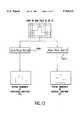
- FIG. 7is a block diagram of a second preferred embodiment of the motion-compensating de-interlacer of this invention.
- FIG. 8is a flow chart of a preferred control routine for the motion-compensating de-interlacer of this invention.
- FIG. 9illustrates the splitting of a composite single frame into an even field and an odd field
- FIG. 10is a flow chart of a preferred control routine for the motion map calculation step of FIG. 7;
- FIG. 11illustrates representative even and odd video frame fields and a corresponding motion map
- FIG. 12is a flow chart of a preferred control routine for the motion-compensated filtering step of FIG. 7;
- FIG. 13is a flow chart of a preferred control routine for calculating the spatial gradients of the even and odd fields
- FIG. 14is a flow chart of a preferred control routine for choosing a set of affine parameters used to compute global motion
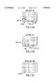
- FIG. 15illustrates a representative 8 ⁇ 8 block of image pixels
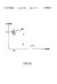
- FIG. 16illustrates the estimated affine parameters in two-dimensional space for 8 ⁇ 8 blocks of images pixels in the presence of both global and local motion
- FIG. 17Ashows a representative image field
- FIG. 17Bshows the representative image field of FIG. 17A after warping using the estimated affine parameters
- FIG. 18is a flow chart of a preferred control routine for the motion map calculation step of FIG. 10;
- FIG. 19is a flow chart of a preferred control routine for the motion-adaptive filtering step of FIG. 10;
- FIG. 20illustrates the merging of an even field and an odd field into a single frame
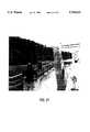
- FIG. 21is a motion-compensated progressive video frame having both global and local motion corresponding to FIG. 2, where the methods of this invention are used to compensate only for the global motion;
- FIG. 22is a motion-compensated video frame having both global and local motion corresponding to FIG. 2, where the methods of this invention are used to compensate for both the global motion and the local motion;
- FIG. 23is a motion-compensated progressive video frame having only local motion corresponding to FIG. 1, where the methods of this invention are used to compensate for the local motion.
- FIG. 5illustrates a video system 100 incorporating the motion-compensating de-interlacer 200 of this invention.
- the systemincludes an image processor 300 that receives video signals over signal line 310 from a video source 400.
- the image processor 300includes an image frame capture card (not shown) that captures and digitizes each video frame.
- the motion-compensating de-interlacer 200 of this inventionrequires only a single image frame as an input. Therefore, a conventional single-frame image capture card is preferably used in image processor 300. This reduces the cost and complexity of the video system 100.
- the image processor 300sends a digitized single video frame to the motion-compensating de-interlacer 200 over a signal line 320.
- the motion-compensating de-interlacer 200de-interlaces the video frame, compensates for global and local motion and outputs a motion-compensated progressive video frame over a signal line 330 to an output device or a storage device (not shown).
- the operation of the motion-compensating de-interlacerwill be explained in more detail below.
- FIG. 6illustrates a first preferred embodiment of the motion-compensating de-interlacer 200 of this invention.
- the motion-compensated de-interlacer 200includes a field splitter 500, a global motion determiner 510, a global motion compensator 520, a local motion determiner 530, a local motion interpolator 540 and a field combiner 550.
- the digitized single-frame of interlaced videois input to the field splitter 500 over the signal line 320.
- the field splittersplits the interlaced video frame into an even (E) field and an odd (O) field.
- the even and odd fieldsare output to the global motion determiner 510, the global motion compensator 520, the local motion determiner 530, the local motion interpolator 540 and the field combiner 550 over signal lines 502, 503, 504, 505 and 506, respectively.
- the global motion determiner 510outputs control signals over signal lines 511, 512 and 513 to the global motion compensator 520, the local motion determiner 530 and the field combiner 550, respectively.
- the global motion compensator 520outputs the globally-compensated video frame (E,O) G to the local motion determiner 530 and the local motion interpolator 540 over signal lines 521 and 522, respectively.
- the local motion determiner 530outputs control signals over signal lines 531 and 532 to the local motion interpolator 540 and the field combiner 550, respectively.
- the local motion compensator 540outputs either the globally compensated and locally-interpolated video frame (E,O) G ,L or the locally-interpolated video frame (E,O) L to the field combiner 550 over a signal line 541.
- the field combiner 550outputs a progressive video frame over the signal line 330.
- the field splitter 500splits an interlaced video frame into the even (E) and odd (O) fields and outputs the even and odd fields to the global motion determiner 510, the global motion compensator 520, the local motion determiner 530, the local motion interpolator 540 and the field combiner 550.
- the global motion determiner 510determines if global motion is present in the split video frame (E,O). If global motion is detected, the global motion determiner 510 directs the global motion compensator 520 to globally-compensate the even and odd fields, and output the globally-compensated split video frame (E,O) G to the local motion determiner 530, the local motion interpolator 540 and the field combiner 550. In addition, the global motion determiner 510 directs the local motion determiner 530 to determine if local motion is present in the globally-compensated split video frame (E,O) G . If the global motion determiner 510 does not detect global motion, it directs the local motion determiner 530 to determine if local motion is present in the split video frame (E,O).
- the local motion determiner 530determines if local motion is present in the globally-compensated split video frame (E,O) G output by the global motion compensator 520. If the local motion determiner 530 detects local motion, it directs the local motion interpolator 540 to locally interpolate the globally-compensated split video frame (E,O) G output from the global motion compensator 520. If global motion is not present in the split video frame (E,O), the local motion determiner 530 determines if local motion is present in the split video frame (E,O) output by the field splitter 500. If the local motion determiner 530 detects local motion, it directs the local motion interpolator 540 to locally interpolate the split video frame (E,O) output by the field splitter 500.
- the local motion interpolator 540outputs either a globally-compensated and locally-interpolated split video frame (E,O) G ,L or a locally-interpolated split video frame (E,O) L to the field combiner 550. However, if the local motion determiner 530 does not detect local motion in either the globally-compensated split video frame (E,O) G or the split video frame (E,O), the local motion interpolator 540 does not output either signal.
- the field combiner 550in response to control signals from the global motion determiner 510 and the local motion determiner 530, combines the even (E) and odd (O) fields of one of the split video frame (E,O), the globally-compensated split video frame (E,O) G , the globally-compensated and locally-interpolated split video frame (E,O) G ,L or the locally-interpolated split video frame (E,O) L into a progressive video frame.
- the field combiner 550outputs the progressive video frame over the signal line 330.
- FIG. 7illustrates a second preferred embodiment of the motion-compensating de-interlacer 200 of this invention.
- This embodimentcomprises a controller 600, a field splitter 610, a motion map calculator 620, a pixel counter 630, a motion-compensating filter 640, a motion-adaptive filter 650 and a field combiner 660.
- the controller 600outputs control signals over signal lines 601, 602, 603, 604 and 605 to the pixel counter 630, the motion map calculator 620, the motion-compensating filter 640, the motion-adaptive filter 650 and the field combiner 660, respectively.
- the digitized single-frame of interlaced videois input to the field splitter 610 over the signal line 320.
- the field splitter 610outputs the even (E) and odd (O) fields of the video frame to the motion map calculator 620, the motion-adaptive filter 650, the motion-compensating filter 640 and the field combiner 660 over signal lines 612, 613, 614 and 615, respectively.
- the motion map calculator 620outputs a motion map M to the pixel counter 630 and the motion-adaptive filter 650 over signal lines 621 and 622, respectively.
- the pixel counter 630outputs a pixel count PC to the controller 600 over a signal line 631.
- the motion-compensating filter 640 and the motion-adaptive filter 650each outputs a progressive video frame over a signal line 641 or a signal line 651, respectively.
- the field combiner 660outputs a progressive video frame over signal lines 661.
- the signal line 641, 651 and 661connect to the signal line 330.
- the field splitter 610splits the interlaced video frame into the even (E) and odd (O) fields.
- the field splitter 610outputs the even and odd fields E and O to the motion map calculator 620, the motion-compensating filter 640, the motion-adaptive filter 650 and the field combiner 660.
- the motion map calculator 620calculates a motion map M between the even and odd fields E and O and outputs the motion map M to the pixel counter 630 and the motion adaptive filter 650.
- the pixel counter 630counts the number of image pixels with a gray-level value of "0" (PC) and sends the result to the controller 600 over the signal line 631.
- the controller 600determines if there is global and/or local motion in the video frame based on the pixel count PC. If global motion is present, the controller 600 activates the motion-compensating filter 640.
- the motion-compensating filter 640compensates for the global motion and interpolates for any local motion that is present in the video frame.
- the motion-compensating filter 640also combines the motion-compensated even (E) and odd (O) fields of the compensated video frame into the compensated progressive video frame.
- the controller 600determines that there is local motion, but no global motion, in the video frame, the controller 600 activates the motion-adaptive filter 650.
- the motion-adaptive filter 650locally interpolates the video frame and combines the even (E) and odd (O) fields of the locally-interpolated video frame into a locally-interpolated progressive video frame.
- the controller 600determines that there is neither global nor local motion in the video frame, the controller 600 activates the field combiner 660, which combines the even (E) and odd (O) fields of the video frame into the progressive video frame.
- FIG. 8shows a preferred control routine for the motion-compensating de-interlacer 200 of this invention.
- the routinestarts at step S200 and proceeds to step S210, where it splits the digitized single video frame into an even field E and an odd field O, as illustrated in FIG. 9.
- the even and odd fields E and Oare subimages containing the even and odd lines of the video frame, respectively.
- step S220the control system calculates a motion map M1 using the threshold Th1 between the even and odd fields E and O by determining the field differences within a block around each image pixel. Control then continues to step S230.
- step S230the control system counts the number of pixels in the motion map M1 having a gray level value of 0 and assigns this number to the value PC.
- step S240the control system compares PC to a predetermined threshold value Th2. If PC is greater than Th2, the control system determines that there is global motion in the video frame. Control thus continues to step S250. Otherwise, is PC is less than or equal to Th2, the control system determines that there is no global motion in the video frame. Control thus jumps to step S260.
- the value Th2may be adjusted to calibrate the system. However, in the preferred embodiment, Th2 is set to P/2, where P is the total number of pixels in the video frame.
- step S250the control system estimates and compensates for the global motion present in the video frame. In addition, in step S250 the control system determines if local motion is present in the globally-compensated image. If local motion is detected, the pixels affected by the local motion are interpolated using motion-adaptive techniques. Control then jumps to step S290.
- step S260the control system determines if PC is greater than the threshold Th3.
- the threshold Th3is used to determine if local motion is present. Th3 may be adjusted to calibrate the system. However, Th3 is preferably set at a value below 0.10P, i.e. below approximately 10% of the total number of image pixels P in the video frame.
- step S270the routine locally interpolates the pixels affected by the local motion using edge-adaptive interpolation. Control then jumps to step S290.
- step S280the control system interleaves the fields E and O into a single interleaved progressive frame.
- the control systemthen continues to step S290.
- step S290the control routine stops.
- FIG. 10shows a preferred control routine for calculating a single image pixel of the motion map.
- the gray level, or intensity, of each image pixel in the motion mapis determined at step S222 by: ##EQU1## where: I e (i,j) and I o (i,j) are the gray levels of image pixel (i,j) in the even and odd fields, respectively; and
- the threshold Th1is the gray level threshold.
- the threshold Th1may be adjusted to calibrate the system, and is preferably between 0 and 50.
- control systemFor every image pixel in the video frame, the control system calculates the average gray level in a 1 ⁇ 3 pixel block centered on the image pixel being mapped. This average is calculated for both the even field E and the corresponding location in the odd field O. The control system then compares the average gray level in the corresponding even and odd field locations E and O. If the absolute value of the difference is greater than threshold Th1, control continues to step S224. Otherwise, control jumps to step S226.
- step S224a gray level of 0 (dark) is assigned to the motion map pixel M(i, j).
- a gray level of 255 (white)is assigned to motion map pixel M(i, j).
- FIG. 11shows a representative even field E, a representative odd field O and the corresponding motion map M1 calculated in step S220.
- the control systemcalculates the average gray level value for a 1 ⁇ 3 pixel block 700 centered on the image pixel (i,j) being mapped for both the even field and the corresponding location in the odd field.
- the control systemcompares the absolute value of the difference between the average gray level values in the corresponding E and O field locations to the predetermined threshold Th1 to determine which gray level value, 0 or 255, to assign to the motion map pixel (i,j).
- the difference in the average gray level value between the even and odd fields for the pixel (i,j)exceeds the threshold Th1. Therefore, the routine assigns a value of 0 to the motion map pixel (i,j).
- FIG. 12illustrates a preferred control routine for the motion-compensated filtering step S250.
- the control systemcalculates the spatial gradient for the even field E and for the odd field O, respectively, using the preferred control routine shown in FIG. 13.
- the control systemdetermines the global motion in step S254 using the spatial gradients H and V, and the even and odd fields E and O.
- the control systemcalculates affine parameter estimates (a 0 , a 1 , a 2 , a 3 , a 4 and a 5 ) using the well-known optical flow analysis and affine parametrization techniques discussed in Black et al., "The Robust Estimation of Multiple Motions: Parametric and Piecewise-Smooth Flow Fields," Computer Vision and Image Understanding, vol. 63, no. 1, January 1996, pp. 75-104.
- optical flow analysisis defined as:
- a 0 , a 1 , a 2 , a 3 , a 4 and a 5are the affine parameters
- H(i,j) and V(i,j)are the horizontal and vertical spatial gradients, respectively.
- I t (i,j)is the temporal difference between the even and odd fields.
- the control systemestimates the affine parameters using a least-squares estimation technique.
- Prior motion-compensating methodsuse all the image pixels within the E and O fields in the least-squares estimation of the affine parameters. However, this will result in a less accurate global motion estimation if local motion is also present.
- the control routine of FIG. 14is preferably used to determine the set of affine parameters used for estimating the global motion.
- step S256the control system compensates for the global motion by "warping" one of the fields using the affine parameter estimates a 0 , a 1 , a 2 , a 3 , a 4 and a 5 .
- every image pixel within the field being warpedis calculated using the optical flow estimates to obtain the motion-compensated field. If I or (i,j) is the gray-level of the pixel (i,j) in the original field (i.e., before warping), then the relationship between the motion-compensated field and the original field is:
- FIGS. 17A and 17Bshow a representative image field before and after warping.
- step S257the control system calculates a motion map between the warped odd field O w and the even field E. This is shown in greater detail in FIG. 18.
- step S258the control system motion-adaptively filters the fields E and O w . This is shown in greater detail in FIG. 19.
- FIG. 13shows steps S252 and S253 in greater detail.
- the spatial gradients in the horizontal direction H(i,j) for each image pixel location (i,j)are calculated at step S300 as:
- I(i,j)is the gray level for pixel location (i,j) for either the odd or even field.
- the control systemcalculates the spatial gradients in the vertical direction V(i,j) for both the even and odd fields at step S310 as:
- FIG. 14shows the method for determining the affine parameters in greater detailAs shown in FIG. 14, at step S400, the routine divides either the even field E or the odd field O field into 8 ⁇ 8 pixel blocks, as shown in the representative 8 ⁇ 8 pixel block shown in FIG. 15.
- step S410a set of affine parameters a i is estimated for each 8 ⁇ 8 pixel block using the least-squares estimation techniques described in Black et al.
- step S420the control system defines clusters of affine parameter sets a i .
- the control systembuilds the clusters by assigning any a i as a first cluster center a cl , and then defining (k-1) more cluster centers such that
- the threshold Th4determines the distance between the cluster centers, and may be adjusted to calibrate the system.
- step S430the control system assigns every affine parameter set a i to a cluster.
- the control systemassigns the affine parameter set a i by determining which cluster center a ck is closest to the affine parameter set a i .
- the control systemthen assigns that affine parameter set to that cluster.
- step S440the control system calculates new cluster centers a cknew such that: ##EQU2## where: a j is an affine parameter set that is assigned to new cluster k, and
- Wis the number of elements in the new cluster k.
- step S450the control system determines if any two cluster centers are too close to each other. If, for any two cluster centers a ci and a cj ,
- the threshold Th6defines the minimum distance between cluster centers, and may be adjusted to calibrate the system.
- step S460the control system merges the clusters i and j that are too close to each other and calculates a new cluster center a cnew as: ##EQU3## where: W 1 and W 2 are the number of elements in clasess i and j, respectively, and
- a jis a member of either cluster i or j. Control then continues to step S470.
- step S470the control system determines which cluster has the most elements. The control system then chooses the center of this cluster a cm as the affine parameter set to calculate the global motion estimates. Control then returns to step S256.
- FIG. 16is a graph of the estimated affine parameters, in two-dimensional space, for hypothetical 8 ⁇ 8 blocks of the image pixels in the presence of both global and local motion. Because the control system chooses the affine parameter set at the center of the cluster 900 with the most members, the effects of local motion on the affine parameter estimates are minimized, resulting in a more accurate global motion estimate.
- the control routine of FIG. 18operates in the same way as the control routine of FIG. 10, with the steps S500, S510 and S520 in FIG. 18 corresponding to steps S222, S224 and S226, respectively, in FIG. 10.
- the only differencesare the inputs in step S500, which are the gray levels of the E field I e (i,j) and the gray levels of the motion-compensated O field I w (i,j).
- the image pixels that have undergone local motionhave a gray-level value of "0".
- step S600the control system determines if any pixel has undergone local motion by analyzing the gray-level values in the motion map M2. If any local motion is present, control continues to step S610. Otherwise, if no local motion is present, control jumps to step S620.
- step S610the control system locally interpolates the pixels affected by the local motion using the well-known edge-adaptive interpolation techniques described in Wang et al.
- step S620the control system interleaves the E and O w fields into a single progressive frame, as shown in FIG. 20. Control then continues to step S259, which returns control to step S290.
- the motion-compensating de-interlacer 200 and the image processor 300are preferably implemented on programmed general purpose computers. However, they can also be implemented on a special purpose computer, a programmed microprocessor or microcontroller and peripheral integrated circuit elements, an ASIC or other integrated circuit, a hardwired electronic or logic circuit such as a discrete element circuit, a programmable logic device such as a PLD, PLA or PAL, or the like. In general, any device on which a finite state machine, capable of implementing the flowcharts shown in FIGS. 8, 10, 12, 13, 14, 18 and 19, can be implemented can be used to implement the motion-compensating de-interlacer 200 or 300 of this invention.
- FIG. 21shows a motion-compensated progressive video frame having both global and local motion corresponding to FIG. 2, where only the global motion is compensated for using this invention.
- FIG. 22shows a motion-compensated progressive video frame having both global and local motion corresponding to FIG. 2, where both the global motion and the local motion are compensated for using this invention.
- FIG. 23shows a motion-compensated progressive video frame having only local motion corresponding to FIG. 1, where the local motion is compensated for using this invention.
- the compensated video frames of FIGS. 21-23have higher resolution and exhibit a smaller "staircase" effect when compared to the corresponding video frames of FIGS. 1 and 2.
Landscapes
- Engineering & Computer Science (AREA)
- Multimedia (AREA)
- Signal Processing (AREA)
- Computer Graphics (AREA)
- Television Systems (AREA)
Abstract
Description
u(i,j)=a.sub.0 i+a.sub.1 j+a.sub.2 (2)
v(i,j)=a.sub.3 i+a.sub.4 j+a.sub.5 (3)
H(i,j)·u(i,j)+V(i,j)·v(i,j)+I.sub.t (i,j)=0(4)
I.sub.or (i,j)=I.sub.w (1+a.sub.0)i+a.sub.1 j+a.sub.2,a.sub.3 i+(1+a.sub.4)j+a.sub.5 ! (5)
H(i,j)=|I(i,j)-I(i+1,j)| (6)
V(i,j)=|I(i,j)-I(i,j+1)|. (7)
|a.sub.ci -a.sub.cj |>Th4 (8)
|a.sub.ci -a.sub.cj |<Th6 (10)
Claims (20)
Priority Applications (1)
| Application Number | Priority Date | Filing Date | Title |
|---|---|---|---|
| US08/775,215US5784115A (en) | 1996-12-31 | 1996-12-31 | System and method for motion compensated de-interlacing of video frames |
Applications Claiming Priority (1)
| Application Number | Priority Date | Filing Date | Title |
|---|---|---|---|
| US08/775,215US5784115A (en) | 1996-12-31 | 1996-12-31 | System and method for motion compensated de-interlacing of video frames |
Publications (1)
| Publication Number | Publication Date |
|---|---|
| US5784115Atrue US5784115A (en) | 1998-07-21 |
Family
ID=25103682
Family Applications (1)
| Application Number | Title | Priority Date | Filing Date |
|---|---|---|---|
| US08/775,215Expired - LifetimeUS5784115A (en) | 1996-12-31 | 1996-12-31 | System and method for motion compensated de-interlacing of video frames |
Country Status (1)
| Country | Link |
|---|---|
| US (1) | US5784115A (en) |
Cited By (75)
| Publication number | Priority date | Publication date | Assignee | Title |
|---|---|---|---|---|
| US6115502A (en)* | 1996-10-24 | 2000-09-05 | U.S. Philips Corporation | Noise filtering |
| US6122658A (en)* | 1997-07-03 | 2000-09-19 | Microsoft Corporation | Custom localized information in a networked server for display to an end user |
| US6122017A (en)* | 1998-01-22 | 2000-09-19 | Hewlett-Packard Company | Method for providing motion-compensated multi-field enhancement of still images from video |
| US6166772A (en)* | 1997-04-01 | 2000-12-26 | Compaq Computer Corporation | Method and apparatus for display of interlaced images on non-interlaced display |
| US6205178B1 (en)* | 1996-09-20 | 2001-03-20 | Hitachi, Ltd. | Method and synthesizing a predicted image, video coding device and video coding method |
| AU733040B2 (en)* | 1998-06-19 | 2001-05-03 | Canon Kabushiki Kaisha | A method of identifying image frames suitable for printing |
| US6252975B1 (en) | 1998-12-17 | 2001-06-26 | Xerox Corporation | Method and system for real time feature based motion analysis for key frame selection from a video |
| US6269484B1 (en)* | 1997-06-24 | 2001-07-31 | Ati Technologies | Method and apparatus for de-interlacing interlaced content using motion vectors in compressed video streams |
| US6304297B1 (en)* | 1998-07-21 | 2001-10-16 | Ati Technologies, Inc. | Method and apparatus for manipulating display of update rate |
| US6317459B1 (en) | 1997-03-14 | 2001-11-13 | Microsoft Corporation | Digital video signal encoder and encoding method |
| EP1024656A3 (en)* | 1999-01-29 | 2001-11-14 | Xerox Corporation | System for forming composite image |
| US20020036705A1 (en)* | 2000-06-13 | 2002-03-28 | Samsung Electronics Co., Ltd. | Format converter using bi-directional motion vector and method thereof |
| US20020136540A1 (en)* | 1997-10-06 | 2002-09-26 | Dvdo, Inc. | Digital video system and methods for providing same |
| US6459455B1 (en)* | 1999-08-31 | 2002-10-01 | Intel Corporation | Motion adaptive deinterlacing |
| US20020149703A1 (en)* | 2000-04-18 | 2002-10-17 | Adams Dale R. | Method, system and article of manufacture for identifying the source type and quality level of a video sequence |
| US20020163595A1 (en)* | 1999-08-11 | 2002-11-07 | Adams Dale R. | Interlace motion artifact detection using vertical frequency detection and analysis |
| US6489998B1 (en)* | 1998-08-11 | 2002-12-03 | Dvdo, Inc. | Method and apparatus for deinterlacing digital video images |
| US20020196362A1 (en)* | 2001-06-11 | 2002-12-26 | Samsung Electronics Co., Ltd. | Apparatus and method for adaptive motion compensated de-interlacing of video data |
| WO2001075798A3 (en)* | 2000-04-04 | 2003-01-16 | Smith & Nephew Inc | Method and system for automatic correction of motion artifacts |
| US6509930B1 (en)* | 1999-08-06 | 2003-01-21 | Hitachi, Ltd. | Circuit for scan conversion of picture signal using motion compensation |
| WO2003026284A1 (en)* | 2001-09-14 | 2003-03-27 | Sony Electronics, Inc. | Transformation of interlaced format into progressive format |
| US6552749B1 (en) | 1999-01-29 | 2003-04-22 | Intel Corporation | Method and apparatus for video motion compensation, reduction and color formatting |
| US6577345B1 (en)* | 1999-07-29 | 2003-06-10 | Lg Electronics Inc. | Deinterlacing method and apparatus based on motion-compensated interpolation and edge-directional interpolation |
| US6580812B1 (en)* | 1998-12-21 | 2003-06-17 | Xerox Corporation | Methods and systems for automatically adding motion lines representing motion to a still image |
| US20030122961A1 (en)* | 2001-12-28 | 2003-07-03 | Motorola, Inc. | Method for de-interlacing video information |
| US20030174776A1 (en)* | 1997-06-25 | 2003-09-18 | Nippon Telegraph And Telephone Corporation | Motion vector predictive encoding method, motion vector decoding method, predictive encoding apparatus and decoding apparatus, and storage media storing motion vector predictive encoding and decoding programs |
| US20030202591A1 (en)* | 2002-03-26 | 2003-10-30 | General Instrument Corporation | Methods and apparatus for efficient global motion compensation encoding and associated decoding |
| EP1377036A2 (en) | 2002-06-28 | 2004-01-02 | Microsoft Corporation | Video processing system and method for automatic enhancement of digital video |
| US20040036782A1 (en)* | 2002-08-20 | 2004-02-26 | Verna Knapp | Video image enhancement method and apparatus |
| US6734916B1 (en)* | 2000-10-04 | 2004-05-11 | Karl Sims | Video field artifact removal |
| US20040095999A1 (en)* | 2001-01-24 | 2004-05-20 | Erick Piehl | Method for compressing video information |
| US20040135926A1 (en)* | 2003-01-02 | 2004-07-15 | Samsung Electronics Co., Ltd. | Progressive scan method used in display using adaptive edge dependent interpolation |
| US20040174459A1 (en)* | 2002-08-30 | 2004-09-09 | Holt Gary R. | Video interlacing using object motion estimation |
| US20050053365A1 (en)* | 1997-10-06 | 2005-03-10 | Adams Dale R. | Portable DVD player |
| US20050062892A1 (en)* | 1998-07-23 | 2005-03-24 | Dvdo, Inc. | Method and apparatus for reducing on-chip memory in vertical video processing |
| US20050196052A1 (en)* | 2004-03-02 | 2005-09-08 | Jun Xin | System and method for joint de-interlacing and down-sampling using adaptive frame and field filtering |
| US20050243203A1 (en)* | 2004-05-03 | 2005-11-03 | Ati Technologies, Inc. | Apparatus and method for image rendering |
| US20050259950A1 (en)* | 2004-04-30 | 2005-11-24 | Thilo Landsiedel | Film mode correction in still areas |
| US20060061658A1 (en)* | 2002-12-13 | 2006-03-23 | Qinetiq Limited | Image stabilisation system and method |
| US7023487B1 (en) | 2002-01-25 | 2006-04-04 | Silicon Image, Inc. | Deinterlacing of video sources via image feature edge detection |
| US7064790B1 (en)* | 2001-05-14 | 2006-06-20 | Microsoft Corporation | Adaptive video data frame resampling |
| EP1694066A1 (en)* | 2005-02-18 | 2006-08-23 | Genesis Microchip, Inc. | Global motion adaptive deinterlacing system with motion values correction with respect to luminance level |
| US20060187344A1 (en)* | 2005-02-18 | 2006-08-24 | Genesis Microchip Inc. | Global motion adaptive system with motion values correction with respect to luminance level |
| US20060257042A1 (en)* | 2005-05-13 | 2006-11-16 | Microsoft Corporation | Video enhancement |
| US20070172211A1 (en)* | 2006-01-26 | 2007-07-26 | Prasanjit Panda | Adaptive filtering to enhance video bit-rate control performance |
| US20070211167A1 (en)* | 1998-10-05 | 2007-09-13 | Adams Dale R | Digital video system and methods for providing same |
| US20070258014A1 (en)* | 2006-05-02 | 2007-11-08 | Ati Technologies Inc. | Field sequence detector, method and video device |
| CN100385953C (en)* | 2001-07-10 | 2008-04-30 | 皇家菲利浦电子有限公司 | Unit and method for motion estimation and image processing apparatus equipped with such a motion estimation unit |
| US20080100730A1 (en)* | 2006-11-01 | 2008-05-01 | Canon Kabushiki Kaisha | Imaging apparatus and control method thereof |
| US20080246876A1 (en)* | 2007-04-04 | 2008-10-09 | Freescale Semiconductor, Inc. | Video de-interlacer using pixel trajectory |
| US20090087120A1 (en)* | 2007-09-28 | 2009-04-02 | Ati Technologies Ulc | Apparatus and method for generating a detail-enhanced upscaled image |
| US20090147133A1 (en)* | 2007-12-10 | 2009-06-11 | Ati Technologies Ulc | Method and apparatus for high quality video motion adaptive edge-directional deinterlacing |
| US20090161016A1 (en)* | 2007-12-21 | 2009-06-25 | Wong Daniel W | Run-Time Selection Of Video Algorithms |
| US20090167778A1 (en)* | 2007-12-28 | 2009-07-02 | Ati Technologies Ulc | Apparatus and method for single-pass, gradient-based motion compensated image rate conversion |
| US7589788B1 (en) | 2003-02-28 | 2009-09-15 | Intel Corporation | Method and apparatus for video motion compensation, reduction and color formatting |
| US20090268088A1 (en)* | 2008-04-25 | 2009-10-29 | Hui Zhou | Motion adaptive de-interlacer and method for use therewith |
| CN100574410C (en)* | 2004-02-27 | 2009-12-23 | Jbf合伙股份有限公司 | Image conversion method and device |
| US20100079667A1 (en)* | 2008-08-21 | 2010-04-01 | Vestel Elektronik Sanayi Ve Ticaret A.S. | Method and apparatus for increasing the frame rate of a video signal |
| US7903733B2 (en) | 2006-01-26 | 2011-03-08 | Qualcomm Incorporated | Adaptive filtering to enhance video encoder performance |
| US20120127267A1 (en)* | 2010-11-23 | 2012-05-24 | Qualcomm Incorporated | Depth estimation based on global motion |
| US8934055B1 (en)* | 2013-06-14 | 2015-01-13 | Pixelworks, Inc. | Clustering based motion layer detection |
| US8964117B2 (en) | 2007-09-28 | 2015-02-24 | Ati Technologies Ulc | Single-pass motion adaptive deinterlacer and method therefore |
| US9171372B2 (en) | 2010-11-23 | 2015-10-27 | Qualcomm Incorporated | Depth estimation based on global motion |
| US20180268519A1 (en)* | 2017-03-17 | 2018-09-20 | Magic Leap, Inc. | Mixed reality system with color virtual content warping and method of generating virtual content using same |
| CN108810601A (en)* | 2017-05-04 | 2018-11-13 | 福州瑞芯微电子股份有限公司 | Move subtitle de-interweaving method, system, mobile terminal and readable storage medium storing program for executing |
| US10812936B2 (en) | 2017-01-23 | 2020-10-20 | Magic Leap, Inc. | Localization determination for mixed reality systems |
| US10838207B2 (en) | 2015-03-05 | 2020-11-17 | Magic Leap, Inc. | Systems and methods for augmented reality |
| US10861130B2 (en) | 2017-03-17 | 2020-12-08 | Magic Leap, Inc. | Mixed reality system with virtual content warping and method of generating virtual content using same |
| US10861237B2 (en) | 2017-03-17 | 2020-12-08 | Magic Leap, Inc. | Mixed reality system with multi-source virtual content compositing and method of generating virtual content using same |
| US10909711B2 (en) | 2015-12-04 | 2021-02-02 | Magic Leap, Inc. | Relocalization systems and methods |
| US10943521B2 (en) | 2018-07-23 | 2021-03-09 | Magic Leap, Inc. | Intra-field sub code timing in field sequential displays |
| US11073699B2 (en) | 2016-08-02 | 2021-07-27 | Magic Leap, Inc. | Fixed-distance virtual and augmented reality systems and methods |
| US11379948B2 (en) | 2018-07-23 | 2022-07-05 | Magic Leap, Inc. | Mixed reality system with virtual content warping and method of generating virtual content using same |
| US11429183B2 (en) | 2015-03-05 | 2022-08-30 | Magic Leap, Inc. | Systems and methods for augmented reality |
| US20220286609A1 (en)* | 2015-12-16 | 2022-09-08 | Martineau & Associates | Method and apparatus for remanent imaging control |
Citations (4)
| Publication number | Priority date | Publication date | Assignee | Title |
|---|---|---|---|---|
| US5016102A (en)* | 1989-04-27 | 1991-05-14 | Sony Corporation | Motion dependent video signal processing |
| US5510834A (en)* | 1992-04-13 | 1996-04-23 | Dv Sweden Ab | Method for adaptive estimation of unwanted global picture instabilities in picture sequences in digital video signals |
| US5579054A (en)* | 1995-04-21 | 1996-11-26 | Eastman Kodak Company | System and method for creating high-quality stills from interlaced video |
| US5682205A (en)* | 1994-08-19 | 1997-10-28 | Eastman Kodak Company | Adaptive, global-motion compensated deinterlacing of sequential video fields with post processing |
- 1996
- 1996-12-31USUS08/775,215patent/US5784115A/ennot_activeExpired - Lifetime
Patent Citations (4)
| Publication number | Priority date | Publication date | Assignee | Title |
|---|---|---|---|---|
| US5016102A (en)* | 1989-04-27 | 1991-05-14 | Sony Corporation | Motion dependent video signal processing |
| US5510834A (en)* | 1992-04-13 | 1996-04-23 | Dv Sweden Ab | Method for adaptive estimation of unwanted global picture instabilities in picture sequences in digital video signals |
| US5682205A (en)* | 1994-08-19 | 1997-10-28 | Eastman Kodak Company | Adaptive, global-motion compensated deinterlacing of sequential video fields with post processing |
| US5579054A (en)* | 1995-04-21 | 1996-11-26 | Eastman Kodak Company | System and method for creating high-quality stills from interlaced video |
Non-Patent Citations (14)
| Title |
|---|
| Computer Vision and Image Understanding, vol. 63, No. 1, Jan. 1996, "The Robust Estimation of Multiple Motions: Parametric and Piecewise-Smooth Flow Fields", Michael J. Black et al., pp. 75-104. |
| Computer Vision and Image Understanding, vol. 63, No. 1, Jan. 1996, The Robust Estimation of Multiple Motions: Parametric and Piecewise Smooth Flow Fields , Michael J. Black et al., pp. 75 104.* |
| IEEE ICASSP, May 1989, "Spatial Interpolation of Interlaced Television Pictures", Dennis M. Martinez et al., pp. 1886-1889. |
| IEEE ICASSP, May 1989, Spatial Interpolation of Interlaced Television Pictures , Dennis M. Martinez et al., pp. 1886 1889.* |
| IEEE ICASSP, May 1991, "Motion/Pattern Adaptive Interpolation of Interlaced Video Sequences", Yao Wang et al., pp. 2829-2832. |
| IEEE ICASSP, May 1991, Motion/Pattern Adaptive Interpolation of Interlaced Video Sequences , Yao Wang et al., pp. 2829 2832.* |
| IEEE Transactions on Pattern Analysis and Machine Intelligence, vol. 15, No. 4, Apr. 1993, Image Representation Using Block Pattern Models and its Image Processing Applications, Yao Wang et al., pp. 321 335.* |
| IEEE Transactions on Pattern Analysis and Machine Intelligence, vol. 15, No. 4, Apr. 1993, Image Representation Using Block Pattern Models and its Image Processing Applications, Yao Wang et al., pp. 321-335. |
| Panasonic AG EP80 Video Printer (NTSC), product brochure.* |
| Panasonic AG-EP80 Video Printer (NTSC), product brochure. |
| Prentice Hall, 1995, "Digital Video Processing", a. Murat Tekalp, pp. 322-323. |
| Prentice Hall, 1995, Digital Video Processing , a. Murat Tekalp, pp. 322 323.* |
| Signal Processing: Image Communication, vol. 5, 1993, "Block Motion Compensated Coding of Interlaced Sequences Using Adaptively Deinterlaced Fields", Andre Zaccarin et al., pp. 473-485. |
| Signal Processing: Image Communication, vol. 5, 1993, Block Motion Compensated Coding of Interlaced Sequences Using Adaptively Deinterlaced Fields , Andre Zaccarin et al., pp. 473 485.* |
Cited By (153)
| Publication number | Priority date | Publication date | Assignee | Title |
|---|---|---|---|---|
| US6205178B1 (en)* | 1996-09-20 | 2001-03-20 | Hitachi, Ltd. | Method and synthesizing a predicted image, video coding device and video coding method |
| US6115502A (en)* | 1996-10-24 | 2000-09-05 | U.S. Philips Corporation | Noise filtering |
| US20050220188A1 (en)* | 1997-03-14 | 2005-10-06 | Microsoft Corporation | Digital video signal encoder and encoding method |
| US7154951B2 (en) | 1997-03-14 | 2006-12-26 | Microsoft Corporation | Motion video signal encoder and encoding method |
| US20040184533A1 (en)* | 1997-03-14 | 2004-09-23 | Microsoft Corporation | Motion video signal encoder and encoding method |
| US20040184534A1 (en)* | 1997-03-14 | 2004-09-23 | Microsoft Corporation | Motion video signal encoder and encoding method |
| US6707852B1 (en) | 1997-03-14 | 2004-03-16 | Microsoft Corporation | Digital video signal encoder and encoding method |
| US7139313B2 (en) | 1997-03-14 | 2006-11-21 | Microsoft Corporation | Digital video signal encoder and encoding method |
| US7072396B2 (en) | 1997-03-14 | 2006-07-04 | Microsoft Corporation | Motion video signal encoder and encoding method |
| US6317459B1 (en) | 1997-03-14 | 2001-11-13 | Microsoft Corporation | Digital video signal encoder and encoding method |
| US6937657B2 (en) | 1997-03-14 | 2005-08-30 | Microsoft Corporation | Motion video signal encoder and encoding method |
| US20040184535A1 (en)* | 1997-03-14 | 2004-09-23 | Microsoft Corporation | Motion video signal encoder and encoding method |
| US6504577B1 (en) | 1997-04-01 | 2003-01-07 | Compaq Information Technologies Group, L.P. | Method and apparatus for display of interlaced images on non-interlaced display |
| US6166772A (en)* | 1997-04-01 | 2000-12-26 | Compaq Computer Corporation | Method and apparatus for display of interlaced images on non-interlaced display |
| US6269484B1 (en)* | 1997-06-24 | 2001-07-31 | Ati Technologies | Method and apparatus for de-interlacing interlaced content using motion vectors in compressed video streams |
| US20070183505A1 (en)* | 1997-06-25 | 2007-08-09 | Nippon Telegraph And Telephone Corporation | Motion vector predictive encoding method, motion vector decoding method, predictive encoding apparatus and decoding apparatus, and storage media storing motion vector predictive encoding and decoding programs |
| US9154789B2 (en) | 1997-06-25 | 2015-10-06 | Nippon Telegraph And Telephone Corporation | Motion vector predictive encoding and decoding method using prediction of motion vector of target block based on representative motion vector |
| US20030174776A1 (en)* | 1997-06-25 | 2003-09-18 | Nippon Telegraph And Telephone Corporation | Motion vector predictive encoding method, motion vector decoding method, predictive encoding apparatus and decoding apparatus, and storage media storing motion vector predictive encoding and decoding programs |
| US7206346B2 (en) | 1997-06-25 | 2007-04-17 | Nippon Telegraph And Telephone Corporation | Motion vector predictive encoding method, motion vector decoding method, predictive encoding apparatus and decoding apparatus, and storage media storing motion vector predictive encoding and decoding programs |
| US6122658A (en)* | 1997-07-03 | 2000-09-19 | Microsoft Corporation | Custom localized information in a networked server for display to an end user |
| US7215376B2 (en) | 1997-10-06 | 2007-05-08 | Silicon Image, Inc. | Digital video system and methods for providing same |
| US20020136540A1 (en)* | 1997-10-06 | 2002-09-26 | Dvdo, Inc. | Digital video system and methods for providing same |
| US7359624B2 (en) | 1997-10-06 | 2008-04-15 | Silicon Image, Inc. | Portable DVD player |
| US20050053365A1 (en)* | 1997-10-06 | 2005-03-10 | Adams Dale R. | Portable DVD player |
| US6122017A (en)* | 1998-01-22 | 2000-09-19 | Hewlett-Packard Company | Method for providing motion-compensated multi-field enhancement of still images from video |
| AU733040B2 (en)* | 1998-06-19 | 2001-05-03 | Canon Kabushiki Kaisha | A method of identifying image frames suitable for printing |
| US6304297B1 (en)* | 1998-07-21 | 2001-10-16 | Ati Technologies, Inc. | Method and apparatus for manipulating display of update rate |
| US20050062892A1 (en)* | 1998-07-23 | 2005-03-24 | Dvdo, Inc. | Method and apparatus for reducing on-chip memory in vertical video processing |
| US7027099B2 (en)* | 1998-08-11 | 2006-04-11 | Silicon Image | Method and apparatus for deinterlacing digital video images |
| US6489998B1 (en)* | 1998-08-11 | 2002-12-03 | Dvdo, Inc. | Method and apparatus for deinterlacing digital video images |
| US20040056978A1 (en)* | 1998-08-11 | 2004-03-25 | Dvdo, Inc. | Method and apparatus for deinterlacing digital video images |
| US7499103B2 (en) | 1998-08-11 | 2009-03-03 | Silicon Image, Inc. | Method and apparatus for detecting frequency in digital video images |
| US20070211167A1 (en)* | 1998-10-05 | 2007-09-13 | Adams Dale R | Digital video system and methods for providing same |
| US6252975B1 (en) | 1998-12-17 | 2001-06-26 | Xerox Corporation | Method and system for real time feature based motion analysis for key frame selection from a video |
| US6580812B1 (en)* | 1998-12-21 | 2003-06-17 | Xerox Corporation | Methods and systems for automatically adding motion lines representing motion to a still image |
| EP1024656A3 (en)* | 1999-01-29 | 2001-11-14 | Xerox Corporation | System for forming composite image |
| US6594403B1 (en) | 1999-01-29 | 2003-07-15 | Xerox Corporation | Systems and methods for registering scanned documents |
| US6552749B1 (en) | 1999-01-29 | 2003-04-22 | Intel Corporation | Method and apparatus for video motion compensation, reduction and color formatting |
| US6577345B1 (en)* | 1999-07-29 | 2003-06-10 | Lg Electronics Inc. | Deinterlacing method and apparatus based on motion-compensated interpolation and edge-directional interpolation |
| US6509930B1 (en)* | 1999-08-06 | 2003-01-21 | Hitachi, Ltd. | Circuit for scan conversion of picture signal using motion compensation |
| US20020163595A1 (en)* | 1999-08-11 | 2002-11-07 | Adams Dale R. | Interlace motion artifact detection using vertical frequency detection and analysis |
| US7633559B2 (en)* | 1999-08-11 | 2009-12-15 | Silicon Image, Inc. | Interlace motion artifact detection using vertical frequency detection and analysis |
| US6909469B2 (en) | 1999-08-11 | 2005-06-21 | Silicon Image, Inc. | Interlace motion artifact detection using vertical frequency detection and analysis |
| US7391481B2 (en) | 1999-08-11 | 2008-06-24 | Silicon Image, Inc. | Interlace motion artifact detection using vertical frequency detection and analysis |
| US20080122974A1 (en)* | 1999-08-11 | 2008-05-29 | Adams Dale R | Interlace Motion Artifact Detection Using Vertical Frequency Detection And Analysis |
| US20050162563A1 (en)* | 1999-08-11 | 2005-07-28 | Adams Dale R. | Interlace motion artifact detection using vertical frequency detection and analysis |
| US6459455B1 (en)* | 1999-08-31 | 2002-10-01 | Intel Corporation | Motion adaptive deinterlacing |
| JP2015167397A (en)* | 2000-04-04 | 2015-09-24 | スミス アンド ネフュー インコーポレーテッド | Method and system for automatic correction of motion artifact |
| US6842196B1 (en) | 2000-04-04 | 2005-01-11 | Smith & Nephew, Inc. | Method and system for automatic correction of motion artifacts |
| AU2001245731B2 (en)* | 2000-04-04 | 2006-08-24 | Smith & Nephew, Inc. | Method and system for automatic correction of motion artifacts |
| JP2014017839A (en)* | 2000-04-04 | 2014-01-30 | Smith & Nephew Inc | Method and system for automatic correction of motion artifact |
| WO2001075798A3 (en)* | 2000-04-04 | 2003-01-16 | Smith & Nephew Inc | Method and system for automatic correction of motion artifacts |
| US6867814B2 (en) | 2000-04-18 | 2005-03-15 | Silicon Image, Inc. | Method, system and article of manufacture for identifying the source type and quality level of a video sequence |
| US20020149703A1 (en)* | 2000-04-18 | 2002-10-17 | Adams Dale R. | Method, system and article of manufacture for identifying the source type and quality level of a video sequence |
| US20020036705A1 (en)* | 2000-06-13 | 2002-03-28 | Samsung Electronics Co., Ltd. | Format converter using bi-directional motion vector and method thereof |
| US6900846B2 (en)* | 2000-06-13 | 2005-05-31 | Samsung Electronics Co., Ltd. | Format converter using bi-directional motion vector and method thereof |
| US6734916B1 (en)* | 2000-10-04 | 2004-05-11 | Karl Sims | Video field artifact removal |
| US20040095999A1 (en)* | 2001-01-24 | 2004-05-20 | Erick Piehl | Method for compressing video information |
| US7894525B2 (en)* | 2001-01-24 | 2011-02-22 | Oy Gamecluster Ltd. | Method for compressing video information |
| US7064790B1 (en)* | 2001-05-14 | 2006-06-20 | Microsoft Corporation | Adaptive video data frame resampling |
| US7042512B2 (en)* | 2001-06-11 | 2006-05-09 | Samsung Electronics Co., Ltd. | Apparatus and method for adaptive motion compensated de-interlacing of video data |
| US20020196362A1 (en)* | 2001-06-11 | 2002-12-26 | Samsung Electronics Co., Ltd. | Apparatus and method for adaptive motion compensated de-interlacing of video data |
| CN100385953C (en)* | 2001-07-10 | 2008-04-30 | 皇家菲利浦电子有限公司 | Unit and method for motion estimation and image processing apparatus equipped with such a motion estimation unit |
| GB2396510A (en)* | 2001-09-14 | 2004-06-23 | Sony Electronics Inc | Transformation of interlaced format into progressive format |
| US6847405B2 (en) | 2001-09-14 | 2005-01-25 | Sony Corporation | Motion-adaptive de-interlacing method and system for digital televisions |
| GB2396510B (en)* | 2001-09-14 | 2005-04-06 | Sony Electronics Inc | Transformation of interlaced format into progressive format |
| WO2003026284A1 (en)* | 2001-09-14 | 2003-03-27 | Sony Electronics, Inc. | Transformation of interlaced format into progressive format |
| US20030122961A1 (en)* | 2001-12-28 | 2003-07-03 | Motorola, Inc. | Method for de-interlacing video information |
| US7023487B1 (en) | 2002-01-25 | 2006-04-04 | Silicon Image, Inc. | Deinterlacing of video sources via image feature edge detection |
| US7602848B2 (en)* | 2002-03-26 | 2009-10-13 | General Instrument Corporation | Methods and apparatus for efficient global motion compensation encoding and associated decoding |
| US20030202591A1 (en)* | 2002-03-26 | 2003-10-30 | General Instrument Corporation | Methods and apparatus for efficient global motion compensation encoding and associated decoding |
| EP1377036B1 (en)* | 2002-06-28 | 2011-04-27 | Microsoft Corporation | Video processing system and method for automatic enhancement of digital video |
| EP1377036A2 (en) | 2002-06-28 | 2004-01-02 | Microsoft Corporation | Video processing system and method for automatic enhancement of digital video |
| US20040036782A1 (en)* | 2002-08-20 | 2004-02-26 | Verna Knapp | Video image enhancement method and apparatus |
| US8384790B2 (en)* | 2002-08-20 | 2013-02-26 | Hewlett-Packard Development Company, L.P. | Video image enhancement method and apparatus using reference and auxiliary frames |
| US7362374B2 (en) | 2002-08-30 | 2008-04-22 | Altera Corporation | Video interlacing using object motion estimation |
| US20040174459A1 (en)* | 2002-08-30 | 2004-09-09 | Holt Gary R. | Video interlacing using object motion estimation |
| US20060061658A1 (en)* | 2002-12-13 | 2006-03-23 | Qinetiq Limited | Image stabilisation system and method |
| US7609293B2 (en)* | 2002-12-13 | 2009-10-27 | Qinetiq Limited | Image stabilisation system and method |
| US20040135926A1 (en)* | 2003-01-02 | 2004-07-15 | Samsung Electronics Co., Ltd. | Progressive scan method used in display using adaptive edge dependent interpolation |
| US7126643B2 (en)* | 2003-01-02 | 2006-10-24 | Samsung Electronics Co., Ltd. | Progressive scan method used in display using adaptive edge dependent interpolation |
| US7589788B1 (en) | 2003-02-28 | 2009-09-15 | Intel Corporation | Method and apparatus for video motion compensation, reduction and color formatting |
| US7652721B1 (en)* | 2003-08-22 | 2010-01-26 | Altera Corporation | Video interlacing using object motion estimation |
| CN100574410C (en)* | 2004-02-27 | 2009-12-23 | Jbf合伙股份有限公司 | Image conversion method and device |
| US7483577B2 (en) | 2004-03-02 | 2009-01-27 | Mitsubishi Electric Research Laboratories, Inc. | System and method for joint de-interlacing and down-sampling using adaptive frame and field filtering |
| US20050196052A1 (en)* | 2004-03-02 | 2005-09-08 | Jun Xin | System and method for joint de-interlacing and down-sampling using adaptive frame and field filtering |
| US20050259950A1 (en)* | 2004-04-30 | 2005-11-24 | Thilo Landsiedel | Film mode correction in still areas |
| US20050243203A1 (en)* | 2004-05-03 | 2005-11-03 | Ati Technologies, Inc. | Apparatus and method for image rendering |
| US7633549B2 (en) | 2004-05-03 | 2009-12-15 | Ati Technologies, Inc. | Apparatus and method for image rendering |
| EP1596595A1 (en)* | 2004-05-03 | 2005-11-16 | ATI Technologies Inc. | Apparatus and method for image rendering |
| US20060187344A1 (en)* | 2005-02-18 | 2006-08-24 | Genesis Microchip Inc. | Global motion adaptive system with motion values correction with respect to luminance level |
| US7471336B2 (en)* | 2005-02-18 | 2008-12-30 | Genesis Microchip Inc. | Global motion adaptive system with motion values correction with respect to luminance level |
| EP1694066A1 (en)* | 2005-02-18 | 2006-08-23 | Genesis Microchip, Inc. | Global motion adaptive deinterlacing system with motion values correction with respect to luminance level |
| US20060187345A1 (en)* | 2005-02-18 | 2006-08-24 | Genesis Microchip Inc. | Global motion adaptive system with motion values correction with respect to luminance level |
| US7675573B2 (en)* | 2005-02-18 | 2010-03-09 | Genesis Microchip Inc. | Global motion adaptive system with motion values correction with respect to luminance level |
| US7548659B2 (en)* | 2005-05-13 | 2009-06-16 | Microsoft Corporation | Video enhancement |
| US20060257042A1 (en)* | 2005-05-13 | 2006-11-16 | Microsoft Corporation | Video enhancement |
| US7903733B2 (en) | 2006-01-26 | 2011-03-08 | Qualcomm Incorporated | Adaptive filtering to enhance video encoder performance |
| US8009963B2 (en)* | 2006-01-26 | 2011-08-30 | Qualcomm Incorporated | Adaptive filtering to enhance video bit-rate control performance |
| US20070172211A1 (en)* | 2006-01-26 | 2007-07-26 | Prasanjit Panda | Adaptive filtering to enhance video bit-rate control performance |
| US8682100B2 (en) | 2006-05-02 | 2014-03-25 | Ati Technologies Ulc | Field sequence detector, method and video device |
| US7953293B2 (en)* | 2006-05-02 | 2011-05-31 | Ati Technologies Ulc | Field sequence detector, method and video device |
| US20110211074A1 (en)* | 2006-05-02 | 2011-09-01 | Ati Technologies Ulc | Field sequence detector, method and video device |
| US20070258014A1 (en)* | 2006-05-02 | 2007-11-08 | Ati Technologies Inc. | Field sequence detector, method and video device |
| US20080100730A1 (en)* | 2006-11-01 | 2008-05-01 | Canon Kabushiki Kaisha | Imaging apparatus and control method thereof |
| US20080246876A1 (en)* | 2007-04-04 | 2008-10-09 | Freescale Semiconductor, Inc. | Video de-interlacer using pixel trajectory |
| US8115863B2 (en) | 2007-04-04 | 2012-02-14 | Freescale Semiconductor, Inc. | Video de-interlacer using pixel trajectory |
| US8300987B2 (en) | 2007-09-28 | 2012-10-30 | Ati Technologies Ulc | Apparatus and method for generating a detail-enhanced upscaled image |
| US8964117B2 (en) | 2007-09-28 | 2015-02-24 | Ati Technologies Ulc | Single-pass motion adaptive deinterlacer and method therefore |
| US20090087120A1 (en)* | 2007-09-28 | 2009-04-02 | Ati Technologies Ulc | Apparatus and method for generating a detail-enhanced upscaled image |
| US8259228B2 (en) | 2007-12-10 | 2012-09-04 | Ati Technologies Ulc | Method and apparatus for high quality video motion adaptive edge-directional deinterlacing |
| US20090147133A1 (en)* | 2007-12-10 | 2009-06-11 | Ati Technologies Ulc | Method and apparatus for high quality video motion adaptive edge-directional deinterlacing |
| US20090161016A1 (en)* | 2007-12-21 | 2009-06-25 | Wong Daniel W | Run-Time Selection Of Video Algorithms |
| US8396129B2 (en) | 2007-12-28 | 2013-03-12 | Ati Technologies Ulc | Apparatus and method for single-pass, gradient-based motion compensated image rate conversion |
| US20090167778A1 (en)* | 2007-12-28 | 2009-07-02 | Ati Technologies Ulc | Apparatus and method for single-pass, gradient-based motion compensated image rate conversion |
| US20090268088A1 (en)* | 2008-04-25 | 2009-10-29 | Hui Zhou | Motion adaptive de-interlacer and method for use therewith |
| US20100079667A1 (en)* | 2008-08-21 | 2010-04-01 | Vestel Elektronik Sanayi Ve Ticaret A.S. | Method and apparatus for increasing the frame rate of a video signal |
| US8194184B2 (en)* | 2008-08-21 | 2012-06-05 | Vestel Elektronik Sanayi Ve Ticaret A.S. | Method and apparatus for increasing the frame rate of a video signal |
| US20120127267A1 (en)* | 2010-11-23 | 2012-05-24 | Qualcomm Incorporated | Depth estimation based on global motion |
| US9123115B2 (en)* | 2010-11-23 | 2015-09-01 | Qualcomm Incorporated | Depth estimation based on global motion and optical flow |
| US9171372B2 (en) | 2010-11-23 | 2015-10-27 | Qualcomm Incorporated | Depth estimation based on global motion |
| US8934055B1 (en)* | 2013-06-14 | 2015-01-13 | Pixelworks, Inc. | Clustering based motion layer detection |
| US11619988B2 (en) | 2015-03-05 | 2023-04-04 | Magic Leap, Inc. | Systems and methods for augmented reality |
| US11429183B2 (en) | 2015-03-05 | 2022-08-30 | Magic Leap, Inc. | Systems and methods for augmented reality |
| US11256090B2 (en) | 2015-03-05 | 2022-02-22 | Magic Leap, Inc. | Systems and methods for augmented reality |
| US10838207B2 (en) | 2015-03-05 | 2020-11-17 | Magic Leap, Inc. | Systems and methods for augmented reality |
| US12386417B2 (en) | 2015-03-05 | 2025-08-12 | Magic Leap, Inc. | Systems and methods for augmented reality |
| US11288832B2 (en) | 2015-12-04 | 2022-03-29 | Magic Leap, Inc. | Relocalization systems and methods |
| US10909711B2 (en) | 2015-12-04 | 2021-02-02 | Magic Leap, Inc. | Relocalization systems and methods |
| US20220286609A1 (en)* | 2015-12-16 | 2022-09-08 | Martineau & Associates | Method and apparatus for remanent imaging control |
| US12333942B2 (en) | 2015-12-16 | 2025-06-17 | Martineau & Associates | Method and apparatus for remanent imaging control |
| US11862021B2 (en)* | 2015-12-16 | 2024-01-02 | Martineau & Associates | Method and apparatus for remanent imaging control |
| US11536973B2 (en) | 2016-08-02 | 2022-12-27 | Magic Leap, Inc. | Fixed-distance virtual and augmented reality systems and methods |
| US11073699B2 (en) | 2016-08-02 | 2021-07-27 | Magic Leap, Inc. | Fixed-distance virtual and augmented reality systems and methods |
| US11711668B2 (en) | 2017-01-23 | 2023-07-25 | Magic Leap, Inc. | Localization determination for mixed reality systems |
| US11206507B2 (en) | 2017-01-23 | 2021-12-21 | Magic Leap, Inc. | Localization determination for mixed reality systems |
| US10812936B2 (en) | 2017-01-23 | 2020-10-20 | Magic Leap, Inc. | Localization determination for mixed reality systems |
| US10861130B2 (en) | 2017-03-17 | 2020-12-08 | Magic Leap, Inc. | Mixed reality system with virtual content warping and method of generating virtual content using same |
| US10762598B2 (en)* | 2017-03-17 | 2020-09-01 | Magic Leap, Inc. | Mixed reality system with color virtual content warping and method of generating virtual content using same |
| US11410269B2 (en) | 2017-03-17 | 2022-08-09 | Magic Leap, Inc. | Mixed reality system with virtual content warping and method of generating virtual content using same |
| US11423626B2 (en) | 2017-03-17 | 2022-08-23 | Magic Leap, Inc. | Mixed reality system with multi-source virtual content compositing and method of generating virtual content using same |
| US11315214B2 (en)* | 2017-03-17 | 2022-04-26 | Magic Leap, Inc. | Mixed reality system with color virtual content warping and method of generating virtual con tent using same |
| US10964119B2 (en) | 2017-03-17 | 2021-03-30 | Magic Leap, Inc. | Mixed reality system with multi-source virtual content compositing and method of generating virtual content using same |
| US20180268519A1 (en)* | 2017-03-17 | 2018-09-20 | Magic Leap, Inc. | Mixed reality system with color virtual content warping and method of generating virtual content using same |
| US10861237B2 (en) | 2017-03-17 | 2020-12-08 | Magic Leap, Inc. | Mixed reality system with multi-source virtual content compositing and method of generating virtual content using same |
| US11978175B2 (en) | 2017-03-17 | 2024-05-07 | Magic Leap, Inc. | Mixed reality system with color virtual content warping and method of generating virtual content using same |
| CN108810601A (en)* | 2017-05-04 | 2018-11-13 | 福州瑞芯微电子股份有限公司 | Move subtitle de-interweaving method, system, mobile terminal and readable storage medium storing program for executing |
| CN108810601B (en)* | 2017-05-04 | 2020-10-27 | 福州瑞芯微电子股份有限公司 | Motion subtitle de-interleaving method, system, mobile terminal and readable storage medium |
| US10943521B2 (en) | 2018-07-23 | 2021-03-09 | Magic Leap, Inc. | Intra-field sub code timing in field sequential displays |
| US11790482B2 (en) | 2018-07-23 | 2023-10-17 | Magic Leap, Inc. | Mixed reality system with virtual content warping and method of generating virtual content using same |
| US12190468B2 (en) | 2018-07-23 | 2025-01-07 | Magic Leap, Inc. | Mixed reality system with virtual content warping and method of generating virtual content using same |
| US11379948B2 (en) | 2018-07-23 | 2022-07-05 | Magic Leap, Inc. | Mixed reality system with virtual content warping and method of generating virtual content using same |
| US11501680B2 (en) | 2018-07-23 | 2022-11-15 | Magic Leap, Inc. | Intra-field sub code timing in field sequential displays |
Similar Documents
| Publication | Publication Date | Title |
|---|---|---|
| US5784115A (en) | System and method for motion compensated de-interlacing of video frames | |
| US6262773B1 (en) | System for conversion of interlaced video to progressive video using edge correlation | |
| KR0183149B1 (en) | Motion image detection method | |
| EP1223748B1 (en) | Motion detection in an interlaced video signal | |
| US7265791B2 (en) | Method and apparatus for de-interlacing video signal | |
| US6118488A (en) | Method and apparatus for adaptive edge-based scan line interpolation using 1-D pixel array motion detection | |
| EP0757482B1 (en) | An edge-based interlaced to progressive video conversion system | |
| US5661525A (en) | Method and apparatus for converting an interlaced video frame sequence into a progressively-scanned sequence | |
| EP0677958B1 (en) | Motion adaptive scan conversion using directional edge interpolation | |
| EP1164792A2 (en) | Format converter using bidirectional motion vector and method thereof | |
| US6141056A (en) | System for conversion of interlaced video to progressive video using horizontal displacement | |
| US8189105B2 (en) | Systems and methods of motion and edge adaptive processing including motion compensation features | |
| US20050249282A1 (en) | Film-mode detection in video sequences | |
| JPH1188893A (en) | Image signal processing device | |
| JP2005318621A (en) | Ticker processing in video sequences | |
| WO2008152951A1 (en) | Method of and apparatus for frame rate conversion | |
| US8345148B2 (en) | Method and system for inverse telecine and scene change detection of progressive video | |
| KR100422575B1 (en) | An Efficient Spatial and Temporal Interpolation system for De-interlacing and its method | |
| US20070103589A1 (en) | Image signal processing apparatus, image signal processing method and program | |
| US7499102B2 (en) | Image processing apparatus using judder-map and method thereof | |
| JP3189292B2 (en) | Scan line interpolator | |
| JP4179089B2 (en) | Motion estimation method for motion image interpolation and motion estimation device for motion image interpolation | |
| JP2004320279A (en) | Dynamic image time axis interpolation method and dynamic image time axis interpolation apparatus | |
| JP3121519B2 (en) | Motion interpolation method and motion interpolation circuit using motion vector, and motion vector detection method and motion vector detection circuit | |
| JP2770300B2 (en) | Image signal processing |
Legal Events
| Date | Code | Title | Description |
|---|---|---|---|
| AS | Assignment | Owner name:XEROX CORPORATION, CONNECTICUT Free format text:ASSIGNMENT OF ASSIGNORS INTEREST;ASSIGNOR:BOZDAGI, GOZDE;REEL/FRAME:008391/0191 Effective date:19961226 | |
| STCF | Information on status: patent grant | Free format text:PATENTED CASE | |
| FPAY | Fee payment | Year of fee payment:4 | |
| AS | Assignment | Owner name:BANK ONE, NA, AS ADMINISTRATIVE AGENT, ILLINOIS Free format text:SECURITY INTEREST;ASSIGNOR:XEROX CORPORATION;REEL/FRAME:013153/0001 Effective date:20020621 | |
| AS | Assignment | Owner name:JPMORGAN CHASE BANK, AS COLLATERAL AGENT, TEXAS Free format text:SECURITY AGREEMENT;ASSIGNOR:XEROX CORPORATION;REEL/FRAME:015134/0476 Effective date:20030625 Owner name:JPMORGAN CHASE BANK, AS COLLATERAL AGENT,TEXAS Free format text:SECURITY AGREEMENT;ASSIGNOR:XEROX CORPORATION;REEL/FRAME:015134/0476 Effective date:20030625 | |
| FPAY | Fee payment | Year of fee payment:8 | |
| FPAY | Fee payment | Year of fee payment:12 | |
| AS | Assignment | Owner name:XEROX CORPORATION, CONNECTICUT Free format text:RELEASE BY SECURED PARTY;ASSIGNOR:JPMORGAN CHASE BANK, N.A. AS SUCCESSOR-IN-INTEREST ADMINISTRATIVE AGENT AND COLLATERAL AGENT TO JPMORGAN CHASE BANK;REEL/FRAME:066728/0193 Effective date:20220822 |