US5783811A - Portable data collection device with LED targeting and illumination assembly - Google Patents
Portable data collection device with LED targeting and illumination assemblyDownload PDFInfo
- Publication number
- US5783811A US5783811AUS08/606,619US60661996AUS5783811AUS 5783811 AUS5783811 AUS 5783811AUS 60661996 AUS60661996 AUS 60661996AUS 5783811 AUS5783811 AUS 5783811A
- Authority
- US
- United States
- Prior art keywords
- illumination
- target area
- assembly
- dataform
- image
- Prior art date
- Legal status (The legal status is an assumption and is not a legal conclusion. Google has not performed a legal analysis and makes no representation as to the accuracy of the status listed.)
- Expired - Lifetime
Links
Images


Classifications
- G—PHYSICS
- G06—COMPUTING OR CALCULATING; COUNTING
- G06K—GRAPHICAL DATA READING; PRESENTATION OF DATA; RECORD CARRIERS; HANDLING RECORD CARRIERS
- G06K7/00—Methods or arrangements for sensing record carriers, e.g. for reading patterns
- G06K7/10—Methods or arrangements for sensing record carriers, e.g. for reading patterns by electromagnetic radiation, e.g. optical sensing; by corpuscular radiation
- G06K7/10544—Methods or arrangements for sensing record carriers, e.g. for reading patterns by electromagnetic radiation, e.g. optical sensing; by corpuscular radiation by scanning of the records by radiation in the optical part of the electromagnetic spectrum
- G06K7/10712—Fixed beam scanning
- G06K7/10722—Photodetector array or CCD scanning
- G06K7/10752—Exposure time control
- G—PHYSICS
- G01—MEASURING; TESTING
- G01J—MEASUREMENT OF INTENSITY, VELOCITY, SPECTRAL CONTENT, POLARISATION, PHASE OR PULSE CHARACTERISTICS OF INFRARED, VISIBLE OR ULTRAVIOLET LIGHT; COLORIMETRY; RADIATION PYROMETRY
- G01J3/00—Spectrometry; Spectrophotometry; Monochromators; Measuring colours
- G01J3/46—Measurement of colour; Colour measuring devices, e.g. colorimeters
- G01J3/50—Measurement of colour; Colour measuring devices, e.g. colorimeters using electric radiation detectors
- G01J3/51—Measurement of colour; Colour measuring devices, e.g. colorimeters using electric radiation detectors using colour filters
- G01J3/513—Measurement of colour; Colour measuring devices, e.g. colorimeters using electric radiation detectors using colour filters having fixed filter-detector pairs
- G—PHYSICS
- G06—COMPUTING OR CALCULATING; COUNTING
- G06K—GRAPHICAL DATA READING; PRESENTATION OF DATA; RECORD CARRIERS; HANDLING RECORD CARRIERS
- G06K7/00—Methods or arrangements for sensing record carriers, e.g. for reading patterns
- G06K7/10—Methods or arrangements for sensing record carriers, e.g. for reading patterns by electromagnetic radiation, e.g. optical sensing; by corpuscular radiation
- G06K7/10544—Methods or arrangements for sensing record carriers, e.g. for reading patterns by electromagnetic radiation, e.g. optical sensing; by corpuscular radiation by scanning of the records by radiation in the optical part of the electromagnetic spectrum
- G06K7/10554—Moving beam scanning
- G06K7/10564—Light sources
- G—PHYSICS
- G06—COMPUTING OR CALCULATING; COUNTING
- G06K—GRAPHICAL DATA READING; PRESENTATION OF DATA; RECORD CARRIERS; HANDLING RECORD CARRIERS
- G06K7/00—Methods or arrangements for sensing record carriers, e.g. for reading patterns
- G06K7/10—Methods or arrangements for sensing record carriers, e.g. for reading patterns by electromagnetic radiation, e.g. optical sensing; by corpuscular radiation
- G06K7/10544—Methods or arrangements for sensing record carriers, e.g. for reading patterns by electromagnetic radiation, e.g. optical sensing; by corpuscular radiation by scanning of the records by radiation in the optical part of the electromagnetic spectrum
- G06K7/10712—Fixed beam scanning
- G06K7/10722—Photodetector array or CCD scanning
- G06K7/10732—Light sources
- G—PHYSICS
- G06—COMPUTING OR CALCULATING; COUNTING
- G06K—GRAPHICAL DATA READING; PRESENTATION OF DATA; RECORD CARRIERS; HANDLING RECORD CARRIERS
- G06K7/00—Methods or arrangements for sensing record carriers, e.g. for reading patterns
- G06K7/10—Methods or arrangements for sensing record carriers, e.g. for reading patterns by electromagnetic radiation, e.g. optical sensing; by corpuscular radiation
- G06K7/10544—Methods or arrangements for sensing record carriers, e.g. for reading patterns by electromagnetic radiation, e.g. optical sensing; by corpuscular radiation by scanning of the records by radiation in the optical part of the electromagnetic spectrum
- G06K7/10792—Special measures in relation to the object to be scanned
- G—PHYSICS
- G01—MEASURING; TESTING
- G01J—MEASUREMENT OF INTENSITY, VELOCITY, SPECTRAL CONTENT, POLARISATION, PHASE OR PULSE CHARACTERISTICS OF INFRARED, VISIBLE OR ULTRAVIOLET LIGHT; COLORIMETRY; RADIATION PYROMETRY
- G01J3/00—Spectrometry; Spectrophotometry; Monochromators; Measuring colours
- G01J3/02—Details
- G01J3/0272—Handheld
- G—PHYSICS
- G01—MEASURING; TESTING
- G01J—MEASUREMENT OF INTENSITY, VELOCITY, SPECTRAL CONTENT, POLARISATION, PHASE OR PULSE CHARACTERISTICS OF INFRARED, VISIBLE OR ULTRAVIOLET LIGHT; COLORIMETRY; RADIATION PYROMETRY
- G01J3/00—Spectrometry; Spectrophotometry; Monochromators; Measuring colours
- G01J3/02—Details
- G01J3/10—Arrangements of light sources specially adapted for spectrometry or colorimetry
- G—PHYSICS
- G01—MEASURING; TESTING
- G01J—MEASUREMENT OF INTENSITY, VELOCITY, SPECTRAL CONTENT, POLARISATION, PHASE OR PULSE CHARACTERISTICS OF INFRARED, VISIBLE OR ULTRAVIOLET LIGHT; COLORIMETRY; RADIATION PYROMETRY
- G01J3/00—Spectrometry; Spectrophotometry; Monochromators; Measuring colours
- G01J3/28—Investigating the spectrum
- G01J3/2803—Investigating the spectrum using photoelectric array detector
- G—PHYSICS
- G06—COMPUTING OR CALCULATING; COUNTING
- G06K—GRAPHICAL DATA READING; PRESENTATION OF DATA; RECORD CARRIERS; HANDLING RECORD CARRIERS
- G06K2207/00—Other aspects
- G06K2207/1011—Aiming
Definitions
- the present inventionrelates to a portable data collection device including a two dimensional color photosensor array imaging assembly and, more particularly, to a portable data collection device having a two dimensional color photosensor array imaging assembly selectively actuatable to read a bar code dataform and record an image of an item of interest.
- Portable data collection devicesare widely used in manufacturing, service and package delivery industries to perform a variety of on-site data collection activities. Such portable data collection devices often include integrated bar code dataform readers adapted to read bar code dataforms affixed to products, product packaging and/or containers in warehouses, retail stores, shipping terminals, etc. for inventory control, tracking, production control and expediting, quality assurance and other purposes.
- Various bar code dataform readershave been proposed for portable data collection devices including laser scanners and one dimensional (1D) charge coupled device (CCD) imaging assemblies, both of which are capable of reading 1D bar code dataforms, that is, bar codes consisting of a single row of contrasting black bars and white spaces of varying widths. Both of these readers are also capable of reading a "stacked" two dimensional (2D) bar code dataforms such as PDF417, which has row indicator patterns utilized by the reader for vertical synchronization.
- 1Dcharge coupled device
- a two dimensional (2D) imaging based dataform readerhas been proposed in U.S. application Ser. No. 08/544,618, filed Oct. 18, 1995 and entitled "Extended Working Range Dataform Reader Including Fuzzy Logic Image Control Circuitry".
- the 2D dataform reader disclosed in application Ser. No. 08/544,618which is assigned to the assignee of the present application, includes an imaging assembly having a two dimensional array of photosensor (also referred throughout as photodiodes or pixels) adapted to read 2D bar code dataforms (e.g., PDF417, Supercode, etc.) with vertical synchronization row indicator patterns as well as matrix dataforms (e.g., MaxiCode, Data Matrix, Code 1, etc.) which do not include vertical synchronization patterns.
- the 2D dataform reader disclosed in application Ser. No. 08/544,618utilizes an open loop feedback control system including fuzzy logic circuitry to determine proper exposure time and gain parameters for a camera assembly.
- a portable data collection devicehaving a 2D imaging assembly that can be actuated to read bar code dataforms by depressing a trigger and, when a problem item is found, the imaging assembly can be actuated with a separate trigger to record an image of the problem item.
- the delivery personupon delivery of a package, the delivery person typically uses a portable data collection device to read a bar code dataform affixed to the delivered package. Normally, the delivery person also obtains a signature of the person receiving the package. Typically, the signature of the person receiving the package is on a sheet of paper that must be filed with the package delivery records or on a signature capture digitizer pad so that the signature may electronically filed.
- a portable collection data devicehaving a 2D imaging assembly that can be actuated to read a bar code dataform by depressing one trigger and can be actuated by a separate trigger, or applications software, to record an image of a signature of a person receiving a package so that the signature can be filed electronically.
- a single triggercould be used to decode a dataform and capture an image of the recipient's signature
- the dataformcould be encoded if the signature block is at a predetermined position with respect to the dataform
- a signal imagemay include both the dataform and the signature block.
- Typical "color photosensor arrays”include a red, green and blue (RGB) microfilter overlying a traditional 2D photosensor array to provide for color image data.
- RGBred, green and blue
- a typical color filter for a 2D photosensor arraycomprises a matrix of positions overlying corresponding a pixel positions. Typically, 50% of the positions are green, 25% of the positions are red and the remaining 25% of the positions are blue.
- the color of a filter positioneffects the transmittivity of light through that position and, therefore, the intensity of illumination incident on a photosensor or pixel overlied by the filter position.
- the charge accumulating on a given photosensor over an exposure periodis dependent on the intensity of illumination incident on that photosensor.
- An imaging assemblyutilizing a charge coupled device to read out charges accumulated on photosensors accumulated over an exposure period convert the charges accumulated on individual photosensors to an analog voltage signal and an A/D converter converts the signal into digital gray scale values representing a frame of a captured image and stores the gray scale values in a frame buffer memory.
- the gray scale values of the pixels within the frameare analyzed by the imaging system to identify a dataform pattern, which is subsequently decoded by decoding circuitry of the imaging assembly.
- a color filterdifferentially alters the illumination intensity incident on a photosensor depending on whether the photosensor is overlied by a red, green or blue filter position, the resulting gray scale value would also be altered. Accordingly, the addition of a color filter to a photosensor array would decrease an imaging system's ability to accurately identify and decode a dataform imaged in a captured frame image, that is, imaging in color would decrease the effective resolution of the imaging assembly, i.e., the assembly's ability to read of a dataform in a captured image frame.
- What is needis portable data collection device including a color imaging system with a color filter wherein the imaging system includes compensation circuitry to compensate for the variation in light transmittivity of different colored filter positions so that a dataform in a captured image may be accurately identified and decoded by the imaging system.
- a portable data collection deviceincludes a two dimensional (2D) photosensor array color imaging assembly selectively actuatable for reading bar code dataforms (bar code dataform reading mode) and recording an image of an item in the imaging assembly's target area or field (imaging mode).
- the portable data collection deviceincludes two trigger switches, a first trigger actuatable for reading a bar code dataform and a second trigger actuatable for recording an image of an item in the target area.
- a radio moduleis provided for transmitting an output signal to a remote device.
- an output signalis coupled to a terminal processing board for further processing and storage.
- the imaging assembly of the portable data collection device of the present inventionfurther includes control and selection circuitry which receives input signals from a user of the portable data collection device and determines and formats an appropriate output signal.
- the output signalmay include data from a decoded dataform imaged in a captured image frame, a compressed representation of a captured color image, an uncompressed representation of a captured color image, or a combination of these. If the desired output signal is decoded dataform data, the selection circuitry may utilize compensation circuitry to adjust the gray scale value of each pixel in a captured image frame to emulate the image that would have been captured by a black and white photosensor array.
- the selection circuitrybypasses the compensation circuitry and stores a digital representation of the captured color image in the buffer memory, then, if appropriate, invokes a compression module to compress the image to reduce the quantity of data to be transmitted by a radio module of the portable data collection device to a remote device or to be output to a terminal processing board of the portable data collection device.
- the portable data collection device of the present inventionincludes two manually activated trigger switches for controlling the selection circuitry to select between a color imaging capture mode and a dataform decoding mode.
- a first trigger switch, the dataform decoding triggerinstitutes the dataform decoding mode and signals the selection circuitry to output a decoded representation of a dataform in a captured image frame.
- the second trigger switch, the imaging triggerinstitutes the imaging mode and has two operating embodiments. In the first operating embodiment of the imaging mode, depressing the imaging trigger results in the imaging assembly capturing one frame of the field of view or target area of the camera assembly. In the second operating embodiment of the imaging mode, depressing the imaging trigger results in the imaging assembly continuously capturing successive frames as long as the trigger is depressed.
- activation of the dataform reading triggerwill result in both decoded data and at least a portion of the captured image frame being output.
- This embodimentwould advantageously be employed in a situation where a dataform is associated with, for example, a signature block in proximity to the dataform wherein the dataform includes encoded data setting forth the position of the signature block with respect to some predetermined location on the dataform.
- the dataform decoding triggeris actuated, an image of the dataform and associated signature block is captured.
- the dataformis decoded and the decoded data is analyzed by the selection circuitry to determine the location of the signature block.
- the output signalincludes both the decoded data and an image of the signature block.
- the portable data collection device of the present inventionincludes an voice capture module which captures and digitizes sound received through a microphone mounted on the device during actuation of the second trigger. This feature enables an operator to "attach" a verbal message to the captured image.
- the digitized signal representing the captured sound portionis processed by a voice compression module prior to output to the radio module or the terminal processing board.
- the imaging assemblyincludes a camera assembly having a photosensor array assembly including a two dimensional (2D) array of photosensors or pixels overlied by a color RGB (red, green and blue) filter and a control and decoder board.
- the control and decoder boardincludes high resolution black and white compensation circuitry, decoding circuitry, image compression circuitry, control and selection circuitry, serial output circuitry and exposure parameter control circuitry and image buffering circuitry including signal processing circuitry, a frame buffer memory and memory scanner/synchronization generator circuitry.
- the signal processing circuitryincludes synchronization extractor circuitry and an analog to digital (A/D) converter for converting a composite video signal generated by the camera assembly to a digital signal.
- the decoding circuitryincludes a decoder for decoding 1D and 2D bar code dataforms.
- the exposure parameter control circuitryincludes fuzzy logic control circuitry for controlling the frame exposure period and gain adjustment of the camera assembly.
- the imaging assemblyfurther includes an illumination assembly for illuminating a target item in the imaging assembly target area and an optic assembly for focusing reflected light from the target area upon the 2D array of photosensors of the photosensor array assembly.
- the optic assemblyincludes a plurality of lens positioned to the front of the 2D photosensor array for focusing reflected light from the target area onto the photosensor array.
- a shroudsupports the optic assembly and shrouds ambient illumination from the photosensor array.
- the camera assemblyincludes the 2D photosensor array, exposure period control circuitry and gain control circuitry mounted on a printed circuit board.
- the illumination assemblyincludes an array of LED illuminators for uniformly illuminating the target area and two targeting LED illuminators for generating a cross hair illumination intensity pattern for aiming the portable data collection device appropriately.
- the devicein a first housing embodiment of the portable data collection device of the present invention, includes pistol-grip shaped housing enclosing circuitry of the device.
- An angled snout extending from a grip portion of the housingincludes an opening through which a portion of the illuminator module and optics assembly extends.
- a finger operated triggeris provided on a target facing surface of the housing. The trigger is depressed by an operator to actuate the imaging assembly to read a bar code dataform in the target area.
- a push button actuatorextends through an opening of the housing spaced apart from the trigger. The push button actuator is located so as to be depressible by the operator's thumb as the housing is cradled in the operator's hand. Depressing the push button actuator actuates the imaging assembly to capture an image of the target area.
- a thin rectangular shaped housingsupports a workslate computer.
- the workslate computerincludes an interactive display screen and a keypad supported by a top surface of the housing.
- the housingdefines an interior region which encloses circuitry of the device.
- a side surface of the housingincludes an opening through which a portion of the illumination assembly and optic assembly extend.
- Two push button actuatorsare provided on opposite sides of the display screen. One actuator actuates the imaging assembly to read a bar code dataform in the target area, while the other actuator actuates the imaging assembly to capture an image of the target area.
- FIG. 1is a perspective view of a first embodiment of a portable data collection device of the present invention
- FIG. 2is a top view of the portable data collection device of FIG. 1;
- FIG. 3is a front elevation view of the portable data collection device of FIG. 1 as seen from a plane indicated by the line 3--3 in FIG. 2;
- FIG. 4is a sectional view of the portable data collection device of FIG. 1 as seen from a plane indicated by the line 4--4 in FIG. 3;
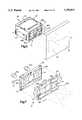
- FIG. 5is a perspective view of a modular portion of an imaging assembly of the portable data collection device of the present invention, the modular portion shown imaging a target dataform on an item;
- FIG. 6is a view of the modular portion of the imaging assembly of FIG. 5 with an upper half of the housing removed;
- FIG. 7is an exploded perspective view of an illumination assembly of the modular portion of the imaging assembly of FIG. 5;
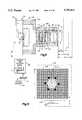
- FIG. 8is a sectional view of the front panel of the illumination assembly of FIG. 7 as seen from a plane indicated by the line 8--8 in FIG. 7;
- FIG. 9is a sectional view of the front panel of the illumination assembly of FIG. 7 as seen from a plane indicated by the line 9--9 in FIG. 7;
- FIG. 10is a sectional view of the front panel of the illumination assembly of FIG. 7 as seen from a plane indicated by the line 10--10 in FIG. 7;
- FIG. 11is a sectional view of an optic assembly of the modular portion of the imaging assembly of FIG. 5;
- FIG. 12is a representation of a matrix dataform and an associated signature block
- FIG. 13Ais one portion of a block diagram of selected circuitry of the portable data collection device of the present invention.
- FIG. 13Bis a second portion of a block diagram of selected circuitry of the portable data collection device of the present invention, the second portion matching the first portion shown in FIG. 13A;
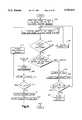
- FIG. 14is a flow chart setting forth one operating embodiment of the portable data collection device of the present invention to decode a bar code dataform and capture an image of a target area;
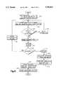
- FIG. 15is a flow chart setting forth a second operating embodiment of the portable data collection device of the present invention to decode a bar code dataform and capture an image of a target area;
- FIG. 16is a flowchart setting forth a third operating embodiment of the portable data collection device of the present invention wherein a captured image frame includes a dataform and a signature block as shown in FIG. 12 and in which decoded dataform data and a portion of the capture image are output;
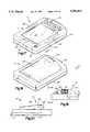
- FIG. 17is a perspective view of a top side of a second embodiment of a portable data collection device of the present invention.
- FIG. 18is another perspective view of a bottom side of the portable data collection device of FIG. 17;
- FIG. 19is a side elevation view of the right side of the portable data collection device of FIG. 17 as seen from a plane indicated by the line 19--19 in FIG. 18;
- FIG. 20is a side elevation view of the left side of the portable data collection device of FIG. 17 as seen from a plane indicated by the line 20--20 in FIG. 19.
- the data collection device 10includes a housing 12 defining an interior region.
- the housing 12includes a gripping portion 14 sized to be grasped in the hand of an operator and an angled snout 16 extending from the gripping portion.
- the snout 16includes an opening through which a portion of a two dimensional (2D) photosensor array imaging assembly 18 extends.
- the imaging assembly 18includes a modular portion 20 and a control and decoder board 22 electrically coupled to the electronic circuitry in the modular portion.
- the control and decoder board 22is supported within the gripping portion 14 of the housing 12.
- a power source 24such as a rechargeable battery for supplying operating power to the portable data collection device 10.
- a dataform reading trigger switch or actuator 26extends through an opening in the gripping portion 14. Also extending through an opening in the gripping portion 14 is an imaging push button trigger switch or actuator 28.
- the dataform reading trigger 26is positioned to be depressed by an index finger of the operator while the gripping portion 14 of the housing 12 is held in the operator's hand.
- the imaging trigger 28is positioned to be depressed by a thumb of an operator while the gripping portion 14 of the housing 12 is held in the operator's hand.
- the gripping portion 14also includes two small openings through which a distal portion of a red light emitting diode (LED) indicator 30 and a distal portion of a green LED indicator 32 extend.
- the housing 12includes an opening exposing a portion of a microphone 34 mounted in the housing interior region and another opening through which a radio antenna 36 extends. The interior region of the housing 12 supports the imaging assembly 18 and other electronic circuitry to be described below.
- the module portionincludes a housing 40 which supports an illumination assembly 42 and a camera assembly 38.
- the housing 40includes an upper portion 39a and a lower portion 39b which advantageously are the same part positioned symmetrically about a part line 41.
- the camera assembly 38includes an optic assembly 43 which focuses an image of a target area 44 onto a photosensor array assembly 48 (discussed later).
- the illumination assembly 42includes four illumination optic portion 88a, 88b, 88c, 88d each of which projects an even intensity distribution of illumination across the target area 44.
- FIG. 6is a top view of the modular portion 20 with the upper portion 39a of the housing 40 removed.
- the camera assembly 38includes a rear printed circuit board 52 and a front printed circuit board 54, both of which are secured in the housing 40 in slots 56a, 56b, 56c, 56d.
- a two dimensional color photosensor array assembly 48including a 2D sensor array 49 with an overlying RGB filter 50 is positioned on the front surface of the front printed circuit board 54 and receives reflected illumination from the target area 44 focused through optic assembly 43.
- a shroud 58(FIG. 11) positions the optic assembly 43 with respect to photodetector array assembly 48 and shrouds ambient illumination from the photodetector array assembly 48.
- the illumination assembly 42includes a printed circuit board 60, a lens array 62 and two targeting LEDs 64a, 64b.
- a plurality of exposure LEDs 66are disposed on the front surface of printed circuit board 60 to direct illumination through the lens array 62 towards the target area 44.
- circuit board 60 and the lens array 62are secured in slots 56e, 56f, 56g, 56h in the upper and lower housing portion 39a, 39b. Securing the camera assembly 38 and the illumination assembly in the same housing 40 assures that illumination is properly directed into the target area 44.
- FIG. 11shows a cross section of the camera assembly 38 with optic assembly 43 focusing an image of the target area 44 onto photosensor array assembly 48.
- the performance of the portable data collection device 10is enhanced by the optic assembly 43 which provides the camera assembly 38 with an extended working range.
- the optic assembly 43Based on the distance between the optic assembly 43 and the photosensor array assembly 48, there exists a best focus position S2 in front of the forward most surface 90 of the optic assembly 43 at which an image of an object in the target area 44 will be focused sharpest on the photosensor array 49.
- the image sharpnessgradually degrades as the object is moved towards a near field cut off distance S1 and a far field cut off distance S3.
- the optic assembly 43has an angular field of view 47 which is wide enough to image large dataforms at the far field S3 and still provide a large image of a small dataform at the near field S1.
- the portable data collection device 10has a working range from about 2.5 inches to at least 8.5 inches from a front surface 90 of the optic assembly 43 with the best focus distance S2 being about 5.5 inches (approximately 140 mm) from the front surface 90.
- the preferred field of viewcorresponds to a target area or surface 5 inches long by 3.75 inches high at a distance of 8.5 inches from the front surface 90.
- the preferred optic assembly 43includes 5 lenses and a metal disk 98 having a pin hole aperture 98a which, as shown, includes eleven optical surfaces labeled 90-110.
- the rear most optic surface 110is positioned 10.2 mm to the front of the photosensor array 49.
- the best focus positionis at 140 mm to the front of the front optic surface 90.
- the optic prescriptions for each of the optic surfacesare as follows
- the distance between successive optical surfaces 90-110is as follows:
- Such an optic assemblyis available from Marshall Electronics, Inc. of Culver City, Calif.
- the illumination assembly 42must provide adequate illumination of the target area 44 during the exposure period so that enough reflected light is absorbed by the photosensor array 49 to generate a suitably bright image.
- the exposure periodis normally limited to 0.01 seconds or less to minimize the smear effect of an operator's hand jittering during the dataform reading session. Therefore, the illumination assembly 42 must provide adequate illumination to accommodate the large F# and short exposure time.
- the minimum required object field illumination for this inventionis 106 lux at the far field cut off distance S3.
- the assemblyincludes a first and second targeting LEDs 64a, 64b.
- a printed circuit board assembly 60which include a plurality of exposure illumination LEDs 66 and a polycarbonate lens array 62.
- the printed circuit board assembly 60includes printed conductors and a power lead 112 operative for supplying power to the illumination LEDs 66.
- a suitable surface mount illumination LEDis produced by the MarkTech Corporation of Latham, N.Y., as Part No. MTSM735K-UR or MTSM745KA-UR.
- Each illumination LED 66provides illuminosity of 285 milli candela (mcd) over an angular illumination field of about 68 degrees.
- each illumination LED 66enables four LEDs to be placed in a row measuring less than 14 mm.
- the printed circuit board assembly 60includes four banks of four illumination LEDs 66 totalling sixteen illumination LEDs providing 4560 mcd of uniform illumination over the field of view 44.
- the lens array 62includes four illumination optic portions 88a, 88b, 88c, 88d each of which are aligned with a corresponding bank of illumination LEDs 66.
- the illumination optic portions 88a, 88b, 88c, 88ddirect a 68 degree illumination from each illumination LED 66 into a uniform field having an angular field of view which substantially corresponds to the angular field of view of the optics assembly 17 which defines the target area 44 (shown in FIG. 5).
- each optic portionincludes four vertically oriented cylindrical entry surfaces 116, one positioned in front of each LED 66 and a horizontally oriented exit surface positioned in front of each bank of LEDs 66.
- the vertically oriented cylindrical surfaces 116define the horizontal field of illumination and the horizontally oriented cylinders 118 define the vertical field of illumination. This arrangement provides an even illumination intensity distribution across the target area 44.
- the 4560 mcd of illumination provided by the illumination LEDs 60will provide an illumination intensity in excess of 106 lux at the far field cut off distance of 8.5 inches.
- the targeting illuminators 64a, 64bwhen energized, project illumination through apertures 68, 70 in the printed circuit board 60 and into first and second targeting optics 72, 74 respectively of the lens array 62.
- the targeting illuminators 64a, 64bare typical LED assemblies molded in an acrylic optic.
- the first targeting optics 72 shown in cross section in FIG. 9includes an aspherical entry surface 76 and a horizontally positioned cylindrical exit surface 78.
- the aspherical entry surfacehas a radius of 4.97 mm and a conic constant of -8.8549.
- the cylindrical exit surfacehas a radius of 10 mm and is tipped at an angle "a" equal to 6.170 degrees from center.
- aspherical entry surface 76 and cylindrical exit surface 78 of the first targeting optics 72interact to generate an illumination intensity distribution that appears to be a thin horizontal line 80 with a narrow height and a width approximately equal to the width of the target area 44.
- the tip angle "a"shifts the horizontal position of the line such that it is horizontally centered in the target area 44.
- the second targeting optics 74again shown in cross section in FIG. 9, includes an aspherical entry surface 84 and a vertically oriented cylindrical exit surface 86.
- the aspherical entry surface 84has a radius of 4.5537 mm and a conic constant of -5.6710.
- the cylindrical exit surface 86has a radius of 12.5 mm and is tipped at an angle "b" equal to 6.17 degrees from the center. Referring to FIG. 7 again, these surfaces interact to form an illumination intensity distribution that appears to be a thin vertical line 82 with a narrow width and a height approximately equal to the height of the target area 44.
- the combination of horizontal line 80 and vertical line 82form a cross hair illumination intensity pattern to assist the operator in aiming the portable data collection device 10.
- the photosensor array assembly 48is a PAL (phase alteration line) interlaced 752 by 582 pixel matrix charge coupled device (CCD) which, when read out generate s an interlaced video signal 250 (FIG. 13).
- This embodiment of the photosensor array assembly 48will be referred to as the interlaced CCD embodiment of the photosensor array.
- the photosensor array assembly 48could include a progressive scan CCD, a frame transfer CCD or an array of photodiodes and read out circuitry produced in accordance with U.S. Pat. No. 5,262,861 to Wilder which includes read out circuitry capable of independently and selectively reading out individual or group of pixels.
- the camera assembly 38When the imaging assembly 18 is actuated, the camera assembly 38 produces successive frames of an image of the target area 44.
- the framesare composed of interlaced fields generated from reading out charges accumulated during an exposure period on the individual photosensors comprising the photosensor array 49.
- a clock generator 256provides clocking signals to the photosensor array assembly 48 to read out pixels and generate an interlaced video signal 250.
- the video signal 250is amplified and filtered by gain control circuitry 252 of the camera assembly 38 resulting in a gain adjusted video signal 253.
- Synchronization signalsare generated by synchronization signal circuitry 258 to indicate which portions of the video signal 250 correspond to which photosensors or pixels of the photosensor array assembly 48.
- the synchronization signalsalong with standard black level signals are incorporated into the gain adjusted video signal 253 by analog signal processing circuitry 260 generating the PAL composite analog video signal 262 which is output to signal processing circuitry 264 on the control and decoder board 22. It should be appreciated that selection of another photosensor array will be similarly read out to generate a composite video signal.
- the formatmay be NTSC (National Television System Committee) standard if the selected array is NTSC or a noninterlaced format if a frame transfer or progressive scan CCD array is chosen.
- a read out of photosensors in the photosensor array assembly 48generates a field of an image data representative of illumination incident on the array.
- Two interlaced fieldsi.e., two read outs of the photosensor array assembly 48
- the camera assembly 38generates consecutive fields of the image incident on the photosensor array assembly 48.
- the analog video signal 262is input to the signal processing circuitry 264 along with clocking signals 68 from the camera assembly clock generator 256 and synchronization signals 270 from the camera assembly synchronization signal circuitry 258.
- the signal processing circuitry 264includes synchronization extractor circuitry which receives the clocking signals 268 and the synchronization signals 270 and generates signals which are coupled to an analog to digital converter (A/D converter) 272 causing the A/D converter to periodically digitize the composite analog video signal 262.
- A/D converter 272generates a series of 8 bit gray scale values, one gray scale value for each pixels of the photosensor array 48.
- the periodicity of the A/D converter 272is based on a non-continuous clock generated by the signal processing circuitry 264 and a portion of the signal corresponding to one frame is captured or stored in a color frame buffer memory 274.
- a gray scale value for a photosensor or pixelis proportional to a voltage magnitude of the portion of the analog video signal 262 representative of that pixel.
- the voltage magnitude associated with a pixelis proportional to an intensity of illumination incident on the pixel during the pixel's associated exposure period.
- gray scale valueis a surrogate measure for intensity of illumination over the exposure period and the resulting charge stored on the photosensor.
- the signal processing circuitry 264also generates address signals 276 coupled to the color frame buffer memory 274 to indicate a storage location for each digital gray scale value generated by the A/D converter 272.
- the imaging assembly 18includes conversion circuitry such that an NTSC or PAL monitor may be connected to a video output port 76.
- the conversion circuitryincludes a memory scanner/synchronization generator 278 which generates address signals for reading digital gray scale values out of the color frame buffer memory 274 and generates digital synchronization signals corresponding to PAL or NTSC format.
- a digital to analog converter 280converts the series of gray scale values and digital synchronization values to an analog composite signal 28 corresponding to NTSC or PAL and coupling the analog signal output port 276.
- the dataform read trigger circuit 26aWhen an operator institutes a dataform reading session (dataform reading mode) by depressing the dataform reading trigger 26, the dataform read trigger circuit 26a sends a signal to the control and selection circuitry 284 causing the control and selection circuitry to couple a captured frame from the color frame buffer memory 274 to compensation circuitry 286.
- the compensation circuitry 286compensates for the differential in gray scale values resulting from transmitting differences between each of the green, blue or red portions of the color RBG filter 50 over the photosensor array 49.
- the RBG filter 50provides for a green filter portion to overly 50% of the pixels and each of the blue and red filter portion to overlay 25% of the pixels.
- the compensated gray scale values for a captured image frameare shifted into a compensated frame buffer memory 288.
- the compensation circuitry 286may compensate using any one of three algorithms.
- the algorithmsare: 1) ignore the gray scale values corresponding to red and blue pixels and only select gray scale values corresponding to green pixels; 2) adjust the gray scale value for each red and blue overlied pixel to a gray scale value that pixel would have generated had it had a green filter overlying it; and 3) locate the dataform in the image area and perform the compensation discussed in algorithm (2) only on those in a portion of the photosensor array 39 where the dataform is imaged.
- Compensating the gray scale values of pixels with a red or blue overlying filtermay be accomplished as follows: the gray scale values of each pixel with an overlying green filter may be averaged to generate a green-average gray scale value.
- the gray scale values of each pixel with a red overlying filtermay be averaged to generate a red-average gray scale value and the gray scale values of each pixel with a blue overlying filter may be averaged to generate a blue-average gray scale value. Based on the difference between green-average and red-average, gray scale values of each red overlied pixel may be adjusted such that the average would equal the green-average value. Each blue overlied pixel may be adjusted based on the difference between blue-average and green-average similarly.
- the third methodcontemplates locating the dataform area and performing the averaging based compensation only within the dataform area.
- the gray scale values stored in the compensated frame buffer memoryare then decoded by image processing circuitry 290 which includes decoding circuitry 292 for decoding a dataform represented in the captured frame.
- the decoding circuitry 292includes a decoder for decoding 1D and 2D dataforms in the target area 44.
- the decoding circuitry 292operates on the stored frame of image data to extract dataform cell data (determine the black or white value of each cell of the dataform) and decode the cell data. Cell extraction is done in accordance with U.S. patent application Ser. No. 08/543,122 entitled, "Sub Pixel Dataform Reader With Dynamic Noise Margins", filed Oct. 13, 1995, and assigned to the assignee of the present invention.
- the contents of application Ser. No. 08/543,122is hereby incorporated by reference.
- Decoding of the cell datais accomplished by known decoding methods for each particular dataform format.
- image compression circuitry 294Also coupled to the control and selection circuitry 284 is image compression circuitry 294 and serial output circuitry 296.
- the control and selection circuitry 284routes data 298 representing a decoded dataform data directly from the decoding circuitry 292 to the serial output circuitry 296.
- the decoded dataform data 298is not compressed prior to output to the serial output circuitry 296. There is a possibility of error in the compression and subsequent decompression process and losing even a portion of a decoded dataform data may result in adverse consequences such as subsequent errors in updating inventory, determining the status or tracking an item, etc. Thus, the decoded dataform data 298 is not compressed.
- the image capture trigger circuit 28aWhen an operator institutes an imaging session (imaging mode) by depressing the imaging trigger 28, the image capture trigger circuit 28a sends a signal to the control and selection circuitry 284 causing the selection circuitry to couple a captured frame from the color frame buffer memory 274 to the image processing circuitry 290.
- the control and selection circuitry 284will determine whether data representing the captured frame will be routed to image compression circuitry 294 to be compressed before being output to the serial output circuitry 296 or whether the image data representing the captured frame will be routed directly to the serial output circuitry 296 without being compressed.
- control and selection circuitry 284will be programmed to route the data representing a captured image frame to the image compression circuitry 294 because the occurrence of one or more errors in the data representing an image is normally not a significant problem. That is, an image of an item in the target area 44 will still be recognizable and useful to supervisory personnel viewing the image reconstructed from the captured image frame data even if there is some slight distortion of the image.
- compressed image data 300is routed to the serial output circuitry 296. If, however, a high resolution image is needed, the control and selection circuitry 284 may be appropriately programmed to route the data representing the captured frame directly to the serial output circuitry 296.
- the image compression circuitry 294utilizes an image compression algorithm to reduce the size of a set of digital image data.
- One such algorithmis the 2D wavelet transform compression algorithm as described in "A 64 Kb/s Video Code Using the 2D Wavelet Transform" by A. S. Lewis and G. Knowles, published in IEEE Computer Society Press, Order No. 2202.
- the HARC Wavelet Transform System utilizing such technologyis available from Houston Advance Research Center in Houston, Tex. and is capable of compressing photographic data with an image compression ratio of up to 400:1.
- the control and decoder board 22also includes a voice capture module 304 for capturing and digitizing an operator's verbal message and voice compression circuitry 306 for compressing the captured verbal message.
- the voice capture module 304is coupled to the microphone 34 and is operable by the control and selection circuitry 284 to capture and digitize audio input.
- the voice compression circuitry 306compresses a digitized voice signal. Data 308 representing the compressed digitized voice signal is coupled to the serial output circuitry 296.
- the control and selection circuitry 284monitors the image capture trigger switch 28. If the operator depresses the trigger 28 during the predetermined period, the voice capture module 304 and voice compression circuitry 306 are activated for verbal input. As long as the operator keeps the trigger depressed, the voice capture module 304 and voice compression circuitry 306 will remain activated so that the operator can speak into the microphone 34 and provide information concerning an item whose image was captured or whose dataform was read which will be transmitted and/or stored with the corresponding image or decoded dataform.
- the voice capture module 304will be used subsequent to an imaging session where the operator wants to communicate to supervisory personnel reviewing the captured image some additional information concerning the imaged item such as the item's location, a short description of the problem with the item, etc.
- the voice compression circuitry 306utilizes one of a number voice compression algorithms well known to those skilled in the art.
- Decoded dataform data 298, compressed image data 300 and compressed digitized voice data 308are routed to the serial output circuitry 296 which assembles output data 310 for serial output through a serial output port 312.
- the serial output port 312is coupled to an input port of a radio module 314 mounted on the control and decoder board 22 (shown schematically in FIG. 11).
- the radio module 314modulates and transmits the output data 310 to a remote device (not shown) where the transmitted data is demodulated.
- the demodulated output datamay be used to update inventory, and/or accounting records, update production control expediting or product tracking files, permit supervisory corrective action to remove/repair damaged items, etc.
- the control and decoder board 22further includes exposure parameters control circuitry 316 which outputs control signals 318, 320 to the exposure period control circuitry 254 and the gain control circuitry 252 of the camera assembly 38 and a signal 322 embodying an appropriate set of reference voltages for operating the A/D converter 272.
- the exposure parameters control circuitry 316includes fuzzy logic circuitry 324 which analyzes captured frames of data accessed from the frame buffer memory 274. The fuzzy logic circuitry 324 analyzes a captured frame to determines if the current exposure period of the 2D photosensor array 48, the current amplification of the video signal 250 by the gain control circuitry 252 and the reference voltages used by the A/D converter 272 are resulting in an "acceptable" captured image frame.
- control signal 318is changed to adjust the exposure period of the 2D photosensor array 48 and/or the control signal 320 is changed to adjust the amplification of the video signal 250 and/or the signal 322 is changed to adjust the operation of the A/D converter 272.
- another captured frameis analyzed by the fuzzy logic circuitry 324 and, if necessary, further adjustments are made in an iterative fashion until the camera assembly 32 produces an "acceptable" captured image.
- a suitable exposure parameter control circuit including fuzzy logic control circuitryis disclosed in U.S. application Ser. No. 08/544,618, filed Oct. 18, 1995, entitled “Extended Working Range Dataform Reader Including Fuzzy Logic Image Control Circuitry.” The contents of U.S. application Ser. No. 08/544,618 are incorporated in its entirety by reference.
- the power source 24is coupled to the control and decoder board 22 to provide operating power to the microprocessor 266 and other circuitry mounted on the board and the radio module 314.
- Power circuitry 326 under the control of the microprocessor 266is coupled through a lead 328 to the illumination assembly 42 and the camera assembly 38 to supply power to these components of the imaging assembly 18.
- the flow chart shown in FIG. 14illustrates the operation of the imaging assembly 18 in the dataform decoding mode and a first operating embodiment of the imaging mode.
- a single frame of the image in the target area 44is captured, compressed and output when the operator depressed the imaging trigger 28.
- the flow chart shown in FIG. 15illustrates the operation of the imaging assembly 18 in the dataform decoding mode and a second operating embodiment of the imaging mode. In the second operating embodiment of the imaging mode, successive frames of the image in the target area 44 are captured, compressed and output as long as the operator has the imaging trigger 28 depressed.
- the imaging assembly 16illustrates a third operating embodiment in which the imaging assembly is actuated in the dataform reading mode and to decode a dataform within the image area and to capture the digital image dataform selected image area such as a signature box.
- the imaging system 18determines a position of the dataform in the target area and then determines the position of the signature box.
- the digital image data corresponding to the portion of the image area including the signature boxis output in either compressed or noncompressed form through the serial output port 312.
- the imaging modeis advantageously employed when the operator using the portable data collection device 10 notices the item 46 is damaged, out of place, incomplete, etc.
- the imaging mode of the imaging assembly 18is used to capture an image of the item 46 and, using the radio module 314, transmit the captured image to a remote device accessible by supervisory personnel so that the problem may be ascertained by supervisory personnel and appropriate corrective action taken, e.g., deletion of item from inventory records, issuance of order to remove item from storage location and return to production facility or vendor for rework/repair, moving item to proper location, filing insurance claim, etc.
- the imaging assembly 18waits for a signal representing either actuation of the imaging trigger 28 or the dataform reading trigger 26 to commence either an image capture session or a dataform reading session.
- the signalmay be generated by the image capture trigger circuit 28a, the dataform reading trigger circuit 26a or by a signal generated by customer specific application software.
- the imaging assembly 18is activated and a frame of image data captured and stored in the color frame buffer memory 274.
- the fuzzy logic circuitry 324determines if the captured image frame is acceptable, that is, the image is within predetermined acceptable ranges for brightness and the magnitude of charges on the photosensors of the 2D photosensor array 48. If the fuzzy logic circuitry 324 determines the captured frame is not acceptable, one or more of the operating parameters of the camera assembly 38 and the A/D converter 272 are modified as shown at step 406. The loop represented by steps 402, 404, 406 are repeated until the captured frame is determined to be acceptable.
- the captured frameis coupled to the frame compensation circuitry 286.
- a compensation algorithmis executed on the captured frame by the compensation circuitry 286 to compensate for the gray scale value changes resulting from the reflected light from the target dataform passing through the RGB filter 50 overlying the photosensor array 49.
- the gray scale valuesare coupled to the decoding circuitry 292 for attempted decoded of the dataform represented in the captured frame.
- the decoding circuitry 292attempts to decode the dataform represented in the captured frame.
- the extracted decoded datais output to the serial output circuitry 296 and at step 416, the green LED indicator 32 is energized for a predetermined time to signal the operator that the dataform 45 in the target area 44 has been successfully read. Subsequently, the imaging assembly 18 is turned off.
- the selection circuitryat energizes the red LED indicator 30 for a predetermined time to signal to the operator that the decoding was unsuccessful and that he or she should continue to point the device 10 at the dataform 45 in the target area 44.
- the processreturns to step 402 where another image frame is capture and the remaining steps are repeated.
- control and selection circuitry 284determines that the activation signal is from the imaging trigger 28, the captured frame is routed to image compression circuitry 294 to compress the data in the captured frame, shown at step 418.
- the compressed image datais output to the serial output circuitry 296 and the green LED indicator 32 is energized to signal the operator that the image in the target area 44 has been successfully captured.
- a second operating embodiment of the imaging modesuccessive frames of an image of the target area 44 are captured for as long as the operator maintains the imaging trigger 28 depressed.
- This operating embodimentwould be advantageous in situations where the item 46 which the operator wishes to image because of some defect, damage, etc., is very large compared to the area of the target area 44. Therefore, capturing a single image frame and transmitting a signal corresponding to the captured frame to a remote device or supervisory review may not provide supervisory personnel with an image covering a large enough portion of the item 46 to ascertain the problem and determine appropriate corrective action.
- the operatormay move the portable data collection device 10 with respect to the item 46 to provide a video image of the complete item (or an image of as much of the item as necessary to provide for identification of the item and the item's problem).
- the processremains generally the same as the embodiment described in connection with FIG. 14.
- the control and selection circuitry 284at step 422, checks to see if a signal has been received from the image capture trigger circuitry 28a indicating that the operator has released the imaging trigger 28. If such a signal from the image capture trigger circuitry 28a has been received, then at 424, the control and selection circuitry 284 energizes the green LED indicator 32 for a predetermined time period to signal the operator that the image in the target area 44 has been successfully captured. Subsequently, the imaging assembly 18 is turned off.
- step 402If no signal is received from the image capture trigger circuitry 28a indicating that the operator has released the imaging trigger 28, then the process loops back to step 402 and successive image frames are captured, compressed and output to the serial output circuitry 296 until such time as the control and selection circuitry 284 received the signal from the image capture trigger circuitry 28a indicating that the imaging trigger 28 has been released.
- the imaging assembly 18includes the camera assembly 38 which is electrically coupled to the control and decoder board 22.
- the control and decoder board 22includes the microprocessor 266 and associated circuitry.
- the circuitry of the imaging assembly 18may by embodied in software resident in one or more RAM or ROM memory chips 430 (FIG. 4) mounted on the control and decoder board 22 and operated by the microprocessor 266. Alternately, the circuitry of the imaging assembly 18 may comprise separate application-specific integrated circuitry (ASIC) mounted on the control and decoder board 22.
- ASICapplication-specific integrated circuitry
- the dataform decoding modeis actuated to capture, compress and output an image contained within the boundary of an image area associated with a dataform.
- the desired image areamay be a signature block positioned a predetermined distance from a dataform.
- a signature block 432is associated with a 2D dataform 434 known as MaxiCode (MaxiCodeTM is a symbology standard of United Parcel Service).
- MaxiCodeTMis a symbology standard of United Parcel Service.
- the dataform 434is imprinted on a label affixed to a package to be delivered to a recipient.
- the recipientsigns his or her signature 436 within a perimeter of the signature block 420.
- the portable data collection device imaging assembly 18is actuated with the dataform reading trigger 28 to image and decode the dataform 434.
- the imaging assembly 18will capture an image of the target area 44 including both the dataform 434 and the signature block 420.
- the output data sent to the serial output circuitry 296will include the decoded dataform and a compressed digital image of the image within the signature block 420, i.e., the signature 436.
- FIG. 16is a flowchart summarizing this third operating embodiment.
- the imaging assembly 18waits for the start of a dataform read session which is typically initiated by the operator pulling the dataform reading trigger switch 26.
- a frame of an image of the target area 44is captured and a digital representation is stored in the color frame buffer memory 274.
- the fuzzy logic control circuitry 324determines if the captured image frame is acceptable for decoding at step 504. If the frame is not acceptable, parameters are adjusted at step 506.
- the frame compensation circuitry 28compensates for the changes in magnitude of the gray scale values resulting from reflected illumination from the target area 44 passing through the RGB filter 50.
- the decoding circuitry 292attempts to decode cell values associated with compensated gray scale values stored in the compensated frame buffer memory 288.
- the compensated gray scale valuesare decodeable, then, at step 512, decode of the dataform 434 occurs.
- the signature block 420is located at a predetermined position with respect to the dataform 434, that is, the location, size and/or orientation of the signature block 420 with respect to the dataform 434 is fixed.
- Data representative of the predetermined positionmay be encoded in the dataform or may be preprogrammed into the portable data collection device's application software. Also included in the dataform are certain distinguishing features that permit locating the dataform 434 in the target area, for example, the bulls eye" mark at the MaxiCode center. Other dataform formats would include different distinguishing features such a guard bar for PDF417 or Super Code dataforms or orientation markers for data matrix dataforms.
- the location, size and/or orientation of the signature block 420 within the target area 44is determined at step 514, is determined.
- a digital representation of the portion of the image corresponding to the signature block 420is coupled to the image compression circuitry 294 for data compression.
- the compressed image data representing the signature block 420 and at least a portion of the decoded dataform dataare output to the serial output circuitry 296, at step 518, for subsequent transmission by the radio module 314 to a remote device.
- the green LED 32is energized for a predetermined time signaling to the operator that the dataform 434 was successfully decoded and an image of the signature block 420 was successfully captured and output, to the serial output circuitry 296. If the captured frame is not decodable at step 510, the red LED 30 is energized for a predetermined time to inform the operator that the read was unsuccessful and to maintain the dataform reading trigger 26 depressed and keep the data collection device 10 aimed at the dataform 434 until a successful read is obtained.
- the predetermined positional data for a desired image areasuch as a signature block located at a predetermined position with respect to a dataform may be preprogrammed into the portable data collection device, digital image data of a portion of the desired image area may be output without the necessity of decoding the dataform.
- the location of the signature block 420can be calculated based on the pre-programmed predetermined position data and the location of the distinguishing features of the dataform.
- predetermined positional datais preprogrammed into the data collection device 10 or encoded in the dataform.
- the device 10this invention wherein only some of the codes will have associated desired image areas. Therefore, it is desirable for a dataform to include an indication as to whether there exists an associated desired image area to be captured and output.
- the indicationmay be encoded in the dataform or the dataform format itself may be the indication. For example, all MaxiCode formats may be known to have an associated desired image area which is to be captured and output.
- the blockis centered below the dataform 434 at a distance "g" from the dataform.
- the height of the blockis H and the width is W.
- the dataformis of a predetermined size having a height "Y”.
- FIGS. 17-20An alternate embodiment of the portable data collection device of the present invention is shown in FIGS. 17-20. Similar reference numbers will be used to describe this embodiment as were used in the embodiment shown in FIGS. 1-4.
- a portable data collection device including a workslate computeris shown generally as 10' in FIGS. 17-20.
- the data collection device 10'includes a housing 12' defining an interior region.
- the housing 12'includes an upper surface 12a' and a lower surface 12b' separated by a side wall 12c'.
- a portion 12d' of the lower surface 12b'is bowed outwardly to provide additional space in the interior region.
- a side wall 12e' of the bowed portion 12d'includes an opening through which a portion of an optics assembly 43' and a portion of an illumination assembly 42' extend.
- the optic assembly 43' and the illumination assembly 42'are components of the modular portion 20' of a two dimensional (2D) imaging assembly 18'.
- the upper surface 12a'includes an opening through which a touch sensitive display screen 13' is visible which can be used to view output data and graphic displays as well as input data and commands to a microprocessor in the interior region which controls functioning of the device 10'. Input of data and commands to the microprocessor may also be accomplished through a keypad 15' having a plurality of keys which are supported on the upper surface 12a'.
- a dataform reading trigger or actuator 26'extends through an opening in the upper and side surfaces 12a', 12c'.
- an imaging trigger or actuator 28'extends through an opening in the upper and side surfaces 12a', 12c'.
- the upper surface 12a'includes two small openings through which a distal portion of a red light emitting diode (LED) indicator 30' and a distal portion of a green LED indicator 32' extend.
- the upper surface 12a' of the housing 12'includes an opening exposing a portion of a microphone 34' mounted in the housing interior region.
- the interior region of the housing 12'supports the imaging assembly 18' and other electronic circuitry.
- the imaging assembly 18, 18' and associated circuitryare identical and it should be understood that descriptions thereof apply equally to both embodiments.
- a major distinction between the two embodimentsis that the serial digital output data 310 is coupled to an input port of a terminal processing board (not shown) within the workslate.
- the processing boardmay further process the data 310 and store the resulting processed data. After completing a work shift, an operator may drop of the device 10' where the processed data will be downloaded from the processing board memory for updating records and/or analysis of stored image representations.
- the workslatemay include a radio for telemetering data to a remote location.
Landscapes
- Physics & Mathematics (AREA)
- Electromagnetism (AREA)
- Engineering & Computer Science (AREA)
- General Physics & Mathematics (AREA)
- Health & Medical Sciences (AREA)
- General Health & Medical Sciences (AREA)
- Toxicology (AREA)
- Artificial Intelligence (AREA)
- Computer Vision & Pattern Recognition (AREA)
- Theoretical Computer Science (AREA)
- Spectroscopy & Molecular Physics (AREA)
- Image Input (AREA)
Abstract
Description
______________________________________ Radius of Optic Surface Surface Curvature Diameter Shape ______________________________________ 90 R = 13.52 mm D = 8.8 mm convex 92 R = 5.3 mm D = 8.8 mm concave 94 R = 12.47 mm D = 7 mm convex 96 R = 19.9 mm D = 7 mm convex 98 Pinhole diameter 0.81 mm 100 R = 6.76 mm D = 7 mm concave 102 R = 12.47 mm D = 7 mm concave 104 R = 158.52 mm D = 7 mm convex 106 R = 6.76 mm D = 7 mm convex 108 R = 28.08 mm D = 7 mm convex 110 R = 11.26 mm D = 7 mm convex ______________________________________
______________________________________ Optic Surface Distance ______________________________________ 90-92 .77 mm 92-94 4.632 mm 94-96 2.32 mm 96-98 1.798 mm 98-100 .805 mm 100-102 0.77 mm 102-104 0.327 mm 104-106 2.34 mm 106-108 0.178 mm 108-110 2.07 mm ______________________________________
Upper-left corner: (x.sub.l -x.sub.c, y.sub.u -y.sub.c)=(-W/2, Y/2+g)
Upper-right corner: (x.sub.r -x.sub.c, y.sub.u -y.sub.c)=(W/2, Y/2+g)
Lower-left corner: (x.sub.l -x.sub.c, y.sub.l -y.sub.c)=(-W/2, Y/2+g+H)
Lower-right corner: (x.sub.r -x.sub.c, y.sub.l -y.sub.c)=(W/2, Y/2+g+H)
(x')=(cosθ-sinθ) (x-x.sub.c)+(x.sub.c)
(y')=(sinθ-cosθ) (y-y.sub.c)+(y.sub.c)
Claims (20)
Priority Applications (2)
| Application Number | Priority Date | Filing Date | Title |
|---|---|---|---|
| US08/606,619US5783811A (en) | 1995-06-26 | 1996-02-26 | Portable data collection device with LED targeting and illumination assembly |
| US08/609,344US5714745A (en) | 1995-12-20 | 1996-03-01 | Portable data collection device with color imaging assembly |
Applications Claiming Priority (5)
| Application Number | Priority Date | Filing Date | Title |
|---|---|---|---|
| US08/494,435US5811784A (en) | 1995-06-26 | 1995-06-26 | Extended working range dataform reader |
| US08/544,618US5702059A (en) | 1994-07-26 | 1995-10-18 | Extended working range dataform reader including fuzzy logic image control circuitry |
| US08/580,063US5703349A (en) | 1995-06-26 | 1995-12-20 | Portable data collection device with two dimensional imaging assembly |
| US08/603,848US6019286A (en) | 1995-06-26 | 1996-02-22 | Portable data collection device with dataform decoding and image capture capability |
| US08/606,619US5783811A (en) | 1995-06-26 | 1996-02-26 | Portable data collection device with LED targeting and illumination assembly |
Related Parent Applications (4)
| Application Number | Title | Priority Date | Filing Date |
|---|---|---|---|
| US08/494,435Continuation-In-PartUS5811784A (en) | 1994-07-26 | 1995-06-26 | Extended working range dataform reader |
| US08/544,618Continuation-In-PartUS5702059A (en) | 1994-07-26 | 1995-10-18 | Extended working range dataform reader including fuzzy logic image control circuitry |
| US08/580,063Continuation-In-PartUS5703349A (en) | 1995-06-26 | 1995-12-20 | Portable data collection device with two dimensional imaging assembly |
| US08/603,848Continuation-In-PartUS6019286A (en) | 1995-06-26 | 1996-02-22 | Portable data collection device with dataform decoding and image capture capability |
Related Child Applications (1)
| Application Number | Title | Priority Date | Filing Date |
|---|---|---|---|
| US08/609,344Continuation-In-PartUS5714745A (en) | 1995-12-20 | 1996-03-01 | Portable data collection device with color imaging assembly |
Publications (1)
| Publication Number | Publication Date |
|---|---|
| US5783811Atrue US5783811A (en) | 1998-07-21 |
Family
ID=27504360
Family Applications (1)
| Application Number | Title | Priority Date | Filing Date |
|---|---|---|---|
| US08/606,619Expired - LifetimeUS5783811A (en) | 1995-06-26 | 1996-02-26 | Portable data collection device with LED targeting and illumination assembly |
Country Status (1)
| Country | Link |
|---|---|
| US (1) | US5783811A (en) |
Cited By (127)
| Publication number | Priority date | Publication date | Assignee | Title |
|---|---|---|---|---|
| US5920061A (en)* | 1997-05-29 | 1999-07-06 | Metanetics Corporation | Portable data collection device including imaging assembly with modular high density dataform reader assembly |
| US6062475A (en)* | 1997-06-25 | 2000-05-16 | Metanetics Corporation | Portable data collection device including color imaging dataform reader assembly |
| US6078698A (en) | 1999-09-20 | 2000-06-20 | Flir Systems, Inc. | System for reading data glyphs |
| US6123263A (en)* | 1998-01-29 | 2000-09-26 | Meta Holdings Corporation | Hand held dataform reader having strobing ultraviolet light illumination assembly for reading fluorescent dataforms |
| US6142375A (en)* | 1998-04-10 | 2000-11-07 | 3M Innovative Properties Company | Apparatus and method for the optical detection of multiple items on a platform |
| US6158660A (en)* | 1999-02-25 | 2000-12-12 | Ncr Corporation | Methods and apparatus for supplemental barcode detection and decoding |
| WO2001026036A3 (en)* | 1999-10-04 | 2002-01-10 | Welch Allyn Data Collection | Imaging module for optical reader |
| US20020016750A1 (en)* | 2000-06-20 | 2002-02-07 | Olivier Attia | System and method for scan-based input, storage and retrieval of information over an interactive communication network |
| US6371374B1 (en) | 1998-07-08 | 2002-04-16 | Welch Allyn Data Collection, Inc. | Adjustable illumination system for a barcode scanner |
| EP0992771A3 (en)* | 1998-10-06 | 2002-06-12 | Sick AG | Luminous contrast detector |
| US20030019934A1 (en)* | 1998-07-08 | 2003-01-30 | Hand Held Products, Inc. | Optical reader aiming assembly comprising aperture |
| US20030062413A1 (en)* | 1999-10-04 | 2003-04-03 | Hand Held Products, Inc. | Optical reader comprising multiple color illumination |
| US6550679B2 (en) | 1998-07-08 | 2003-04-22 | Hand Held Products, Inc. | Image sensor mounting system |
| US20030089776A1 (en)* | 1999-10-04 | 2003-05-15 | Hand Held Products, Inc. | Optical reader comprising support post |
| US20030102376A1 (en)* | 2001-07-31 | 2003-06-05 | Hand Held Products, Inc. | Image device having indicia-controlled image parsing mode |
| US6601768B2 (en) | 2001-03-08 | 2003-08-05 | Welch Allyn Data Collection, Inc. | Imaging module for optical reader comprising refractive diffuser |
| US6607128B1 (en) | 1998-07-08 | 2003-08-19 | Welch Allyn Data Collection Inc. | Optical assembly for barcode scanner |
| US6631846B2 (en) | 1998-06-01 | 2003-10-14 | Datalogic S.P.A. | Apparatus and method for reading an optical code |
| US20030209605A1 (en)* | 2002-03-28 | 2003-11-13 | Joseph Walczyk | Customizable optical reader |
| US6659350B2 (en) | 2000-11-01 | 2003-12-09 | Hand Held Products | Adjustable illumination system for a barcode scanner |
| US20040000592A1 (en)* | 2002-02-20 | 2004-01-01 | Welch Allyn, Inc. | Adjustable illumination system for a barcode scanner |
| US20040004470A1 (en)* | 2002-06-07 | 2004-01-08 | Hitachi, Ltd. | Switching power supply device and switching power supply system |
| US20040004124A1 (en)* | 2001-06-08 | 2004-01-08 | Psc Scanning, Inc. | Add-on capture rate in a barcode scanning system |
| US6715686B1 (en)* | 1998-04-30 | 2004-04-06 | C Technologies Ab | Device for recording information in different modes |
| US20050056699A1 (en)* | 2001-07-13 | 2005-03-17 | Timothy Meier | Adaptive optical image reader |
| US20050098631A1 (en)* | 1995-12-18 | 2005-05-12 | Dorris R. M. | Holographic laser scanning method and system employing visible scanning-zone indicators identifying a three-dimensional omni-directional laser scanning volume for package transport navigation |
| US20050103851A1 (en)* | 2003-11-13 | 2005-05-19 | Metrologic Instruments, Inc. | Hand-supportable imaging-based bar code symbol reader employing a CMOS-type image sensor using global exposure techniques |
| US20050125301A1 (en)* | 2003-12-04 | 2005-06-09 | Ashish Muni | System and method for on the spot purchasing by scanning barcodes from screens with a mobile device |
| US20050145698A1 (en)* | 2003-12-02 | 2005-07-07 | Havens William H. | Method and apparatus for reading under sampled bar code symbols |
| US6942151B2 (en) | 2001-05-15 | 2005-09-13 | Welch Allyn Data Collection, Inc. | Optical reader having decoding and image capturing functionality |
| US20050218231A1 (en)* | 2004-01-23 | 2005-10-06 | Intermec Ip Corp. | Autofocus barcode scanner and the like employing micro-fluidic lens |
| US20050242189A1 (en)* | 2004-04-20 | 2005-11-03 | Michael Rohs | Visual code system for camera-equipped mobile devices and applications thereof |
| US20050246196A1 (en)* | 2004-04-28 | 2005-11-03 | Didier Frantz | Real-time behavior monitoring system |
| US20050263599A1 (en)* | 2003-11-13 | 2005-12-01 | Metrologic Instruments, Inc. | Digital imaging-based bar code symbol reading system employing a multi-mode image-processing symbol reading subsystem that switches its modes of reading during a single bar code symbol reading cycle, and within each said mode of reading, automatically applies a different image-processing based bar code symbol reading methodology |
| US20060011728A1 (en)* | 2004-07-14 | 2006-01-19 | Didier Frantz | Mobile device gateway providing access to instant information |
| US20060011725A1 (en)* | 2003-11-13 | 2006-01-19 | Michael Schnee | System for detecting image light intensity reflected off an object in a digital imaging-based bar code symbol reading device |
| US20060032921A1 (en)* | 2003-10-24 | 2006-02-16 | Gerst Carl W Iii | Method and apparatus for providing omnidirectional lighting in a scanning device |
| US20060038145A1 (en)* | 2004-08-19 | 2006-02-23 | Denso Wave Incorporated | Optical information reading apparatus |
| US20060097985A1 (en)* | 2004-11-08 | 2006-05-11 | Samsung Electronics Co., Ltd. | Portable terminal and data input method therefor |
| US7055747B2 (en) | 2002-06-11 | 2006-06-06 | Hand Held Products, Inc. | Long range optical reader |
| US20060133757A1 (en)* | 2004-12-16 | 2006-06-22 | Laurens Nunnink | Hand held symbology reader illumination diffuser |
| US20060131419A1 (en)* | 2004-12-21 | 2006-06-22 | Laurens Nunnink | Low profile illumination for direct part mark readers |
| US7080786B2 (en) | 1994-03-04 | 2006-07-25 | Hand Held Products, Inc. | Optical reader comprising illumination assembly and solid state image sensor |
| US7090132B2 (en) | 2002-06-11 | 2006-08-15 | Hand Held Products, Inc. | Long range optical reader |
| US7111787B2 (en) | 2001-05-15 | 2006-09-26 | Hand Held Products, Inc. | Multimode image capturing and decoding optical reader |
| US20060235741A1 (en)* | 2005-04-18 | 2006-10-19 | Dataforensics, Llc | Systems and methods for monitoring and reporting |
| US20060283952A1 (en)* | 2005-06-03 | 2006-12-21 | Wang Ynjiun P | Optical reader having reduced specular reflection read failures |
| US7190835B2 (en)* | 1996-06-21 | 2007-03-13 | Intermec Ip Corp. | Code reader performing coded image decoding using non-dedicated decode processor |
| US20070063050A1 (en)* | 2003-07-16 | 2007-03-22 | Scanbuy, Inc. | System and method for decoding and analyzing barcodes using a mobile device |
| US20070090193A1 (en)* | 2005-10-24 | 2007-04-26 | Laurens Nunnink | Integrated illumination assembly for symbology reader |
| US7219843B2 (en) | 2002-06-04 | 2007-05-22 | Hand Held Products, Inc. | Optical reader having a plurality of imaging modules |
| US20070170259A1 (en)* | 2006-01-25 | 2007-07-26 | Laurens Nunnink | Method and apparatus for providing a focus indication for optical imaging of visual codes |
| US20070194123A1 (en)* | 2006-02-21 | 2007-08-23 | Didler Frantz | Mobile payment system using barcode capture |
| US7287697B2 (en) | 2001-07-13 | 2007-10-30 | Hand Held Products, Inc. | Optical reader having a color imager |
| US7293712B2 (en) | 2004-10-05 | 2007-11-13 | Hand Held Products, Inc. | System and method to automatically discriminate between a signature and a dataform |
| US20080025594A1 (en)* | 2004-06-10 | 2008-01-31 | Gary Metzger | Systems and methods for detecting and verifying taggant information of a tagged item or substance |
| US7347374B2 (en) | 2003-11-13 | 2008-03-25 | Metrologic Instruments, Inc. | Hand-supportable digital imaging-based bar code symbol reader employing an event-driven system control subsystem, automatic IR-based object detection, and trigger-switch activated image capture and processing subsystem |
| US20080116279A1 (en)* | 1999-06-07 | 2008-05-22 | Metrologic Instruments,Inc. | Hand-supportable code symbol reader employing coplanar laser illumination and linear imaging |
| US20080172303A1 (en)* | 2007-01-17 | 2008-07-17 | Ole-Petter Skaaksrud | Internet-based shipping, tracking and delivery network and system components supporting the capture of shipping document images and recognition-processing thereof initiated from the point of pickup and completed while shipment is being transported to its first scanning point in the network so as to increase velocity of shipping information through network and reduce delivery time |
| US20080194323A1 (en)* | 2005-04-06 | 2008-08-14 | Eidgenoessische Technische Hochschule Zuerich | Method Of Executing An Application In A Mobile Device |
| US20080277480A1 (en)* | 2007-05-10 | 2008-11-13 | Serge Thuries | Temperature compensated auto focus control for a microfluidic lens, such as auto focus control for a microfluidic lens of a bar code scanner |
| US20080277477A1 (en)* | 2007-05-10 | 2008-11-13 | Serge Thuries | Dynamic focus calibration, such as dynamic focus calibration using an open-loop system in a bar code scanner |
| US7464877B2 (en) | 2003-11-13 | 2008-12-16 | Metrologic Instruments, Inc. | Digital imaging-based bar code symbol reading system employing image cropping pattern generator and automatic cropped image processor |
| WO2009023028A1 (en)* | 2007-08-14 | 2009-02-19 | Optoelectronics Co., Ltd. | Optimized illumination for an omniscanner |
| US7513428B2 (en) | 2001-11-21 | 2009-04-07 | Metrologic Instruments, Inc. | Planar laser illumination and imaging device employing laser current modulation to generate spectral components and reduce temporal coherence of laser beam, so as to achieve a reduction in speckle-pattern noise during time-averaged detection of images of objects illuminated thereby during imaging operations |
| US7516898B2 (en) | 2000-11-24 | 2009-04-14 | Metrologic Instruments, Inc. | Digital image capturing and processing system for producing and projecting a complex of coplanar illumination and imaging planes into a 3D imaging volume and controlling illumination control parameters in said system using the detected motion and velocity of object |
| US7527202B2 (en) | 2000-06-07 | 2009-05-05 | Metrologic Instruments, Inc. | Hand-supportable planar linear illumination and imaging (PLIIM) based code symbol reading system |
| US7527200B2 (en) | 1998-03-24 | 2009-05-05 | Metrologic Instruments, Inc. | Planar laser illumination and imaging (PLIIM) systems with integrated despeckling mechanisms provided therein |
| US7546952B2 (en) | 2000-11-24 | 2009-06-16 | Metrologic Instruments, Inc. | Method of illuminating objects during digital image capture operations by mixing visible and invisible spectral illumination energy at point of sale (POS) environments |
| US7568628B2 (en) | 2005-03-11 | 2009-08-04 | Hand Held Products, Inc. | Bar code reading device with global electronic shutter control |
| US7581681B2 (en) | 1998-03-24 | 2009-09-01 | Metrologic Instruments, Inc. | Tunnel-type digital imaging system for use within retail shopping environments such as supermarkets |
| US7594609B2 (en) | 2003-11-13 | 2009-09-29 | Metrologic Instruments, Inc. | Automatic digital video image capture and processing system supporting image-processing based code symbol reading during a pass-through mode of system operation at a retail point of sale (POS) station |
| US7600689B2 (en) | 1999-06-07 | 2009-10-13 | Metrologic Instruments, Inc. | Tunnel-based object identification and dimensioning system |
| US7607581B2 (en) | 2003-11-13 | 2009-10-27 | Metrologic Instruments, Inc. | Digital imaging-based code symbol reading system permitting modification of system features and functionalities |
| US7611060B2 (en) | 2005-03-11 | 2009-11-03 | Hand Held Products, Inc. | System and method to automatically focus an image reader |
| US7614563B1 (en) | 2005-12-29 | 2009-11-10 | Cognex Technology And Investment Corporation | System and method for providing diffuse illumination in a symbology reader |
| US7637430B2 (en) | 2003-05-12 | 2009-12-29 | Hand Held Products, Inc. | Picture taking optical reader |
| US7708205B2 (en) | 2003-11-13 | 2010-05-04 | Metrologic Instruments, Inc. | Digital image capture and processing system employing multi-layer software-based system architecture permitting modification and/or extension of system features and functions by way of third party code plug-ins |
| US20100127081A1 (en)* | 2008-11-25 | 2010-05-27 | Metrologic Instruments, Inc. | Targeting scheme for dataform readers |
| US20100176319A1 (en)* | 2009-01-12 | 2010-07-15 | Cognex Corporation | Modular focus system for image based code readers (as amended) |
| US7780089B2 (en) | 2005-06-03 | 2010-08-24 | Hand Held Products, Inc. | Digital picture taking optical reader having hybrid monochrome and color image sensor array |
| US7823783B2 (en) | 2003-10-24 | 2010-11-02 | Cognex Technology And Investment Corporation | Light pipe illumination system and method |
| US7841533B2 (en) | 2003-11-13 | 2010-11-30 | Metrologic Instruments, Inc. | Method of capturing and processing digital images of an object within the field of view (FOV) of a hand-supportable digitial image capture and processing system |
| US7852519B2 (en) | 2007-02-05 | 2010-12-14 | Hand Held Products, Inc. | Dual-tasking decoder for improved symbol reading |
| US20110017828A1 (en)* | 2009-07-24 | 2011-01-27 | Jadak, Llc | Handheld optical imaging device and method |
| US7954719B2 (en) | 2000-11-24 | 2011-06-07 | Metrologic Instruments, Inc. | Tunnel-type digital imaging-based self-checkout system for use in retail point-of-sale environments |
| US7957554B1 (en) | 2002-12-31 | 2011-06-07 | Cognex Technology And Investment Corporation | Method and apparatus for human interface to a machine vision system |
| US20110135144A1 (en)* | 2009-07-01 | 2011-06-09 | Hand Held Products, Inc. | Method and system for collecting voice and image data on a remote device and coverting the combined data |
| US20110158469A1 (en)* | 2009-12-29 | 2011-06-30 | Mastykarz Justin P | Methods and apparatus for management of field operations, projects and/or collected samples |
| US8074887B2 (en) | 2002-06-04 | 2011-12-13 | Hand Held Products, Inc. | Optical reader having a plurality of imaging modules |
| US8150163B2 (en) | 2006-04-12 | 2012-04-03 | Scanbuy, Inc. | System and method for recovering image detail from multiple image frames in real-time |
| US8302864B2 (en) | 2007-12-28 | 2012-11-06 | Cognex Corporation | Method and apparatus using aiming pattern for machine vision training |
| US20130134220A1 (en)* | 2011-11-29 | 2013-05-30 | Symbol Technologies, Inc. | Apparatus for and method of uniformly illuminating fields of view in a point-of-transaction workstation |
| DE102005040056B4 (en)* | 2004-08-25 | 2013-07-04 | Denso Wave Inc. | Device for optically reading information |
| US8479998B2 (en) | 2011-01-31 | 2013-07-09 | Hand Held Products, Inc. | Terminal having optical imaging assembly |
| US8561903B2 (en) | 2011-01-31 | 2013-10-22 | Hand Held Products, Inc. | System operative to adaptively select an image sensor for decodable indicia reading |
| US8587595B2 (en) | 2009-10-01 | 2013-11-19 | Hand Held Products, Inc. | Low power multi-core decoder system and method |
| US8596542B2 (en) | 2002-06-04 | 2013-12-03 | Hand Held Products, Inc. | Apparatus operative for capture of image data |
| US8600167B2 (en) | 2010-05-21 | 2013-12-03 | Hand Held Products, Inc. | System for capturing a document in an image signal |
| US8608071B2 (en) | 2011-10-17 | 2013-12-17 | Honeywell Scanning And Mobility | Optical indicia reading terminal with two image sensors |
| US8628015B2 (en) | 2008-10-31 | 2014-01-14 | Hand Held Products, Inc. | Indicia reading terminal including frame quality evaluation processing |
| US8629926B2 (en) | 2011-11-04 | 2014-01-14 | Honeywell International, Inc. | Imaging apparatus comprising image sensor array having shared global shutter circuitry |
| US8646689B2 (en) | 2007-12-28 | 2014-02-11 | Cognex Corporation | Deformable light pattern for machine vision system |
| US8657200B2 (en) | 2011-06-20 | 2014-02-25 | Metrologic Instruments, Inc. | Indicia reading terminal with color frame processing |
| US8731389B2 (en) | 2011-11-22 | 2014-05-20 | Cognex Corporation | Auto-focus mechanism for vision system camera |
| US8947590B2 (en) | 2011-11-22 | 2015-02-03 | Cognex Corporation | Vision system camera with mount for multiple lens types |
| CN104345419A (en)* | 2013-07-30 | 2015-02-11 | 欣技资讯股份有限公司 | Optical component and image capture device using the optical component |
| US8978982B2 (en)* | 2012-06-19 | 2015-03-17 | Symbol Technologies, Inc. | Aiming system for imaging scanner |
| US8978981B2 (en) | 2012-06-27 | 2015-03-17 | Honeywell International Inc. | Imaging apparatus having imaging lens |
| US8978983B2 (en)* | 2012-06-01 | 2015-03-17 | Honeywell International, Inc. | Indicia reading apparatus having sequential row exposure termination times |
| US9047531B2 (en) | 2010-05-21 | 2015-06-02 | Hand Held Products, Inc. | Interactive user interface for capturing a document in an image signal |
| US9070031B2 (en) | 2003-10-24 | 2015-06-30 | Cognex Technology And Investment Llc | Integrated illumination assembly for symbology reader |
| US20160012269A1 (en)* | 2014-07-08 | 2016-01-14 | Padloc Inc. | Imaging and Peripheral Enhancements for Mobile Devices |
| US9251392B2 (en) | 2012-06-01 | 2016-02-02 | Honeywell International, Inc. | Indicia reading apparatus |
| US9268979B2 (en) | 2013-09-09 | 2016-02-23 | Datalogic ADC, Inc. | System and method for aiming and calibrating a data reader |
| US9292724B1 (en) | 2004-12-16 | 2016-03-22 | Cognex Corporation | Hand held symbology reader illumination diffuser with aimer optics |
| US20160188939A1 (en)* | 2014-12-30 | 2016-06-30 | Hand Held Products, Inc. | Visual feedback for code readers |
| USD763110S1 (en)* | 2015-05-15 | 2016-08-09 | Sciaps, Inc. | Handheld laser induced breakdown spectroscopy analyzer nose plate |
| USD763108S1 (en)* | 2015-05-15 | 2016-08-09 | Sciaps, Inc. | Handheld laser induced breakdown spectroscopy analyzer |
| US9536124B1 (en) | 2003-10-24 | 2017-01-03 | Cognex Corporation | Integrated illumination assembly for symbology reader |
| US20170140189A1 (en)* | 2014-05-22 | 2017-05-18 | Shenzhen Minde Electronics Technology Ltd. | Ultraviolet fluorescent barcode reading method and device |
| US9714864B2 (en) | 2013-01-21 | 2017-07-25 | Sciaps, Inc. | LIBS analysis system |
| US9746636B2 (en) | 2012-10-19 | 2017-08-29 | Cognex Corporation | Carrier frame and circuit board for an electronic device |
| US20180075269A1 (en)* | 2016-09-15 | 2018-03-15 | Datalogic IP Tech, S.r.l. | Machine-readable symbol reader with distributed illumination and/or image capture |
| US20180096182A1 (en)* | 2016-10-04 | 2018-04-05 | Symbol Technologies, Llc | Module and system for, and method of, directing an aiming pattern on, and illuminating, a target to be electro-optically read by image capture |
| US10498933B2 (en) | 2011-11-22 | 2019-12-03 | Cognex Corporation | Camera system with exchangeable illumination assembly |
| US11366284B2 (en) | 2011-11-22 | 2022-06-21 | Cognex Corporation | Vision system camera with mount for multiple lens types and lens module for the same |
Citations (70)
| Publication number | Priority date | Publication date | Assignee | Title |
|---|---|---|---|---|
| US4210802A (en)* | 1977-07-26 | 1980-07-01 | Nippondenso Co., Ltd. | Bar code scanner |
| US4409470A (en)* | 1982-01-25 | 1983-10-11 | Symbol Technologies, Inc. | Narrow-bodied, single-and twin-windowed portable laser scanning head for reading bar code symbols |
| JPS60129891A (en)* | 1983-12-19 | 1985-07-11 | Fujitsu Kiden Ltd | Information processing method using bar code symbol |
| JPS60264383A (en)* | 1984-06-12 | 1985-12-27 | 日立化成工業株式会社 | Manufacture of non-oxide ceramic distributing board |
| JPS6367692A (en)* | 1986-09-09 | 1988-03-26 | Nippon Denso Co Ltd | Optical information reader |
| US4734566A (en)* | 1985-02-19 | 1988-03-29 | Nippondenso Co., Ltd. | Apparatus and method for recognizing optical information |
| JPS6383886A (en)* | 1986-09-29 | 1988-04-14 | Matsushita Electric Ind Co Ltd | Bar code detector |
| US4766300A (en)* | 1984-08-06 | 1988-08-23 | Norand Corporation | Instant portable bar code reader |
| US4835615A (en)* | 1986-01-21 | 1989-05-30 | Minolta Camera Kabushiki Kaisha | Image sensor with improved response characteristics |
| US4877949A (en)* | 1986-08-08 | 1989-10-31 | Norand Corporation | Hand-held instant bar code reader system with automated focus based on distance measurements |
| US4952966A (en)* | 1983-01-10 | 1990-08-28 | Minolta Camera Kabushiki Kaisha | Focus detecting device for use with cameras |
| US4962432A (en)* | 1988-04-30 | 1990-10-09 | Fuji Photo Film Co., Ltd. | Selective retrieval of data from microfilm images of different forms by reading a memory index form cord (bar code) recorded on each image frame |
| US4996413A (en)* | 1990-02-27 | 1991-02-26 | General Electric Company | Apparatus and method for reading data from an image detector |
| US5010580A (en)* | 1989-08-25 | 1991-04-23 | Hewlett-Packard Company | Method and apparatus for extracting information from forms |
| US5019699A (en)* | 1988-08-31 | 1991-05-28 | Norand Corporation | Hand-held optical character reader with means for instantaneously reading information from a predetermined area at an optical sensing area |
| US5025319A (en)* | 1988-07-12 | 1991-06-18 | Fuji Photo Film Co., Ltd. | Solid state image pickup device driving method utilizing an electronic shutter operation |
| JPH03198175A (en)* | 1989-12-27 | 1991-08-29 | Fujikura Ltd | barcode reader |
| US5080456A (en)* | 1990-02-26 | 1992-01-14 | Symbol Technologies, Inc. | Laser scanners with extended working range |
| US5083150A (en)* | 1989-03-03 | 1992-01-21 | Olympus Optical Co., Ltd. | Automatic focusing apparatus |
| US5128769A (en)* | 1989-07-18 | 1992-07-07 | Fuji Photo Film Co., Ltd. | Method and apparatus for controlling exposure of video camera |
| US5130520A (en)* | 1982-01-25 | 1992-07-14 | Symbol Technologies, Inc. | Narrow-bodied, single- and twin-windowed portable laser scanning head for reading bar code symbols |
| US5131053A (en)* | 1988-08-10 | 1992-07-14 | Caere Corporation | Optical character recognition method and apparatus |
| US5168149A (en)* | 1989-10-30 | 1992-12-01 | Symbol Technologies, Inc. | Scan pattern generators for bar code symbol readers |
| US5184005A (en)* | 1990-01-08 | 1993-02-02 | Nippondenso Co. Ltd. | Non-decoded type bar code reading apparatus |
| US5187356A (en)* | 1981-12-28 | 1993-02-16 | Norand Corporation | Instant portable bar code reader |
| US5200597A (en)* | 1991-02-07 | 1993-04-06 | Psc, Inc. | Digitally controlled system for scanning and reading bar codes |
| US5210398A (en)* | 1991-06-14 | 1993-05-11 | Symbol Technologies, Inc. | Optical scanner with extended depth of focus |
| US5235167A (en)* | 1988-10-21 | 1993-08-10 | Symbol Technologies, Inc. | Laser scanning system and scanning method for reading bar codes |
| US5237365A (en)* | 1990-10-15 | 1993-08-17 | Olympus Optical Co., Ltd. | Exposure control apparatus for camera with shake countermeasure |
| US5243666A (en)* | 1989-11-01 | 1993-09-07 | Olympus Optical Co., Ltd. | Static-image signal generation apparatus using fuzzy theory |
| US5245445A (en)* | 1991-03-22 | 1993-09-14 | Ricoh Company, Ltd. | Image processing apparatus |
| JPH05242287A (en)* | 1992-02-27 | 1993-09-21 | Olympus Optical Co Ltd | Color bar code recording and reproducing device |
| US5258604A (en)* | 1992-01-28 | 1993-11-02 | Psc, Inc. | Bar code scanner |
| US5262871A (en)* | 1989-11-13 | 1993-11-16 | Rutgers, The State University | Multiple resolution image sensor |
| US5272538A (en)* | 1987-11-04 | 1993-12-21 | Canon Kabushiki Kaisha | Exposure control device |
| US5276315A (en)* | 1992-05-14 | 1994-01-04 | United Parcel Service Of America, Inc. | Method and apparatus for processing low resolution images of degraded bar code symbols |
| US5278397A (en)* | 1991-07-25 | 1994-01-11 | Symbol Technologies, Inc. | Multi-resolution bar code reader |
| US5291009A (en)* | 1992-02-27 | 1994-03-01 | Roustaei Alexander R | Optical scanning head |
| US5293238A (en)* | 1991-06-24 | 1994-03-08 | Hitachi, Ltd. | Televison camera |
| US5296690A (en)* | 1991-03-28 | 1994-03-22 | Omniplanar, Inc. | System for locating and determining the orientation of bar codes in a two-dimensional image |
| US5308960A (en)* | 1992-05-26 | 1994-05-03 | United Parcel Service Of America, Inc. | Combined camera system |
| US5309243A (en)* | 1992-06-10 | 1994-05-03 | Eastman Kodak Company | Method and apparatus for extending the dynamic range of an electronic imaging system |
| US5308966A (en)* | 1986-08-08 | 1994-05-03 | Norand Corporation | Hand-held instant bar code reader having automatic focus control for operation over a range of distances |
| US5314631A (en)* | 1989-10-25 | 1994-05-24 | Fujitsu Limited | Stationary bar code reader which can be detected and separated into a hand-held bar code reader |
| US5315095A (en)* | 1993-02-18 | 1994-05-24 | Symbol Technologies, Inc. | Beam with extended confinement for scanning purposes |
| US5319181A (en)* | 1992-03-16 | 1994-06-07 | Symbol Technologies, Inc. | Method and apparatus for decoding two-dimensional bar code using CCD/CMD camera |
| JPH06162247A (en)* | 1992-11-25 | 1994-06-10 | Matsushita Electric Ind Co Ltd | Bar code reader for reading 2D codes |
| US5331143A (en)* | 1992-08-28 | 1994-07-19 | Symbol Technologies, Inc. | Optical scanner using an axicon and an aperture to aspherically form the scanning beam |
| US5332892A (en)* | 1991-07-25 | 1994-07-26 | Symbol Technologies, Inc. | Optical systems for bar code scanners |
| US5340973A (en)* | 1990-09-17 | 1994-08-23 | Metrologic Instruments, Inc. | Automatic laser scanning system and method of reading bar code symbols using same |
| US5345266A (en)* | 1989-09-23 | 1994-09-06 | Vlsi Vision Limited | Matrix array image sensor chip |
| US5349172A (en)* | 1992-02-27 | 1994-09-20 | Alex Roustaei | Optical scanning head |
| US5352884A (en)* | 1993-04-14 | 1994-10-04 | General Electric Corporation | Method and apparatus for providing offset for light detector |
| US5354977A (en)* | 1992-02-27 | 1994-10-11 | Alex Roustaei | Optical scanning head |
| US5359185A (en)* | 1992-05-11 | 1994-10-25 | Norand Corporation | Chromatic ranging method and apparatus for reading optically readable information over a substantial range of distances |
| US5386271A (en)* | 1991-08-30 | 1995-01-31 | Minolta Camera Kabushiki Kaisha | Centralized control system for an image forming apparatus which employs fuzzy logic to identify abnormal conditions |
| US5401949A (en)* | 1991-06-12 | 1995-03-28 | American Neurologix, Inc. | Fuzzy logic barcode reader |
| US5406063A (en)* | 1993-05-07 | 1995-04-11 | Telxon Corporation | Hand-held data scanner having adjustable keyboard panel |
| US5408084A (en)* | 1993-02-18 | 1995-04-18 | United Parcel Service Of America, Inc. | Method and apparatus for illumination and imaging of a surface using 2-D LED array |
| US5414251A (en)* | 1992-03-12 | 1995-05-09 | Norand Corporation | Reader for decoding two-dimensional optical information |
| US5418357A (en)* | 1992-06-22 | 1995-05-23 | Matsushita Electric Industrial Co., Ltd. | Bar-code reader permitting selective use of a whole or a part of an image sensor |
| US5420943A (en)* | 1992-04-13 | 1995-05-30 | Mak; Stephen M. | Universal computer input device |
| US5420635A (en)* | 1991-08-30 | 1995-05-30 | Fuji Photo Film Co., Ltd. | Video camera, imaging method using video camera, method of operating video camera, image processing apparatus and method, and solid-state electronic imaging device |
| US5448293A (en)* | 1991-04-24 | 1995-09-05 | Matsushita Electric Industrial Co., Ltd. | Television camera equipped with continuously-variable-speed electronic shutter function |
| US5468947A (en)* | 1986-08-08 | 1995-11-21 | Norand Corporation | Pocket size data capture unit with processor and shell modules |
| US5484994A (en)* | 1993-10-18 | 1996-01-16 | Roustaei; Alexander | Optical scanning head with improved resolution |
| US5486688A (en)* | 1991-06-26 | 1996-01-23 | Asahi Kogaku Kogyo Kabushiki Kaisha | Non-scanning type optical reading apparatus having illuminating equalization filter |
| US5496992A (en)* | 1994-06-21 | 1996-03-05 | Lxe, Inc. | Dual trigger multiplexed data entry terminal |
| US5504316A (en)* | 1990-05-08 | 1996-04-02 | Symbol Technologies, Inc. | Laser scanning system and scanning method for reading 1-D and 2-D barcode symbols |
| US5559555A (en)* | 1993-06-17 | 1996-09-24 | Sony Corporation | Apparatus for performing exposure control pertaining to the luminance level of an object |
- 1996
- 1996-02-26USUS08/606,619patent/US5783811A/ennot_activeExpired - Lifetime
Patent Citations (72)
| Publication number | Priority date | Publication date | Assignee | Title |
|---|---|---|---|---|
| US4210802A (en)* | 1977-07-26 | 1980-07-01 | Nippondenso Co., Ltd. | Bar code scanner |
| US5187356A (en)* | 1981-12-28 | 1993-02-16 | Norand Corporation | Instant portable bar code reader |
| US4409470A (en)* | 1982-01-25 | 1983-10-11 | Symbol Technologies, Inc. | Narrow-bodied, single-and twin-windowed portable laser scanning head for reading bar code symbols |
| US5130520A (en)* | 1982-01-25 | 1992-07-14 | Symbol Technologies, Inc. | Narrow-bodied, single- and twin-windowed portable laser scanning head for reading bar code symbols |
| US4952966A (en)* | 1983-01-10 | 1990-08-28 | Minolta Camera Kabushiki Kaisha | Focus detecting device for use with cameras |
| JPS60129891A (en)* | 1983-12-19 | 1985-07-11 | Fujitsu Kiden Ltd | Information processing method using bar code symbol |
| JPS60264383A (en)* | 1984-06-12 | 1985-12-27 | 日立化成工業株式会社 | Manufacture of non-oxide ceramic distributing board |
| US4766300A (en)* | 1984-08-06 | 1988-08-23 | Norand Corporation | Instant portable bar code reader |
| US4734566A (en)* | 1985-02-19 | 1988-03-29 | Nippondenso Co., Ltd. | Apparatus and method for recognizing optical information |
| US4835615A (en)* | 1986-01-21 | 1989-05-30 | Minolta Camera Kabushiki Kaisha | Image sensor with improved response characteristics |
| US5308966A (en)* | 1986-08-08 | 1994-05-03 | Norand Corporation | Hand-held instant bar code reader having automatic focus control for operation over a range of distances |
| US4877949A (en)* | 1986-08-08 | 1989-10-31 | Norand Corporation | Hand-held instant bar code reader system with automated focus based on distance measurements |
| US5468947A (en)* | 1986-08-08 | 1995-11-21 | Norand Corporation | Pocket size data capture unit with processor and shell modules |
| JPS6367692A (en)* | 1986-09-09 | 1988-03-26 | Nippon Denso Co Ltd | Optical information reader |
| JPS6383886A (en)* | 1986-09-29 | 1988-04-14 | Matsushita Electric Ind Co Ltd | Bar code detector |
| US5272538A (en)* | 1987-11-04 | 1993-12-21 | Canon Kabushiki Kaisha | Exposure control device |
| US4962432A (en)* | 1988-04-30 | 1990-10-09 | Fuji Photo Film Co., Ltd. | Selective retrieval of data from microfilm images of different forms by reading a memory index form cord (bar code) recorded on each image frame |
| US5025319A (en)* | 1988-07-12 | 1991-06-18 | Fuji Photo Film Co., Ltd. | Solid state image pickup device driving method utilizing an electronic shutter operation |
| US5131053A (en)* | 1988-08-10 | 1992-07-14 | Caere Corporation | Optical character recognition method and apparatus |
| US5019699A (en)* | 1988-08-31 | 1991-05-28 | Norand Corporation | Hand-held optical character reader with means for instantaneously reading information from a predetermined area at an optical sensing area |
| US5235167A (en)* | 1988-10-21 | 1993-08-10 | Symbol Technologies, Inc. | Laser scanning system and scanning method for reading bar codes |
| US5083150A (en)* | 1989-03-03 | 1992-01-21 | Olympus Optical Co., Ltd. | Automatic focusing apparatus |
| US5128769A (en)* | 1989-07-18 | 1992-07-07 | Fuji Photo Film Co., Ltd. | Method and apparatus for controlling exposure of video camera |
| US5010580A (en)* | 1989-08-25 | 1991-04-23 | Hewlett-Packard Company | Method and apparatus for extracting information from forms |
| US5345266A (en)* | 1989-09-23 | 1994-09-06 | Vlsi Vision Limited | Matrix array image sensor chip |
| US5314631A (en)* | 1989-10-25 | 1994-05-24 | Fujitsu Limited | Stationary bar code reader which can be detected and separated into a hand-held bar code reader |
| US5168149A (en)* | 1989-10-30 | 1992-12-01 | Symbol Technologies, Inc. | Scan pattern generators for bar code symbol readers |
| US5243666A (en)* | 1989-11-01 | 1993-09-07 | Olympus Optical Co., Ltd. | Static-image signal generation apparatus using fuzzy theory |
| US5262871A (en)* | 1989-11-13 | 1993-11-16 | Rutgers, The State University | Multiple resolution image sensor |
| JPH03198175A (en)* | 1989-12-27 | 1991-08-29 | Fujikura Ltd | barcode reader |
| US5184005A (en)* | 1990-01-08 | 1993-02-02 | Nippondenso Co. Ltd. | Non-decoded type bar code reading apparatus |
| US5080456A (en)* | 1990-02-26 | 1992-01-14 | Symbol Technologies, Inc. | Laser scanners with extended working range |
| US4996413A (en)* | 1990-02-27 | 1991-02-26 | General Electric Company | Apparatus and method for reading data from an image detector |
| US5504316A (en)* | 1990-05-08 | 1996-04-02 | Symbol Technologies, Inc. | Laser scanning system and scanning method for reading 1-D and 2-D barcode symbols |
| US5637856A (en)* | 1990-05-08 | 1997-06-10 | Symbol Technologies, Inc. | Scanning system and scanning method with scan pattern control for reading 1-D and 2-D barcode symbols |
| US5340973A (en)* | 1990-09-17 | 1994-08-23 | Metrologic Instruments, Inc. | Automatic laser scanning system and method of reading bar code symbols using same |
| US5237365A (en)* | 1990-10-15 | 1993-08-17 | Olympus Optical Co., Ltd. | Exposure control apparatus for camera with shake countermeasure |
| US5200597A (en)* | 1991-02-07 | 1993-04-06 | Psc, Inc. | Digitally controlled system for scanning and reading bar codes |
| US5245445A (en)* | 1991-03-22 | 1993-09-14 | Ricoh Company, Ltd. | Image processing apparatus |
| US5296690A (en)* | 1991-03-28 | 1994-03-22 | Omniplanar, Inc. | System for locating and determining the orientation of bar codes in a two-dimensional image |
| US5448293A (en)* | 1991-04-24 | 1995-09-05 | Matsushita Electric Industrial Co., Ltd. | Television camera equipped with continuously-variable-speed electronic shutter function |
| US5401949A (en)* | 1991-06-12 | 1995-03-28 | American Neurologix, Inc. | Fuzzy logic barcode reader |
| US5210398A (en)* | 1991-06-14 | 1993-05-11 | Symbol Technologies, Inc. | Optical scanner with extended depth of focus |
| US5293238A (en)* | 1991-06-24 | 1994-03-08 | Hitachi, Ltd. | Televison camera |
| US5486688A (en)* | 1991-06-26 | 1996-01-23 | Asahi Kogaku Kogyo Kabushiki Kaisha | Non-scanning type optical reading apparatus having illuminating equalization filter |
| US5332892A (en)* | 1991-07-25 | 1994-07-26 | Symbol Technologies, Inc. | Optical systems for bar code scanners |
| US5278397A (en)* | 1991-07-25 | 1994-01-11 | Symbol Technologies, Inc. | Multi-resolution bar code reader |
| US5420635A (en)* | 1991-08-30 | 1995-05-30 | Fuji Photo Film Co., Ltd. | Video camera, imaging method using video camera, method of operating video camera, image processing apparatus and method, and solid-state electronic imaging device |
| US5386271A (en)* | 1991-08-30 | 1995-01-31 | Minolta Camera Kabushiki Kaisha | Centralized control system for an image forming apparatus which employs fuzzy logic to identify abnormal conditions |
| US5258604A (en)* | 1992-01-28 | 1993-11-02 | Psc, Inc. | Bar code scanner |
| US5291009A (en)* | 1992-02-27 | 1994-03-01 | Roustaei Alexander R | Optical scanning head |
| JPH05242287A (en)* | 1992-02-27 | 1993-09-21 | Olympus Optical Co Ltd | Color bar code recording and reproducing device |
| US5354977A (en)* | 1992-02-27 | 1994-10-11 | Alex Roustaei | Optical scanning head |
| US5349172A (en)* | 1992-02-27 | 1994-09-20 | Alex Roustaei | Optical scanning head |
| US5414251A (en)* | 1992-03-12 | 1995-05-09 | Norand Corporation | Reader for decoding two-dimensional optical information |
| US5319181A (en)* | 1992-03-16 | 1994-06-07 | Symbol Technologies, Inc. | Method and apparatus for decoding two-dimensional bar code using CCD/CMD camera |
| US5420943A (en)* | 1992-04-13 | 1995-05-30 | Mak; Stephen M. | Universal computer input device |
| US5359185A (en)* | 1992-05-11 | 1994-10-25 | Norand Corporation | Chromatic ranging method and apparatus for reading optically readable information over a substantial range of distances |
| US5468950A (en)* | 1992-05-11 | 1995-11-21 | Norand Corporation | Chromatic ranging method and apparatus for reading optically readable information over a substantial range of distances |
| US5276315A (en)* | 1992-05-14 | 1994-01-04 | United Parcel Service Of America, Inc. | Method and apparatus for processing low resolution images of degraded bar code symbols |
| US5308960A (en)* | 1992-05-26 | 1994-05-03 | United Parcel Service Of America, Inc. | Combined camera system |
| US5309243A (en)* | 1992-06-10 | 1994-05-03 | Eastman Kodak Company | Method and apparatus for extending the dynamic range of an electronic imaging system |
| US5418357A (en)* | 1992-06-22 | 1995-05-23 | Matsushita Electric Industrial Co., Ltd. | Bar-code reader permitting selective use of a whole or a part of an image sensor |
| US5331143A (en)* | 1992-08-28 | 1994-07-19 | Symbol Technologies, Inc. | Optical scanner using an axicon and an aperture to aspherically form the scanning beam |
| JPH06162247A (en)* | 1992-11-25 | 1994-06-10 | Matsushita Electric Ind Co Ltd | Bar code reader for reading 2D codes |
| US5315095A (en)* | 1993-02-18 | 1994-05-24 | Symbol Technologies, Inc. | Beam with extended confinement for scanning purposes |
| US5408084A (en)* | 1993-02-18 | 1995-04-18 | United Parcel Service Of America, Inc. | Method and apparatus for illumination and imaging of a surface using 2-D LED array |
| US5352884A (en)* | 1993-04-14 | 1994-10-04 | General Electric Corporation | Method and apparatus for providing offset for light detector |
| US5406063A (en)* | 1993-05-07 | 1995-04-11 | Telxon Corporation | Hand-held data scanner having adjustable keyboard panel |
| US5559555A (en)* | 1993-06-17 | 1996-09-24 | Sony Corporation | Apparatus for performing exposure control pertaining to the luminance level of an object |
| US5484994A (en)* | 1993-10-18 | 1996-01-16 | Roustaei; Alexander | Optical scanning head with improved resolution |
| US5496992A (en)* | 1994-06-21 | 1996-03-05 | Lxe, Inc. | Dual trigger multiplexed data entry terminal |
Non-Patent Citations (2)
| Title |
|---|
| PCT International Search Report date Nov. 7, 1996 (one page).* |
| PCT International Search Report dated Sep. 18, 1996 (two pages).* |
Cited By (466)
| Publication number | Priority date | Publication date | Assignee | Title |
|---|---|---|---|---|
| US7124948B2 (en) | 1994-03-04 | 2006-10-24 | Hand Held Products, Inc. | Optical reader processing two-dimensional electronic representations |
| US7080786B2 (en) | 1994-03-04 | 2006-07-25 | Hand Held Products, Inc. | Optical reader comprising illumination assembly and solid state image sensor |
| US8397992B2 (en) | 1994-03-04 | 2013-03-19 | Hand Held Products, Inc. | Optical reader having image sensor for reading decodable indicia |
| US7398929B2 (en) | 1994-03-04 | 2008-07-15 | Hand Held Products, Inc. | Method and apparatus for reading decodable indicia |
| US7398930B2 (en) | 1994-03-04 | 2008-07-15 | Hand Held Products, Inc. | Bar code reading device having image data in plurality of different formats |
| US7546954B2 (en) | 1994-03-04 | 2009-06-16 | Hand Held Products, Inc. | Bar code reading device for reading 1D or 2D bar code symbols |
| US8602309B2 (en) | 1994-03-04 | 2013-12-10 | Hand Held Products, Inc. | Bar code reading device for reading 1D or 2D bar code symbols |
| US7147159B2 (en) | 1994-03-04 | 2006-12-12 | Hand Held Products, Inc. | Optical reader having two-dimensional solid state image sensor and light generator |
| US7275694B2 (en) | 1994-03-04 | 2007-10-02 | Hand Held Products, Inc. | Portable bar code reading device generating first and second electronic representations of a substrate |
| US20050098631A1 (en)* | 1995-12-18 | 2005-05-12 | Dorris R. M. | Holographic laser scanning method and system employing visible scanning-zone indicators identifying a three-dimensional omni-directional laser scanning volume for package transport navigation |
| US7055745B2 (en) | 1995-12-18 | 2006-06-06 | Metrologic Instruments, Inc. | Laser scanning method and system employing visible scanning-zone indicators identifying a three-dimensional omni-directional laser scanning volume for package transport |
| US7190835B2 (en)* | 1996-06-21 | 2007-03-13 | Intermec Ip Corp. | Code reader performing coded image decoding using non-dedicated decode processor |
| US20070154092A1 (en)* | 1996-06-21 | 2007-07-05 | Durbin Dennis A | Code Reader Performing Coded Image Decoding Using Non-Dedicated Decode Processor |
| US7387253B1 (en) | 1996-09-03 | 2008-06-17 | Hand Held Products, Inc. | Optical reader system comprising local host processor and optical reader |
| US7383998B2 (en) | 1996-09-03 | 2008-06-10 | Hand Held Products, Inc. | Optical reader system comprising host processor and optical reader |
| US7104456B2 (en) | 1996-09-03 | 2006-09-12 | Hand Held Products, Inc. | Reprogrammable optical reader |
| US5920061A (en)* | 1997-05-29 | 1999-07-06 | Metanetics Corporation | Portable data collection device including imaging assembly with modular high density dataform reader assembly |
| US6062475A (en)* | 1997-06-25 | 2000-05-16 | Metanetics Corporation | Portable data collection device including color imaging dataform reader assembly |
| US7841532B2 (en) | 1997-10-17 | 2010-11-30 | Hand Held Products, Inc. | Bar code reading device having image processing mode |
| US8282006B2 (en) | 1997-10-17 | 2012-10-09 | Hand Held Products, Inc. | Imaging device operative for image processing |
| US7222789B2 (en) | 1997-10-17 | 2007-05-29 | Hand Held Products, Inc. | Bar code reading device having image processing mode |
| US7523866B2 (en) | 1997-10-17 | 2009-04-28 | Hand Held Products, Inc. | Bar code reading device having image processing mode |
| US6123263A (en)* | 1998-01-29 | 2000-09-26 | Meta Holdings Corporation | Hand held dataform reader having strobing ultraviolet light illumination assembly for reading fluorescent dataforms |
| US7581681B2 (en) | 1998-03-24 | 2009-09-01 | Metrologic Instruments, Inc. | Tunnel-type digital imaging system for use within retail shopping environments such as supermarkets |
| US7584893B2 (en) | 1998-03-24 | 2009-09-08 | Metrologic Instruments, Inc. | Tunnel-type digital imaging system for use within retail shopping environments such as supermarkets |
| US7832643B2 (en) | 1998-03-24 | 2010-11-16 | Metrologic Instruments, Inc. | Hand-supported planar laser illumination and imaging (PLIIM) based systems with laser despeckling mechanisms integrated therein |
| US7527200B2 (en) | 1998-03-24 | 2009-05-05 | Metrologic Instruments, Inc. | Planar laser illumination and imaging (PLIIM) systems with integrated despeckling mechanisms provided therein |
| US7673803B2 (en) | 1998-03-24 | 2010-03-09 | Metrologic Instruments, Inc. | Planar laser illumination and imaging (PLIIM) based engine |
| US6142375A (en)* | 1998-04-10 | 2000-11-07 | 3M Innovative Properties Company | Apparatus and method for the optical detection of multiple items on a platform |
| US6715686B1 (en)* | 1998-04-30 | 2004-04-06 | C Technologies Ab | Device for recording information in different modes |
| USRE41349E1 (en)* | 1998-06-01 | 2010-05-25 | Datalogic S.P.A. | Apparatus and method for reading an optical code |
| US6817525B2 (en)* | 1998-06-01 | 2004-11-16 | Datalogic S.P.A. | Apparatus and method for reading an optical code |
| US6631846B2 (en) | 1998-06-01 | 2003-10-14 | Datalogic S.P.A. | Apparatus and method for reading an optical code |
| US7306155B2 (en)* | 1998-07-08 | 2007-12-11 | Hand Held Products, Inc. | Image sensor assembly for optical reader |
| US20080128511A1 (en)* | 1998-07-08 | 2008-06-05 | Schwartz Eric D | Image sensor assembly for optical reader |
| US20050011954A1 (en)* | 1998-07-08 | 2005-01-20 | Hennick Robert J. | Image sensor assembly for optical reader |
| US6371374B1 (en) | 1998-07-08 | 2002-04-16 | Welch Allyn Data Collection, Inc. | Adjustable illumination system for a barcode scanner |
| US20030019934A1 (en)* | 1998-07-08 | 2003-01-30 | Hand Held Products, Inc. | Optical reader aiming assembly comprising aperture |
| US6550679B2 (en) | 1998-07-08 | 2003-04-22 | Hand Held Products, Inc. | Image sensor mounting system |
| US8096472B2 (en) | 1998-07-08 | 2012-01-17 | Hand Held Products, Inc. | Image sensor assembly for optical reader |
| US6607128B1 (en) | 1998-07-08 | 2003-08-19 | Welch Allyn Data Collection Inc. | Optical assembly for barcode scanner |
| EP0992771A3 (en)* | 1998-10-06 | 2002-06-12 | Sick AG | Luminous contrast detector |
| US6158660A (en)* | 1999-02-25 | 2000-12-12 | Ncr Corporation | Methods and apparatus for supplemental barcode detection and decoding |
| US6561426B1 (en)* | 1999-02-25 | 2003-05-13 | Ncr Corporation | Methods and apparatus for supplemental barcode detection and decoding |
| US6298171B1 (en) | 1999-03-23 | 2001-10-02 | Christopher W. Lorton | System for reading data glyphs |
| US7533821B2 (en) | 1999-06-07 | 2009-05-19 | Metrologic Instruments, Inc. | Hand-supportable planar laser illumination and imaging (PLIIM) device for producing a planar laser illumination beam (PLIB) coplanar with the field of view (FOV) of a linear image detection array |
| US20080116279A1 (en)* | 1999-06-07 | 2008-05-22 | Metrologic Instruments,Inc. | Hand-supportable code symbol reader employing coplanar laser illumination and linear imaging |
| US7600689B2 (en) | 1999-06-07 | 2009-10-13 | Metrologic Instruments, Inc. | Tunnel-based object identification and dimensioning system |
| US7621455B2 (en) | 1999-06-07 | 2009-11-24 | Metrologic Instruments, Inc. | Hand-supportable code symbol reader employing coplanar laser illumination and linear imaging |
| US7523863B2 (en) | 1999-06-07 | 2009-04-28 | Metrologic Instruments, Inc. | Hand-supportable LED-based planar illumination and imaging system |
| US7644866B2 (en) | 1999-06-07 | 2010-01-12 | Metrologic Instruments, Inc. | Hand-supportable code symbol reader employing coplanar laser illumination and linear imaging |
| US6078698A (en) | 1999-09-20 | 2000-06-20 | Flir Systems, Inc. | System for reading data glyphs |
| US20070152055A1 (en)* | 1999-10-04 | 2007-07-05 | Barber Charles P | Imaging module for optical reader |
| US20030089776A1 (en)* | 1999-10-04 | 2003-05-15 | Hand Held Products, Inc. | Optical reader comprising support post |
| US9076054B2 (en) | 1999-10-04 | 2015-07-07 | Hand Held Products, Inc. | Image sensor based optical reader |
| US20030062413A1 (en)* | 1999-10-04 | 2003-04-03 | Hand Held Products, Inc. | Optical reader comprising multiple color illumination |
| US8474722B2 (en) | 1999-10-04 | 2013-07-02 | Hand Held Products, Inc. | Image sensor based optical reader |
| US7878403B2 (en) | 1999-10-04 | 2011-02-01 | Hand Held Products, Inc. | Image sensor based optical reader |
| US20040195328A1 (en)* | 1999-10-04 | 2004-10-07 | Welch Allyn Data Collection Inc. | Imaging module for optical reader |
| US7500614B2 (en) | 1999-10-04 | 2009-03-10 | Hand Held Products, Inc. | Imaging module for optical reader |
| US7270274B2 (en) | 1999-10-04 | 2007-09-18 | Hand Held Products, Inc. | Imaging module comprising support post for optical reader |
| US6832725B2 (en)* | 1999-10-04 | 2004-12-21 | Hand Held Products, Inc. | Optical reader comprising multiple color illumination |
| US7533824B2 (en) | 1999-10-04 | 2009-05-19 | Hand Held Products, Inc. | Image sensor based optical reader |
| WO2001026036A3 (en)* | 1999-10-04 | 2002-01-10 | Welch Allyn Data Collection | Imaging module for optical reader |
| US7296751B2 (en) | 1999-10-04 | 2007-11-20 | Hand Held Products, Inc. | Imaging module for optical reader |
| US7527202B2 (en) | 2000-06-07 | 2009-05-05 | Metrologic Instruments, Inc. | Hand-supportable planar linear illumination and imaging (PLIIM) based code symbol reading system |
| US20020016750A1 (en)* | 2000-06-20 | 2002-02-07 | Olivier Attia | System and method for scan-based input, storage and retrieval of information over an interactive communication network |
| US6659350B2 (en) | 2000-11-01 | 2003-12-09 | Hand Held Products | Adjustable illumination system for a barcode scanner |
| US7658330B2 (en) | 2000-11-24 | 2010-02-09 | Metrologic Instruments, Inc. | Automatic POS-based digital image capturing and processing system employing object motion controlled area-type illumination and imaging operations |
| US7762465B2 (en) | 2000-11-24 | 2010-07-27 | Metrologic Instruments, Inc. | Device for optically multiplexing a laser beam |
| US7594608B2 (en) | 2000-11-24 | 2009-09-29 | Metrologic Instruments, Inc. | Automatic omnidirectional bar code symbol reading system employing linear-type and area-type bar code symbol reading stations within the system housing |
| US7611062B2 (en) | 2000-11-24 | 2009-11-03 | Metrologic Instruments, Inc. | Omni-directional digital image capturing and processing system employing coplanar illumination and imaging planes and area-type illumination and imaging zones with the horizontal and vertical sections of the system housing |
| US7584892B2 (en) | 2000-11-24 | 2009-09-08 | Metrologic Instruments, Inc. | Digital-imaging based code symbol reading system employing a plurality of coplanar illumination and imaging subsystems, each having a local object motion detection subsystem for automatic detecting objects within the 3D imaging volume, and a local control subsystem for transmitting object detection state data to a global control subsystem for managing the state of operation of said coplanar illumination and imaging subsystems |
| US7614560B2 (en) | 2000-11-24 | 2009-11-10 | Metrologic Instruments, Inc. | Method of illuminating objects at a point of sale (POS) station by adaptively controlling the spectral composition of the wide-area illumination beam produced from an illumination subsystem within an automatic digital image capture and processing system |
| US7651028B2 (en) | 2000-11-24 | 2010-01-26 | Metrologic Instruments, Inc. | Intelligent system for automatically recognizing objects at a point of sale (POS) station by omni-directional imaging of the objects using a complex of coplanar illumination and imaging subsystems |
| US7661597B2 (en) | 2000-11-24 | 2010-02-16 | Metrologic Instruments, Inc. | Coplanar laser illumination and imaging subsystem employing spectral-mixing and despeckling of laser illumination |
| US7581680B2 (en) | 2000-11-24 | 2009-09-01 | Metrologic Instruments, Inc. | Omni-directional digital image capturing and processing system employing coplanar illumination and imaging stations in horizontal and vertical housing sections of the system |
| US7578442B2 (en) | 2000-11-24 | 2009-08-25 | Metrologic Instruments, Inc. | Method of and apparatus for identifying consumer products in a retail environment when bar code symbols on the products are not readable or have been removed from packaging |
| US7578445B2 (en) | 2000-11-24 | 2009-08-25 | Metrologic Instruments, Inc. | Automatic POS-based digital image capturing and processing system employing object motion controlled area-type illumination and imaging operations |
| US7661595B2 (en) | 2000-11-24 | 2010-02-16 | Metrologic Instruments, Inc. | Digital image capturing and processing system employing a plurality of area-type illuminating and imaging stations projecting a plurality of coextensive area-type illumination and imaging zones into a 3D imaging volume, and controlling operations therewithin using |
| US7575170B2 (en) | 2000-11-24 | 2009-08-18 | Metrologic Instruments, Inc. | POS-based digital image capturing and processing system using automatic object detection, spectral-mixing based illumination and linear imaging techniques |
| US7575169B2 (en) | 2000-11-24 | 2009-08-18 | Metrologic Instruments, Inc. | Digital image capturing and processing system for producing and projecting a plurality of coextensive area-type illumination and imaging zones into a 3D imaging volume and controlling illumination control parameters in said system using the detected motion of objects present therewithin |
| US7571858B2 (en) | 2000-11-24 | 2009-08-11 | Metrologic Instruemtns, Inc. | POS-based digital image capturing and processing system using automatic object detection, spectral-mixing based illumination and linear imaging techniques |
| US7571859B2 (en) | 2000-11-24 | 2009-08-11 | Metrologic Instruments, Inc. | Digital-imaging based code symbol reading system employing a plurality of coplanar illumination and imaging subsystems, global object motion detection subsystem for automatically detecting objects within its 3D imaging volume, and global control subsystem for managing the state of operation of said coplanar illumination and imaging substems |
| US7568626B2 (en) | 2000-11-24 | 2009-08-04 | Metrologic Instruments, Inc. | Automatic POS-based digital image capturing and processing system employing a plurality of area-type illumination and imaging zones intersecting within the 3D imaging volume of the system |
| US7559474B2 (en) | 2000-11-24 | 2009-07-14 | Metrologic Instruments, Inc. | Automatic omnidirectional bar code symbol reading system employing linear-type and area-type bar code symbol reading stations within the system housing |
| US7556199B2 (en) | 2000-11-24 | 2009-07-07 | Metrologic Instruments, Inc. | Digital image capturing and processing system employing a plurality of coplanar illuminating and imaging stations projecting a complex of coplanar illumination and imaging planes into a 3D imaging volume so as to support pass-through and presentation modes of digital imaging at a point of sale (POS) environment |
| US7665665B2 (en) | 2000-11-24 | 2010-02-23 | Metrologic Instruments, Inc. | Digital illumination and imaging subsystem employing despeckling mechanism employing high-frequency modulation of laser diode drive current and optical beam multiplexing techniques |
| US7673802B2 (en) | 2000-11-24 | 2010-03-09 | Metrologic Instruments, Inc. | Automatic POS-based digital image capturing and processing system employing a plurality of area-type illumination and imaging zones intersecting within the 3D imaging volume of the system |
| US7546952B2 (en) | 2000-11-24 | 2009-06-16 | Metrologic Instruments, Inc. | Method of illuminating objects during digital image capture operations by mixing visible and invisible spectral illumination energy at point of sale (POS) environments |
| US7731091B2 (en) | 2000-11-24 | 2010-06-08 | Metrologic Instruments, Inc. | Digital image capturing and processing system employing automatic object detection and spectral-mixing based illumination techniques |
| US7543749B2 (en) | 2000-11-24 | 2009-06-09 | Metrologic Instruments, Inc. | Digital image capturing and processing system having a plurality of coplanar illumination and imaging subsystems, each employing a dual-type coplanar linear illumination and imaging engine that supports image-processing based object motion and velocity detection, and automatic image formation and detection along the coplanar illumination and imaging plane produced thereby |
| US7540424B2 (en) | 2000-11-24 | 2009-06-02 | Metrologic Instruments, Inc. | Compact bar code symbol reading system employing a complex of coplanar illumination and imaging stations for omni-directional imaging of objects within a 3D imaging volume |
| US7540422B2 (en) | 2000-11-24 | 2009-06-02 | Metrologic Instruments, Inc. | Digital image capturing and processing system employing imaging window protection plate having an aperture pattern and being disposed over said imaging window and beneath which resides a plurality of coplanar illumination and imaging stations |
| US7537165B2 (en) | 2000-11-24 | 2009-05-26 | Metrologic Instruments, Inc. | Omni-directional digital image capturing and processing system employing coplanar illumination and imaging planes and area-type illumination and imaging zones within the system housing |
| US7588188B2 (en) | 2000-11-24 | 2009-09-15 | Metrologic Instruments, Inc. | Pos-based digital image capturing and processing system using automatic object detection, spectral-mixing based illumination and linear imaging techniques |
| US7770796B2 (en) | 2000-11-24 | 2010-08-10 | Metrologic Instruments, Inc. | Device for producing a laser beam of reduced coherency using high-frequency modulation of the laser diode current and optical multiplexing of the output laser beam |
| US7533820B2 (en) | 2000-11-24 | 2009-05-19 | Metrologic Instruments, Inc. | Digital image capturing and processing system employing coplanar illumination and imaging stations which generate coplanar illumination and imaging planes only when and where an object is being moved within the 3D imaging volume |
| US7533823B2 (en) | 2000-11-24 | 2009-05-19 | Metrologic Instruments, Inc. | Digital image capturing and processing system employing a plurality of coplanar illuminating and imaging stations projecting a plurality of coplanar illumination and imaging planes into a 3D imaging volume, and controlling operations therewithin using control data derived from motion data collected from the automated detection of objects passing through said 3D imaging volume |
| US7775436B2 (en) | 2000-11-24 | 2010-08-17 | Metrologic Instruments, Inc. | Method of driving a plurality of visible and invisible LEDs so as to produce an illumination beam having a dynamically managed ratio of visible to invisible (IR) spectral energy/power during object illumination and imaging operations |
| US7530497B2 (en) | 2000-11-24 | 2009-05-12 | Metrologic Instruments, Inc. | Digital image capturing and processing system employing an image capturing and processing module and an integrated electronic weigh scale module having a load cell centrally located with respect to said image capturing and processing module |
| US7784695B2 (en) | 2000-11-24 | 2010-08-31 | Metrologic Instruments, Inc. | Planar laser illumination module (PLIM) employing high-frequency modulation (HFM) of the laser drive currents and optical multplexing of the output laser beams |
| US7793841B2 (en) | 2000-11-24 | 2010-09-14 | Metrologic Instruments, Inc. | Laser illumination beam generation system employing despeckling of the laser beam using high-frequency modulation of the laser diode current and optical multiplexing of the component laser beams |
| US7806335B2 (en) | 2000-11-24 | 2010-10-05 | Metrologic Instruments, Inc. | Digital image capturing and processing system for automatically recognizing objects in a POS environment |
| US7527204B2 (en) | 2000-11-24 | 2009-05-05 | Metrologic Instruments, Inc. | Omni-directional digital image capturing and processing system comprising coplanar illumination and imaging stations automatically detecting object motion and velocity and adjusting exposure and/or illumination control parameters therewithin |
| US7806336B2 (en) | 2000-11-24 | 2010-10-05 | Metrologic Instruments, Inc. | Laser beam generation system employing a laser diode and high-frequency modulation circuitry mounted on a flexible circuit |
| US7815113B2 (en) | 2000-11-24 | 2010-10-19 | Metrologic Instruments, Inc. | Method of and system for returning a consumer product in a retail environment so as to prevent or reduce employee theft, as well as provide greater accountability for returned merchandise in retail store environments |
| US7520433B2 (en) | 2000-11-24 | 2009-04-21 | Metrologic Instruments, Inc. | Method for intelligently controlling the illumination and imagine of objects as they are moved through the 3D imaging volume of a digital image capturing and processing system |
| US7516898B2 (en) | 2000-11-24 | 2009-04-14 | Metrologic Instruments, Inc. | Digital image capturing and processing system for producing and projecting a complex of coplanar illumination and imaging planes into a 3D imaging volume and controlling illumination control parameters in said system using the detected motion and velocity of object |
| US7819326B2 (en) | 2000-11-24 | 2010-10-26 | Metrologic Instruments, Inc. | Network of digital image capturing systems installed at retail POS-based stations and serviced by a remote image processing server in communication therewith |
| US7878407B2 (en) | 2000-11-24 | 2011-02-01 | Metrologic Instruments, Inc. | POS-based digital image capturing and processing system employing automatic object motion detection and spectral-mixing based illumination techniques |
| US7905413B2 (en) | 2000-11-24 | 2011-03-15 | Metrologic Instruments, Inc. | Digital image capturing and processing system employing a plurality of coplanar illumination and imaging subsystems for digitally imaging objects in a 3D imaging volume, and a globally-deployed object motion detection subsystem for automatically detecting and analyzing the motion of objects passing through said 3-D imaging volume |
| US7954719B2 (en) | 2000-11-24 | 2011-06-07 | Metrologic Instruments, Inc. | Tunnel-type digital imaging-based self-checkout system for use in retail point-of-sale environments |
| US8042740B2 (en) | 2000-11-24 | 2011-10-25 | Metrologic Instruments, Inc. | Method of reading bar code symbols on objects at a point-of-sale station by passing said objects through a complex of stationary coplanar illumination and imaging planes projected into a 3D imaging volume |
| US8172141B2 (en) | 2000-11-24 | 2012-05-08 | Metrologic Instruments, Inc. | Laser beam despeckling devices |
| US6601768B2 (en) | 2001-03-08 | 2003-08-05 | Welch Allyn Data Collection, Inc. | Imaging module for optical reader comprising refractive diffuser |
| US7111787B2 (en) | 2001-05-15 | 2006-09-26 | Hand Held Products, Inc. | Multimode image capturing and decoding optical reader |
| US7543747B2 (en) | 2001-05-15 | 2009-06-09 | Hand Held Products, Inc. | Image capture apparatus and method |
| US6942151B2 (en) | 2001-05-15 | 2005-09-13 | Welch Allyn Data Collection, Inc. | Optical reader having decoding and image capturing functionality |
| US8439262B2 (en) | 2001-05-15 | 2013-05-14 | Hand Held Products, Inc. | Image capture apparatus and method |
| US8794522B2 (en) | 2001-05-15 | 2014-08-05 | Hand Held Products, Inc. | Image capture apparatus and method |
| US7299975B2 (en) | 2001-06-08 | 2007-11-27 | Datalogic Scanning, Inc. | Add-on capture rate in a barcode scanning system |
| US7108170B2 (en)* | 2001-06-08 | 2006-09-19 | Psc Scanning, Inc. | Add-on capture rate in a barcode scanning system |
| US20070102522A1 (en)* | 2001-06-08 | 2007-05-10 | Psc Scanning, Inc. | Add-on capture rate in a barcode scanning system |
| US20040004124A1 (en)* | 2001-06-08 | 2004-01-08 | Psc Scanning, Inc. | Add-on capture rate in a barcode scanning system |
| US7287697B2 (en) | 2001-07-13 | 2007-10-30 | Hand Held Products, Inc. | Optical reader having a color imager |
| US8292180B2 (en) | 2001-07-13 | 2012-10-23 | Hand Held Products, Inc. | Optical reader having an imager |
| US7331523B2 (en) | 2001-07-13 | 2008-02-19 | Hand Held Products, Inc. | Adaptive optical image reader |
| US7413127B2 (en) | 2001-07-13 | 2008-08-19 | Hand Held Products, Inc. | Optical reader for classifying an image |
| US20050056699A1 (en)* | 2001-07-13 | 2005-03-17 | Timothy Meier | Adaptive optical image reader |
| US7686222B2 (en) | 2001-07-13 | 2010-03-30 | Hand Held Products, Inc. | Optical reader having a color imager |
| US8528818B2 (en) | 2001-07-13 | 2013-09-10 | Hand Held Products, Inc. | Optical reader having an imager |
| US20030102376A1 (en)* | 2001-07-31 | 2003-06-05 | Hand Held Products, Inc. | Image device having indicia-controlled image parsing mode |
| US7513428B2 (en) | 2001-11-21 | 2009-04-07 | Metrologic Instruments, Inc. | Planar laser illumination and imaging device employing laser current modulation to generate spectral components and reduce temporal coherence of laser beam, so as to achieve a reduction in speckle-pattern noise during time-averaged detection of images of objects illuminated thereby during imaging operations |
| US20040000592A1 (en)* | 2002-02-20 | 2004-01-01 | Welch Allyn, Inc. | Adjustable illumination system for a barcode scanner |
| US6959865B2 (en) | 2002-03-28 | 2005-11-01 | Hand Held Products, Inc. | Customizable optical reader |
| US7594610B2 (en) | 2002-03-28 | 2009-09-29 | Hand Held Products, Inc. | Customizable optical reader |
| US8474719B2 (en) | 2002-03-28 | 2013-07-02 | Hand Held Products, Inc. | Customizable optical reader |
| US20030209605A1 (en)* | 2002-03-28 | 2003-11-13 | Joseph Walczyk | Customizable optical reader |
| US20070176004A1 (en)* | 2002-03-28 | 2007-08-02 | Joseph Walczyk | Customizable optical reader |
| US8074887B2 (en) | 2002-06-04 | 2011-12-13 | Hand Held Products, Inc. | Optical reader having a plurality of imaging modules |
| US8596542B2 (en) | 2002-06-04 | 2013-12-03 | Hand Held Products, Inc. | Apparatus operative for capture of image data |
| US9224023B2 (en) | 2002-06-04 | 2015-12-29 | Hand Held Products, Inc. | Apparatus operative for capture of image data |
| US7219843B2 (en) | 2002-06-04 | 2007-05-22 | Hand Held Products, Inc. | Optical reader having a plurality of imaging modules |
| US20160110577A1 (en)* | 2002-06-04 | 2016-04-21 | Hand Held Products, Inc. | Apparatus operative for capture of image data |
| US20040004470A1 (en)* | 2002-06-07 | 2004-01-08 | Hitachi, Ltd. | Switching power supply device and switching power supply system |
| US7389929B2 (en) | 2002-06-11 | 2008-06-24 | Hand Held Products, Inc. | Long range optical reader |
| US7090132B2 (en) | 2002-06-11 | 2006-08-15 | Hand Held Products, Inc. | Long range optical reader |
| US7055747B2 (en) | 2002-06-11 | 2006-06-06 | Hand Held Products, Inc. | Long range optical reader |
| US8625880B2 (en) | 2002-12-31 | 2014-01-07 | Cognex Technology And Investment Corporation | Method and apparatus for human interface to a machine vision system |
| US7957554B1 (en) | 2002-12-31 | 2011-06-07 | Cognex Technology And Investment Corporation | Method and apparatus for human interface to a machine vision system |
| US7637430B2 (en) | 2003-05-12 | 2009-12-29 | Hand Held Products, Inc. | Picture taking optical reader |
| US8104686B2 (en) | 2003-05-12 | 2012-01-31 | Hand Held Products, Inc. | Apparatus comprising image sensor |
| US8789758B2 (en) | 2003-05-12 | 2014-07-29 | Hand Held Products, Inc. | Picture taking reading apparatus |
| US7874485B2 (en) | 2003-05-12 | 2011-01-25 | Hand Held Products, Inc. | Adaptive optical image reader |
| US7287696B2 (en) | 2003-07-16 | 2007-10-30 | Scanbuy, Inc. | System and method for decoding and analyzing barcodes using a mobile device |
| US20070063050A1 (en)* | 2003-07-16 | 2007-03-22 | Scanbuy, Inc. | System and method for decoding and analyzing barcodes using a mobile device |
| US8770483B2 (en) | 2003-10-24 | 2014-07-08 | Cognex Technology And Investment Corporation | Light pipe illumination system and method |
| US8061614B2 (en) | 2003-10-24 | 2011-11-22 | Cognex Technology And Investment Corporation | Light pipe illumination system and method |
| US7604174B2 (en) | 2003-10-24 | 2009-10-20 | Cognex Technology And Investment Corporation | Method and apparatus for providing omnidirectional lighting in a scanning device |
| US8342405B2 (en) | 2003-10-24 | 2013-01-01 | Cognex Technology And Investment Corporation | Light pipe illumination system and method |
| US8282000B2 (en) | 2003-10-24 | 2012-10-09 | Cognex Technology And Investment Corporation | Method and apparatus for providing omnidirectional lighting in a scanning device |
| US20060032921A1 (en)* | 2003-10-24 | 2006-02-16 | Gerst Carl W Iii | Method and apparatus for providing omnidirectional lighting in a scanning device |
| US8740078B2 (en) | 2003-10-24 | 2014-06-03 | Cognex Technology And Investment Corporation | Method and apparatus for providing omnidirectional lighting in a scanning device |
| US7823783B2 (en) | 2003-10-24 | 2010-11-02 | Cognex Technology And Investment Corporation | Light pipe illumination system and method |
| US9070031B2 (en) | 2003-10-24 | 2015-06-30 | Cognex Technology And Investment Llc | Integrated illumination assembly for symbology reader |
| US9298960B2 (en) | 2003-10-24 | 2016-03-29 | Cognex Corporation | Method and apparatus for providing omnidirectional lighting in a scanning device |
| US9329332B2 (en) | 2003-10-24 | 2016-05-03 | Cognex Corporation | Light pipe illumination system and method |
| US9536124B1 (en) | 2003-10-24 | 2017-01-03 | Cognex Corporation | Integrated illumination assembly for symbology reader |
| US20050103860A1 (en)* | 2003-11-13 | 2005-05-19 | Xiaoxun Zhu | Digital imaging-based bar code symbol reading system employing an led-based multi-mode illumination subsystem with far-field and near-field led illumination arrays driven by an automatic light exposure measurement and illumination control subsystem responsive to control activation signals generated by an automatic object presence and range detection subsystem |
| US7681799B2 (en) | 2003-11-13 | 2010-03-23 | Metrologic Instruments, Inc. | Method of reading code symbols using a digital image capturing and processing system employing a micro-computing platform with an event-driven multi-tier software architecture |
| US7281661B2 (en) | 2003-11-13 | 2007-10-16 | Metrologic Instruments, Inc. | Hand-supportable digital imaging-based bar code symbol reading system employing a method of intelligently illuminating an object so as to generate a digital image thereof which is substantially free of noise caused by specular-type reflection |
| US7278575B2 (en) | 2003-11-13 | 2007-10-09 | Metrologic Instruments, Inc. | Hand-supportable image-based bar code symbol reader employing helically-sweeping feature-extraction analysis on a captured digital image of an object referenced from the center thereof |
| US7527206B2 (en) | 2003-11-13 | 2009-05-05 | Metrologic Instruments, Inc. | Method of setting the time duration of illumination from an LED-based illumination array employed in a digital imaging-based code symbol reader, using an image-processing based illumination metering program executed therewithin |
| US7273180B2 (en) | 2003-11-13 | 2007-09-25 | Metrologic Instruments, Inc. | Hand-supportable imaging-based bar code symbol reader having a multi-mode bar code symbol image processor dynamically reconfigurable in response to real-time image processing operations carried out on captured images |
| US7270272B2 (en) | 2003-11-13 | 2007-09-18 | Metrologic Instruments, Inc. | Digital image-based bar code symbol reading system employing a multi-mode image-processing symbol reading subsystem |
| US7267282B2 (en) | 2003-11-13 | 2007-09-11 | Metrologic Instruments, Inc. | Hand-supportable imaging-based bar code symbol reader capable of exposing an automatically detected object to a field of narrow-band LED-based illumination only when substantially all rows of pixels in a CMOS image sensing array are in a state of integration |
| US9785811B2 (en) | 2003-11-13 | 2017-10-10 | Metrologic Instruments, Inc. | Image capture and processing system supporting a multi-tier modular software architecture |
| US7255279B2 (en) | 2003-11-13 | 2007-08-14 | Metrologic Instruments, Inc. | Hand-supportable digital imaging-based bar code reading system wherein, during each imaging cycle, a single frame of pixel data is automatically detected by a CMOS area-type image sensing array when substantially all rows of pixels therein are in a state of integration and have a common integration time, and then pixel data is transmitted from said CMOS area-type image sensing array into a FIFO buffer, and then mapped into memory for subsequent image processing |
| US7347374B2 (en) | 2003-11-13 | 2008-03-25 | Metrologic Instruments, Inc. | Hand-supportable digital imaging-based bar code symbol reader employing an event-driven system control subsystem, automatic IR-based object detection, and trigger-switch activated image capture and processing subsystem |
| US9355288B2 (en) | 2003-11-13 | 2016-05-31 | Metrologic Instruments, Inc. | Image capture and processing system supporting a multi-tier modular software architecture |
| US7243847B2 (en) | 2003-11-13 | 2007-07-17 | Metrologic Instruments, Inc. | Digital imaging-based bar code symbol reader employing an LED-based illumination subsystem driven by an automatic light exposure measurement and illumination control subsystem |
| US7540425B2 (en) | 2003-11-13 | 2009-06-02 | Metrologic Instruments, Inc. | Method of dynamically controlling illumination and image capturing operations in a digital image capture and processing system |
| US7543752B2 (en) | 2003-11-13 | 2009-06-09 | Metrologic Instruments, Inc. | Digital image capture and processing system employing a multi-mode illumination subsystem adaptable to ambient illumination levels |
| US7240844B2 (en) | 2003-11-13 | 2007-07-10 | Metrologic Instruments, Inc. | Hand-suportable imaging-based bar code symbol reader employing an automatic light exposure measurement and illumination control subsystem for measuring illumination exposure on CMOS image sensing array and controlling LED illumination array driver circuitry |
| US7237722B2 (en) | 2003-11-13 | 2007-07-03 | Metrologic Instruments, Inc. | Hand-supported imaging-based bar code symbol reader employing a multi-mode image-processing based bar code reading subsystem with modular image-processing architecture |
| US7225988B2 (en) | 2003-11-13 | 2007-06-05 | Metrologic Instruments, Inc. | Hand-supportable imaging-based bar code symbol reader employing a tri-mode led-based illumination subsystem |
| US7546951B2 (en) | 2003-11-13 | 2009-06-16 | Meterologic Instruments, Inc. | Digital image capture and processing system employing real-time analysis of image exposure quality and the reconfiguration of system control parameters based on the results of such exposure quality analysis |
| US7225989B2 (en) | 2003-11-13 | 2007-06-05 | Metrologic Instruments, Inc. | Method of performing auto-discrimination of 1D/2D bar code symbologies in a semi-automatic hand-supportable imaging-based bar code symbol reader having narrow-area and wide-area image capture modes of operation |
| US7293714B2 (en) | 2003-11-13 | 2007-11-13 | Metrologic Instruments, Inc. | Hand-supportable digital imaging-based bar code symbol reading system automatically processing captured images along parallel virtual scan lines based on the maximum pixel height of the region of interest (ROI) |
| US7216810B2 (en) | 2003-11-13 | 2007-05-15 | Metrologic Instruments, Inc. | Hand-supportable multi-mode digital imaging-based bar code symbol reader employing an automatic illumination and exposure control subsystem that automatically controls the operation of a multi-mode led-based illumination subsystem so that detected objects are sufficiently illuminated and good quality digital images thereof are formed and detected |
| US7559475B2 (en) | 2003-11-13 | 2009-07-14 | Metrologic Instruments, Inc. | Automatic digital-imaging based bar code symbol reading system supporting a pass-through mode of system operation using automatic object direction detection and illumination control, and video image capture and processing techniques |
| US7513430B2 (en) | 2003-11-13 | 2009-04-07 | Metrologic Instruments, Inc. | Digital image capturing and processing system employing an area-type image sensing array exposed to narrow-band illumination from a narrow-band illumination subsystem for a time duration controlled using a photodetector operated independently from said area-type image sensing array |
| US7357325B2 (en) | 2003-11-13 | 2008-04-15 | Metrologic Instruments, Inc. | Hand-supportable imaging-based bar code symbol reader employing a CMOS-type image sensor using global exposure techniques |
| US7568625B2 (en) | 2003-11-13 | 2009-08-04 | Metpologic Instruments, Inc. | Hand-supportable digital image-processing based bar code symbol reading system employing image cropping zone (ICZ) framing and post-image capture cropping |
| US7213762B2 (en) | 2003-11-13 | 2007-05-08 | Metrologic Instruments, Inc. | Hand-supportable imaging-based bar code symbol reader employing a CMOS-type image sensing array in combination with a band-pass optical filter subsystem, narrow-band illumination subsystem, and automatic light exposure measurement and illumination control subsystem |
| US7360706B2 (en) | 2003-11-13 | 2008-04-22 | Metrologic Instruments, Inc. | Hand-supportable imaging-based auto-discriminating 1D/2D bar code symbol reader employing a multi-mode image processing bar code symbol reading subsystem having a plurality of modes of operation which are dynamically reconfigurable in response to real-time image analysis |
| US7510122B2 (en) | 2003-11-13 | 2009-03-31 | Metrologic Instruments, Inc. | Portable digital image capturing and processing system employing an area-type image sensing array exposed to illumination produced from an LED-based illumination array and measured using a photodector operated independently from said area-type image sensing array |
| US7188770B2 (en) | 2003-11-13 | 2007-03-13 | Metrologic Instruments, Inc. | Hand-supportable semi-automatic imaging-based bar code reading system wherein an led-based illumination subsystem automatically illuminates a detected target object in a narrow-area field of illumination, and illuminates the detected target object in a wide-area field of illumination upon manual activation of a trigger switch |
| US7575167B2 (en) | 2003-11-13 | 2009-08-18 | Metrologic Instruments, Inc. | Method of dynamically managing system control parameters in a digital image capture and processing system |
| US7185817B2 (en) | 2003-11-13 | 2007-03-06 | Metrologic Instruments, Inc. | Hand-supportable digital imaging-based bar codes symbol reader employing multi-mode subsystems |
| US7178733B2 (en) | 2003-11-13 | 2007-02-20 | Metrologic Instruments, Inc. | Hand-supportable imaging-based bar code symbol reader employing automatic object presence and range detection to control the generation of near-field and far-field wide-area illumination during bar code symbol imaging operations |
| US7284705B2 (en) | 2003-11-13 | 2007-10-23 | Metrologic Instruments, Inc. | Hand-supportable semi-automatic digital imaging-based bar code symbol reading system realized upon a multi-tier modular software platform |
| US7128266B2 (en) | 2003-11-13 | 2006-10-31 | Metrologic Instruments. Inc. | Hand-supportable digital imaging-based bar code symbol reader supporting narrow-area and wide-area modes of illumination and image capture |
| US7980471B2 (en) | 2003-11-13 | 2011-07-19 | Metrologic Instruments, Inc. | Method of unlocking restricted extended classes of features and functionalities embodied within a digital image capture and processing system by reading feature/functionality-unlocking type code symbols |
| US7503499B2 (en) | 2003-11-13 | 2009-03-17 | Metrologic Instruments, Inc. | Digital image capturing and processing system producing narrow-band illumination when image sensor elements in a state of integration, and simultaneously detecting narrow-band illumination using an area-type image sensor and independently-operated photo-detector |
| US7503498B2 (en) | 2003-11-13 | 2009-03-17 | Metrologic Instruments, Inc. | Hand-supportable digital image capturing and processing system employing an area-type image sensing array exposed to illumination from an LED-based illumination array only when all sensor elements in said image-sensing array are activated and in a state of integration |
| US7588190B2 (en) | 2003-11-13 | 2009-09-15 | Metrologic Instruments, Inc. | Digital-imaging code symbol reading system supporting automatic programming of system parameters for automatic configuration of said system in hands-on and hands-free modes of operation |
| US7594609B2 (en) | 2003-11-13 | 2009-09-29 | Metrologic Instruments, Inc. | Automatic digital video image capture and processing system supporting image-processing based code symbol reading during a pass-through mode of system operation at a retail point of sale (POS) station |
| US7997489B2 (en) | 2003-11-13 | 2011-08-16 | Metrologic Instruments, Inc. | Countertop-based digital image capture and processing system having an illumination subsystem employing a single array of LEDs disposed behind an illumination focusing lens structure integrated within the imaging window, for generating a field of visible illumination highly confined below the field |
| US7086595B2 (en) | 2003-11-13 | 2006-08-08 | Metrologic Instruments, Inc. | Method of and apparatus for processing captured digital images of objects within a semi-automatic hand-supportable imaging-based bar code symbol reader so as to read 1d and/or 2d bar code symbols graphically represented therein |
| US7967209B2 (en) | 2003-11-13 | 2011-06-28 | Metrologic Instruments, Inc. | Method of blocking a portion of illumination rays generated by a countertop-supported digital imaging system, and preventing illumination rays from striking the eyes of the system operator or nearby consumers during operation of said countertop-supported digital image capture and processing system installed at a retail point of sale (POS) station |
| US7604175B2 (en) | 2003-11-13 | 2009-10-20 | Metrologic Instruments, Inc. | Method of reading bar code symbols using a digital-imaging based code symbol reading system employing an event-driven multi-tier modular software architecture and supporting automatic operating system login and loading of bar code symbol reading application |
| US7494063B2 (en) | 2003-11-13 | 2009-02-24 | Metrologic Instruments, Inc. | Automatic imaging-based code symbol reading system supporting a multi-tier modular software architecture, automatic illumination control, and video image capture and processing techniques |
| US7607581B2 (en) | 2003-11-13 | 2009-10-27 | Metrologic Instruments, Inc. | Digital imaging-based code symbol reading system permitting modification of system features and functionalities |
| US9104930B2 (en) | 2003-11-13 | 2015-08-11 | Metrologic Instruments, Inc. | Code symbol reading system |
| US7325738B2 (en) | 2003-11-13 | 2008-02-05 | Metrologic Instruments, Inc. | Method of and system for determining the lower limit of decoding resolution in an imaging-based bar code symbol reader |
| US7611064B2 (en) | 2003-11-13 | 2009-11-03 | Metrologic Instruments, Inc. | Digital image capture and processing system having automatic illumination measurement and control capabilities realized using a photodetector operating independently of the image sensing array, and an image-processing based illumination metering program for automatically adjusting the illumination duration of the system during object illumination and imaging operations |
| US8011585B2 (en) | 2003-11-13 | 2011-09-06 | Metrologic Instruments, Inc. | Digital image capture and processing system employing a linear LED-based illumination array mounted behind an illumination-focusing lens component integrated within the imaging window of the system |
| US8844822B2 (en) | 2003-11-13 | 2014-09-30 | Metrologic Instruments, Inc. | Image capture and processing system supporting a multi-tier modular software architecture |
| US7320431B2 (en) | 2003-11-13 | 2008-01-22 | Metrologic Instruments, Inc. | Digital imaging-based bar code symbol reading system employing a multi-mode illumination subsystem with far-field and near field led-based illumination arrays |
| US20050103847A1 (en)* | 2003-11-13 | 2005-05-19 | Metrologic Instruments, Inc. | Method of performing auto-discrimination of 1D/2D bar code symbologies in a semi-automatic hand-supportable imaging-based bar code symbol reader having narrow-area and wide-area image capture modes of operation |
| US7624926B2 (en) | 2003-11-13 | 2009-12-01 | Metrologic Instruments, Inc. | Method of automatically reading code symbols on objects present within the field of view (FOV) of a hand-supportable digital-imaging based code symbol reader, by simultaneously projecting an image cropping zone (ICZ) framing pattern and a field of illumination within the FOV during object illumination and imaging operations |
| US7637432B2 (en) | 2003-11-13 | 2009-12-29 | Metrologic Instruments, Inc. | Automatic point-of-sale based code symbol reading system employing automatic object motion detection and illumination control, and digital video image capturing and processing techniques |
| US7637433B1 (en) | 2003-11-13 | 2009-12-29 | Metrologic Instruments, Inc. | Digital image capture and processing system employing a micro-computing platform with an event-driven multi-tier modular software architecture and supporting an image-processing based illumination metering program for automatically adjusting illumination during object illumination and imaging operations |
| US7490778B2 (en) | 2003-11-13 | 2009-02-17 | Metrologic Instruments, Inc. | Method of reading code symbols using a hand-supportable digital image capturing and processing device employing a micro-computing platform supporting an event-driven multi-tier modular software architecture |
| US7464877B2 (en) | 2003-11-13 | 2008-12-16 | Metrologic Instruments, Inc. | Digital imaging-based bar code symbol reading system employing image cropping pattern generator and automatic cropped image processor |
| US7490774B2 (en) | 2003-11-13 | 2009-02-17 | Metrologic Instruments, Inc. | Hand-supportable imaging based bar code symbol reader employing automatic light exposure measurement and illumination control subsystem integrated therein |
| US7654461B2 (en) | 2003-11-13 | 2010-02-02 | Metrologic Instruments, Inc, | Automatically-triggered digital video imaging based code symbol reading system employing illumination and imaging subsystems controlled in response to real-time image quality analysis |
| US20060011725A1 (en)* | 2003-11-13 | 2006-01-19 | Michael Schnee | System for detecting image light intensity reflected off an object in a digital imaging-based bar code symbol reading device |
| US7950583B2 (en) | 2003-11-13 | 2011-05-31 | Metrologic Instruments, Inc | Automatic digital video imaging based code symbol reading system employing an automatic object motion controlled illumination subsystem |
| US20050263599A1 (en)* | 2003-11-13 | 2005-12-01 | Metrologic Instruments, Inc. | Digital imaging-based bar code symbol reading system employing a multi-mode image-processing symbol reading subsystem that switches its modes of reading during a single bar code symbol reading cycle, and within each said mode of reading, automatically applies a different image-processing based bar code symbol reading methodology |
| US8047438B2 (en) | 2003-11-13 | 2011-11-01 | Metrologic Instruments, Inc. | Digital image capture and processing system employing an image formation and detection subsystem having an area-type image detection array supporting periodic occurrance of snap-shot type image acquisition cycles at a high-repetition rate during object illumination |
| US7922089B2 (en) | 2003-11-13 | 2011-04-12 | Metrologic Instruments, Inc. | Hand-supportable digital image capture and processing system employing automatic object presence detection to control automatic generation of a linear targeting illumination beam within the field of view (FOV), and manual trigger switching to initiate illumination |
| US7487917B2 (en) | 2003-11-13 | 2009-02-10 | Metrologic Instruments, Inc. | Automatic digital-imaging based code symbol reading system supporting pass-through and presentation modes of system operation using automatic object direction detection, narrow-area and wide-area illumination control, and narrow-area and wide-area video image capture and processing techniques |
| US7988053B2 (en) | 2003-11-13 | 2011-08-02 | Metrologic Instruments, Inc. | Digital image capture and processing system employing an image formation and detection subsystem having image formation optics providing a field of view (FOV) on an area-type image detection array, and a multi-mode illumination subsystem having near and far field LED-based illumination arrays for illuminating near and far field portions of said FOV |
| US7484666B2 (en) | 2003-11-13 | 2009-02-03 | Metrologic Instruments, Inc. | Automatic digital-imaging based bar code symbol reading system supporting pass-through and presentation modes of system operation using automatic object direction detection and illumination control, and video image capture and processing techniques |
| US7708205B2 (en) | 2003-11-13 | 2010-05-04 | Metrologic Instruments, Inc. | Digital image capture and processing system employing multi-layer software-based system architecture permitting modification and/or extension of system features and functions by way of third party code plug-ins |
| US7712666B2 (en) | 2003-11-13 | 2010-05-11 | Metrologic Instruments, Inc. | Automatically-triggered digital video-imaging based code symbol reading system supporting dynamically controlled object illumination and digital video-imaging operations |
| US8052057B2 (en) | 2003-11-13 | 2011-11-08 | Metrologic Instruments, Inc. | Method of programming the system configuration parameters of a digital image capture and processing system during the implementation of its communication interface with a host system without reading programming-type bar code symbols |
| US20050103867A1 (en)* | 2003-11-13 | 2005-05-19 | Xiaoxun Zhu | Hand-supportable semi-automatic digital imaging-based bar code symbol reading system realized upon a multi-tier modular software platform |
| US7900839B2 (en) | 2003-11-13 | 2011-03-08 | Metrologic Instruments, Inc. | Hand-supportable digital image capture and processing system having a printed circuit board with a light transmission aperture, through which the field of view (FOV) of the image detection array and visible targeting illumination beam are projected using a FOV-folding mirror |
| US8087588B2 (en) | 2003-11-13 | 2012-01-03 | Metrologic Instruments, Inc. | Digital image capture and processing system having a single printed circuit (PC) board with a light transmission aperture, wherein a first linear array of visible light emitting diodes (LEDs) are mounted on the rear side of the PC board for producing a linear targeting illumination beam, and wherein a second linear array of visible LEDs are mounted on the front side of said PC board for producing a field of visible illumination within the field of view (FOV) of the system |
| US7735737B2 (en) | 2003-11-13 | 2010-06-15 | Metrologic Instruments, Inc. | Automatically-triggered digital video-imaging based code symbol reading system supporting ambient illumination mode automatically selected by adaptive control process |
| US7299986B2 (en) | 2003-11-13 | 2007-11-27 | Metrologic Instruments, Inc. | Digital imaging-based bar code symbol driven portable data terminal system |
| US20050103857A1 (en)* | 2003-11-13 | 2005-05-19 | Metrologic Instruments, Inc. | Hand-supportable multi-mode imaging-based bar code symbol reader employing an automatic illumination and exposure control subsystem that automatically controls the operation of an LED-based multi-mode illumination subsystem so that detected objects are sufficiently illuminated and good quality digital images of detected objects are formed and detected by a multi-mode image formation and detection subsystem during illumination and imaging operations |
| US20050103862A1 (en)* | 2003-11-13 | 2005-05-19 | Metrologic Instruments, Inc. | Hand-supportable imaging-based bar code symbol reader employing automatic object presence and range detection to control the generation of near-field and far-field wide-area illumination during bar code symbol imaging operations |
| US20050103849A1 (en)* | 2003-11-13 | 2005-05-19 | Xiaoxun Zhu | Automatic hand-supportable image-based bar code symbol reader having image-processing based bar code reading subsystem employing simple decode image processing operations applied in an outwardly-directed manner referenced from the center of a captured narrow-area digital image of an object bearing a 1D bar code symbol |
| US8479992B2 (en) | 2003-11-13 | 2013-07-09 | Metrologic Instruments, Inc. | Optical code symbol reading system employing an acoustic-waveguide structure for coupling sonic energy, produced from an electro-transducer, to sound wave ports formed in the system housing |
| US20050116043A1 (en)* | 2003-11-13 | 2005-06-02 | Metrologic Instruments, Inc. | Hand-supportable imaging-based bar code symbol reader employing a CMOS-type image sensing array with a band-pass optical filter subsystem integrated within the hand-supportable housing thereof |
| US8100331B2 (en) | 2003-11-13 | 2012-01-24 | Metrologic Instruments, Inc. | Digital image capture and processing system having a printed circuit (PC) board with light transmission aperture, wherein first and second field of view (FOV) folding mirrors project the FOV of a digital image detection array on the rear surface of said PC board, through said light transmission aperture |
| US7770798B2 (en) | 2003-11-13 | 2010-08-10 | Metrologic Instruments, Inc. | Automatically-triggered digital video-imaging based code symbol reading system for use in a point-of-sale (POS) environment |
| US20050116044A1 (en)* | 2003-11-13 | 2005-06-02 | Metrologic Instruments, Inc. | Method of and apparatus for processing captured digital images of objects within a semi-automatic hand-supportable imaging-based bar code symbol reader so as to read 1D and/or 2D bar code symbols graphically represented therein |
| US7407109B2 (en) | 2003-11-13 | 2008-08-05 | Metrologic Instruments, Inc. | Digital-imaging based code symbol reading system employing a micro-computing platform supporting an event-driven multi-tier modular software architecture |
| US7428998B2 (en) | 2003-11-13 | 2008-09-30 | Metrologic Instruments, Inc. | Automatic hand-supportable image-based bar code symbol reader having image-processing based bar code reading subsystem employing simple decode image processing operations applied in an outwardly-directed manner referenced from the center of a captured narrow-area digital image of an object bearing a 1D bar code symbol |
| US20050116039A1 (en)* | 2003-11-13 | 2005-06-02 | Metrologic Instruments, Inc. | Hand-supportable image-based bar code symbol reader employing helically-sweeping feature-extraction analysis on a captured digital image of an object referenced from the center thereof |
| US7789309B2 (en) | 2003-11-13 | 2010-09-07 | Metrologic Instruments, Inc. | Automatic digital video-imaging based code symbol reading system employing illumination and imaging subsystems controlled within a control loop maintained as long as a code symbol has not been successfully read and the object is detected in the field of view of the system |
| US20050103868A1 (en)* | 2003-11-13 | 2005-05-19 | Xiaoxum Zhu | Digital imaging-based bar code symbol driven portable data terminal system |
| US8366005B2 (en) | 2003-11-13 | 2013-02-05 | Metrologic Instruments, Inc. | Hand-supportable digital image capture and processing system supporting a multi-tier modular software architecture |
| US20050103865A1 (en)* | 2003-11-13 | 2005-05-19 | Metrologic Instruments, Inc. | Hand-supportable imaging-based bar code symbol reader having a multi-mode bar code symbol image processor dynamically reconfigurable in response to real-time image processing operations carried out on captured images |
| US20050103863A1 (en)* | 2003-11-13 | 2005-05-19 | Metrologic Instruments, Inc. | Method of and system for determining the lower limit of decoding resolution in an imaging-based bar code symbol reader |
| US8317105B2 (en) | 2003-11-13 | 2012-11-27 | Metrologic Instruments, Inc. | Optical scanning system having an extended programming mode and method of unlocking restricted extended classes of features and functionalities embodied therewithin |
| US20050103864A1 (en)* | 2003-11-13 | 2005-05-19 | Metrologic Instruments, Inc. | Hand-supportable digital imaging-based bar code symbol reading system employing a method of intelligently illuminating an object so as to generate a digital image thereof which is substantially free of noise caused by specular-type reflection of illumination off said object during illumination and imaging operations |
| US7815121B2 (en) | 2003-11-13 | 2010-10-19 | Metrologic Instruments, Inc. | Method of modifying and/or extending the standard features and functions of a digital image capture and processing system |
| US20050103846A1 (en)* | 2003-11-13 | 2005-05-19 | Metrologic Instruments, Inc. | Hand-supportable imaging-based bar code symbol reader employing a multi-mode illumination subsystem enabling narrow-area illumination for aiming at a target object and illuminating aligned 1D bar code symbols during the narrow-area image capture mode, and wide-area illumination for illuminating randomly-oriented 1D and 2D bar code symbols during the wide-area image capture mode |
| US7472831B2 (en) | 2003-11-13 | 2009-01-06 | Metrologic Instruments, Inc. | System for detecting image light intensity reflected off an object in a digital imaging-based bar code symbol reading device |
| US20050103851A1 (en)* | 2003-11-13 | 2005-05-19 | Metrologic Instruments, Inc. | Hand-supportable imaging-based bar code symbol reader employing a CMOS-type image sensor using global exposure techniques |
| US20050103861A1 (en)* | 2003-11-13 | 2005-05-19 | Metrologic Instruments, Inc. | Hand-supportable digital imaging-based bar code reading system wherein, during each imaging cycle, a single frame of pixel data is automatically detected by a CMOS area-type image sensing array when substantially all rows of pixels therein are in a state of integration and have a common integration time, and then pixel data is transmitted from said CMOS area-type image sensing array into a FIFO buffer, and then mapped into memory for subsequent image processing |
| US20050103859A1 (en)* | 2003-11-13 | 2005-05-19 | Metrologic Instruments, Inc. | Digital imaging-based bar code symbol reader employing an LED-based illumination subsystem driven by an automatic light exposure measurement and control subsystem responsive to control activation signals generated by an area-type image sensing array and an automatic object presence detection subsystem during object illumination and image capture operations |
| US7841533B2 (en) | 2003-11-13 | 2010-11-30 | Metrologic Instruments, Inc. | Method of capturing and processing digital images of an object within the field of view (FOV) of a hand-supportable digitial image capture and processing system |
| US20050103855A1 (en)* | 2003-11-13 | 2005-05-19 | Metrologic Instruments, Inc. | Hand-supportable semi-automatic imaging-based bar code reading system wherein an led-based illumination subsystem automatically illuminates a detected target object in a narrow-area field of illumination, and illuminates the detected target object in a wide-area field of illumination upon manual activation of a trigger switch |
| US7845559B2 (en) | 2003-11-13 | 2010-12-07 | Metrologic Instruments, Inc. | Hand-supportable digital image capture and processing system employing visible targeting illumination beam projected from an array of visible light sources on the rear surface of a printed circuit (PC) board having a light transmission aperture, and reflected off multiple folding mirrors and projected through the light transmission aperture into a central portion of the field of view of said system |
| US7845563B2 (en) | 2003-11-13 | 2010-12-07 | Metrologic Instruments, Inc. | Digital image capture and processing system employing an illumination subassembly mounted about a light transmission aperture, and a field of view folding mirror disposed beneath the light transmission aperture |
| US7845561B2 (en) | 2003-11-13 | 2010-12-07 | Metrologic Instruments, Inc. | Digital image capture and processing system supporting a periodic snapshot mode of operation wherein during each image acquisition cycle, the rows of image detection elements in the image detection array are exposed simultaneously to illumination |
| US8157175B2 (en) | 2003-11-13 | 2012-04-17 | Metrologic Instruments, Inc. | Digital image capture and processing system supporting a presentation mode of system operation which employs a combination of video and snapshot modes of image detection array operation during a single cycle of system operation |
| US8157174B2 (en) | 2003-11-13 | 2012-04-17 | Metrologic Instruments, Inc. | Digital image capture and processing system employing an image formation and detection system having an area-type image detection array supporting single snap-shot and periodic snap-shot modes of image acquisition during object illumination and imaging operations |
| US7854384B2 (en) | 2003-11-13 | 2010-12-21 | Metrologic Instruments, Inc. | Digital image capture and processing engine employing optical waveguide technology for collecting and guiding LED-based illumination during object illumination and image capture modes of operation |
| US7861936B2 (en) | 2003-11-13 | 2011-01-04 | Metrologic Instruments, Inc. | digital image capturing and processing system allowing third-parties to extend the features and functions of said system, and modify the standard behavior thereof without permanently modifying the standard features and functions thereof |
| US8132731B2 (en) | 2003-11-13 | 2012-03-13 | Metrologic Instruments, Inc. | Digital image capture and processing system having a printed circuit (PC) board with a light transmission aperture, wherein an image detection array is mounted on the rear side of said PC board, and a linear array of light emitting diodes (LEDS) is mounted on the front surface of said PC board, and aligned with an illumination-focusing lens structure integrated within said imaging window |
| US7469835B2 (en) | 2003-11-13 | 2008-12-30 | Metrologic Instruments, Inc. | Digital-imaging based code symbol reading system employing an event-driven multi-tier modular software architecture and supporting automatic operating system login and loading of code symbol reading application |
| US20050145698A1 (en)* | 2003-12-02 | 2005-07-07 | Havens William H. | Method and apparatus for reading under sampled bar code symbols |
| US7364081B2 (en) | 2003-12-02 | 2008-04-29 | Hand Held Products, Inc. | Method and apparatus for reading under sampled bar code symbols |
| US20050125301A1 (en)* | 2003-12-04 | 2005-06-09 | Ashish Muni | System and method for on the spot purchasing by scanning barcodes from screens with a mobile device |
| US7387250B2 (en) | 2003-12-04 | 2008-06-17 | Scanbuy, Inc. | System and method for on the spot purchasing by scanning barcodes from screens with a mobile device |
| US20050218231A1 (en)* | 2004-01-23 | 2005-10-06 | Intermec Ip Corp. | Autofocus barcode scanner and the like employing micro-fluidic lens |
| US7296749B2 (en)* | 2004-01-23 | 2007-11-20 | Intermec Ip Corp. | Autofocus barcode scanner and the like employing micro-fluidic lens |
| US20050242189A1 (en)* | 2004-04-20 | 2005-11-03 | Michael Rohs | Visual code system for camera-equipped mobile devices and applications thereof |
| US7946492B2 (en) | 2004-04-20 | 2011-05-24 | Michael Rohs | Methods, media, and mobile devices for providing information associated with a visual code |
| US7296747B2 (en)* | 2004-04-20 | 2007-11-20 | Michael Rohs | Visual code system for camera-equipped mobile devices and applications thereof |
| US20050246196A1 (en)* | 2004-04-28 | 2005-11-03 | Didier Frantz | Real-time behavior monitoring system |
| US20080025594A1 (en)* | 2004-06-10 | 2008-01-31 | Gary Metzger | Systems and methods for detecting and verifying taggant information of a tagged item or substance |
| US20080093460A1 (en)* | 2004-07-14 | 2008-04-24 | Scanbuy, Inc. | Systems, methods, and media for providing and/or obtaining information associated with a barcode |
| US7309015B2 (en) | 2004-07-14 | 2007-12-18 | Scanbuy, Inc. | Mobile device gateway providing access to instant information |
| US20060011728A1 (en)* | 2004-07-14 | 2006-01-19 | Didier Frantz | Mobile device gateway providing access to instant information |
| DE102005039197B4 (en)* | 2004-08-19 | 2013-02-21 | Denso Wave Inc. | Device for reading optical information |
| US20060038145A1 (en)* | 2004-08-19 | 2006-02-23 | Denso Wave Incorporated | Optical information reading apparatus |
| US7731092B2 (en)* | 2004-08-19 | 2010-06-08 | Denso Wave Incorporated | Optical information reading apparatus |
| DE102005040056B8 (en)* | 2004-08-25 | 2013-09-26 | Denso Wave Inc. | Device for optically reading information |
| DE102005040056B4 (en)* | 2004-08-25 | 2013-07-04 | Denso Wave Inc. | Device for optically reading information |
| US9317763B2 (en) | 2004-10-05 | 2016-04-19 | Hand Held Products, Inc. | System and method to automatically discriminate between different data types |
| US7293712B2 (en) | 2004-10-05 | 2007-11-13 | Hand Held Products, Inc. | System and method to automatically discriminate between a signature and a dataform |
| US8636224B2 (en) | 2004-10-05 | 2014-01-28 | Hand Held Products, Inc. | System and method to automatically discriminate between different data types |
| US8196842B2 (en) | 2004-10-05 | 2012-06-12 | Hand Held Products, Inc. | System and method to automatically discriminate between different data types |
| US7922088B2 (en) | 2004-10-05 | 2011-04-12 | Hand Held Products, Inc. | System and method to automatically discriminate between different data types |
| US20060097985A1 (en)* | 2004-11-08 | 2006-05-11 | Samsung Electronics Co., Ltd. | Portable terminal and data input method therefor |
| US8311370B2 (en)* | 2004-11-08 | 2012-11-13 | Samsung Electronics Co., Ltd | Portable terminal and data input method therefor |
| US9361495B2 (en) | 2004-12-16 | 2016-06-07 | Cognex Technology And Investment Llc | Hand held symbology reader illumination diffuser |
| US20060133757A1 (en)* | 2004-12-16 | 2006-06-22 | Laurens Nunnink | Hand held symbology reader illumination diffuser |
| US8286878B2 (en) | 2004-12-16 | 2012-10-16 | Cognex Technology And Investment Corporation | Hand held symbology reader illumination diffuser |
| US7617984B2 (en) | 2004-12-16 | 2009-11-17 | Cognex Technology And Investment Corporation | Hand held symbology reader illumination diffuser |
| US9292724B1 (en) | 2004-12-16 | 2016-03-22 | Cognex Corporation | Hand held symbology reader illumination diffuser with aimer optics |
| US8672227B2 (en) | 2004-12-21 | 2014-03-18 | Cognex Technology And Investment Corporation | Low profile illumination for direct part mark readers |
| US9495573B2 (en) | 2004-12-21 | 2016-11-15 | Cognex Technology And Investment Corporation | Low profile illumination for direct part mark readers |
| US7823789B2 (en) | 2004-12-21 | 2010-11-02 | Cognex Technology And Investment Corporation | Low profile illumination for direct part mark readers |
| US20060131419A1 (en)* | 2004-12-21 | 2006-06-22 | Laurens Nunnink | Low profile illumination for direct part mark readers |
| US11323650B2 (en) | 2005-03-11 | 2022-05-03 | Hand Held Products, Inc. | Image reader comprising CMOS based image sensor array |
| US12185006B2 (en) | 2005-03-11 | 2024-12-31 | Hand Held Products, Inc. | Image reader comprising CMOS based image sensor array |
| US8146820B2 (en) | 2005-03-11 | 2012-04-03 | Hand Held Products, Inc. | Image reader having image sensor array |
| US8978985B2 (en) | 2005-03-11 | 2015-03-17 | Hand Held Products, Inc. | Image reader comprising CMOS based image sensor array |
| US11968464B2 (en) | 2005-03-11 | 2024-04-23 | Hand Held Products, Inc. | Image reader comprising CMOS based image sensor array |
| US10721429B2 (en) | 2005-03-11 | 2020-07-21 | Hand Held Products, Inc. | Image reader comprising CMOS based image sensor array |
| US7568628B2 (en) | 2005-03-11 | 2009-08-04 | Hand Held Products, Inc. | Bar code reading device with global electronic shutter control |
| US8733660B2 (en) | 2005-03-11 | 2014-05-27 | Hand Held Products, Inc. | Image reader comprising CMOS based image sensor array |
| US10735684B2 (en) | 2005-03-11 | 2020-08-04 | Hand Held Products, Inc. | Image reader comprising CMOS based image sensor array |
| US11863897B2 (en) | 2005-03-11 | 2024-01-02 | Hand Held Products, Inc. | Image reader comprising CMOS based image sensor array |
| US7909257B2 (en) | 2005-03-11 | 2011-03-22 | Hand Held Products, Inc. | Apparatus having coordinated exposure period and illumination period |
| US9465970B2 (en) | 2005-03-11 | 2016-10-11 | Hand Held Products, Inc. | Image reader comprising CMOS based image sensor array |
| US12075176B2 (en) | 2005-03-11 | 2024-08-27 | Hand Held Products, Inc. | Image reader comprising CMOS based image sensor array |
| US8720781B2 (en) | 2005-03-11 | 2014-05-13 | Hand Held Products, Inc. | Image reader having image sensor array |
| US11323649B2 (en) | 2005-03-11 | 2022-05-03 | Hand Held Products, Inc. | Image reader comprising CMOS based image sensor array |
| US9305199B2 (en) | 2005-03-11 | 2016-04-05 | Hand Held Products, Inc. | Image reader having image sensor array |
| US10171767B2 (en) | 2005-03-11 | 2019-01-01 | Hand Held Products, Inc. | Image reader comprising CMOS based image sensor array |
| US11317050B2 (en) | 2005-03-11 | 2022-04-26 | Hand Held Products, Inc. | Image reader comprising CMOS based image sensor array |
| US7611060B2 (en) | 2005-03-11 | 2009-11-03 | Hand Held Products, Inc. | System and method to automatically focus an image reader |
| US9576169B2 (en) | 2005-03-11 | 2017-02-21 | Hand Held Products, Inc. | Image reader having image sensor array |
| US10958863B2 (en) | 2005-03-11 | 2021-03-23 | Hand Held Products, Inc. | Image reader comprising CMOS based image sensor array |
| US9578269B2 (en) | 2005-03-11 | 2017-02-21 | Hand Held Products, Inc. | Image reader comprising CMOS based image sensor array |
| US20080194323A1 (en)* | 2005-04-06 | 2008-08-14 | Eidgenoessische Technische Hochschule Zuerich | Method Of Executing An Application In A Mobile Device |
| US8226011B2 (en)* | 2005-04-06 | 2012-07-24 | Eidgenoessische Technische Hochshcule Zuerich | Method of executing an application in a mobile device |
| US20060235741A1 (en)* | 2005-04-18 | 2006-10-19 | Dataforensics, Llc | Systems and methods for monitoring and reporting |
| US12001914B2 (en) | 2005-06-03 | 2024-06-04 | Hand Held Products, Inc. | Apparatus having hybrid monochrome and color image sensor array |
| US12001913B2 (en) | 2005-06-03 | 2024-06-04 | Hand Held Products, Inc. | Apparatus having hybrid monochrome and color image sensor array |
| US10691907B2 (en) | 2005-06-03 | 2020-06-23 | Hand Held Products, Inc. | Apparatus having hybrid monochrome and color image sensor array |
| US10949634B2 (en) | 2005-06-03 | 2021-03-16 | Hand Held Products, Inc. | Apparatus having hybrid monochrome and color image sensor array |
| US10002272B2 (en) | 2005-06-03 | 2018-06-19 | Hand Held Products, Inc. | Apparatus having hybrid monochrome and color image sensor array |
| US9058527B2 (en) | 2005-06-03 | 2015-06-16 | Hand Held Products, Inc. | Apparatus having hybrid monochrome and color image sensor array |
| US11238252B2 (en) | 2005-06-03 | 2022-02-01 | Hand Held Products, Inc. | Apparatus having hybrid monochrome and color image sensor array |
| US7780089B2 (en) | 2005-06-03 | 2010-08-24 | Hand Held Products, Inc. | Digital picture taking optical reader having hybrid monochrome and color image sensor array |
| US11238251B2 (en) | 2005-06-03 | 2022-02-01 | Hand Held Products, Inc. | Apparatus having hybrid monochrome and color image sensor array |
| US11604933B2 (en) | 2005-06-03 | 2023-03-14 | Hand Held Products, Inc. | Apparatus having hybrid monochrome and color image sensor array |
| US11625550B2 (en) | 2005-06-03 | 2023-04-11 | Hand Held Products, Inc. | Apparatus having hybrid monochrome and color image sensor array |
| US9454686B2 (en) | 2005-06-03 | 2016-09-27 | Hand Held Products, Inc. | Apparatus having hybrid monochrome and color image sensor array |
| US9438867B2 (en) | 2005-06-03 | 2016-09-06 | Hand Held Products, Inc. | Digital picture taking optical reader having hybrid monochrome and color image sensor array |
| US8002188B2 (en) | 2005-06-03 | 2011-08-23 | Hand Held Products, Inc. | Method utilizing digital picture taking optical reader having hybrid monochrome and color image sensor |
| US8196839B2 (en) | 2005-06-03 | 2012-06-12 | Hand Held Products, Inc. | Optical reader having reduced specular reflection read failures |
| US9092654B2 (en) | 2005-06-03 | 2015-07-28 | Hand Held Products, Inc. | Digital picture taking optical reader having hybrid monochrome and color image sensor array |
| US12321815B2 (en) | 2005-06-03 | 2025-06-03 | Hand Held Products, Inc. | Apparatus having hybrid monochrome and color image sensor array |
| US7770799B2 (en) | 2005-06-03 | 2010-08-10 | Hand Held Products, Inc. | Optical reader having reduced specular reflection read failures |
| US8720784B2 (en) | 2005-06-03 | 2014-05-13 | Hand Held Products, Inc. | Digital picture taking optical reader having hybrid monochrome and color image sensor array |
| US8720785B2 (en) | 2005-06-03 | 2014-05-13 | Hand Held Products, Inc. | Apparatus having hybrid monochrome and color image sensor array |
| US12321813B2 (en) | 2005-06-03 | 2025-06-03 | Hand Held Products, Inc. | Apparatus having hybrid monochrome and color image sensor array |
| US12020111B2 (en) | 2005-06-03 | 2024-06-25 | Hand Held Products, Inc. | Apparatus having hybrid monochrome and color image sensor array |
| US12026580B2 (en) | 2005-06-03 | 2024-07-02 | Hand Held Products, Inc. | Apparatus having hybrid monochrome and color image sensor array |
| US12321814B2 (en) | 2005-06-03 | 2025-06-03 | Hand Held Products, Inc. | Apparatus having hybrid monochrome and color image sensor array |
| US20060283952A1 (en)* | 2005-06-03 | 2006-12-21 | Wang Ynjiun P | Optical reader having reduced specular reflection read failures |
| US12236312B2 (en) | 2005-06-03 | 2025-02-25 | Hand Held Products, Inc. | Apparatus having hybrid monochrome and color image sensor array |
| US12073283B2 (en) | 2005-06-03 | 2024-08-27 | Hand Held Products, Inc. | Apparatus having hybrid monochrome and color image sensor array |
| US7874487B2 (en) | 2005-10-24 | 2011-01-25 | Cognex Technology And Investment Corporation | Integrated illumination assembly for symbology reader |
| US20070090193A1 (en)* | 2005-10-24 | 2007-04-26 | Laurens Nunnink | Integrated illumination assembly for symbology reader |
| US9405951B2 (en) | 2005-10-24 | 2016-08-02 | Cognex Technology And Investment Llc | Integrated illumination assembly for symbology reader |
| US7614563B1 (en) | 2005-12-29 | 2009-11-10 | Cognex Technology And Investment Corporation | System and method for providing diffuse illumination in a symbology reader |
| US20070170259A1 (en)* | 2006-01-25 | 2007-07-26 | Laurens Nunnink | Method and apparatus for providing a focus indication for optical imaging of visual codes |
| US8181878B2 (en) | 2006-01-25 | 2012-05-22 | Cognex Technology And Investment Corporation | Method and apparatus for providing a focus indication for optical imaging of visual codes |
| US8016187B2 (en) | 2006-02-21 | 2011-09-13 | Scanbury, Inc. | Mobile payment system using barcode capture |
| US20070194123A1 (en)* | 2006-02-21 | 2007-08-23 | Didler Frantz | Mobile payment system using barcode capture |
| US8150163B2 (en) | 2006-04-12 | 2012-04-03 | Scanbuy, Inc. | System and method for recovering image detail from multiple image frames in real-time |
| US7766230B2 (en) | 2007-01-17 | 2010-08-03 | Metrologic Instruments, Inc. | Method of shipping, tracking, and delivering a shipment of packages over an internet-based network employing the capture of shipping document images and recognition-processing thereof initiated from the point of pickup and completed while shipment is being transported to its first scanning point in the network, so as to sort and route packages using the original shipment number assigned to the package shipment |
| US7883013B2 (en) | 2007-01-17 | 2011-02-08 | Metrologic Instruments, Inc. | Mobile image capture and processing system |
| US20080173706A1 (en)* | 2007-01-17 | 2008-07-24 | Ole-Petter Skaaksrud | Internet-based shipping, tracking and delivery network and system components supporting the capture of shipping document images and recognition-processing thereof initiated from the point of pickup and completed while shipment is being transported to its first scanning point in the network so as to increase velocity of shipping information through network and reduce delivery time |
| US20080173710A1 (en)* | 2007-01-17 | 2008-07-24 | Ole-Petter Skaaksrud | Digital color image capture and processing module |
| US20080285091A1 (en)* | 2007-01-17 | 2008-11-20 | Ole-Petter Skaaksrud | Mobile image capture and processing system |
| US20080179398A1 (en)* | 2007-01-17 | 2008-07-31 | Ole-Petter Skaaksrud | Method of and apparatus for translating shipping documents |
| US7775431B2 (en) | 2007-01-17 | 2010-08-17 | Metrologic Instruments, Inc. | Method of and apparatus for shipping, tracking and delivering a shipment of packages employing the capture of shipping document images and recognition-processing thereof initiated from the point of shipment pickup and completed while the shipment is being transported to its first scanning point to facilitate early customs clearance processing and shorten the delivery time of packages to point of destination |
| US7886972B2 (en) | 2007-01-17 | 2011-02-15 | Metrologic Instruments, Inc. | Digital color image capture and processing module |
| US7798400B2 (en) | 2007-01-17 | 2010-09-21 | Metrologic Instruments, Inc. | Method of and apparatus for shipping, tracking, and delivering a shipment of packages employing the capture of shipping document images and recognition-processing thereof initiated from the point of pickup and completed while shipment is being transported to its first scanning point so as to facilitate early billing processing for shipment delivery |
| US7735731B2 (en) | 2007-01-17 | 2010-06-15 | Metrologic Instruments, Inc. | Web-enabled mobile image capturing and processing (MICAP) cell-phone |
| US20080169343A1 (en)* | 2007-01-17 | 2008-07-17 | Ole-Petter Skaaksrud | Internet-based shipping, tracking, and delivery network supporting a plurality of digital image capture and processing intruments deployed at a plurality of pickup and delivery terminals |
| US20080172303A1 (en)* | 2007-01-17 | 2008-07-17 | Ole-Petter Skaaksrud | Internet-based shipping, tracking and delivery network and system components supporting the capture of shipping document images and recognition-processing thereof initiated from the point of pickup and completed while shipment is being transported to its first scanning point in the network so as to increase velocity of shipping information through network and reduce delivery time |
| US7870999B2 (en) | 2007-01-17 | 2011-01-18 | Metrologic Instruments, Inc. | Internet-based shipping, tracking, and delivery network supporting a plurality of mobile digital image capture and processing (MICAP) systems |
| US20080203166A1 (en)* | 2007-01-17 | 2008-08-28 | Ole-Petter Skaaksrud | Web-enabled mobile image capturing and processing (MICAP) cell-phone |
| US7753271B2 (en) | 2007-01-17 | 2010-07-13 | Metrologic Instruments, Inc. | Method of and apparatus for an internet-based network configured for facilitating re-labeling of a shipment of packages at the first scanning point employing the capture of shipping document images and recognition-processing thereof initiated from the point of shipment pickup and completed while said shipment is being transported to said first scanning point |
| US7810724B2 (en) | 2007-01-17 | 2010-10-12 | Metrologic Instruments, Inc. | Method of and apparatus for shipping, tracking, and delivering a shipment of packages employing the capture of shipping document images and recognition-processing thereof initiated from the point of shipment pickup and completed while the shipment is being transported to its first scanning point, to shorten the delivery time of packages to point of destination |
| US20080203147A1 (en)* | 2007-01-17 | 2008-08-28 | Ole-Petter Skaaksrud | Internet-based shipping, tracking, and delivery network supporting a plurality of mobile digital image capture and processing (MICAP) systems |
| US20080210749A1 (en)* | 2007-01-17 | 2008-09-04 | Ole-Petter Skaaksrud | Internet-based shipping, tracking, and delivering network supporting a plurality of mobile digital image capture and processing instruments deployed on a plurality of pickup and delivery couriers |
| US7837105B2 (en) | 2007-01-17 | 2010-11-23 | Metrologic Instruments, Inc. | Method of and apparatus for translating shipping documents |
| US7852519B2 (en) | 2007-02-05 | 2010-12-14 | Hand Held Products, Inc. | Dual-tasking decoder for improved symbol reading |
| US20100314448A1 (en)* | 2007-05-10 | 2010-12-16 | Intermec Ip Corp. | Dynamic focus calibration, such as dynamic focus calibration using an open-loop system in a bar code scanner |
| US20080277477A1 (en)* | 2007-05-10 | 2008-11-13 | Serge Thuries | Dynamic focus calibration, such as dynamic focus calibration using an open-loop system in a bar code scanner |
| US20080277480A1 (en)* | 2007-05-10 | 2008-11-13 | Serge Thuries | Temperature compensated auto focus control for a microfluidic lens, such as auto focus control for a microfluidic lens of a bar code scanner |
| US8245936B2 (en) | 2007-05-10 | 2012-08-21 | Intermec Ip Corp. | Dynamic focus calibration, such as dynamic focus calibration using an open-loop system in a bar code scanner |
| US8827161B2 (en) | 2007-08-14 | 2014-09-09 | Opticon, Inc. | Optimized illumination for an omniscanner |
| WO2009023028A1 (en)* | 2007-08-14 | 2009-02-19 | Optoelectronics Co., Ltd. | Optimized illumination for an omniscanner |
| US8302864B2 (en) | 2007-12-28 | 2012-11-06 | Cognex Corporation | Method and apparatus using aiming pattern for machine vision training |
| US8646689B2 (en) | 2007-12-28 | 2014-02-11 | Cognex Corporation | Deformable light pattern for machine vision system |
| US9323969B2 (en) | 2008-10-31 | 2016-04-26 | Hand Held Products, Inc. | Indicia reading terminal including frame quality evaluation processing |
| US8628015B2 (en) | 2008-10-31 | 2014-01-14 | Hand Held Products, Inc. | Indicia reading terminal including frame quality evaluation processing |
| US9990520B2 (en) | 2008-10-31 | 2018-06-05 | Hand Held Products, Inc. | Indicia reading terminal including frame quality evaluation processing |
| US10296770B2 (en) | 2008-10-31 | 2019-05-21 | Hand Held Products, Inc. | Indicia reading terminal including frame quality evaluation processing |
| US20100127081A1 (en)* | 2008-11-25 | 2010-05-27 | Metrologic Instruments, Inc. | Targeting scheme for dataform readers |
| US8803060B2 (en) | 2009-01-12 | 2014-08-12 | Cognex Corporation | Modular focus system alignment for image based readers |
| US20100176319A1 (en)* | 2009-01-12 | 2010-07-15 | Cognex Corporation | Modular focus system for image based code readers (as amended) |
| US8134116B2 (en) | 2009-01-12 | 2012-03-13 | Cognex Corporation | Modular focus system for image based code readers |
| US20110135144A1 (en)* | 2009-07-01 | 2011-06-09 | Hand Held Products, Inc. | Method and system for collecting voice and image data on a remote device and coverting the combined data |
| US20110017828A1 (en)* | 2009-07-24 | 2011-01-27 | Jadak, Llc | Handheld optical imaging device and method |
| US9384378B2 (en) | 2009-10-01 | 2016-07-05 | Hand Held Products, Inc. | Low power multi-core decoder system and method |
| US9092686B2 (en) | 2009-10-01 | 2015-07-28 | Hand Held Products, Inc. | Low power multi-core decoder system and method |
| US9659203B2 (en) | 2009-10-01 | 2017-05-23 | Hand Held Products, Inc. | Low power multi-core decoder system and method |
| US8587595B2 (en) | 2009-10-01 | 2013-11-19 | Hand Held Products, Inc. | Low power multi-core decoder system and method |
| US20110158469A1 (en)* | 2009-12-29 | 2011-06-30 | Mastykarz Justin P | Methods and apparatus for management of field operations, projects and/or collected samples |
| US9319548B2 (en) | 2010-05-21 | 2016-04-19 | Hand Held Products, Inc. | Interactive user interface for capturing a document in an image signal |
| US8600167B2 (en) | 2010-05-21 | 2013-12-03 | Hand Held Products, Inc. | System for capturing a document in an image signal |
| US9521284B2 (en) | 2010-05-21 | 2016-12-13 | Hand Held Products, Inc. | Interactive user interface for capturing a document in an image signal |
| US9047531B2 (en) | 2010-05-21 | 2015-06-02 | Hand Held Products, Inc. | Interactive user interface for capturing a document in an image signal |
| US9451132B2 (en) | 2010-05-21 | 2016-09-20 | Hand Held Products, Inc. | System for capturing a document in an image signal |
| US8561903B2 (en) | 2011-01-31 | 2013-10-22 | Hand Held Products, Inc. | System operative to adaptively select an image sensor for decodable indicia reading |
| US8479998B2 (en) | 2011-01-31 | 2013-07-09 | Hand Held Products, Inc. | Terminal having optical imaging assembly |
| US8657200B2 (en) | 2011-06-20 | 2014-02-25 | Metrologic Instruments, Inc. | Indicia reading terminal with color frame processing |
| US8910875B2 (en) | 2011-06-20 | 2014-12-16 | Metrologic Instruments, Inc. | Indicia reading terminal with color frame processing |
| US8608071B2 (en) | 2011-10-17 | 2013-12-17 | Honeywell Scanning And Mobility | Optical indicia reading terminal with two image sensors |
| US8629926B2 (en) | 2011-11-04 | 2014-01-14 | Honeywell International, Inc. | Imaging apparatus comprising image sensor array having shared global shutter circuitry |
| US9066032B2 (en) | 2011-11-04 | 2015-06-23 | Honeywell International Inc. | Imaging apparatus comprising image sensor array having shared global shutter circuitry |
| US9407840B2 (en) | 2011-11-04 | 2016-08-02 | Honeywell International, Inc. | Imaging apparatus comprising image sensor array having shared global shutter circuitry |
| US10498933B2 (en) | 2011-11-22 | 2019-12-03 | Cognex Corporation | Camera system with exchangeable illumination assembly |
| US11115566B2 (en) | 2011-11-22 | 2021-09-07 | Cognex Corporation | Camera system with exchangeable illumination assembly |
| US10498934B2 (en) | 2011-11-22 | 2019-12-03 | Cognex Corporation | Camera system with exchangeable illumination assembly |
| US10678019B2 (en) | 2011-11-22 | 2020-06-09 | Cognex Corporation | Vision system camera with mount for multiple lens types |
| US11936964B2 (en) | 2011-11-22 | 2024-03-19 | Cognex Corporation | Camera system with exchangeable illumination assembly |
| US11921350B2 (en) | 2011-11-22 | 2024-03-05 | Cognex Corporation | Vision system camera with mount for multiple lens types and lens module for the same |
| US8731389B2 (en) | 2011-11-22 | 2014-05-20 | Cognex Corporation | Auto-focus mechanism for vision system camera |
| US8947590B2 (en) | 2011-11-22 | 2015-02-03 | Cognex Corporation | Vision system camera with mount for multiple lens types |
| US11366284B2 (en) | 2011-11-22 | 2022-06-21 | Cognex Corporation | Vision system camera with mount for multiple lens types and lens module for the same |
| US10067312B2 (en) | 2011-11-22 | 2018-09-04 | Cognex Corporation | Vision system camera with mount for multiple lens types |
| US9016575B2 (en)* | 2011-11-29 | 2015-04-28 | Symbol Technologies, Inc. | Apparatus for and method of uniformly illuminating fields of view in a point-of-transaction workstation |
| US20130134220A1 (en)* | 2011-11-29 | 2013-05-30 | Symbol Technologies, Inc. | Apparatus for and method of uniformly illuminating fields of view in a point-of-transaction workstation |
| US8978983B2 (en)* | 2012-06-01 | 2015-03-17 | Honeywell International, Inc. | Indicia reading apparatus having sequential row exposure termination times |
| US9251392B2 (en) | 2012-06-01 | 2016-02-02 | Honeywell International, Inc. | Indicia reading apparatus |
| US8978982B2 (en)* | 2012-06-19 | 2015-03-17 | Symbol Technologies, Inc. | Aiming system for imaging scanner |
| US8978981B2 (en) | 2012-06-27 | 2015-03-17 | Honeywell International Inc. | Imaging apparatus having imaging lens |
| US10754122B2 (en) | 2012-10-19 | 2020-08-25 | Cognex Corporation | Carrier frame and circuit board for an electronic device |
| US9746636B2 (en) | 2012-10-19 | 2017-08-29 | Cognex Corporation | Carrier frame and circuit board for an electronic device |
| US9714864B2 (en) | 2013-01-21 | 2017-07-25 | Sciaps, Inc. | LIBS analysis system |
| US9719853B2 (en) | 2013-01-21 | 2017-08-01 | Sciaps, Inc. | LIBS analysis system |
| CN104345419A (en)* | 2013-07-30 | 2015-02-11 | 欣技资讯股份有限公司 | Optical component and image capture device using the optical component |
| US9268979B2 (en) | 2013-09-09 | 2016-02-23 | Datalogic ADC, Inc. | System and method for aiming and calibrating a data reader |
| US9836634B2 (en)* | 2014-05-22 | 2017-12-05 | Shenzhen Minde Electronics Technology Ltd. | Ultraviolet fluorescent barcode reading method and device |
| US20170140189A1 (en)* | 2014-05-22 | 2017-05-18 | Shenzhen Minde Electronics Technology Ltd. | Ultraviolet fluorescent barcode reading method and device |
| US9672400B2 (en)* | 2014-07-08 | 2017-06-06 | Aila Technologies Inc. | Imaging and peripheral enhancements for mobile devices |
| US20160012269A1 (en)* | 2014-07-08 | 2016-01-14 | Padloc Inc. | Imaging and Peripheral Enhancements for Mobile Devices |
| US20160188939A1 (en)* | 2014-12-30 | 2016-06-30 | Hand Held Products, Inc. | Visual feedback for code readers |
| US10152622B2 (en)* | 2014-12-30 | 2018-12-11 | Hand Held Products, Inc. | Visual feedback for code readers |
| USD763110S1 (en)* | 2015-05-15 | 2016-08-09 | Sciaps, Inc. | Handheld laser induced breakdown spectroscopy analyzer nose plate |
| USD763108S1 (en)* | 2015-05-15 | 2016-08-09 | Sciaps, Inc. | Handheld laser induced breakdown spectroscopy analyzer |
| US10452881B2 (en)* | 2016-09-15 | 2019-10-22 | Datalogic IP Tech, S.r.l. | Machine-readable symbol reader with distributed illumination and/or image capture |
| US20180075269A1 (en)* | 2016-09-15 | 2018-03-15 | Datalogic IP Tech, S.r.l. | Machine-readable symbol reader with distributed illumination and/or image capture |
| US10055624B2 (en)* | 2016-10-04 | 2018-08-21 | Symbol Technologies, Llc | Module and system for, and method of, directing an aiming pattern on, and illuminating, a target to be electro-optically read by image capture |
| US20180096182A1 (en)* | 2016-10-04 | 2018-04-05 | Symbol Technologies, Llc | Module and system for, and method of, directing an aiming pattern on, and illuminating, a target to be electro-optically read by image capture |
Similar Documents
| Publication | Publication Date | Title |
|---|---|---|
| US5783811A (en) | Portable data collection device with LED targeting and illumination assembly | |
| US6019286A (en) | Portable data collection device with dataform decoding and image capture capability | |
| US5714745A (en) | Portable data collection device with color imaging assembly | |
| US5834754A (en) | Portable data collection device with viewing assembly | |
| US5818028A (en) | Portable data collection device with two dimensional imaging assembly | |
| US6000612A (en) | Portable data collection device having optical character recognition | |
| US5703349A (en) | Portable data collection device with two dimensional imaging assembly | |
| US6431452B2 (en) | Portable data collection device with variable focusing module for optic assembly | |
| US5920061A (en) | Portable data collection device including imaging assembly with modular high density dataform reader assembly | |
| US5992753A (en) | Hand held dataform reader utilizing binarization process for dataform and signature area capture | |
| US6062475A (en) | Portable data collection device including color imaging dataform reader assembly | |
| US6669093B1 (en) | Hand-held dataform reader having multiple target area illumination sources for independent reading of superimposed dataforms | |
| US6318635B1 (en) | Multi-focal length imaging based portable dataform reader | |
| US7533819B2 (en) | Dual camera assembly for an imaging-based bar code reader | |
| US5821518A (en) | Method and apparatus for a portable non-contact label imager | |
| US7854385B2 (en) | Automatic region of interest focusing for an imaging-based bar code reader | |
| US20100096460A1 (en) | Hybrid laser scanning and imaging reader | |
| US8096475B2 (en) | Handheld data capture terminal operable in different data capture modes depending on terminal orientation | |
| US20090078774A1 (en) | Graphical User Interface for Use in Programming a Barcode Reader | |
| US6609660B1 (en) | Optical device for increasing the apparent resolution of photosensor | |
| US6976629B2 (en) | Image capture system and method | |
| JPH11514461A (en) | Data form reader and method | |
| EP2160703A1 (en) | Control of specular reflection in imaging reader | |
| US20080290171A1 (en) | Illumination apparatus for an imaging-based bar code reader | |
| US20120228381A1 (en) | Optical scanner with customer interface |
Legal Events
| Date | Code | Title | Description |
|---|---|---|---|
| AS | Assignment | Owner name:METANETICS CORPORATION, FLORIDA Free format text:ASSIGNMENT OF ASSIGNORS INTEREST;ASSIGNORS:FENG, CHEN;WANG, YNJIUN P.;REEL/FRAME:008035/0554;SIGNING DATES FROM 19960613 TO 19960624 | |
| STCF | Information on status: patent grant | Free format text:PATENTED CASE | |
| AS | Assignment | Owner name:BANK OF NEW YORK, THE, NEW YORK Free format text:SECURITY INTEREST;ASSIGNOR:TELXON CORPORATION;REEL/FRAME:009817/0901 Effective date:19990326 | |
| AS | Assignment | Owner name:TELXON CORPORATION, OHIO Free format text:RELEASE BY SECURED PARTY;ASSIGNOR:THE BANK OF NEW YORK, AS AGENT;REEL/FRAME:010216/0776 Effective date:19990830 | |
| AS | Assignment | Owner name:META HOLDING CORPORATION, TEXAS Free format text:ASSIGNMENT OF ASSIGNORS INTEREST;ASSIGNOR:METANETICS CORPORATION;REEL/FRAME:010710/0286 Effective date:20000218 | |
| FPAY | Fee payment | Year of fee payment:4 | |
| AS | Assignment | Owner name:SYMBOL TECHNOLOGIES, INC., NEW YORK Free format text:ASSIGNMENT OF ASSIGNORS INTEREST;ASSIGNOR:TELXON CORPORATION;REEL/FRAME:012795/0070 Effective date:20020327 | |
| AS | Assignment | Owner name:TELXON CORPORATION, OHIO Free format text:MERGER;ASSIGNOR:META HOLDING CORPORATION;REEL/FRAME:015478/0168 Effective date:20000218 | |
| AS | Assignment | Owner name:JPMORGAN CHASE BANK, N.A., NEW YORK Free format text:SECURITY INTEREST;ASSIGNOR:SYMBOL TECHNOLOGIES, INC.;REEL/FRAME:016116/0203 Effective date:20041229 | |
| FPAY | Fee payment | Year of fee payment:8 | |
| FPAY | Fee payment | Year of fee payment:12 | |
| AS | Assignment | Owner name:SYMBOL TECHNOLOGIES, INC., NEW YORK Free format text:RELEASE BY SECURED PARTY;ASSIGNOR:JPMORGANCHASE BANK, N.A.;REEL/FRAME:025441/0228 Effective date:20060901 | |
| AS | Assignment | Owner name:MORGAN STANLEY SENIOR FUNDING, INC. AS THE COLLATERAL AGENT, MARYLAND Free format text:SECURITY AGREEMENT;ASSIGNORS:ZIH CORP.;LASER BAND, LLC;ZEBRA ENTERPRISE SOLUTIONS CORP.;AND OTHERS;REEL/FRAME:034114/0270 Effective date:20141027 Owner name:MORGAN STANLEY SENIOR FUNDING, INC. AS THE COLLATE Free format text:SECURITY AGREEMENT;ASSIGNORS:ZIH CORP.;LASER BAND, LLC;ZEBRA ENTERPRISE SOLUTIONS CORP.;AND OTHERS;REEL/FRAME:034114/0270 Effective date:20141027 | |
| AS | Assignment | Owner name:SYMBOL TECHNOLOGIES, LLC, NEW YORK Free format text:CHANGE OF NAME;ASSIGNOR:SYMBOL TECHNOLOGIES, INC.;REEL/FRAME:036083/0640 Effective date:20150410 | |
| AS | Assignment | Owner name:SYMBOL TECHNOLOGIES, INC., NEW YORK Free format text:RELEASE BY SECURED PARTY;ASSIGNOR:MORGAN STANLEY SENIOR FUNDING, INC.;REEL/FRAME:036371/0738 Effective date:20150721 |