US5783117A - Evaporative humidifier - Google Patents
Evaporative humidifierDownload PDFInfo
- Publication number
- US5783117A US5783117AUS08/780,850US78085097AUS5783117AUS 5783117 AUS5783117 AUS 5783117AUS 78085097 AUS78085097 AUS 78085097AUS 5783117 AUS5783117 AUS 5783117A
- Authority
- US
- United States
- Prior art keywords
- water
- base platform
- humidifier
- biocide
- evaporative humidifier
- Prior art date
- Legal status (The legal status is an assumption and is not a legal conclusion. Google has not performed a legal analysis and makes no representation as to the accuracy of the status listed.)
- Expired - Fee Related
Links
Images


Classifications
- F—MECHANICAL ENGINEERING; LIGHTING; HEATING; WEAPONS; BLASTING
- F24—HEATING; RANGES; VENTILATING
- F24F—AIR-CONDITIONING; AIR-HUMIDIFICATION; VENTILATION; USE OF AIR CURRENTS FOR SCREENING
- F24F6/00—Air-humidification, e.g. cooling by humidification
- F24F6/02—Air-humidification, e.g. cooling by humidification by evaporation of water in the air
- F24F6/04—Air-humidification, e.g. cooling by humidification by evaporation of water in the air using stationary unheated wet elements
- F24F6/043—Air-humidification, e.g. cooling by humidification by evaporation of water in the air using stationary unheated wet elements with self-sucking action, e.g. wicks
- Y—GENERAL TAGGING OF NEW TECHNOLOGICAL DEVELOPMENTS; GENERAL TAGGING OF CROSS-SECTIONAL TECHNOLOGIES SPANNING OVER SEVERAL SECTIONS OF THE IPC; TECHNICAL SUBJECTS COVERED BY FORMER USPC CROSS-REFERENCE ART COLLECTIONS [XRACs] AND DIGESTS
- Y10—TECHNICAL SUBJECTS COVERED BY FORMER USPC
- Y10S—TECHNICAL SUBJECTS COVERED BY FORMER USPC CROSS-REFERENCE ART COLLECTIONS [XRACs] AND DIGESTS
- Y10S261/00—Gas and liquid contact apparatus
- Y10S261/46—Residue prevention in humidifiers and air conditioners
Definitions
- the present inventionrelates generally to humidifiers, and more particularly, to an evaporative humidifier having components which contain biocides to resist the growth of bacteria and fungi.
- the humidifierincludes an upper housing and a lower housing which occupies approximately half of the overall height of the humidifier.
- the lower housingis filled with water to be transmitted to the airflow stream.
- a motor-driven water pumpis submerged in the pool of water within the lower housing, and is used to supply water to a filter disposed within the upper housing.
- the filterhas an expanded aluminum/paper honeycomb construction.
- the motoralso drives a fan which draws an airflow through the filter.
- the motoris coupled to the pump via a bottom output shaft, and to the fan via a top output shaft.
- a pump outletUpon rotation of the pump, water is forced through a pump outlet and upward into a delivery hose, having two outlets.
- the first hose outletsupplies water to a trough disposed above the honeycomb construction filter.
- the second hose outletconveys the remaining water in the hose to a water show nozzle.
- Water conveyed to the water show nozzleis splashed onto a water show lens.
- the water show lensis viewable from outside the humidifier to indicate that a water supply source remains in the bottom housing portion.
- the absence of a visible indication of water being conveyed to the lensnotifies the operator that the bottom housing portion must be re-filled with water.
- the water that is initially siphoned off from the water delivery hosecollects in the water trough and then passes through openings in the trough onto the honeycomb construction filter.
- the rotation of the fancauses air to be drawn through a grill in the upper housing portion and across the filter, so as to introduce water into the induced airstream.
- the humidifierdischarges the air through an exhaust grill in the upper housing portion to introduce humidity into a surrounding space.
- the disclosed humidifierprovides a visual indication of water flow and a motor-driven pump to transport water to the filter, it is subject to the following disadvantages.
- the capacity of the pump supplying water to the filter and to the water show lensis much greater than the capacity required of an otherwise equivalent humidifier eliminating the water show lens and the corresponding supply of water.
- This increased water capacity, in combination with the fact that the bottom housing portion is the only water reservoirmay result in a relatively deep pool of water in the bottom housing portion which may be a breeding ground for bacteria and fungi. An unhealthy and unsightly "slime" may accumulate on the inner surface of the bottom housing portion which is exposed to the pool of water.
- the relatively deep pool of waterhas the further disadvantage that the available space for the air inlet grill is compromised, since the air inlet grill may not extend below the water level.
- the size of the air inlet grillis further limited by the presence of the water show lens. This in turn has an adverse impact on the size and/or surface area utilization of the included filter.
- a majority of the water in this humidifierpasses through the conveyance hose to the water show lens. When water is propelled against the lens, the water splashes on many different interior surfaces of the humidifier. Even small quantities of water on these surfaces may provide a medium for the growth of bacteria and fungi in the absence of biocides or antimicrobial agents. Subsequent disruption of the bacteria may introduce the bacteria directly into the air stream or into the water supply of the humidifier and subsequent conveyance to the filter. The bacteria would then be introduced into the household air stream during evaporation of water from the filter.
- U.S. Pat. No. 5,110,571 issued to Handdiscloses a humidifier having a lower frame member which includes a plurality of localized pockets or recesses disposed on the upper side of the lower frame member, with the pockets housing a timed-release biocide.
- the localized biocidedoes not provide anti-bacterial or anti-fungal protection throughout the lower frame member or for other components of the humidifier which are exposed to water, either during operation or during shutdown periods when the lower frame member and other components will be damp or moist for varying periods of time.
- the included biocideis depleted after a single season and therefore requires operator maintenance for replenishment.
- a problem uncovered by the use of known humidifiersis the introduction of bacteria, fungi, pathogens and other problem-causing microbes into the air stream, even in the presence of localized submerged pockets of biocide.
- bacteria or fungi growing on any of the interior surfaces of the humidifiermay become dislodged during the normal operation of the humidifier and introduced into the air stream and the surrounding environment due to the forced air currents passing through the humidifier.
- An evaporative humidifierwhich protects against the growth and transmission of bacteria and fungi into a humidified airstream.
- An evaporative humidifier according to the present inventionincludes a base platform formed from a material containing a biocide for resisting growth of bacteria and fungi on the base platform, a top cover removably mounted on the base platform, and a water reservoir tank removably mounted on the base platform for releasing water into the base platform to a predetermined depth.
- the humidifierfurther includes an evaporator panel assembly for holding water received from the base platform, with the panel assembly including a frame mounted on the base platform and an evaporator panel disposed within the frame.
- a fan assemblyis included for drawing air into the humidifier across the evaporator panel assembly and for forcing air out of the humidifier.
- evaporator panelrefers to a paper, cardboard, expanded plastic, or expanded metal structure used to distribute water across a large surface area so as to facilitate the evaporation of water in a forced airstream. Accordingly, while the term “evaporator panel” is used throughout the specification, it is intended to encompass the use of paper "wicks" as well as cardboard, plastic or metal “evaporator panels”.
- the preferred evaporator panelcomprises a plurality of layers of expanded metal, with each layer preferably coated with a clay-based covering incorporating or containing a biocide.
- the base platformcontains a first biocide, or antimicrobial agent, preferably VINYZENE, for the purpose of resisting growth of bacteria and fungi on the base platform.
- a first biocideor antimicrobial agent, preferably VINYZENE
- the frame of the evaporator panel assemblyalso contains the first biocide, again preferably VINYZENE, and the clay-based coating which covers the layer of expanded metal of the evaporator panel includes a second biocide, preferably zinc, OMADINE, for resisting the growth of bacteria and fungi on the corresponding components of the evaporator panel assembly.
- the humidifiermay include a pump assembly and associated conduits for transporting water from the base platform to a diffuser tray forming an upper portion of the evaporator panel assembly frame and disposed above the evaporator panel.
- portions of the pump assembly and the associated water transport conduitsalso incorporate a biocide, preferably VINYZENE, for resisting the growth of bacteria and fungi within the humidifier.
- the diffuser trayincludes a plurality of rows of holes disposed in a bottom plate thereof which are effective for supplying water to the evaporator at a predetermined flow rate.
- the water flow ratepreferably ranges from about 15 gallons per hour to about 25 gallons per hour.
- the humidifierfurther include a motor assembly, which is rotatably coupled to both the fan and pump assemblies. Upon energizing the electric motor of the motor assembly, the fan and pump impeller of the corresponding assemblies rotate, causing water to be supplied to the diffuser tray above the evaporator panel and air to be drawn through the evaporator panel.
- a means for maintaining a predetermined depth of water in the base platformis disposed within a cap of the reservoir tank.
- the means for maintainingis preferably a spring-biased water release valve.
- the combination of the removably mounted water tank and the spring-biased water release valve which periodically dispenses water from the tank into the base platform,allows the depth of water within the base platform to be minimized which further inhibits the growth of bacteria and fungi within the humidifier.
- This featurealso permits maximum utilization of the surface area of the evaporator panel, with respect to exposure to airflow, since a lowermost portion of an air inlet disposed in the top cover may be positioned closer to the base platform without being submersed in water, relative to a humidifier having an increased water depth.
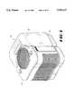
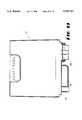
- FIG. 1is a perspective view of an evaporative humidifier incorporating the principles of the present invention.
- FIG. 2is a top plan view of an evaporative humidifier incorporating the principles of the present invention and illustrating an air outlet grill located in a top cover portion positioned adjacent to a water reservoir tank.
- FIG. 3is a side elevation view of the evaporative humidifier illustrating an air inlet grill located in a side of the top cover which is removably mounted on the base platform.
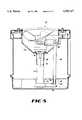
- FIG. 4is a cross-sectional view of the humidifier, taken along line 4--4 in FIG. 2.
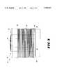
- FIG. 5is a cross-sectional view of the humidifier, taken along line 5--5 in FIG. 2.
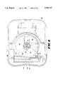
- FIG. 6is a top plan view of the humidifier with the uppermost portion of the top cover of the humidifier removed for purposes of illustration to view the internal components of the humidifier.
- FIG. 7is a detailed view of the water tank reservoir and its operation for release of water into the base platform.
- FIG. 8is a cross-sectional view of an alternative embodiment of the present invention illustrating the use of an evaporator panel assembly drawing water from the base platform by capillary action.
- FIG. 9is a bottom plan view of the evaporative humidifier shown in FIGS. 1-7.
- FIG. 10is a side elevation view taken along line 10--10 in FIG. 9.
- an evaporative type humidifier embodying the teachings of the subject inventionis generally designated as 10.
- the term "evaporative humidifier”refers to a humidifier which evaporates water into a forced airstream by drawing a flow of air through a water retaining element disposed within the humidifier.
- the humidifierincludes a top cover 12, a water reservoir tank 14 and a base platform 16. The top cover 12 and the reservoir tank 14 are removably mounted on the base platform 16.
- the base platform 16is made of molded plastic, which may be formed by either injection molding or blow molding.
- Base platform 16is formed from a material, preferably plastic, which contains a biocide or antimicrobial agent for the purpose of resisting or retarding the growth of bacteria and fungi throughout all surfaces of base platform 16, including the inner surface 17 of base platform 16 which contacts water as subsequently discussed in greater detail.
- the biocideis incorporated into a polymeric resin prior to the molding process.
- the biocide-containing polymeric resinis then molded into the desired shape of base platform 16. As a result of this process the biocide is substantially uniformly distributed throughout the plastic used to construct base platform 16.
- base platform 16provides anti-bacterial and anti-fungal protection throughout base platform 16, as opposed to localized areas for instance, and provides this protection in a maintenance-free manner throughout the service life of humidifier 10.
- the base platformis preferably made of injection or blow molded polypropylene.
- base platform 16may be formed from any plastic or other material which is compatible with biocide incorporation.
- the biocidemay comprise 10, 10'-oxybisphenox-arsine, available under the tradename VINYZENE from Morton International; zinc pyrithione, available from Olin Corporation, under the tradename zinc OMADINE; 2,4,4-trichloro-2'-hydroxydiphenyl ether, available from Microban Co., under the tradename MICROBAN Additive B, and also available from Ciba-Geigy Corporation, under the tradename IRGASAN DP 300; or other antimicrobial agents which are physically and chemically compatible with the polymer or plastic material of construction of the base platform 16.
- VINYZENEis preferred due to manufacturing cost considerations and to the somewhat enhanced effectiveness of VINYZENE in resisting the growth of certain microorganisms.
- Top cover 12includes two electrical switches 18 and 20.
- the switches 18 and 20control the speed of the fan located inside of the top cover 12 and the humidity of the air forced through air outlet grill 22 located in the upper surface 24 of the top cover, respectively.
- Reservoir tank 14includes leg portions 26 and 28, and a cross piece 30 interconnecting leg portions 26 and 28. Leg portions 26 and 28, and cross piece 30 are configured so as to form an overall U-shape of reservoir tank 14, and a recess 32 which is spanned by a handle 34.
- the operator of humidifier 10may lift and carry tank 14 in an inverted position by grasping the handle 34.
- the tank 14may also include a second handle 35 (shown in FIGS. 9 and 10) disposed about the top portion of the tank which provides a means for carrying tank 14 in an upright position. The use of the two handles 34 and 35 facilitate filling tank 14 with water.
- a foot 37is integrally formed with the handle 35 and is attached to a top portion of tank 14.
- Foot 37may be used to support tank 14 in an inverted position (in conjunction with a subsequently discussed cap 180 of tank 14) after removing tank 14 from base platform 16.
- the curvature of the leg portions 26, 28 and cross piece 30follow the contour of the top cover 12 and the semicircular projection formed by the air outlet grill 22 which extends along the height of the top cover 12.
- Humidifier 10further includes an air inlet grill 38, which is disposed in a sidewall 36 of the top cover 12. Grill 38 allows passage of air into the interior of the top cover 12. In the illustrated embodiment shown in FIG. 3, a lowermost edge portion 40 of the air inlet grill 38 is located slightly above the lowermost visible edge 42 of the top cover 12 which is seated on an uppermost edge 44 of base platform 16. The top cover 12 extends into the base platform 16 to provide a secure removable fit of the top cover 12 on the base platform 16.
- a water supply 50 contained in tank reservoir 14is conveyed along the path indicated by arrows 52 into the bottom of the base platform 16 to form a pool of water 54 to a predetermined depth ranging from about 1 inch to about 1-1/2inches.
- the tank reservoir 14includes a means for maintaining the predetermined depth of the water pool 54, which comprises a spring-biased water release valve 55.
- valve 55which controls the release of water 50 to the base platform 16, will be explained in more detail with reference to FIG. 7.
- tank reservoir 14which is removably mounted on base platform 16, in combination with the periodic dispensing of water from tank 14 to base platform 16 through the spring-biased water release valve 55 allows the predetermined depth of the water pool 54 to be substantially less than the depth of standing water within conventional humidifiers utilizing a tub or base portion of the humidifier as the only water reservoir (ie, without the equivalent of tank 14 and valve 55).
- the water depthmay be significantly greater (on the order of several inches) if the humidifier is filled to a depth accommodating a full day's supply of water for instance.
- the frontal surface area of the evaporator panel 128 which is exposed to air flow discharging from grill 38may be greater than that of the foregoing conventional humidifier having a comparable size. Consequently, the performance of humidifier 10 is better than that of conventional humidifiers. It should be understood that increasing the height of the top cover 12 to accommodate a taller evaporator panel while maintaining the same output of humidifier 10, measured in pounds of water per day, is undesirable due to the increased manufacturing costs associated with such an increase in the size of cover 12.
- humidifier 10further includes a motor assembly 56 comprising a motor 58 which has oppositely directed output shafts 60 and 62.
- a distal end of shaft 60is rotatably coupled with a hub 64 of a fan assembly 65.
- the fan assembly 65further includes a plurality of radially extending fan blades 66 which are mounted on the hub 64. The pitch and radial height of blades 66, as well as the number of blades 66, were optimized for airflow output and noise level to produce an efficient and quiet fan assembly 65.
- the oppositely extending output shaft 62is connected by a coupling 68 to a pump drive shaft 70.
- the coupling 68 and drive shaft 70are housed within a hollow column 72.
- the pump shaft 70extends through a base plate 74 of the column 72 and into a pump assembly 76 having housing parts 78 and 80.
- the pump assembly 76includes a submersible centrifugal pump having an impeller 82 located inside the housing portions 78 and 80.
- Impeller 82includes a plurality of radially extending vanes 84.
- directional line 86upon energization of motor 58 and rotation of the impeller 82, water from the pool of water 54 in communication with inlet 88 is forced tangentially outward to an outlet 90 including a hollow projection 92. Coupled to the projection 92 is one end 94 of an outlet conduit 96. The opposite end 98 of the conduit 96 engages a friction fit conduit or pipe 100 having an elongated downspout opening 102. Accordingly, water is conveyed from the pool of water 54 along the path indicated by direction arrows 104. The elongated opening 102 allows water to fall in the direction of arrows 106 into a diffuser tray 108.
- Elongated opening 102releases water by gravity between the sidewalls 110 of diffuser tray 108.
- a bottom plate 112 of the diffuser trayincludes a plurality of rows 114, 116, 118 and 120 of holes for timed release of the water into a frame 122.
- a top plate of the frame 122is formed by the bottom plate 112 of the diffuser tray 108.
- the frame 122also includes a lower plate 124 having a centrally located elongated opening 126. The opposed sides of the frame are sealed to the top and bottom plates of the frame with the only additional openings of the frame being formed in front panel 127 and rear panel 129 to permit the flow of air therethrough.
- the evaporator panel 128Housed in the frame 122 is an evaporator panel 128.
- the frame 122 and evaporator panel 128combine to form an evaporator panel assembly 125.
- the evaporator panel 128is formed of a plurality of layers of slit and expanded metal, preferably aluminum, having a fired clay-based covering or coating incorporating or containing a biocide. Adjacent layers of the expanded metal, which are bonded to one another, are offset relative to one another to produce a tortuous flowpath for the air passing through panel 128.
- the clay-based coveringcreates a hydrophilic coating which enhances the ability of the evaporator panels to retain water.
- the biocide or antimicrobial agent which is incorporated in the clay-based coatingis preferably zinc OMADINE. However, other biocides may be used which are compatible with the formulation of the clay-based covering.
- panel 128resists the growth of bacteria or fungi on panel 128 and is therefore an integral part of the overall objective of providing a "healthy" humidifier. Additionally, the use of expanded metal to construct panel 128 permits panel 128 to be periodically removed and cleaned if desired in a conventional dish washer for instance.
- Panel 128may alternatively be constructed of a plurality of slit and expanded layers of plastic, preferably polypropylene, which incorporates a biocide during the fabrication of the polypropylene panel.
- the biocideis preferably VINYZENE but may comprise the alternative antimicrobial agents listed previously with respect to the base platform 16 of humidifier 10.
- a cardboard evaporator panel or paper "wick"may be used in lieu of panel 128.
- An example of a cardboard evaporator panel which may be usedis available under the tradename Polar Pad from Research Products Corporation.
- the cardboard evaporator panel and paper wickpreferably include a biocide or antimicrobial agent.
- a plurality of fingers 144, 146retain the frame 122 in position on the base platform 16.
- the frame 122is removable for replacing or cleaning the evaporator panel 128 housed in frame 122 after a predetermined period of use.
- This mounting arrangement for frame 122also facilitates the use of varying sizes for frame 122 and panel 128.
- the flow rate of the water delivered to the evaporator panel 128is determined by the size and number of holes in rows 114, 116, 118 and 120, which may be optimized for a given application.
- a preferred range of water flow rate into panel 128is about 15 gallons per hour to about 25 gallons per hour.
- the following components of humidifier 10are made of a molded material, preferably polypropylene, and incorporate or contain a biocide or antimicrobial agent uniformly distributed throughout as a result of the same process discussed previously with respect to base platform 16: housing parts 78 and 80 of pump assembly 76; pump impeller 82; hollow column 72; outlet conduit 96; pipe 100; and frame 122. Any plastic or other material which is compatible with biocide incorporation may also be used to form these components of humidifier 10.
- the preferred biocide for these componentsis VINYZENE but may comprise the alternative biocides discussed previously with respect to base platform 16.
- the preferred concentration of the biocideranges from about 0.6% to about 2% by weight, with the most preferred concentration being about 1% by weight.
- humidifier 10functions to humidify the air in the environment surrounding humidifier 10. This is effectuated by supplying water to base platform 16 via tank reservoir 14 and valve 55 and energizing motor 58 which produces simultaneous rotation of the impeller 82 of pump assembly 76 and the blades 66 of assembly fan 65. Rotation of the impeller 82 results in water being delivered to the top of evaporator panel 128, with the water then flowing downward through panel 128 as discussed previously.
- a preferred range of airflow through humidifier 10is 90 to 165 scfm (standard cubic feet per minute) which corresponds to an output of 2 to 5 gallons of water per day.
- the fan speed control switch 18regulates the speed of fan assembly 65 between an off, low and high speed position.
- the humidistat, or switch 20allows the operator to control the humidity level. Upon reaching a predetermined percentage of humidity, current to the motor 58 is interrupted until the humidity in the surrounding environment falls below the predetermined humidity set point. A preferred range of humidity is about 30% to about 40%.
- a baffle plate 136defines an upper boundary of the flowpath for the air entering humidifier 10 through grill 38.
- baffle plate 136moves through the opening in the front panel 124 of the frame 122 to pass through the tortuous flowpath of the evaporator panel 128, which may vary with the material of the evaporator panel.
- the air passing through the evaporator panel 128causes water located in the evaporator panel 128 to be evaporated and introduced into the air stream.
- This humidified airis then continuously drawn out of the evaporator panel 128 and passed through a conically shaped grill 143 to exit the top cover through the outlet grill 22. Humidity is thereby introduced into the environment surrounding humidifier 10.
- Grill 22includes a plurality of spaced slats or struts 23 which may have a variable orientation relative to vertical to direct the air discharging from grill 22 away from the inhabitants of the environment surrounding humidifier 10 if desired.
- source of water 50 in reservoir tank 14is introduced into the base platform 16 in a direction of directional line 150.
- an evaporator panel 152is housed in a frame 154.
- Panel 152is a "wick"-type water retaining element constructed of paper.
- a lowermost portion 156 of the water retaining element 152is positioned to extend into a pool of water 158 formed in the base platform 16.
- a non-perforated top plate 162 of the frame 152is sealed with the sides of the frame 152 and includes openings in the front panel 164 and rear panel 166.
- openings 170are provided to allow free flow of water up into the water retaining element 152. Since water is transferred to the water retaining element 152 by capillary action, the pump assembly 76 of the prior embodiment and the associated water transfer conduits are eliminated.
- frame 154is preferably made of a molded plastic having a biocide uniformly distributed throughout as discussed previously with respect to frame 122 of the prior embodiment.
- the structure and function of the embodiment illustrated in FIG. 8is otherwise the same as that discussed with respect to the embodiment of FIGS. 1-7, 9, and 10.
- FIG. 7the details of the supply of water 50 to the base platform 16 are shown.
- the tank 14is shown in an inverted position, as compared to a filling position.
- the cap 180is unscrewed from an opening defined by a sidewall 182. Water is poured into the opening until the tank 14 is full. The cap 180 is then secured back onto the tank 14, thereby sealing tank 14, and the tank 14 is inverted.
- the size of the water reservoir tank 14may be varied to accommodate different sized volumes to be humidified. For example, a 2.0, 2.5, 3.0, 3.5, 4.0 or 5.0 gallon tank may be used to humidify corresponding living spaces or volumes having standard 8 foot high ceilings and living areas of approximately 1100, 1300, 1500, 1600, 1800, and 2000 square feet, respectively.
- Tank 14is preferably made of a lightweight, durable material such as a plastic, or any other material suitable for holding water.
- the material of construction of tank 14preferably incorporates or contains a biocide to resist the growth of bacteria and fungi. Since it is desirable to view the contents of tank 14 to determine the water level therein, tank 14 may be constructed of a transparent material such as a plastic in the styrene family. Tank 14 remains sealed except during the periodic release of water to base platform 16 via valve 55. This feature assists in resisting or retarding the growth of bacteria and fungi within tank 14 since the water within tank 14 is not subjected to continuous contamination from airborne microorganisms.
- the spring-biased water release valve 55which is effective for maintaining or controlling the predetermined depth of the water pool 54 in base platform 16, is mounted in a cylindrical portion 186 defined in the cap 180.
- Valve 55includes a reciprocal plunger 184 mounted in the cylindrical portion 186 and a tapered flange 188 which is mounted at one end of a shaft 190.
- Shaft 190is retained by sleeve 192 which is fixed to the cap 180.
- a spring 194is schematically shown surrounding the shaft 190 and having one end abutting the sleeve 192 and the opposite end abutting a plate 196 located at the opposite end of shaft 190 from the flange 188.
- the tank 14When all the water 50 is removed from the reservoir tank 14, the tank 14 may be lifted by handle 34. An indication that the water supply has been depleted may be provided by an optional float mechanism (not shown) within base platform 16 which may trigger an indicator such as a light (not shown) for instance. This mechanism may also interrupt the electricity provided to motor 58.
- plate 196Upon removal of tank 14, plate 196 does not contact the projection 198, and spring 194 biases flange 188 to seat against cylindrical portion 186, thereby sealing the tank 14. This is important because when the tank 14 is again filled with water and inverted prior to placement on the base platform 16, it is necessary that the water in the tank 14 be sealed in place by flange 188.
- the illustrative embodiments of the present inventionhave been shown to include a single reservoir tank 14, it is contemplated as being within the scope of the present invention to utilize a plurality of vertically stacked tanks 14 within humidifier 10.
- the use of multiple tanks 14may provide increased water capacity and/or distribute the total water weight among the tanks 14, thereby facilitating the transport of each individual tank 14.
- a tap line from a water pipemay be disposed in fluid communication with a single tank 14 or an upper one of a plurality of tanks 14. Release of water from the tap line may then be controlled by a float valve, for example, to only allow passage of water to the corresponding tank 14 due to a reduction of the water level within the tank 14.
Landscapes
- Engineering & Computer Science (AREA)
- Chemical & Material Sciences (AREA)
- Combustion & Propulsion (AREA)
- Mechanical Engineering (AREA)
- General Engineering & Computer Science (AREA)
- Air Humidification (AREA)
Abstract
Description
Claims (47)
Priority Applications (2)
| Application Number | Priority Date | Filing Date | Title |
|---|---|---|---|
| US08/780,850US5783117A (en) | 1997-01-09 | 1997-01-09 | Evaporative humidifier |
| CA002226816ACA2226816A1 (en) | 1997-01-09 | 1998-01-13 | Evaporative humidifier |
Applications Claiming Priority (1)
| Application Number | Priority Date | Filing Date | Title |
|---|---|---|---|
| US08/780,850US5783117A (en) | 1997-01-09 | 1997-01-09 | Evaporative humidifier |
Publications (1)
| Publication Number | Publication Date |
|---|---|
| US5783117Atrue US5783117A (en) | 1998-07-21 |
Family
ID=25120897
Family Applications (1)
| Application Number | Title | Priority Date | Filing Date |
|---|---|---|---|
| US08/780,850Expired - Fee RelatedUS5783117A (en) | 1997-01-09 | 1997-01-09 | Evaporative humidifier |
Country Status (2)
| Country | Link |
|---|---|
| US (1) | US5783117A (en) |
| CA (1) | CA2226816A1 (en) |
Cited By (132)
| Publication number | Priority date | Publication date | Assignee | Title |
|---|---|---|---|---|
| US6053482A (en)* | 1997-01-31 | 2000-04-25 | Holmes Products Corp. | Humidifier including a water filtration device |
| US6070808A (en)* | 1998-05-18 | 2000-06-06 | Hygeian Technologies, Ltd. | Mobile spraying and cleaning apparatus |
| US6131889A (en)* | 1998-12-18 | 2000-10-17 | Honeywell, Inc. | Evaporative humidifier with liquid distribution system |
| US6165243A (en)* | 1998-06-22 | 2000-12-26 | Hagihara Industries Inc. | Anti-mold and anti-bacteria air filter |
| WO2001036879A1 (en)* | 1999-11-15 | 2001-05-25 | Honeywell Inc. | Filter with handle feature |
| US6257560B1 (en) | 1999-06-04 | 2001-07-10 | Kevin Kim | Fountain humidifier and air cleanser |
| USD449097S1 (en) | 2000-05-01 | 2001-10-09 | Hamilton Beach/Proctor-Silex, Inc. | Air cleaner |
| USD449676S1 (en) | 2000-08-11 | 2001-10-23 | Hamilton Beach/Proctor-Silex, Inc. | Humidifier |
| USD449679S1 (en) | 2000-05-01 | 2001-10-23 | Hamilton Beach/Proctor-Silex, Inc. | Air cleaner filter |
| US6315821B1 (en) | 2000-05-03 | 2001-11-13 | Hamilton Beach/Proctor-Silex, Inc. | Air filtration device including filter change indicator |
| US6328791B1 (en) | 2000-05-03 | 2001-12-11 | Hamilton Beach/Proctor-Silex, Inc. | Air filtration device |
| USD459457S1 (en) | 2000-05-01 | 2002-06-25 | Hamilton Beach/Proctor-Silex, Inc. | Air cleaner |
| US6427984B1 (en) | 2000-08-11 | 2002-08-06 | Hamilton Beach/Proctor-Silex, Inc. | Evaporative humidifier |
| US6494940B1 (en) | 2000-09-29 | 2002-12-17 | Hamilton Beach/Proctor-Silex, Inc. | Air purifier |
| USD468820S1 (en) | 2000-09-29 | 2003-01-14 | Hamilton Beach/Proctor-Silex, Inc. | Air purifier |
| US20030034573A1 (en)* | 2001-08-14 | 2003-02-20 | Hamilton Beach/Proctor-Silex, Inc. | Humidifier filter servicing and water level indicator |
| US6622993B2 (en) | 2000-10-30 | 2003-09-23 | Hamilton Beach/Proctor-Silex, Inc. | Humidifier including output efficiency and liquid level indicators |
| US20040045909A1 (en)* | 2002-07-08 | 2004-03-11 | Matsushita Electric Industrial Co., Ltd. | Humidifier |
| US20040081578A1 (en)* | 2001-12-10 | 2004-04-29 | Adams Dan L. | Biocide impregnation of coatings for ESP components |
| US20040082492A1 (en)* | 2001-02-26 | 2004-04-29 | Urs Kohler | Biocidal plastics internal elements for mass transfer apparatus |
| US20040178518A1 (en)* | 2003-03-14 | 2004-09-16 | Keller Kevin Eugene | Evaporative humidifier with water distribution system |
| US6832753B1 (en)* | 2003-08-28 | 2004-12-21 | Royal-G Enterprise Co., Ltd. | Humidifier with a water wheel device |
| US20050001338A1 (en)* | 2003-07-01 | 2005-01-06 | Helgo Hagemann | Built-in element for a cooling tower |
| US6845971B2 (en) | 2001-06-18 | 2005-01-25 | Slant/Fin Corporation | Sterile humidifier and method of operating same |
| US20050067723A1 (en)* | 2003-09-25 | 2005-03-31 | Parker Kenneth R. | Microorganism-resistant humidifier |
| US20050133942A1 (en)* | 2003-12-19 | 2005-06-23 | Rps Products, Inc. | Cartridge humidifier |
| US20050151280A1 (en)* | 2004-01-09 | 2005-07-14 | Jon French | Humidifier |
| US20050200031A1 (en)* | 2004-02-09 | 2005-09-15 | Campbell Glennbruce S. | Humidifier with safety reservoir |
| US20050258554A1 (en)* | 2004-05-24 | 2005-11-24 | Slant/Fin Corporation | Humidifier with improved UV disinfection |
| US20060163754A1 (en)* | 2005-01-26 | 2006-07-27 | Stephen Barthelson | Humidifier |
| US20070095941A1 (en)* | 2005-11-03 | 2007-05-03 | Gorres Geoffrey H | Scent dispensing apparatus |
| US20070224079A1 (en)* | 2006-03-22 | 2007-09-27 | Zimek Technologies Ip, Llc | Ultrasonic Sanitation Device and Associated Methods |
| US20070224080A1 (en)* | 2006-03-22 | 2007-09-27 | Zimek Technologies Ip, Llc | Ultrasonic Sanitation Device and Associated Methods |
| US7368003B2 (en) | 2005-06-24 | 2008-05-06 | S.C. Johnson & Son, Inc. | Systems for and methods of providing air purification in combination with odor elimination |
| US20080226495A1 (en)* | 2006-03-22 | 2008-09-18 | Zimek Technologies Ip, Llc | Ultrasonic Sanitation and Disinfecting Device and Associated Methods |
| WO2008077215A3 (en)* | 2006-12-22 | 2009-04-02 | Springer Carrier Ltda | Top cover snap fit |
| WO2008077213A3 (en)* | 2006-12-22 | 2009-04-02 | Springer Carrier Ltda | Evaporator scroll securement for an air conditioner |
| US7537647B2 (en) | 2005-08-10 | 2009-05-26 | S.C. Johnson & Son, Inc. | Air purifier |
| US20100192951A1 (en)* | 2007-07-18 | 2010-08-05 | Dongsheng Dong | Oxygen humidification and delivery device |
| US20100226751A1 (en)* | 2009-03-04 | 2010-09-09 | Dyson Technology Limited | Fan assembly |
| US20100225012A1 (en)* | 2009-03-04 | 2010-09-09 | Dyson Technology Limited | Humidifying apparatus |
| US20100226749A1 (en)* | 2009-03-04 | 2010-09-09 | Dyson Technology Limited | Fan assembly |
| US20100258958A1 (en)* | 2007-09-18 | 2010-10-14 | Raymond Industrial Limited | Humidifier |
| WO2011050041A1 (en)* | 2009-10-20 | 2011-04-28 | Kaz Europe Sa | Uv sterilization chamber for a humidifier |
| US20110164959A1 (en)* | 2008-09-23 | 2011-07-07 | Dyson Technology Limited | Fan |
| US20110223015A1 (en)* | 2007-09-04 | 2011-09-15 | Dyson Technology Limited | Fan |
| US20110221078A1 (en)* | 2010-03-12 | 2011-09-15 | Mordechai Lev | Humidifier |
| US8308432B2 (en) | 2009-03-04 | 2012-11-13 | Dyson Technology Limited | Fan assembly |
| US8348597B2 (en) | 2009-03-04 | 2013-01-08 | Dyson Technology Limited | Fan assembly |
| US8366403B2 (en) | 2010-08-06 | 2013-02-05 | Dyson Technology Limited | Fan assembly |
| US8403640B2 (en) | 2009-03-04 | 2013-03-26 | Dyson Technology Limited | Fan assembly |
| US8408869B2 (en) | 2009-03-04 | 2013-04-02 | Dyson Technology Limited | Fan assembly |
| US8430624B2 (en) | 2009-03-04 | 2013-04-30 | Dyson Technology Limited | Fan assembly |
| US20130118492A1 (en)* | 2007-06-07 | 2013-05-16 | Resmed Limited | Tub for humidifier |
| US8454322B2 (en) | 2009-11-06 | 2013-06-04 | Dyson Technology Limited | Fan having a magnetically attached remote control |
| US8469658B2 (en) | 2009-03-04 | 2013-06-25 | Dyson Technology Limited | Fan |
| US8469660B2 (en) | 2009-03-04 | 2013-06-25 | Dyson Technology Limited | Fan assembly |
| GB2500009A (en)* | 2012-03-06 | 2013-09-11 | Dyson Technology Ltd | Humidifying apparatus |
| US8613601B2 (en) | 2009-03-04 | 2013-12-24 | Dyson Technology Limited | Fan assembly |
| US8701701B2 (en)* | 2012-09-25 | 2014-04-22 | Chin-Cheng Huang | Float switch of a humidifier |
| US8714937B2 (en) | 2009-03-04 | 2014-05-06 | Dyson Technology Limited | Fan assembly |
| US8734094B2 (en) | 2010-08-06 | 2014-05-27 | Dyson Technology Limited | Fan assembly |
| US8770946B2 (en) | 2010-03-23 | 2014-07-08 | Dyson Technology Limited | Accessory for a fan |
| US8784071B2 (en) | 2009-03-04 | 2014-07-22 | Dyson Technology Limited | Fan assembly |
| JP2014142128A (en)* | 2013-01-24 | 2014-08-07 | Panasonic Corp | Humidifier and air cleaner with humidification function |
| US8873940B2 (en) | 2010-08-06 | 2014-10-28 | Dyson Technology Limited | Fan assembly |
| US8882451B2 (en) | 2010-03-23 | 2014-11-11 | Dyson Technology Limited | Fan |
| US8894354B2 (en) | 2010-09-07 | 2014-11-25 | Dyson Technology Limited | Fan |
| US8905384B2 (en) | 2011-04-24 | 2014-12-09 | Jeri Rodrigs | Room vent humidifier |
| US8967979B2 (en) | 2010-10-18 | 2015-03-03 | Dyson Technology Limited | Fan assembly |
| US8967980B2 (en) | 2010-10-18 | 2015-03-03 | Dyson Technology Limited | Fan assembly |
| US9011116B2 (en) | 2010-05-27 | 2015-04-21 | Dyson Technology Limited | Device for blowing air by means of a nozzle assembly |
| USD728092S1 (en) | 2013-08-01 | 2015-04-28 | Dyson Technology Limited | Fan |
| USD728769S1 (en) | 2013-08-01 | 2015-05-05 | Dyson Technology Limited | Fan |
| USD728770S1 (en) | 2013-08-01 | 2015-05-05 | Dyson Technology Limited | Fan |
| USD729373S1 (en) | 2013-03-07 | 2015-05-12 | Dyson Technology Limited | Fan |
| USD729376S1 (en) | 2013-03-07 | 2015-05-12 | Dyson Technology Limited | Fan |
| USD729372S1 (en) | 2013-03-07 | 2015-05-12 | Dyson Technology Limited | Fan |
| USD729374S1 (en) | 2013-03-07 | 2015-05-12 | Dyson Technology Limited | Fan |
| USD729375S1 (en) | 2013-03-07 | 2015-05-12 | Dyson Technology Limited | Fan |
| USD729925S1 (en) | 2013-03-07 | 2015-05-19 | Dyson Technology Limited | Fan |
| US9127689B2 (en) | 2009-03-04 | 2015-09-08 | Dyson Technology Limited | Fan assembly |
| US9127855B2 (en) | 2011-07-27 | 2015-09-08 | Dyson Technology Limited | Fan assembly |
| US9151299B2 (en) | 2012-02-06 | 2015-10-06 | Dyson Technology Limited | Fan |
| CN103292405B (en)* | 2008-05-20 | 2015-11-18 | 福智海研究院 | Air purification humidifier |
| USD746425S1 (en) | 2013-01-18 | 2015-12-29 | Dyson Technology Limited | Humidifier |
| USD746966S1 (en) | 2013-01-18 | 2016-01-05 | Dyson Technology Limited | Humidifier |
| USD747450S1 (en) | 2013-01-18 | 2016-01-12 | Dyson Technology Limited | Humidifier |
| US9249809B2 (en) | 2012-02-06 | 2016-02-02 | Dyson Technology Limited | Fan |
| USD749231S1 (en) | 2013-01-18 | 2016-02-09 | Dyson Technology Limited | Humidifier |
| US9283573B2 (en) | 2012-02-06 | 2016-03-15 | Dyson Technology Limited | Fan assembly |
| US9328739B2 (en) | 2012-01-19 | 2016-05-03 | Dyson Technology Limited | Fan |
| US9366449B2 (en) | 2012-03-06 | 2016-06-14 | Dyson Technology Limited | Humidifying apparatus |
| US9410711B2 (en) | 2013-09-26 | 2016-08-09 | Dyson Technology Limited | Fan assembly |
| US9458853B2 (en) | 2011-07-27 | 2016-10-04 | Dyson Technology Limited | Fan assembly |
| US9513028B2 (en) | 2009-03-04 | 2016-12-06 | Dyson Technology Limited | Fan assembly |
| US9568006B2 (en) | 2012-05-16 | 2017-02-14 | Dyson Technology Limited | Fan |
| US9568021B2 (en) | 2012-05-16 | 2017-02-14 | Dyson Technology Limited | Fan |
| US9599356B2 (en) | 2014-07-29 | 2017-03-21 | Dyson Technology Limited | Humidifying apparatus |
| USD791925S1 (en)* | 2015-07-13 | 2017-07-11 | Samsung Electronics Co., Ltd | Water box for dehumidifier |
| US9732763B2 (en) | 2012-07-11 | 2017-08-15 | Dyson Technology Limited | Fan assembly |
| US9745981B2 (en) | 2011-11-11 | 2017-08-29 | Dyson Technology Limited | Fan assembly |
| US9745996B2 (en) | 2010-12-02 | 2017-08-29 | Dyson Technology Limited | Fan |
| US9752789B2 (en) | 2012-03-06 | 2017-09-05 | Dyson Technology Limited | Humidifying apparatus |
| CN107166567A (en)* | 2014-07-03 | 2017-09-15 | 青岛海尔空调器有限总公司 | air treatment system |
| US9797612B2 (en) | 2013-01-29 | 2017-10-24 | Dyson Technology Limited | Fan assembly |
| US9797613B2 (en) | 2012-03-06 | 2017-10-24 | Dyson Technology Limited | Humidifying apparatus |
| US9797414B2 (en) | 2013-07-09 | 2017-10-24 | Dyson Technology Limited | Fan assembly |
| US9816531B2 (en) | 2008-10-25 | 2017-11-14 | Dyson Technology Limited | Fan utilizing coanda surface |
| US9822778B2 (en) | 2012-04-19 | 2017-11-21 | Dyson Technology Limited | Fan assembly |
| US9903602B2 (en) | 2014-07-29 | 2018-02-27 | Dyson Technology Limited | Humidifying apparatus |
| US9926804B2 (en) | 2010-11-02 | 2018-03-27 | Dyson Technology Limited | Fan assembly |
| US9927136B2 (en) | 2012-03-06 | 2018-03-27 | Dyson Technology Limited | Fan assembly |
| US9982677B2 (en) | 2014-07-29 | 2018-05-29 | Dyson Technology Limited | Fan assembly |
| US10092874B2 (en)* | 2014-09-03 | 2018-10-09 | Lg Electronics Inc. | Air washer |
| US10094392B2 (en) | 2011-11-24 | 2018-10-09 | Dyson Technology Limited | Fan assembly |
| US10100836B2 (en) | 2010-10-13 | 2018-10-16 | Dyson Technology Limited | Fan assembly |
| US10145583B2 (en) | 2012-04-04 | 2018-12-04 | Dyson Technology Limited | Heating apparatus |
| US10408478B2 (en) | 2012-03-06 | 2019-09-10 | Dyson Technology Limited | Humidifying apparatus |
| US10428837B2 (en) | 2012-05-16 | 2019-10-01 | Dyson Technology Limited | Fan |
| US10465928B2 (en) | 2012-03-06 | 2019-11-05 | Dyson Technology Limited | Humidifying apparatus |
| US10612565B2 (en) | 2013-01-29 | 2020-04-07 | Dyson Technology Limited | Fan assembly |
| EP3647671A1 (en)* | 2018-11-02 | 2020-05-06 | Koninklijke Philips N.V. | Water supply system and method of supplying water |
| CN111397058A (en)* | 2019-01-02 | 2020-07-10 | 戴森技术有限公司 | air handling unit |
| JP2021006752A (en)* | 2019-06-28 | 2021-01-21 | ダイニチ工業株式会社 | Water tank and humidifier |
| US20210190342A1 (en)* | 2019-12-18 | 2021-06-24 | Shenzhen Chenbei Technology Co., Ltd. | Humidifier with Air Guiding Arrangement |
| US20220357054A1 (en)* | 2020-02-07 | 2022-11-10 | Daikin Industries, Ltd. | Air treatment device |
| US11549699B2 (en)* | 2017-10-03 | 2023-01-10 | Vornado Air, Llc | Portable humidifier |
| US20230136098A1 (en)* | 2021-11-02 | 2023-05-04 | Shenzhen Miaoxin Technology Co., Ltd | Humidifier |
| US20240165652A1 (en)* | 2020-06-26 | 2024-05-23 | Armstrong World Industries, Inc. | Coating humidification system |
| US12044436B2 (en) | 2019-01-02 | 2024-07-23 | Dyson Technology Limited | Air treatment apparatus |
| US12298034B2 (en) | 2019-01-02 | 2025-05-13 | Dyson Technology Limited | Air treatment apparatus |
Families Citing this family (1)
| Publication number | Priority date | Publication date | Assignee | Title |
|---|---|---|---|---|
| CN108981051A (en)* | 2018-07-23 | 2018-12-11 | 珠海格力电器股份有限公司 | Humidifying apparatus and control method of humidifying apparatus |
Citations (29)
| Publication number | Priority date | Publication date | Assignee | Title |
|---|---|---|---|---|
| US3497453A (en)* | 1967-07-25 | 1970-02-24 | Alfred Yurdin | Method and apparatus for protection of power humidifier |
| US3610589A (en)* | 1968-09-30 | 1971-10-05 | Gen Electric Canada | Humidifier |
| US3738621A (en)* | 1969-11-10 | 1973-06-12 | Everkool Inc | Evaporative cooler |
| DE2357746A1 (en)* | 1973-11-20 | 1975-05-28 | Luftbefeuchtung Gmbh | Humidifier with automatic cut-out when water level falls - prevents solid residues passing into the filter system |
| US4276241A (en)* | 1978-06-29 | 1981-06-30 | White-Westinghouse Corporation | Dispenser-liquid water treatment for room humidifier |
| NL8200083A (en)* | 1981-02-09 | 1982-09-01 | Plaston Ag | HUMIDIFIER WITH EVAPORATION AND FORCED CIRCULATION. |
| US4400185A (en)* | 1980-11-28 | 1983-08-23 | Goettl Adam D | Evaporative cooler with improved air handling mechanism |
| US4466422A (en)* | 1983-03-03 | 1984-08-21 | Lahiri Samir C | Humidifier and air circulator |
| US4499031A (en)* | 1982-09-27 | 1985-02-12 | Allis-Chalmers Corp. | Evaporative gas treating system |
| US4631297A (en)* | 1984-03-12 | 1986-12-23 | Dow Corning Corporation | Antimicrobially effective organic foams and methods for their preparation |
| US4701286A (en)* | 1985-06-14 | 1987-10-20 | Applied Biochemists Inc. | Apparatus for dispensing a water treating composition into the recirculating water of an evaporative system |
| US4708832A (en)* | 1984-01-20 | 1987-11-24 | Aktiebolaget Carl Munters | Contact body |
| US4805793A (en)* | 1987-10-23 | 1989-02-21 | Pioneer/Eclipse Corporation | Stackable bottle |
| US4822533A (en)* | 1986-12-11 | 1989-04-18 | Emerson Electric Co. | Humidifier with floating wick assembly and replaceable wick elements |
| US5037583A (en)* | 1990-04-23 | 1991-08-06 | Bemis Manufacturing Company | Humidifier |
| US5061405A (en)* | 1990-02-12 | 1991-10-29 | Emerson Electric Co. | Constant humidity evaporative wicking filter humidifier |
| US5086494A (en)* | 1990-12-10 | 1992-02-04 | Duracraft Corporation | Leak proof humidifier |
| US5110511A (en)* | 1990-06-29 | 1992-05-05 | Bemis Manufacturing Company | Humidifier |
| US5133904A (en)* | 1990-10-17 | 1992-07-28 | Bemis Manufacturing Company | Humidifier |
| US5247604A (en)* | 1992-04-20 | 1993-09-21 | Duracraft Corporation | Humidifier tank with leakage control cap |
| US5374381A (en)* | 1992-11-10 | 1994-12-20 | Rps Products, Inc. | Evaporative element for a humidifier and method of making the same |
| USD362906S (en) | 1994-11-25 | 1995-10-03 | Duracraft Corporation | Evaporative humidifier |
| US5460718A (en)* | 1994-04-08 | 1995-10-24 | Micasa Trading Corporation | Domestic water treating device including permanent magnet means |
| US5480588A (en)* | 1994-12-05 | 1996-01-02 | Emerson Electric Co. | Humidifier with exposed spaced bottles |
| US5483616A (en)* | 1994-12-21 | 1996-01-09 | Duracraft Corporation | Humidifier tank with improved handle |
| USRE35153E (en)* | 1990-04-17 | 1996-02-06 | Duracraft Corporation | Humidifier with float activated water level responsive turn off |
| US5490957A (en)* | 1994-09-28 | 1996-02-13 | Lasko; William E. | Portable humidifier |
| US5529726A (en)* | 1994-04-04 | 1996-06-25 | Holmes Products Corp. | Evaporative humidifier |
| US5547615A (en)* | 1995-05-10 | 1996-08-20 | Duracraft Corporation | Portable humidifier with bacteriastat dispenser |
- 1997
- 1997-01-09USUS08/780,850patent/US5783117A/ennot_activeExpired - Fee Related
- 1998
- 1998-01-13CACA002226816Apatent/CA2226816A1/ennot_activeAbandoned
Patent Citations (30)
| Publication number | Priority date | Publication date | Assignee | Title |
|---|---|---|---|---|
| US3497453A (en)* | 1967-07-25 | 1970-02-24 | Alfred Yurdin | Method and apparatus for protection of power humidifier |
| US3610589A (en)* | 1968-09-30 | 1971-10-05 | Gen Electric Canada | Humidifier |
| US3738621A (en)* | 1969-11-10 | 1973-06-12 | Everkool Inc | Evaporative cooler |
| DE2357746A1 (en)* | 1973-11-20 | 1975-05-28 | Luftbefeuchtung Gmbh | Humidifier with automatic cut-out when water level falls - prevents solid residues passing into the filter system |
| US4276241A (en)* | 1978-06-29 | 1981-06-30 | White-Westinghouse Corporation | Dispenser-liquid water treatment for room humidifier |
| US4400185A (en)* | 1980-11-28 | 1983-08-23 | Goettl Adam D | Evaporative cooler with improved air handling mechanism |
| NL8200083A (en)* | 1981-02-09 | 1982-09-01 | Plaston Ag | HUMIDIFIER WITH EVAPORATION AND FORCED CIRCULATION. |
| US4499031A (en)* | 1982-09-27 | 1985-02-12 | Allis-Chalmers Corp. | Evaporative gas treating system |
| US4466422A (en)* | 1983-03-03 | 1984-08-21 | Lahiri Samir C | Humidifier and air circulator |
| US4708832A (en)* | 1984-01-20 | 1987-11-24 | Aktiebolaget Carl Munters | Contact body |
| US4631297A (en)* | 1984-03-12 | 1986-12-23 | Dow Corning Corporation | Antimicrobially effective organic foams and methods for their preparation |
| US4701286A (en)* | 1985-06-14 | 1987-10-20 | Applied Biochemists Inc. | Apparatus for dispensing a water treating composition into the recirculating water of an evaporative system |
| US4865775A (en)* | 1986-12-11 | 1989-09-12 | Emerson Electric Co. | Humidifier with floating wick assembly |
| US4822533A (en)* | 1986-12-11 | 1989-04-18 | Emerson Electric Co. | Humidifier with floating wick assembly and replaceable wick elements |
| US4805793A (en)* | 1987-10-23 | 1989-02-21 | Pioneer/Eclipse Corporation | Stackable bottle |
| US5061405A (en)* | 1990-02-12 | 1991-10-29 | Emerson Electric Co. | Constant humidity evaporative wicking filter humidifier |
| USRE35153E (en)* | 1990-04-17 | 1996-02-06 | Duracraft Corporation | Humidifier with float activated water level responsive turn off |
| US5037583A (en)* | 1990-04-23 | 1991-08-06 | Bemis Manufacturing Company | Humidifier |
| US5110511A (en)* | 1990-06-29 | 1992-05-05 | Bemis Manufacturing Company | Humidifier |
| US5133904A (en)* | 1990-10-17 | 1992-07-28 | Bemis Manufacturing Company | Humidifier |
| US5086494A (en)* | 1990-12-10 | 1992-02-04 | Duracraft Corporation | Leak proof humidifier |
| US5247604A (en)* | 1992-04-20 | 1993-09-21 | Duracraft Corporation | Humidifier tank with leakage control cap |
| US5374381A (en)* | 1992-11-10 | 1994-12-20 | Rps Products, Inc. | Evaporative element for a humidifier and method of making the same |
| US5529726A (en)* | 1994-04-04 | 1996-06-25 | Holmes Products Corp. | Evaporative humidifier |
| US5460718A (en)* | 1994-04-08 | 1995-10-24 | Micasa Trading Corporation | Domestic water treating device including permanent magnet means |
| US5490957A (en)* | 1994-09-28 | 1996-02-13 | Lasko; William E. | Portable humidifier |
| USD362906S (en) | 1994-11-25 | 1995-10-03 | Duracraft Corporation | Evaporative humidifier |
| US5480588A (en)* | 1994-12-05 | 1996-01-02 | Emerson Electric Co. | Humidifier with exposed spaced bottles |
| US5483616A (en)* | 1994-12-21 | 1996-01-09 | Duracraft Corporation | Humidifier tank with improved handle |
| US5547615A (en)* | 1995-05-10 | 1996-08-20 | Duracraft Corporation | Portable humidifier with bacteriastat dispenser |
Cited By (196)
| Publication number | Priority date | Publication date | Assignee | Title |
|---|---|---|---|---|
| US6053482A (en)* | 1997-01-31 | 2000-04-25 | Holmes Products Corp. | Humidifier including a water filtration device |
| US6070808A (en)* | 1998-05-18 | 2000-06-06 | Hygeian Technologies, Ltd. | Mobile spraying and cleaning apparatus |
| US6165243A (en)* | 1998-06-22 | 2000-12-26 | Hagihara Industries Inc. | Anti-mold and anti-bacteria air filter |
| US6540807B1 (en)* | 1998-06-22 | 2003-04-01 | Ei Kawaguchi | Anti-mold and anti-bacteria air filter |
| US6131889A (en)* | 1998-12-18 | 2000-10-17 | Honeywell, Inc. | Evaporative humidifier with liquid distribution system |
| US6257560B1 (en) | 1999-06-04 | 2001-07-10 | Kevin Kim | Fountain humidifier and air cleanser |
| WO2001036879A1 (en)* | 1999-11-15 | 2001-05-25 | Honeywell Inc. | Filter with handle feature |
| USD459457S1 (en) | 2000-05-01 | 2002-06-25 | Hamilton Beach/Proctor-Silex, Inc. | Air cleaner |
| USD449097S1 (en) | 2000-05-01 | 2001-10-09 | Hamilton Beach/Proctor-Silex, Inc. | Air cleaner |
| USD449679S1 (en) | 2000-05-01 | 2001-10-23 | Hamilton Beach/Proctor-Silex, Inc. | Air cleaner filter |
| US6315821B1 (en) | 2000-05-03 | 2001-11-13 | Hamilton Beach/Proctor-Silex, Inc. | Air filtration device including filter change indicator |
| US6447587B1 (en) | 2000-05-03 | 2002-09-10 | Hamilton Beach/Proctor-Silex, Inc. | Air filtration device |
| US6712889B2 (en) | 2000-05-03 | 2004-03-30 | Hamilton Beach/Proctor-Silex, Inc. | Air filtration device |
| US6508868B2 (en) | 2000-05-03 | 2003-01-21 | Hamilton Beach/Proctor-Silex, Inc. | Air filtration device including filter change indicator |
| US6328791B1 (en) | 2000-05-03 | 2001-12-11 | Hamilton Beach/Proctor-Silex, Inc. | Air filtration device |
| US6863704B2 (en) | 2000-05-03 | 2005-03-08 | Hamilton Beach/Proctor-Silex, Inc. | Air filtration device |
| US20040012103A1 (en)* | 2000-08-11 | 2004-01-22 | Hamilton Beach/Proctor-Silex, Inc. | Evaporative humidifier |
| US6427984B1 (en) | 2000-08-11 | 2002-08-06 | Hamilton Beach/Proctor-Silex, Inc. | Evaporative humidifier |
| US6715739B2 (en) | 2000-08-11 | 2004-04-06 | Hamilton Beach/Proctor-Silex, Inc. | Evaporative humidifier |
| USD449676S1 (en) | 2000-08-11 | 2001-10-23 | Hamilton Beach/Proctor-Silex, Inc. | Humidifier |
| US6604733B2 (en) | 2000-08-11 | 2003-08-12 | Hamilton Beach/Proctor-Silex, Inc. | Evaporative humidifier |
| US6494940B1 (en) | 2000-09-29 | 2002-12-17 | Hamilton Beach/Proctor-Silex, Inc. | Air purifier |
| USD468820S1 (en) | 2000-09-29 | 2003-01-14 | Hamilton Beach/Proctor-Silex, Inc. | Air purifier |
| US6622993B2 (en) | 2000-10-30 | 2003-09-23 | Hamilton Beach/Proctor-Silex, Inc. | Humidifier including output efficiency and liquid level indicators |
| US20040082492A1 (en)* | 2001-02-26 | 2004-04-29 | Urs Kohler | Biocidal plastics internal elements for mass transfer apparatus |
| US6845971B2 (en) | 2001-06-18 | 2005-01-25 | Slant/Fin Corporation | Sterile humidifier and method of operating same |
| US20030034573A1 (en)* | 2001-08-14 | 2003-02-20 | Hamilton Beach/Proctor-Silex, Inc. | Humidifier filter servicing and water level indicator |
| US6796550B2 (en) | 2001-08-14 | 2004-09-28 | Hamilton Beach/Proctor-Silex, Inc. | Humidifier filter servicing and water level indicator |
| US20040081578A1 (en)* | 2001-12-10 | 2004-04-29 | Adams Dan L. | Biocide impregnation of coatings for ESP components |
| US7144549B2 (en)* | 2001-12-10 | 2006-12-05 | Baker Hughes Incorporated | Biocide impregnation of coatings for ESP components |
| US20040045909A1 (en)* | 2002-07-08 | 2004-03-11 | Matsushita Electric Industrial Co., Ltd. | Humidifier |
| US7754157B2 (en)* | 2002-07-08 | 2010-07-13 | Panasonic Corporation | Humidifier |
| US20040178518A1 (en)* | 2003-03-14 | 2004-09-16 | Keller Kevin Eugene | Evaporative humidifier with water distribution system |
| US6824126B2 (en) | 2003-03-14 | 2004-11-30 | Vornado Air Circulation Systems, Inc. | Evaporative humidifier with water distribution system |
| US20050001338A1 (en)* | 2003-07-01 | 2005-01-06 | Helgo Hagemann | Built-in element for a cooling tower |
| US6832753B1 (en)* | 2003-08-28 | 2004-12-21 | Royal-G Enterprise Co., Ltd. | Humidifier with a water wheel device |
| US20050067723A1 (en)* | 2003-09-25 | 2005-03-31 | Parker Kenneth R. | Microorganism-resistant humidifier |
| US6945519B2 (en) | 2003-09-25 | 2005-09-20 | Sunbeam Products, Inc. | Microorganism-resistant humidifier |
| US20050133942A1 (en)* | 2003-12-19 | 2005-06-23 | Rps Products, Inc. | Cartridge humidifier |
| US7073782B2 (en) | 2004-01-09 | 2006-07-11 | Jcs/Thg, Llc | Humidifier |
| US20060170121A1 (en)* | 2004-01-09 | 2006-08-03 | Jcs/Thg, Llc. | Humidifier |
| US20050151280A1 (en)* | 2004-01-09 | 2005-07-14 | Jon French | Humidifier |
| US7377494B2 (en) | 2004-01-09 | 2008-05-27 | Sunbeam Products, Inc. | Humidifier |
| US7234690B2 (en) | 2004-02-09 | 2007-06-26 | Hunter Fan Company | Humidifier with safety reservoir |
| US20050200031A1 (en)* | 2004-02-09 | 2005-09-15 | Campbell Glennbruce S. | Humidifier with safety reservoir |
| US7513486B2 (en)* | 2004-05-24 | 2009-04-07 | Kaz, Inc. | Humidifier with improved UV disinfection |
| US20050258554A1 (en)* | 2004-05-24 | 2005-11-24 | Slant/Fin Corporation | Humidifier with improved UV disinfection |
| US20060163754A1 (en)* | 2005-01-26 | 2006-07-27 | Stephen Barthelson | Humidifier |
| US7368003B2 (en) | 2005-06-24 | 2008-05-06 | S.C. Johnson & Son, Inc. | Systems for and methods of providing air purification in combination with odor elimination |
| US7537647B2 (en) | 2005-08-10 | 2009-05-26 | S.C. Johnson & Son, Inc. | Air purifier |
| US20070095941A1 (en)* | 2005-11-03 | 2007-05-03 | Gorres Geoffrey H | Scent dispensing apparatus |
| US20080226495A1 (en)* | 2006-03-22 | 2008-09-18 | Zimek Technologies Ip, Llc | Ultrasonic Sanitation and Disinfecting Device and Associated Methods |
| US8062588B2 (en)* | 2006-03-22 | 2011-11-22 | Zimek Technologies Ip, Llc | Ultrasonic sanitation device and associated methods |
| US7959859B2 (en) | 2006-03-22 | 2011-06-14 | Sparks David W | Ultrasonic sanitation device and associated methods |
| US8609029B2 (en) | 2006-03-22 | 2013-12-17 | Zimek Technologies Ip, Llc | Ultrasonic sanitation and disinfecting device and associated methods |
| US20070224080A1 (en)* | 2006-03-22 | 2007-09-27 | Zimek Technologies Ip, Llc | Ultrasonic Sanitation Device and Associated Methods |
| US20070224079A1 (en)* | 2006-03-22 | 2007-09-27 | Zimek Technologies Ip, Llc | Ultrasonic Sanitation Device and Associated Methods |
| US7780909B2 (en) | 2006-03-22 | 2010-08-24 | Zimek Technologies Ip, Llc | Ultrasonic sanitation and disinfecting methods |
| US20110030743A1 (en)* | 2006-03-22 | 2011-02-10 | Zimek Technologies Ip, Llc | Ultrasonic sanitation and disinfecting device and associated methods |
| WO2008077213A3 (en)* | 2006-12-22 | 2009-04-02 | Springer Carrier Ltda | Evaporator scroll securement for an air conditioner |
| WO2008077215A3 (en)* | 2006-12-22 | 2009-04-02 | Springer Carrier Ltda | Top cover snap fit |
| US10478585B2 (en) | 2007-06-07 | 2019-11-19 | ResMed Pty Ltd | Tub for humidifier |
| US8789525B2 (en)* | 2007-06-07 | 2014-07-29 | Resmed Limited | Tub for humidifier |
| US12011545B2 (en) | 2007-06-07 | 2024-06-18 | ResMed Pty Ltd | Tub for humidifier |
| US20130118492A1 (en)* | 2007-06-07 | 2013-05-16 | Resmed Limited | Tub for humidifier |
| US20100192951A1 (en)* | 2007-07-18 | 2010-08-05 | Dongsheng Dong | Oxygen humidification and delivery device |
| US20110223015A1 (en)* | 2007-09-04 | 2011-09-15 | Dyson Technology Limited | Fan |
| US8764412B2 (en) | 2007-09-04 | 2014-07-01 | Dyson Technology Limited | Fan |
| US8403650B2 (en) | 2007-09-04 | 2013-03-26 | Dyson Technology Limited | Fan |
| US8777187B2 (en)* | 2007-09-18 | 2014-07-15 | Raymond Industrial Limited | Humidifier |
| US20130099397A1 (en)* | 2007-09-18 | 2013-04-25 | Raymond Industrial Limited | Humidifier |
| US20100258958A1 (en)* | 2007-09-18 | 2010-10-14 | Raymond Industrial Limited | Humidifier |
| CN103292405B (en)* | 2008-05-20 | 2015-11-18 | 福智海研究院 | Air purification humidifier |
| US8348629B2 (en) | 2008-09-23 | 2013-01-08 | Dyston Technology Limited | Fan |
| US20110164959A1 (en)* | 2008-09-23 | 2011-07-07 | Dyson Technology Limited | Fan |
| US9816531B2 (en) | 2008-10-25 | 2017-11-14 | Dyson Technology Limited | Fan utilizing coanda surface |
| US10145388B2 (en) | 2008-10-25 | 2018-12-04 | Dyson Technology Limited | Fan with a filter |
| US10006657B2 (en) | 2009-03-04 | 2018-06-26 | Dyson Technology Limited | Fan assembly |
| US9599368B2 (en) | 2009-03-04 | 2017-03-21 | Dyson Technology Limited | Nozzle for bladeless fan assembly with heater |
| US8403640B2 (en) | 2009-03-04 | 2013-03-26 | Dyson Technology Limited | Fan assembly |
| US8430624B2 (en) | 2009-03-04 | 2013-04-30 | Dyson Technology Limited | Fan assembly |
| US8308432B2 (en) | 2009-03-04 | 2012-11-13 | Dyson Technology Limited | Fan assembly |
| US10221860B2 (en) | 2009-03-04 | 2019-03-05 | Dyson Technology Limited | Fan assembly |
| US8469658B2 (en) | 2009-03-04 | 2013-06-25 | Dyson Technology Limited | Fan |
| US8469660B2 (en) | 2009-03-04 | 2013-06-25 | Dyson Technology Limited | Fan assembly |
| US8469655B2 (en) | 2009-03-04 | 2013-06-25 | Dyson Technology Limited | Fan assembly |
| US8529203B2 (en) | 2009-03-04 | 2013-09-10 | Dyson Technology Limited | Fan assembly |
| US8932028B2 (en) | 2009-03-04 | 2015-01-13 | Dyson Technology Limited | Fan assembly |
| US9513028B2 (en) | 2009-03-04 | 2016-12-06 | Dyson Technology Limited | Fan assembly |
| US9127689B2 (en) | 2009-03-04 | 2015-09-08 | Dyson Technology Limited | Fan assembly |
| US8613601B2 (en) | 2009-03-04 | 2013-12-24 | Dyson Technology Limited | Fan assembly |
| US8684687B2 (en) | 2009-03-04 | 2014-04-01 | Dyson Technology Limited | Fan assembly |
| US8408869B2 (en) | 2009-03-04 | 2013-04-02 | Dyson Technology Limited | Fan assembly |
| US8708650B2 (en) | 2009-03-04 | 2014-04-29 | Dyson Technology Limited | Fan assembly |
| US8714937B2 (en) | 2009-03-04 | 2014-05-06 | Dyson Technology Limited | Fan assembly |
| US8721286B2 (en) | 2009-03-04 | 2014-05-13 | Dyson Technology Limited | Fan assembly |
| US20100225012A1 (en)* | 2009-03-04 | 2010-09-09 | Dyson Technology Limited | Humidifying apparatus |
| US8348596B2 (en) | 2009-03-04 | 2013-01-08 | Dyson Technology Limited | Fan assembly |
| US8348597B2 (en) | 2009-03-04 | 2013-01-08 | Dyson Technology Limited | Fan assembly |
| US8356804B2 (en) | 2009-03-04 | 2013-01-22 | Dyson Technology Limited | Humidifying apparatus |
| US8784049B2 (en) | 2009-03-04 | 2014-07-22 | Dyson Technology Limited | Fan |
| US8783663B2 (en) | 2009-03-04 | 2014-07-22 | Dyson Technology Limited | Humidifying apparatus |
| US8784071B2 (en) | 2009-03-04 | 2014-07-22 | Dyson Technology Limited | Fan assembly |
| US20100226749A1 (en)* | 2009-03-04 | 2010-09-09 | Dyson Technology Limited | Fan assembly |
| US20100226751A1 (en)* | 2009-03-04 | 2010-09-09 | Dyson Technology Limited | Fan assembly |
| WO2011050041A1 (en)* | 2009-10-20 | 2011-04-28 | Kaz Europe Sa | Uv sterilization chamber for a humidifier |
| EP2491311A4 (en)* | 2009-10-20 | 2013-02-20 | Kaz Europe Sa | UV RADIATION STERILIZATION CHAMBER FOR A HUMIDIFIER |
| US8454322B2 (en) | 2009-11-06 | 2013-06-04 | Dyson Technology Limited | Fan having a magnetically attached remote control |
| US9004878B2 (en) | 2009-11-06 | 2015-04-14 | Dyson Technology Limited | Fan having a magnetically attached remote control |
| US20110221078A1 (en)* | 2010-03-12 | 2011-09-15 | Mordechai Lev | Humidifier |
| US8864112B2 (en)* | 2010-03-12 | 2014-10-21 | Fka Distributing Co., Llc | Humidifier |
| US8882451B2 (en) | 2010-03-23 | 2014-11-11 | Dyson Technology Limited | Fan |
| US8770946B2 (en) | 2010-03-23 | 2014-07-08 | Dyson Technology Limited | Accessory for a fan |
| US9011116B2 (en) | 2010-05-27 | 2015-04-21 | Dyson Technology Limited | Device for blowing air by means of a nozzle assembly |
| US8734094B2 (en) | 2010-08-06 | 2014-05-27 | Dyson Technology Limited | Fan assembly |
| US8873940B2 (en) | 2010-08-06 | 2014-10-28 | Dyson Technology Limited | Fan assembly |
| US8366403B2 (en) | 2010-08-06 | 2013-02-05 | Dyson Technology Limited | Fan assembly |
| US10344773B2 (en) | 2010-08-06 | 2019-07-09 | Dyson Technology Limited | Fan assembly |
| US8894354B2 (en) | 2010-09-07 | 2014-11-25 | Dyson Technology Limited | Fan |
| US9745988B2 (en) | 2010-09-07 | 2017-08-29 | Dyson Technology Limited | Fan |
| US10100836B2 (en) | 2010-10-13 | 2018-10-16 | Dyson Technology Limited | Fan assembly |
| US8967979B2 (en) | 2010-10-18 | 2015-03-03 | Dyson Technology Limited | Fan assembly |
| US8967980B2 (en) | 2010-10-18 | 2015-03-03 | Dyson Technology Limited | Fan assembly |
| US9926804B2 (en) | 2010-11-02 | 2018-03-27 | Dyson Technology Limited | Fan assembly |
| US9745996B2 (en) | 2010-12-02 | 2017-08-29 | Dyson Technology Limited | Fan |
| US8905384B2 (en) | 2011-04-24 | 2014-12-09 | Jeri Rodrigs | Room vent humidifier |
| US9127855B2 (en) | 2011-07-27 | 2015-09-08 | Dyson Technology Limited | Fan assembly |
| US9335064B2 (en) | 2011-07-27 | 2016-05-10 | Dyson Technology Limited | Fan assembly |
| US9458853B2 (en) | 2011-07-27 | 2016-10-04 | Dyson Technology Limited | Fan assembly |
| US10094581B2 (en) | 2011-07-27 | 2018-10-09 | Dyson Technology Limited | Fan assembly |
| US9291361B2 (en) | 2011-07-27 | 2016-03-22 | Dyson Technology Limited | Fan assembly |
| US9745981B2 (en) | 2011-11-11 | 2017-08-29 | Dyson Technology Limited | Fan assembly |
| US10094392B2 (en) | 2011-11-24 | 2018-10-09 | Dyson Technology Limited | Fan assembly |
| US9328739B2 (en) | 2012-01-19 | 2016-05-03 | Dyson Technology Limited | Fan |
| US9151299B2 (en) | 2012-02-06 | 2015-10-06 | Dyson Technology Limited | Fan |
| US9249809B2 (en) | 2012-02-06 | 2016-02-02 | Dyson Technology Limited | Fan |
| US9283573B2 (en) | 2012-02-06 | 2016-03-15 | Dyson Technology Limited | Fan assembly |
| US9366449B2 (en) | 2012-03-06 | 2016-06-14 | Dyson Technology Limited | Humidifying apparatus |
| GB2500009A (en)* | 2012-03-06 | 2013-09-11 | Dyson Technology Ltd | Humidifying apparatus |
| CN103306948B (en)* | 2012-03-06 | 2016-06-29 | 戴森技术有限公司 | Damping device |
| US10563875B2 (en) | 2012-03-06 | 2020-02-18 | Dyson Technology Limited | Humidifying apparatus |
| US10465928B2 (en) | 2012-03-06 | 2019-11-05 | Dyson Technology Limited | Humidifying apparatus |
| US9797613B2 (en) | 2012-03-06 | 2017-10-24 | Dyson Technology Limited | Humidifying apparatus |
| US9752789B2 (en) | 2012-03-06 | 2017-09-05 | Dyson Technology Limited | Humidifying apparatus |
| GB2500009B (en)* | 2012-03-06 | 2015-08-05 | Dyson Technology Ltd | A Humidifying Apparatus |
| US10408478B2 (en) | 2012-03-06 | 2019-09-10 | Dyson Technology Limited | Humidifying apparatus |
| CN103306948A (en)* | 2012-03-06 | 2013-09-18 | 戴森技术有限公司 | Humidifying apparatus |
| US9927136B2 (en) | 2012-03-06 | 2018-03-27 | Dyson Technology Limited | Fan assembly |
| US10145583B2 (en) | 2012-04-04 | 2018-12-04 | Dyson Technology Limited | Heating apparatus |
| US9822778B2 (en) | 2012-04-19 | 2017-11-21 | Dyson Technology Limited | Fan assembly |
| US10309420B2 (en) | 2012-05-16 | 2019-06-04 | Dyson Technology Limited | Fan |
| US9568021B2 (en) | 2012-05-16 | 2017-02-14 | Dyson Technology Limited | Fan |
| US9568006B2 (en) | 2012-05-16 | 2017-02-14 | Dyson Technology Limited | Fan |
| US10428837B2 (en) | 2012-05-16 | 2019-10-01 | Dyson Technology Limited | Fan |
| US9732763B2 (en) | 2012-07-11 | 2017-08-15 | Dyson Technology Limited | Fan assembly |
| US8701701B2 (en)* | 2012-09-25 | 2014-04-22 | Chin-Cheng Huang | Float switch of a humidifier |
| USD747450S1 (en) | 2013-01-18 | 2016-01-12 | Dyson Technology Limited | Humidifier |
| USD749231S1 (en) | 2013-01-18 | 2016-02-09 | Dyson Technology Limited | Humidifier |
| USD746425S1 (en) | 2013-01-18 | 2015-12-29 | Dyson Technology Limited | Humidifier |
| USD746966S1 (en) | 2013-01-18 | 2016-01-05 | Dyson Technology Limited | Humidifier |
| JP2014142128A (en)* | 2013-01-24 | 2014-08-07 | Panasonic Corp | Humidifier and air cleaner with humidification function |
| US10612565B2 (en) | 2013-01-29 | 2020-04-07 | Dyson Technology Limited | Fan assembly |
| US9797612B2 (en) | 2013-01-29 | 2017-10-24 | Dyson Technology Limited | Fan assembly |
| USD729373S1 (en) | 2013-03-07 | 2015-05-12 | Dyson Technology Limited | Fan |
| USD729376S1 (en) | 2013-03-07 | 2015-05-12 | Dyson Technology Limited | Fan |
| USD729372S1 (en) | 2013-03-07 | 2015-05-12 | Dyson Technology Limited | Fan |
| USD729374S1 (en) | 2013-03-07 | 2015-05-12 | Dyson Technology Limited | Fan |
| USD729375S1 (en) | 2013-03-07 | 2015-05-12 | Dyson Technology Limited | Fan |
| USD729925S1 (en) | 2013-03-07 | 2015-05-19 | Dyson Technology Limited | Fan |
| US9797414B2 (en) | 2013-07-09 | 2017-10-24 | Dyson Technology Limited | Fan assembly |
| USD728770S1 (en) | 2013-08-01 | 2015-05-05 | Dyson Technology Limited | Fan |
| USD728769S1 (en) | 2013-08-01 | 2015-05-05 | Dyson Technology Limited | Fan |
| USD728092S1 (en) | 2013-08-01 | 2015-04-28 | Dyson Technology Limited | Fan |
| US9410711B2 (en) | 2013-09-26 | 2016-08-09 | Dyson Technology Limited | Fan assembly |
| CN107166567B (en)* | 2014-07-03 | 2020-05-29 | 青岛海尔空调器有限总公司 | air handling system |
| CN107166567A (en)* | 2014-07-03 | 2017-09-15 | 青岛海尔空调器有限总公司 | air treatment system |
| US9599356B2 (en) | 2014-07-29 | 2017-03-21 | Dyson Technology Limited | Humidifying apparatus |
| US9982677B2 (en) | 2014-07-29 | 2018-05-29 | Dyson Technology Limited | Fan assembly |
| US9903602B2 (en) | 2014-07-29 | 2018-02-27 | Dyson Technology Limited | Humidifying apparatus |
| US10092874B2 (en)* | 2014-09-03 | 2018-10-09 | Lg Electronics Inc. | Air washer |
| USD791925S1 (en)* | 2015-07-13 | 2017-07-11 | Samsung Electronics Co., Ltd | Water box for dehumidifier |
| US11549699B2 (en)* | 2017-10-03 | 2023-01-10 | Vornado Air, Llc | Portable humidifier |
| EP3647671A1 (en)* | 2018-11-02 | 2020-05-06 | Koninklijke Philips N.V. | Water supply system and method of supplying water |
| CN111397058A (en)* | 2019-01-02 | 2020-07-10 | 戴森技术有限公司 | air handling unit |
| CN111397058B (en)* | 2019-01-02 | 2022-03-01 | 戴森技术有限公司 | Air treatment device |
| US12298034B2 (en) | 2019-01-02 | 2025-05-13 | Dyson Technology Limited | Air treatment apparatus |
| US12281815B2 (en) | 2019-01-02 | 2025-04-22 | Dyson Technology Limited | Air treatment apparatus |
| US12044436B2 (en) | 2019-01-02 | 2024-07-23 | Dyson Technology Limited | Air treatment apparatus |
| JP2021006752A (en)* | 2019-06-28 | 2021-01-21 | ダイニチ工業株式会社 | Water tank and humidifier |
| US20210190342A1 (en)* | 2019-12-18 | 2021-06-24 | Shenzhen Chenbei Technology Co., Ltd. | Humidifier with Air Guiding Arrangement |
| US11761648B2 (en)* | 2019-12-18 | 2023-09-19 | Shenzhen Chenbei Technology Co., Ltd. | Humidifier with air guiding arrangement |
| US11774114B2 (en)* | 2020-02-07 | 2023-10-03 | Daikin Industries, Ltd. | Air treatment device |
| US20220357054A1 (en)* | 2020-02-07 | 2022-11-10 | Daikin Industries, Ltd. | Air treatment device |
| US20240165652A1 (en)* | 2020-06-26 | 2024-05-23 | Armstrong World Industries, Inc. | Coating humidification system |
| US11852374B2 (en)* | 2021-11-02 | 2023-12-26 | Shenzhen Miaoxin Technology Co., Ltd | Humidifier |
| US20230136098A1 (en)* | 2021-11-02 | 2023-05-04 | Shenzhen Miaoxin Technology Co., Ltd | Humidifier |
Also Published As
| Publication number | Publication date |
|---|---|
| CA2226816A1 (en) | 1998-07-09 |
Similar Documents
| Publication | Publication Date | Title |
|---|---|---|
| US5783117A (en) | Evaporative humidifier | |
| US5061405A (en) | Constant humidity evaporative wicking filter humidifier | |
| US3633881A (en) | Evaporative deodorizing system | |
| US5800741A (en) | Evaporative humidifier having wick filter with color change indicator | |
| EP1600702B1 (en) | Humidifier with improved UV disinfection | |
| KR101686757B1 (en) | Dispensing system | |
| US20090000325A1 (en) | Portable, self-contained, evaporative air cooler | |
| CA2771854A1 (en) | Room vent humidifier | |
| CA2532432A1 (en) | Humidifier | |
| US6824126B2 (en) | Evaporative humidifier with water distribution system | |
| JP6934595B2 (en) | Humidifying device | |
| CA2654198A1 (en) | Vortex humidifier | |
| JP5090137B2 (en) | Centrifugal spray humidifier | |
| CA2164364C (en) | Humidifier having multi-stage fans | |
| KR102054286B1 (en) | Humidification apparatus having the rotating humidification filter | |
| KR20200086972A (en) | Humidifier | |
| JP2011158104A (en) | Humidifier | |
| EP0850563B1 (en) | A harmful insect extermination device | |
| JP7002960B2 (en) | Humidifier | |
| US5490957A (en) | Portable humidifier | |
| KR20170005324A (en) | Humidifying air cleaner | |
| US20070075446A1 (en) | Humidifier with sliding water tanks | |
| KR20100039195A (en) | Air purifing apparatus | |
| JP4771446B2 (en) | Drug diffusion method and drug diffusion device used therefor | |
| KR102834803B1 (en) | Humidifying Member And Humidifier Having The Same |
Legal Events
| Date | Code | Title | Description |
|---|---|---|---|
| AS | Assignment | Owner name:HUNTER FAN COMPANY, TENNESSEE Free format text:ASSIGNMENT OF ASSIGNORS INTEREST;ASSIGNORS:BYASSEE, JOE D.;BOJKO, SCOTT P.;REEL/FRAME:008510/0432 Effective date:19970414 | |
| AS | Assignment | Owner name:BANKAMERICA BUSINESS CREDIT, INC., AS AGENT, NEW Y Free format text:SECURITY INTEREST;ASSIGNOR:HUNTER FAN COMPANY;REEL/FRAME:009689/0060 Effective date:19981130 Owner name:HUNTER FAN COMPANY, TENNESSEE Free format text:RELEASE;ASSIGNOR:HELLER FINANCIAL CORPORATION, AS AGENT;REEL/FRAME:009633/0913 Effective date:19981130 | |
| FPAY | Fee payment | Year of fee payment:4 | |
| AS | Assignment | Owner name:HUNTER FAN COMPANY, TENNESSEE Free format text:RELEASE;ASSIGNOR:BANK OF AMERICA, N.A., AS AGENT (FORMERLY KNOWN AS BANK OF AMERICA NT & SA);REEL/FRAME:012721/0025 Effective date:20020318 | |
| AS | Assignment | Owner name:JPMORGAN CHASE, NEW YORK Free format text:SECURITY AGREEMENT;ASSIGNOR:HUNTER FAN COMPANY;REEL/FRAME:013158/0102 Effective date:20020320 | |
| AS | Assignment | Owner name:HUNTER FAN COMPANY, TENNESSEE Free format text:RELEASE BY SECURED PARTY;ASSIGNOR:JPMORGAN CHASE BANK;REEL/FRAME:014763/0940 Effective date:20031203 Owner name:JPMORGAN CHASE BANY, NEW YORK Free format text:ASSIGNMENT FOR SECURITY;ASSIGNOR:HUNTER FAN COMPANY;REEL/FRAME:014815/0628 Effective date:20031203 | |
| AS | Assignment | Owner name:HUNTER FAN COMPANY, TENNESSEE Free format text:TERMINATION AND RELEASE OF SECURITY INTEREST IN PATENT RIGHTS;ASSIGNOR:JPMORGAN CHASE BANK, N.A., AS ADMINISTRATIVE AGENT (FORMERLY JPMORGAN CHASE BANK);REEL/FRAME:015962/0160 Effective date:20050426 | |
| B1 | Reexamination certificate first reexamination | Free format text:THE PATENTABILITY OF CLAIM 36 IS CONFIRMED. CLAIMS 1-35 AND 37-47 ARE CANCELLED. | |
| REMI | Maintenance fee reminder mailed | ||
| LAPS | Lapse for failure to pay maintenance fees | ||
| STCH | Information on status: patent discontinuation | Free format text:PATENT EXPIRED DUE TO NONPAYMENT OF MAINTENANCE FEES UNDER 37 CFR 1.362 | |
| FP | Lapsed due to failure to pay maintenance fee | Effective date:20060721 |