US5783024A - Apparatus for applying heat bondable lamina to a substrate - Google Patents
Apparatus for applying heat bondable lamina to a substrateDownload PDFInfo
- Publication number
- US5783024A US5783024AUS08/630,681US63068196AUS5783024AUS 5783024 AUS5783024 AUS 5783024AUS 63068196 AUS63068196 AUS 63068196AUS 5783024 AUS5783024 AUS 5783024A
- Authority
- US
- United States
- Prior art keywords
- lamina
- substrate
- laminate
- supply
- cutter
- Prior art date
- Legal status (The legal status is an assumption and is not a legal conclusion. Google has not performed a legal analysis and makes no representation as to the accuracy of the status listed.)
- Expired - Lifetime
Links
Images


Classifications
- B—PERFORMING OPERATIONS; TRANSPORTING
- B32—LAYERED PRODUCTS
- B32B—LAYERED PRODUCTS, i.e. PRODUCTS BUILT-UP OF STRATA OF FLAT OR NON-FLAT, e.g. CELLULAR OR HONEYCOMB, FORM
- B32B37/00—Methods or apparatus for laminating, e.g. by curing or by ultrasonic bonding
- B32B37/14—Methods or apparatus for laminating, e.g. by curing or by ultrasonic bonding characterised by the properties of the layers
- B32B37/16—Methods or apparatus for laminating, e.g. by curing or by ultrasonic bonding characterised by the properties of the layers with all layers existing as coherent layers before laminating
- B32B37/18—Methods or apparatus for laminating, e.g. by curing or by ultrasonic bonding characterised by the properties of the layers with all layers existing as coherent layers before laminating involving the assembly of discrete sheets or panels only
- B—PERFORMING OPERATIONS; TRANSPORTING
- B26—HAND CUTTING TOOLS; CUTTING; SEVERING
- B26D—CUTTING; DETAILS COMMON TO MACHINES FOR PERFORATING, PUNCHING, CUTTING-OUT, STAMPING-OUT OR SEVERING
- B26D1/00—Cutting through work characterised by the nature or movement of the cutting member or particular materials not otherwise provided for; Apparatus or machines therefor; Cutting members therefor
- B26D1/01—Cutting through work characterised by the nature or movement of the cutting member or particular materials not otherwise provided for; Apparatus or machines therefor; Cutting members therefor involving a cutting member which does not travel with the work
- B26D1/12—Cutting through work characterised by the nature or movement of the cutting member or particular materials not otherwise provided for; Apparatus or machines therefor; Cutting members therefor involving a cutting member which does not travel with the work having a cutting member moving about an axis
- B26D1/25—Cutting through work characterised by the nature or movement of the cutting member or particular materials not otherwise provided for; Apparatus or machines therefor; Cutting members therefor involving a cutting member which does not travel with the work having a cutting member moving about an axis with a non-circular cutting member
- B26D1/26—Cutting through work characterised by the nature or movement of the cutting member or particular materials not otherwise provided for; Apparatus or machines therefor; Cutting members therefor involving a cutting member which does not travel with the work having a cutting member moving about an axis with a non-circular cutting member moving about an axis substantially perpendicular to the line of cut
- B26D1/30—Cutting through work characterised by the nature or movement of the cutting member or particular materials not otherwise provided for; Apparatus or machines therefor; Cutting members therefor involving a cutting member which does not travel with the work having a cutting member moving about an axis with a non-circular cutting member moving about an axis substantially perpendicular to the line of cut with limited pivotal movement to effect cut
- B26D1/305—Cutting through work characterised by the nature or movement of the cutting member or particular materials not otherwise provided for; Apparatus or machines therefor; Cutting members therefor involving a cutting member which does not travel with the work having a cutting member moving about an axis with a non-circular cutting member moving about an axis substantially perpendicular to the line of cut with limited pivotal movement to effect cut for thin material, e.g. for sheets, strips or the like
- B—PERFORMING OPERATIONS; TRANSPORTING
- B26—HAND CUTTING TOOLS; CUTTING; SEVERING
- B26D—CUTTING; DETAILS COMMON TO MACHINES FOR PERFORATING, PUNCHING, CUTTING-OUT, STAMPING-OUT OR SEVERING
- B26D5/00—Arrangements for operating and controlling machines or devices for cutting, cutting-out, stamping-out, punching, perforating, or severing by means other than cutting
- B26D5/08—Means for actuating the cutting member to effect the cut
- B26D5/16—Cam means
- B—PERFORMING OPERATIONS; TRANSPORTING
- B26—HAND CUTTING TOOLS; CUTTING; SEVERING
- B26D—CUTTING; DETAILS COMMON TO MACHINES FOR PERFORATING, PUNCHING, CUTTING-OUT, STAMPING-OUT OR SEVERING
- B26D5/00—Arrangements for operating and controlling machines or devices for cutting, cutting-out, stamping-out, punching, perforating, or severing by means other than cutting
- B26D5/20—Arrangements for operating and controlling machines or devices for cutting, cutting-out, stamping-out, punching, perforating, or severing by means other than cutting with interrelated action between the cutting member and work feed
- B26D5/30—Arrangements for operating and controlling machines or devices for cutting, cutting-out, stamping-out, punching, perforating, or severing by means other than cutting with interrelated action between the cutting member and work feed having the cutting member controlled by scanning a record carrier
- B26D5/34—Arrangements for operating and controlling machines or devices for cutting, cutting-out, stamping-out, punching, perforating, or severing by means other than cutting with interrelated action between the cutting member and work feed having the cutting member controlled by scanning a record carrier scanning being effected by a photosensitive device
- B—PERFORMING OPERATIONS; TRANSPORTING
- B32—LAYERED PRODUCTS
- B32B—LAYERED PRODUCTS, i.e. PRODUCTS BUILT-UP OF STRATA OF FLAT OR NON-FLAT, e.g. CELLULAR OR HONEYCOMB, FORM
- B32B37/00—Methods or apparatus for laminating, e.g. by curing or by ultrasonic bonding
- B32B37/0007—Methods or apparatus for laminating, e.g. by curing or by ultrasonic bonding involving treatment or provisions in order to avoid deformation or air inclusion, e.g. to improve surface quality
- B32B37/0015—Methods or apparatus for laminating, e.g. by curing or by ultrasonic bonding involving treatment or provisions in order to avoid deformation or air inclusion, e.g. to improve surface quality to avoid warp or curl
- B—PERFORMING OPERATIONS; TRANSPORTING
- B32—LAYERED PRODUCTS
- B32B—LAYERED PRODUCTS, i.e. PRODUCTS BUILT-UP OF STRATA OF FLAT OR NON-FLAT, e.g. CELLULAR OR HONEYCOMB, FORM
- B32B38/00—Ancillary operations in connection with laminating processes
- B32B38/18—Handling of layers or the laminate
- B32B38/1825—Handling of layers or the laminate characterised by the control or constructional features of devices for tensioning, stretching or registration
- B32B38/1833—Positioning, e.g. registration or centering
- B32B38/1841—Positioning, e.g. registration or centering during laying up
- B32B38/185—Positioning, e.g. registration or centering during laying up combined with the cutting of one or more layers
- B—PERFORMING OPERATIONS; TRANSPORTING
- B32—LAYERED PRODUCTS
- B32B—LAYERED PRODUCTS, i.e. PRODUCTS BUILT-UP OF STRATA OF FLAT OR NON-FLAT, e.g. CELLULAR OR HONEYCOMB, FORM
- B32B2425/00—Cards, e.g. identity cards, credit cards
- Y—GENERAL TAGGING OF NEW TECHNOLOGICAL DEVELOPMENTS; GENERAL TAGGING OF CROSS-SECTIONAL TECHNOLOGIES SPANNING OVER SEVERAL SECTIONS OF THE IPC; TECHNICAL SUBJECTS COVERED BY FORMER USPC CROSS-REFERENCE ART COLLECTIONS [XRACs] AND DIGESTS
- Y10—TECHNICAL SUBJECTS COVERED BY FORMER USPC
- Y10T—TECHNICAL SUBJECTS COVERED BY FORMER US CLASSIFICATION
- Y10T156/00—Adhesive bonding and miscellaneous chemical manufacture
- Y10T156/10—Methods of surface bonding and/or assembly therefor
- Y10T156/1052—Methods of surface bonding and/or assembly therefor with cutting, punching, tearing or severing
- Y10T156/1062—Prior to assembly
- Y—GENERAL TAGGING OF NEW TECHNOLOGICAL DEVELOPMENTS; GENERAL TAGGING OF CROSS-SECTIONAL TECHNOLOGIES SPANNING OVER SEVERAL SECTIONS OF THE IPC; TECHNICAL SUBJECTS COVERED BY FORMER USPC CROSS-REFERENCE ART COLLECTIONS [XRACs] AND DIGESTS
- Y10—TECHNICAL SUBJECTS COVERED BY FORMER USPC
- Y10T—TECHNICAL SUBJECTS COVERED BY FORMER US CLASSIFICATION
- Y10T156/00—Adhesive bonding and miscellaneous chemical manufacture
- Y10T156/12—Surface bonding means and/or assembly means with cutting, punching, piercing, severing or tearing
- Y10T156/1317—Means feeding plural workpieces to be joined
- Y10T156/1322—Severing before bonding or assembling of parts
- Y10T156/1339—Delivering cut part in sequence to serially conveyed articles
- Y—GENERAL TAGGING OF NEW TECHNOLOGICAL DEVELOPMENTS; GENERAL TAGGING OF CROSS-SECTIONAL TECHNOLOGIES SPANNING OVER SEVERAL SECTIONS OF THE IPC; TECHNICAL SUBJECTS COVERED BY FORMER USPC CROSS-REFERENCE ART COLLECTIONS [XRACs] AND DIGESTS
- Y10—TECHNICAL SUBJECTS COVERED BY FORMER USPC
- Y10T—TECHNICAL SUBJECTS COVERED BY FORMER US CLASSIFICATION
- Y10T156/00—Adhesive bonding and miscellaneous chemical manufacture
- Y10T156/17—Surface bonding means and/or assemblymeans with work feeding or handling means
- Y10T156/1702—For plural parts or plural areas of single part
- Y10T156/1712—Indefinite or running length work
- Y10T156/1741—Progressive continuous bonding press [e.g., roll couples]
- Y—GENERAL TAGGING OF NEW TECHNOLOGICAL DEVELOPMENTS; GENERAL TAGGING OF CROSS-SECTIONAL TECHNOLOGIES SPANNING OVER SEVERAL SECTIONS OF THE IPC; TECHNICAL SUBJECTS COVERED BY FORMER USPC CROSS-REFERENCE ART COLLECTIONS [XRACs] AND DIGESTS
- Y10—TECHNICAL SUBJECTS COVERED BY FORMER USPC
- Y10T—TECHNICAL SUBJECTS COVERED BY FORMER US CLASSIFICATION
- Y10T156/00—Adhesive bonding and miscellaneous chemical manufacture
- Y10T156/17—Surface bonding means and/or assemblymeans with work feeding or handling means
- Y10T156/1702—For plural parts or plural areas of single part
- Y10T156/1744—Means bringing discrete articles into assembled relationship
Definitions
- the present inventionrelates to a method and apparatus for making laminated cards. More particularly, the present invention relates to a method and apparatus for laminating a plurality of heat bondable laminate sheets to a corresponding plurality of card substrates.
- Laminated cardsare widely used as certificates of citizenship, employee identification cards, passports, driver's licenses, transaction cards, and other applications of a similar nature in which such cards establish a person's authorization to conduct certain activities.
- Laminated cardstypically comprise a card-shaped substrate made from a suitable material such as paper, cardboard, or plastic. Information such as photographs, data, textual information, graphics, or the like, may be printed on one or both sides of the cards. In some applications, information may also be optically or magnetically stored on recording media provided within or on the surfaces of such cards.
- the information provided with the cardsbe protected against damage. It is also important that the information be protected against unauthorized alterations. Accordingly, the information provided on the substrate may be covered by a protective plastic laminate sheet which is bonded to the substrate. Most commonly, heat-activated adhesives are used to accomplish such bonding.
- the plastic sheetWhen printed information on the substrate is protected by a plastic laminate sheet, the plastic sheet would have to be removed from the substrate in order to alter the printed information and then subsequently replaced after the alteration has been completed.
- the plastic sheetmay include an authentication image of a type which is destroyed when the plastic film is removed, such as a holographic image, ultraviolet image, an image formed with pearlescent ink, a chemical patch, and the like.
- the authentication imageis substantially invisible until the plastic is removed, after which the image becomes permanently visible.
- the change in the state of the imageindicates that the plastic film has been removed from the substrate. This, in turn, suggests that the printed information on the substrate may have been altered.
- a much thicker laminate materialis supported upon a carrier web.
- a plurality of individual, spaced-apart laminate sheetsare die-cut in the laminate material in a manner such that the carrier web itself is not cut at all, or at least is not cut entirely through.
- the excess laminate material between the spaced-apart sheetsis removed from the web and thrown away as scrap, thus leaving only the spaced apart, die cut sheets on the web.
- the individual sheetsmust be spaced apart relative to each other when using this approach in order to allow registration marks to be placed on the material in the unused regions between the sheets. The registration marks are used to register the sheets on corresponding substrates.
- Each successive die-cut sheetis then bonded to a corresponding substrate using a heater.
- the individual sheetsmust also be spaced apart in order to allow the carrier web to be pulled away from the heater after bonding in order to bring the next sheet into position for bonding to the next substrate.
- the left-over carrier web from this approachalso becomes scrap which must be thrown away.
- the present inventionprovides methods and apparatus for making laminated substrates, such as laminated cards, in which substantially no laminate material is wasted.
- Preferred embodiments of the present inventionuse a supply roll of lamina from which successive sheets of laminate are cut.
- no carrier webis required and no scrap laminate material is generated except for the couple of inches or less of lamina material remaining at the end of a supply roll when the supply runs out.
- the present inventionis also quite versatile. Many varieties of card substrates and lamina material of varying type, nature, thickness, size, etc., can be effectively laminated together using the present invention.
- the present inventioncan also be set up for fully automatic operation or for hand-fed operation, as desired.
- the present inventionallows laminate sheets to be accurately, reliably, and repeatedly placed in proper registration on corresponding substrates without any need for registration marks.
- prior art approachesrequire placement of registration marks in scrap areas of laminate materials in order to achieve proper registration
- the present inventionrequires none, and indeed could not use such marks anyway, because the present invention has no scrap.
- substantially all of the laminate material used in the method and apparatus of the present inventionis used.
- the advantages of the present inventionare provided by an apparatus suitable for making a plurality of laminated substrates by applying a plurality of laminate sheets to corresponding plurality of substrates.
- the apparatusincludes a lamina supply member capable of holding a supply of lamina from which successive sheets of lamina can be cut.
- a cutteris disposed in the apparatus such that the cutter is capable of cutting through the lamina to provide said successive sheets of laminate.
- a heateris provided for bonding each successive sheet of laminate to a corresponding substrate whereby the corresponding laminated substrate is formed.
- Another aspect of the present inventionconcerns a process for making a plurality of laminated substrates.
- a supply of laminais provided from which a successive plurality of laminate sheets are cut.
- the supply of laminais characterized by a current leading edge.
- the supply of laminais cut through along a cutting line at a predetermined distance from the current leading edge of the lamina. This provides a first sheet of laminate having a trailing edge at the cutting line.
- Cuttingalso provides the lamina supply with a successive leading edge at the cutting line.
- the laminate sheetis then bonded to a corresponding substrate.
- the steps of cutting the lamina along a cutting line and bonding the resultant lamina sheet to a corresponding substrateare repeated a plurality of times to yield the plurality of laminated substrates.
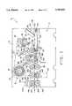
- FIG. 1is a plan view showing a lamina processing assembly of the present invention
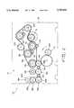
- FIG. 2is a gear drive train of the present invention corresponding to the lamina processing assembly of FIG. 1;
- FIG. 3ais a schematic perspective view of a supply roll of lamina suitable for use in the practice of the present invention
- FIG. 3bis a schematic perspective view of the supply roll of lamina of FIG. 3a after a laminate sheet has been cut from the roll;
- FIG. 4aside view of a pair of motor driven scissors used in the assembly of FIG. 1 with some parts shown in cross section;
- FIG. 4bis a top view of the scissors of FIG. 4a with some parts removed for clarity;
- FIG. 5is an end view of the scissors of FIG. 4a with parts removed to more clearly show the blade cam whose rotation opens and closes the scissors;
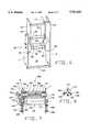
- FIG. 6is a perspective view showing the portion of the apparatus near the substrate entry zone of the lamina processing assembly of FIG. 1;
- FIG. 7is a side view of the heating apparatus used in the assembly of FIG. 1 with some parts shown in cross-section;
- FIG. 8is an end view of a portion of the heating apparatus of FIG. 7;
- FIG. 9is a perspective view of a laminated substrate prepared in accordance with the present invention.
- the apparatus 10comprises a support structure containing a front housing wall 11 (part of which is shown only in FIGS. 6 and 7) and a rear housing wall which for purposes of clarity is not shown in the drawings.
- Middle housing wall 12is disposed between the front housing wall and the rear housing wall and divides apparatus 10 into two main chambers.
- First chamber 13houses gear and sprocket drive train, generally designated 14 in FIG. 2.
- the second chamber 15houses the lamina processing assembly, generally designated 16 in FIG. 1.
- the lamina processing assembly 16includes a lamina supply member 20 on which a supply roll of heat bondable lamina 18 is rotatably stored.
- a lamina supply member 20on which a supply roll of heat bondable lamina 18 is rotatably stored.
- suitable lamina materialinclude "TBSN” lamina material available from TransilWrap and "H12-V” lamina material available from the Minnesota Mining and Manufacturing Company (3M).
- a lamina supply path 22extends from lamina supply member 20 to convergence zone 24.
- a sensor(not shown) of any suitable type may be disposed on lamina supply path 22 proximal to supply member 20 in order to detect when the supply of lamina 18 runs out.
- Lamina supply path 22passes between a first set of corresponding pinch rollers 26 and 28 and a second set of corresponding pinch rollers 30 and 32.
- First set of pinch rollers 26 and 28are disposed on the lamina supply path 22 at a position which is upstream relative to a cutter which is generally designated 42.
- Second set of pinch rollers 30 and 32are located on the lamina supply path 22 at a position which is downstream relative to the cutter 42.
- First set of pinch rollers 26 and 28are rotatably driven by clutch-driven gear and sprocket assembly 34 and idler gear 36, respectively.
- second set of pinch rollers 30 and 32are driven by clutch-driven gear and sprocket assembly 38 and idler gear 40, respectively.
- the rotation of the gear and sprocket assemblies 34 and 38 and idler gears 36 and 40causes pinch rollers 26, 30, 28 and 32 to correspondingly rotate. Rotation of these rollers, in turn, causes transport of lamina 13 along lamina supply path 22.
- wire guides(not shown for purpose of clarity) may be disposed along the top and bottom of the lamina supply path 22 to help guide lamina 18.
- cutter 42is a pair of motor-driven scissors.
- cutter/scissors 42is disposed on the lamina supply path 22 for cutting the supply of lamina 18 along cutting line 44 at a predetermined distance d, from leading edge 46 of lamina 18.
- Cutting of lamina 18 along cutting line 44provides heat bondable laminate sheet 48 having the same leading edge 46, but a newly provided trailing edge 50 at the cutting line 44.
- Cutting of lamina 18 along cutting line 44also provides the supply roll of lamina 18 with a successive leading edge 52.
- the remaining portion of lamina 18may then be cut along successive cutting line 55 to provide the next sheet of laminate corresponding to the portion of lamina 18 between successive leading edge 52 and successive cutting line 55. Additional sheets of laminate can be successively cut from the remaining portions of lamina 18 in a similar fashion until the supply of lamina runs out.
- a plurality of laminate sheetscan be cut from lamina supply 18 with substantially no waste between the trailing edge of each cut sheet and the successive leading edge of the next laminate sheet.
- the present inventiongenerates no wasted lamina, in sharp contrast to the prior art approaches which waste significant amounts of material.
- Scissors 42includes a top cutting blade 59 provided on a fixed top arm 60. Fixed top arm 60, in turn, is mounted to mounting block 56. A bottom cutting blade 61 is provided on a pivoting bottom arm 62. Pivoting bottom arm 62 includes a pivoting arm portion 63 which is pivotably coupled to blade pivot 64. Bottom cutting blade 61 can thus pivot about the blade pivot 64 from an open position as shown in the Figures to a closed position at which the bottom cutting blade 61 cuttingly engages top cutting blade 59. When bottom cutting blade 61 is in the open position, lamina supply path 22 passes between top cutting blade 59 and bottom cutting blade 61. When the supply of lamina 18 is conveyed along lamina supply path 22 between blades 60 and 62, bottom cutting blade 61 closes and then opens to cut the lamina with a scissor type action.
- lamina spring 65is disposed on mounting block 56 to help bias the lamina 18 downward away from the fixed cutting blade 59 as the leading edge of the lamina 18 is guided through scissors 42. In the absence of lamina spring 65, the leading edge of lamina 18 may tend to jam against the upstream side of the top cutting blade 59 and/or the fixed top arm 60.
- Lamina spring 65is desirably fabricated from a resiliently flexible material such as a metal, metal alloy, thermoplastic or thermoset polymer, and the like. Specific examples of suitable materials would include polycarbonate, polyurethane, polyester, copper, bronze, stainless steel, and aluminum or an aluminum alloy.
- Fingers 66project backwards from mounting block 56 and fit into corresponding grooves (not shown) in roller 26. Fingers 66 help prevent lamina 18 from wrapping upward around roller 26 as the leading edge of lamina 18 is guided past roller 26.
- scissors 42is motor-driven.
- clutch-controlled sprocket assembly 72rotatably drives blade cam shaft 70 which, in turn, rotatably drives blade cam 68.
- Blade cam shaft 70is rotatably journalled upon bearings 86 and 87 which are provided in apertures of auxiliary housing wall 58 and middle housing wall 12.
- Blade cam 68includes ball track 74 for retaining cam follower 76.
- Finger 78provided at the end of pivoting bottom arm 62, couples pivoting bottom arm 62 to cam follower 76.
- Rotatable blade cam 68is eccentrically mounted on blade camshaft 70 such that rotation of blade cam 68 causes the pivoting bottom cutting blade 62 to pivotally open and close about blade pivot 64.
- scissors 42is oriented such that the cutting action of the scissors is substantially perpendicular to the lamina supply path 22.
- one revolution of blade cam 68closes and then opens bottom cutting blade 61.
- shaft 70is provided with shaft rotary location pin 83.
- pin 83contacts shaft location switch 82.
- pin 83may be positioned so that pin 83 is in contact, or just past the point of contact if desired, with switch 83.
- Clutch controlled sprocket 72is engaged to rotate shaft 70.
- scissors 42will have closed and opened to cut a laminate sheet from lamina 18.
- Pin 83contacts switch 82 again after one revolution of shaft 70 as well, and sprocket 72 is then disengaged.
- the pivoting cutting blade 61is disposed on the lamina supply path on the upstream side of scissors 42 relative to fixed cutting blade 59.
- successive leading edges of cut lamina 18do not tend to stick to the scissors 42 after cutting when the pivoting blade 61 is located on the upstream side of scissors 42, because the opening action of the pivoting blade 61 tends to release the successive leading edges.
- apparatus 10includes sensor 88 provided on mounting block 89 along supply path 22 between scissors 42 and convergence zone 24 in order to detect when a predetermined reference on lamina 18 is at a predetermined distance from the cutting line of scissors 42.
- a referencemay be any suitable feature of lamina 18 which can be detected by the sensor. Examples of such features include the leading edge of the lamina 18 as well as markings, such as authentication images, provided on the surface of lamina 18.
- sensor 88is disposed at a predetermined distance from the cutting line of scissors 42 to detect each successive leading edge of the supply of lamina 18 as lamina 18 is conveyed along path 22.
- laminate sheetsare used to laminate many kinds of ISO Standard CR-80 type cards. All such cards, within specification tolerances, are characterized by a width of 2 1/8 inches (5.40 cm) and a length of 3 3/8 inches (8.57 cm).
- lamina supply 18may bear a plurality of authentication images, such as holographic images or the like, which must be precisely positioned on each corresponding substrate.
- authentication imagessuch as holographic images or the like
- drivers licenses of some states and countriesinclude a holographic authentication image precisely positioned over portions of the photographic image and textual information included on such licenses.
- alternative embodiments of the inventionmay include sensor 90 disposed at a position on lamina supply path 22 suitable for detecting when the authentication reference, rather than the leading edge, of lamina 18 is at a predetermined distance from the cutting line of scissors 42. When sensor 90 detects each such authentication image, scissors 42 may then be actuated to cut the lamina 18. As this process is repeated, all of the resultant laminated sheets will have been cut to a substantially identical length in which the authentication image is precisely positioned on each such sheet.
- Sensor 90may be mounted on mounting block 91.
- sensors 88 and 90 used in apparatus 10may be any type of sensor known in the art which would be suitable for detecting the predefined reference of the lamina.
- a type of sensor found to be suitable in the practice of the present invention for this purposeis a standard reflective type LED sensor.
- Such sensorsare reliable and accurate. Further, as known in the art, the reliability and accuracy of such sensors can be even further improved by placing a dull, black, nonreflective plate (not shown), or another nonreflective type of member, in opposition to such sensors in order reduce the tendency of such sensors to generate false detection signals.
- apparatus 10includes a substrate supply path 92 extending from substrate entry zone 94 to convergence zone 24.
- a substrate guiding devicegenerally designated 96, is provided on substrate supply path 92 near substrate entry zone 94.
- Substrate guiding device 96includes bevelled entry blocks 98 and 99 provided on each side of the substrate supply path 92. As seen best in FIG. 6, bevelled entry block 98 is mounted on front housing wall 11, and bevelled entry block 99 is mounted on middle housing wall 12. Above bevelled entry blocks 98 and 99, deflection plate 114 is pivotably disposed between auxiliary plates 116 and 117 on axle 118. Deflection plate 114 biases the substrates downward onto substrate supply path 92.
- a plurality of structural members, such as structural members 120, 121, 122 and 123,are provided in order to impart strength and rigidity to apparatus 10.
- First conveyor roller 102is rotatably supported between bevelled entry blocks 98 and 99. Further along the substrate supply path 92, path 92 passes between pinch roller 108 and second conveyor roller 104.
- a pair of endless loop drivers 106 and 107are mounted around first conveyor roller 102 and second conveyor roller 104. Pinch roller 108 and second conveyor roller 104 are rotatably driven by clutch-controlled gear and sprocket assembly 110 and idler gear 112, respectively.
- Rotation of second conveyor roller 104causes rotation of endless loop drivers 106 and 107 about first conveyor roller 102 and second conveyor roller 104.
- Such rotation of endless loop drivers 106 and 107causes transport of a substrate along that portion of substrate supply path 92 corresponding to endless loop drivers 106 and 107.
- Support member 124is provided for supporting the substrate along another portion of path 92 after the substrate is conveyed past pinch roller 108 and second conveyor roller 104.
- Support member 124has a flat upper surface 126 providing a pathway which is slidably engaged by the substrate as the substrate is conveyed across support member 124.
- Support member 124further includes a pair of sidewall members, one of which is shown as sidewall 128, to help constrain the substrate in position on upper surface 126.
- Upper surface 126includes an entry bevel 130, and the sidewall members include entry bevels such as bevel 132, in order to ease entry of the substrate onto support member 124.
- Sensor 134is provided on the substrate supply path 92 and is mounted in position by fastening sensor flange 136 to the underside surface 137 of support member 124 with a suitable fastener, such as screw 138. Sensor 134 detects when a reference on the substrate is at a predetermined distance from the convergence zone 24. As was the case with lamina 18, the substrate reference may be any suitable feature of the substrate which can be detected by sensor 134. Examples of such features include the leading edge of the substrate as well as any markings, such as images or textual information, which may be provided on the substrate.
- the position of sensor 134is coordinated with the position of sensor 88 so that the substrate and the laminate sheet, after the sheet has been cut from lamina 18, arrive at convergence zone 24 in a manner which allows the substrate and the laminate sheet to be brought together in proper registration.
- the cut sheet of laminate and the substratedesirably arrive at the convergence zone 24 at substantially the same time while being conveyed at substantially the same speed along their respective paths.
- the distance between convergence zone 24 and sensor 134is substantially the same as the distance between convergence zone 24 and sensor 88.
- sensor 134may be any sensor known in the art which would be suitable for detecting the predefined reference of the substrate.
- a type of sensor found to be suitable in the practice of the present inventionis a standard reflective type LED sensor.
- the performance of such a sensorcan be improved by placing a dull, nonreflective, black plate (not shown), or another non-reflective type of member, in opposition to said sensor in order to reduce the tendency of such sensor to generate false detection signals. Due to the positioning of sensors 88 and 134, a single plate may be disposed between the two sensors in order to reduce such false detection incidents.
- Convergence zone 24the laminate sheet and substrate are registrably brought into contact to provide a sheet-bearing substrate.
- Convergence zone 24, as shown,comprises a pair of pinch rollers 140 and 142 which are rotatably driven by idler gear 146 and clutch-driven gear and sprocket assembly 144, respectively.
- Lamina supply path 22 and substrate supply path 92converge between pinch rollers 140 and 142 at convergence point 143 to form processing path 148, which extends from such point of convergence 143 to exit zone 150.
- Heating apparatus 152is disposed on processing path 148 for bonding the laminate sheet to a corresponding substrate.
- Heating apparatus 152includes heated roller assembly 154 and corresponding pinch roller 156.
- Heated roller assembly 154 and pinch roller 156are disposed on processing path 148 such that the laminate-bearing substrate is conveyed between heated roller assembly 154 and pinch roller 156 as the laminate bearing substrate is conveyed along the processing path.
- Pinch roller 156is rotatably mounted on adjustment plate 162. Movement of adjustment plate 162 allows the distance between pinch roller 156 and heated roller assembly 154 to be changed in order to accommodate different thickness of substrates and laminates.
- Heated roller assembly 154 and pinch roller 156are rotatably driven by gear 158 and gear 160, respectively. Together, heated roller assembly 154 and pinch roller press the laminate sheet and the substrate together as the heater applies heat for bonding.
- heated roller assembly 154includes a non-rotatable heater core 164 having a heated portion 166.
- Rotatable outer shell 168is disposed on non-rotatable heater core 164 such that the non-rotatable heater core 164 heats rotatable outer shell 168.
- Rotatable outer shell 168heatably bonds the laminate sheet to the substrate.
- Rotatable outer shell 168is coupled to non-rotatable heater core 164 by any suitable bearing means which allows rotatable outer shell 168 to rotate freely about the non-rotatable heater core 164. As shown in the embodiment in FIG.
- rotatable outer shell 168is coupled to non-rotatable heater core 164 by inner pair of bearings 170 and 171 and outer pair of bearings including bearing 172 and the hub of gear 158 which serves as the other outer bearing.
- Gear 158couples the heated roller assembly 154 to pinch roller 156.
- inner bearings 170 and 171are non-rotatably coupled to the non-rotatable heater core 164. Additionally, outer bearing 172 and the hub of gear 158 are non-rotatably coupled to rotatable outer shell 168. Outer bearing 172 and the hub of gear 158, however, are fully rotatable about inner bearings 170 and 171. In order to reduce friction between the two sets of bearings, it is desirable that at least one set of such bearings comprises a self lubricating resin which is preferably polytetrafluorethylene. Polytetrafluorethylene is more commonly referred to by its trade designation "Teflon". For example, inner bearing 170 and the hub of gear 158 may be fabricated from Teflon brand resin and outer bearing 172 and gear 158 may be fabricated from stainless steel.
- Heated roller assembly 154is mounted between middle housing wall 12 and front housing wall 11.
- Middle housing wall 12 and front housing wall 11desirably include apertures for receiving corresponding ends of non-rotatable heater core 164.
- Flange 174is used to secure heated roller assembly 154 to the middle housing wall 12 using any suitable fastener, such as screws 176.
- Pinch roller 156includes a roller body 177 and an axle 178.
- Axle 178is rotatably received in corresponding apertures provided in middle housing wall 12 and front housing wall 11.
- Pinch roller 156is secured in place by auxiliary plates 186 and 187 which are fastened to middle housing wall 12 and front housing wall 11 using any suitable fastener, such as screws 188.
- Pinch roller 156is rotatably driven by gear 160.
- Gear 180 of pinch roller 156in turn, rotatably drives gear 158 of heated roller assembly 154.
- Non-rotatable heater core 164Energy for heating heated portion 166 of non-rotatable heater core 164 is provided to heated roller assembly 154 through heater wires 190.
- Thermocouple wires 192are used to monitor the temperature of non-rotatable heater core 164. In order to maintain the non-rotatable heater core 164 at a desired temperature, the energy supply to heater wires 190 can be increased or decreased, as needed.
- the process of using heat to bond the laminate sheet to the substratecan cause the resultant laminated substrate to bend, or "cargo" as such bending is sometimes called.
- the face of the laminated substrate bearing the laminate sheetcan be characterized by a convex or concave bend. It is desirable, therefore, to apply a reverse bend to the laminated substrate in order to remove such convex or concave bend.
- card straightener 194is provided on processing path 148 for applying a reverse bend to the laminated substrate after the laminated substrate leaves heating apparatus 152.
- card straightener 194is an assembly comprising a first pinch roller 196 having a center of rotation 198 and a second pinch roller 200 having a center of rotation 202.
- Pinch rollers 196 and 200are rotatably mounted on adjustment plate 204 and are disposed on processing path 148 such that processing path 148 passes between rollers 196 and 200.
- a line extending from the center of rotation 198 to the center of rotation 202defines a main axis of the card straightener 194.
- Adjustment plate 204is pivotable about a pivot point so that the main axis of the card straightener 194 can be pivoted as well.
- center of rotation 202 or 198, and more preferably center of rotation 202serves as the pivot point for adjustment plate 204.
- Pinch rollers 196 and 200are rotatably driven by gears 206 and 208, respectively.
- card straightener 194can be adjusted to provide a reverse convex or concave bend as desired.
- center of rotation 202serves as the pivot point for adjustment plate 204
- pivoting of adjustment plate 204 toward the exit zone 150causes the main axis of the card straightener 194 to pivot toward exit zone 150 as well.
- Such an orientation of the axisapplies a reverse bend to the laminated substrate in which the leading edge of the laminated substrate is flexed downward. This is a useful approach for applying a reverse bend when the laminated substrate emerges from heating apparatus 142 in a condition in which the laminate sheet bearing side of the laminated substrate has a concave bend.
- pivoting of the adjustment plate 204 toward the heating apparatus 152causes the main axis to pivot toward heating apparatus 152 as well.
- Such orientation of the main axisapplies a reverse bend to the laminated substrate in which the leading edge of the laminated substrate is flexed upward by card straightener 194. This is a useful approach when the laminated substrate emerges from the heating apparatus 152 in a condition in which the laminate bearing side of the laminated substrate has a convex bend.
- Gear and sprocket drive train 14will now be more fully described with particular reference to FIG. 2.
- Power from a motoris transferred to drive train 14 through motor driven gear 210.
- motor driven gear 210rotates counter-clockwise and is coupled to the remainder of drive train 14 through large idler gear 212.
- Rotation of idler gear 212rotatably drives gear 146.
- Rotational power of gear 146is subsequently transferred to gear 160 and gear 208 through idler gears 214 and 215, respectively.
- Idler gears 214 and 215not only transfer power to gears 160 and 208, but the use of idler gears 214 and 215 also ensures that gears 160 and 208 are rotating in the proper direction. Gears 160 and 208 rotatably drive gears 158 and 206, respectively.
- Gear 146also transfers rotational power to gear and sprocket assembly 144.
- Gear and sprocket assembly 144is coupled, in turn, to clutch driven gear and sprocket assemblies 34, 38, and 110, as well as clutch driven sprocket 72, by timing belt 216.
- Clutch driven sprocket assemblies 34, 38, and 110in turn, rotatably drive corresponding gears 36, 40, and 112.
- Drive train 14further includes idler gear 218 which is disposed in drive train 14 in a manner to maintain engagement between timing belt 216 and clutch driven gear and sprocket assemblies 34 and 38.
- Adjustable belt tensioning sprocket 220is also provided and can be moved to adjust the tension of timing belt 216, as desired.
- timing belt 216causes gear and sprocket assemblies 34, 38, 110, and 144 all to rotate at substantially the same rotational speed so that the substrate and the laminate sheet are conveyed along their respective paths at substantially the same speed.
- the scissor sprocket 72need not rotate at the same speed as such assemblies, and, in the embodiment shown, sprocket 72 is configured to rotate at a quicker speed than such assemblies.
- Clutch driven gear and sprocket assemblies 34 and 38are engaged to cause rotation of rollers 26, 28, 30, and 32. Rotation of these rollers causes the transport of lamina 18 along lamina supply path 22.
- clutch driven gear and sprocket assemblies 34 and 38are disengaged and transport of lamina 18 stops.
- Scissors 42is then actuated to cut through lamina 18 along a cutting line to provide a first cut sheet of heat bondable laminate.
- clutch driven sprocket and gear assembly 110is engaged which, in turn, actuates rollers 108, 104, and 102 to convey a substrate along the substrate supply path 92.
- Engaging sprocket and gear assembly 110 only after the lamina 18 is cuthelps make sure that a substrate is not fed into the apparatus 10 too soon.
- the substrateenters apparatus 10 through substrate entry zone 94.
- Substratemay be fed into apparatus 10 in any desired manner.
- the substratemay be hand fed into apparatus 10 or alternatively, may be automatically fed into apparatus 10 directly from a suitable device, such as a printer.
- deflection plate 114biases the substrate against endless loop drivers 106 and 107.
- clutch driven gear and sprocket assembly 110is engaged to rotatably drive pinch roller 108, first conveyor roller 102, second conveyor roller 104, and endless loop drivers 106 and 107.
- rollers 140, 142, 154, 156, 196 and 200are rotatably driven by corresponding components of gear drive train 14, and rotation of these rollers conveys the substrate and laminate along the processing path 148.
- a laminate bearing substratethen emerges from between pinch rollers 140 and 142 and is next conveyed between heated roller assembly 154 and pinch roller 156.
- heat from heated roller 154activates the adhesive on the laminate sheet in order to bond the laminate sheet to the substrate.
- the laminated products producedmay tend to be characterized either by a convex or concave bend. If this happens, card straightener 194 may be adjusted to apply an appropriate reverse bend to the laminated product before the laminated product leaves apparatus 10 through exit zone 150. Subsequent laminated products are formed from lamina 18 and additional substrates by repeating these operations.
- apparatusmay include a microprocessor which controls such functions.
- apparatus 10may include convenience features which convey information about the apparatus 10 to a user.
- apparatus 10may be provided with lights or instruments which tell the user information such as the status of the lamina supply, the status of the clutch-controlled elements, heater temperature, orientation of the card straightener axis, number of laminate sheets cut by the scissors 42, and the like.
- FIG. 9shows a laminated substrate 300 prepared in accordance with the present invention.
- Laminated substrate 300includes card-shaped substrate 301 having face 302.
- Substrate 301may be made from a variety of materials such as, for example, paper, cardboard, plastic, metal, or the like.
- Face 302may include information such as photographs, other graphics, text, data, or the like.
- Laminate sheet 304is bonded to face 302.
- the bottom face (not shown) of substrate 301may also include information and have a second laminate sheet bonded to it as well.
- Corners 306are angular, not rounded, and are most typically substantially square. Square corners result when scissors 42 of FIG. 1 is used to cut lamina 18 along a cutting line which is substantially perpendicular to the sides of lamina 18.
- laminate sheet 304is slightly narrower and slightly shorter than the face 302 in order to ease registration of the laminate sheet 304 onto face 302.
- laminate sheet 304which is 1/8" (0.32 cm) shorter and 1/8" (0.32 cm) narrower than substrate 301 has been found to be suitable in the practice of the present invention.
- laminated substrate 300The characteristics of laminated substrate 300 are distinguishable over laminated substrates made using the prior art techniques described above. For example, when using the "decal” approach, the entire face 302 is covered by laminate material. When using the "die-cut” approach, the laminate sheet corners have been rounded, not square.
Landscapes
- Engineering & Computer Science (AREA)
- Life Sciences & Earth Sciences (AREA)
- Forests & Forestry (AREA)
- Mechanical Engineering (AREA)
- Quality & Reliability (AREA)
- Lining Or Joining Of Plastics Or The Like (AREA)
Abstract
Description
Claims (12)
Priority Applications (3)
| Application Number | Priority Date | Filing Date | Title |
|---|---|---|---|
| US08/630,681US5783024A (en) | 1996-04-12 | 1996-04-12 | Apparatus for applying heat bondable lamina to a substrate |
| US08/993,270US6007660A (en) | 1996-04-12 | 1997-12-18 | Method for applying heat bondable lamina to a substrate |
| US09/075,088US6159327A (en) | 1996-04-12 | 1998-05-08 | Apparatus and method for applying heat bondable lamina to a substrate |
Applications Claiming Priority (1)
| Application Number | Priority Date | Filing Date | Title |
|---|---|---|---|
| US08/630,681US5783024A (en) | 1996-04-12 | 1996-04-12 | Apparatus for applying heat bondable lamina to a substrate |
Related Child Applications (1)
| Application Number | Title | Priority Date | Filing Date |
|---|---|---|---|
| US08/993,270DivisionUS6007660A (en) | 1996-04-12 | 1997-12-18 | Method for applying heat bondable lamina to a substrate |
Publications (1)
| Publication Number | Publication Date |
|---|---|
| US5783024Atrue US5783024A (en) | 1998-07-21 |
Family
ID=24528159
Family Applications (2)
| Application Number | Title | Priority Date | Filing Date |
|---|---|---|---|
| US08/630,681Expired - LifetimeUS5783024A (en) | 1996-04-12 | 1996-04-12 | Apparatus for applying heat bondable lamina to a substrate |
| US08/993,270Expired - LifetimeUS6007660A (en) | 1996-04-12 | 1997-12-18 | Method for applying heat bondable lamina to a substrate |
Family Applications After (1)
| Application Number | Title | Priority Date | Filing Date |
|---|---|---|---|
| US08/993,270Expired - LifetimeUS6007660A (en) | 1996-04-12 | 1997-12-18 | Method for applying heat bondable lamina to a substrate |
Country Status (1)
| Country | Link |
|---|---|
| US (2) | US5783024A (en) |
Cited By (84)
| Publication number | Priority date | Publication date | Assignee | Title |
|---|---|---|---|---|
| US6003581A (en)* | 1996-03-04 | 1999-12-21 | Nippon Petrochemicals Company, Limited | Apparatus for laminating webs |
| US6007660A (en)* | 1996-04-12 | 1999-12-28 | Polaroid Corporation | Method for applying heat bondable lamina to a substrate |
| US6012641A (en)* | 1995-12-06 | 2000-01-11 | Watada Printing Co., Ltd. | Laminated stretched and unstretched polyester card for IC card |
| WO2000027634A1 (en)* | 1998-11-06 | 2000-05-18 | Fargo Electronics, Inc. | Identification card printer and laminator |
| US6095220A (en)* | 1997-06-23 | 2000-08-01 | Nisca Corporation | Overcoat fixing device |
| US6159327A (en)* | 1996-04-12 | 2000-12-12 | Polaroid Corporation | Apparatus and method for applying heat bondable lamina to a substrate |
| US6244319B1 (en) | 1998-09-25 | 2001-06-12 | Atlantek, Inc. | Card laminating apparatus |
| US6283188B1 (en) | 1998-09-25 | 2001-09-04 | Atlantek, Inc. | Card laminating apparatus |
| WO2001033163A3 (en)* | 1999-10-29 | 2001-11-22 | Fargo Electronics Inc | Alignment sensor and control system for laminate film and card |
| WO2002028621A3 (en)* | 2000-10-03 | 2002-06-20 | Fargo Electronics Inc | Overlaminate patch having improved security and method for its manufacture |
| US20020139485A1 (en)* | 2001-03-30 | 2002-10-03 | Naotaka Sasaki | Lamination system |
| JP2002292738A (en)* | 2001-03-29 | 2002-10-09 | Japan Servo Co Ltd | Lamination apparatus |
| JP2002301765A (en)* | 2001-04-04 | 2002-10-15 | Japan Servo Co Ltd | Laminator |
| JP2002307553A (en)* | 2001-04-06 | 2002-10-23 | Japan Servo Co Ltd | Lamination apparatus |
| US20020166635A1 (en)* | 2001-05-14 | 2002-11-14 | Naotaka Sasaki | Lamination system |
| JP2002331582A (en)* | 2001-05-08 | 2002-11-19 | Japan Servo Co Ltd | Laminator device |
| US6484780B2 (en)* | 2001-03-21 | 2002-11-26 | Card Technology Corporation | Card laminator and method of card lamination |
| US20030090712A1 (en)* | 1999-07-14 | 2003-05-15 | Lenz Gary A. | Identification card printer with client/server |
| WO2003056507A1 (en) | 2001-12-24 | 2003-07-10 | Digimarc Id Systems, Llc | Systems, compositions, and methods for full color laser engraving of id documents |
| US20030178149A1 (en)* | 2002-03-19 | 2003-09-25 | Naotaka Sasaki | Wasteless type lamination system |
| US20030178495A1 (en)* | 2001-12-24 | 2003-09-25 | Robert Jones | Contact smart cards having a document core, contactless smart cards including multi-layered structure, pet-based identification document, and methods of making same |
| US20030188615A1 (en)* | 2002-04-03 | 2003-10-09 | 3M Innovative Properties Company | Angled product transfer conveyor |
| US20030188831A1 (en)* | 2002-04-04 | 2003-10-09 | Naotaka Sasaki | Lamination system |
| US20030191021A1 (en)* | 2002-04-03 | 2003-10-09 | 3M Innovative Properties Company | Lamination apparatus and methods |
| US20030188418A1 (en)* | 2002-04-03 | 2003-10-09 | 3M Innovative Properties Company | Apparatus and method for separating a fuel cell assembly from a bonding fixture |
| US20030188616A1 (en)* | 2002-04-03 | 2003-10-09 | Behymer Lance E. | Compliant cutting die apparatus for cutting fuel cell material layers |
| US20030211296A1 (en)* | 2002-05-10 | 2003-11-13 | Robert Jones | Identification card printed with jet inks and systems and methods of making same |
| US20030216826A1 (en)* | 2002-03-01 | 2003-11-20 | Fargo Electronics, Inc. | Identification card manufacturing security |
| US20030230379A1 (en)* | 2002-06-14 | 2003-12-18 | Roubik Marc L. | Two-sided lamination method for controlling curl |
| EP1247643A3 (en)* | 2001-04-06 | 2004-01-21 | ZIH Corporation | Carrier-less patch production including cassette and separation process |
| US6698487B2 (en) | 2000-11-15 | 2004-03-02 | Xyron, Inc. | Master processing apparatus |
| US20040069401A1 (en)* | 2002-07-11 | 2004-04-15 | Wurdell Grant H. | Wasteless laminator |
| US6733912B2 (en) | 2002-04-03 | 2004-05-11 | 3M Innovative Properties Company | Fixture pallet apparatus for automated assembly of fuel cell material layers |
| US6736179B2 (en) | 2001-03-29 | 2004-05-18 | Japan Servo Co., Ltd. | Lamination system |
| US6740131B2 (en) | 2002-04-03 | 2004-05-25 | 3M Innovative Properties Company | Apparatus for automatically fabricating fuel cell |
| US20040101340A1 (en)* | 2001-03-05 | 2004-05-27 | Fargo Electronics, Inc. | Ink-receptive card substrate |
| US20040108052A1 (en)* | 2002-12-05 | 2004-06-10 | Haga Matthew Howard | Apparatus and method for applying a removable cover to a ticket substrate |
| US6756146B2 (en) | 2002-04-03 | 2004-06-29 | 3M Innovative Properties Company | Apparatus and method for automatically stacking fuel cell material layers |
| US6780276B2 (en) | 2002-04-03 | 2004-08-24 | 3M Innovative Properties Company | Gap adjuster for laminating rolls |
| US20040188023A1 (en)* | 2003-03-27 | 2004-09-30 | Naotaka Sasaki | Double-side lamination system |
| US20040224103A1 (en)* | 2001-03-05 | 2004-11-11 | Fargo Electronics, Inc. | Identification cards, protective coatings, films, and methods for forming the same |
| US20040241525A1 (en)* | 2003-05-28 | 2004-12-02 | 3M Innovative Properties Company | Roll-good fuel cell fabrication processes, equipment, and articles produced from same |
| US20050039851A1 (en)* | 2002-04-03 | 2005-02-24 | 3M Innovative Properties Company | Method and apparatus for peeling a thin film from a liner |
| US20050039859A1 (en)* | 2003-08-22 | 2005-02-24 | Kenji Sugaya | Lamination system |
| US20050060239A1 (en)* | 2003-09-11 | 2005-03-17 | Fargo Electronics, Inc. | Identification card manufacturing system supply ordering and diagnostic report |
| US20050084693A1 (en)* | 2003-10-21 | 2005-04-21 | Brian Labrec | Document laminate formed from different polyester materials |
| US20050109450A1 (en)* | 2003-11-25 | 2005-05-26 | Fargo Electronics, Inc. | Laminate feeding in a card manufacturing device |
| US20050194102A1 (en)* | 2002-04-03 | 2005-09-08 | 3M Innovative Properties Company | Apparatus and method for singulating porous fuel cell layers using adhesive tape pick head |
| US20050257253A1 (en)* | 2004-05-03 | 2005-11-17 | Fargo Electronics, Inc | Managed credential issuance |
| US20060027667A1 (en)* | 2000-12-22 | 2006-02-09 | Jones Robert L | Identification document with integrated circuit and antenna in a layered document structure |
| US20060123471A1 (en)* | 2003-02-21 | 2006-06-08 | Fargo Electronics, Inc. | Credential production using a secured consumable supply |
| US20060138243A1 (en)* | 2004-12-28 | 2006-06-29 | Daoshen Bi | ID document structure with pattern coating providing variable security features |
| EP1700690A1 (en)* | 2005-03-07 | 2006-09-13 | GMP Co., Ltd. | Laminator with small film roll |
| US20060222830A1 (en)* | 2005-03-30 | 2006-10-05 | Daoshen Bi | Image destruct feature used with image receiving layers in secure documents |
| US20060228530A1 (en)* | 2005-03-30 | 2006-10-12 | Daoshen Bi | Image destruct feature used with image receiving layers in secure documents |
| US20070102920A1 (en)* | 2005-07-26 | 2007-05-10 | Daoshen Bi | Forensic feature for secure documents |
| US20070274755A1 (en)* | 2003-09-12 | 2007-11-29 | Fargo Electronics, Inc. | Reverse-image identification card printer |
| WO2008028158A2 (en) | 2006-09-01 | 2008-03-06 | Digimarc Corporation | Laser marking of pigment layers on documents |
| US20080106002A1 (en)* | 2006-11-06 | 2008-05-08 | Josef Feldman | Laminated identification document |
| US7399131B2 (en) | 2001-03-05 | 2008-07-15 | Fargo Electronics, Inc. | Method and Device for forming an ink-receptive card substrate |
| US7661600B2 (en) | 2001-12-24 | 2010-02-16 | L-1 Identify Solutions | Laser etched security features for identification documents and methods of making same |
| US7694887B2 (en) | 2001-12-24 | 2010-04-13 | L-1 Secure Credentialing, Inc. | Optically variable personalized indicia for identification documents |
| US7712673B2 (en) | 2002-12-18 | 2010-05-11 | L-L Secure Credentialing, Inc. | Identification document with three dimensional image of bearer |
| US7728048B2 (en) | 2002-12-20 | 2010-06-01 | L-1 Secure Credentialing, Inc. | Increasing thermal conductivity of host polymer used with laser engraving methods and compositions |
| US7744002B2 (en) | 2004-03-11 | 2010-06-29 | L-1 Secure Credentialing, Inc. | Tamper evident adhesive and identification document including same |
| US7744001B2 (en) | 2001-12-18 | 2010-06-29 | L-1 Secure Credentialing, Inc. | Multiple image security features for identification documents and methods of making same |
| US7789311B2 (en) | 2003-04-16 | 2010-09-07 | L-1 Secure Credentialing, Inc. | Three dimensional data storage |
| US7798413B2 (en) | 2001-12-24 | 2010-09-21 | L-1 Secure Credentialing, Inc. | Covert variable information on ID documents and methods of making same |
| US7804982B2 (en) | 2002-11-26 | 2010-09-28 | L-1 Secure Credentialing, Inc. | Systems and methods for managing and detecting fraud in image databases used with identification documents |
| US7815124B2 (en) | 2002-04-09 | 2010-10-19 | L-1 Secure Credentialing, Inc. | Image processing techniques for printing identification cards and documents |
| US7824029B2 (en) | 2002-05-10 | 2010-11-02 | L-1 Secure Credentialing, Inc. | Identification card printer-assembler for over the counter card issuing |
| US8099187B2 (en) | 2005-08-18 | 2012-01-17 | Hid Global Corporation | Securely processing and tracking consumable supplies and consumable material |
| US20120132339A1 (en)* | 2010-11-29 | 2012-05-31 | Waytek Corporation | System and Method for Making Laminated Sheets |
| US8730283B2 (en) | 2009-09-18 | 2014-05-20 | Assa Abloy Ab | Credential substrate feeding in a credential processing device |
| JP2014101220A (en)* | 2012-11-22 | 2014-06-05 | Kyocera Document Solutions Inc | Curl correction device and image formation apparatus including the same |
| US8956490B1 (en) | 2007-06-25 | 2015-02-17 | Assa Abloy Ab | Identification card substrate surface protection using a laminated coating |
| US20150210105A1 (en)* | 2012-09-05 | 2015-07-30 | Gemalto Sa | Card with marbled visual effect and associated manufacturing process |
| EP1768507A4 (en)* | 2004-05-21 | 2015-09-09 | Illinois Tool Works | METHOD FOR PRODUCING A LAMINATE FOIL AND PRODUCT THEREOF PRODUCED |
| ITUB20152253A1 (en)* | 2015-07-16 | 2017-01-16 | S E M Servizi Editoriali Milano S P A | EQUIPMENT AND AUTOMATIC PLASTIFICATION METHOD |
| CN108385078A (en)* | 2018-02-26 | 2018-08-10 | 深圳市华星光电技术有限公司 | Flexible base board and preparation method thereof |
| US10086638B2 (en) | 2014-10-07 | 2018-10-02 | Morphotrust Usa, Llc | System and method for laser writing |
| US10095924B1 (en) | 2015-12-31 | 2018-10-09 | Morphotrust Usa, Llc | Document authentication |
| US10828877B2 (en) | 2016-03-09 | 2020-11-10 | Assa Abloy Ab | Patch lamination device and method |
| CN116710288A (en)* | 2021-02-25 | 2023-09-05 | 大日本印刷株式会社 | Printer, printer control method, printed matter manufacturing method |
Families Citing this family (10)
| Publication number | Priority date | Publication date | Assignee | Title |
|---|---|---|---|---|
| US6986824B2 (en)* | 1998-08-04 | 2006-01-17 | Canon Kabushiki Kaisha | Process and apparatus for forming images |
| EP1282510B1 (en)* | 2000-05-18 | 2004-09-22 | Steinemann Technology AG | Method and device for cutting a laminate |
| ATE380634T1 (en) | 2000-11-01 | 2007-12-15 | Adalis Corp | FEED SYSTEM FOR WEB-SHAPED MATERIAL AND DEVICE FOR APPLYING WEB-SHAPED MATERIAL |
| US6893528B2 (en)* | 2000-11-01 | 2005-05-17 | Adalis Corporation | Web material advance system for web material applicator |
| US20030091779A1 (en)* | 2001-11-13 | 2003-05-15 | Brewster Frederick H. | Cutting edge for dispenser cartons |
| US7172666B2 (en)* | 2002-12-17 | 2007-02-06 | Groves Matthew E | Web material application methods and systems |
| WO2007140289A2 (en)* | 2006-05-25 | 2007-12-06 | The Meyers Printing Companies, Inc. | Promotional assembly |
| US7617986B2 (en)* | 2007-01-10 | 2009-11-17 | Datacard Corporation | Laminate security feature |
| WO2010151166A1 (en)* | 2009-06-24 | 2010-12-29 | Lebed Aleksandr Nazarovich | Lottery ticket |
| CN111469544A (en)* | 2020-05-11 | 2020-07-31 | 万睿轩 | Paper printing protection tectorial membrane device |
Citations (23)
| Publication number | Priority date | Publication date | Assignee | Title |
|---|---|---|---|---|
| US3140214A (en)* | 1959-04-07 | 1964-07-07 | New Jersey Machine Corp | Labeling machines |
| US3455768A (en)* | 1962-03-26 | 1969-07-15 | Windmoeller & Hoelscher | Apparatus for welding flat blanks of plastic or plastic-coated material onto plastic articles |
| US3536550A (en)* | 1966-01-28 | 1970-10-27 | New Jersey Machine Corp | Method of and apparatus for printing and feeding labels in a continuous web,and for verifying and cutting individual labels therefrom for application to articles |
| US3565724A (en)* | 1967-07-31 | 1971-02-23 | Nishimura Seisakusho Co | Automatic labelling machine |
| US3625801A (en)* | 1969-12-03 | 1971-12-07 | Kellog Co | Lid applicator |
| US3658629A (en)* | 1970-02-27 | 1972-04-25 | Ibm | Photopolymer resist sheet laminator |
| US3713948A (en)* | 1970-12-14 | 1973-01-30 | Xerox Corp | Labeling machine |
| US4181558A (en)* | 1974-07-09 | 1980-01-01 | Rolf Neubronner | Method and device for the tape-sealing of panels of paper, cardboard, plastic, or wood, and adhesive tape therefor |
| US4272311A (en)* | 1979-05-17 | 1981-06-09 | Angelo Joseph J D | Method and apparatus for automatically labelling containers |
| US4448631A (en)* | 1983-02-12 | 1984-05-15 | Banctec, Inc. | Encodable strip attachment apparatus |
| US4491492A (en)* | 1982-10-28 | 1985-01-01 | At&T Technologies, Inc. | Methods of and apparatus for applying a sheet to a rigid board |
| US4517042A (en)* | 1982-09-30 | 1985-05-14 | D&K Custom Machine Design, Inc. | Method and apparatus for decurling laminated stock |
| US4717441A (en)* | 1986-07-14 | 1988-01-05 | Somar Corporation | Laminator |
| US4832783A (en)* | 1985-07-01 | 1989-05-23 | Dennison Manufacturing Company | Apparatus for rotational decoration of articles |
| US4925521A (en)* | 1988-07-01 | 1990-05-15 | H.B. Fuller Company | Apparatus for intermittently applying lengths of thermoplastic tape |
| US4966644A (en)* | 1989-05-16 | 1990-10-30 | Zip Strip, Inc. | Check strip attachment and removal apparatus |
| US4985096A (en)* | 1988-09-22 | 1991-01-15 | R. Ancker Jorgensen A/S | Method for dispensing of labels |
| US4992130A (en)* | 1988-07-07 | 1991-02-12 | Agfa-Gevaert | Process for the production of a laminate |
| US5213648A (en)* | 1990-03-23 | 1993-05-25 | Agfa-Gevaert N.V. | Method of producing a tamper-proof laminate and product obtained thereby |
| US5336871A (en)* | 1992-02-07 | 1994-08-09 | American Bank Note Holographics, Incorporated | Holographic enhancement of card security |
| US5418208A (en)* | 1992-09-25 | 1995-05-23 | Fujipla, Inc. | Laminated plastic card |
| US5466293A (en)* | 1993-01-14 | 1995-11-14 | Konica Corporation | Coating apparatus for providing a superficial protective layer on a card |
| US5489567A (en)* | 1993-10-15 | 1996-02-06 | Konica Corporation | Method for treating thermally transferred image |
Family Cites Families (9)
| Publication number | Priority date | Publication date | Assignee | Title |
|---|---|---|---|---|
| US3886032A (en)* | 1970-05-13 | 1975-05-27 | Xerox Corp | Addressing machine label transport |
| US4029537A (en)* | 1975-12-08 | 1977-06-14 | Pitney-Bowes, Inc. | Label applicator |
| IT1210033B (en)* | 1982-02-10 | 1989-09-06 | Bc Chem Srl | MACHINE TO APPLY A PORTION OF PHOTOSENSITIVE FILM ON AT LEAST ONE SIDE OF A FLAT SHEET HAVING A SURFACE EXTENSION GREATER THAN THIS PORTION |
| DE3216970A1 (en)* | 1982-05-06 | 1983-11-10 | Peter 7072 Heubach Renz | DEVICE FOR LAMINATING BOWS WITH PLASTIC FILM |
| US4544431A (en)* | 1985-02-06 | 1985-10-01 | Stackpole Limited | Roll fed labelling machine |
| FR2699109B1 (en)* | 1992-12-15 | 1995-01-06 | Thomson Csf | Process for laminating documents cut from a sheet. |
| US5895552A (en)* | 1994-09-14 | 1999-04-20 | Osaka Sealing Printing Co., Ltd. | Bonding apparatus for cutting label continuum having labels formed successively and bonding label to object |
| US5783024A (en)* | 1996-04-12 | 1998-07-21 | Nbs Imaging Systems, Inc. | Apparatus for applying heat bondable lamina to a substrate |
| US5783032A (en)* | 1996-10-04 | 1998-07-21 | Bell & Howell Postal Systems Inc. | Linerless label applicator |
- 1996
- 1996-04-12USUS08/630,681patent/US5783024A/ennot_activeExpired - Lifetime
- 1997
- 1997-12-18USUS08/993,270patent/US6007660A/ennot_activeExpired - Lifetime
Patent Citations (23)
| Publication number | Priority date | Publication date | Assignee | Title |
|---|---|---|---|---|
| US3140214A (en)* | 1959-04-07 | 1964-07-07 | New Jersey Machine Corp | Labeling machines |
| US3455768A (en)* | 1962-03-26 | 1969-07-15 | Windmoeller & Hoelscher | Apparatus for welding flat blanks of plastic or plastic-coated material onto plastic articles |
| US3536550A (en)* | 1966-01-28 | 1970-10-27 | New Jersey Machine Corp | Method of and apparatus for printing and feeding labels in a continuous web,and for verifying and cutting individual labels therefrom for application to articles |
| US3565724A (en)* | 1967-07-31 | 1971-02-23 | Nishimura Seisakusho Co | Automatic labelling machine |
| US3625801A (en)* | 1969-12-03 | 1971-12-07 | Kellog Co | Lid applicator |
| US3658629A (en)* | 1970-02-27 | 1972-04-25 | Ibm | Photopolymer resist sheet laminator |
| US3713948A (en)* | 1970-12-14 | 1973-01-30 | Xerox Corp | Labeling machine |
| US4181558A (en)* | 1974-07-09 | 1980-01-01 | Rolf Neubronner | Method and device for the tape-sealing of panels of paper, cardboard, plastic, or wood, and adhesive tape therefor |
| US4272311A (en)* | 1979-05-17 | 1981-06-09 | Angelo Joseph J D | Method and apparatus for automatically labelling containers |
| US4517042A (en)* | 1982-09-30 | 1985-05-14 | D&K Custom Machine Design, Inc. | Method and apparatus for decurling laminated stock |
| US4491492A (en)* | 1982-10-28 | 1985-01-01 | At&T Technologies, Inc. | Methods of and apparatus for applying a sheet to a rigid board |
| US4448631A (en)* | 1983-02-12 | 1984-05-15 | Banctec, Inc. | Encodable strip attachment apparatus |
| US4832783A (en)* | 1985-07-01 | 1989-05-23 | Dennison Manufacturing Company | Apparatus for rotational decoration of articles |
| US4717441A (en)* | 1986-07-14 | 1988-01-05 | Somar Corporation | Laminator |
| US4925521A (en)* | 1988-07-01 | 1990-05-15 | H.B. Fuller Company | Apparatus for intermittently applying lengths of thermoplastic tape |
| US4992130A (en)* | 1988-07-07 | 1991-02-12 | Agfa-Gevaert | Process for the production of a laminate |
| US4985096A (en)* | 1988-09-22 | 1991-01-15 | R. Ancker Jorgensen A/S | Method for dispensing of labels |
| US4966644A (en)* | 1989-05-16 | 1990-10-30 | Zip Strip, Inc. | Check strip attachment and removal apparatus |
| US5213648A (en)* | 1990-03-23 | 1993-05-25 | Agfa-Gevaert N.V. | Method of producing a tamper-proof laminate and product obtained thereby |
| US5336871A (en)* | 1992-02-07 | 1994-08-09 | American Bank Note Holographics, Incorporated | Holographic enhancement of card security |
| US5418208A (en)* | 1992-09-25 | 1995-05-23 | Fujipla, Inc. | Laminated plastic card |
| US5466293A (en)* | 1993-01-14 | 1995-11-14 | Konica Corporation | Coating apparatus for providing a superficial protective layer on a card |
| US5489567A (en)* | 1993-10-15 | 1996-02-06 | Konica Corporation | Method for treating thermally transferred image |
Cited By (166)
| Publication number | Priority date | Publication date | Assignee | Title |
|---|---|---|---|---|
| US6012641A (en)* | 1995-12-06 | 2000-01-11 | Watada Printing Co., Ltd. | Laminated stretched and unstretched polyester card for IC card |
| US6003581A (en)* | 1996-03-04 | 1999-12-21 | Nippon Petrochemicals Company, Limited | Apparatus for laminating webs |
| US6007660A (en)* | 1996-04-12 | 1999-12-28 | Polaroid Corporation | Method for applying heat bondable lamina to a substrate |
| US6159327A (en)* | 1996-04-12 | 2000-12-12 | Polaroid Corporation | Apparatus and method for applying heat bondable lamina to a substrate |
| US6095220A (en)* | 1997-06-23 | 2000-08-01 | Nisca Corporation | Overcoat fixing device |
| US6244319B1 (en) | 1998-09-25 | 2001-06-12 | Atlantek, Inc. | Card laminating apparatus |
| US6283188B1 (en) | 1998-09-25 | 2001-09-04 | Atlantek, Inc. | Card laminating apparatus |
| USRE38553E1 (en)* | 1998-09-25 | 2004-07-13 | Atlantek, Inc. | Card laminating apparatus |
| US20030000637A1 (en)* | 1998-11-06 | 2003-01-02 | Campion Kevin R. | Identification card printer and laminator |
| WO2000027634A1 (en)* | 1998-11-06 | 2000-05-18 | Fargo Electronics, Inc. | Identification card printer and laminator |
| US6409872B1 (en) | 1998-11-06 | 2002-06-25 | Fargo Electronics, Inc. | Identification card printer and laminator |
| US20030090712A1 (en)* | 1999-07-14 | 2003-05-15 | Lenz Gary A. | Identification card printer with client/server |
| US7339690B2 (en) | 1999-07-14 | 2008-03-04 | Fargo Electronics, Inc. | Identification card printer with client/server |
| WO2001033163A3 (en)* | 1999-10-29 | 2001-11-22 | Fargo Electronics Inc | Alignment sensor and control system for laminate film and card |
| WO2002028621A3 (en)* | 2000-10-03 | 2002-06-20 | Fargo Electronics Inc | Overlaminate patch having improved security and method for its manufacture |
| US6698487B2 (en) | 2000-11-15 | 2004-03-02 | Xyron, Inc. | Master processing apparatus |
| US20040050501A1 (en)* | 2000-11-15 | 2004-03-18 | Xyron, Inc. | Master processing apparatus |
| US20040050488A1 (en)* | 2000-11-15 | 2004-03-18 | Xyron, Inc. | Master processing apparatus |
| US20040050500A1 (en)* | 2000-11-15 | 2004-03-18 | Xyron, Inc. | Master processing apparatus |
| US6832639B2 (en) | 2000-11-15 | 2004-12-21 | Xyron, Inc. | Master processing apparatus |
| US6843296B2 (en) | 2000-11-15 | 2005-01-18 | Xyron, Inc. | Master processing apparatus |
| US7261790B2 (en) | 2000-11-15 | 2007-08-28 | Xyron Inc. | Master processing apparatus |
| US6840298B2 (en) | 2000-11-15 | 2005-01-11 | Asml Netherlands B.V. | Master processing apparatus |
| US20040045677A1 (en)* | 2000-11-15 | 2004-03-11 | Xyron, Inc. | Master processing apparatus |
| US6814693B2 (en) | 2000-11-15 | 2004-11-09 | Xyron, Inc. | Master processing apparatus |
| US6810935B2 (en) | 2000-11-15 | 2004-11-02 | Xyron, Inc. | Master processing apparatus |
| US20040045678A1 (en)* | 2000-11-15 | 2004-03-11 | Xyron, Inc. | Master processing apparatus |
| US7278580B2 (en) | 2000-12-22 | 2007-10-09 | Digimarc Corporation | Identification document with integrated circuit and antenna in a layered document structure |
| US20060027667A1 (en)* | 2000-12-22 | 2006-02-09 | Jones Robert L | Identification document with integrated circuit and antenna in a layered document structure |
| US7037013B2 (en) | 2001-03-05 | 2006-05-02 | Fargo Electronics, Inc. | Ink-receptive card substrate |
| US7399131B2 (en) | 2001-03-05 | 2008-07-15 | Fargo Electronics, Inc. | Method and Device for forming an ink-receptive card substrate |
| US20040101340A1 (en)* | 2001-03-05 | 2004-05-27 | Fargo Electronics, Inc. | Ink-receptive card substrate |
| US20040224103A1 (en)* | 2001-03-05 | 2004-11-11 | Fargo Electronics, Inc. | Identification cards, protective coatings, films, and methods for forming the same |
| WO2002076714A3 (en)* | 2001-03-21 | 2004-10-07 | Card Technology Corp | Card laminator and method of card lamination |
| US6484780B2 (en)* | 2001-03-21 | 2002-11-26 | Card Technology Corporation | Card laminator and method of card lamination |
| JP2002292738A (en)* | 2001-03-29 | 2002-10-09 | Japan Servo Co Ltd | Lamination apparatus |
| US6736179B2 (en) | 2001-03-29 | 2004-05-18 | Japan Servo Co., Ltd. | Lamination system |
| US6823919B2 (en) | 2001-03-30 | 2004-11-30 | Japan Servo Co., Ltd. | Lamination system |
| US20020139485A1 (en)* | 2001-03-30 | 2002-10-03 | Naotaka Sasaki | Lamination system |
| JP2002301765A (en)* | 2001-04-04 | 2002-10-15 | Japan Servo Co Ltd | Laminator |
| EP1247643A3 (en)* | 2001-04-06 | 2004-01-21 | ZIH Corporation | Carrier-less patch production including cassette and separation process |
| JP2002307553A (en)* | 2001-04-06 | 2002-10-23 | Japan Servo Co Ltd | Lamination apparatus |
| US7201343B2 (en) | 2001-04-06 | 2007-04-10 | Zih Corp. | Carrier-less patch protection including cassette and separation device |
| US6561248B2 (en) | 2001-04-06 | 2003-05-13 | Japan Servo Co., Ltd. | Lamination system |
| JP2002331582A (en)* | 2001-05-08 | 2002-11-19 | Japan Servo Co Ltd | Laminator device |
| US6810934B2 (en) | 2001-05-14 | 2004-11-02 | Japan Servo Co., Ltd. | Lamination system |
| US20020166635A1 (en)* | 2001-05-14 | 2002-11-14 | Naotaka Sasaki | Lamination system |
| US7744001B2 (en) | 2001-12-18 | 2010-06-29 | L-1 Secure Credentialing, Inc. | Multiple image security features for identification documents and methods of making same |
| US8025239B2 (en) | 2001-12-18 | 2011-09-27 | L-1 Secure Credentialing, Inc. | Multiple image security features for identification documents and methods of making same |
| US8083152B2 (en) | 2001-12-24 | 2011-12-27 | L-1 Secure Credentialing, Inc. | Laser etched security features for identification documents and methods of making same |
| US20050042396A1 (en)* | 2001-12-24 | 2005-02-24 | Robert Jones | Identification card printed with jet inks and systems and methods of making same |
| US7823792B2 (en) | 2001-12-24 | 2010-11-02 | L-1 Secure Credentialing, Inc. | Contact smart cards having a document core, contactless smart cards including multi-layered structure, PET-based identification document, and methods of making same |
| US7798413B2 (en) | 2001-12-24 | 2010-09-21 | L-1 Secure Credentialing, Inc. | Covert variable information on ID documents and methods of making same |
| US7793846B2 (en) | 2001-12-24 | 2010-09-14 | L-1 Secure Credentialing, Inc. | Systems, compositions, and methods for full color laser engraving of ID documents |
| US20030178495A1 (en)* | 2001-12-24 | 2003-09-25 | Robert Jones | Contact smart cards having a document core, contactless smart cards including multi-layered structure, pet-based identification document, and methods of making same |
| US7694887B2 (en) | 2001-12-24 | 2010-04-13 | L-1 Secure Credentialing, Inc. | Optically variable personalized indicia for identification documents |
| WO2003056507A1 (en) | 2001-12-24 | 2003-07-10 | Digimarc Id Systems, Llc | Systems, compositions, and methods for full color laser engraving of id documents |
| US20050040243A1 (en)* | 2001-12-24 | 2005-02-24 | Daoshen Bi | Contact smart cards having a document core, contactless smart cards including multi-layered structure, PET-based identification document, and methods of making same |
| US7980596B2 (en) | 2001-12-24 | 2011-07-19 | L-1 Secure Credentialing, Inc. | Increasing thermal conductivity of host polymer used with laser engraving methods and compositions |
| US6843422B2 (en) | 2001-12-24 | 2005-01-18 | Digimarc Corporation | Contact smart cards having a document core, contactless smart cards including multi-layered structure, pet-based identification document, and methods of making same |
| US7661600B2 (en) | 2001-12-24 | 2010-02-16 | L-1 Identify Solutions | Laser etched security features for identification documents and methods of making same |
| US7430762B2 (en) | 2002-03-01 | 2008-09-30 | Fargo Electronics, Inc. | Identification card manufacturing security |
| US7793353B2 (en) | 2002-03-01 | 2010-09-07 | Hid Global Corporation | Identification card manufacturing security |
| US20030216826A1 (en)* | 2002-03-01 | 2003-11-20 | Fargo Electronics, Inc. | Identification card manufacturing security |
| US7066231B2 (en)* | 2002-03-19 | 2006-06-27 | Japan Servo Co., Ltd. | Wasteless type lamination system |
| US20030178149A1 (en)* | 2002-03-19 | 2003-09-25 | Naotaka Sasaki | Wasteless type lamination system |
| US6733912B2 (en) | 2002-04-03 | 2004-05-11 | 3M Innovative Properties Company | Fixture pallet apparatus for automated assembly of fuel cell material layers |
| US20030188616A1 (en)* | 2002-04-03 | 2003-10-09 | Behymer Lance E. | Compliant cutting die apparatus for cutting fuel cell material layers |
| US7432009B2 (en) | 2002-04-03 | 2008-10-07 | 3M Innovative Properties Company | Lamination apparatus and methods |
| US8480838B2 (en) | 2002-04-03 | 2013-07-09 | 3M Innovative Properties Company | Lamination apparatus and methods |
| US6749713B2 (en) | 2002-04-03 | 2004-06-15 | 3M Innovative Properties Company | Apparatus and method for separating a fuel cell assembly from a bonding fixture |
| US8309218B2 (en) | 2002-04-03 | 2012-11-13 | 3M Innovative Properties Company | Lamination apparatus and methods |
| US7569081B2 (en) | 2002-04-03 | 2009-08-04 | 3M Innovative Properties Company | Method for converting a fuel cell membrane web to precisely positioned membrane sheets |
| US20050194102A1 (en)* | 2002-04-03 | 2005-09-08 | 3M Innovative Properties Company | Apparatus and method for singulating porous fuel cell layers using adhesive tape pick head |
| US20050217980A1 (en)* | 2002-04-03 | 2005-10-06 | 3M Innovative Properties Company | Angled product transfer conveyor |
| US20030188615A1 (en)* | 2002-04-03 | 2003-10-09 | 3M Innovative Properties Company | Angled product transfer conveyor |
| US6868890B2 (en) | 2002-04-03 | 2005-03-22 | 3M Innovative Properties Company | Method and apparatus for peeling a thin film from a liner |
| US7018500B2 (en) | 2002-04-03 | 2006-03-28 | 3M Innovative Properties Company | Apparatus and method for singulating porous fuel cell layers using adhesive tape pick head |
| US7022207B2 (en) | 2002-04-03 | 2006-04-04 | 3M Innovative Properties Company | Method and apparatus for peeling a thin film from a liner |
| US6756146B2 (en) | 2002-04-03 | 2004-06-29 | 3M Innovative Properties Company | Apparatus and method for automatically stacking fuel cell material layers |
| US20060102281A1 (en)* | 2002-04-03 | 2006-05-18 | 3M Innovative Properties Company | Method and apparatus for peeling a thin film from a liner |
| US20030191021A1 (en)* | 2002-04-03 | 2003-10-09 | 3M Innovative Properties Company | Lamination apparatus and methods |
| US6740131B2 (en) | 2002-04-03 | 2004-05-25 | 3M Innovative Properties Company | Apparatus for automatically fabricating fuel cell |
| US6780276B2 (en) | 2002-04-03 | 2004-08-24 | 3M Innovative Properties Company | Gap adjuster for laminating rolls |
| US20030188418A1 (en)* | 2002-04-03 | 2003-10-09 | 3M Innovative Properties Company | Apparatus and method for separating a fuel cell assembly from a bonding fixture |
| US20050039851A1 (en)* | 2002-04-03 | 2005-02-24 | 3M Innovative Properties Company | Method and apparatus for peeling a thin film from a liner |
| US7171881B2 (en) | 2002-04-03 | 2007-02-06 | 3M Innovative Properties Company | Angled product transfer conveyor |
| US20080311403A1 (en)* | 2002-04-03 | 2008-12-18 | 3M Innovative Properties Company | Lamination apparatus and methods |
| US6883573B2 (en)* | 2002-04-04 | 2005-04-26 | Japan Servo Co., Ltd. | Lamination system |
| US20030188831A1 (en)* | 2002-04-04 | 2003-10-09 | Naotaka Sasaki | Lamination system |
| US7815124B2 (en) | 2002-04-09 | 2010-10-19 | L-1 Secure Credentialing, Inc. | Image processing techniques for printing identification cards and documents |
| US7824029B2 (en) | 2002-05-10 | 2010-11-02 | L-1 Secure Credentialing, Inc. | Identification card printer-assembler for over the counter card issuing |
| US20030211296A1 (en)* | 2002-05-10 | 2003-11-13 | Robert Jones | Identification card printed with jet inks and systems and methods of making same |
| US8087772B2 (en) | 2002-05-10 | 2012-01-03 | L-1 Secure Credentialing, Inc. | Identification card printer-assembler for over-the-counter card issuing |
| US20030230379A1 (en)* | 2002-06-14 | 2003-12-18 | Roubik Marc L. | Two-sided lamination method for controlling curl |
| US20040069401A1 (en)* | 2002-07-11 | 2004-04-15 | Wurdell Grant H. | Wasteless laminator |
| US7804982B2 (en) | 2002-11-26 | 2010-09-28 | L-1 Secure Credentialing, Inc. | Systems and methods for managing and detecting fraud in image databases used with identification documents |
| US20040108052A1 (en)* | 2002-12-05 | 2004-06-10 | Haga Matthew Howard | Apparatus and method for applying a removable cover to a ticket substrate |
| US7361249B2 (en)* | 2002-12-05 | 2008-04-22 | Multimedia Games, Inc. | Apparatus for applying a removable cover to a ticket substrate |
| US20080190563A1 (en)* | 2002-12-05 | 2008-08-14 | Matthew Howard Haga | Apparatus for applying a cover to a ticket substrate |
| US7712673B2 (en) | 2002-12-18 | 2010-05-11 | L-L Secure Credentialing, Inc. | Identification document with three dimensional image of bearer |
| US7728048B2 (en) | 2002-12-20 | 2010-06-01 | L-1 Secure Credentialing, Inc. | Increasing thermal conductivity of host polymer used with laser engraving methods and compositions |
| US20060123471A1 (en)* | 2003-02-21 | 2006-06-08 | Fargo Electronics, Inc. | Credential production using a secured consumable supply |
| US7620815B2 (en) | 2003-02-21 | 2009-11-17 | Fargo Electronics, Inc. | Credential production using a secured consumable supply |
| US20040188023A1 (en)* | 2003-03-27 | 2004-09-30 | Naotaka Sasaki | Double-side lamination system |
| US6893521B2 (en) | 2003-03-27 | 2005-05-17 | Japan Servo Co., Ltd. | Double-side lamination system |
| US7789311B2 (en) | 2003-04-16 | 2010-09-07 | L-1 Secure Credentialing, Inc. | Three dimensional data storage |
| US7722684B2 (en) | 2003-05-28 | 2010-05-25 | 3M Innovative Properties Company | Roll-good fuel cell fabrication processes, equipment, and articles produced from same |
| US8268511B2 (en) | 2003-05-28 | 2012-09-18 | 3M Innovative Properties Company | Roll-good fuel cell fabrication processes, equipment, and articles produced from same |
| US20070141436A1 (en)* | 2003-05-28 | 2007-06-21 | 3M Innovative Properties Company | Roll-good fuel cell fabrication processes, equipment, and articles produced from same |
| US20040241525A1 (en)* | 2003-05-28 | 2004-12-02 | 3M Innovative Properties Company | Roll-good fuel cell fabrication processes, equipment, and articles produced from same |
| US8828620B2 (en) | 2003-05-28 | 2014-09-09 | 3M Innovative Properties Company | Roll-good fuel cell fabrication processes, equipment, and articles produced from same |
| US7195690B2 (en) | 2003-05-28 | 2007-03-27 | 3M Innovative Properties Company | Roll-good fuel cell fabrication processes, equipment, and articles produced from same |
| US20050039859A1 (en)* | 2003-08-22 | 2005-02-24 | Kenji Sugaya | Lamination system |
| US6913055B2 (en) | 2003-08-22 | 2005-07-05 | Japan Servo Co., Ltd. | Lamination system |
| US20060122912A1 (en)* | 2003-09-11 | 2006-06-08 | Fargo Electronics, Inc. | Identification card manufacturing system supply ordering and diagnostic report |
| US20050060239A1 (en)* | 2003-09-11 | 2005-03-17 | Fargo Electronics, Inc. | Identification card manufacturing system supply ordering and diagnostic report |
| US7490055B2 (en) | 2003-09-11 | 2009-02-10 | Fargo Electronics, Inc. | Identification card manufacturing system supply ordering and diagnostic report |
| US20070274755A1 (en)* | 2003-09-12 | 2007-11-29 | Fargo Electronics, Inc. | Reverse-image identification card printer |
| US7717632B2 (en) | 2003-09-12 | 2010-05-18 | Hid Global Corporation | Card printer printhead mounting |
| US20080279602A1 (en)* | 2003-09-12 | 2008-11-13 | Fargo Electronics, Inc. | Card printer printhead mounting |
| WO2005042242A2 (en) | 2003-10-21 | 2005-05-12 | Digimarc Corporation | Document laminate formed from different polyester materials |
| EP2902195A1 (en) | 2003-10-21 | 2015-08-05 | L-1 Secure Credentialing, Inc. | Document laminate formed from different polyester materials |
| EP2647502A1 (en) | 2003-10-21 | 2013-10-09 | L-1 Secure Credentialing, Inc. | Document laminate formed from different polyester materials |
| US20050084693A1 (en)* | 2003-10-21 | 2005-04-21 | Brian Labrec | Document laminate formed from different polyester materials |
| US7422794B2 (en) | 2003-10-21 | 2008-09-09 | Digimarc Corporation | Document laminate formed from different polyester materials |
| US20050109450A1 (en)* | 2003-11-25 | 2005-05-26 | Fargo Electronics, Inc. | Laminate feeding in a card manufacturing device |
| US7744002B2 (en) | 2004-03-11 | 2010-06-29 | L-1 Secure Credentialing, Inc. | Tamper evident adhesive and identification document including same |
| US7963449B2 (en) | 2004-03-11 | 2011-06-21 | L-1 Secure Credentialing | Tamper evident adhesive and identification document including same |
| US7290146B2 (en) | 2004-05-03 | 2007-10-30 | Fargo Electronics, Inc. | Managed credential issuance |
| US20050257253A1 (en)* | 2004-05-03 | 2005-11-17 | Fargo Electronics, Inc | Managed credential issuance |
| EP1768507A4 (en)* | 2004-05-21 | 2015-09-09 | Illinois Tool Works | METHOD FOR PRODUCING A LAMINATE FOIL AND PRODUCT THEREOF PRODUCED |
| US7866559B2 (en) | 2004-12-28 | 2011-01-11 | L-1 Secure Credentialing, Inc. | ID document structure with pattern coating providing variable security features |
| US7383999B2 (en) | 2004-12-28 | 2008-06-10 | Digimarc Corporation | ID document structure with pattern coating providing variable security features |
| US20060138243A1 (en)* | 2004-12-28 | 2006-06-29 | Daoshen Bi | ID document structure with pattern coating providing variable security features |
| EP1700690A1 (en)* | 2005-03-07 | 2006-09-13 | GMP Co., Ltd. | Laminator with small film roll |
| US20060222830A1 (en)* | 2005-03-30 | 2006-10-05 | Daoshen Bi | Image destruct feature used with image receiving layers in secure documents |
| US7939465B2 (en) | 2005-03-30 | 2011-05-10 | L-1 Secure Credentialing | Image destruct feature used with image receiving layers in secure documents |
| US20060228530A1 (en)* | 2005-03-30 | 2006-10-12 | Daoshen Bi | Image destruct feature used with image receiving layers in secure documents |
| US8377847B2 (en) | 2005-03-30 | 2013-02-19 | L-1 Secure Credentialing, Inc. | Image destruct feature used with image receiving layers in secure documents |
| US7833937B2 (en) | 2005-03-30 | 2010-11-16 | L-1 Secure Credentialing, Inc. | Image destruct feature used with image receiving layers in secure documents |
| US20070102920A1 (en)* | 2005-07-26 | 2007-05-10 | Daoshen Bi | Forensic feature for secure documents |
| US9399363B2 (en) | 2005-07-26 | 2016-07-26 | L-1 Secure Credentialing, Llc | Forensic feature for secure documents |
| US10315452B2 (en) | 2005-07-26 | 2019-06-11 | Morphotrust Usa, Llc | Forensic feature for secure documents |
| US8099187B2 (en) | 2005-08-18 | 2012-01-17 | Hid Global Corporation | Securely processing and tracking consumable supplies and consumable material |
| WO2008028158A2 (en) | 2006-09-01 | 2008-03-06 | Digimarc Corporation | Laser marking of pigment layers on documents |
| US8551387B2 (en) | 2006-11-06 | 2013-10-08 | Josef Feldman | Laminated identification document |
| US8304061B2 (en) | 2006-11-06 | 2012-11-06 | Josef Feldman | Laminated identification document |
| US20080106002A1 (en)* | 2006-11-06 | 2008-05-08 | Josef Feldman | Laminated identification document |
| US8956490B1 (en) | 2007-06-25 | 2015-02-17 | Assa Abloy Ab | Identification card substrate surface protection using a laminated coating |
| US8730283B2 (en) | 2009-09-18 | 2014-05-20 | Assa Abloy Ab | Credential substrate feeding in a credential processing device |
| US8800626B2 (en)* | 2010-11-29 | 2014-08-12 | Klöckner Pentaplast Of America, Inc. | System and method for making laminated sheets |
| US20120132339A1 (en)* | 2010-11-29 | 2012-05-31 | Waytek Corporation | System and Method for Making Laminated Sheets |
| US9233527B2 (en) | 2010-11-29 | 2016-01-12 | Klöckner Pentaplast Of America, Inc. | System and method for making laminated sheets |
| US20150210105A1 (en)* | 2012-09-05 | 2015-07-30 | Gemalto Sa | Card with marbled visual effect and associated manufacturing process |
| JP2014101220A (en)* | 2012-11-22 | 2014-06-05 | Kyocera Document Solutions Inc | Curl correction device and image formation apparatus including the same |
| US10086638B2 (en) | 2014-10-07 | 2018-10-02 | Morphotrust Usa, Llc | System and method for laser writing |
| ITUB20152253A1 (en)* | 2015-07-16 | 2017-01-16 | S E M Servizi Editoriali Milano S P A | EQUIPMENT AND AUTOMATIC PLASTIFICATION METHOD |
| US10239303B2 (en)* | 2015-07-16 | 2019-03-26 | S.E.M. Servizi Editoriali Milano S.P.A. | Equipment and method for automatic plasticizing |
| EP3117996A1 (en)* | 2015-07-16 | 2017-01-18 | S.E.M. Servizi Editoriali Milano S.P.A. | Equipment and method for automatic plasticizing |
| US10095924B1 (en) | 2015-12-31 | 2018-10-09 | Morphotrust Usa, Llc | Document authentication |
| US10747992B1 (en) | 2015-12-31 | 2020-08-18 | Morphotrust Usa, Llc | Document authentication |
| US10828877B2 (en) | 2016-03-09 | 2020-11-10 | Assa Abloy Ab | Patch lamination device and method |
| CN108385078A (en)* | 2018-02-26 | 2018-08-10 | 深圳市华星光电技术有限公司 | Flexible base board and preparation method thereof |
| CN116710288A (en)* | 2021-02-25 | 2023-09-05 | 大日本印刷株式会社 | Printer, printer control method, printed matter manufacturing method |
| US20230406005A1 (en)* | 2021-02-25 | 2023-12-21 | Dai Nippon Printing Co., Ltd. | Printer, method for controlling printer, and method for manufacturing printed matter |
Also Published As
| Publication number | Publication date |
|---|---|
| US6007660A (en) | 1999-12-28 |
Similar Documents
| Publication | Publication Date | Title |
|---|---|---|
| US5783024A (en) | Apparatus for applying heat bondable lamina to a substrate | |
| US6159327A (en) | Apparatus and method for applying heat bondable lamina to a substrate | |
| CA2176505C (en) | Linerless label printer and transport system | |
| US6283188B1 (en) | Card laminating apparatus | |
| CA2353993C (en) | Labeling apparatus and method | |
| EP2129523B1 (en) | Credential substrate laminator and a method of laminating a credential substrate | |
| US5133396A (en) | Label feeding machine | |
| US4966644A (en) | Check strip attachment and removal apparatus | |
| US4680083A (en) | Cutter device for a film strip on a laminate | |
| US6244319B1 (en) | Card laminating apparatus | |
| EP1930270A1 (en) | Sheet peeling device and sheet peeling method | |
| US4448631A (en) | Encodable strip attachment apparatus | |
| US20120037295A1 (en) | Sheet material with index openings and method for making and using | |
| CN106457852A (en) | label printer | |
| CA1048972A (en) | Encodable strip attachment apparatus | |
| NL1003290C2 (en) | Meat products packaging method - involves foil, printed labels and glue application where labels show shop, packaging date, price, weight and bar code for scanning | |
| JPH06126832A (en) | Laminating machine | |
| JP2006168793A (en) | Packaging equipment | |
| JP2003108006A (en) | Label consecutive body | |
| JPS60221295A (en) | Strip film cutting device | |
| JPH0398841A (en) | label pasting equipment | |
| JPS60221292A (en) | Strip film cutting device | |
| JP2014118182A (en) | Label printer |
Legal Events
| Date | Code | Title | Description |
|---|---|---|---|
| AS | Assignment | Owner name:NBS IMAGING SYSTEMS, INC., INDIANA Free format text:ASSIGNMENT OF ASSIGNORS INTEREST;ASSIGNOR:FORKERT, MAURICE J.;REEL/FRAME:008124/0878 Effective date:19960412 | |
| STCF | Information on status: patent grant | Free format text:PATENTED CASE | |
| AS | Assignment | Owner name:POLAROID CORPORATION, MASSACHUSETTS Free format text:ASSIGNMENT OF ASSIGNORS INTEREST;ASSIGNOR:POLAROID ID SYSTEMS, INC., F/K/A NBS IMAGING SYSTEMS, INC.;REEL/FRAME:009570/0787 Effective date:19981026 | |
| AS | Assignment | Owner name:MORGAN GUARANTY TRUST COMPANY OF NEW YORK, NEW YOR Free format text:SECURITY AGREEMENT;ASSIGNOR:POLAROID CORPORATION;REEL/FRAME:011658/0699 Effective date:20010321 | |
| FPAY | Fee payment | Year of fee payment:4 | |
| AS | Assignment | Owner name:DIGIMARC ID SYSTEM, LLC, OREGON Free format text:ASSIGNMENT OF ASSIGNORS INTEREST;ASSIGNOR:POLAROID CORPORATION;REEL/FRAME:012621/0191 Effective date:20020130 | |
| AS | Assignment | Owner name:POLAROID CORPORATION (F/K/A OEP IMAGING OPERATING Free format text:U.S. BANKRUPTCY COURT DISTRICT OF DELAWARE ORDER AUTHORIZING RELEASE OF ALL LIENS;ASSIGNOR:JPMORGAN CHASE BANK, N.A. (F/K/A MORGAN GUARANTY TRUST COMPANY OF NEW YORK);REEL/FRAME:016621/0377 Effective date:20020418 | |
| FPAY | Fee payment | Year of fee payment:8 | |
| AS | Assignment | Owner name:DIGIMARC CORPORATION, OREGON Free format text:TRANSFER OF RIGHTS;ASSIGNOR:DIGIMARC ID SYSTEMS, LLC;REEL/FRAME:017730/0282 Effective date:20060329 | |
| AS | Assignment | Owner name:L-1 SECURE CREDENTIALING, INC., MASSACHUSETTS Free format text:MERGER/CHANGE OF NAME;ASSIGNOR:DIGIMARC CORPORATION;REEL/FRAME:022162/0909 Effective date:20080813 | |
| AS | Assignment | Owner name:BANK OF AMERICA, N.A., ILLINOIS Free format text:NOTICE OF GRANT OF SECURITY INTEREST IN PATENTS;ASSIGNOR:L-1 SECURE CREDENTIALING, INC.;REEL/FRAME:022584/0307 Effective date:20080805 Owner name:BANK OF AMERICA, N.A.,ILLINOIS Free format text:NOTICE OF GRANT OF SECURITY INTEREST IN PATENTS;ASSIGNOR:L-1 SECURE CREDENTIALING, INC.;REEL/FRAME:022584/0307 Effective date:20080805 | |
| FPAY | Fee payment | Year of fee payment:12 |