US5782852A - Plastic incision blade - Google Patents
Plastic incision bladeDownload PDFInfo
- Publication number
- US5782852A US5782852AUS08/934,212US93421297AUS5782852AUS 5782852 AUS5782852 AUS 5782852AUS 93421297 AUS93421297 AUS 93421297AUS 5782852 AUS5782852 AUS 5782852A
- Authority
- US
- United States
- Prior art keywords
- facets
- blade
- incision
- cutting
- facet
- Prior art date
- Legal status (The legal status is an assumption and is not a legal conclusion. Google has not performed a legal analysis and makes no representation as to the accuracy of the status listed.)
- Expired - Lifetime
Links
- 239000004033plasticSubstances0.000titleclaimsdescription19
- 230000002093peripheral effectEffects0.000claims6
- 230000007246mechanismEffects0.000abstractdescription27
- 230000000881depressing effectEffects0.000abstractdescription8
- 239000008280bloodSubstances0.000description4
- 210000004369bloodAnatomy0.000description4
- 230000008901benefitEffects0.000description3
- 238000004519manufacturing processMethods0.000description3
- DHKHKXVYLBGOIT-UHFFFAOYSA-Nacetaldehyde Diethyl AcetalNatural productsCCOC(C)OCCDHKHKXVYLBGOIT-UHFFFAOYSA-N0.000description2
- 230000000994depressogenic effectEffects0.000description2
- 210000003746featherAnatomy0.000description2
- 230000006870functionEffects0.000description2
- 239000000463materialSubstances0.000description2
- 239000002184metalSubstances0.000description2
- 238000004064recyclingMethods0.000description2
- RZVAJINKPMORJF-UHFFFAOYSA-NAcetaminophenChemical compoundCC(=O)NC1=CC=C(O)C=C1RZVAJINKPMORJF-UHFFFAOYSA-N0.000description1
- 241000725303Human immunodeficiency virusSpecies0.000description1
- 208000027418Wounds and injuryDiseases0.000description1
- 125000002777acetyl groupChemical class[H]C([H])([H])C(*)=O0.000description1
- 230000009471actionEffects0.000description1
- 230000015572biosynthetic processEffects0.000description1
- 230000000740bleeding effectEffects0.000description1
- 238000009534blood testMethods0.000description1
- 210000004204blood vesselAnatomy0.000description1
- 229920001577copolymerPolymers0.000description1
- 230000008878couplingEffects0.000description1
- 238000010168coupling processMethods0.000description1
- 238000005859coupling reactionMethods0.000description1
- 230000006378damageEffects0.000description1
- 230000007423decreaseEffects0.000description1
- 230000036541healthEffects0.000description1
- 230000005802health problemEffects0.000description1
- 238000002347injectionMethods0.000description1
- 239000007924injectionSubstances0.000description1
- 208000014674injuryDiseases0.000description1
- 239000002991molded plasticSubstances0.000description1
- 229920000515polycarbonatePolymers0.000description1
- 239000004417polycarbonateSubstances0.000description1
- 229920000728polyesterPolymers0.000description1
- 239000012858resilient materialSubstances0.000description1
- 230000001960triggered effectEffects0.000description1
Images


Classifications
- A—HUMAN NECESSITIES
- A61—MEDICAL OR VETERINARY SCIENCE; HYGIENE
- A61B—DIAGNOSIS; SURGERY; IDENTIFICATION
- A61B5/00—Measuring for diagnostic purposes; Identification of persons
- A61B5/15—Devices for taking samples of blood
- A61B5/151—Devices specially adapted for taking samples of capillary blood, e.g. by lancets, needles or blades
- A61B5/15142—Devices intended for single use, i.e. disposable
- A61B5/15144—Devices intended for single use, i.e. disposable comprising driving means, e.g. a spring, for retracting the piercing unit into the housing
- A—HUMAN NECESSITIES
- A61—MEDICAL OR VETERINARY SCIENCE; HYGIENE
- A61B—DIAGNOSIS; SURGERY; IDENTIFICATION
- A61B5/00—Measuring for diagnostic purposes; Identification of persons
- A61B5/15—Devices for taking samples of blood
- A61B5/150007—Details
- A61B5/150015—Source of blood
- A61B5/150022—Source of blood for capillary blood or interstitial fluid
- A—HUMAN NECESSITIES
- A61—MEDICAL OR VETERINARY SCIENCE; HYGIENE
- A61B—DIAGNOSIS; SURGERY; IDENTIFICATION
- A61B5/00—Measuring for diagnostic purposes; Identification of persons
- A61B5/15—Devices for taking samples of blood
- A61B5/150007—Details
- A61B5/150374—Details of piercing elements or protective means for preventing accidental injuries by such piercing elements
- A61B5/150381—Design of piercing elements
- A61B5/150412—Pointed piercing elements, e.g. needles, lancets for piercing the skin
- A61B5/150427—Specific tip design, e.g. for improved penetration characteristics
- A—HUMAN NECESSITIES
- A61—MEDICAL OR VETERINARY SCIENCE; HYGIENE
- A61B—DIAGNOSIS; SURGERY; IDENTIFICATION
- A61B5/00—Measuring for diagnostic purposes; Identification of persons
- A61B5/15—Devices for taking samples of blood
- A61B5/150007—Details
- A61B5/150885—Preventing re-use
- A61B5/150916—Preventing re-use by blocking components, e.g. piston, driving device or fluid passageway
- A—HUMAN NECESSITIES
- A61—MEDICAL OR VETERINARY SCIENCE; HYGIENE
- A61B—DIAGNOSIS; SURGERY; IDENTIFICATION
- A61B5/00—Measuring for diagnostic purposes; Identification of persons
- A61B5/15—Devices for taking samples of blood
- A61B5/151—Devices specially adapted for taking samples of capillary blood, e.g. by lancets, needles or blades
- A61B5/15101—Details
- A61B5/15103—Piercing procedure
- A61B5/15107—Piercing being assisted by a triggering mechanism
- A61B5/15113—Manually triggered, i.e. the triggering requires a deliberate action by the user such as pressing a drive button
- A—HUMAN NECESSITIES
- A61—MEDICAL OR VETERINARY SCIENCE; HYGIENE
- A61B—DIAGNOSIS; SURGERY; IDENTIFICATION
- A61B5/00—Measuring for diagnostic purposes; Identification of persons
- A61B5/15—Devices for taking samples of blood
- A61B5/151—Devices specially adapted for taking samples of capillary blood, e.g. by lancets, needles or blades
- A61B5/15101—Details
- A61B5/15115—Driving means for propelling the piercing element to pierce the skin, e.g. comprising mechanisms based on shape memory alloys, magnetism, solenoids, piezoelectric effect, biased elements, resilient elements, vacuum or compressed fluids
- A61B5/15117—Driving means for propelling the piercing element to pierce the skin, e.g. comprising mechanisms based on shape memory alloys, magnetism, solenoids, piezoelectric effect, biased elements, resilient elements, vacuum or compressed fluids comprising biased elements, resilient elements or a spring, e.g. a helical spring, leaf spring, or elastic strap
- A—HUMAN NECESSITIES
- A61—MEDICAL OR VETERINARY SCIENCE; HYGIENE
- A61B—DIAGNOSIS; SURGERY; IDENTIFICATION
- A61B90/00—Instruments, implements or accessories specially adapted for surgery or diagnosis and not covered by any of the groups A61B1/00 - A61B50/00, e.g. for luxation treatment or for protecting wound edges
- A61B90/08—Accessories or related features not otherwise provided for
- A61B2090/0814—Preventing re-use
Definitions
- the inventionrelates generally to an apparatus for producing a skin incision in order to cause bleeding, and more particularly to a multiple facet disposable plastic incision blade for a finger stick device capable of producing an incision.
- Blood samplesare routinely drawn from patients for use in various types of blood tests.
- the bloodis usually taken from an appropriate area, such as the patient's fingertip.
- a series of mechanical devices for producing skin incisions necessary to draw blood sampleshave been developed.
- the "Apparatus for Implementing a Standardized Skin Incision"disclosed in U.S. Pat. No. 4,643,189, issued to Michael Mintz on Feb. 17, 1987 and assigned to W. T. Associates, includes a housing having an elongated slot.
- the internal hollowcontains a movable pivot arm having a first pivotal end and a second end having a cam follower. There is a cam surface upon which the cam follower of the pivot arm rides.
- the pivotal end of the armincludes a cutting edge, which moves transversely while the arm is pivoting. The cam controls the path of the cutting edge as it enters the slot.
- this retractable-disposable devicehas a rapid action that produces a scalpel-like incision of standard length.
- the deviceis fabricated from molded plastic and simple metal parts, which makes manufacturing simple and economical.
- the finger stick deviceincludes a housing having an elongated slot.
- the internal hollowcontains a blade and a blade-pivoting mechanism for pivotally guiding the blade through the elongated slot.
- a first end of the blade pivoting mechanismis pivotally coupled to the housing.
- the second end of the blade pivoting mechanismhas an upper surface and a lower surface.
- the bladeis affixed to the second end such that its cutting edge extends away from the lower surface.
- the upper surface of the second endis sloped.
- the finger stick devicefurther includes a depressing mechanism, which traverses the sloped upper surface of the blade pivoting mechanism, for depressing the second end of the pivoting mechanism, such that the blade moves in an arcuate motion, in which its cutting edge traverses the elongated slot and incises the skin.
- the incising operationis complete after the depressing means traverses the sloped upper surface.
- the bladeis thin and feathers and flexes. In addition, it is difficult to obtain a sharp edge without expensive sharpening.
- This present inventionis directed to an apparatus for implementing a skin incision.
- the apparatushas an incision blade having at least three facets and at least one sharpened apex. Each of the facets narrows down to one of the apexes.
- a housinghas an exterior surface adapted to be placed flush against the skin and an elongated slot located on the exterior of the surface housing the incision blade.
- a blade pivoting mechanism located in the housingguides the incision blade through the slot.
- the blade pivoting mechanismhas a first and second end wherein the first end is pivotally coupled to the housing and the second end supports the incision blade.
- An actuatable depressing mechanismlocated within the housing means, engages and holds the blade pivoting mechanism in a set position, preventing the pivotal movement of the blade pivoting mechanism within the housing.
- the blade pivoting mechanismdisengages and transverses the sloped surface, displacing the second end of the blade pivoting mechanism toward the elongated slot, such that the multiple facets of the incision blade emerge from the elongated slot and incise the skin.
- One object, feature and advantageresides in the entire apparatus in a preferred embodiment, being made of a plastic which allows for ease in recycling after it use.
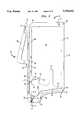
- FIG. 1is a perspective view of a finger stick device with a portion of an incision blade according to the present invention shown;
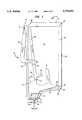
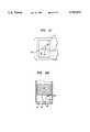
- FIG. 2is a cross-sectional view of the finger stick device illustrated in FIG. 1, taken in its quiescent state;
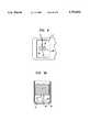
- FIG. 3is a sectional view of the incision blade projecting through a longitudinal slot in the finger stick device taken along line 3--3 in FIG. 5;
- FIG. 4is a side view of the incision blade taken along line 4--4 in FIG. 2;
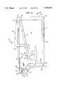
- FIG. 5is a cross-sectional view of the finger stick device illustrated in FIG. 1, taken while the blade is making an incision;
- FIG. 6is a cross-sectional view of the finger stick device illustrated in FIG. 1, taken after the finger stick mechanism was actuated;
- FIG. 7is a bottom view similar to FIG. 3 of an alternative embodiment of the incision blade
- FIG. 7Ais a side view similar to FIG. 4 of the alternative embodiment of the incision blade
- FIG. 8is a bottom view similar to FIG. 3 of another alternative embodiment of the incision blade
- FIG. 8Ais a side view similar to FIG. 4 of the alternative embodiment of the incision blade shown in FIG. 8;
- FIG. 9is a bottom view similar to FIG. 3 of another alternative embodiment of the incision blade.
- FIG. 9Ais a side view similar to FIG. 4 of the alternative embodiment of the incision blade shown in FIG. 9;
- FIG. 10is a bottom view similar to FIG. 3 of another alternative embodiment of the incision blade, and;
- FIG. 10Ais a side view similar to FIG. 4 of the alternative embodiment of the incision blade shown in FIG. 9.
- FIG. 1a perspective view of a finger stick device 10 which has been identified by the numeral 10.
- the finger stick device 10has an incision blade 12 in accordance with the present invention.
- the visible elements of the finger stick device 10 in FIG. 1include a housing 14, the incision blade 12, which is partially enclosed by the housing 14, and a lever arm 16, which protrudes from the housing 14.
- the position of the incision blade 12 and the lever arm 16 as shown in FIG. 1would not occur at the same time in normal use as explained below.
- the finger stick device 10 in a preferred embodimentis of the size that the housing 14 can be grasped by the hand of an operator.
- Typical dimensions for the housing 14include an overall length A of 2 inches, a width B of 1 inch, and a thickness C of 1/4 inch.
- the housing 14, which is elongated,has an internal cavity 18, an open end 20, which provides access to the internal cavity 18, and a closed end, which forms a base 22.
- a longitudinal slot 24is located in the base 22.
- the portion 26 of the base 22 containing the longitudinal slot 24extends away from the housing 12. This portion 26 serves to indicate to an operator the position of the longitudinal slot 24 with respect to the skin of the patient, not shown, since the exact position of the longitudinal slot 24 on the base 22 is obscured from the operator when used as explained below.
- the lever arm 16which is L-shaped, has a first end that is pivotally coupled to the housing 14 near its open end 20 and a second end which terminates in a catch 28.
- the catch 28extends through a first aperture 30 located in the housing 14 and is received by a ridge 32 in the housing 14.
- the finger stick device 10has a vertical reference member 34 located across the internal cavity 18 from the aperture 30.
- One end of the vertical reference member 34terminates in a projecting pin 36.
- a one way locksuch as a resilient projection 38, is located at the tip of the projection pin 36.
- the projection pin 36 and projection 38extend through a second aperture 40 located on the base 22 of the housing 14, and function to secure the vertical reference member 34 to the housing 14.
- the opposite end of the reference member 34terminates in a horizontal reference member 42, that also serves as a cover for the open end 20 of the housing.
- a channel 44 located at the open end 20 of the housing 14receives one end of the horizontal reference member 42.
- the vertical reference member 34 and the horizontal reference member 40comprise a support structure that is secured to the housing 14, thus, providing a mechanical coupling between components joined to the vertical reference member 34 or the horizontal reference member 42 and the housing 14.
- a blade pivot arm 46has one end that is pivotally attached to the vertical reference member 34 by a first living hinge 48. The opposite end of the blade pivot arm 46 terminates in a blade holder 50. At the upper surface of the blade holder 50 is a ramp 52, which has a positive slope. A detent 54 is located at the base of the ramp 52 and a tip 56 at the other end of the ramp 52.
- the incision blade 12which has a sharpened apex 58 and will be described in more detail below, is coupled to the blade holder 50.
- a bias member 60which is elongated, has one end that terminates in two legs, one of which is a push rod 62 and the other of which is a pawl 64.
- a notch 66is located above the push rod 62.
- the opposite end of the bias member 60is pivotally attached to the horizontal reference member 42 by a second living hinge 68, such that the bias member 60 abuts against, but is not attached to, the catch 28 of the lever arm 16, and such that a projection 70 on the push rod 62 is received by the detent 54.
- the first living hinge 48is axially prestressed, which causes the blade pivot arm 46 to lock in place.
- a lift lever 72which extends towards the open end 20 of the housing 14, is located on the blade pivot arm 46, intermediate the ends of the blade pivot arm 46. The lift lever 72 functions to help retract the incision blade 12 into the housing 14, as explained below.
- the incision blade 12 of the instant inventionhas at least three facets which extend from the blade holder 50 to the sharpened apex 58. In a preferred embodiment shown in FIGS. 1-6, the incision blade 12 has six facets of which only three 76 and 78 of the facets are shown in FIG. 2.
- the incision blade 12 as shown in FIG. 3projects out through the longitudinal slot 24.
- the incision blade 12projects downward, out of the page in FIG. 3, from the blade holder 50, which is shown broken away in hidden line, to the sharpened apex 58.
- the incision blade 12has six facets 76 and 78 of which four facets 76 are identical and extend from the blade holder 50 to the sharpened apex 58.
- the other two facets 78are identical to each other and extend from the blade holder 50 only partially to the sharpened apex 58, and each stop at an intermediate apex 80.
- typical dimensions of the incision blade 12include an overall width E of 0.0616 inches and a depth F of 0.0471 inches.
- the width G of the base of each of the facets 78, which are located in contact with the blade holder 50,is 0.0280 inches.
- the facets 78each project from the blade holder 50 to the intermediate apex 80, wherein the apexes 80 of the facets 78 are spaced apart by a distance H of 0.0191 inches.
- the incision blade 12is shown in the internal cavity 18 of the housing 14.
- the apex 58 of the incision blade 12 in this positionis located in the longitudinal slot 24 of the base 22. Only two of the facets 76 of the incision blade 12 are seen.
- the facets 76extend from the blade holder 50 to the apex 58 which is a distance J of 0.1150 inches in the preferred embodiment.
- the edge of the facets 76changes angle at the location of the intermediate apex 80 of the facets 78, which are not seen.
- the intermediate apex 80 of the facets 78is a distance L of 0.0794 inches from the blade holder 50.
- each of the two facets 78only one seen, have a pair of sides 82 which project up from the blade holder 50 to the formation of an angle ⁇ of 20 degrees in a preferred embodiment.
- the two opposing edges between the two adjoining facets 76form an angle ⁇ of 30 degrees.
- the finger stick device 10 as discloseddoes not have to be formed integrally, the vertical reference member 34, the horizontal reference member 42, the bias member 60, the lever arm 16, the blade pivot arm 46 including the blade holder 50, and the incision blade 12 can be formed integrally to ease manufacturing and fabrication.
- the finger stick mechanism including the bias memberneeds to be a resilient material and the incision blade 12 needs to be a non-brittle material which holds the edge of the facets (i.e., maintains its sharpness) and does not flash beyond the desired edge, point, wedge or chisel.
- the material that can satisfy the varied requirementscould be a polycarbonate such as Bayer Makralon 2458 or an acetal, an acetal copolymer or a polyester as supplied by Dupon, GE or Dow.
- the finger stick device 10is manufactured from only a plastic, after the single use, the finger stick device 10 can be disposed to a facility where the finger stick device 10 can be melted down to allow for recycling or reclaiming of the plastic.
- the operatorholds the finger stick device 10 with one hand such that the housing is firmly grasped and places the bottom surface flush against the patient's skin, not shown, at the location where the incision is desired, and squeezes the lever arm 16.
- the depression of the lever arm 16irreversibly actuates the finger stick mechanism located in the housing 14.
- the finger stick mechanismcauses the incision blade 12 to exit the housing and to puncture the patient's skin, and immediately thereafter, to retract back into the housing 14.
- the lever arm 16cannot reactuate the finger stick mechanism; therefore, the incision blade 12, once used, is located permanently within the housing 14.
- the flexed bias member 60simultaneously unflexes and pivots about the living hinge 68, causing the push rod 62 to rapidly traverse the ramp 52.
- the push rod 62irreversibly traverses the ramp 52, thereby depressing the blade holder 50 and causing it to pivot about the vertical reference member 34 (see FIG. 5).
- the incision blade 12As the incision blade 12 is pivoted, its apex 58 and multiple facets 76 and 78 move traversely through the longitudinal slot 24 and incises the patient's skin, until the blade pivot arm 46 abuts against the extended portion 26 of the housing 14.
- the incision blade 12makes an incision at a relatively predetermined depth sufficient to incise blood vessels, such that a blood sample can be drawn from the patient.
- the incision blade 14does not feather or flex because of its three dimensional shape.
- the incision blade 14 as formed in an injection moldhas sufficiently sharp edges to eliminate the need for additional sharpening before use.
- the pawl 64strikes the lift lever 72, whereupon the blade pivot arm 46 reverses direction and pivots the incision blade 12 into the housing 14. This retraction of the incision blade 12 is aided by the plastic memory of the first living hinge 48. Thus, immediately after the incision is implemented, the blade is caused to retract into the housing 12.
- the bias member 60has expended most of its stored energy. Due to this loss of energy, and due to the plastic memory of the second living hinge 68, the bias member 60 begins to pivot back to the quiescent position, whereupon the notch 66 engages the tip 56 of the ramp 52, thereby locking the blade pivot arm 46 in a final, stationary position as seen in FIG. 6.
- the plastic memory of the second living hinge 68urges the bias member 60 against the tip 56 of the ramp 52 on the blade holder 50. Thereafter, the lever arm 16 cannot extend into the housing 14 far enough to disengage the bias member 60 from the ramp 52, and the incision blade 12 is permanently locked within the housing 14.
- FIGS. 7 and 7Ashow an alternative incision blade 12', which projects out through the longitudinal slot 24.
- the incision blade 12'projects downward, out of the page in FIG. 7, from the blade holder 50, which is shown broken away in hidden line, to a sharpened apex 58'.
- the two opposing edges between adjoining facets 78'form an angle ⁇ ' of 30 degrees.
- FIGS. 8 and 8Ashow another alternative incision blade 82, which projects out through the longitudinal slot 24 in FIG. 8A.
- the incision blade 82projects downward, out of the page in FIG. 8, from the blade holder 50, which is shown broken away in hidden line, to a wedge-like sharpened apex 84.
- the incision blade 82has a pair of trapezoid shaped facets 86 forming a wedge, and an additional four facets 88 extending from the apex 84.
- the four facets 88are triangular-shaped and are located in two sets with the two in one set having a common edge.
- the incision blade 82has two additional facets 90. Each facet 90 extends from the larger base of one of the facets 86 to the blade holder 50.
- FIGS. 9 and 9Ashow another alternative incision blade 82', which projects out through the longitudinal slot 24.
- the incision blade 82'projects downward, out of the page in FIG. 9, from the blade holder 50, which is shown broken away in hidden line, to a chisel-like sharpened apex 84'.
- the incision blade 82'has a pair of rectangular shaped facets 86 forming a chisel.
- Six additional facets 88'extend from the edge of the facets 86', three from each facet 86' to the blade holder 50.
- the incision blade 82'has two additional edge facets 90' hidden from view.
- FIGS. 10 and 10Ashow another alternative incision blade 82", which projects out through the longitudinal slot 24.
- the incision blade 82"projects downward, out of the page in FIG. 10, from the blade holder 50, which is shown broken away in hidden line, to a wedge-like sharpened apex 84".
- the incision blade 82"has a pair of trapezoid shaped facets 86" forming a wedge, and an additional four facets 88" extending from the apex 84".
- the four facets 88"are triangular-shaped and are located in two sets with the two in one set having a commion edge.
- the trapezoid shaped facetsextend to the blade holder 50.
- the housing of the devicecan be formed out of two halves as disclosed in U.S. Pat. No. 5,133,730, in contrast to an open container and use the horizontal reference member as a cover.
Landscapes
- Health & Medical Sciences (AREA)
- Life Sciences & Earth Sciences (AREA)
- Heart & Thoracic Surgery (AREA)
- Medical Informatics (AREA)
- Biophysics (AREA)
- Pathology (AREA)
- Engineering & Computer Science (AREA)
- Biomedical Technology (AREA)
- Hematology (AREA)
- Physics & Mathematics (AREA)
- Molecular Biology (AREA)
- Surgery (AREA)
- Animal Behavior & Ethology (AREA)
- General Health & Medical Sciences (AREA)
- Public Health (AREA)
- Veterinary Medicine (AREA)
- Dermatology (AREA)
- Surgical Instruments (AREA)
Abstract
Description
Claims (20)
Priority Applications (1)
| Application Number | Priority Date | Filing Date | Title |
|---|---|---|---|
| US08/934,212US5782852A (en) | 1996-09-27 | 1997-09-19 | Plastic incision blade |
Applications Claiming Priority (2)
| Application Number | Priority Date | Filing Date | Title |
|---|---|---|---|
| US72236596A | 1996-09-27 | 1996-09-27 | |
| US08/934,212US5782852A (en) | 1996-09-27 | 1997-09-19 | Plastic incision blade |
Related Parent Applications (1)
| Application Number | Title | Priority Date | Filing Date |
|---|---|---|---|
| US72236596AContinuation | 1996-09-27 | 1996-09-27 |
Publications (1)
| Publication Number | Publication Date |
|---|---|
| US5782852Atrue US5782852A (en) | 1998-07-21 |
Family
ID=24901548
Family Applications (1)
| Application Number | Title | Priority Date | Filing Date |
|---|---|---|---|
| US08/934,212Expired - LifetimeUS5782852A (en) | 1996-09-27 | 1997-09-19 | Plastic incision blade |
Country Status (1)
| Country | Link |
|---|---|
| US (1) | US5782852A (en) |
Cited By (91)
| Publication number | Priority date | Publication date | Assignee | Title |
|---|---|---|---|---|
| US6042595A (en)* | 1999-03-02 | 2000-03-28 | Apls Co., Ltd. | Lancet apparatus for producing a precisely controlled incision |
| JP2002045351A (en)* | 2000-06-13 | 2002-02-12 | Bayer Corp | Lancet mechanism |
| US20030199895A1 (en)* | 2002-04-19 | 2003-10-23 | Pelikan Technologies, Inc. | Method and apparatus for penetrating tissue |
| US20050055041A1 (en)* | 2003-09-05 | 2005-03-10 | Sightrate B.V. | Device for separation of corneal epithelium |
| WO2005102166A1 (en)* | 2004-04-26 | 2005-11-03 | Asahi Polyslider Co., Ltd. | Lancet device for forming incision |
| WO2006001797A1 (en)* | 2004-06-14 | 2006-01-05 | Pelikan Technologies, Inc. | Low pain penetrating |
| US7025774B2 (en) | 2001-06-12 | 2006-04-11 | Pelikan Technologies, Inc. | Tissue penetration device |
| US20060106411A1 (en)* | 2004-11-16 | 2006-05-18 | Stat Medical Devices Inc. | Adjustable disposable/single-use blade lancet device and method |
| WO2006110573A1 (en)* | 2005-04-07 | 2006-10-19 | Becton, Dickinson And Company | Trigger activated lancet |
| US20060241669A1 (en)* | 2005-04-04 | 2006-10-26 | Stout Jeffrey T | Narrow-profile lancing device |
| US7198606B2 (en) | 2002-04-19 | 2007-04-03 | Pelikan Technologies, Inc. | Method and apparatus for a multi-use body fluid sampling device with analyte sensing |
| US7229458B2 (en) | 2002-04-19 | 2007-06-12 | Pelikan Technologies, Inc. | Method and apparatus for penetrating tissue |
| US7232451B2 (en) | 2002-04-19 | 2007-06-19 | Pelikan Technologies, Inc. | Method and apparatus for penetrating tissue |
| US7244265B2 (en) | 2002-04-19 | 2007-07-17 | Pelikan Technologies, Inc. | Method and apparatus for penetrating tissue |
| US7258693B2 (en) | 2002-04-19 | 2007-08-21 | Pelikan Technologies, Inc. | Device and method for variable speed lancet |
| US7291117B2 (en) | 2002-04-19 | 2007-11-06 | Pelikan Technologies, Inc. | Method and apparatus for penetrating tissue |
| US7297122B2 (en) | 2002-04-19 | 2007-11-20 | Pelikan Technologies, Inc. | Method and apparatus for penetrating tissue |
| US7297151B2 (en) | 2002-04-19 | 2007-11-20 | Elikan Technologies, Inc. | Method and apparatus for body fluid sampling with improved sensing |
| US7316700B2 (en) | 2001-06-12 | 2008-01-08 | Pelikan Technologies, Inc. | Self optimizing lancing device with adaptation means to temporal variations in cutaneous properties |
| US7331931B2 (en) | 2002-04-19 | 2008-02-19 | Pelikan Technologies, Inc. | Method and apparatus for penetrating tissue |
| US7344894B2 (en) | 2001-10-16 | 2008-03-18 | Agilent Technologies, Inc. | Thermal regulation of fluidic samples within a diagnostic cartridge |
| US7344507B2 (en) | 2002-04-19 | 2008-03-18 | Pelikan Technologies, Inc. | Method and apparatus for lancet actuation |
| US20080083119A1 (en)* | 2006-10-09 | 2008-04-10 | Schmidt G Gerry | Utility Knife |
| US20080109025A1 (en)* | 2006-11-06 | 2008-05-08 | Apex Biotechnology Corp. | Safety lancet |
| US7371247B2 (en) | 2002-04-19 | 2008-05-13 | Pelikan Technologies, Inc | Method and apparatus for penetrating tissue |
| US7374544B2 (en) | 2002-04-19 | 2008-05-20 | Pelikan Technologies, Inc. | Method and apparatus for penetrating tissue |
| WO2008066491A1 (en)* | 2006-12-01 | 2008-06-05 | Medipurpose Pte Ltd | A device for performing an incision |
| US7410468B2 (en) | 2002-04-19 | 2008-08-12 | Pelikan Technologies, Inc. | Method and apparatus for penetrating tissue |
| US7485128B2 (en) | 2002-04-19 | 2009-02-03 | Pelikan Technologies, Inc. | Method and apparatus for penetrating tissue |
| US7524293B2 (en) | 2002-04-19 | 2009-04-28 | Pelikan Technologies, Inc. | Method and apparatus for penetrating tissue |
| US7537571B2 (en) | 2001-06-12 | 2009-05-26 | Pelikan Technologies, Inc. | Integrated blood sampling analysis system with multi-use sampling module |
| US7547287B2 (en) | 2002-04-19 | 2009-06-16 | Pelikan Technologies, Inc. | Method and apparatus for penetrating tissue |
| US7563232B2 (en) | 2002-04-19 | 2009-07-21 | Pelikan Technologies, Inc. | Method and apparatus for penetrating tissue |
| US7604592B2 (en) | 2003-06-13 | 2009-10-20 | Pelikan Technologies, Inc. | Method and apparatus for a point of care device |
| US7648468B2 (en) | 2002-04-19 | 2010-01-19 | Pelikon Technologies, Inc. | Method and apparatus for penetrating tissue |
| US7666149B2 (en) | 1997-12-04 | 2010-02-23 | Peliken Technologies, Inc. | Cassette of lancet cartridges for sampling blood |
| US7674232B2 (en) | 2002-04-19 | 2010-03-09 | Pelikan Technologies, Inc. | Method and apparatus for penetrating tissue |
| US7682318B2 (en) | 2001-06-12 | 2010-03-23 | Pelikan Technologies, Inc. | Blood sampling apparatus and method |
| US7699791B2 (en) | 2001-06-12 | 2010-04-20 | Pelikan Technologies, Inc. | Method and apparatus for improving success rate of blood yield from a fingerstick |
| US7708750B2 (en) | 2001-07-23 | 2010-05-04 | Fos Holdings S.A. | Device for separating the epithelium layer from the surface of the cornea of an eye |
| US7717863B2 (en) | 2002-04-19 | 2010-05-18 | Pelikan Technologies, Inc. | Method and apparatus for penetrating tissue |
| US7749174B2 (en) | 2001-06-12 | 2010-07-06 | Pelikan Technologies, Inc. | Method and apparatus for lancet launching device intergrated onto a blood-sampling cartridge |
| EP1737359A4 (en)* | 2004-03-03 | 2010-07-28 | Helena Lab Corp | Load-controlled device for a patterned skin incision |
| US7780631B2 (en) | 1998-03-30 | 2010-08-24 | Pelikan Technologies, Inc. | Apparatus and method for penetration with shaft having a sensor for sensing penetration depth |
| US7822454B1 (en) | 2005-01-03 | 2010-10-26 | Pelikan Technologies, Inc. | Fluid sampling device with improved analyte detecting member configuration |
| US20100311230A1 (en)* | 2008-07-31 | 2010-12-09 | Mitsubishi Electric Corporation | Semiconductor device and method of fabricating the same |
| US7850621B2 (en) | 2003-06-06 | 2010-12-14 | Pelikan Technologies, Inc. | Method and apparatus for body fluid sampling and analyte sensing |
| US7862520B2 (en) | 2002-04-19 | 2011-01-04 | Pelikan Technologies, Inc. | Body fluid sampling module with a continuous compression tissue interface surface |
| US7892183B2 (en) | 2002-04-19 | 2011-02-22 | Pelikan Technologies, Inc. | Method and apparatus for body fluid sampling and analyte sensing |
| US7892185B2 (en) | 2002-04-19 | 2011-02-22 | Pelikan Technologies, Inc. | Method and apparatus for body fluid sampling and analyte sensing |
| US7901362B2 (en) | 2002-04-19 | 2011-03-08 | Pelikan Technologies, Inc. | Method and apparatus for penetrating tissue |
| US7909778B2 (en) | 2002-04-19 | 2011-03-22 | Pelikan Technologies, Inc. | Method and apparatus for penetrating tissue |
| US20110144537A1 (en)* | 2009-12-16 | 2011-06-16 | Facet Technologies, Llc | Blood sampling device with dual-link drive mechanism |
| US7976476B2 (en) | 2002-04-19 | 2011-07-12 | Pelikan Technologies, Inc. | Device and method for variable speed lancet |
| US8197421B2 (en) | 2002-04-19 | 2012-06-12 | Pelikan Technologies, Inc. | Method and apparatus for penetrating tissue |
| US8221334B2 (en) | 2002-04-19 | 2012-07-17 | Sanofi-Aventis Deutschland Gmbh | Method and apparatus for penetrating tissue |
| US8262614B2 (en) | 2003-05-30 | 2012-09-11 | Pelikan Technologies, Inc. | Method and apparatus for fluid injection |
| US8267870B2 (en) | 2002-04-19 | 2012-09-18 | Sanofi-Aventis Deutschland Gmbh | Method and apparatus for body fluid sampling with hybrid actuation |
| US8282576B2 (en) | 2003-09-29 | 2012-10-09 | Sanofi-Aventis Deutschland Gmbh | Method and apparatus for an improved sample capture device |
| US8337421B2 (en) | 2001-06-12 | 2012-12-25 | Sanofi-Aventis Deutschland Gmbh | Tissue penetration device |
| US8360992B2 (en) | 2002-04-19 | 2013-01-29 | Sanofi-Aventis Deutschland Gmbh | Method and apparatus for penetrating tissue |
| US8556829B2 (en) | 2002-04-19 | 2013-10-15 | Sanofi-Aventis Deutschland Gmbh | Method and apparatus for penetrating tissue |
| US8574895B2 (en) | 2002-12-30 | 2013-11-05 | Sanofi-Aventis Deutschland Gmbh | Method and apparatus using optical techniques to measure analyte levels |
| US8641644B2 (en) | 2000-11-21 | 2014-02-04 | Sanofi-Aventis Deutschland Gmbh | Blood testing apparatus having a rotatable cartridge with multiple lancing elements and testing means |
| US8652831B2 (en) | 2004-12-30 | 2014-02-18 | Sanofi-Aventis Deutschland Gmbh | Method and apparatus for analyte measurement test time |
| US8668656B2 (en) | 2003-12-31 | 2014-03-11 | Sanofi-Aventis Deutschland Gmbh | Method and apparatus for improving fluidic flow and sample capture |
| US8702624B2 (en) | 2006-09-29 | 2014-04-22 | Sanofi-Aventis Deutschland Gmbh | Analyte measurement device with a single shot actuator |
| US8721671B2 (en) | 2001-06-12 | 2014-05-13 | Sanofi-Aventis Deutschland Gmbh | Electric lancet actuator |
| US8784335B2 (en) | 2002-04-19 | 2014-07-22 | Sanofi-Aventis Deutschland Gmbh | Body fluid sampling device with a capacitive sensor |
| US8828203B2 (en) | 2004-05-20 | 2014-09-09 | Sanofi-Aventis Deutschland Gmbh | Printable hydrogels for biosensors |
| US8965476B2 (en) | 2010-04-16 | 2015-02-24 | Sanofi-Aventis Deutschland Gmbh | Tissue penetration device |
| JP2015070894A (en)* | 2013-10-02 | 2015-04-16 | テルモ株式会社 | Puncture tool |
| USD742004S1 (en) | 2014-02-18 | 2015-10-27 | “HTL-STREFA” Spólka Akcyjna | Skin incision device |
| US9226699B2 (en) | 2002-04-19 | 2016-01-05 | Sanofi-Aventis Deutschland Gmbh | Body fluid sampling module with a continuous compression tissue interface surface |
| US9248267B2 (en) | 2002-04-19 | 2016-02-02 | Sanofi-Aventis Deustchland Gmbh | Tissue penetration device |
| US9314194B2 (en) | 2002-04-19 | 2016-04-19 | Sanofi-Aventis Deutschland Gmbh | Tissue penetration device |
| US9351680B2 (en) | 2003-10-14 | 2016-05-31 | Sanofi-Aventis Deutschland Gmbh | Method and apparatus for a variable user interface |
| US9375169B2 (en) | 2009-01-30 | 2016-06-28 | Sanofi-Aventis Deutschland Gmbh | Cam drive for managing disposable penetrating member actions with a single motor and motor and control system |
| US9386944B2 (en) | 2008-04-11 | 2016-07-12 | Sanofi-Aventis Deutschland Gmbh | Method and apparatus for analyte detecting device |
| US9427532B2 (en) | 2001-06-12 | 2016-08-30 | Sanofi-Aventis Deutschland Gmbh | Tissue penetration device |
| US9474479B2 (en) | 2012-06-18 | 2016-10-25 | Facet Technologies, Llc | Uni-directional drive mechanism for lancing device |
| WO2017003761A1 (en) | 2015-06-30 | 2017-01-05 | The Gillette Company Llc | Polymeric cutting edge structures and method of manufacturing thereof |
| US9775553B2 (en) | 2004-06-03 | 2017-10-03 | Sanofi-Aventis Deutschland Gmbh | Method and apparatus for a fluid sampling device |
| US9795747B2 (en) | 2010-06-02 | 2017-10-24 | Sanofi-Aventis Deutschland Gmbh | Methods and apparatus for lancet actuation |
| US9820684B2 (en) | 2004-06-03 | 2017-11-21 | Sanofi-Aventis Deutschland Gmbh | Method and apparatus for a fluid sampling device |
| US9840013B2 (en) | 2008-04-29 | 2017-12-12 | Pacific Handy Cutter, Inc. | Safety cutter with blade change/storage mechanism |
| WO2018005399A1 (en) | 2016-06-28 | 2018-01-04 | The Gillette Company Llc | Cutting edge structures and method of manufacturing polymeric cutting edge structures |
| WO2018005398A1 (en) | 2016-06-28 | 2018-01-04 | The Gillette Company Llc | Polymeric cutting edge structures and method of manufacturing polymeric cutting edge structures |
| EP3666513A1 (en) | 2018-12-14 | 2020-06-17 | The Gillette Company LLC | Cutting-edge structures |
| CN111449660A (en)* | 2020-03-18 | 2020-07-28 | 天津华鸿科技股份有限公司 | Blood sampler |
| US11413191B2 (en)* | 2014-06-27 | 2022-08-16 | The Trustees Of Columbia University In The City Of New York | Apparatus for perforation and aspiration of inner ear |
Citations (3)
| Publication number | Priority date | Publication date | Assignee | Title |
|---|---|---|---|---|
| US5133730A (en)* | 1991-05-15 | 1992-07-28 | International Technidyne Corporation | Disposable-retractable finger stick device |
| US5201747A (en)* | 1992-02-20 | 1993-04-13 | Douglas Mastel | Ophthalmological surgical instrument having a triple edge tip |
| US5584846A (en)* | 1995-10-27 | 1996-12-17 | International Technidyne Corporation | Low cost disposable lancet |
- 1997
- 1997-09-19USUS08/934,212patent/US5782852A/ennot_activeExpired - Lifetime
Patent Citations (3)
| Publication number | Priority date | Publication date | Assignee | Title |
|---|---|---|---|---|
| US5133730A (en)* | 1991-05-15 | 1992-07-28 | International Technidyne Corporation | Disposable-retractable finger stick device |
| US5201747A (en)* | 1992-02-20 | 1993-04-13 | Douglas Mastel | Ophthalmological surgical instrument having a triple edge tip |
| US5584846A (en)* | 1995-10-27 | 1996-12-17 | International Technidyne Corporation | Low cost disposable lancet |
Cited By (195)
| Publication number | Priority date | Publication date | Assignee | Title |
|---|---|---|---|---|
| US7666149B2 (en) | 1997-12-04 | 2010-02-23 | Peliken Technologies, Inc. | Cassette of lancet cartridges for sampling blood |
| US7780631B2 (en) | 1998-03-30 | 2010-08-24 | Pelikan Technologies, Inc. | Apparatus and method for penetration with shaft having a sensor for sensing penetration depth |
| US8439872B2 (en) | 1998-03-30 | 2013-05-14 | Sanofi-Aventis Deutschland Gmbh | Apparatus and method for penetration with shaft having a sensor for sensing penetration depth |
| US6042595A (en)* | 1999-03-02 | 2000-03-28 | Apls Co., Ltd. | Lancet apparatus for producing a precisely controlled incision |
| EP1033109A1 (en)* | 1999-03-02 | 2000-09-06 | Apls Co., Ltd. | Lancet apparatus for producing a precisely controlled incision |
| EP1570792A1 (en)* | 1999-03-02 | 2005-09-07 | Asahi Polyslider Co., Ltd. | Lancet apparatus for producing a precisely controlled incision |
| JP2002045351A (en)* | 2000-06-13 | 2002-02-12 | Bayer Corp | Lancet mechanism |
| EP1163879A3 (en)* | 2000-06-13 | 2002-12-11 | Bayer Corporation | Lancing mechanism |
| US8641644B2 (en) | 2000-11-21 | 2014-02-04 | Sanofi-Aventis Deutschland Gmbh | Blood testing apparatus having a rotatable cartridge with multiple lancing elements and testing means |
| US8382683B2 (en) | 2001-06-12 | 2013-02-26 | Sanofi-Aventis Deutschland Gmbh | Tissue penetration device |
| US7316700B2 (en) | 2001-06-12 | 2008-01-08 | Pelikan Technologies, Inc. | Self optimizing lancing device with adaptation means to temporal variations in cutaneous properties |
| US9427532B2 (en) | 2001-06-12 | 2016-08-30 | Sanofi-Aventis Deutschland Gmbh | Tissue penetration device |
| US8845550B2 (en) | 2001-06-12 | 2014-09-30 | Sanofi-Aventis Deutschland Gmbh | Tissue penetration device |
| US7025774B2 (en) | 2001-06-12 | 2006-04-11 | Pelikan Technologies, Inc. | Tissue penetration device |
| US8721671B2 (en) | 2001-06-12 | 2014-05-13 | Sanofi-Aventis Deutschland Gmbh | Electric lancet actuator |
| US8679033B2 (en) | 2001-06-12 | 2014-03-25 | Sanofi-Aventis Deutschland Gmbh | Tissue penetration device |
| US8641643B2 (en) | 2001-06-12 | 2014-02-04 | Sanofi-Aventis Deutschland Gmbh | Sampling module device and method |
| US7682318B2 (en) | 2001-06-12 | 2010-03-23 | Pelikan Technologies, Inc. | Blood sampling apparatus and method |
| US8622930B2 (en) | 2001-06-12 | 2014-01-07 | Sanofi-Aventis Deutschland Gmbh | Tissue penetration device |
| US9694144B2 (en) | 2001-06-12 | 2017-07-04 | Sanofi-Aventis Deutschland Gmbh | Sampling module device and method |
| US9802007B2 (en) | 2001-06-12 | 2017-10-31 | Sanofi-Aventis Deutschland Gmbh | Methods and apparatus for lancet actuation |
| US8360991B2 (en) | 2001-06-12 | 2013-01-29 | Sanofi-Aventis Deutschland Gmbh | Tissue penetration device |
| US8337421B2 (en) | 2001-06-12 | 2012-12-25 | Sanofi-Aventis Deutschland Gmbh | Tissue penetration device |
| US8282577B2 (en) | 2001-06-12 | 2012-10-09 | Sanofi-Aventis Deutschland Gmbh | Method and apparatus for lancet launching device integrated onto a blood-sampling cartridge |
| US8216154B2 (en) | 2001-06-12 | 2012-07-10 | Sanofi-Aventis Deutschland Gmbh | Tissue penetration device |
| US8211037B2 (en) | 2001-06-12 | 2012-07-03 | Pelikan Technologies, Inc. | Tissue penetration device |
| US7041068B2 (en) | 2001-06-12 | 2006-05-09 | Pelikan Technologies, Inc. | Sampling module device and method |
| US8206319B2 (en) | 2001-06-12 | 2012-06-26 | Sanofi-Aventis Deutschland Gmbh | Tissue penetration device |
| US7699791B2 (en) | 2001-06-12 | 2010-04-20 | Pelikan Technologies, Inc. | Method and apparatus for improving success rate of blood yield from a fingerstick |
| US8206317B2 (en) | 2001-06-12 | 2012-06-26 | Sanofi-Aventis Deutschland Gmbh | Tissue penetration device |
| US8123700B2 (en) | 2001-06-12 | 2012-02-28 | Pelikan Technologies, Inc. | Method and apparatus for lancet launching device integrated onto a blood-sampling cartridge |
| US8016774B2 (en) | 2001-06-12 | 2011-09-13 | Pelikan Technologies, Inc. | Tissue penetration device |
| US7988645B2 (en) | 2001-06-12 | 2011-08-02 | Pelikan Technologies, Inc. | Self optimizing lancing device with adaptation means to temporal variations in cutaneous properties |
| US7981055B2 (en) | 2001-06-12 | 2011-07-19 | Pelikan Technologies, Inc. | Tissue penetration device |
| US7909775B2 (en) | 2001-06-12 | 2011-03-22 | Pelikan Technologies, Inc. | Method and apparatus for lancet launching device integrated onto a blood-sampling cartridge |
| US7850622B2 (en) | 2001-06-12 | 2010-12-14 | Pelikan Technologies, Inc. | Tissue penetration device |
| US9937298B2 (en) | 2001-06-12 | 2018-04-10 | Sanofi-Aventis Deutschland Gmbh | Tissue penetration device |
| US7749174B2 (en) | 2001-06-12 | 2010-07-06 | Pelikan Technologies, Inc. | Method and apparatus for lancet launching device intergrated onto a blood-sampling cartridge |
| US7537571B2 (en) | 2001-06-12 | 2009-05-26 | Pelikan Technologies, Inc. | Integrated blood sampling analysis system with multi-use sampling module |
| US7708750B2 (en) | 2001-07-23 | 2010-05-04 | Fos Holdings S.A. | Device for separating the epithelium layer from the surface of the cornea of an eye |
| US7344894B2 (en) | 2001-10-16 | 2008-03-18 | Agilent Technologies, Inc. | Thermal regulation of fluidic samples within a diagnostic cartridge |
| US9560993B2 (en) | 2001-11-21 | 2017-02-07 | Sanofi-Aventis Deutschland Gmbh | Blood testing apparatus having a rotatable cartridge with multiple lancing elements and testing means |
| US8808201B2 (en) | 2002-04-19 | 2014-08-19 | Sanofi-Aventis Deutschland Gmbh | Methods and apparatus for penetrating tissue |
| US8435190B2 (en) | 2002-04-19 | 2013-05-07 | Sanofi-Aventis Deutschland Gmbh | Method and apparatus for penetrating tissue |
| US20030199895A1 (en)* | 2002-04-19 | 2003-10-23 | Pelikan Technologies, Inc. | Method and apparatus for penetrating tissue |
| US7674232B2 (en) | 2002-04-19 | 2010-03-09 | Pelikan Technologies, Inc. | Method and apparatus for penetrating tissue |
| US7563232B2 (en) | 2002-04-19 | 2009-07-21 | Pelikan Technologies, Inc. | Method and apparatus for penetrating tissue |
| US9907502B2 (en) | 2002-04-19 | 2018-03-06 | Sanofi-Aventis Deutschland Gmbh | Method and apparatus for penetrating tissue |
| US9839386B2 (en) | 2002-04-19 | 2017-12-12 | Sanofi-Aventis Deustschland Gmbh | Body fluid sampling device with capacitive sensor |
| US7547287B2 (en) | 2002-04-19 | 2009-06-16 | Pelikan Technologies, Inc. | Method and apparatus for penetrating tissue |
| US7708701B2 (en) | 2002-04-19 | 2010-05-04 | Pelikan Technologies, Inc. | Method and apparatus for a multi-use body fluid sampling device |
| US7524293B2 (en) | 2002-04-19 | 2009-04-28 | Pelikan Technologies, Inc. | Method and apparatus for penetrating tissue |
| US7713214B2 (en) | 2002-04-19 | 2010-05-11 | Pelikan Technologies, Inc. | Method and apparatus for a multi-use body fluid sampling device with optical analyte sensing |
| US7717863B2 (en) | 2002-04-19 | 2010-05-18 | Pelikan Technologies, Inc. | Method and apparatus for penetrating tissue |
| US7731729B2 (en) | 2002-04-19 | 2010-06-08 | Pelikan Technologies, Inc. | Method and apparatus for penetrating tissue |
| US9795334B2 (en) | 2002-04-19 | 2017-10-24 | Sanofi-Aventis Deutschland Gmbh | Method and apparatus for penetrating tissue |
| US7491178B2 (en) | 2002-04-19 | 2009-02-17 | Pelikan Technologies, Inc. | Method and apparatus for penetrating tissue |
| US9724021B2 (en) | 2002-04-19 | 2017-08-08 | Sanofi-Aventis Deutschland Gmbh | Method and apparatus for penetrating tissue |
| US9498160B2 (en) | 2002-04-19 | 2016-11-22 | Sanofi-Aventis Deutschland Gmbh | Method for penetrating tissue |
| US7485128B2 (en) | 2002-04-19 | 2009-02-03 | Pelikan Technologies, Inc. | Method and apparatus for penetrating tissue |
| US9339612B2 (en) | 2002-04-19 | 2016-05-17 | Sanofi-Aventis Deutschland Gmbh | Tissue penetration device |
| US7833171B2 (en) | 2002-04-19 | 2010-11-16 | Pelikan Technologies, Inc. | Method and apparatus for penetrating tissue |
| US9314194B2 (en) | 2002-04-19 | 2016-04-19 | Sanofi-Aventis Deutschland Gmbh | Tissue penetration device |
| US9248267B2 (en) | 2002-04-19 | 2016-02-02 | Sanofi-Aventis Deustchland Gmbh | Tissue penetration device |
| US7410468B2 (en) | 2002-04-19 | 2008-08-12 | Pelikan Technologies, Inc. | Method and apparatus for penetrating tissue |
| US7862520B2 (en) | 2002-04-19 | 2011-01-04 | Pelikan Technologies, Inc. | Body fluid sampling module with a continuous compression tissue interface surface |
| US7874994B2 (en) | 2002-04-19 | 2011-01-25 | Pelikan Technologies, Inc. | Method and apparatus for penetrating tissue |
| US7875047B2 (en) | 2002-04-19 | 2011-01-25 | Pelikan Technologies, Inc. | Method and apparatus for a multi-use body fluid sampling device with sterility barrier release |
| US9226699B2 (en) | 2002-04-19 | 2016-01-05 | Sanofi-Aventis Deutschland Gmbh | Body fluid sampling module with a continuous compression tissue interface surface |
| US7892183B2 (en) | 2002-04-19 | 2011-02-22 | Pelikan Technologies, Inc. | Method and apparatus for body fluid sampling and analyte sensing |
| US7892185B2 (en) | 2002-04-19 | 2011-02-22 | Pelikan Technologies, Inc. | Method and apparatus for body fluid sampling and analyte sensing |
| US7901362B2 (en) | 2002-04-19 | 2011-03-08 | Pelikan Technologies, Inc. | Method and apparatus for penetrating tissue |
| US7901365B2 (en) | 2002-04-19 | 2011-03-08 | Pelikan Technologies, Inc. | Method and apparatus for penetrating tissue |
| US7909777B2 (en) | 2002-04-19 | 2011-03-22 | Pelikan Technologies, Inc | Method and apparatus for penetrating tissue |
| US9186468B2 (en) | 2002-04-19 | 2015-11-17 | Sanofi-Aventis Deutschland Gmbh | Method and apparatus for penetrating tissue |
| US7909778B2 (en) | 2002-04-19 | 2011-03-22 | Pelikan Technologies, Inc. | Method and apparatus for penetrating tissue |
| US7914465B2 (en) | 2002-04-19 | 2011-03-29 | Pelikan Technologies, Inc. | Method and apparatus for penetrating tissue |
| US7938787B2 (en) | 2002-04-19 | 2011-05-10 | Pelikan Technologies, Inc. | Method and apparatus for penetrating tissue |
| US9089294B2 (en) | 2002-04-19 | 2015-07-28 | Sanofi-Aventis Deutschland Gmbh | Analyte measurement device with a single shot actuator |
| US7976476B2 (en) | 2002-04-19 | 2011-07-12 | Pelikan Technologies, Inc. | Device and method for variable speed lancet |
| US7981056B2 (en) | 2002-04-19 | 2011-07-19 | Pelikan Technologies, Inc. | Methods and apparatus for lancet actuation |
| US7374544B2 (en) | 2002-04-19 | 2008-05-20 | Pelikan Technologies, Inc. | Method and apparatus for penetrating tissue |
| US7371247B2 (en) | 2002-04-19 | 2008-05-13 | Pelikan Technologies, Inc | Method and apparatus for penetrating tissue |
| US7988644B2 (en) | 2002-04-19 | 2011-08-02 | Pelikan Technologies, Inc. | Method and apparatus for a multi-use body fluid sampling device with sterility barrier release |
| US8007446B2 (en) | 2002-04-19 | 2011-08-30 | Pelikan Technologies, Inc. | Method and apparatus for penetrating tissue |
| US9089678B2 (en) | 2002-04-19 | 2015-07-28 | Sanofi-Aventis Deutschland Gmbh | Method and apparatus for penetrating tissue |
| US9072842B2 (en) | 2002-04-19 | 2015-07-07 | Sanofi-Aventis Deutschland Gmbh | Method and apparatus for penetrating tissue |
| US8062231B2 (en) | 2002-04-19 | 2011-11-22 | Pelikan Technologies, Inc. | Method and apparatus for penetrating tissue |
| US8079960B2 (en) | 2002-04-19 | 2011-12-20 | Pelikan Technologies, Inc. | Methods and apparatus for lancet actuation |
| US8905945B2 (en) | 2002-04-19 | 2014-12-09 | Dominique M. Freeman | Method and apparatus for penetrating tissue |
| US8845549B2 (en) | 2002-04-19 | 2014-09-30 | Sanofi-Aventis Deutschland Gmbh | Method for penetrating tissue |
| US8157748B2 (en) | 2002-04-19 | 2012-04-17 | Pelikan Technologies, Inc. | Methods and apparatus for lancet actuation |
| US8197423B2 (en) | 2002-04-19 | 2012-06-12 | Pelikan Technologies, Inc. | Method and apparatus for penetrating tissue |
| US8197421B2 (en) | 2002-04-19 | 2012-06-12 | Pelikan Technologies, Inc. | Method and apparatus for penetrating tissue |
| US8202231B2 (en) | 2002-04-19 | 2012-06-19 | Sanofi-Aventis Deutschland Gmbh | Method and apparatus for penetrating tissue |
| US7344507B2 (en) | 2002-04-19 | 2008-03-18 | Pelikan Technologies, Inc. | Method and apparatus for lancet actuation |
| US7331931B2 (en) | 2002-04-19 | 2008-02-19 | Pelikan Technologies, Inc. | Method and apparatus for penetrating tissue |
| US7297151B2 (en) | 2002-04-19 | 2007-11-20 | Elikan Technologies, Inc. | Method and apparatus for body fluid sampling with improved sensing |
| US7297122B2 (en) | 2002-04-19 | 2007-11-20 | Pelikan Technologies, Inc. | Method and apparatus for penetrating tissue |
| US8221334B2 (en) | 2002-04-19 | 2012-07-17 | Sanofi-Aventis Deutschland Gmbh | Method and apparatus for penetrating tissue |
| US8235915B2 (en) | 2002-04-19 | 2012-08-07 | Sanofi-Aventis Deutschland Gmbh | Method and apparatus for penetrating tissue |
| US8784335B2 (en) | 2002-04-19 | 2014-07-22 | Sanofi-Aventis Deutschland Gmbh | Body fluid sampling device with a capacitive sensor |
| US8690796B2 (en) | 2002-04-19 | 2014-04-08 | Sanofi-Aventis Deutschland Gmbh | Method and apparatus for penetrating tissue |
| US7198606B2 (en) | 2002-04-19 | 2007-04-03 | Pelikan Technologies, Inc. | Method and apparatus for a multi-use body fluid sampling device with analyte sensing |
| US8267870B2 (en) | 2002-04-19 | 2012-09-18 | Sanofi-Aventis Deutschland Gmbh | Method and apparatus for body fluid sampling with hybrid actuation |
| US7226461B2 (en) | 2002-04-19 | 2007-06-05 | Pelikan Technologies, Inc. | Method and apparatus for a multi-use body fluid sampling device with sterility barrier release |
| US7291117B2 (en) | 2002-04-19 | 2007-11-06 | Pelikan Technologies, Inc. | Method and apparatus for penetrating tissue |
| US8636673B2 (en) | 2002-04-19 | 2014-01-28 | Sanofi-Aventis Deutschland Gmbh | Tissue penetration device |
| US7229458B2 (en) | 2002-04-19 | 2007-06-12 | Pelikan Technologies, Inc. | Method and apparatus for penetrating tissue |
| US7258693B2 (en) | 2002-04-19 | 2007-08-21 | Pelikan Technologies, Inc. | Device and method for variable speed lancet |
| US8360992B2 (en) | 2002-04-19 | 2013-01-29 | Sanofi-Aventis Deutschland Gmbh | Method and apparatus for penetrating tissue |
| US8366637B2 (en) | 2002-04-19 | 2013-02-05 | Sanofi-Aventis Deutschland Gmbh | Method and apparatus for penetrating tissue |
| US8372016B2 (en) | 2002-04-19 | 2013-02-12 | Sanofi-Aventis Deutschland Gmbh | Method and apparatus for body fluid sampling and analyte sensing |
| US8382682B2 (en) | 2002-04-19 | 2013-02-26 | Sanofi-Aventis Deutschland Gmbh | Method and apparatus for penetrating tissue |
| US7244265B2 (en) | 2002-04-19 | 2007-07-17 | Pelikan Technologies, Inc. | Method and apparatus for penetrating tissue |
| US8388551B2 (en) | 2002-04-19 | 2013-03-05 | Sanofi-Aventis Deutschland Gmbh | Method and apparatus for multi-use body fluid sampling device with sterility barrier release |
| US8403864B2 (en) | 2002-04-19 | 2013-03-26 | Sanofi-Aventis Deutschland Gmbh | Method and apparatus for penetrating tissue |
| US8414503B2 (en) | 2002-04-19 | 2013-04-09 | Sanofi-Aventis Deutschland Gmbh | Methods and apparatus for lancet actuation |
| US8430828B2 (en) | 2002-04-19 | 2013-04-30 | Sanofi-Aventis Deutschland Gmbh | Method and apparatus for a multi-use body fluid sampling device with sterility barrier release |
| US7648468B2 (en) | 2002-04-19 | 2010-01-19 | Pelikon Technologies, Inc. | Method and apparatus for penetrating tissue |
| US7232451B2 (en) | 2002-04-19 | 2007-06-19 | Pelikan Technologies, Inc. | Method and apparatus for penetrating tissue |
| US8491500B2 (en) | 2002-04-19 | 2013-07-23 | Sanofi-Aventis Deutschland Gmbh | Methods and apparatus for lancet actuation |
| US8496601B2 (en) | 2002-04-19 | 2013-07-30 | Sanofi-Aventis Deutschland Gmbh | Methods and apparatus for lancet actuation |
| US8579831B2 (en) | 2002-04-19 | 2013-11-12 | Sanofi-Aventis Deutschland Gmbh | Method and apparatus for penetrating tissue |
| US8556829B2 (en) | 2002-04-19 | 2013-10-15 | Sanofi-Aventis Deutschland Gmbh | Method and apparatus for penetrating tissue |
| US8562545B2 (en) | 2002-04-19 | 2013-10-22 | Sanofi-Aventis Deutschland Gmbh | Tissue penetration device |
| US8574895B2 (en) | 2002-12-30 | 2013-11-05 | Sanofi-Aventis Deutschland Gmbh | Method and apparatus using optical techniques to measure analyte levels |
| US9034639B2 (en) | 2002-12-30 | 2015-05-19 | Sanofi-Aventis Deutschland Gmbh | Method and apparatus using optical techniques to measure analyte levels |
| US8262614B2 (en) | 2003-05-30 | 2012-09-11 | Pelikan Technologies, Inc. | Method and apparatus for fluid injection |
| US8251921B2 (en) | 2003-06-06 | 2012-08-28 | Sanofi-Aventis Deutschland Gmbh | Method and apparatus for body fluid sampling and analyte sensing |
| US7850621B2 (en) | 2003-06-06 | 2010-12-14 | Pelikan Technologies, Inc. | Method and apparatus for body fluid sampling and analyte sensing |
| US10034628B2 (en)* | 2003-06-11 | 2018-07-31 | Sanofi-Aventis Deutschland Gmbh | Low pain penetrating member |
| US9144401B2 (en)* | 2003-06-11 | 2015-09-29 | Sanofi-Aventis Deutschland Gmbh | Low pain penetrating member |
| US20060161194A1 (en)* | 2003-06-11 | 2006-07-20 | Freeman Dominique M | Low pain penetrating member |
| US7604592B2 (en) | 2003-06-13 | 2009-10-20 | Pelikan Technologies, Inc. | Method and apparatus for a point of care device |
| US20050055041A1 (en)* | 2003-09-05 | 2005-03-10 | Sightrate B.V. | Device for separation of corneal epithelium |
| US8282576B2 (en) | 2003-09-29 | 2012-10-09 | Sanofi-Aventis Deutschland Gmbh | Method and apparatus for an improved sample capture device |
| US8945910B2 (en) | 2003-09-29 | 2015-02-03 | Sanofi-Aventis Deutschland Gmbh | Method and apparatus for an improved sample capture device |
| US9351680B2 (en) | 2003-10-14 | 2016-05-31 | Sanofi-Aventis Deutschland Gmbh | Method and apparatus for a variable user interface |
| US9561000B2 (en) | 2003-12-31 | 2017-02-07 | Sanofi-Aventis Deutschland Gmbh | Method and apparatus for improving fluidic flow and sample capture |
| US8668656B2 (en) | 2003-12-31 | 2014-03-11 | Sanofi-Aventis Deutschland Gmbh | Method and apparatus for improving fluidic flow and sample capture |
| US8296918B2 (en) | 2003-12-31 | 2012-10-30 | Sanofi-Aventis Deutschland Gmbh | Method of manufacturing a fluid sampling device with improved analyte detecting member configuration |
| EP1737359A4 (en)* | 2004-03-03 | 2010-07-28 | Helena Lab Corp | Load-controlled device for a patterned skin incision |
| WO2005102166A1 (en)* | 2004-04-26 | 2005-11-03 | Asahi Polyslider Co., Ltd. | Lancet device for forming incision |
| US7879058B2 (en) | 2004-04-26 | 2011-02-01 | Asahi Polyslider Company, Limted | Lancet device for forming incision |
| US20070225741A1 (en)* | 2004-04-26 | 2007-09-27 | Yoshiaki Ikeda | Lancet Device for Forming Incision |
| US9261476B2 (en) | 2004-05-20 | 2016-02-16 | Sanofi Sa | Printable hydrogel for biosensors |
| US8828203B2 (en) | 2004-05-20 | 2014-09-09 | Sanofi-Aventis Deutschland Gmbh | Printable hydrogels for biosensors |
| US9820684B2 (en) | 2004-06-03 | 2017-11-21 | Sanofi-Aventis Deutschland Gmbh | Method and apparatus for a fluid sampling device |
| US9775553B2 (en) | 2004-06-03 | 2017-10-03 | Sanofi-Aventis Deutschland Gmbh | Method and apparatus for a fluid sampling device |
| WO2006001797A1 (en)* | 2004-06-14 | 2006-01-05 | Pelikan Technologies, Inc. | Low pain penetrating |
| US8105347B2 (en)* | 2004-11-16 | 2012-01-31 | Stat Medical Devices, Inc. | Adjustable disposable/single-use blade lancet device and method |
| US20060106411A1 (en)* | 2004-11-16 | 2006-05-18 | Stat Medical Devices Inc. | Adjustable disposable/single-use blade lancet device and method |
| US8652831B2 (en) | 2004-12-30 | 2014-02-18 | Sanofi-Aventis Deutschland Gmbh | Method and apparatus for analyte measurement test time |
| US7822454B1 (en) | 2005-01-03 | 2010-10-26 | Pelikan Technologies, Inc. | Fluid sampling device with improved analyte detecting member configuration |
| US20060241669A1 (en)* | 2005-04-04 | 2006-10-26 | Stout Jeffrey T | Narrow-profile lancing device |
| US8574255B2 (en) | 2005-04-04 | 2013-11-05 | Facet Technologies, Llc | Narrow-profile lancing device |
| WO2006107914A3 (en)* | 2005-04-04 | 2007-02-22 | Facet Technologies Llc | Narrow-profile lancing device |
| US20100160831A1 (en)* | 2005-04-04 | 2010-06-24 | Facet Technologies, Llc | Narrow-profile lancing device |
| WO2006110573A1 (en)* | 2005-04-07 | 2006-10-19 | Becton, Dickinson And Company | Trigger activated lancet |
| CN101179993B (en)* | 2005-04-07 | 2011-10-05 | 贝克顿·迪金森公司 | trigger activated lancet |
| US8709033B2 (en) | 2005-04-07 | 2014-04-29 | Becton, Dickinson And Company | Trigger activated lancet |
| US8702624B2 (en) | 2006-09-29 | 2014-04-22 | Sanofi-Aventis Deutschland Gmbh | Analyte measurement device with a single shot actuator |
| US7774942B2 (en) | 2006-10-09 | 2010-08-17 | Pacific Handy Cutter, Inc. | Utility knife |
| US8234790B2 (en) | 2006-10-09 | 2012-08-07 | Pacific Handy Cutter, Inc. | Utility knife |
| US20080083119A1 (en)* | 2006-10-09 | 2008-04-10 | Schmidt G Gerry | Utility Knife |
| US20080109025A1 (en)* | 2006-11-06 | 2008-05-08 | Apex Biotechnology Corp. | Safety lancet |
| US20100076472A1 (en)* | 2006-12-01 | 2010-03-25 | Medipurpose Pte Ltd | Device For Performing An Incision |
| CN101557759B (en)* | 2006-12-01 | 2014-05-07 | 医用私人有限公司 | device for cutting |
| JP2010511424A (en)* | 2006-12-01 | 2010-04-15 | メディパーパス ピーティーイー リミテッド | Device for making an incision |
| US8715307B2 (en)* | 2006-12-01 | 2014-05-06 | Medipurpose Pte Ltd | Device for performing an incision |
| WO2008066491A1 (en)* | 2006-12-01 | 2008-06-05 | Medipurpose Pte Ltd | A device for performing an incision |
| US9386944B2 (en) | 2008-04-11 | 2016-07-12 | Sanofi-Aventis Deutschland Gmbh | Method and apparatus for analyte detecting device |
| US9840013B2 (en) | 2008-04-29 | 2017-12-12 | Pacific Handy Cutter, Inc. | Safety cutter with blade change/storage mechanism |
| US20100311230A1 (en)* | 2008-07-31 | 2010-12-09 | Mitsubishi Electric Corporation | Semiconductor device and method of fabricating the same |
| US9375169B2 (en) | 2009-01-30 | 2016-06-28 | Sanofi-Aventis Deutschland Gmbh | Cam drive for managing disposable penetrating member actions with a single motor and motor and control system |
| US20110144537A1 (en)* | 2009-12-16 | 2011-06-16 | Facet Technologies, Llc | Blood sampling device with dual-link drive mechanism |
| US8512367B2 (en) | 2009-12-16 | 2013-08-20 | Facet Technologies, Llc | Blood sampling device with dual-link drive mechanism |
| US8965476B2 (en) | 2010-04-16 | 2015-02-24 | Sanofi-Aventis Deutschland Gmbh | Tissue penetration device |
| US9795747B2 (en) | 2010-06-02 | 2017-10-24 | Sanofi-Aventis Deutschland Gmbh | Methods and apparatus for lancet actuation |
| US9474479B2 (en) | 2012-06-18 | 2016-10-25 | Facet Technologies, Llc | Uni-directional drive mechanism for lancing device |
| JP2015070894A (en)* | 2013-10-02 | 2015-04-16 | テルモ株式会社 | Puncture tool |
| USD742004S1 (en) | 2014-02-18 | 2015-10-27 | “HTL-STREFA” Spólka Akcyjna | Skin incision device |
| US11413191B2 (en)* | 2014-06-27 | 2022-08-16 | The Trustees Of Columbia University In The City Of New York | Apparatus for perforation and aspiration of inner ear |
| WO2017003761A1 (en) | 2015-06-30 | 2017-01-05 | The Gillette Company Llc | Polymeric cutting edge structures and method of manufacturing thereof |
| US11059194B2 (en) | 2015-06-30 | 2021-07-13 | The Gillette Company Llc | Polymeric cutting edge structures and method of manufacturing polymeric cutting edge structures |
| US11597112B2 (en) | 2015-06-30 | 2023-03-07 | The Gillette Company Llc | Polymeric cutting edge structures and method of manufacturing polymeric cutting edge structures |
| WO2018005398A1 (en) | 2016-06-28 | 2018-01-04 | The Gillette Company Llc | Polymeric cutting edge structures and method of manufacturing polymeric cutting edge structures |
| WO2018005399A1 (en) | 2016-06-28 | 2018-01-04 | The Gillette Company Llc | Cutting edge structures and method of manufacturing polymeric cutting edge structures |
| US12350852B2 (en) | 2016-06-28 | 2025-07-08 | The Gillette Company Llc | Polymeric cutting edge structures and method of manufacturing polymeric cutting edge structures |
| EP3666513A1 (en) | 2018-12-14 | 2020-06-17 | The Gillette Company LLC | Cutting-edge structures |
| EP3666490A1 (en) | 2018-12-14 | 2020-06-17 | The Gillette Company LLC | Method of manufacturing cutting-edge structures |
| EP3666491A1 (en) | 2018-12-14 | 2020-06-17 | The Gillette Company LLC | Apparatus for manufacturing cutting-edge structures |
| CN111449660A (en)* | 2020-03-18 | 2020-07-28 | 天津华鸿科技股份有限公司 | Blood sampler |
| CN111449660B (en)* | 2020-03-18 | 2022-09-06 | 天津华鸿科技股份有限公司 | Blood sampler |
Similar Documents
| Publication | Publication Date | Title |
|---|---|---|
| US5782852A (en) | Plastic incision blade | |
| US5212879A (en) | Method for manufacturing a disposable-retractable finger stick device | |
| US20220134584A1 (en) | Safety cutting device | |
| US6513246B2 (en) | Utility knife | |
| US5851215A (en) | Low cost disposable lancet | |
| US5584846A (en) | Low cost disposable lancet | |
| US5385570A (en) | Surgical cutting instrument | |
| US5475925A (en) | Three-piece retractable-bladed knife | |
| US5529581A (en) | Lancet device for creating a skin incision | |
| US5314441A (en) | Disposable slicing lancet assembly | |
| US5662672A (en) | Single use, bi-directional linear motion lancet | |
| US8375588B2 (en) | Automatically retracting safety carton cutter | |
| US5481804A (en) | Retractable-bladed knife | |
| US6629985B1 (en) | Surgical scalpel with retractable guard | |
| CA1332784C (en) | Universal utility knife | |
| US8764781B2 (en) | Guarded surgical knife handle | |
| WO1996001080A1 (en) | Retractable-bladed surgical scalpel | |
| CA1328990C (en) | Wedge lock for pocket knife blade | |
| US6949109B2 (en) | Spring-actuated, retractable-bladed surgical scalpel | |
| CN104244852B (en) | Universal scalpel blade remover | |
| US20030229988A1 (en) | Safety cutter with retracting guard | |
| CN111166349A (en) | Blood sampler | |
| KR0132078Y1 (en) | Cutter | |
| KR200215582Y1 (en) | Scissors |
Legal Events
| Date | Code | Title | Description |
|---|---|---|---|
| STCF | Information on status: patent grant | Free format text:PATENTED CASE | |
| FEPP | Fee payment procedure | Free format text:PAYOR NUMBER ASSIGNED (ORIGINAL EVENT CODE: ASPN); ENTITY STATUS OF PATENT OWNER: LARGE ENTITY | |
| FPAY | Fee payment | Year of fee payment:4 | |
| REMI | Maintenance fee reminder mailed | ||
| FPAY | Fee payment | Year of fee payment:8 | |
| SULP | Surcharge for late payment | Year of fee payment:7 | |
| FPAY | Fee payment | Year of fee payment:12 | |
| AS | Assignment | Owner name:COMERICA BANK, CALIFORNIA Free format text:INTELLECTUAL PROPERTY SECURITY AGREEMENT;ASSIGNOR:INTERNATIONAL TECHNIDYNE CORPORATION;REEL/FRAME:026079/0301 Effective date:20110322 | |
| AS | Assignment | Owner name:INTERNATIONAL TECHNIDYNE CORPORATION, NEW JERSEY Free format text:RELEASE BY SECURED PARTY;ASSIGNOR:COMERICA BANK;REEL/FRAME:032123/0787 Effective date:20140123 | |
| AS | Assignment | Owner name:BLACKROCK KELSO CAPITAL CORPORATION, NEW YORK Free format text:SECURITY AGREEMENT;ASSIGNOR:INTERNATIONAL TECHNIDYNE CORPORATION;REEL/FRAME:032137/0798 Effective date:20140117 | |
| AS | Assignment | Owner name:INTERNATIONAL TECHNIDYNE CORPORATION, NEW JERSEY Free format text:ASSIGNMENT OF ASSIGNORS INTEREST;ASSIGNOR:MAWHIRT, JAMES A.;REEL/FRAME:032285/0784 Effective date:19980721 Owner name:INTERNATIONAL TECHNIDYNE CORPORATION, NEW JERSEY Free format text:ASSIGNMENT OF ASSIGNORS INTEREST;ASSIGNOR:FOGGIA, DONALD;REEL/FRAME:032248/0367 Effective date:19980721 Owner name:INTERNATIONAL TECHNIDYNE CORPORATION, NEW JERSEY Free format text:ASSIGNMENT OF ASSIGNORS INTEREST;ASSIGNOR:KUKLO, ANTHONY F.;REEL/FRAME:032248/0429 Effective date:19980721 | |
| AS | Assignment | Owner name:INTERNATIONAL TECHNIDYNE CORPORATION, NEW JERSEY Free format text:ASSIGNMENT OF ASSIGNORS INTEREST;ASSIGNOR:FOGGIA, DONALD;REEL/FRAME:032289/0609 Effective date:20140211 Owner name:INTERNATIONAL TECHNIDYNE CORPORATION, NEW JERSEY Free format text:ASSIGNMENT OF ASSIGNORS INTEREST;ASSIGNOR:KUKLO, ANTHONY F.;REEL/FRAME:032290/0118 Effective date:20140204 | |
| AS | Assignment | Owner name:ACCUMETRICS, INC., CALIFORNIA Free format text:RELEASE BY SECURED PARTY;ASSIGNOR:BLACKROCK CAPITAL INVESTMENT CORPORATION;REEL/FRAME:041519/0240 Effective date:20170126 Owner name:ACCRIVA DIANOGSTIC, INC., NEW JERSEY Free format text:RELEASE BY SECURED PARTY;ASSIGNOR:BLACKROCK CAPITAL INVESTMENT CORPORATION;REEL/FRAME:041519/0240 Effective date:20170126 |