US5782836A - Resecting tool for magnetic field environment - Google Patents
Resecting tool for magnetic field environmentDownload PDFInfo
- Publication number
- US5782836A US5782836AUS08/690,634US69063496AUS5782836AUS 5782836 AUS5782836 AUS 5782836AUS 69063496 AUS69063496 AUS 69063496AUS 5782836 AUS5782836 AUS 5782836A
- Authority
- US
- United States
- Prior art keywords
- rotor
- spindle
- bore
- axis
- resecting tool
- Prior art date
- Legal status (The legal status is an assumption and is not a legal conclusion. Google has not performed a legal analysis and makes no representation as to the accuracy of the status listed.)
- Expired - Fee Related
Links
- RTAQQCXQSZGOHL-UHFFFAOYSA-NTitaniumChemical compound[Ti]RTAQQCXQSZGOHL-UHFFFAOYSA-N0.000claimsabstractdescription19
- 239000010936titaniumSubstances0.000claimsabstractdescription19
- 229910052719titaniumInorganic materials0.000claimsabstractdescription19
- 210000000988bone and boneAnatomy0.000claimsabstractdescription8
- NRTOMJZYCJJWKI-UHFFFAOYSA-NTitanium nitrideChemical compound[Ti]#NNRTOMJZYCJJWKI-UHFFFAOYSA-N0.000claimsabstractdescription6
- UQZIWOQVLUASCR-UHFFFAOYSA-Nalumane;titaniumChemical compound[AlH3].[Ti]UQZIWOQVLUASCR-UHFFFAOYSA-N0.000claimsabstractdescription6
- 229910052751metalInorganic materials0.000claimsabstractdescription6
- 239000002184metalSubstances0.000claimsabstractdescription6
- 239000000463materialSubstances0.000claimsdescription9
- 238000000034methodMethods0.000claimsdescription4
- 238000001356surgical procedureMethods0.000abstractdescription6
- CYKMNKXPYXUVPR-UHFFFAOYSA-N[C].[Ti]Chemical compound[C].[Ti]CYKMNKXPYXUVPR-UHFFFAOYSA-N0.000abstractdescription4
- 238000002595magnetic resonance imagingMethods0.000description6
- 239000010935stainless steelSubstances0.000description3
- 229910001220stainless steelInorganic materials0.000description3
- 238000007740vapor depositionMethods0.000description3
- CWYNVVGOOAEACU-UHFFFAOYSA-NFe2+Chemical compound[Fe+2]CWYNVVGOOAEACU-UHFFFAOYSA-N0.000description2
- 150000002739metalsChemical class0.000description2
- 238000007789sealingMethods0.000description2
- 229910000975Carbon steelInorganic materials0.000description1
- RYGMFSIKBFXOCR-UHFFFAOYSA-NCopperChemical compound[Cu]RYGMFSIKBFXOCR-UHFFFAOYSA-N0.000description1
- 229910000831SteelInorganic materials0.000description1
- DMFGNRRURHSENX-UHFFFAOYSA-Nberyllium copperChemical compound[Be].[Cu]DMFGNRRURHSENX-UHFFFAOYSA-N0.000description1
- 239000010962carbon steelSubstances0.000description1
- 239000011248coating agentSubstances0.000description1
- 238000000576coating methodMethods0.000description1
- 229910052802copperInorganic materials0.000description1
- 239000010949copperSubstances0.000description1
- 230000001627detrimental effectEffects0.000description1
- 238000012631diagnostic techniqueMethods0.000description1
- 238000002224dissectionMethods0.000description1
- 239000013536elastomeric materialSubstances0.000description1
- 238000002271resectionMethods0.000description1
- 239000010959steelSubstances0.000description1
- 239000003351stiffenerSubstances0.000description1
- UONOETXJSWQNOL-UHFFFAOYSA-Ntungsten carbideChemical compound[W+]#[C-]UONOETXJSWQNOL-UHFFFAOYSA-N0.000description1
- 210000001835visceraAnatomy0.000description1
Images

Classifications
- A—HUMAN NECESSITIES
- A61—MEDICAL OR VETERINARY SCIENCE; HYGIENE
- A61B—DIAGNOSIS; SURGERY; IDENTIFICATION
- A61B17/00—Surgical instruments, devices or methods
- A61B17/16—Instruments for performing osteoclasis; Drills or chisels for bones; Trepans
- A61B17/1613—Component parts
- A61B17/162—Chucks or tool parts which are to be held in a chuck
- A—HUMAN NECESSITIES
- A61—MEDICAL OR VETERINARY SCIENCE; HYGIENE
- A61B—DIAGNOSIS; SURGERY; IDENTIFICATION
- A61B17/00—Surgical instruments, devices or methods
- A61B17/16—Instruments for performing osteoclasis; Drills or chisels for bones; Trepans
- A61B17/1613—Component parts
- A61B17/1633—Sleeves, i.e. non-rotating parts surrounding the bit shaft, e.g. the sleeve forming a single unit with the bit shaft
- A—HUMAN NECESSITIES
- A61—MEDICAL OR VETERINARY SCIENCE; HYGIENE
- A61B—DIAGNOSIS; SURGERY; IDENTIFICATION
- A61B17/00—Surgical instruments, devices or methods
- A61B17/32—Surgical cutting instruments
- A61B17/320016—Endoscopic cutting instruments, e.g. arthroscopes, resectoscopes
- A61B17/32002—Endoscopic cutting instruments, e.g. arthroscopes, resectoscopes with continuously rotating, oscillating or reciprocating cutting instruments
- A—HUMAN NECESSITIES
- A61—MEDICAL OR VETERINARY SCIENCE; HYGIENE
- A61B—DIAGNOSIS; SURGERY; IDENTIFICATION
- A61B17/00—Surgical instruments, devices or methods
- A61B17/16—Instruments for performing osteoclasis; Drills or chisels for bones; Trepans
- A61B17/1613—Component parts
- A61B17/1615—Drill bits, i.e. rotating tools extending from a handpiece to contact the worked material
- A—HUMAN NECESSITIES
- A61—MEDICAL OR VETERINARY SCIENCE; HYGIENE
- A61B—DIAGNOSIS; SURGERY; IDENTIFICATION
- A61B17/00—Surgical instruments, devices or methods
- A61B17/16—Instruments for performing osteoclasis; Drills or chisels for bones; Trepans
- A61B17/1613—Component parts
- A61B17/1628—Motors; Power supplies
- A—HUMAN NECESSITIES
- A61—MEDICAL OR VETERINARY SCIENCE; HYGIENE
- A61B—DIAGNOSIS; SURGERY; IDENTIFICATION
- A61B17/00—Surgical instruments, devices or methods
- A61B2017/00535—Surgical instruments, devices or methods pneumatically or hydraulically operated
- A61B2017/00544—Surgical instruments, devices or methods pneumatically or hydraulically operated pneumatically
- A—HUMAN NECESSITIES
- A61—MEDICAL OR VETERINARY SCIENCE; HYGIENE
- A61B—DIAGNOSIS; SURGERY; IDENTIFICATION
- A61B17/00—Surgical instruments, devices or methods
- A61B2017/00831—Material properties
- Y—GENERAL TAGGING OF NEW TECHNOLOGICAL DEVELOPMENTS; GENERAL TAGGING OF CROSS-SECTIONAL TECHNOLOGIES SPANNING OVER SEVERAL SECTIONS OF THE IPC; TECHNICAL SUBJECTS COVERED BY FORMER USPC CROSS-REFERENCE ART COLLECTIONS [XRACs] AND DIGESTS
- Y10—TECHNICAL SUBJECTS COVERED BY FORMER USPC
- Y10S—TECHNICAL SUBJECTS COVERED BY FORMER USPC CROSS-REFERENCE ART COLLECTIONS [XRACs] AND DIGESTS
- Y10S415/00—Rotary kinetic fluid motors or pumps
- Y10S415/904—Tool drive turbine, e.g. dental drill
Definitions
- the present inventionrelates in general to surgical instruments and, in particular, to a pneumatic resecting tool suitable for use in environments containing strong magnetic fields.
- Surgical tools for use in the dissection of bone during surgical proceduresare conventional in the art. Many such tools employ pneumatic motors to rotate the cutting element of a resecting tool.
- such surgical instrumentscomprise a motor portion having a rotary shaft, a resecting tool having a cutting element, and means for connecting the resecting tool to a spindle or collet of the rotary shaft.
- These surgical instrumentshave been created from carbon steel because of the need for high material hardness and ability to withstand the wear of operating at high speeds.
- thin hardened casessuch as titanium nitride and titanium aluminum nitride have been applied to the bore of the motor housing to reduce wear caused by the rotating vanes.
- resecting toolsin some instances have been formed of tungsten carbide.
- MRImagnetic resonance imaging
- These machinesprovide an image of internal organs of the human body. Surgeons may utilize the images from such machines to guide them in performing subsequent surgery. It would be advantageous to be able to simultaneously perform surgery using pneumatic resecting tools while the MRI is taking place. Also, the resident high magnetic field will attract magnetic objects potentially creating unguided missles. However, because of the ferrous metal in the motors, these pneumatic resecting tools are not used.
- nonferrous metalsare generally softer and wear more quickly. For this reason, nonferrous metals such as titanium have traditionally only been used in hand tools such as pliers and nippers, not in pneumatic resecting motors, which rotate at speeds.
- a pneumatic surgical tool for the resection of bone during surgical proceduresis driven by a pneumatic motor housing subjected to air pressure from an outside source which enters through air inlet passages and exits through air outlet passages in the housing.
- a rotary shaft or rotoris located within a bore in the motor housing and has an axis parallel to and offset from an axis of the bore.
- the rotary shafthas a spindle extending out of the motor housing and is rotatably supported by bearings.
- a resecting tool with a cutting elementis connected to the spindle of the rotary shaft and rotated by the motor.
- a chuckconnects to the spindle and secures the resecting tool.
- the present inventionimproves the conventional surgical tool by creating substantially all of the components of the instrument from titanium.
- the bore and the cutting tip of the resecting toolhave thin hard metal cases to increase the hardness of the tool and its resistance to wear.
- the thin coatingis applied by known vapor deposition techniques and can be titanium nitride, titanium aluminum nitride, or titanium carbon nitride.
- the forward bearingis formed of beryllium copper and in one embodiment, the rearward bearing is formed of stainless steel.
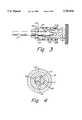
- FIG. 1is a partial cross-sectional side view of a pneumatic motor for a resecting tool constructed according to the present invention.
- FIG. 2is a side elevational view of a cutting tool constructed according to the present invention and for use with the motor of FIG. 1.
- FIG. 3is a partial cross-sectional side view of the chuck for the motor of FIG. 1, with the cutting tool of FIG. 2 secured therein.
- FIG. 4is a cross-sectional view of the motor of the resecting tool of FIG. 1, taken along the line 4--4 of FIG. 1.
- the surgical instrument 11has a pneumatic driven motor 13 having a housing 17 surrounded by an outer sleeve 15, both formed of titanium.
- Motor housing 17has a cylindrical bore 19. Pressurized air is supplied to bore 19 through a plurality of air inlet passages 21.
- Bore 19also has a plurality of air outlet passages 22 opposite air inlet passages 21 for the discharge of pressurized air.
- a rotor or rotary shaft 23is located inside bore 19 and has an axis parallel to but offset from the axis of bore 19, as illustrated also in FIG. 4.
- the axis of rotor 23is located closer to the side of bore 19 containing air inlet passages 21 and away from the side of bore 19 containing air outlet passages 22.
- Rotor 23is also formed of titanium.
- Rotor 23is rotatably supported in bore 19 by roller bearings 25, 27 which are axially spaced apart from each other.
- Roller bearing 25is preferably of berrylium copper. In one embodiment, stainless steel was employed for the rearward bearing 27 without any significant detrimental effects on the magnetic field of the MRI machine.
- rotor 23has three slots extending radially from the axis of rotor 23 and spaced 120 degrees apart from each other.
- a nonmetallic vane 31is located inside each slot, and each vane 31 can slide radially inward or outward relative to the axis of rotor 23.
- bore 19has a hardened case of titanium nitride, titanium aluminum nitride, or titanium carbon nitride.
- the caseis very thin, approximately 0.0001 inch.
- the caseis formed by known vapor deposition techniques.
- the casehas a hardness in the range from about 87 to 92 Rockwell "C".
- a spindle 33is connected to the end of rotor 23 extending out of bore 19. Spindle 33 protrudes from the forward end of motor 13 and is integrally formed with rotor 23.
- a permanent nonmetallic seal 34is located in the forward end of outer sleeve 15 for sealing around rotor 23.
- a nonmetallic safety seal 34is located outside outer sleeve 15, also for sealing against leakage of oil from the interior of housing 17. Safety seal 34 is removed after each use and replaced with a new seal.
- Spindle 33has a plurality of threads 35 on its exterior.
- a socket 37extends into spindle 33.
- Socket 37is cylindrical and has a shoulder or base 39 that is perpendicular to the axis of rotor 23.
- a slot 41extends rearward from base 39. Slot 41 is generally rectangular, having two opposed flat faces 43 which serve as torque transmitting surfaces. Faces 43 are spaced equidistant from the axis of rotor 23.
- a chuck 45 formed of titaniumis secured to spindle 33.
- Chuck 45has an inner sleeve 47 which has internal threads that mate with threads 35.
- Inner sleeve 47has a protruding neck 48 which has a cylindrical axial passage 49. Passage 49 aligns with and is the same diameter as cylindrical socket 37.
- a plurality of apertures 51are located in neck 48. Apertures 51 extend from passage 49 to the exterior and are spaced circumferentially apart.
- a ball 53is positioned within each aperture 51.
- Balls 53are capable of moving inward, protruding into passage 49 as shown, and moving outward.
- balls 53are radially outward of passage 49.
- An outer sleeve 55is carried on inner sleeve 47.
- Outer sleeve 55is capable of axial movement relative to inner sleeve 47 between a locked position shown in FIG. 1 and a released position, forward of the locked position.
- a cam surface 57 on outer sleeve 55moves forward of balls 53, allowing them to move to the released position.
- cam 57retains balls 53 in the locked position.
- Inner sleeve 47, outer sleeve 55, balls 53 and spring 59are all formed with titanium.
- a resecting tool 61is adapted to be coupled to spindle 33.
- Resecting tool 61is formed of a nonferrous material, preferably titanium.
- Resecting tool 61has a shaft 63 with a cutting tip 65 on its end.
- Preferably at least cutting tip 65has a hardened case of titanium nitride, titanium aluminum nitride, or titanium carbon nitride.
- the caseis very thin, approximately 0.0001 inch.
- the caseis formed by known vapor deposition techniques in the same manner as the case on bore 19 of motor housing 17.
- Resecting tool 61also has a torque transmitting tang 67.
- Tang 67is located on the axis of shaft 63, and has two flat sides 68 which face opposite each other. Tang 67 protrudes from a rearward facing shoulder 69. Tang 67 is adapted to be closely received within slot 41 (FIG. 3) with faces 68 in engagement with faces 43.
- a groove 71extends circumferentially around shaft 63 for receiving balls 53.
- motor housing 17has a rearward end that has a mandrel 72.
- An inner hose 73 of elastomeric materialsecures to mandrel 72.
- a stiffener spring 75 of nonferrous materialencircles inner hose 73.
- An outer hose 77is secured to housing 17, defining an annular passage surrounding inner hose 73.
- Surgical instrument 11is capable of operating in a high strength field created by an MRI machine.
- the rearward set of bearings 25may be of stainless steel, substantially all of the other components are of titanium, therefore are not influenced by the magnetic field.
- the primary advantage of this inventionis the nonmagnetic nature of titanium which allows use of these surgical instruments in the presence of magnetic fields without experiencing any external forces. Magnetic fields occur where magnetic resonance imaging (MRI) machines and other related devices are used. Another advantage is the lightweight nature of titanium relative to the typical ferrous materials used for surgical tools.
- MRImagnetic resonance imaging
Landscapes
- Health & Medical Sciences (AREA)
- Surgery (AREA)
- Life Sciences & Earth Sciences (AREA)
- Biomedical Technology (AREA)
- Medical Informatics (AREA)
- Orthopedic Medicine & Surgery (AREA)
- Veterinary Medicine (AREA)
- Engineering & Computer Science (AREA)
- Public Health (AREA)
- Heart & Thoracic Surgery (AREA)
- Nuclear Medicine, Radiotherapy & Molecular Imaging (AREA)
- Molecular Biology (AREA)
- Animal Behavior & Ethology (AREA)
- General Health & Medical Sciences (AREA)
- Dentistry (AREA)
- Oral & Maxillofacial Surgery (AREA)
- Surgical Instruments (AREA)
Abstract
Description
Claims (12)
Priority Applications (2)
| Application Number | Priority Date | Filing Date | Title |
|---|---|---|---|
| US08/690,634US5782836A (en) | 1996-07-30 | 1996-07-30 | Resecting tool for magnetic field environment |
| US09/110,729US6033408A (en) | 1996-07-30 | 1998-07-06 | Resecting tool for magnetic field environment |
Applications Claiming Priority (1)
| Application Number | Priority Date | Filing Date | Title |
|---|---|---|---|
| US08/690,634US5782836A (en) | 1996-07-30 | 1996-07-30 | Resecting tool for magnetic field environment |
Related Child Applications (1)
| Application Number | Title | Priority Date | Filing Date |
|---|---|---|---|
| US09/110,729Continuation-In-PartUS6033408A (en) | 1996-07-30 | 1998-07-06 | Resecting tool for magnetic field environment |
Publications (1)
| Publication Number | Publication Date |
|---|---|
| US5782836Atrue US5782836A (en) | 1998-07-21 |
Family
ID=24773278
Family Applications (1)
| Application Number | Title | Priority Date | Filing Date |
|---|---|---|---|
| US08/690,634Expired - Fee RelatedUS5782836A (en) | 1996-07-30 | 1996-07-30 | Resecting tool for magnetic field environment |
Country Status (1)
| Country | Link |
|---|---|
| US (1) | US5782836A (en) |
Cited By (42)
| Publication number | Priority date | Publication date | Assignee | Title |
|---|---|---|---|---|
| US5957945A (en)* | 1996-09-24 | 1999-09-28 | Xomed Surgical Products, Inc. | Powered handpiece system |
| US5993453A (en)* | 1997-10-15 | 1999-11-30 | Huntington Medical Research Institutes | Controlled-depth bone cutter |
| US6139214A (en)* | 1998-12-14 | 2000-10-31 | Endius Incorporated | Quick disconnect coupling for surgical instrument |
| US6245086B1 (en)* | 1995-08-18 | 2001-06-12 | Karl Storz Gmbh & Co., Kg | Motor-driven medical instrument with flexible shaft |
| WO2001060261A3 (en)* | 2000-02-18 | 2002-04-04 | Stryker Corp | Surgical tool system with variable length attachments |
| US20020151902A1 (en)* | 2001-03-21 | 2002-10-17 | Medtronic, Inc. | Surgical instrument with rotary cutting member and quick release coupling arrangement |
| US20020165549A1 (en)* | 2001-04-30 | 2002-11-07 | Medtronic, Inc. | Surgical instrument and attachment |
| US20030023256A1 (en)* | 2001-03-21 | 2003-01-30 | Medtronic, Inc. D/B/A Medtronic Midas Rex | Surgical instrument with rotary cutting member and quick release coupling arrangement |
| US20030070301A1 (en)* | 2001-10-16 | 2003-04-17 | Bettcher Industries, Inc. | Pneumatic hand tool with improved control valve |
| US6595984B1 (en)* | 2000-03-28 | 2003-07-22 | Microline, Inc. | Laparoscopic instrument with a detachable tip |
| US20030163134A1 (en)* | 2001-03-21 | 2003-08-28 | Medtronic, Inc. D/B/A Medtronic Midas Rex | Surgical instrument with rotary cutting member and quick release coupling arrangement |
| US6716483B1 (en)* | 2001-06-26 | 2004-04-06 | Moulder Services, Inc. | Methods for cutting articles containing at least a substantial amount of wood |
| US20040122460A1 (en)* | 2002-12-20 | 2004-06-24 | Medtronic, Inc. | Surgical instrument with telescoping attachment |
| US20040152968A1 (en)* | 2003-01-17 | 2004-08-05 | Iversen Alfred A. | MRI-compatible surgical instruments |
| US6780189B2 (en) | 2002-06-07 | 2004-08-24 | Medtronic, Inc. | Surgical instrument with a collet locking and indexing system |
| US20040228702A1 (en)* | 2003-05-01 | 2004-11-18 | Lewmar Limited | Fixing assemblies and methods |
| US20050065529A1 (en)* | 2003-09-11 | 2005-03-24 | Mingyan Liu | Impulsive percussion instruments for endplate preparation |
| US20050093392A1 (en)* | 2003-10-31 | 2005-05-05 | Medtronic, Inc. | Electric motor having nanocrystalline alloy component for use in surgical procedure |
| FR2861574A1 (en)* | 2003-10-31 | 2005-05-06 | Medtronic Inc | CONNECTING SYSTEM FOR SURGICAL INSTRUMENT |
| US20050192585A1 (en)* | 2004-02-27 | 2005-09-01 | Medtronic, Inc. | Surgical saw collet with closed drive ring |
| US20060025792A1 (en)* | 2004-08-02 | 2006-02-02 | Gibson Roger A | Surgical instrument attachment system |
| US20060046856A1 (en)* | 2004-08-31 | 2006-03-02 | Medtronic, Inc. | Self-lubricating surgical instrument |
| US20060089623A1 (en)* | 2004-10-21 | 2006-04-27 | Medtronic, Inc. | Surgical instrument with wear-resistant housing and method of operating same |
| US20060178672A1 (en)* | 2002-12-20 | 2006-08-10 | Medtronic, Inc. D/B/A Medtronic Midas Rex | Surgical instrument with angled attachment |
| US20060248624A1 (en)* | 2005-04-25 | 2006-11-09 | Pieczynski Darren E | Heat containment hand warming device |
| WO2007002230A1 (en)* | 2005-06-25 | 2007-01-04 | Stryker Corporation | Surgical handpiece with compact clutch and anti-wobble coupling head |
| FR2902311A1 (en)* | 2006-06-14 | 2007-12-21 | Wai Ping Jean Claude Yeung | Surgical drilling instrument for installing endo-osseous implant, has perforator with assembling zone composed of cooperating zone extended towards shank by receiving zone that is delimited between proximal and distal stops |
| EP1880683A1 (en)* | 2006-07-18 | 2008-01-23 | Bien-Air Holding SA | Clutch assembly for dental or surgical handpiece |
| US20080208229A1 (en)* | 2007-02-28 | 2008-08-28 | Medtronic, Inc. | Motor Assembly for a Powered Surgical Instrument |
| US20090326540A1 (en)* | 2008-06-30 | 2009-12-31 | Medtronic Xomed, Inc. | Chuck for Reciprocating Surgical Instrument |
| EP1511956A4 (en)* | 2002-06-11 | 2010-05-05 | Medtronic Inc D B A Medtronic | Apparatus for containing noise generated by a pneumatically powered surgical instrument and related method |
| USD782042S1 (en) | 2015-03-25 | 2017-03-21 | Medtronic Ps Medical, Inc. | Surgical tool |
| USD790699S1 (en) | 2015-03-25 | 2017-06-27 | Medtronic Ps Medical, Inc. | Surgical tool |
| US9757129B2 (en) | 2013-07-08 | 2017-09-12 | Covidien Lp | Coupling member configured for use with surgical devices |
| USD800907S1 (en) | 2015-03-25 | 2017-10-24 | Medtronic Ps Medical, Inc. | Surgical tool |
| USD800906S1 (en) | 2015-03-25 | 2017-10-24 | Medtronic Ps Medical, Inc. | Surgical tool |
| USD800903S1 (en) | 2016-02-09 | 2017-10-24 | Medtronic Ps Medical, Inc. | Surgical tool |
| US10080579B2 (en) | 2015-03-25 | 2018-09-25 | Medtronic Ps Medical, Inc. | Pin drive rotary surgical cutting tools and powered handpieces |
| US10314610B2 (en) | 2015-03-25 | 2019-06-11 | Medtronic Ps Medical, Inc. | Slanted drive axis rotary surgical cutting tools and powered handpieces |
| WO2019168976A1 (en)* | 2018-02-28 | 2019-09-06 | Medtronic Ps Medical, Inc. | Oil-less pneumatic motor |
| US10849634B2 (en) | 2018-06-20 | 2020-12-01 | Medtronic Xomed, Inc. | Coupling portion for rotary surgical cutting systems |
| US12440902B2 (en) | 2024-01-08 | 2025-10-14 | Medtronic Ps Medical, Inc. | Pin drive rotary surgical cutting tools and powered handpieces |
Citations (3)
| Publication number | Priority date | Publication date | Assignee | Title |
|---|---|---|---|---|
| US3472323A (en)* | 1967-10-24 | 1969-10-14 | Robert M Hall | Pneumatically driven surgical instrument |
| US3752241A (en)* | 1971-06-29 | 1973-08-14 | Minnesota Mining & Mfg | Pneumatic tool |
| US5383771A (en)* | 1993-12-20 | 1995-01-24 | Snap-On Incorporated | Air motor with offset front and rear exhausts |
- 1996
- 1996-07-30USUS08/690,634patent/US5782836A/ennot_activeExpired - Fee Related
Patent Citations (3)
| Publication number | Priority date | Publication date | Assignee | Title |
|---|---|---|---|---|
| US3472323A (en)* | 1967-10-24 | 1969-10-14 | Robert M Hall | Pneumatically driven surgical instrument |
| US3752241A (en)* | 1971-06-29 | 1973-08-14 | Minnesota Mining & Mfg | Pneumatic tool |
| US5383771A (en)* | 1993-12-20 | 1995-01-24 | Snap-On Incorporated | Air motor with offset front and rear exhausts |
Cited By (82)
| Publication number | Priority date | Publication date | Assignee | Title |
|---|---|---|---|---|
| US6245086B1 (en)* | 1995-08-18 | 2001-06-12 | Karl Storz Gmbh & Co., Kg | Motor-driven medical instrument with flexible shaft |
| US5957945A (en)* | 1996-09-24 | 1999-09-28 | Xomed Surgical Products, Inc. | Powered handpiece system |
| US5993453A (en)* | 1997-10-15 | 1999-11-30 | Huntington Medical Research Institutes | Controlled-depth bone cutter |
| US6139214A (en)* | 1998-12-14 | 2000-10-31 | Endius Incorporated | Quick disconnect coupling for surgical instrument |
| US7465309B2 (en) | 2000-02-18 | 2008-12-16 | Stryker Corporation | Surgical handpiece with a push rod that both transfers rotational movement to an output drive shaft and that actuates a cutting accessory locking assembly |
| US6562055B2 (en) | 2000-02-18 | 2003-05-13 | Stryker Corporation | Cutting attachment for a surgical handpiece designed to be selectively coupled to the handpiece |
| US20030130663A1 (en)* | 2000-02-18 | 2003-07-10 | Walen James G. | Surgical handpiece with coupling assembly for connecting a cutting accessory to the handpiece at different locations along the length of the cutting accessory |
| WO2001060261A3 (en)* | 2000-02-18 | 2002-04-04 | Stryker Corp | Surgical tool system with variable length attachments |
| US6595984B1 (en)* | 2000-03-28 | 2003-07-22 | Microline, Inc. | Laparoscopic instrument with a detachable tip |
| US7066940B2 (en) | 2001-03-21 | 2006-06-27 | Medtronic, Inc. | Surgical instrument with rotary cutting member and quick release coupling arrangement |
| US20030023256A1 (en)* | 2001-03-21 | 2003-01-30 | Medtronic, Inc. D/B/A Medtronic Midas Rex | Surgical instrument with rotary cutting member and quick release coupling arrangement |
| US7011661B2 (en) | 2001-03-21 | 2006-03-14 | Medtronic, Inc. | Surgical instrument with rotary cutting member and quick release coupling arrangement |
| US20030163134A1 (en)* | 2001-03-21 | 2003-08-28 | Medtronic, Inc. D/B/A Medtronic Midas Rex | Surgical instrument with rotary cutting member and quick release coupling arrangement |
| US20020151902A1 (en)* | 2001-03-21 | 2002-10-17 | Medtronic, Inc. | Surgical instrument with rotary cutting member and quick release coupling arrangement |
| US7001391B2 (en) | 2001-03-21 | 2006-02-21 | Medtronic, Inc. | Surgical instrument with rotary cutting member and quick release coupling arrangement |
| US20020165549A1 (en)* | 2001-04-30 | 2002-11-07 | Medtronic, Inc. | Surgical instrument and attachment |
| US6716483B1 (en)* | 2001-06-26 | 2004-04-06 | Moulder Services, Inc. | Methods for cutting articles containing at least a substantial amount of wood |
| US6655033B2 (en)* | 2001-10-16 | 2003-12-02 | Bettcher Indusrties, Inc. | Pneumatic hand tool with improved control valve |
| US20030070301A1 (en)* | 2001-10-16 | 2003-04-17 | Bettcher Industries, Inc. | Pneumatic hand tool with improved control valve |
| US6780189B2 (en) | 2002-06-07 | 2004-08-24 | Medtronic, Inc. | Surgical instrument with a collet locking and indexing system |
| EP1511956A4 (en)* | 2002-06-11 | 2010-05-05 | Medtronic Inc D B A Medtronic | Apparatus for containing noise generated by a pneumatically powered surgical instrument and related method |
| US20060178672A1 (en)* | 2002-12-20 | 2006-08-10 | Medtronic, Inc. D/B/A Medtronic Midas Rex | Surgical instrument with angled attachment |
| US20080208195A1 (en)* | 2002-12-20 | 2008-08-28 | Medtronic, Inc. | Surgical Instrument With Telescoping Attachment |
| US7559927B2 (en) | 2002-12-20 | 2009-07-14 | Medtronic Xomed, Inc. | Surgical instrument with telescoping attachment |
| US20040122460A1 (en)* | 2002-12-20 | 2004-06-24 | Medtronic, Inc. | Surgical instrument with telescoping attachment |
| US8518065B2 (en) | 2002-12-20 | 2013-08-27 | Medtronic, Inc. | Surgical instrument with telescoping attachment |
| US9066729B2 (en) | 2002-12-20 | 2015-06-30 | Medtronic, Inc. | Surgical instrument with telescoping attachment |
| US7549992B2 (en) | 2002-12-20 | 2009-06-23 | Medtronic, Inc. | Surgical instrument with angled attachment |
| US20040152968A1 (en)* | 2003-01-17 | 2004-08-05 | Iversen Alfred A. | MRI-compatible surgical instruments |
| US20040228702A1 (en)* | 2003-05-01 | 2004-11-18 | Lewmar Limited | Fixing assemblies and methods |
| US20050065529A1 (en)* | 2003-09-11 | 2005-03-24 | Mingyan Liu | Impulsive percussion instruments for endplate preparation |
| US7569057B2 (en)* | 2003-09-11 | 2009-08-04 | Warsaw Orthopedic, Inc. | Impulsive percussion instruments for endplate preparation |
| US20090270871A1 (en)* | 2003-09-11 | 2009-10-29 | Mingyan Liu | Impulsive percussion instruments for endplate preparation |
| US20050093392A1 (en)* | 2003-10-31 | 2005-05-05 | Medtronic, Inc. | Electric motor having nanocrystalline alloy component for use in surgical procedure |
| FR2861574A1 (en)* | 2003-10-31 | 2005-05-06 | Medtronic Inc | CONNECTING SYSTEM FOR SURGICAL INSTRUMENT |
| US20050192585A1 (en)* | 2004-02-27 | 2005-09-01 | Medtronic, Inc. | Surgical saw collet with closed drive ring |
| US7226460B2 (en) | 2004-08-02 | 2007-06-05 | Karl Storz Endovision, Inc. | Surgical instrument attachment system |
| US7591829B2 (en) | 2004-08-02 | 2009-09-22 | Karl Storz Endovision, Inc. | Surgical instrument attachment system |
| US20060025793A1 (en)* | 2004-08-02 | 2006-02-02 | Karl Storz Endovision | Surgical instrument attachment system |
| US20060025792A1 (en)* | 2004-08-02 | 2006-02-02 | Gibson Roger A | Surgical instrument attachment system |
| US20060046856A1 (en)* | 2004-08-31 | 2006-03-02 | Medtronic, Inc. | Self-lubricating surgical instrument |
| US20060089623A1 (en)* | 2004-10-21 | 2006-04-27 | Medtronic, Inc. | Surgical instrument with wear-resistant housing and method of operating same |
| US20060248624A1 (en)* | 2005-04-25 | 2006-11-09 | Pieczynski Darren E | Heat containment hand warming device |
| JP2008543503A (en)* | 2005-06-25 | 2008-12-04 | ストライカー・コーポレイション | Surgical handpiece with small clutch and anti-swing coupling head |
| JP2013138891A (en)* | 2005-06-25 | 2013-07-18 | Stryker Corp | Surgical tool |
| US9192394B2 (en) | 2005-06-25 | 2015-11-24 | Stryker Corporation | Surgical handpiece with a compact clutch |
| WO2007002230A1 (en)* | 2005-06-25 | 2007-01-04 | Stryker Corporation | Surgical handpiece with compact clutch and anti-wobble coupling head |
| JP2012166042A (en)* | 2005-06-25 | 2012-09-06 | Stryker Corp | Attachment for surgical tool |
| AU2006262239B2 (en)* | 2005-06-25 | 2013-01-17 | Stryker Corporation | Surgical handpiece with compact clutch and anti-wobble coupling head |
| US8419760B2 (en) | 2005-06-25 | 2013-04-16 | Stryker Corporation | Cutting accessory for a powered surgical handpiece, the cutting accessory including features to facilitate the alignment of the accessory with the handpiece, hold the accessory to the handpiece, facilitate the transfer of torque to the accessory and reduce the wobble of the accessory |
| FR2902311A1 (en)* | 2006-06-14 | 2007-12-21 | Wai Ping Jean Claude Yeung | Surgical drilling instrument for installing endo-osseous implant, has perforator with assembling zone composed of cooperating zone extended towards shank by receiving zone that is delimited between proximal and distal stops |
| US20090075232A1 (en)* | 2006-07-18 | 2009-03-19 | Bien-Air Holding Sa | Coupling system for hand instruments for dental or surgical use |
| WO2008009534A1 (en)* | 2006-07-18 | 2008-01-24 | Bien-Air Holding Sa | Coupling system for hand instruments for dental or surgical use |
| EP1880683A1 (en)* | 2006-07-18 | 2008-01-23 | Bien-Air Holding SA | Clutch assembly for dental or surgical handpiece |
| US8556922B2 (en) | 2007-02-28 | 2013-10-15 | Medtronic Ps Medical, Inc. | Motor assembly for a powered surgical instrument |
| KR101443413B1 (en)* | 2007-02-28 | 2014-09-24 | 메드트로닉 피에스 메디컬 인코포레이티드 | Motor assembly for a powered surgical instrument |
| US20080208229A1 (en)* | 2007-02-28 | 2008-08-28 | Medtronic, Inc. | Motor Assembly for a Powered Surgical Instrument |
| WO2008106292A1 (en)* | 2007-02-28 | 2008-09-04 | Medtronic Ps Medical, Inc. | Motor assembly for a powered surgical instrument |
| US9668753B2 (en) | 2007-02-28 | 2017-06-06 | Medtronic Ps Medical, Inc. | Motor assembly for a powered surgical instrument |
| US8465492B2 (en) | 2008-06-30 | 2013-06-18 | Medtronic Xomed, Inc. | Chuck for reciprocating surgical instrument |
| US10080568B2 (en) | 2008-06-30 | 2018-09-25 | Medtronic Xomed, Inc. | Chuck for reciprocating surgical instrument |
| US20090326540A1 (en)* | 2008-06-30 | 2009-12-31 | Medtronic Xomed, Inc. | Chuck for Reciprocating Surgical Instrument |
| US10624637B2 (en) | 2013-07-08 | 2020-04-21 | Covidien Lp | Coupling member configured for use with surgical devices |
| US9757129B2 (en) | 2013-07-08 | 2017-09-12 | Covidien Lp | Coupling member configured for use with surgical devices |
| US11497498B2 (en) | 2013-07-08 | 2022-11-15 | Covidien Lp | Coupling member configured for use with surgical devices |
| USD782042S1 (en) | 2015-03-25 | 2017-03-21 | Medtronic Ps Medical, Inc. | Surgical tool |
| US11864784B2 (en) | 2015-03-25 | 2024-01-09 | Medtronic Ps Medical, Inc. | Pin drive rotary surgical cutting tools and powered handpieces |
| US10080579B2 (en) | 2015-03-25 | 2018-09-25 | Medtronic Ps Medical, Inc. | Pin drive rotary surgical cutting tools and powered handpieces |
| USD790699S1 (en) | 2015-03-25 | 2017-06-27 | Medtronic Ps Medical, Inc. | Surgical tool |
| US10314610B2 (en) | 2015-03-25 | 2019-06-11 | Medtronic Ps Medical, Inc. | Slanted drive axis rotary surgical cutting tools and powered handpieces |
| USD800907S1 (en) | 2015-03-25 | 2017-10-24 | Medtronic Ps Medical, Inc. | Surgical tool |
| USD800906S1 (en) | 2015-03-25 | 2017-10-24 | Medtronic Ps Medical, Inc. | Surgical tool |
| US11154319B2 (en) | 2015-03-25 | 2021-10-26 | Medtronic Ps Medical, Inc. | Slanted drive axis rotary surgical cutting tools and powered handpieces |
| US10905453B2 (en) | 2015-03-25 | 2021-02-02 | Medtronic Ps Medical, Inc. | Pin drive rotary surgical cutting tools and powered handpieces |
| USD800903S1 (en) | 2016-02-09 | 2017-10-24 | Medtronic Ps Medical, Inc. | Surgical tool |
| US11072028B2 (en)* | 2018-02-28 | 2021-07-27 | Medtronic Ps Medical, Inc. | Oil-less pneumatic motor having graphite vanes formed with beveled edges, off-standing flanges, and rounded corners |
| CN111565652A (en)* | 2018-02-28 | 2020-08-21 | 美敦力Ps医疗股份有限公司 | Oil-free air motor |
| WO2019168976A1 (en)* | 2018-02-28 | 2019-09-06 | Medtronic Ps Medical, Inc. | Oil-less pneumatic motor |
| CN111565652B (en)* | 2018-02-28 | 2024-11-19 | 美敦力Ps医疗股份有限公司 | Oil-free air motor |
| US10849634B2 (en) | 2018-06-20 | 2020-12-01 | Medtronic Xomed, Inc. | Coupling portion for rotary surgical cutting systems |
| US12137918B2 (en) | 2018-06-20 | 2024-11-12 | Medtronic Xomed, Inc. | Coupling portion for rotary surgical cutting systems |
| US12440902B2 (en) | 2024-01-08 | 2025-10-14 | Medtronic Ps Medical, Inc. | Pin drive rotary surgical cutting tools and powered handpieces |
Similar Documents
| Publication | Publication Date | Title |
|---|---|---|
| US5782836A (en) | Resecting tool for magnetic field environment | |
| US6033408A (en) | Resecting tool for magnetic field environment | |
| EP3137249B1 (en) | Rotary tool with improved coupling assembly | |
| EP1397224B1 (en) | Fixation device for a portable orbital drilling unit | |
| AU2020201756A1 (en) | Dynamic locking device | |
| JPS6062434A (en) | Rotary cutting tool holder | |
| CA2678076C (en) | Motor assembly for a powered surgical instrument | |
| WO2001015870A2 (en) | Hand tool apparatus for orbital drilling | |
| US5354075A (en) | Keyless drill chuck | |
| JP4028868B2 (en) | Rotational feedthrough | |
| US8469639B2 (en) | Actuated material removal tool | |
| US7527486B2 (en) | Surgical pneumatic motor for use with MRI | |
| US6318220B1 (en) | System and method for finish machining differential housings | |
| TW202327525A (en) | Dental handpiece | |
| CN112449616B (en) | Processing tools | |
| JP2005034964A (en) | Tool holder | |
| RU2400331C1 (en) | Spindle with centering clamping socket | |
| JP2000218570A (en) | Anti-vibration structure for reciprocating tools | |
| JPS624550A (en) | Tool holder unit with oil supply device | |
| JPH06190613A (en) | Arbor and machine tool provided with spindle to which this arbor can be attached | |
| US5425544A (en) | Bushingless workhead | |
| CN222217892U (en) | Tool and drill grinding device with adjustable extension length | |
| JPH05293751A (en) | Air motor and tool used in air motor | |
| JPH0647648A (en) | Coolant feed device |
Legal Events
| Date | Code | Title | Description |
|---|---|---|---|
| AS | Assignment | Owner name:MIDAS REX PNEUMATIC TOOLS, INC., TEXAS Free format text:ASSIGNMENT OF ASSIGNORS INTEREST;ASSIGNORS:UMBER, RAY;TIDWELL, DURRELL G.;ESTES, LARRY DALE;AND OTHERS;REEL/FRAME:008141/0792;SIGNING DATES FROM 19960718 TO 19960722 | |
| AS | Assignment | Owner name:MIDAS REX, L.P., TEXAS Free format text:ASSIGNMENT OF ASSIGNORS INTEREST;ASSIGNOR:MIDAS REX PNEUMATIC TOOLS, INC., A CORPORATION OF TEXAS;REEL/FRAME:009095/0536 Effective date:19980317 | |
| FEPP | Fee payment procedure | Free format text:PAYOR NUMBER ASSIGNED (ORIGINAL EVENT CODE: ASPN); ENTITY STATUS OF PATENT OWNER: LARGE ENTITY | |
| FEPP | Fee payment procedure | Free format text:PAT HOLDER NO LONGER CLAIMS SMALL ENTITY STATUS, ENTITY STATUS SET TO UNDISCOUNTED (ORIGINAL EVENT CODE: STOL); ENTITY STATUS OF PATENT OWNER: LARGE ENTITY | |
| REFU | Refund | Free format text:REFUND - PAYMENT OF MAINTENANCE FEE, 4TH YR, SMALL ENTITY (ORIGINAL EVENT CODE: R283); ENTITY STATUS OF PATENT OWNER: LARGE ENTITY | |
| FPAY | Fee payment | Year of fee payment:4 | |
| REMI | Maintenance fee reminder mailed | ||
| LAPS | Lapse for failure to pay maintenance fees | ||
| LAPS | Lapse for failure to pay maintenance fees | Free format text:PATENT EXPIRED FOR FAILURE TO PAY MAINTENANCE FEES (ORIGINAL EVENT CODE: EXP.); ENTITY STATUS OF PATENT OWNER: LARGE ENTITY | |
| STCH | Information on status: patent discontinuation | Free format text:PATENT EXPIRED DUE TO NONPAYMENT OF MAINTENANCE FEES UNDER 37 CFR 1.362 | |
| FP | Lapsed due to failure to pay maintenance fee | Effective date:20060721 |