US5782645A - Percutaneous connector for multi-conductor electrical cables - Google Patents
Percutaneous connector for multi-conductor electrical cablesDownload PDFInfo
- Publication number
- US5782645A US5782645AUS08/779,639US77963997AUS5782645AUS 5782645 AUS5782645 AUS 5782645AUS 77963997 AUS77963997 AUS 77963997AUS 5782645 AUS5782645 AUS 5782645A
- Authority
- US
- United States
- Prior art keywords
- passage
- rods
- connector
- contact
- pair
- Prior art date
- Legal status (The legal status is an assumption and is not a legal conclusion. Google has not performed a legal analysis and makes no representation as to the accuracy of the status listed.)
- Expired - Lifetime
Links
Images


Classifications
- H—ELECTRICITY
- H01—ELECTRIC ELEMENTS
- H01R—ELECTRICALLY-CONDUCTIVE CONNECTIONS; STRUCTURAL ASSOCIATIONS OF A PLURALITY OF MUTUALLY-INSULATED ELECTRICAL CONNECTING ELEMENTS; COUPLING DEVICES; CURRENT COLLECTORS
- H01R13/00—Details of coupling devices of the kinds covered by groups H01R12/70 or H01R24/00 - H01R33/00
- H01R13/02—Contact members
- H01R13/22—Contacts for co-operating by abutting
- H01R13/24—Contacts for co-operating by abutting resilient; resiliently-mounted
- H01R13/2407—Contacts for co-operating by abutting resilient; resiliently-mounted characterized by the resilient means
- H01R13/2414—Contacts for co-operating by abutting resilient; resiliently-mounted characterized by the resilient means conductive elastomers
- A—HUMAN NECESSITIES
- A61—MEDICAL OR VETERINARY SCIENCE; HYGIENE
- A61N—ELECTROTHERAPY; MAGNETOTHERAPY; RADIATION THERAPY; ULTRASOUND THERAPY
- A61N1/00—Electrotherapy; Circuits therefor
- A61N1/02—Details
- A—HUMAN NECESSITIES
- A61—MEDICAL OR VETERINARY SCIENCE; HYGIENE
- A61N—ELECTROTHERAPY; MAGNETOTHERAPY; RADIATION THERAPY; ULTRASOUND THERAPY
- A61N1/00—Electrotherapy; Circuits therefor
- A61N1/02—Details
- A61N1/04—Electrodes
- A61N1/05—Electrodes for implantation or insertion into the body, e.g. heart electrode
- A—HUMAN NECESSITIES
- A61—MEDICAL OR VETERINARY SCIENCE; HYGIENE
- A61F—FILTERS IMPLANTABLE INTO BLOOD VESSELS; PROSTHESES; DEVICES PROVIDING PATENCY TO, OR PREVENTING COLLAPSING OF, TUBULAR STRUCTURES OF THE BODY, e.g. STENTS; ORTHOPAEDIC, NURSING OR CONTRACEPTIVE DEVICES; FOMENTATION; TREATMENT OR PROTECTION OF EYES OR EARS; BANDAGES, DRESSINGS OR ABSORBENT PADS; FIRST-AID KITS
- A61F2250/00—Special features of prostheses classified in groups A61F2/00 - A61F2/26 or A61F2/82 or A61F9/00 or A61F11/00 or subgroups thereof
- A61F2250/0001—Means for transferring electromagnetic energy to implants
- H—ELECTRICITY
- H01—ELECTRIC ELEMENTS
- H01R—ELECTRICALLY-CONDUCTIVE CONNECTIONS; STRUCTURAL ASSOCIATIONS OF A PLURALITY OF MUTUALLY-INSULATED ELECTRICAL CONNECTING ELEMENTS; COUPLING DEVICES; CURRENT COLLECTORS
- H01R13/00—Details of coupling devices of the kinds covered by groups H01R12/70 or H01R24/00 - H01R33/00
- H01R13/62—Means for facilitating engagement or disengagement of coupling parts or for holding them in engagement
- H01R13/621—Bolt, set screw or screw clamp
- H01R13/6215—Bolt, set screw or screw clamp using one or more bolts
- H—ELECTRICITY
- H01—ELECTRIC ELEMENTS
- H01R—ELECTRICALLY-CONDUCTIVE CONNECTIONS; STRUCTURAL ASSOCIATIONS OF A PLURALITY OF MUTUALLY-INSULATED ELECTRICAL CONNECTING ELEMENTS; COUPLING DEVICES; CURRENT COLLECTORS
- H01R2107/00—Four or more poles
- H—ELECTRICITY
- H01—ELECTRIC ELEMENTS
- H01R—ELECTRICALLY-CONDUCTIVE CONNECTIONS; STRUCTURAL ASSOCIATIONS OF A PLURALITY OF MUTUALLY-INSULATED ELECTRICAL CONNECTING ELEMENTS; COUPLING DEVICES; CURRENT COLLECTORS
- H01R2201/00—Connectors or connections adapted for particular applications
- H01R2201/12—Connectors or connections adapted for particular applications for medicine and surgery
- H—ELECTRICITY
- H01—ELECTRIC ELEMENTS
- H01R—ELECTRICALLY-CONDUCTIVE CONNECTIONS; STRUCTURAL ASSOCIATIONS OF A PLURALITY OF MUTUALLY-INSULATED ELECTRICAL CONNECTING ELEMENTS; COUPLING DEVICES; CURRENT COLLECTORS
- H01R24/00—Two-part coupling devices, or either of their cooperating parts, characterised by their overall structure
- H01R24/20—Coupling parts carrying sockets, clips or analogous contacts and secured only to wire or cable
- Y—GENERAL TAGGING OF NEW TECHNOLOGICAL DEVELOPMENTS; GENERAL TAGGING OF CROSS-SECTIONAL TECHNOLOGIES SPANNING OVER SEVERAL SECTIONS OF THE IPC; TECHNICAL SUBJECTS COVERED BY FORMER USPC CROSS-REFERENCE ART COLLECTIONS [XRACs] AND DIGESTS
- Y10—TECHNICAL SUBJECTS COVERED BY FORMER USPC
- Y10S—TECHNICAL SUBJECTS COVERED BY FORMER USPC CROSS-REFERENCE ART COLLECTIONS [XRACs] AND DIGESTS
- Y10S439/00—Electrical connectors
- Y10S439/901—Connector hood or shell
- Y10S439/902—Angularly disposed contact and conductor
- Y—GENERAL TAGGING OF NEW TECHNOLOGICAL DEVELOPMENTS; GENERAL TAGGING OF CROSS-SECTIONAL TECHNOLOGIES SPANNING OVER SEVERAL SECTIONS OF THE IPC; TECHNICAL SUBJECTS COVERED BY FORMER USPC CROSS-REFERENCE ART COLLECTIONS [XRACs] AND DIGESTS
- Y10—TECHNICAL SUBJECTS COVERED BY FORMER USPC
- Y10S—TECHNICAL SUBJECTS COVERED BY FORMER USPC CROSS-REFERENCE ART COLLECTIONS [XRACs] AND DIGESTS
- Y10S439/00—Electrical connectors
- Y10S439/909—Medical use or attached to human body
- Y—GENERAL TAGGING OF NEW TECHNOLOGICAL DEVELOPMENTS; GENERAL TAGGING OF CROSS-SECTIONAL TECHNOLOGIES SPANNING OVER SEVERAL SECTIONS OF THE IPC; TECHNICAL SUBJECTS COVERED BY FORMER USPC CROSS-REFERENCE ART COLLECTIONS [XRACs] AND DIGESTS
- Y10—TECHNICAL SUBJECTS COVERED BY FORMER USPC
- Y10T—TECHNICAL SUBJECTS COVERED BY FORMER US CLASSIFICATION
- Y10T29/00—Metal working
- Y10T29/49—Method of mechanical manufacture
- Y10T29/49002—Electrical device making
- Y10T29/49117—Conductor or circuit manufacturing
- Y10T29/49174—Assembling terminal to elongated conductor
- Y10T29/49179—Assembling terminal to elongated conductor by metal fusion bonding
Definitions
- the present inventionrelates to biologically implantable percutaneous connectors, and in particular, such connectors for use with cables including many small electrical conductors.
- Recent researchhas made it desirable to carry electrical signals to or from nervous tissue using many individual electrical conductors, each of which may lead within a person's or animal's body to one or more electrodes associated with living cells, so that artificially produced electrical neural stimulation signals may be carried to such nervous tissue. It is desired, at least for experimental purposes, to use such artificial stimulation of nervous tissue to restore lost hearing or sight. In other instances, it may be possible to use such electrical stimulation to control voluntary muscles.
- Electrical conductorsmay also be used to control or provide power to devices such as pumps used to deliver drugs to specific internal organs.
- Pin-and-socket connectors used in the past for applications similar to those described aboveare undesirably large and difficult to use where more than a very few conductors are concerned, since they require a considerable amount of space and present a likelihood of excessive trauma to an animal or person fitted with such a connector.
- Such pin-and-socket connectorsalso present the likelihood of accumulation of harmful microbes on the surfaces of their pins and within the socket cavities.
- the wearer of the devicemust undergo surgery to have internal electrical leads attached to the appropriate nervous tissue. It is highly advantageous to be able to implant as many internal leads as necessary in one surgical operation thereby obviating the need to perform surgery again. In turn, these electrical leads will be affixed to the percutaneous connector base usually attached to the wearer's skull.
- An implantable percutaneous connectorto be practical, must be durable.
- An implantable percutaneous connectorwill be subjected to many physical manipulations during the course of its use. During testing of neuroprosthetic devices the percutaneous connectors are subjected to multiple cycles of mating and unmating.
- Implantable percutaneous connectors made of ceramic material, calcium hydroxy-apatite, or vitreous carbonrun the risk of being easily broken or chipped during implantation or by accidental post implantation contact. Titanium, on the other hand, is very durable but will have an impact on the overall size of the connector.
- U.S. Pat. No. 5,274,917discloses a small connector for multi-conductor cables, but the connector disclosed is not adapted for implantation in living tissue.
- percutaneous connectorsIn the use of percutaneous connectors it is very desirable to restore and maintain the integrity of the skin surrounding the connectors as a barrier to entry of microbes into the body of an animal or person. It is therefore desirable that tissue surrounding a percutaneous connector should readily attach itself to the surface of an implanted percutaneous connector. While the desirability of such biointegration is well known, it has been difficult to accomplish in the past. Various surfaces have been used in the past in attempts to promote biointegration with greater or lesser degrees of success. For example, Aoki U.S. Pat. Nos. 5,035,711 and 5,026,397 disclose a percutaneous connector having a body formed of sintered hydroxyapatite ceramic material in order to promote biointegration.
- Parsons U.S. Pat. No. 3,995,644discloses a percutaneous connector having a body of vitreous carbon in which a neck portion of a reduced diameter is utilized to promote healing of skin around the surface of the connector where it projects through the skin.
- a dielectric epoxy adhesiveis used to seal the penetration of electrical conductors through the connector body into the tissue of a living organism.
- the present inventionprovides an improved implantable percutaneous connector for use in connecting and disconnecting a large number of conductors included in one or more implanted electrical cables with a similar number of conductors of a cable located externally of a living person or animal.
- contactsare provided in corresponding arrays in an implanted half and a removable outer half of the connector, and an anisotropically conductive connector layer is provided between the arrays to interconnect the contacts in one of the arrays with their respective counterparts in the array located in the other part of the connector.
- This structureenables the connector to include many more conductor connections in a particular size connector than has been possible previously.
- a contact blockis included in at least the implantable half of the percutaneous connector according to the invention and includes a group of electrically conductive rods held securely in a matrix of dielectric material, with a mating surface of the contact block including an end of each rod of the group as one of the contacts of that array.
- An opposite terminal face of the contact blockincludes a terminal end of each of the electrically conductive rods, and each conductor of a multi-conductor implantable cable is connected electrically to a respective one of the terminal ends.
- a suitable sealantcovers the connections of the conductors to the terminal ends, to prevent body fluids from coming into contact with surfaces of the conductors or the terminal ends of the rods.
- the inventionalso provides a cable system including a pair of cables interconnected through such a percutaneous connector.
- the inventionprovides a method for making a percutaneous connector, including the steps of supporting an array of electrically conductive rods extending through respective holes defined in one or more templates while securely embedding and sealing the rods in a dielectric material in such an arrangement. Thereafter, the dielectric material is cured, sintered, or otherwise appropriately stabilized to adhere sealingly to the rods as a matrix surrounding the rods, and the rods and the dielectric material are then shaped to define a mating face and a terminal face each including an array of contacts in the form of mating end surfaces or terminal end surfaces of the several rods. The mating face contacts can be electrically connected to a corresponding array of contacts placed in proper alignment with the terminal ends of the rods.
- the exposed surfaces of the implantable half of the percutaneous connector according to the present inventionare preferably coated with a thin layer of a glass having a composition known to promote adhesion and integral growth of bone and soft tissue, known by its trademark BIOGLASS, to promote biointegration with the implanted portions of the connector.
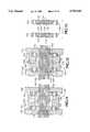
- FIG. 1is an isometric view of a multiconductor percutaneous connector suitable for mounting on bone, which is an embodiment of the present invention.
- FIG. 2is an exploded view showing the two connectable halves of the connector shown in FIG. 1 disconnected from each other, together with a sheet of anisotropic electrical connecting material for use between the connector halves.
- FIG. 3is an exploded view of the percutaneous connector shown in FIG. 1, without the fasteners used to assemble the various parts.
- FIG. 4is a section view of the percutaneous connector shown in FIG. 1, taken along line 4--4 at an enlarged scale.
- FIG. 5is an isometric view of a contact block useful as a part of a connector similar to that shown in FIGS. 1-4.
- FIG. 6is an exploded view showing some of the components of the contact block shown in FIG. 5.
- FIG. 7is a section view taken along line 7--7 of FIG. 5, showing such a contact block at a first stage during the process; of assembly thereof.
- FIG. 8is a view similar to that of FIG. 7 showing a subsequent stage of assembly of such a contact block.
- FIG. 9is a view similar to that of FIG. 7, showing such a contact block upon completion of its assembly and preparation.
- FIG. 10is an exploded view of a pair of collar members aligned with each other and a three-part fixture for assembly of such a pair of contact blocks for use in percutaneous electrical connectors according to the present invention.
- FIG. 11is a section view, taken along line 11--11, of the fixture and collars shown in FIG. 10 assembled together with conductive rods, in a first step of manufacture of a pair of contact blocks in accordance with one method embodying the present invention.
- FIG. 12is a view similar to that of FIG. 11, showing a subsequent stage of preparation of the contact blocks.
- FIG. 13is a section view similar to that of FIG. 11, showing the completed contact blocks prepared in accordance with the method depicted in FIGS. 10-12.
- FIG. 14is a top plan view of a connector embodying the present invention and intended for implantation including attachment to bone tissue located close to the surface of skin tissue.
- FIG. 15is a sectional view of the connector shown in FIG. 14, taken along line 15--15.
- FIG. 16,As a top plan view of a connector which is another embodiment o the present invention and which is particularly adapted for implantation in soft tissue.
- FIG. 17is a sectional view of the connector shown in FIG. 16, taken along line 17--17.
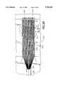
- FIG. 18,is a top plan view of a fixture for use in assembling a cable and connecting its conductors to a contact block of a connector according to the present invention.
- FIG. 19is a sectional side view of the fixture shown in FIG. 18.
- FIG. 20is a top plan view, at an enlarged scale, of a portion of the array of conductors shown in
- FIG. 19together with the contact block and a part of the fixture used to fasten the conductors to it.
- FIG. 21is a view showing the individual electrical conductors of a cable each connected separately to respective terminal ends of conductive rods on the terminal face of the contact block shown in FIGS. 18-20.
- FIG. 22is a view similar to FIG. 18, with the grooved template replaced by a plate having a single groove.
- FIG. 23is view of a person's head in which a percutaneous connector according to the invention has been implanted.
- a percutaneous connector 20intended principally for attachment to bone tissue located close to the surface of the skin of a living mammal, includes an implanted connector half 21 having a lower contact block 22 mounted upon a base 24 adapted to be fastened securely to a surface of bone tissue, initially through the use of fasteners such as screws (not shown) extending through holes 26 defined in arms 28 extending radially from the base 24.
- a sealing layer 30is located between the lower contact block 22 and the base 24, and a biologically implantable multiconductor electrical cable 32 extends away from the base 24 along a ramp 34 extending radially from the base 24 between a pair of the arms 28.
- the cable 32may be attached securely to the distal end of the ramp 34 by a suture 36.
- Such an implanted connector half 21may be attached to such bone tissue so that the connector half 21 extends percutaneously, with an outer skin surface being located with respect to the height of the implanted connector half 21 as indicated by the broken lines 23 in FIG. 1, for example, in a location on a person's skull, as shown in FIG. 23.
- the percutaneous connector 20 shown in FIGS. 1-4 and 20may be attached to a skull of a human, with the conductors 33 of the cable 32 extending to corresponding implanted electrodes intended to transmit electrical impulses to neural tissue, and to receive electrical signals from surrounding neural tissue.
- the cable 32extends subcutaneously away from the connector 20 to a separately prepared opening through the bone tissue giving access to the desired portion of the brain where such electrodes are implanted.
- An upper, or outer, half 40 of the percutaneous connectoris removably connected to the implanted connector half 21 to interconnect the several conductors of a cable 42 to the several conductors of the cable 32, through a layer 44 of elastomeric anisotropically conductive connector material, located between the upper half 40 of the connector and the implanted half 21.
- the upper half 40is removably connected with the implanted half 21 by fasteners such as countersunk socket-headed screws 46 extending through bores 48 defined in the upper half 40 and holes 50 defined through the anisotropically conductive connector layer 44, into threaded bores 52 defined in the lower contact block 22.
- the screws 46thus attach the upper half 40 to the implanted half 21 of the connector with sufficient force to provide reliable electrical interconnection through the layer 44, while they also keep the upper half properly aligned with the implanted connector half 21.
- Tension in the screws 46also produces sufficient pressure between the upper half 40 and the implanted half 21 to prevent moisture from penetrating between the layer 44 and either the upper half 40, or the implanted half 21, of the connector 20.
- fastenerssuch as countersunk socket-headed screws 54 extend through respective bores 56 defined by the lower contact block 22, extending through the lower contact block 22 and the sealing layer 30 into respective threaded bores 58 in the base 24.
- the screws 54are preferably tightened enough to compress the sealing layer 30 slightly, thus helping to exclude moisture such as body fluids from the space between the lower contact block 22 and the base 24.
- the detachable outer or upper half 40 of the connector 20includes a housing 60, which receives an upper contact block 62 within a cavity 64 defined within its interior.
- a cap 66is attached to the housing 60 by a pair of small screws 68 which extend through bores 70 defined through the cap 66 into threaded bores 72 defined in the housing 60, thus retaining the cap 66 properly located and oriented with respect to the housing 60 and the upper contact block 62.
- a lower portion of the upper contact block 62fits closely within an opening 74 which may be of a generally rectangular shape, while a generally circular upper part 75 of the upper contact block 62 acts as a flange to rest upon a shelf 76 defined within the cavity 64 and surrounding the opening 74.
- An opening 78, through which the cable 42 extends,is defined jointly by the cap 66 and housing 60.
- the upper and lower contact blocks 62 and 22each include a respective collar member 80, 82, within which is located a respective matrix 84, 86 locating and securely holding corresponding arrays of conductive rods 88, 90 which extend entirely through each contact block 22 or 62, from a respective mating face 92, 94 to a respective terminal face 96, 98 (FIG. 4).
- the mating faces 92, 94are essentially planar, in this embodiment of the invention, so that the mating surface is relatively easily kept sterile.
- Each of the several conductors 43 of the cable 42is connected electrically with a terminal end 100 of a respective one of the electrically conductive rods 88, and each of the respective conductors 33 of the cable 32 is connected to a respective terminal end 102 of a respective one of the electrically conductive rods 90.
- the form of such electrical connectionmay depend upon the size of the several conductors and of the electrically conductive rods 88, 90.
- a quantity of a suitable curable dielectric material 97, 99 such as an epoxy adhesiveis applied to seal the terminal faces 96, 98 and to provide a stronger mechanical connection of the several conductors respectively to the terminal face 96 or 98.
- Additional sealant materialpreferably of an elastomeric nature such as a UV curable or RTV implantable silicone, may be cast or molded over the epoxy adhesive or other dielectric material 97, 99 to form the sealing layer 30 between the terminal face 98 and the base 24.
- a biologically implantable elastomeric silicone materialwell known as Dow-Corning MDX4-4210 is suitable.
- the epoxy sealant dielectric material 97, 99covers the portions of the various conductors 33, 43 from which individual jackets of insulation have been removed in order to connect the conductors to the terminal ends 100, 102 of the rods 88, 90.
- the sealing dielectric materialelectrically insulates each of the various conductors 33, 43 of the cables 32, 42 from one another and also protects the terminal faces of the contact blocks 22, 62 from intrusion of corrosive or electrolytic fluids to which the connector 20 might be exposed during use.
- the sealing layer 30is made by molding appropriate material in place on the bottom side of the conductors of the cable 32 after electrical connection of the individual conductors of the cable 32 to the lower contact block 22 as will be explained in greater detail below.
- the sealing layer 30is preferably of an elastic silicone material.
- a primer in the form of a low-viscosity liquidis brushed onto the clean surfaces of the dielectric material 99 and of the contact block 22 and the cable 32, where it is allowed to dry as a thin film.
- a mold(not shown) whose interior surfaces are treated with an appropriate release agent is placed over the bottom side of the contact block 22 to form the sealing layer 30 to mate against the base 24 and to have a regular cylindrical side surface 31 and filled with the silicone material of the sealing layer 30.
- the sealing layer 30is cured the mold is removed leaving the sealing layer 30 adhered to the contact block 22.
- Preferred materials for the primerare silane compositions available from United Chemical Technologies, Inc., of Bristol, Pa., as its CAS product numbers M8450 and A0700, either of which is suitable for use as received from the manufacturer.
- the CAS M8450 materialis a 3-mercaptopropylmethyldimethoxysilane, whose molecular formula is C 6 H 18 O 2 SSi.
- the CAS A0700 materialis n-(2-aminoethyl)-3-aminopropylmethyldimethoxysilane whose molecular formula is C 8 H 22 N 2 O 3 Si.
- each conductive rod 88 of the upper contact blockis thus located in direct alignment with a mating end 112 of an electrically conductive rod 90 of the lower contact block 22, with the layer 44 of elastomeric anisotropic connector material located between corresponding ones of the mating ends 110 and the mating ends 112 and electrically interconnecting the corresponding ones of the conductive rods 88 and 90 with each other, thus accomplishing in a small area a large number of electrical interconnections between the individual conductors 33, 43 of the cables 32 and 42.
- the anisotropic connector material of the layer 44may, preferably, be replaced in reconnecting the connector halves.
- the material of the layer 44may be, for example, a curable anisotropically conductive elastomer such as one available from A.I. Technology, Inc., of Princeton, N.J., or from Zymet, Inc. of Hanover, N.J., or anisotropically conductive elastomeric sheet material which is conductive in a direction normal to the major faces of such sheet material, which is available, for example, from Shin-Etsu Polymer of Union City, Calif., as its GB Matrix connector material or its MAF-Connector.
- Such sheet materialconsists of goldplated or nickel-boron plated brass filament fibers embedded at regular spacings within a thin sheet of elastomeric dielectric material such as a silicone rubber.
- the metal fibersare oriented parallel with one another and generally normal to the major plane of the sheet of material, and protrude several microns above the parallel major surfaces 104, 106 of the anisotropically conductive material to contact and interconnect opposed conductors aligned with each other on opposite sides of the connector layer 44.
- a connector sheetmay have a thickness 108 of 0.3 mm (0.008 in), and may include metal filaments whose diameters are approximately 0.04 mm (0.001 inch) in diameter distributed fairly evenly, to provide approximately 40 filaments per square millimeter (25,800 filaments per square inch) passing through the entire thickness of the connector sheet.
- At least the base 24 and the collar 82 of the lower contact block 22are of a biologically inert material, such as titanium, and the surfaces of those elements which are exposed to contact with bone or soft tissue where the connector 20 is implanted are coated, preferably, with a thin layer of glass having a specific composition known by its trademark BIOGLASS.
- a biologically inert materialsuch as titanium
- Such glassis applied in a coating having a thickness of 50 microns to 150 microns total thickness in order to prevent downgrowth of epithelial tissues and to bond with connective tissue.
- a method for applying such a coatinghas been described by West, who teaches use of a boric acid ground coat to which the bioglass coating adheres.
- the bioglass materialmay also be applied by a plasma spraying process which is well known, and which may require more than one layer to achieve the desired thickness.
- the contact block 120includes a matrix 122 of dielectric material surrounding a plurality of electrically conductive rods 124 arranged and held in a predetermined array by a template 126 located within a collar 128.
- An opening 130is defined by the collar 128, and the template 126 fits closely within the opening 128, supported on an inwardly projecting shelf 132 which establishes the proper position of the template 126 between opposite faces 134, 136 of the collar member 128.
- the template 126may be made of a suitable dielectric material such as a ceramic, and defines an array of bores 138 which are preferably parallel with one another and extend directly through the template 126 so as to be oriented normal to the parallel faces 134, 136 of the collar 128 when the template 126 is properly located within the opening 130.
- the contact block 120is prepared by placing a respective electrically conductive rod 124 into each of the several bores 138, which are preferably of a size to receive the rods 124 snugly but slidably. Once the rods 124 have been placed within the bores 138 the template 126 is placed within the opening 130 as shown in FIG. 7, where it is located resting properly against the shelf 132. Thereafter, a quantity of a suitable curable dielectric adhesive sealant material 140, preferably in a viscous liquid form, is inserted to fill the opening 130 and to extend a slight distance outward beyond the respective face 134 or 136 of the collar 128.
- a suitable material for this useis a curable epoxy dielectric material such as Epo-Tek® 301, available from Epoxy Technology, Inc. of Billerica, Mass., as a two-part epoxy adhesive system. The material 140 is then cured by appropriate treatment in accordance with the manufacturer's recommendations.
- thermosetting silicone resinwhich cures to a rigid state, such as that available from NuSil Technology of Carpenteria, Calif., as its product number CF-4721 Thermosetting Silicone Resin. Prior to curing it is a liquid, but with use of 2% by weight of Di-tertbutyl peroxide as a catalyst, and curing for two hours at 177° C. (350° F.) after degassing, it cures to a rigid form and has satisfactory dielectric properties.
- the rods 124 and the surrounding cured adhesive sealant 140are ground and polished with abrasives to form the completed contact block as shown in FIGS. 5 and 9, in which opposite ends of the rods 124 are located on opposite sides of the collar 128 in a predetermined arrangement.
- a planar surface of a mating end 142 of each electrically conductive rod 124is surrounded by a surface of the sealant adhesive 140 as the matrix 122, and the surface of a first or mating face 134 of the contact block 120, the matrix 122 and the included mating ends 142 are all smooth and coplanar.
- the rods 124 and the adhesive sealant material 140are also made smooth and coplanar with the face 136 of the collar 120 as a terminal face of the contact block 120, in which a respective terminal end 144 of each rod 124 is exposed, surrounded by a surface of the matrix 122 of sealant adhesive material 140.
- an additional amount of an adhesive sealantwhich may be the same as the material 140 used to secure the conductive rods 124 in place, is preferably applied as the dielectric material 97, 99 of the connector 20 shown in FIGS. 1-4, to seal these connections at the terminal face of the contact block.
- a biocompatible adhesive elastomersuch as Dow Corning MDX4-4210 is applied to and cured on the terminal face of the contact block as a sealing layer such as the sealing layer 30 of the connector 20 shown in FIGS. 1-4.
- a fixture 148in a slightly different method for preparing the contact blocks such as the lower contact block 22 and upper contact block 62, as shown in FIGS. 10, 11, 12 and 13, a fixture 148 includes a pair of opposite end members 150 and a central member 152 that are aligned with one another. The fixture 148 is used to hold a pair of collars 154 similar to the collar 128 described above, although they need not include the shelf 132 of the collar 128.
- the collars 154are placed between the members 150, 152 of the fixture, aligned with the cavity 156 defined within the central member 152.
- An array of parallel bores 158is provided in each of the end members 150, and the arrays are aligned with each other, with the cavity 156, and with respective openings 160 defined by the collars 154, and the entire assembly is held tightly in this arrangement by a suitable clamp. While the fixture 148 and the collars 154 are thus held securely together, electrically conductive rods 162 are placed through the bores 158 of one of the end members 150 and thence inserted through the openings 160, the cavity 156, and through the corresponding bores 158 in the opposite one of the end members 150 of the fixture to form the arrangement shown in FIG. 11.
- a quantity of a dielectric potting material 170such as a medical grade two-part epoxy system available from Epoxy Technology of Billerica, Mass. under the trade name Epotek 301, is injected within the cavity 156 through the conduit 168, to fill all the available space among the rods 162 within the cavity 156 and the openings 160.
- potting material 170should be introduced carefully, so as not to exert excessive force on the rods 162 and thus bend them.
- the potting material 170is then cured, leaving the fixture and the collars 154 united as a monolithic assembly including the parallel electrically conductive rods 162 extending as an array through each of the openings 160 defined within the collars 154.
- the central member 152 and the portions of the rods 162 extending through the cavity 156 defined by the central member 152are divided into two parts, as by sawing, and the portions of the rods 162 extending beyond either side of each of the collars 154 are machined away, and then smoothed as by use of abrasives and lapidary methods, to produce the parallel mating face 172 and terminal face 174 of each of a pair of similar contact blocks 176 whose mating faces 172 thus include corresponding mating ends 178 each of which was once a part of the same one of the electrically conductive rods 162.
- the end pieces 150 and central member 152 of the fixturemay be manufactured of a suitable plastics material, such as a polycarbonate, by use of conventional injection molding techniques.
- the bores 158 through each of the end members 150may, depending upon the size, be made as a part of the molding process or may be defined later by use of computer-controlled laser machining techniques.
- the matrix of material surrounding the rods 162 within the openings 160may be formed of a ceramic material, or of a glass frit densified by exposure to a suitably high temperature and pressure.
- the fixture 148must be made of material capable of withstanding the temperature used to sinter, fire, or fuse the material of the matrix.
- the fixture 148could be of aluminum, since it can be cast and machined readily and is not too expensive.
- the rods 162 in such a matrixmay be of an alloy having a thermal coefficient of expansion similar to that of glass, such as a nickel-iron alloy including about 29% Ni, 17% Co, 0.3% Mn and the balance being iron, in order to have similar thermal coefficients of expansion, keeping in mind that the resulting greater tendency for contact surfaces to oxidize may make it necessary to gold plate the mating end surfaces 178 to prevent corrosion and maintain low contact resistance.
- an alloy having a thermal coefficient of expansion similar to that of glasssuch as a nickel-iron alloy including about 29% Ni, 17% Co, 0.3% Mn and the balance being iron, in order to have similar thermal coefficients of expansion, keeping in mind that the resulting greater tendency for contact surfaces to oxidize may make it necessary to gold plate the mating end surfaces 178 to prevent corrosion and maintain low contact resistance.
- a percutaneous connector 180includes a generally cylindrical housing 182 which can be attached to a surface of bone tissue in a living body by the use of appropriate screws extending through holes 184 in arms 186 extending radially from the base end 188 of the housing 182.
- the housing 182is preferably coated with an osseointegration- and biointegration-promoting material such as BIOGLASS.
- a cylindrical cavity 190is defined within the housing 182 and a pair of corresponding contact blocks, a lower contact block 192 including conductive rods 193 in a matrix of dielectric material and an upper contact block 194 including similar rods 195, fit snugly within the cavity 190.
- Both of the contact blocks 192 and 194may be generally similar to the contact blocks 120 and 176, for example, and each has a respective mating face 196, 198 including an array of mating ends 224, 226 similar to the mating ends 178 of the contact block 176.
- a cover 200defines a cable port 202 and a cavity 204 beneath the cable port to provide room for connection of the several conductors of a cable to the terminal face 206 of the upper contact block 194, in the same way in which the conductors 43 are attached to the terminal ends 100 of the rods 88 of the contact block 62 (FIG. 4).
- a cable port 212communicates with the cavity 208, extending to the exterior of the housing 182 as a conduit for an implantable cable having connectors individually connected electrically and mechanically to respective terminal ends of conductive rods 193 incorporated in the lower contact block 192.
- the screws 213When the screws 213 are tightened, they squeeze the contact blocks 192 and 194 together, urging the mating faces 196 and 198 against a layer 222 of anisotropic conductive elastomeric connector material located between them to interconnect the respective mating ends 224, 226 of the conductive rods 193 and 195 of the upper and lower contact blocks 192 and 194 with their counterparts, thus interconnecting the corresponding conductors of the cables.
- a percutaneous connector 230is similar in many respects to the connector 180, shown in FIGS. 14 and 15. Like components are designated in FIGS. 16 and 17 by like reference numerals and will not be discussed in detail. The differences are found in the housing 232, which is circular in plan view, with an annular, circular base 234 defining a central cavity 236 which performs as a cable port for a cable (not shown) connected electrically and mechanically with the terminal face 210 of the lower contact block 192.
- the housing 232has an enlarged upper, or outer, end 238 with a rounded shoulder 240, and a concavely rounded neck portion 242 is located between the shoulder 240 and the base 234.
- the housing 232may be made, for example, of a biologically implantable metal such as titanium, or of a biologically inert plastic such as a polytetrafluoroethylene (Teflon), vitreous carbon material, or a polycarbonate material. If the housing 232 is of metal it preferably has a coating of BIOGLASS to promote biointegration, that is, adhesion of the surrounding epithelial and other soft tissue, so that the connector 230 will become integrated with the surrounding tissue in order to resist entrance of microbes into the body along the surfaces of the connector housing 232, and in order to resist marsupialization around the connector 230.
- BIOGLASSto promote biointegration, that is, adhesion of the surrounding epithelial and other soft tissue
- the percutaneous connector 230may be surgically implanted to extend through the skin in the vicinity of a paralyzed muscle, for example, with a cable such as the cable 32 extending from the bottom cavity 236 including conductors 33 leading to electrodes implanted appropriately in the paralyzed muscles.
- the connector 230is implanted with the outer surface 244 of the surrounding skin aligned with the neck 242 of the housing 232, as indicated in FIG. 17.
- a large number of individual conductors 33can be attached to respective terminal ends 102 of conductive rods 90 of the terminal face 98 of a contact block 22 of a connector such the connector 20 in an orderly fashion by use of a fixture 243 including an alignment template 246 to arrange and hold the conductors 33 temporarily while they are individually fastened to the appropriate ones of the terminal ends 102.
- the conductors 33 of a cable 32are placed in respective laser-machined grooves 245 in the template 246, which may be a suitable supported polyimide sheet 125 microns (0.006 inch) thick, for example, to align the several individual conductors 33 and keep them in position side-by-side as a singlelayer array 247.
- the grooves 245are preferably parallel, spaced 94 microns apart, center-to-center.
- Each groove 245is preferably about 50 microns wide and 75 microns deep.
- each conductor 33is individually placed in a required position, as determined, for example, by desired electrode positions for an electrode array 248 where an end of each particular conductor 33 may be retained by use of a vacuum chamber and a perforated matrix to hold an electrode from which a conductor or conductors 33 extend.
- the particular conductor 33is then extended along the fixture 243 and placed in an appropriate one of the grooves 245, and is thence extended further along the fixture 243 across the terminal face 98 of the contact block 22 to the far side of the connector contact block 22, with the distal end 249 of the conductor 33 fastened to the top surface 250 of the fixture 243 by a fast-setting adhesive, such as cyanoacrylic glue.
- Each conductor 33is thus held in tension where it extends along the terminal face 98 of the contact block 22, aligned with a particular one of the terminal ends 102 to which the conductor 33 is to be connected.
- the conductors 33are thus held very close to one another in the single layer array 247, in positions which are maintained while the conductors 33 are prepared and connected to the terminal ends 102 on the contact block 22 in the configuration shown in FIG. 21.
- a single groove 252which may be 2.5 mm. (0.1 inch) wide and 1.5 mm. (0.06 inch) deep, defined in the fixture 243 holds a silicone tube 254 slit lengthwise along one side and held upwardly open.
- Each of the conductors 33is placed within the tube 254 before its distal end 249 is glued down onto the surface 250 of the fixture 243.
- the support block portion 256 of the fixture 243is then removed from the bottom of the fixture to provide room for laser delivery microscope lenses, and a laser is used to remove the parylene-C from the exposed upper side of each conductor 33 of the array 247 over a length of 50-75 microns (0.002-0.003 inch), above the particular one of the terminal ends 102 to which the conductor 33 is to be attached.
- the contact block 22is withdrawn downwardly from beneath the array 247 of the conductors 33.
- the parylene coatingis then removed from the bottom side of each of the conductors 33 of the array 247, in locations corresponding to those where the coating had already been removed from the upper side of each conductor 33.
- the contact block 22is replaced into the fixture 22 and aligned with the array of prepared conductors 33, to permit each conductor 33 to be connected electrically and mechanically to the appropriate terminal end 102.
- attachment of the conductors 33 to the terminal ends 102is accomplished by sonic bonding techniques similar to those used in connecting integrated circuits to chip carriers.
- the terminal ends 102 of the contact block 22are heated, as by conducting heat through the conductive rods of a mating contact block (not shown) held in contact with the downwardly exposed face of the contact block 22.
- a sonic bonderis used to attach the conductors 33 to the respective terminal ends 102.
- the conductors 33Once the conductors 33 have been sonically bonded to the terminal ends 102 of the contact block 22, the distal portions of the conductors 33 are removed, to leave the finished connector contact block 22 as shown in FIG. 21. Thereafter, the sonic bond joints are reinforced by application of the layer of adhesive 99 (FIG. 4), and eventually the sealing layer 30 will be applied in the manner previously described.
- the contact block 22is raised slightly in the fixture 243, lifting the conductors 33 from their positions in the grooves 245 of the template 246, which is then removed from the fixture 243 and replaced by a plate 253 having a groove 255 similar to the groove 252.
- a short length of silicone tubing, also slit along one side and held openis placed into the groove 255, and the portions of the conductors 33 located between the end of the tubing 254 and the contact body 22 are gathered into the short length of tubing.
- Both lengths of the silicone tubing between the electrode array 248 and the contact block 22are allowed to close around the group of conductors 33 and are filled with a silicone such as the DowCorning MDX4-4210 previously mentioned as useful for sealing layer 30.
- the siliconeis then cured, forming a jacket of the cable 32, in which the conductors 33 are embedded, so that the sealing layer 30 can thereafter be applied.
- the cable 42can be connected to the terminal ends 100 of the conductive rods 88 of an upper contact block 62 (FIG. 4) by an analogous procedure.
Landscapes
- Health & Medical Sciences (AREA)
- Engineering & Computer Science (AREA)
- Biomedical Technology (AREA)
- Nuclear Medicine, Radiotherapy & Molecular Imaging (AREA)
- Radiology & Medical Imaging (AREA)
- Life Sciences & Earth Sciences (AREA)
- Animal Behavior & Ethology (AREA)
- General Health & Medical Sciences (AREA)
- Public Health (AREA)
- Veterinary Medicine (AREA)
- Cardiology (AREA)
- Heart & Thoracic Surgery (AREA)
- Electrotherapy Devices (AREA)
- Connector Housings Or Holding Contact Members (AREA)
Abstract
Description
Claims (21)
Priority Applications (1)
| Application Number | Priority Date | Filing Date | Title |
|---|---|---|---|
| US08/779,639US5782645A (en) | 1994-10-18 | 1997-01-07 | Percutaneous connector for multi-conductor electrical cables |
Applications Claiming Priority (2)
| Application Number | Priority Date | Filing Date | Title |
|---|---|---|---|
| US08/326,291US5604976A (en) | 1994-10-18 | 1994-10-18 | Method of making percutaneous connector for multi-conductor electrical cables |
| US08/779,639US5782645A (en) | 1994-10-18 | 1997-01-07 | Percutaneous connector for multi-conductor electrical cables |
Related Parent Applications (1)
| Application Number | Title | Priority Date | Filing Date |
|---|---|---|---|
| US08/326,291DivisionUS5604976A (en) | 1994-10-18 | 1994-10-18 | Method of making percutaneous connector for multi-conductor electrical cables |
Publications (1)
| Publication Number | Publication Date |
|---|---|
| US5782645Atrue US5782645A (en) | 1998-07-21 |
Family
ID=23271607
Family Applications (2)
| Application Number | Title | Priority Date | Filing Date |
|---|---|---|---|
| US08/326,291Expired - LifetimeUS5604976A (en) | 1994-10-18 | 1994-10-18 | Method of making percutaneous connector for multi-conductor electrical cables |
| US08/779,639Expired - LifetimeUS5782645A (en) | 1994-10-18 | 1997-01-07 | Percutaneous connector for multi-conductor electrical cables |
Family Applications Before (1)
| Application Number | Title | Priority Date | Filing Date |
|---|---|---|---|
| US08/326,291Expired - LifetimeUS5604976A (en) | 1994-10-18 | 1994-10-18 | Method of making percutaneous connector for multi-conductor electrical cables |
Country Status (1)
| Country | Link |
|---|---|
| US (2) | US5604976A (en) |
Cited By (59)
| Publication number | Priority date | Publication date | Assignee | Title |
|---|---|---|---|---|
| US6355401B1 (en)* | 1997-11-07 | 2002-03-12 | Intermedics Inc. | Method for preparing a high definition window in a conformally coated medical device |
| US6517476B1 (en) | 2000-05-30 | 2003-02-11 | Otologics Llc | Connector for implantable hearing aid |
| US6524123B2 (en)* | 2001-01-19 | 2003-02-25 | Agilent Technologies, Inc. | Self-aligning, quick-release connector |
| US20040102076A1 (en)* | 2002-11-27 | 2004-05-27 | Jerry Wu | Electrical cable connector assembly |
| US20040111029A1 (en)* | 2002-11-27 | 2004-06-10 | Bates Kenneth N. | Immersible ultrasound probe and cable |
| WO2004089463A3 (en)* | 2003-04-01 | 2005-01-06 | Pierre Sabin | Permanent percutaneous electrical connection device |
| US20050096554A1 (en)* | 2002-11-27 | 2005-05-05 | Dudik Evan M. | Acoustic medical sensor for ultrasound imaging |
| US20050101167A1 (en)* | 1999-12-16 | 2005-05-12 | Weiss Roger E. | Cable connector incorporating anisotropically conductive elastomer |
| US20050165464A1 (en)* | 2004-01-05 | 2005-07-28 | John Parker | Implantable connector |
| WO2005065738A3 (en)* | 2003-12-29 | 2005-08-11 | Cyberkinetics Inc | Transcutaneous implant |
| NL1027450C2 (en)* | 2004-11-09 | 2006-05-10 | Shin Etsu Polymer Europ B V | Interconnection connector, frame comprising such a connector, electrical measuring and testing device and contacting method with the aid of such a connector. |
| WO2007008906A1 (en)* | 2005-07-11 | 2007-01-18 | Boston Scientific Scimed, Inc. | Percutaneous access for neuromodulation procedures |
| US20070128940A1 (en)* | 2003-12-08 | 2007-06-07 | Cochlear Limited | Cochlear implant assembly |
| WO2007104953A1 (en) | 2006-03-13 | 2007-09-20 | Renishaw Plc | Apparatus for fluid delivery with implantable housing openable for providing access to a fluid connector |
| US20080155815A1 (en)* | 2006-08-31 | 2008-07-03 | Yazaki Corporation | Insulator-combining apparatus |
| US20080208289A1 (en)* | 2002-09-30 | 2008-08-28 | Cochlear Limited | Feedthrough for electrical connectors |
| US20080243216A1 (en)* | 2006-10-05 | 2008-10-02 | Yitzhak Zilberman | System and method for percutaneous delivery of electrical stimulation to a target body tissue |
| US20080306387A1 (en)* | 2007-04-13 | 2008-12-11 | Schutz Ronald W | Finger mounted imaging and sensing assembly |
| US20090130885A1 (en)* | 2007-11-15 | 2009-05-21 | Juergen Hagen | Plug connection device designed to connect two function elements for signal and power transmission |
| US20090149036A1 (en)* | 2005-07-27 | 2009-06-11 | Kang Lee | Inherently sealed electrical connector |
| US20090187233A1 (en)* | 2008-01-18 | 2009-07-23 | Stracener Steve W | Connector for implantable hearing aid |
| US20090326602A1 (en)* | 2008-06-27 | 2009-12-31 | Arkady Glukhovsky | Treatment of indications using electrical stimulation |
| US20100016929A1 (en)* | 2004-01-22 | 2010-01-21 | Arthur Prochazka | Method and system for controlled nerve ablation |
| US20100042070A1 (en)* | 2006-11-23 | 2010-02-18 | Renishaw Plc | Neurological apparatus comprising a percutaneous access device |
| US20100198298A1 (en)* | 2005-06-28 | 2010-08-05 | Arkady Glukhovsky | Implant system and method using implanted passive conductors for routing electrical current |
| US7837479B1 (en)* | 2009-07-16 | 2010-11-23 | Tyco Electronics Corporation | Mezzanine connector assembly having coated contacts |
| US20100326723A1 (en)* | 2007-07-17 | 2010-12-30 | Cochlear Limited | Electrically insulative structure having holes for feedthroughs |
| US20100326701A1 (en)* | 2009-06-29 | 2010-12-30 | Boston Scientific Neuromodulation Corporation | Systems and methods for removing insulation disposed over conductors of implantable electric stimulation systems |
| US20110298304A1 (en)* | 2010-06-07 | 2011-12-08 | Thoratec Corporation | Bi-ventricular percutaneous cable |
| US20120045918A1 (en)* | 2009-04-23 | 2012-02-23 | Pierre-Yves Litzler | Subcutaneous device for electrical percutaneous connection |
| US20120302959A1 (en)* | 2010-02-12 | 2012-11-29 | Renishaw (Ireland) Limited | Percutaneous drug delivery apparatus |
| US20120315774A1 (en)* | 2011-02-18 | 2012-12-13 | Willis Williams | Flex to flex connection device |
| US8406886B2 (en) | 2004-01-22 | 2013-03-26 | Rehabtronics, Inc. | Method of routing electrical current to bodily tissues via implanted passive conductors |
| WO2013048396A1 (en)* | 2011-09-28 | 2013-04-04 | Advanced Bionics Ag | Modular biomedical implants |
| AU2012200660B2 (en)* | 2006-10-05 | 2013-09-05 | Bioness Inc. | System and method for percutaneous delivery of electrical stimulation to a target body tissue |
| US8639353B2 (en) | 2009-04-23 | 2014-01-28 | Centre Hospitalier Universitaire De Rouen | Electrical connection device implantable in the human body |
| US20140030921A1 (en)* | 2011-03-31 | 2014-01-30 | Yazaki Corporation | Shielded connector |
| US20140128951A1 (en)* | 2012-11-07 | 2014-05-08 | The Florida International University Board Of Trustees | Modular Multi-Channel Inline Connector System |
| US20150065786A1 (en)* | 2013-09-03 | 2015-03-05 | Nupulse, Inc. | Skin interface device for cardiac assist device |
| US9153900B2 (en) | 2011-10-14 | 2015-10-06 | Biomet Manufacturing Corp. | Implantable subcutaneous electrical socket and percutaneous plug |
| US20150320991A1 (en)* | 2012-06-28 | 2015-11-12 | Plugmed Heart | Percutaneous connection device with a socket and with an extension member |
| US20160006160A1 (en)* | 2014-07-03 | 2016-01-07 | Electronic Motion Systems Holding Limited | Sealed connector and method of sealing a connector |
| US20170093070A1 (en)* | 2015-09-30 | 2017-03-30 | Apple Inc. | Hidden electrical contacts |
| EP3027259A4 (en)* | 2013-07-31 | 2017-04-05 | Alcyone Lifesciences, Inc. | Systems and methods for drug delivery, treatment, and monitoring |
| US9647386B2 (en) | 2014-06-12 | 2017-05-09 | Heartware, Inc. | Percutaneous connector and associated methods of use |
| US9662484B2 (en) | 2012-10-02 | 2017-05-30 | Renishaw Plc | Neurosurgical device and method |
| WO2017151779A1 (en)* | 2016-03-02 | 2017-09-08 | Heartware, Inc. | Skin button with flat cable |
| WO2017178007A1 (en)* | 2016-04-12 | 2017-10-19 | HARTING Electronics GmbH | Plug connector with a conductive rubber element |
| US9919129B2 (en) | 2012-12-18 | 2018-03-20 | Alcyone Lifesciences, Inc. | Systems and methods for reducing or preventing backflow in a delivery system |
| WO2018157214A1 (en)* | 2017-03-02 | 2018-09-07 | Saluda Medical Pty Limited | Electrode assembly |
| US10137244B2 (en) | 2011-08-01 | 2018-11-27 | Alcyone Lifesciences, Inc. | Microfluidic drug delivery devices with venturi effect |
| US10149980B2 (en)* | 2015-06-24 | 2018-12-11 | Lawrence Livermore National Security, Llc | System and method for implantable electrical connector |
| US10251722B1 (en)* | 2018-09-17 | 2019-04-09 | The Florida International University Board Of Trustees | Stereotaxic brain implant system for large animals |
| US10456533B2 (en) | 2013-06-17 | 2019-10-29 | Alcyone Lifesciences, Inc. | Methods and devices for protecting catheter tips and stereotactic fixtures for microcatheters |
| US10531882B2 (en) | 2016-01-04 | 2020-01-14 | Alcyone Lifesciences, Inc. | Methods and devices for treating stroke |
| US10806396B2 (en) | 2015-01-26 | 2020-10-20 | Alcyone Lifesciences, Inc. | Drug delivery methods with tracer |
| US11058871B2 (en) | 2003-12-08 | 2021-07-13 | Cochlear Limited | Manufacturing an electrode array for a stimulating medical device |
| US11684768B2 (en) | 2016-08-24 | 2023-06-27 | Nupulsecv, Inc. | Blood pump assembly and method of use thereof |
| US12156978B2 (en) | 2019-05-17 | 2024-12-03 | Nupulsecv, Inc. | Intravascularly delivered blood pumps and associated devices, systems, and methods |
Families Citing this family (14)
| Publication number | Priority date | Publication date | Assignee | Title |
|---|---|---|---|---|
| US5833655A (en)* | 1997-05-15 | 1998-11-10 | L. Vad Technology, Inc. | Percutaneous access device having removable turret assembly |
| US5990380A (en)* | 1997-10-10 | 1999-11-23 | University Of Florida Research Foundation, Inc. | Percutaneous biofixed medical implants |
| SE513670C2 (en) | 1997-12-18 | 2000-10-16 | Grogrunden Ab Nr 444 | Percutaneous bone anchored transducer |
| NZ501422A (en)* | 1998-06-03 | 2003-01-31 | Neurocontrol Corp | Intramuscular stimulation system comprising a plurality of implantable electrodes in combination with a portable device equipped with a memorised set of movements for eliciting a series of muscle responses to prevent muscle atrophy |
| US6401334B1 (en) | 1999-02-18 | 2002-06-11 | Intermedics Ind. | Apparatus for laser stripping coated cables for endocardial defibrillation leads and method of manufacture of such leads |
| US6368147B1 (en)* | 2000-03-02 | 2002-04-09 | Microhelix, Inc. | Zero insertion force percutaneous connector and flexible brain probe assembly |
| US6817905B2 (en)* | 2000-06-20 | 2004-11-16 | Medtronic, Inc. | Connector assembly for an implantable medical device and process for making |
| US20070087637A1 (en)* | 2004-10-15 | 2007-04-19 | Zart Bryan J | Connector assembly for an implantable medical device and process for making |
| JP4220880B2 (en)* | 2003-10-17 | 2009-02-04 | 住友重機械工業株式会社 | Waterproof terminal block unit |
| AU2009293506B2 (en) | 2008-09-17 | 2015-10-22 | Saluda Medical Pty Limited | Knitted electrode assembly and integrated connector for an active implantable medical device |
| CN104379034B (en)* | 2012-10-26 | 2018-12-25 | 皇家飞利浦有限公司 | Machine for preparing drink including at least one pipe for conveying liquid |
| US20160003270A1 (en)* | 2013-03-15 | 2016-01-07 | L. Christopher Franklin | Mounting apparatus |
| US10343626B2 (en)* | 2015-03-25 | 2019-07-09 | Daiwa Kasei Industry Co., Ltd. | Method for manufacturing wire harness |
| USD1091833S1 (en)* | 2023-07-25 | 2025-09-02 | Christopher Childress | Epidermal anchor |
Citations (17)
| Publication number | Priority date | Publication date | Assignee | Title |
|---|---|---|---|---|
| US3277421A (en)* | 1963-08-30 | 1966-10-04 | Walton Products Inc | Automatic electric coupler |
| US3409864A (en)* | 1965-09-23 | 1968-11-05 | Amp Inc | Sealed electrical connecting device |
| US3447161A (en)* | 1966-08-01 | 1969-06-03 | Avco Corp | Disinfectant dispensing percutaneous connector |
| US3924916A (en)* | 1974-02-19 | 1975-12-09 | A & P Products Inc | Connector adapter |
| US3995644A (en)* | 1975-09-16 | 1976-12-07 | The United States Of America As Represented By The Administrator Of The National Aeronautics And Space Administration | Percutaneous connector device |
| US4025964A (en)* | 1976-07-30 | 1977-05-31 | The United States Of America As Represented By The Administrator Of The National Aeronautics And Space Administration | Magnetic electrical connectors for biomedical percutaneous implants |
| US4209481A (en)* | 1976-04-19 | 1980-06-24 | Toray Industries, Inc. | Process for producing an anisotropically electroconductive sheet |
| US4434134A (en)* | 1981-04-10 | 1984-02-28 | International Business Machines Corporation | Pinned ceramic substrate |
| US4516820A (en)* | 1983-01-27 | 1985-05-14 | The Commonwealth Of Australia | Cochlear prosthesis package connector |
| US4645504A (en)* | 1985-05-24 | 1987-02-24 | The Regents Of The University Of California | Implantable infection barrier seal and method |
| US4686765A (en)* | 1984-05-03 | 1987-08-18 | Regents Of The University Of California | Method for making an intracochlear electrode array |
| US4819647A (en)* | 1984-05-03 | 1989-04-11 | The Regents Of The University Of California | Intracochlear electrode array |
| JPH0197382A (en)* | 1987-10-09 | 1989-04-14 | Shin Etsu Polymer Co Ltd | Anisotropic conductive connector and its manufacture |
| US4875870A (en)* | 1987-07-16 | 1989-10-24 | Raychem Limited | Article for protecting a substrate |
| USRE33170E (en)* | 1982-03-26 | 1990-02-27 | The Regents Of The University Of California | Surgically implantable disconnect device |
| US5026397A (en)* | 1983-03-24 | 1991-06-25 | Kabushiki Kaisya Advance Kaihatsu Kenkyujo | Transcutaneously implantable element |
| US5274917A (en)* | 1992-06-08 | 1994-01-04 | The Whitaker Corporation | Method of making connector with monolithic multi-contact array |
- 1994
- 1994-10-18USUS08/326,291patent/US5604976A/ennot_activeExpired - Lifetime
- 1997
- 1997-01-07USUS08/779,639patent/US5782645A/ennot_activeExpired - Lifetime
Patent Citations (18)
| Publication number | Priority date | Publication date | Assignee | Title |
|---|---|---|---|---|
| US3277421A (en)* | 1963-08-30 | 1966-10-04 | Walton Products Inc | Automatic electric coupler |
| US3409864A (en)* | 1965-09-23 | 1968-11-05 | Amp Inc | Sealed electrical connecting device |
| US3447161A (en)* | 1966-08-01 | 1969-06-03 | Avco Corp | Disinfectant dispensing percutaneous connector |
| US3924916A (en)* | 1974-02-19 | 1975-12-09 | A & P Products Inc | Connector adapter |
| US3995644A (en)* | 1975-09-16 | 1976-12-07 | The United States Of America As Represented By The Administrator Of The National Aeronautics And Space Administration | Percutaneous connector device |
| US4209481A (en)* | 1976-04-19 | 1980-06-24 | Toray Industries, Inc. | Process for producing an anisotropically electroconductive sheet |
| US4025964A (en)* | 1976-07-30 | 1977-05-31 | The United States Of America As Represented By The Administrator Of The National Aeronautics And Space Administration | Magnetic electrical connectors for biomedical percutaneous implants |
| US4434134A (en)* | 1981-04-10 | 1984-02-28 | International Business Machines Corporation | Pinned ceramic substrate |
| USRE33170E (en)* | 1982-03-26 | 1990-02-27 | The Regents Of The University Of California | Surgically implantable disconnect device |
| US4516820A (en)* | 1983-01-27 | 1985-05-14 | The Commonwealth Of Australia | Cochlear prosthesis package connector |
| US5026397A (en)* | 1983-03-24 | 1991-06-25 | Kabushiki Kaisya Advance Kaihatsu Kenkyujo | Transcutaneously implantable element |
| US5035711A (en)* | 1983-03-24 | 1991-07-30 | Kabushiki Kaisya Advance Kaihatsu Kenkyujo | Transcutaneously implantable element |
| US4686765A (en)* | 1984-05-03 | 1987-08-18 | Regents Of The University Of California | Method for making an intracochlear electrode array |
| US4819647A (en)* | 1984-05-03 | 1989-04-11 | The Regents Of The University Of California | Intracochlear electrode array |
| US4645504A (en)* | 1985-05-24 | 1987-02-24 | The Regents Of The University Of California | Implantable infection barrier seal and method |
| US4875870A (en)* | 1987-07-16 | 1989-10-24 | Raychem Limited | Article for protecting a substrate |
| JPH0197382A (en)* | 1987-10-09 | 1989-04-14 | Shin Etsu Polymer Co Ltd | Anisotropic conductive connector and its manufacture |
| US5274917A (en)* | 1992-06-08 | 1994-01-04 | The Whitaker Corporation | Method of making connector with monolithic multi-contact array |
Non-Patent Citations (15)
| Title |
|---|
| Akazawa et al., "Functional Neuromuscular Stimulation System Using an Implantable Hydroxyapatite Connector and a Microprocessor-Based Portable Stimulator," IEEE Transactions of Biomedical Engineering, vol. 36, No. 7, 1989. |
| Akazawa et al., Functional Neuromuscular Stimulation System Using an Implantable Hydroxyapatite Connector and a Microprocessor Based Portable Stimulator, IEEE Transactions of Biomedical Engineering, vol. 36, No. 7, 1989.* |
| Chehroudi et al., "The role of connective tissue in inhibiting epithelial downgrowth on titanium-coated percutaneous implants," 1992. |
| Chehroudi et al., The role of connective tissue in inhibiting epithelial downgrowth on titanium coated percutaneous implants, 1992.* |
| Jansen et al., "Tissue response to percutaneous implants in rabbits," Journal of Biomedical Materials Research, vol. 24, pp. 295-307, 1990. |
| Jansen et al., Tissue response to percutaneous implants in rabbits, Journal of Biomedical Materials Research, vol. 24, pp. 295 307, 1990.* |
| Klomp et al., Percutaneous Connections in Man, Transactions, American Society for Artificial Organs, vol. XXV, 1979.* |
| Poole Warren et al., In Vivo Response to Ceramic Percutaneous Implants, Bioceramics, vol. 4, pp. 187 190, 1991.* |
| Poole-Warren et al., "In Vivo Response to Ceramic Percutaneous Implants," Bioceramics, vol. 4, pp. 187-190, 1991. |
| Tsuji et al., "Implantation in the Human Forearm of a Percutaneous Device Made of Sintered Hydroxylapatite," CRC Handbook of Bioactive Ceramics, vol. II, pp. 373-376, earlier than Oct. 18, 1993. |
| Tsuji et al., Implantation in the Human Forearm of a Percutaneous Device Made of Sintered Hydroxylapatite, CRC Handbook of Bioactive Ceramics, vol. II, pp. 373 376, earlier than Oct. 18, 1993.* |
| West et al., "In Vivo Bone-Bonding Study of Bioglass®-Coated Titanium Alloy," CRC Handbook of Bioactive Ceramics, vol. I, pp. 161-166, earlier than Oct. 18, 1993. |
| West et al., In Vivo Bone Bonding Study of Bioglass Coated Titanium Alloy, CRC Handbook of Bioactive Ceramics, vol. I, pp. 161 166, earlier than Oct. 18, 1993.* |
| Yoshiyama et al., "Hydroxylapatite Percutaneous Access Device in Peritoneal Dialysis," CRC Handbook of Bioactive Ceramics, vol. II, pp. 377-385, earlier than Oct. 18, 1993. |
| Yoshiyama et al., Hydroxylapatite Percutaneous Access Device in Peritoneal Dialysis, CRC Handbook of Bioactive Ceramics, vol. II, pp. 377 385, earlier than Oct. 18, 1993.* |
Cited By (131)
| Publication number | Priority date | Publication date | Assignee | Title |
|---|---|---|---|---|
| US6355401B1 (en)* | 1997-11-07 | 2002-03-12 | Intermedics Inc. | Method for preparing a high definition window in a conformally coated medical device |
| US7223105B2 (en)* | 1999-12-16 | 2007-05-29 | Paricon Technologies Corporation | Cable connector incorporating anisotropically conductive elastomer |
| US20050101167A1 (en)* | 1999-12-16 | 2005-05-12 | Weiss Roger E. | Cable connector incorporating anisotropically conductive elastomer |
| US6517476B1 (en) | 2000-05-30 | 2003-02-11 | Otologics Llc | Connector for implantable hearing aid |
| US6524123B2 (en)* | 2001-01-19 | 2003-02-25 | Agilent Technologies, Inc. | Self-aligning, quick-release connector |
| US6751856B2 (en) | 2001-01-19 | 2004-06-22 | Agilent Technologies, Inc. | Method for electrically connecting a circuit board connector to an external device |
| US7996982B2 (en) | 2002-09-30 | 2011-08-16 | Cochlear Limited | Method of making feedthroughs for electrical connectors |
| US20080209723A1 (en)* | 2002-09-30 | 2008-09-04 | Cochlear Limited | Feedthrough for electrical connectors |
| AU2011201190B2 (en)* | 2002-09-30 | 2013-01-17 | Cochlear Limited | Feedthrough for electrical connectors |
| US7988507B2 (en)* | 2002-09-30 | 2011-08-02 | Cochlear Limited | Feedthrough for electrical connectors |
| US20080208289A1 (en)* | 2002-09-30 | 2008-08-28 | Cochlear Limited | Feedthrough for electrical connectors |
| US8211026B2 (en) | 2002-11-27 | 2012-07-03 | Blacktoe Medical Iii, Inc. | Finger mounted probe adapted for intraoperative use |
| US20050096554A1 (en)* | 2002-11-27 | 2005-05-05 | Dudik Evan M. | Acoustic medical sensor for ultrasound imaging |
| US6821140B2 (en)* | 2002-11-27 | 2004-11-23 | Hon Hai Precision Ind. Co., Ltd. | Electrical cable connector assembly |
| US7297115B2 (en) | 2002-11-27 | 2007-11-20 | Black Toe Medical Iii, Inc. | Immersible ultrasound probe and cable |
| US20040111029A1 (en)* | 2002-11-27 | 2004-06-10 | Bates Kenneth N. | Immersible ultrasound probe and cable |
| US20040102076A1 (en)* | 2002-11-27 | 2004-05-27 | Jerry Wu | Electrical cable connector assembly |
| WO2004089463A3 (en)* | 2003-04-01 | 2005-01-06 | Pierre Sabin | Permanent percutaneous electrical connection device |
| US20110230944A1 (en)* | 2003-12-08 | 2011-09-22 | Andy Ho | Implantable antenna |
| US7950134B2 (en) | 2003-12-08 | 2011-05-31 | Cochlear Limited | Implantable antenna |
| US11058871B2 (en) | 2003-12-08 | 2021-07-13 | Cochlear Limited | Manufacturing an electrode array for a stimulating medical device |
| US20070128940A1 (en)* | 2003-12-08 | 2007-06-07 | Cochlear Limited | Cochlear implant assembly |
| US8819919B2 (en) | 2003-12-08 | 2014-09-02 | Cochlear Limited | Method of forming a non-linear path of an electrically conducting wire |
| US20050283203A1 (en)* | 2003-12-29 | 2005-12-22 | Flaherty J C | Transcutaneous implant |
| US7647097B2 (en) | 2003-12-29 | 2010-01-12 | Braingate Co., Llc | Transcutaneous implant |
| WO2005065738A3 (en)* | 2003-12-29 | 2005-08-11 | Cyberkinetics Inc | Transcutaneous implant |
| US20050165464A1 (en)* | 2004-01-05 | 2005-07-28 | John Parker | Implantable connector |
| US7534127B2 (en)* | 2004-01-05 | 2009-05-19 | Cochlear Limited | Implantable connector |
| US9072886B2 (en) | 2004-01-22 | 2015-07-07 | Rehabtronics, Inc. | Method of routing electrical current to bodily tissues via implanted passive conductors |
| US8406886B2 (en) | 2004-01-22 | 2013-03-26 | Rehabtronics, Inc. | Method of routing electrical current to bodily tissues via implanted passive conductors |
| US20100016929A1 (en)* | 2004-01-22 | 2010-01-21 | Arthur Prochazka | Method and system for controlled nerve ablation |
| NL1027450C2 (en)* | 2004-11-09 | 2006-05-10 | Shin Etsu Polymer Europ B V | Interconnection connector, frame comprising such a connector, electrical measuring and testing device and contacting method with the aid of such a connector. |
| EP1655808A1 (en)* | 2004-11-09 | 2006-05-10 | Shin-Etsu Polymer Europe B.V. | Contactor, frame comprising such a contactor, electrical measuring and testing apparatus and method of contacting by means of such a contactor |
| US8862225B2 (en) | 2005-06-28 | 2014-10-14 | Bioness Inc. | Implant, system and method using implanted passive conductors for routing electrical current |
| US20100198298A1 (en)* | 2005-06-28 | 2010-08-05 | Arkady Glukhovsky | Implant system and method using implanted passive conductors for routing electrical current |
| US8538517B2 (en) | 2005-06-28 | 2013-09-17 | Bioness Inc. | Implant, system and method using implanted passive conductors for routing electrical current |
| US8332029B2 (en) | 2005-06-28 | 2012-12-11 | Bioness Inc. | Implant system and method using implanted passive conductors for routing electrical current |
| US7415309B2 (en) | 2005-07-11 | 2008-08-19 | Boston Scientific Scimed, Inc. | Percutaneous access for neuromodulation procedures |
| WO2007008906A1 (en)* | 2005-07-11 | 2007-01-18 | Boston Scientific Scimed, Inc. | Percutaneous access for neuromodulation procedures |
| US20070038263A1 (en)* | 2005-07-11 | 2007-02-15 | Mcintyre Jon T | Percutaneous access for neuromodulation procedures |
| US20090149036A1 (en)* | 2005-07-27 | 2009-06-11 | Kang Lee | Inherently sealed electrical connector |
| US7731517B2 (en)* | 2005-07-27 | 2010-06-08 | Physical Optics Corporation | Inherently sealed electrical connector |
| CN101400386B (en)* | 2006-03-13 | 2012-12-05 | 瑞尼斯豪(爱尔兰)有限公司 | Apparatus for fluid delivery with implantable housing openable for providing access to a fluid connector |
| WO2007104953A1 (en) | 2006-03-13 | 2007-09-20 | Renishaw Plc | Apparatus for fluid delivery with implantable housing openable for providing access to a fluid connector |
| US20090030373A1 (en)* | 2006-03-13 | 2009-01-29 | Renishaw Plc | Method and Apparatus for Fluid Delivery |
| US10518075B2 (en) | 2006-03-13 | 2019-12-31 | Renishaw Plc | Method and apparatus for fluid delivery |
| US9132265B2 (en) | 2006-03-13 | 2015-09-15 | Renishaw (Ireland) Limited | Method and apparatus for fluid delivery |
| US8747371B2 (en) | 2006-03-13 | 2014-06-10 | Renishaw Plc | Method and apparatus for fluid delivery |
| US7665203B2 (en)* | 2006-08-31 | 2010-02-23 | Yazaki Corporation | Insulator-combining apparatus |
| US20080155815A1 (en)* | 2006-08-31 | 2008-07-03 | Yazaki Corporation | Insulator-combining apparatus |
| AU2007303034B2 (en)* | 2006-10-05 | 2011-11-10 | Bioness Inc. | System and method for percutaneous delivery of electrical stimulation to a target body tissue |
| US8483820B2 (en) | 2006-10-05 | 2013-07-09 | Bioness Inc. | System and method for percutaneous delivery of electrical stimulation to a target body tissue |
| US20080243216A1 (en)* | 2006-10-05 | 2008-10-02 | Yitzhak Zilberman | System and method for percutaneous delivery of electrical stimulation to a target body tissue |
| AU2012200660B2 (en)* | 2006-10-05 | 2013-09-05 | Bioness Inc. | System and method for percutaneous delivery of electrical stimulation to a target body tissue |
| US20100042070A1 (en)* | 2006-11-23 | 2010-02-18 | Renishaw Plc | Neurological apparatus comprising a percutaneous access device |
| US11717663B2 (en) | 2006-11-23 | 2023-08-08 | Renishaw (Ireland) Limited | Neurological apparatus comprising a percutaneous access device |
| US8974422B2 (en) | 2006-11-23 | 2015-03-10 | Renishaw (Ireland) Limited | Neurological apparatus comprising a percutaneous access device |
| US10751520B2 (en) | 2006-11-23 | 2020-08-25 | Renishaw (Ireland) Limited | Neurological apparatus comprising a percutaneous access device |
| US20080306387A1 (en)* | 2007-04-13 | 2008-12-11 | Schutz Ronald W | Finger mounted imaging and sensing assembly |
| US20100326723A1 (en)* | 2007-07-17 | 2010-12-30 | Cochlear Limited | Electrically insulative structure having holes for feedthroughs |
| US8672667B2 (en) | 2007-07-17 | 2014-03-18 | Cochlear Limited | Electrically insulative structure having holes for feedthroughs |
| US7722375B2 (en)* | 2007-11-15 | 2010-05-25 | Siemens Aktiengesellschaft | Plug connection device designed to connect two function elements for signal and power transmission |
| US20090130885A1 (en)* | 2007-11-15 | 2009-05-21 | Juergen Hagen | Plug connection device designed to connect two function elements for signal and power transmission |
| US7822479B2 (en) | 2008-01-18 | 2010-10-26 | Otologics, Llc | Connector for implantable hearing aid |
| US20090187233A1 (en)* | 2008-01-18 | 2009-07-23 | Stracener Steve W | Connector for implantable hearing aid |
| US20090326602A1 (en)* | 2008-06-27 | 2009-12-31 | Arkady Glukhovsky | Treatment of indications using electrical stimulation |
| US9925374B2 (en) | 2008-06-27 | 2018-03-27 | Bioness Inc. | Treatment of indications using electrical stimulation |
| US8545255B2 (en)* | 2009-04-23 | 2013-10-01 | Centre Hospitalier Universitaire De Rouen | Subcutaneous device for electrical percutaneous connection |
| US20120045918A1 (en)* | 2009-04-23 | 2012-02-23 | Pierre-Yves Litzler | Subcutaneous device for electrical percutaneous connection |
| US8639353B2 (en) | 2009-04-23 | 2014-01-28 | Centre Hospitalier Universitaire De Rouen | Electrical connection device implantable in the human body |
| US20100326701A1 (en)* | 2009-06-29 | 2010-12-30 | Boston Scientific Neuromodulation Corporation | Systems and methods for removing insulation disposed over conductors of implantable electric stimulation systems |
| US8322026B2 (en) | 2009-06-29 | 2012-12-04 | Boston Scientific Neuromodulation Corporation | Method for forming a lead |
| US8857048B2 (en) | 2009-06-29 | 2014-10-14 | Boston Scientific Neuromodulation Corporation | System for separating conductors |
| US7837479B1 (en)* | 2009-07-16 | 2010-11-23 | Tyco Electronics Corporation | Mezzanine connector assembly having coated contacts |
| US10596362B2 (en) | 2010-02-12 | 2020-03-24 | Renishaw (Ireland) Limited | Percutaneous drug delivery apparatus |
| US8827987B2 (en)* | 2010-02-12 | 2014-09-09 | Renishaw (Ireland) Limited | Percutaneous drug delivery apparatus |
| US10507316B2 (en) | 2010-02-12 | 2019-12-17 | Renishaw (Ireland) Limited | Implantable fluid router |
| US20120302959A1 (en)* | 2010-02-12 | 2012-11-29 | Renishaw (Ireland) Limited | Percutaneous drug delivery apparatus |
| US11826536B2 (en) | 2010-02-12 | 2023-11-28 | Renishaw (Ireland) Limited | Percutaneous drug delivery apparatus |
| US8668526B2 (en) | 2010-06-07 | 2014-03-11 | Thoratec Corporation | Bi-ventricular percutaneous cable |
| US20110298304A1 (en)* | 2010-06-07 | 2011-12-08 | Thoratec Corporation | Bi-ventricular percutaneous cable |
| US8388384B2 (en)* | 2010-06-07 | 2013-03-05 | Thoratec Corporation | Bi-ventricular percutaneous cable |
| US8529277B2 (en)* | 2011-02-18 | 2013-09-10 | Hi Rel Connectors, Inc | Flex to flex connection device |
| US9093801B2 (en)* | 2011-02-18 | 2015-07-28 | Hi Rel Connectors, Inc. | Flex to flex connection device |
| US20120315774A1 (en)* | 2011-02-18 | 2012-12-13 | Willis Williams | Flex to flex connection device |
| US20140256193A1 (en)* | 2011-02-18 | 2014-09-11 | Hi Rel Connectors, Inc. | Flex to flex connection device |
| US20130323945A1 (en)* | 2011-02-18 | 2013-12-05 | Hi Rel Connectors, Inc | Flex to flex connection device |
| US8668503B2 (en)* | 2011-02-18 | 2014-03-11 | Hi Rel Connectors, Inc | Flex to flex connection device |
| US8992249B2 (en)* | 2011-03-31 | 2015-03-31 | Yazaki Corporation | Shielded connector |
| US20140030921A1 (en)* | 2011-03-31 | 2014-01-30 | Yazaki Corporation | Shielded connector |
| US10434251B2 (en) | 2011-08-01 | 2019-10-08 | Alcyone Lifesciences, Inc. | Multi-directional microfluidic drug delivery device |
| US10137244B2 (en) | 2011-08-01 | 2018-11-27 | Alcyone Lifesciences, Inc. | Microfluidic drug delivery devices with venturi effect |
| WO2013048396A1 (en)* | 2011-09-28 | 2013-04-04 | Advanced Bionics Ag | Modular biomedical implants |
| US9511216B2 (en) | 2011-09-28 | 2016-12-06 | Advanced Bionics Ag | Modular biomedical implants |
| US9153900B2 (en) | 2011-10-14 | 2015-10-06 | Biomet Manufacturing Corp. | Implantable subcutaneous electrical socket and percutaneous plug |
| US20150320991A1 (en)* | 2012-06-28 | 2015-11-12 | Plugmed Heart | Percutaneous connection device with a socket and with an extension member |
| US10220197B2 (en)* | 2012-06-28 | 2019-03-05 | Plugmed Heart | Percutaneous connection device with a socket and with an extension member |
| US9662484B2 (en) | 2012-10-02 | 2017-05-30 | Renishaw Plc | Neurosurgical device and method |
| US9427565B2 (en)* | 2012-11-07 | 2016-08-30 | The Florida International University Board Of Trustees | Modular multi-channel inline connector system |
| US20140128951A1 (en)* | 2012-11-07 | 2014-05-08 | The Florida International University Board Of Trustees | Modular Multi-Channel Inline Connector System |
| US11213653B2 (en) | 2012-12-18 | 2022-01-04 | Alcyone Lifesciences, Inc. | Systems and methods for reducing or preventing backflow in a delivery system |
| US9919129B2 (en) | 2012-12-18 | 2018-03-20 | Alcyone Lifesciences, Inc. | Systems and methods for reducing or preventing backflow in a delivery system |
| US11260201B2 (en) | 2012-12-18 | 2022-03-01 | Alcyone Lifesciences, Inc. | Systems and methods for reducing or preventing backflow in a delivery system |
| US10065016B2 (en) | 2012-12-18 | 2018-09-04 | Alcyone Lifesciences, Inc. | Systems and methods for reducing or preventing backflow in a delivery system |
| US10363394B2 (en) | 2012-12-18 | 2019-07-30 | Alcyone Lifesciences, Inc. | Systems and methods for reducing or preventing backflow in a delivery system |
| US10456533B2 (en) | 2013-06-17 | 2019-10-29 | Alcyone Lifesciences, Inc. | Methods and devices for protecting catheter tips and stereotactic fixtures for microcatheters |
| US11602375B2 (en) | 2013-06-17 | 2023-03-14 | Alcyone Therapeutics, Inc. | Methods and devices for protecting catheter tips and stereotactic fixtures for microcatheters |
| US10441770B2 (en) | 2013-07-31 | 2019-10-15 | Alcyone Lifesciences, Inc. | Systems and methods for drug delivery, treatment, and monitoring |
| US11534592B2 (en) | 2013-07-31 | 2022-12-27 | Alcyone Therapeutics, Inc. | Systems and methods for drug delivery, treatment, and monitoring |
| EP3027259A4 (en)* | 2013-07-31 | 2017-04-05 | Alcyone Lifesciences, Inc. | Systems and methods for drug delivery, treatment, and monitoring |
| US9265871B2 (en)* | 2013-09-03 | 2016-02-23 | Nupulse, Inc. | Skin interface device for cardiac assist device |
| US20150065786A1 (en)* | 2013-09-03 | 2015-03-05 | Nupulse, Inc. | Skin interface device for cardiac assist device |
| US9592328B2 (en) | 2013-09-03 | 2017-03-14 | Nupulse, Inc. | Skin interface device for cardiac assist device |
| US9647386B2 (en) | 2014-06-12 | 2017-05-09 | Heartware, Inc. | Percutaneous connector and associated methods of use |
| US20160006160A1 (en)* | 2014-07-03 | 2016-01-07 | Electronic Motion Systems Holding Limited | Sealed connector and method of sealing a connector |
| US10806396B2 (en) | 2015-01-26 | 2020-10-20 | Alcyone Lifesciences, Inc. | Drug delivery methods with tracer |
| US10149980B2 (en)* | 2015-06-24 | 2018-12-11 | Lawrence Livermore National Security, Llc | System and method for implantable electrical connector |
| US20170093070A1 (en)* | 2015-09-30 | 2017-03-30 | Apple Inc. | Hidden electrical contacts |
| US9780474B2 (en)* | 2015-09-30 | 2017-10-03 | Apple Inc. | Hidden electrical contacts |
| US10531882B2 (en) | 2016-01-04 | 2020-01-14 | Alcyone Lifesciences, Inc. | Methods and devices for treating stroke |
| CN109152873A (en)* | 2016-03-02 | 2019-01-04 | 心脏器械股份有限公司 | skin button with flat cable |
| WO2017151779A1 (en)* | 2016-03-02 | 2017-09-08 | Heartware, Inc. | Skin button with flat cable |
| US10186352B2 (en) | 2016-03-02 | 2019-01-22 | Medtronic HeartWare, Inc. | Skin button with flat cable |
| US10460857B2 (en) | 2016-03-02 | 2019-10-29 | Heartware, Inc. | Skin button with flat cable |
| US11189950B2 (en) | 2016-04-12 | 2021-11-30 | HARTING Electronics GmbH | Plug connector with a conductive rubber element |
| WO2017178007A1 (en)* | 2016-04-12 | 2017-10-19 | HARTING Electronics GmbH | Plug connector with a conductive rubber element |
| US11684768B2 (en) | 2016-08-24 | 2023-06-27 | Nupulsecv, Inc. | Blood pump assembly and method of use thereof |
| US11129980B2 (en) | 2017-03-02 | 2021-09-28 | Saluda Medical Pty Limited | Electrode assembly |
| WO2018157214A1 (en)* | 2017-03-02 | 2018-09-07 | Saluda Medical Pty Limited | Electrode assembly |
| US10251722B1 (en)* | 2018-09-17 | 2019-04-09 | The Florida International University Board Of Trustees | Stereotaxic brain implant system for large animals |
| US12156978B2 (en) | 2019-05-17 | 2024-12-03 | Nupulsecv, Inc. | Intravascularly delivered blood pumps and associated devices, systems, and methods |
Also Published As
| Publication number | Publication date |
|---|---|
| US5604976A (en) | 1997-02-25 |
Similar Documents
| Publication | Publication Date | Title |
|---|---|---|
| US5782645A (en) | Percutaneous connector for multi-conductor electrical cables | |
| US4686765A (en) | Method for making an intracochlear electrode array | |
| US4819647A (en) | Intracochlear electrode array | |
| US10355438B2 (en) | Implantable medical devices including elongated conductor bodies that facilitate device and lead configuration variants | |
| US8412330B2 (en) | Connector assemblies for implantable medical electrical systems | |
| CN109152873B (en) | Skin button with flat cable | |
| US4516820A (en) | Cochlear prosthesis package connector | |
| US7035692B1 (en) | High density polymer-based integrated electrode array | |
| US6198969B1 (en) | Implantable connector for multi-output neurostimulators | |
| US8206180B1 (en) | Connector assemblies and contacts for implantable medical electrical systems | |
| Loeb et al. | Design and fabrication of an experimental cochlear prosthesis | |
| US5070605A (en) | Method for making an in-line pacemaker connector system | |
| US4898173A (en) | In-line pacemaker connector system | |
| AU657332B2 (en) | Percutaneous connector | |
| US7596408B2 (en) | Implantable medical device with anti-infection agent | |
| US9263172B2 (en) | Wire constructs | |
| KR101911561B1 (en) | Helical core ear implant electrode | |
| US9162072B2 (en) | Implantable medical device with lubricious material | |
| US20050107858A1 (en) | Implantable electrical cable and method of making | |
| US20020198582A1 (en) | Implantable devices having a liquid crystal polymer substrate | |
| JPH10502552A (en) | Soft artificial neural plate | |
| US20060047322A1 (en) | Electrical conductive path for a medical electronics device | |
| US10608354B2 (en) | Implantable connector with two electrical components | |
| CN103002945A (en) | Insulated electrical connection in an implantable medical device | |
| US3089483A (en) | Multiple electrode holders for indicating nerve responses to stimulation |
Legal Events
| Date | Code | Title | Description |
|---|---|---|---|
| STCF | Information on status: patent grant | Free format text:PATENTED CASE | |
| AS | Assignment | Owner name:BIOELECTRIC CORPORATION, OREGON Free format text:CHANGE OF NAME;ASSIGNOR:PI MEDICAL CORPORATION;REEL/FRAME:009328/0134 Effective date:19980702 | |
| CC | Certificate of correction | ||
| AS | Assignment | Owner name:MHL DEVELOPMENT COMPANY, INC., OREGON Free format text:ASSIGNMENT OF ASSIGNORS INTEREST;ASSIGNOR:BIOELECTRIC CORP.;REEL/FRAME:011461/0879 Effective date:20001228 | |
| AS | Assignment | Owner name:IMPERIAL BANK, CALIFORNIA Free format text:SECURITY INTEREST;ASSIGNOR:MHL DEVELOPMENT COMPANY, THE SUCCESSOR IN INTEREST TO GRAYSCALE, INC., BIOELECTRIC CORPORATION AND MICROHELIX LABS, INC.;REEL/FRAME:011511/0016 Effective date:20010105 | |
| FEPP | Fee payment procedure | Free format text:PAYOR NUMBER ASSIGNED (ORIGINAL EVENT CODE: ASPN); ENTITY STATUS OF PATENT OWNER: LARGE ENTITY | |
| REFU | Refund | Free format text:REFUND - 3.5 YR SURCHARGE - LATE PMT W/IN 6 MO, SMALL ENTITY (ORIGINAL EVENT CODE: R286); ENTITY STATUS OF PATENT OWNER: LARGE ENTITY | |
| FPAY | Fee payment | Year of fee payment:4 | |
| REMI | Maintenance fee reminder mailed | ||
| AS | Assignment | Owner name:MICROHELIX, INC., OREGON Free format text:CHANGE OF NAME;ASSIGNOR:MHL DEVELOPMENT COMPANY, INC.;REEL/FRAME:013447/0398 Effective date:20010302 | |
| AS | Assignment | Owner name:SASS, RICHARD G., OREGON Free format text:SECURITY AGREEMENT;ASSIGNOR:MICROHELIX, INC.;REEL/FRAME:014022/0696 Effective date:20020228 | |
| AS | Assignment | Owner name:MHL DEVELOPMENT COMPANY, OREGON Free format text:RELEASE OF SECURITY INTEREST;ASSIGNOR:IMPERIAL BANK;REEL/FRAME:015156/0183 Effective date:20040311 | |
| AS | Assignment | Owner name:ADVANCED NEUROMODULATION SYSTEMS, INC., TEXAS Free format text:ASSIGNMENT OF ASSIGNORS INTEREST;ASSIGNOR:MICROHELIX, INC.;REEL/FRAME:014601/0477 Effective date:20040421 | |
| FEPP | Fee payment procedure | Free format text:PAT HOLDER NO LONGER CLAIMS SMALL ENTITY STATUS, ENTITY STATUS SET TO UNDISCOUNTED (ORIGINAL EVENT CODE: STOL); ENTITY STATUS OF PATENT OWNER: LARGE ENTITY | |
| REFU | Refund | Free format text:REFUND - PAYMENT OF MAINTENANCE FEE, 8TH YR, SMALL ENTITY (ORIGINAL EVENT CODE: R2552); ENTITY STATUS OF PATENT OWNER: LARGE ENTITY | |
| FPAY | Fee payment | Year of fee payment:8 | |
| FEPP | Fee payment procedure | Free format text:ENTITY STATUS SET TO UNDISCOUNTED (ORIGINAL EVENT CODE: BIG.); ENTITY STATUS OF PATENT OWNER: LARGE ENTITY | |
| FPAY | Fee payment | Year of fee payment:12 |