US5781876A - Cruise control road speed control device, especially for a diesel-powered vehicle - Google Patents
Cruise control road speed control device, especially for a diesel-powered vehicleDownload PDFInfo
- Publication number
- US5781876A US5781876AUS08/552,875US55287595AUS5781876AUS 5781876 AUS5781876 AUS 5781876AUS 55287595 AUS55287595 AUS 55287595AUS 5781876 AUS5781876 AUS 5781876A
- Authority
- US
- United States
- Prior art keywords
- signal
- input signal
- speed
- control
- injection volume
- Prior art date
- Legal status (The legal status is an assumption and is not a legal conclusion. Google has not performed a legal analysis and makes no representation as to the accuracy of the status listed.)
- Expired - Fee Related
Links
Images
Classifications
- B—PERFORMING OPERATIONS; TRANSPORTING
- B60—VEHICLES IN GENERAL
- B60K—ARRANGEMENT OR MOUNTING OF PROPULSION UNITS OR OF TRANSMISSIONS IN VEHICLES; ARRANGEMENT OR MOUNTING OF PLURAL DIVERSE PRIME-MOVERS IN VEHICLES; AUXILIARY DRIVES FOR VEHICLES; INSTRUMENTATION OR DASHBOARDS FOR VEHICLES; ARRANGEMENTS IN CONNECTION WITH COOLING, AIR INTAKE, GAS EXHAUST OR FUEL SUPPLY OF PROPULSION UNITS IN VEHICLES
- B60K31/00—Vehicle fittings, acting on a single sub-unit only, for automatically controlling vehicle speed, i.e. preventing speed from exceeding an arbitrarily established velocity or maintaining speed at a particular velocity, as selected by the vehicle operator
- B60K31/02—Vehicle fittings, acting on a single sub-unit only, for automatically controlling vehicle speed, i.e. preventing speed from exceeding an arbitrarily established velocity or maintaining speed at a particular velocity, as selected by the vehicle operator including electrically actuated servomechanism
- B60K31/04—Vehicle fittings, acting on a single sub-unit only, for automatically controlling vehicle speed, i.e. preventing speed from exceeding an arbitrarily established velocity or maintaining speed at a particular velocity, as selected by the vehicle operator including electrically actuated servomechanism and means for comparing one electrical quantity, e.g. voltage, pulse, waveform, flux, or the like, with another quantity of a like kind, which comparison means is involved in the development of an electrical signal which is fed into the controlling means
- B60K31/042—Vehicle fittings, acting on a single sub-unit only, for automatically controlling vehicle speed, i.e. preventing speed from exceeding an arbitrarily established velocity or maintaining speed at a particular velocity, as selected by the vehicle operator including electrically actuated servomechanism and means for comparing one electrical quantity, e.g. voltage, pulse, waveform, flux, or the like, with another quantity of a like kind, which comparison means is involved in the development of an electrical signal which is fed into the controlling means where at least one electrical quantity is set by the vehicle operator
- F—MECHANICAL ENGINEERING; LIGHTING; HEATING; WEAPONS; BLASTING
- F02—COMBUSTION ENGINES; HOT-GAS OR COMBUSTION-PRODUCT ENGINE PLANTS
- F02D—CONTROLLING COMBUSTION ENGINES
- F02D31/00—Use of speed-sensing governors to control combustion engines, not otherwise provided for
- F02D31/001—Electric control of rotation speed
- F02D31/007—Electric control of rotation speed controlling fuel supply
- B—PERFORMING OPERATIONS; TRANSPORTING
- B60—VEHICLES IN GENERAL
- B60W—CONJOINT CONTROL OF VEHICLE SUB-UNITS OF DIFFERENT TYPE OR DIFFERENT FUNCTION; CONTROL SYSTEMS SPECIALLY ADAPTED FOR HYBRID VEHICLES; ROAD VEHICLE DRIVE CONTROL SYSTEMS FOR PURPOSES NOT RELATED TO THE CONTROL OF A PARTICULAR SUB-UNIT
- B60W2710/00—Output or target parameters relating to a particular sub-units
- B60W2710/06—Combustion engines, Gas turbines
- B60W2710/0605—Throttle position
Definitions
- the inventionrelates to a road speed control device in the form of a so-called cruise control for a motor vehicle having an internal combustion engine.
- the cruise controlincludes a speed controller and an adjusting element connected downstream for adjusting the amount of fuel to be injected.
- a road speed controller of this kind for a commercial motor vehicleis described for example in the article "Elektronisches Gaspedal fur Nutzfastel” Electronic Accelerator for Commercial Vehicles!, Automobiltechnische Zeitschrift 95 (1993) 2, page 80, by G. Gils and A. Vokan.
- Cruise control systemsare electrical devices for controlling vehicle speed. They are activated on demand by the driver, usually through the use of a cruise control operating lever provided for that purpose. Following activation, cruise control always begins at the load point set by the accelerator, i.e. with the corresponding volume of fuel injected in order for control to proceed without jerking or delay.
- the operating modes “set and accelerate,” “set and decelerate,” and “resume”can be set using the operating lever, with the vehicle speed changing in the desired manner during the operation of the operating lever and with the actual speed being established as the set speed for cruise control when the lever is released.
- the cruise controltypically contains a PDT 1 control, whose output signal is fed to the input of the device that adjusts the volume of fuel injected.
- U.S. Pat. No. 4,374,422describes a road speed control device for commercial vehicles in which signals are subtracted from an amplified speed deviation signal which, at high rates of change in deviation or throttle motion, are established and decrease exponentially. This subtraction of the additional signals is intended to limit the control response and to stabilize control.
- German Patent document DE 28 16 613 A1describes a cruise control road speed control device in which the output signal of an acceleration control, wired in parallel with the speed controller, is subtracted from the output signal of the speed controller.
- the actuating signal thus formedis supplied first to a downstream actuator and second through a high-pass filter to the acceleration control with feedback.
- the acceleration controlis intended to produce an improvement in the dynamic control behavior such that the desired set speed is reached more rapidly with changes in the actual speed.
- High-pass feedbackis intended to ensure that changes in the set speed can be supplied to the actuator with a delay.
- German Patent document DE 26 54 455 A1describes a device for regulating the road speed of a motor vehicle, in which an actual speed signal and a set speed signal are supplied to the input of a speed controller.
- the speed controllerdelivers a controller output signal dependent thereon.
- the controller output signalis supplied to a throttle positioning member through a so-called Miller integrator stage, which causes any change in the controller output signal up to a predetermined amplitude to be passed on without delay or with a slight delay and to be delayed above this value.
- the impeller and turbine wheelsAt maximum engine rpm, the impeller and turbine wheels have approximately the same rpm, while during acceleration the turbine wheel is entrained by a hydraulic fluid by the rotation of the impeller. Between these two extreme states, consequently, there is a so-called slip range which reflects the difference in rpm between the impeller and turbine wheel and becomes narrower as engine rpm increases.
- the functions of the impeller and turbine wheelare reversed with poorer efficiency so that the slip range increases in contrast to normal operation with acceleration.
- the width of the converter slip rangecan be 1000 rpm or more.
- the-engine rpmis in the range of high converter slip.
- the engineis required to deliver little or no forward torque in order to maintain speed so that the engine rpm drops without this involving a decrease in speed.
- the decrease in rpmbecause of the injection volume characteristic map, results in a further decrease in the volume injected, which in turn results in the actual speed dropping slightly below the set speed.
- the cruise controldelivers a signal that increases the volume injected, but because of converter slip this is initially felt only as an increase in rpm and not in speed.
- the cruise controlalready has an output value that is too high, which results in a positive speed deviation, which triggers a subsequent counter-control by the cruise control. Therefore, the injection volume characteristic map with its rpm evaluation and the slip range of the transmission torque converter result in a direct feedback effect that favors oscillations in engine rpm.
- the instabilities in rpm that initially make themselves felt only acoustically and opticallycan build up and be felt as juddering of the vehicle.
- a cruise control road speed control devicefor a motor vehicle with an internal combustion engine, especially a Diesel engine, including a speed control, a fuel injection volume adjusting member, and an attenuating member.
- the speed controlreceives on the input side an actual speed signal and a set speed signal and delivers at an output a controller output signal that depends on these input signals.
- the fuel injection volume adjusting memberon the basis of a preset injection volume characteristic map, delivers an injection volume control signal as a function of an input signal supplied to an input.
- the attenuating memberis connected on the input side with the output of the speed control and on the output side with the input of the fuel injection volume adjusting member and delivers an output signal which is smaller, in a lower input signal value range, than its input signal.
- the attenuating memberBy providing the attenuating member, a reduction in control amplification is actually achieved at low engine loads in the rpm range that is sensitive to rpm oscillations.
- the attenuation of the control output signal that is produced by the attenuating member in the lower value rangecounteracts the amplification of the cruise control's control output signal in the lower value range that is produced by the usual design of the injection volume characteristic map, in which, instead, cruise control value changes up to a factor of three are amplified by the injection volume characteristic map.
- cruise control value changes up to a factor of threeare amplified by the injection volume characteristic map.
- the attenuating membercan be used in connection with any type of speed control and can consequently be used with great versatility for damping rpm oscillations in cruise controls.
- the measure according to the present inventionalso does not require, for the required constant functional ability, relatively expensive smooth adjustments of the control parameters to reduce the control amplification.
- no additional parameters such as engine rpmneed to be processed to apply the device, and the injection volume characteristic map can be designed wholly on the basis of the engine standpoint without taking cruise control requirements into account.
- the attenuating memberconverts the control output signal into a signal that corresponds to the latter in an upper value range of the controller output signal.
- the control output signalis smaller by a factor than the controller output signal which decreases monotonically from the value of one with a decreasing controller output signal so that the actual cruise control signal is attenuated very effectively in the low value range, that is, it is especially sensitive to rpm oscillations and consequently effectively opposes rpm oscillation.
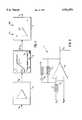
- FIG. 1is a block diagram of the part of a cruise control road speed control device according to the invention for a motor vehicle with electronic Diesel fuel control and automatic transmission;
- FIG. 2is a block diagram of the cruise control circuit used in FIG. 1.
- the cruise control device in FIG. 1includes a conventional analog control as the speed controller 1, an attenuating member 2 connected downstream therefrom, to which the output signal U A from the speed controller 1 is supplied on the input side, as well as a fuel injection volume adjusting member 3 that receives the output signal (k.U A ) from the attenuating member 2.
- the attenuating member 3delivers a corresponding injection volume control signal S E at its output.
- the structure of the speed controller 1is shown in greater detail in FIG. 2.
- the speed controller 1consists of an operational amplifier 4, to whose non-inverting input the set speed signal v soll is applied and to whose inverting input the actual speed signal v ist is applied through a resistor 7. This results in the control deviation signal U E on the input side of the operational amplifier 4. Control output signal U A then appears at the output of the operational amplifier 4.
- the output of the operational amplifieris fed back to the inverting operational amplifier input through a parallel circuit, one branch of which consists of a resistor 5 and the other branch consists of a series circuit composed of a resistor 6 and a capacitor 8.
- the speed controller 1 with this designhas a control response to a normalized set point step change, which consists of a static P amplification in the steady control state that is reached after a controller time constant has elapsed and of an instantaneous dynamic P amplification which typically amounts to 25% to 60% of the static P amplification.
- the control amplificationrises from the instantaneous dynamic amplification value to the static amplification value within the controller time constant according to an exponential function.
- the fuel injection volume adjusting member 3generates the injection volume control signal SE for an actuator, located downstream and not shown, as a function of input values that are supplied on the basis of a previously supplied injection volume characteristic map EK (indicated only schematically in the corresponding functional block of FIG. 1), as is usual for electronic Diesel fuel injection systems.
- the low input signal valuesare significantly amplified by the design of the injection volume characteristic map EK, for example in the range of less than 15% of the maximum input signal.
- attenuating member 2is connected in the loop between the speed control 1 and the fuel injection volume adjusting member 3.
- the fuel injection volume adjusting member 3receives engine rpm information Md as well as accelerator position information Fs as input parameters, with the accelerator position value having no influence as long as the attenuating member 2 delivers an output signal (k.U A ) which is larger.
- Attenuating member 2multiplies the controller output signal U A supplied on the input side by a factor of k to produce the output signal (k.U A ) which is supplied as an input signal to fuel injection volume adjusting member 3.
- Multiplication factor kis determined by a characteristic as shown in the function block of attenuating member 2 in FIG. 1. The factor k depends on the input signal, i.e. the controller output signal U A , constantly assuming the value of one in an upper value range B2 between approximately 42% and 100% of the maximum controller output signal U AM . In this upper input signal value range B2 of the controller output signal U A , the latter is consequently passed unchanged by the attenuating member 2 to the fuel injection volume adjusting member 3 as a control signal.
- the multiplication factor kthen constantly decreases monotonically with decreasing input signal U A until it reaches its minimum value k m which is, for example approximately 0.25, at the minimum value zero of input signal U A .
- the exact response in this lower input signal value range B1 of controller output signal U A in which attenuation factor k remains less than one,can be determined empirically for example depending on the application. To save on memory locations, this response can be predetermined by a few supporting points with linear interpolation between them.
- the minimum value k m of factor kas well as the position of the cutoff point between the lower value range B1 and the upper input signal value range B2 of the controller output signal U A can be chosen appropriately.
- the location of the attenuating member according to the invention between the cruise control and the fuel injection volume adjusting memberpermits effective damping of rpm oscillations during cruise control operation with a low engine load, with the cruise control being of conventional design without any changes being required in the cruise control itself
Landscapes
- Engineering & Computer Science (AREA)
- Chemical & Material Sciences (AREA)
- Combustion & Propulsion (AREA)
- Mechanical Engineering (AREA)
- General Engineering & Computer Science (AREA)
- Transportation (AREA)
- Electrical Control Of Air Or Fuel Supplied To Internal-Combustion Engine (AREA)
- Control Of Vehicle Engines Or Engines For Specific Uses (AREA)
- Controls For Constant Speed Travelling (AREA)
Abstract
Description
Claims (5)
Applications Claiming Priority (2)
| Application Number | Priority Date | Filing Date | Title |
|---|---|---|---|
| DE4439424ADE4439424C1 (en) | 1994-11-04 | 1994-11-04 | Cruise control device for diesel vehicle |
| DE4439424.1 | 1994-11-04 |
Publications (1)
| Publication Number | Publication Date |
|---|---|
| US5781876Atrue US5781876A (en) | 1998-07-14 |
Family
ID=6532478
Family Applications (1)
| Application Number | Title | Priority Date | Filing Date |
|---|---|---|---|
| US08/552,875Expired - Fee RelatedUS5781876A (en) | 1994-11-04 | 1995-11-03 | Cruise control road speed control device, especially for a diesel-powered vehicle |
Country Status (3)
| Country | Link |
|---|---|
| US (1) | US5781876A (en) |
| DE (1) | DE4439424C1 (en) |
| FR (1) | FR2726515B1 (en) |
Cited By (5)
| Publication number | Priority date | Publication date | Assignee | Title |
|---|---|---|---|---|
| US5992551A (en)* | 1995-12-30 | 1999-11-30 | Robert Bosch Gmbh | Method and arrangement for controlling and limiting the speed of a vehicle |
| US6032645A (en)* | 1998-02-24 | 2000-03-07 | Isuzo Motors Limited | Electronic fuel injection apparatus for diesel engine |
| WO2000055487A1 (en)* | 1999-03-15 | 2000-09-21 | Aerosance, Inc. | Automatic aircraft engine fuel mixture optimization |
| US20020056310A1 (en)* | 1997-04-23 | 2002-05-16 | Denso Corporation | Control method for gas concentration sensor |
| US20030126845A1 (en)* | 2002-01-10 | 2003-07-10 | New Holland North America, Inc. | Combine power selection system |
Families Citing this family (5)
| Publication number | Priority date | Publication date | Assignee | Title |
|---|---|---|---|---|
| DE19820830C1 (en) | 1998-05-09 | 1999-09-23 | Daimler Chrysler Ag | Vehicle motor control device with speed control or regulation |
| DE19821481C2 (en)* | 1998-05-14 | 2003-07-17 | Iav Gmbh | Method and device for controlling a motor vehicle drive unit with an internal combustion engine and CVT transmission |
| DE19924862C1 (en) | 1999-05-31 | 2000-08-31 | Daimler Chrysler Ag | Method for adjusting a preset target speed in a vehicle with a steady rate of fuel operates one branch for full operating of fuel with all cylinders firing and another branch for partial cut-out with a portion of cylinders firing |
| DE10049167A1 (en)* | 2000-09-27 | 2002-01-03 | Siemens Ag | Setting driving speed of vehicle with direct injection internal combustion engine involves different control parameters determining fuel and/or air feed for different engine operating modes |
| DE102013224985A1 (en) | 2013-12-05 | 2015-06-11 | Robert Bosch Gmbh | Modular speed control device for a motor vehicle |
Citations (15)
| Publication number | Priority date | Publication date | Assignee | Title |
|---|---|---|---|---|
| DE2654455A1 (en)* | 1976-12-01 | 1978-06-08 | Vdo Schindling | DEVICE FOR REGULATING THE SPEED OF A MOTOR VEHICLE |
| US4170274A (en)* | 1976-09-23 | 1979-10-09 | VDO, Adolf Schindling AG | Device for regulating the traveling speed of a motor vehicle |
| DE2816613A1 (en)* | 1978-04-17 | 1979-10-25 | Vdo Adolf Schindling A | DEVICE FOR REGULATING THE SPEED OF A MOTOR VEHICLE |
| US4374422A (en)* | 1980-10-27 | 1983-02-15 | The Bendix Corporation | Automatic speed control for heavy vehicles |
| US4422420A (en)* | 1981-09-24 | 1983-12-27 | Trw Inc. | Method and apparatus for fuel control in fuel injected internal combustion engines |
| US4561517A (en)* | 1980-11-04 | 1985-12-31 | Return On Investment Corporation | Cruise control modulator |
| US4976239A (en)* | 1984-02-07 | 1990-12-11 | Nissan Motor Company, Limited | Throttle control system with noise-free accelerator position input |
| US5019986A (en)* | 1990-04-27 | 1991-05-28 | Caterpillar Inc. | Method of operating a vehicle engine |
| US5062404A (en)* | 1989-04-17 | 1991-11-05 | Lucas Industries Public Limited Company | Engine throttle control system |
| US5129475A (en)* | 1988-09-20 | 1992-07-14 | Mitsubishi Jidosha Kogyo Kabushiki Kaisha | Cruise control device for motor vehicles |
| US5201296A (en)* | 1992-03-30 | 1993-04-13 | Caterpillar Inc. | Control system for an internal combustion engine |
| US5234071A (en)* | 1991-02-26 | 1993-08-10 | Mitsubishi Denki Kabushiki Kaisha | Travel control apparatus for motor a vehicle |
| US5311063A (en)* | 1989-06-05 | 1994-05-10 | Hubler Corporation | Automatic load speed controller for engine governor |
| US5357912A (en)* | 1993-02-26 | 1994-10-25 | Caterpillar Inc. | Electronic control system and method for a hydraulically-actuated fuel injection system |
| US5393277A (en)* | 1993-10-12 | 1995-02-28 | Cummins Electronics Company, Inc. | Variable electronically controlled shift points for a cruise control system |
- 1994
- 1994-11-04DEDE4439424Apatent/DE4439424C1/ennot_activeExpired - Fee Related
- 1995
- 1995-11-02FRFR9512924Apatent/FR2726515B1/ennot_activeExpired - Fee Related
- 1995-11-03USUS08/552,875patent/US5781876A/ennot_activeExpired - Fee Related
Patent Citations (16)
| Publication number | Priority date | Publication date | Assignee | Title |
|---|---|---|---|---|
| US4170274A (en)* | 1976-09-23 | 1979-10-09 | VDO, Adolf Schindling AG | Device for regulating the traveling speed of a motor vehicle |
| US4157126A (en)* | 1976-12-01 | 1979-06-05 | Harald Collonia | System for regulating the traveling speed of a motor vehicle |
| DE2654455A1 (en)* | 1976-12-01 | 1978-06-08 | Vdo Schindling | DEVICE FOR REGULATING THE SPEED OF A MOTOR VEHICLE |
| DE2816613A1 (en)* | 1978-04-17 | 1979-10-25 | Vdo Adolf Schindling A | DEVICE FOR REGULATING THE SPEED OF A MOTOR VEHICLE |
| US4374422A (en)* | 1980-10-27 | 1983-02-15 | The Bendix Corporation | Automatic speed control for heavy vehicles |
| US4561517A (en)* | 1980-11-04 | 1985-12-31 | Return On Investment Corporation | Cruise control modulator |
| US4422420A (en)* | 1981-09-24 | 1983-12-27 | Trw Inc. | Method and apparatus for fuel control in fuel injected internal combustion engines |
| US4976239A (en)* | 1984-02-07 | 1990-12-11 | Nissan Motor Company, Limited | Throttle control system with noise-free accelerator position input |
| US5129475A (en)* | 1988-09-20 | 1992-07-14 | Mitsubishi Jidosha Kogyo Kabushiki Kaisha | Cruise control device for motor vehicles |
| US5062404A (en)* | 1989-04-17 | 1991-11-05 | Lucas Industries Public Limited Company | Engine throttle control system |
| US5311063A (en)* | 1989-06-05 | 1994-05-10 | Hubler Corporation | Automatic load speed controller for engine governor |
| US5019986A (en)* | 1990-04-27 | 1991-05-28 | Caterpillar Inc. | Method of operating a vehicle engine |
| US5234071A (en)* | 1991-02-26 | 1993-08-10 | Mitsubishi Denki Kabushiki Kaisha | Travel control apparatus for motor a vehicle |
| US5201296A (en)* | 1992-03-30 | 1993-04-13 | Caterpillar Inc. | Control system for an internal combustion engine |
| US5357912A (en)* | 1993-02-26 | 1994-10-25 | Caterpillar Inc. | Electronic control system and method for a hydraulically-actuated fuel injection system |
| US5393277A (en)* | 1993-10-12 | 1995-02-28 | Cummins Electronics Company, Inc. | Variable electronically controlled shift points for a cruise control system |
Non-Patent Citations (2)
| Title |
|---|
| Article entitled "Elektronisches Gaspedal fur Nutzfahrzeuge" (Electronic Accelerator for Commercial Vehicles), Automobiltechnische Zeitschrift 95 (1993) 2, p. 80, by G. Gils and A. Vokan. |
| Article entitled Elektronisches Gaspedal f u r Nutzfahrzeuge (Electronic Accelerator for Commercial Vehicles), Automobiltechnische Zeitschrift 95 (1993) 2, p. 80, by G. Gils and A. Vokan.* |
Cited By (7)
| Publication number | Priority date | Publication date | Assignee | Title |
|---|---|---|---|---|
| US5992551A (en)* | 1995-12-30 | 1999-11-30 | Robert Bosch Gmbh | Method and arrangement for controlling and limiting the speed of a vehicle |
| US20020056310A1 (en)* | 1997-04-23 | 2002-05-16 | Denso Corporation | Control method for gas concentration sensor |
| US6032645A (en)* | 1998-02-24 | 2000-03-07 | Isuzo Motors Limited | Electronic fuel injection apparatus for diesel engine |
| WO2000055487A1 (en)* | 1999-03-15 | 2000-09-21 | Aerosance, Inc. | Automatic aircraft engine fuel mixture optimization |
| US6317680B1 (en)* | 1999-03-15 | 2001-11-13 | Aerosance, Inc. | Automatic aircraft engine fuel mixture optimization |
| US20030126845A1 (en)* | 2002-01-10 | 2003-07-10 | New Holland North America, Inc. | Combine power selection system |
| US6865870B2 (en)* | 2002-01-10 | 2005-03-15 | Cnh America Llc | Combine power selection system |
Also Published As
| Publication number | Publication date |
|---|---|
| DE4439424C1 (en) | 1996-01-04 |
| FR2726515B1 (en) | 1998-07-31 |
| FR2726515A1 (en) | 1996-05-10 |
Similar Documents
| Publication | Publication Date | Title |
|---|---|---|
| US4281567A (en) | System for optimizing the fuel consumption of an internal combustion engine | |
| US5514050A (en) | Method for operating a motor vehicle having a continuously variable transmission by continuously changing the transmission ratio or detecting if a braking operation is present and continuously adjusting the transmission | |
| US4311123A (en) | Method and apparatus for controlling the fuel supply of an internal combustion engine | |
| US5392215A (en) | Automatic cruising speed controller for an automotive vehicle | |
| JP2750071B2 (en) | Variable power drivetrain engine control method and system | |
| US6405587B1 (en) | System and method of controlling the coastdown of a vehicle | |
| US5628706A (en) | Method and arrangement for controlling the output power of a drive unit of a motor vehicle | |
| JPS63270950A (en) | Driving slip preventive method and device | |
| US5781876A (en) | Cruise control road speed control device, especially for a diesel-powered vehicle | |
| KR20040044444A (en) | Anti-slip control method for a clutch | |
| US4852429A (en) | Method and apparatus for controlling the steplessly variable transmission ratio of a continuously variable transmission, especially of a cone disk belt transmission, in a motor vehicle | |
| US6061623A (en) | Method and system for pre-positioning wheel torque in a torque based vehicle speed control | |
| JPH0530980B2 (en) | ||
| US5323746A (en) | Governor | |
| JP2002532053A (en) | Driving method and apparatus for vehicle drive unit | |
| US5313855A (en) | System for the open-loop control of a motor vehicle | |
| US4825991A (en) | Control system for a clutch for a vehicle | |
| EP1065364B1 (en) | Engine management system with torque limit override means | |
| WO1989007709A1 (en) | Diesel engine governor with anti-judder device | |
| JPH02274636A (en) | Constant speed running device for vehicle | |
| US6205394B1 (en) | Automatic engine power control system for motor vehicles having a power control element | |
| JP2780448B2 (en) | Transmission control device for continuously variable transmission | |
| JPS6233093B2 (en) | ||
| JP2808160B2 (en) | Line pressure control device for automatic transmission | |
| JP3323819B2 (en) | Air conditioner control method |
Legal Events
| Date | Code | Title | Description |
|---|---|---|---|
| AS | Assignment | Owner name:MERCEDES-BENZ AG, GERMANY Free format text:ASSIGNMENT OF ASSIGNORS INTEREST;ASSIGNOR:SAUR, JOERG;REEL/FRAME:007767/0441 Effective date:19951009 | |
| FEPP | Fee payment procedure | Free format text:PAYOR NUMBER ASSIGNED (ORIGINAL EVENT CODE: ASPN); ENTITY STATUS OF PATENT OWNER: LARGE ENTITY | |
| AS | Assignment | Owner name:DAIMLER-BENZ AKTIENGESELLSCHAFT, GERMANY Free format text:MERGER RE-RECORD TO CORRECT THE NUMBER OF MICROFILM PAGES FROM 60 TO 98 AT REEL 9360, FRAME 0937.;ASSIGNOR:MERCEDES-BENZ AG;REEL/FRAME:009827/0145 Effective date:19970605 Owner name:DAIMLER-BENZ AKTIENGESELLSCHAFT, GERMANY Free format text:MERGER;ASSIGNOR:MERCEDES-BENZ AG;REEL/FRAME:009360/0937 Effective date:19970605 | |
| AS | Assignment | Owner name:DAIMLERCHRYSLER AG, GERMANY Free format text:MERGER;ASSIGNOR:DAIMLER-BENZ AKTIENGESELLSCHAFT;REEL/FRAME:010133/0556 Effective date:19990108 | |
| FEPP | Fee payment procedure | Free format text:PAYER NUMBER DE-ASSIGNED (ORIGINAL EVENT CODE: RMPN); ENTITY STATUS OF PATENT OWNER: LARGE ENTITY Free format text:PAYOR NUMBER ASSIGNED (ORIGINAL EVENT CODE: ASPN); ENTITY STATUS OF PATENT OWNER: LARGE ENTITY | |
| FPAY | Fee payment | Year of fee payment:4 | |
| FPAY | Fee payment | Year of fee payment:8 | |
| REMI | Maintenance fee reminder mailed | ||
| LAPS | Lapse for failure to pay maintenance fees | ||
| STCH | Information on status: patent discontinuation | Free format text:PATENT EXPIRED DUE TO NONPAYMENT OF MAINTENANCE FEES UNDER 37 CFR 1.362 | |
| FP | Lapsed due to failure to pay maintenance fee | Effective date:20100714 |