US5781872A - On-vehicle data processing and display system responsive to a vehicle mode of operation - Google Patents
On-vehicle data processing and display system responsive to a vehicle mode of operationDownload PDFInfo
- Publication number
- US5781872A US5781872AUS08/448,447US44844795AUS5781872AUS 5781872 AUS5781872 AUS 5781872AUS 44844795 AUS44844795 AUS 44844795AUS 5781872 AUS5781872 AUS 5781872A
- Authority
- US
- United States
- Prior art keywords
- vehicle
- running
- mode
- display
- data processing
- Prior art date
- Legal status (The legal status is an assumption and is not a legal conclusion. Google has not performed a legal analysis and makes no representation as to the accuracy of the status listed.)
- Expired - Lifetime
Links
Images


Classifications
- G—PHYSICS
- G01—MEASURING; TESTING
- G01D—MEASURING NOT SPECIALLY ADAPTED FOR A SPECIFIC VARIABLE; ARRANGEMENTS FOR MEASURING TWO OR MORE VARIABLES NOT COVERED IN A SINGLE OTHER SUBCLASS; TARIFF METERING APPARATUS; MEASURING OR TESTING NOT OTHERWISE PROVIDED FOR
- G01D7/00—Indicating measured values
- G01D7/002—Indicating measured values giving both analog and numerical indication
- B—PERFORMING OPERATIONS; TRANSPORTING
- B60—VEHICLES IN GENERAL
- B60K—ARRANGEMENT OR MOUNTING OF PROPULSION UNITS OR OF TRANSMISSIONS IN VEHICLES; ARRANGEMENT OR MOUNTING OF PLURAL DIVERSE PRIME-MOVERS IN VEHICLES; AUXILIARY DRIVES FOR VEHICLES; INSTRUMENTATION OR DASHBOARDS FOR VEHICLES; ARRANGEMENTS IN CONNECTION WITH COOLING, AIR INTAKE, GAS EXHAUST OR FUEL SUPPLY OF PROPULSION UNITS IN VEHICLES
- B60K35/00—Instruments specially adapted for vehicles; Arrangement of instruments in or on vehicles
- B60K35/10—Input arrangements, i.e. from user to vehicle, associated with vehicle functions or specially adapted therefor
- B—PERFORMING OPERATIONS; TRANSPORTING
- B60—VEHICLES IN GENERAL
- B60K—ARRANGEMENT OR MOUNTING OF PROPULSION UNITS OR OF TRANSMISSIONS IN VEHICLES; ARRANGEMENT OR MOUNTING OF PLURAL DIVERSE PRIME-MOVERS IN VEHICLES; AUXILIARY DRIVES FOR VEHICLES; INSTRUMENTATION OR DASHBOARDS FOR VEHICLES; ARRANGEMENTS IN CONNECTION WITH COOLING, AIR INTAKE, GAS EXHAUST OR FUEL SUPPLY OF PROPULSION UNITS IN VEHICLES
- B60K35/00—Instruments specially adapted for vehicles; Arrangement of instruments in or on vehicles
- B60K35/20—Output arrangements, i.e. from vehicle to user, associated with vehicle functions or specially adapted therefor
- B60K35/21—Output arrangements, i.e. from vehicle to user, associated with vehicle functions or specially adapted therefor using visual output, e.g. blinking lights or matrix displays
- B60K35/22—Display screens
- B—PERFORMING OPERATIONS; TRANSPORTING
- B60—VEHICLES IN GENERAL
- B60K—ARRANGEMENT OR MOUNTING OF PROPULSION UNITS OR OF TRANSMISSIONS IN VEHICLES; ARRANGEMENT OR MOUNTING OF PLURAL DIVERSE PRIME-MOVERS IN VEHICLES; AUXILIARY DRIVES FOR VEHICLES; INSTRUMENTATION OR DASHBOARDS FOR VEHICLES; ARRANGEMENTS IN CONNECTION WITH COOLING, AIR INTAKE, GAS EXHAUST OR FUEL SUPPLY OF PROPULSION UNITS IN VEHICLES
- B60K35/00—Instruments specially adapted for vehicles; Arrangement of instruments in or on vehicles
- B60K35/20—Output arrangements, i.e. from vehicle to user, associated with vehicle functions or specially adapted therefor
- B60K35/28—Output arrangements, i.e. from vehicle to user, associated with vehicle functions or specially adapted therefor characterised by the type of the output information, e.g. video entertainment or vehicle dynamics information; characterised by the purpose of the output information, e.g. for attracting the attention of the driver
- B—PERFORMING OPERATIONS; TRANSPORTING
- B60—VEHICLES IN GENERAL
- B60K—ARRANGEMENT OR MOUNTING OF PROPULSION UNITS OR OF TRANSMISSIONS IN VEHICLES; ARRANGEMENT OR MOUNTING OF PLURAL DIVERSE PRIME-MOVERS IN VEHICLES; AUXILIARY DRIVES FOR VEHICLES; INSTRUMENTATION OR DASHBOARDS FOR VEHICLES; ARRANGEMENTS IN CONNECTION WITH COOLING, AIR INTAKE, GAS EXHAUST OR FUEL SUPPLY OF PROPULSION UNITS IN VEHICLES
- B60K35/00—Instruments specially adapted for vehicles; Arrangement of instruments in or on vehicles
- B60K35/20—Output arrangements, i.e. from vehicle to user, associated with vehicle functions or specially adapted therefor
- B60K35/29—Instruments characterised by the way in which information is handled, e.g. showing information on plural displays or prioritising information according to driving conditions
- B—PERFORMING OPERATIONS; TRANSPORTING
- B60—VEHICLES IN GENERAL
- B60K—ARRANGEMENT OR MOUNTING OF PROPULSION UNITS OR OF TRANSMISSIONS IN VEHICLES; ARRANGEMENT OR MOUNTING OF PLURAL DIVERSE PRIME-MOVERS IN VEHICLES; AUXILIARY DRIVES FOR VEHICLES; INSTRUMENTATION OR DASHBOARDS FOR VEHICLES; ARRANGEMENTS IN CONNECTION WITH COOLING, AIR INTAKE, GAS EXHAUST OR FUEL SUPPLY OF PROPULSION UNITS IN VEHICLES
- B60K35/00—Instruments specially adapted for vehicles; Arrangement of instruments in or on vehicles
- B60K35/60—Instruments characterised by their location or relative disposition in or on vehicles
- B—PERFORMING OPERATIONS; TRANSPORTING
- B60—VEHICLES IN GENERAL
- B60K—ARRANGEMENT OR MOUNTING OF PROPULSION UNITS OR OF TRANSMISSIONS IN VEHICLES; ARRANGEMENT OR MOUNTING OF PLURAL DIVERSE PRIME-MOVERS IN VEHICLES; AUXILIARY DRIVES FOR VEHICLES; INSTRUMENTATION OR DASHBOARDS FOR VEHICLES; ARRANGEMENTS IN CONNECTION WITH COOLING, AIR INTAKE, GAS EXHAUST OR FUEL SUPPLY OF PROPULSION UNITS IN VEHICLES
- B60K35/00—Instruments specially adapted for vehicles; Arrangement of instruments in or on vehicles
- B60K35/80—Arrangements for controlling instruments
- B60K35/81—Arrangements for controlling instruments for controlling displays
- B—PERFORMING OPERATIONS; TRANSPORTING
- B60—VEHICLES IN GENERAL
- B60K—ARRANGEMENT OR MOUNTING OF PROPULSION UNITS OR OF TRANSMISSIONS IN VEHICLES; ARRANGEMENT OR MOUNTING OF PLURAL DIVERSE PRIME-MOVERS IN VEHICLES; AUXILIARY DRIVES FOR VEHICLES; INSTRUMENTATION OR DASHBOARDS FOR VEHICLES; ARRANGEMENTS IN CONNECTION WITH COOLING, AIR INTAKE, GAS EXHAUST OR FUEL SUPPLY OF PROPULSION UNITS IN VEHICLES
- B60K37/00—Dashboards
- G—PHYSICS
- G01—MEASURING; TESTING
- G01D—MEASURING NOT SPECIALLY ADAPTED FOR A SPECIFIC VARIABLE; ARRANGEMENTS FOR MEASURING TWO OR MORE VARIABLES NOT COVERED IN A SINGLE OTHER SUBCLASS; TARIFF METERING APPARATUS; MEASURING OR TESTING NOT OTHERWISE PROVIDED FOR
- G01D7/00—Indicating measured values
- G01D7/02—Indicating value of two or more variables simultaneously
Definitions
- the present inventionrelates to an on-vehicle data processing system and particularly to such a system which can indicate the running and stop mode images on an on-vehicle display.
- the on-vehicle display devices of the prior artwere only used to indicate the present position of a vehicle through a navigation system or to display television scenes through a TV receiver. They were rarely used in the other applications.
- the on-vehicle display deviceswill not frequently be used as the vehicles are daily running. Television scenes will not be viewed by the drivers as the vehicles are running. In practice, therefore, the on-vehicle display devices were rarely used.
- an object of the present inventionis to provide an on-vehicle data processing system which displays data on a vehicle on an on-vehicle display device.
- the data to be displayed when the vehicle is runningare different from the data to be displayed when the vehicle is not running, so that the on-vehicle display device can be effectively used.
- the present inventionprovides a on-vehicle data processing system comprising mode setting means responsive to the present speed of a vehicle for selecting and setting one of running and stop modes and display data processing means for computing running mode images indicating running states of the vehicle when the running mode is selected and set and for computing stop mode images indicating detailed various vehicle information when the stop mode is selected and set, thereby causing the running or stop mode images to be displayed on an on-vehicle display device.
- the on-vehicle data processing system of the present inventioncan be responsive to the present speed of the vehicle for selecting and setting one of the running and stop modes.
- the running modethe running mode images indicating running states of the vehicle are computed and displayed on the on-vehicle display device.
- the stop modethe stop mode images indicating detailed vehicle information are computed and displayed on the on-vehicle display device.
- the on-vehicle data processing system of the present inventioncan preferentially cause the running mode images more easily viewed by the driver to display on the on-vehicle display device when the vehicle running mode is selected and set and can preferentially cause the stop mode images to indicate the contents of the information to display on the on-vehicle display device when the stop mode is selected and set.
- the drivercan obtain various vehicle information from the on-vehicle display device.
- the on-vehicle data processing systemmay comprise control means for selecting any one of items for the running or stop modes, wherein the display data processing means computes the running or stop mode images representing a selected item.
- control meanscan be used to select any one of the items for the running and stop modes.
- the items indicating the running states of the vehicleinclude speed, fuel consumption, torque, acceleration and others. Any one of these running mode items can be selected and displayed on the on-vehicle display device in real time.
- the item of torqueis selected, for example, variations in torque can be indicated on the on-vehicle display device in real time.
- the details of the vehicle informationmay include various items indicating vehicle maintenance information, travel information and others. Any one of these items can similarly be selected and indicated on the on-vehicle display device.
- the drivercan select any necessary item from various items and cause it to display on the on-vehicle display device.
- the on-vehicle data processing systemmay comprise memory means for storing history of data of an item selected for the running mode image as a data history, the control means being capable of selecting the data history as an item for the stop mode image, the display data processing means being operative to read the data history from said memory means and to compute the stop mode images for a graphical display when the data history item is selected in the stop mode, to indicate variations of the data.
- the on-vehicle data processing system of the present inventionis adapted to store history of data displayed as running mode images in real time as a data history and to graphically display the data history on the on-vehicle display device as a stop mode image when the stop mode is selected and set.
- the present fuel consumptioncan be indicated in real time when the running mode is selected and set while variations in the fuel consumption on vehicle running can be graphically indicated in the stop mode.
- the drivercan analyze his or her own driving technique relating to the fuel consumption.
- control meansis operative to set a warning value relating to at least one of the running and stop mode images, the display data processing means being operative to output a warning signal when a level of the selected item set by the warning value reaches that warning level.
- the drivercan be warned when the level of the selected item reaches the set warning level. For example, with the fuel consumption, the driver can be warned with respect to a rapidly degraded consumption due to over-acceleration or the like if the lower limit of the fuel consumption has been set.
- the mode setting meansis operative to set a first reference speed at which the running mode is switched to the stop mode to be lower than a second reference speed at which the stop mode is switched to the running mode.
- the display imagescan be prevented from frequently being switched from one mode to another mode, resulting in stable images on the on-vehicle display device.
- the display data processing meansis operative to display larger characters in the running mode images and smaller characters in the stop mode images.
- the characters such as letters and the likecan be displayed larger in the running mode images and smaller in the stop mode images.
- the running mode imagescan be more easily viewed by the driver while being displayed in real time.
- the details of the vehicle informationcan be preferentially displayed to indicate their contents.
- the display data processing meansis operative to compute the images for daytime with the foreground being brighter than the background and to compute images for night with the foreground being darker than the background.
- the imagesmay be better viewed both in the daytime and night.
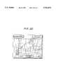
- FIG. 1is a view illustrating part of interior of a vehicle in which an on-vehicle data processing system and display device according to one embodiment of the present invention are mounted.
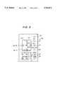
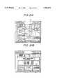
- FIG. 2is a block diagram illustrating the system of the embodiment.
- FIG. 3is a view illustrating a control unit.
- FIG. 4is a flow chart illustrating the basic operation of the system according to the embodiment of the present invention.
- FIG. 5is a flow chart illustrating the menu selection.
- FIG. 6is a flow chart illustrating the running mode image display.
- FIG. 7is a flow chart illustrating the stop mode image display.
- FIG. 8is a flow chart illustrating the speedometer display.
- FIG. 9is a flow chart illustrating the display of "mainte" item.
- FIGS. 10(A) and 10(B)illustrate examples of menu images.
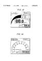
- FIG. 11is a view illustrating a speedometer image in a running mode.
- FIG. 12is a view illustrating a power meter image in a running mode.
- FIG. 13is a view illustrating a torque meter image in a running mode.
- FIG. 14is a view illustrating a tachometer image in a running mode.
- FIG. 15is a view illustrating a boost meter image in a running mode.
- FIG. 16is a view illustrating an eco meter image in a running mode.
- FIGS. 17(A) and 17(B)illustrate "mainte" display in a running and stop mode.
- FIG. 18is a view illustrating "trip" display in a stop mode.
- FIG. 19(A) and 19(B)illustrate "travel" display in a running and stop mode.
- FIG. 20is a view illustrating "record" display in a stop mode.
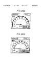
- FIG. 21(A) and 21(B)illustrate "trace" display in a running and stop mode.
- FIG. 22is a view illustrating "graph" display in a stop mode.
- FIG. 23is a flow chart illustrating the accumulation of the data history.
- FIG. 24is a flow chart illustrating the graphic display operation of the data history.
- FIG. 25(A) and 25(B)illustrate the input and display images of warning value.
- FIGS. 26(A) and 26(B)respectively show the images for daytime and night with brightness of the foreground and the backgrounds being correspondingly reversed.
- FIG. 1schematically shows the inside of a vehicle around the driver's seat in which an on-vehicle data processing system and display device according to this embodiment are mounted.
- An on-vehicle display device 10is fixedly mounted on a position that can be viewed by the driver while in his or her seat.
- the on-vehicle display device 10can be controlled relating to its display states through a remote control unit 20.
- the on-vehicle display device 10may be any one of commercially available television (TV) displays, navigation system displays and other displays made exclusively for the present invention. In this embodiment, a commercially available TV display device is used.
- TVtelevision
- navigation system displaysnavigation system displays
- other displaysmade exclusively for the present invention.
- a commercially available TV display deviceis used.
- FIG. 2shows a block diagram of a on-vehicle data processing system in this embodiment.
- the on-vehicle data processing systemcomprises a running data processing circuit 30 and a memory 40.
- the running data processing circuit 30receives control signals from the remote control unit 20 and also other signals from various parts of the vehicle.
- the vehiclehas an engine 50 electronically controlled by an engine control unit 52.
- the engine control unit 52provides, to the running data processing circuit 30, pulse signals representing engine speed, pulse signals representing the number of revolution of the tire, voltage signals representing a capacity of air intake of the engine, pulse signals representing injection quantity and other pulse signals.
- the running data processing circuit 30comprises a mode setting unit 32 and a display data processing unit 34.
- the mode setting unit 32determines the speed of the vehicle from the input signals and uses the determined speed to set one of running and stop modes.
- a first reference speed at which the running mode is switched to the stop modeis set to be lower than a second reference speed at which the stop mode is switched to the running mode.
- the display data processing unit 34is responsive to the input signals for computing various running data in the vehicle. In the running mode, the display data processing unit 34 displays the running states of the vehicle in real time on the display device 10.
- the memory 40stores the signals input to the running data processing circuit 30 and the running data computed by the running data processing circuit 30 in the running mode, if necessary.
- the display data processing unit 34reads data from the memory 40, computes details of the vehicle information and displays the details of the data on the display device 10.
- the mode setting unit 32provides a hysteresis characteristic to the reference speeds used to switch between the stop and running modes.
- the displayed imagescan be prevented from frequently being switched from one to another.
- stable imagesare provided on the on-vehicle display device.
- items to be displayed in the running modeinclude speed, power, tacho (engine speed), torque, boost and eco (fuel consumption), as shown in FIG. 10(A). Any of these items can be selected by the driver.
- FIGS. 11 to 16illustrate the displayed images in the running mode representing these items.
- selectable items to be displayed in the stop modeinclude “mainte”, “trip”, “travel”, “record”, “trace”, “graph”, “set up” and “pit off”, as shown in FIG. 10(B).
- FIGS. 17A and B, 18, 19A and B, 20, 21A and B, 22, and 25A and Bshow the displayed images in the stop mode representing the above items.
- the "pit off"is used to instruct the continuous display of the running mode images even in the stop mode.
- each of the running mode images shown in FIGS. 11 to 16indicates an item selected and displayed in the running mode while the top right corner represents an item selected in the stop mode.
- the top right corner of each of the stop mode images shown in FIGS. 17A and B, 18, 19A and B, 20, 21A and B, 22, and 25A and Bindicates an item selected and displayed in the stop mode while the top left corner represents a selected item in the running mode.
- the display data processing unit 34indicates larger characters in the running mode and smaller characters in the stop mode.
- the drivercan more easily view the running mode images indicating the vehicle running states in real time.
- the details of the vehicle informationcan be displayed with full consideration given to their contents.
- the display data processing unit 34also functions to display the foreground and background reversed in brightness for daytime or night. Both in the daytime and night, the images can be more clearly viewed by the driver.
- FIGS. 26A and Bshow an example of the image switched in brightness for daytime or night.
- the daytime image shown in FIG. 26(A)can be switched to the night image shown in FIG. 26(B) or vice versa. It is selected herein that the frequently changing parts such as letters, indicators and others are in foreground while the other parts are in background.
- the background and foregroundare white and black, respectively.
- the white and blackare reversed from the daytime image.
- the brightness of the foregroundcan be fixed while the brightness of the background can be regulated.
- FIG. 3shows the details of the remote control unit 20 used in this embodiment.
- the remote control unit 20comprises a power key 21, a change key 22 for switching TV display to the system of this embodiment or vice versa, a menu key 23, a start/stop key 24, a reset key 25, an item selection key 26 including function keys 26-1, 26-2 . . . 26-5 and other keys 27, 28 and 29.
- FIG. 4shows a flow chart representing the basic operation of the system according to this embodiment.
- a predetermined initializationis executed at step 100.
- the menu flagis set "1" when the menu image shown in FIG. 10 is called to select any item.
- step 104it is determined whether the vehicle is in running or stop mode. In the running mode, a running flag is set "1". In the stop mode, the running flag is set "0".
- a running mode image representing the item currently selectedis displayed on the display device 10 (step 106).
- a stop mode image representing the item currently selectedis displayed on the display device 10 (step 108).
- FIG. 5shows a flow chart illustrating the menu selection.
- the menu flagis set "0" at step 210.
- a menu image as shown in FIG. 10(A) or 10(B)is displayed.
- the item currently selectedis highlighted to be brighter than the other items (step 214).
- step 220When a desired item is highlighted and the OK key 26-5 in the remote control unit 20 is operated, the menu selection process is completed (step 220). Then, the running or stop mode image representing that newly selected item will be displayed.
- a corresponding drive (DR) mode flagis set at any of "0"-"5", respectively.
- a corresponding pit (PT) mode flagis set at any of "0"-"7", respectively.
- FIG. 6illustrates the flow chart of the running mode image display representing the item selected at step 106 in FIG. 4.
- the display item (drive mode flag) selected by the running mode menu selection (step 112)is identified at steps 310-320 for drive mode flags 0,1 . . . 5, respectively.
- the running mode image of this display itemis displayed at steps 330-340, respectively.
- a speed limitmay previously be set as a warning value, as will be described later. Each time when the speed of the vehicle reaches the warning value, the driver will be warned by blinks of the image or the like. This may prevent the vehicle from being driven on streets greater than the speed limit.
- the running data processing circuit 30can be responsive to input data for computing the vehicle power, engine speed, torque boost, fuel consumption and other factors substantially in real time, these computed factors being displayed on the display device 10 as shown in FIGS. 12-16 (steps 330-340).
- the drivercan obtain data which would not be obtained from the on-vehicle meters substantially in real time from the display device 10. For example, if the fuel consumption is degraded, the acceleration pedal can be pressed in a manner to save the fuel consumption.
- the system of this embodimentWhen the running mode images of the respective items are to be displayed as shown in FIG. 6, the system of this embodiment writes the data of the displayed items sequentially into the memory 40 as a data history. For example, if the speed is to be displayed in the running mode image, the data relating to the speed are sequentially written into the memory 40 as a data history. Thus, the data history can be displayed on the display device as will be described later.
- FIG. 8shows a flow chart illustrating the detailed operation (step 420) for a display of a speedometer in the running mode.
- the background image (part with no motion or with less motion) of FIG. 11is first displayed at step 510.
- the pointer of the speedometer and peak speed displaysare then initialized at steps 512 and 514.
- the speed datais read out at step 516 and the pointer of the speedometer corresponding to the foreground image (part with motion) is displayed in real time at step 518.
- the peak speedis displayed on the display device at step 520.
- the speed and its peakcan be displayed on the display device in real time, as shown in FIG. 11.
- Such a display of running mode imageis continued during the period that it is determined at step 524 that the vehicle is in the running mode.
- the speed of the vehicleis equal to or lower less than 10 Km/Hour and the PT mode flag is any value other than 7, it is determined that the vehicle is in the stop mode. Otherwise, it is determined that the vehicle is in the running mode.
- step 524If it is determined at step 524 that the vehicle is switched from the running mode to the stop mode, the program proceeds to step 526 and sets the running flag to "0" and the display of the running mode image is terminated.
- step 522If the menu button 23 of the remote control unit 20 is operated when the running mode image is displayed (step 522), the program proceeds to step 528 at which the menu flag is set "1" and such a display of the menu image as shown in FIG. 10(A) will be made.
- running mode images of the other itemsare displayed substantially in the same manner, only the running mode image of "eco" (fuel consumption) item is different from the other running mode images in that the peak value displayed at step 520 is replaced by an average value.
- FIG. 7shows a flow chart of the display of such a stop mode image display representing the item selected at step 108 in FIG. 4.
- this stop mode imageWhen this stop mode image is to be displayed, it is first determined from the value of the PT mode flag at steps 410, 412 . . . 424 which item is selected from the menu image shown in FIG. 10(B) for pit mode flags 0,1 . . . 7, respectively.
- the stop mode image of the selected itemis displayed on the display device, respectively.
- a stop mode image as shown in FIG. 17(A)is displayed (step 430).
- the "mainte" display imageis used as a record of the history of maintenance. For example, four factors including engine oil, engine oil filter, tire and free items, a set distance to be traveled can be displayed and a covered distance is indicated by bar graph. Thus, the conditions of the vehicle in the maintenance item can promptly be recognized by the driver.
- step 432If the "trip" item is selected from the menu image, such a stop mode image as shown in FIG. 18 is displayed (step 432). In this display, time passed from when the reset button 25 of the remote control unit 20 is pressed, covered distance, amount of consumed fuel and average fuel consumption are computed and displayed.
- step 434If the "travel" item is selected from the menu image, such a stop mode image as shown in FIG. 19(A) is displayed (step 434). This indicates the remaining part in the distance set by the driver, time required to travel the remaining distance, expected amount of fuel consumption and expected average fuel consumption. The remaining distance is also displayed in the level meter.
- Change of the set distanceis performed by opening a window as shown in FIG. 19(B), in the same manner as when the aforementioned menu image is changed.
- step 436a stop mode image as shown in FIG. 20 is displayed (step 436).
- This imageshows, for example, three different past records of distance, time, speed and fuel consumption from the "start” to the “stop” through operation of the button 24 of the remote control unit 20 in the running mode. The past data are sequentially erased and replaced by a new data.
- Such a displayis effective when a distance from the driver's home to his or her office, time required to travel the distance, speed and fuel consumption are measured through different routes. As a result, the shortest distance from the driver's home to his or her office or the course requiring less time can be objectively determined.
- a stop mode image as shown in FIG. 21(A)is displayed (step 438). This image indicates measurements of running time, engine speed, speed and power relating to a transverse axis on which preset distances are placed.
- the set button 28is pressed at a step in which the image shown in FIG. 21(A) is displayed.
- Such an input window as shown in FIG. 21(B)is then opened to input measured distances in the same manner as described earlier.
- the vehicleis driven and the start button 24 of the remote control unit 20 is turned on.
- the engine speed, speed, power and required timeare sequentially stored in the memory 40.
- the dataare read out from the memory 40 and displayed on the display device as such an image as shown in FIG. 21(A).
- the driveroperates the buttons 26-3 and 26-4 in the remote control unit 20 to move a cursor K in the horizontal direction. Numerical values of the respective data at the position of the cursor K are indicated on the corresponding display position.
- the drivercan view such displayed data to analyze the running course.
- a stop mode image as shown in FIG. 22is displayed (step 440).
- the data history of the data displayed in the running modee.g., data history of speed
- the data history of the data displayed in the running modeare read out from the memory 40 and graphically displayed on the display device as shown in FIG. 22.
- the past variations of the speed for several minutesare graphically displayed on the display device. Since the variations of the data displayed in real time in the running mode are graphically indicated as a data history, the driver can promptly determine the past history of the data from the displayed image.
- the system of this embodimentincludes means for setting a warning value relating to at least one item of one of the running and stop mode images and for outputting a warning signal as the value of the selected item for which the warning value is set reaches the warning value.
- warning valuescan be set for items of "speed", “power” and "tacho”.
- the set button 28is operated to display a menu image as shown in FIG. 25(A) on the display device.
- buttons 26-1 and 26-2are then used to select an item for setting a warning value from the "speed”, "power” and “tacho” items.
- the item of "speed”is selected.
- buttons 26-3 and 26-4are then used to input numerical values for warning a speed. Thereafter, the OK button 26-5 is pressed to terminate the setting of alarm.
- the running data processing circuit 30intermittently displays an alarm image on the display device as shown in FIG. 25(B), with a warning sound when the alarm setting item (e.g., "speed" item) reaches the warning value.
- the alarm setting iteme.g., "speed" item
- the drivercan promptly know that the speed reaches the warning level, from the alarm display and warning sound. This can prevent the vehicle from being driven greater than the speed limit.
- the warning displays of "tacho”, "power” and so oncan be set to prevent the overrunning of the engine, the overoutput of the power and so on.
- the details of the vehicle informationcan be displayed on the display device as stop mode images such that the driver can know the detailed factors of the vehicle information from the stop mode images.
- the stop mode imagesindicate smaller characters included therein than those of the running mode images so that the more detailed vehicle information can be transmitted to the driver.
- FIG. 9shows a flow chart illustrating the details of display operation for the "mainte" item (step 420) of FIG. 7.
- a background display flagis set "1" at step 610.
- the programthen proceeds through step 612 to step 614.
- the background display flagis again set "0".
- the backgroundis displayed at step 616. If no key is operated at this time, the program proceeds through steps 618, 620 and 622 to step 624.
- step 624it is determined whether the speed of the vehicle is equal to or higher than 15 Km/Hour. If the speed of the vehicle does not exceed 15 Km/Hour, it is determined that the stop mode continues. The program returns to step 612 wherein a "mainte" display image as shown in FIG. 17(A) continues to be displayed.
- step 624As the speed of the vehicle exceeds 15 Km/Hour, it is determined at step 624 that the vehicle has been switched from the stop mode to the running mode. At step 626, the running flag is set "1" and the running mode image of the item selected at present begins to be displayed.
- the stop modeis switched to the running mode at 15 Km/Hour.
- the running modeis switched to the stop mode at 10 Km/Hour.
- a reference speed at which the vehicle is switched from the stop mode to the running modeis higher than another reference speed at which the vehicle is switched from the running mode to the stop mode.
- step 618distance data for maintenance begin to be input at step 630.
- four items of engine oil, filter, tire and freedomare independently set with respect to their distances.
- the OK button 26-5is then operated to open such a window as shown in FIG. 17(B).
- the buttons 26-1 to 26-4 in the remote control unit 20are then operated to input and set a desired distance.
- the OK button 26-5is operated to complete the input operation and to close the window, the display being returned back to the image of FIG. 17(A).
- step 630When the series of distance data inputs (step 630) is terminated, the background flag is set "1" at step 632. The program then proceeds from step 620 to step 612 wherein the "mainte" image is displayed in the same manner as described above.
- the menu button 23 of the remote control unit 20is operated.
- the programproceeds through steps 618 and 628 to step 634.
- the menu flagis set "1".
- the programthen proceeds to the selection of menu images shown in FIG. 5 through steps 620 and 622. Thus, a desired item can be selected.
- FIG. 23shows a flow chart illustrating the writing of a data history into the memory 40 for a graph display shown in FIG. 22 in the running mode.
- FIG. 24shows a flow chart illustrating the details of display operation for the graph on the display device using the written data history.
- an interruption program to the main programis periodically executed every 0.3 seconds at step 710 of FIG. 23.
- the speed data being displayed in the running mode imageis read into the memory 40 at an address specified by INTI.
- the address INTIis then increased by one (step 714).
- step 716the program proceeds from step 716 to step 718 wherein the INTI value is set "0".
- the speed data readare sequentially stored in the memory.
- the last 256 speed data readwill always be written in the memory 40 at addresses 0-255.
- FIG. 24shows a display operation of a graph using the history data written into the memory 40 on the display device.
- a background image as shown in FIG. 22is displayed.
- a value of a read address GRFCis set at an address (INTI-1) which has been specified to be the last address written into the memory 40.
- a graphic counter GRFIis set "0".
- the data of address GRFCis then read out from the memory 40 and graphically displayed on the display device.
- the read address GRFCis decreased by one.
- the graphic counter GRFIis increased by one.
- Such a counting operationis repeatedly executed until the count of the graphic counter GRFI, for example, reaches 200 (step 822), and the data history such as speed and so on are graphically displayed on the display device, as shown in FIG. 22.
- the menu flag setting at steps 824-828 as well as the stop mode determination at step 830are similar to those of FIG. 9 and will not further be described herein.
- the difference between the graph of data history shown in FIG. 22 and the graph shown in FIG. 21Aresides in that the horizontal axis in the graph of FIG. 22 is set with reference to time while the horizontal axis in the graph of FIG. 21A is set with reference to distance.
- the graph shown in FIG. 22can be made to display the data history for one minute or several minutes in the past.
- the drivercan visually and promptly grasp the variations of speed from one minute to several minutes in the past. Based on such data, the driver can try to improve his or her own driving technique.
- the on-vehicle data processing system of the present inventioncan indicate on the display device the running mode images with large characters more easily viewed by the driver while in the running mode and the stop mode images with smaller characters to display the details of the vehicle information while in the stop mode.
- the drivercan obtain various information from the on-vehicle display device and effectively use the on-vehicle display device.
Landscapes
- Engineering & Computer Science (AREA)
- Chemical & Material Sciences (AREA)
- Combustion & Propulsion (AREA)
- Transportation (AREA)
- Mechanical Engineering (AREA)
- Physics & Mathematics (AREA)
- General Physics & Mathematics (AREA)
- Instrument Panels (AREA)
- Navigation (AREA)
- Traffic Control Systems (AREA)
Abstract
Description
Claims (16)
Applications Claiming Priority (3)
| Application Number | Priority Date | Filing Date | Title |
|---|---|---|---|
| JP5-273194 | 1993-10-04 | ||
| JP27319493AJP3533685B2 (en) | 1993-10-04 | 1993-10-04 | Vehicle image data calculation device and control method therefor |
| PCT/JP1994/001659WO1995010026A1 (en) | 1993-10-04 | 1994-10-04 | Image data operating device for vehicle |
Publications (1)
| Publication Number | Publication Date |
|---|---|
| US5781872Atrue US5781872A (en) | 1998-07-14 |
Family
ID=17524418
Family Applications (1)
| Application Number | Title | Priority Date | Filing Date |
|---|---|---|---|
| US08/448,447Expired - LifetimeUS5781872A (en) | 1993-10-04 | 1994-10-04 | On-vehicle data processing and display system responsive to a vehicle mode of operation |
Country Status (4)
| Country | Link |
|---|---|
| US (1) | US5781872A (en) |
| EP (1) | EP0672892A4 (en) |
| JP (1) | JP3533685B2 (en) |
| WO (1) | WO1995010026A1 (en) |
Cited By (50)
| Publication number | Priority date | Publication date | Assignee | Title |
|---|---|---|---|---|
| US6201540B1 (en)* | 1998-01-07 | 2001-03-13 | Microsoft Corporation | Graphical interface components for in-dash automotive accessories |
| US6256558B1 (en)* | 1998-01-19 | 2001-07-03 | Denso Corporation | Vehicle display system with drive enforcement control |
| US6266589B1 (en)* | 1999-11-19 | 2001-07-24 | International Business Machines Corporation | Speed-based disabling of functionality for automotive applications |
| US20020077779A1 (en)* | 2000-10-17 | 2002-06-20 | Spx Corporation | Apparatus and method for displaying diagnostic values |
| US6449535B1 (en) | 1997-01-28 | 2002-09-10 | American Calcar, Inc. | Method and system for adjusting a function in a vehicle |
| US20030046693A1 (en)* | 2001-08-29 | 2003-03-06 | Digeo, Inc. | System and method for focused navigation within an interactive television user interface |
| US20030046695A1 (en)* | 2001-08-29 | 2003-03-06 | Digeo, Inc. | System and method for enabling focused navigation using filtering and direct-tune buttons |
| US6580984B2 (en) | 2001-09-07 | 2003-06-17 | Visteon Global Technologies, Inc. | Method and device for supplying information to a driver of a vehicle |
| US6594557B1 (en)* | 1999-09-27 | 2003-07-15 | Visteon Global Technologies, Inc. | Utilizing intelligent software agents in a mobile vehicle |
| US6674497B2 (en)* | 1998-10-02 | 2004-01-06 | Mannesmann Vdo Ag | Electrooptic display device |
| US6721634B1 (en)* | 1999-10-19 | 2004-04-13 | Robert Bosch Gmbh | Method and device for displaying a measured value in a vehicle |
| US6748319B2 (en)* | 2000-08-09 | 2004-06-08 | Honda Giken Kogyo Kabushiki Kaisha | Remaining distance meter |
| US20060043255A1 (en)* | 2004-09-01 | 2006-03-02 | Benq Corporation | Electronic device with height adjusting mechanism |
| US20060052908A1 (en)* | 2004-09-06 | 2006-03-09 | Denso Corporation | Vehicle stability control system |
| US20060061464A1 (en)* | 2004-09-06 | 2006-03-23 | Denso Corporation | Body action information system |
| US20060218591A1 (en)* | 2001-08-29 | 2006-09-28 | Digeo, Inc. | System and method for focused navigation using option type filters |
| US20060236362A1 (en)* | 2001-08-29 | 2006-10-19 | Digeo, Inc. | System and method for focused navigation within a user interface |
| US20060287792A1 (en)* | 2005-04-20 | 2006-12-21 | Tim Jarrett | Agricultural vehicle performance maps |
| US20070011623A1 (en)* | 2001-08-29 | 2007-01-11 | Digeo, Inc. | System and method for focused navigation within a user interface |
| US20070067415A1 (en)* | 2005-09-22 | 2007-03-22 | Shuichi Kawaguchi | In-vehicle display apparatus and in-vehicle proxy server for use therewith |
| US20070093956A1 (en)* | 2005-10-26 | 2007-04-26 | Samsung Electronics Co., Ltd. | Method for processing multimedia broadcasting data in wireless terminal while driving vehicle |
| US20070176797A1 (en)* | 2006-01-30 | 2007-08-02 | Rhodes Louis A | Removable electronic tablet for vehicle instrument panel |
| US20090030582A1 (en)* | 2007-07-28 | 2009-01-29 | Dr. Ing. H.C.F. Porsche Aktiengesellschaft | Motor Vehicle, Indicating Device and Operating Method |
| US7501939B1 (en) | 2005-08-10 | 2009-03-10 | Yazaki North America, Inc. | Display device with dimmable segments |
| US7594246B1 (en)* | 2001-08-29 | 2009-09-22 | Vulcan Ventures, Inc. | System and method for focused navigation within a user interface |
| US20090251303A1 (en)* | 2008-04-04 | 2009-10-08 | Fuji Jukogyo Kabushiki Kaisha | Vehicle display device |
| US7650569B1 (en) | 2001-08-29 | 2010-01-19 | Allen Paul G | System and method for focused navigation within a user interface |
| FR2935829A1 (en)* | 2008-09-05 | 2010-03-12 | Peugeot Citroen Automobiles Sa | Information e.g. carbon dioxide emission level, displaying system for motor vehicle, has LCD whose portion includes graph bar with segments, where ignition of segments is controlled by control unit based on emission level of carbon dioxide |
| US7735102B1 (en) | 2001-08-29 | 2010-06-08 | Billmaier James A | System and method for focused navigation within a user interface |
| US20100191404A1 (en)* | 2009-01-29 | 2010-07-29 | Kubota Corporation | Display System for Work Vehicle |
| US20110144857A1 (en)* | 2009-12-14 | 2011-06-16 | Theodore Charles Wingrove | Anticipatory and adaptive automobile hmi |
| US20110148614A1 (en)* | 2009-10-14 | 2011-06-23 | Gm Global Technology Operations, Inc. | Display and method for calculating an "eco" meter index to be displayed for the driver of a motor vehicle |
| US8099680B1 (en) | 2002-03-12 | 2012-01-17 | Arris Group, Inc. | System and method of contextual pre-tuning |
| WO2012047166A1 (en)* | 2010-10-07 | 2012-04-12 | Scania Cv Ab | Method and system for determining operating states of a motor vehicle |
| US20120262403A1 (en)* | 2009-12-22 | 2012-10-18 | Dav | Control device for a motor vehicle |
| FR2978280A1 (en)* | 2011-07-22 | 2013-01-25 | Thales Sa | AIRBORNE BEHAVIOR MONITORING SYSTEM FOR PREDICTING ANOMALIES |
| US8473868B1 (en) | 2006-10-27 | 2013-06-25 | Arris Group, Inc. | System and method for reverse hierarchical navigation within a user interface |
| US8600830B2 (en) | 2003-02-05 | 2013-12-03 | Steven M. Hoffberg | System and method for providing a payment to a non-winning auction participant |
| US20140257675A1 (en)* | 2013-03-07 | 2014-09-11 | Honda Motor Co., Ltd. | System and method for indicating engine power band information on a tachometer display |
| US9026317B2 (en)* | 2011-09-29 | 2015-05-05 | Komatsu Ltd. | Display unit of work machine and work machine mounted with the display unit |
| US20150243168A1 (en)* | 2012-10-31 | 2015-08-27 | Bayerische Motoren Werke Aktiengesellschaft | Vehicle Assistance Device |
| US9242653B2 (en) | 2010-09-28 | 2016-01-26 | Bayerische Motoren Werke Aktiengesellschaft | Driver assistance system for assisting the driver for the purpose of consumption-controlled driving |
| CN105403415A (en)* | 2015-12-29 | 2016-03-16 | 腾讯科技(深圳)有限公司 | Data processing method of vehicle diagnosis system, device and system |
| US9493071B2 (en)* | 2010-09-28 | 2016-11-15 | Bayerische Motoren Werke Aktiengesellschaft | Driver assistance system for driver assistance for consumption controlled driving |
| US9744904B1 (en)* | 2016-02-09 | 2017-08-29 | Corinne Tolliver | Vehicle alarm |
| US9794797B2 (en) | 2005-10-04 | 2017-10-17 | Steven M. Hoffberg | Multifactorial optimization system and method |
| CN107336670A (en)* | 2017-05-27 | 2017-11-10 | 杰克陈 | Chinese herbaceous peony light source position identification device and vehicular high beam lamp automatic control system |
| US10275137B2 (en)* | 2012-11-05 | 2019-04-30 | Trane International | Method of displaying incrementing or decrementing number to simulate fast acceleration |
| US20190152318A1 (en)* | 2015-01-02 | 2019-05-23 | Volkswagen Ag | User interface and method for operating a user interface for a transportation means |
| US10513184B2 (en)* | 2017-06-26 | 2019-12-24 | Lg Electronics Inc. | Interface system for vehicle |
Families Citing this family (39)
| Publication number | Priority date | Publication date | Assignee | Title |
|---|---|---|---|---|
| JPH095120A (en)* | 1995-06-15 | 1997-01-10 | Moriyama Kogyo Kk | Meter-display changeover device |
| DE69625142T2 (en)* | 1995-09-08 | 2003-04-24 | Aisin Aw Co., Ltd. | Car navigation system |
| JPH09123848A (en)* | 1995-11-06 | 1997-05-13 | Toyota Motor Corp | Information display device for vehicles |
| JP3778384B2 (en)* | 1996-09-20 | 2006-05-24 | 富士通テン株式会社 | Electronic device function selection and adjustment device |
| US5757268A (en)* | 1996-09-26 | 1998-05-26 | United Technologies Automotive, Inc. | Prioritization of vehicle display features |
| IT1289710B1 (en)* | 1996-12-04 | 1998-10-16 | Fiat Ricerche | VEHICLE INFORMATION DISPLAY DEVICE |
| DE19708263C2 (en)* | 1997-02-28 | 1999-09-30 | Grundig Ag | Display device for a vehicle |
| JP3796884B2 (en)* | 1997-03-31 | 2006-07-12 | マツダ株式会社 | Operation device for automotive control device |
| US5949345A (en)* | 1997-05-27 | 1999-09-07 | Microsoft Corporation | Displaying computer information to a driver of a vehicle |
| DE19757564A1 (en)* | 1997-12-23 | 1999-07-01 | Mannesmann Vdo Ag | Display device |
| DE19816795A1 (en)* | 1998-04-16 | 1999-10-21 | Bosch Gmbh Robert | Representations of objects in a bitmap format |
| US6667726B1 (en) | 1999-01-19 | 2003-12-23 | C.R.F. Societa Consortile Per Azioni | Vehicle display device |
| RU2162204C1 (en)* | 2000-03-06 | 2001-01-20 | Закрытое акционерное общество Объединенное конструкторское бюро "Русская авионика" | Multifunctional aboard indicator |
| JP4156814B2 (en)* | 2001-01-10 | 2008-09-24 | 本田技研工業株式会社 | Vehicle meter device |
| US6574531B2 (en)* | 2001-07-25 | 2003-06-03 | Visteon Global Technologies, Inc. | Method and apparatus for providing information to an occupant of a vehicle |
| RU2206872C2 (en)* | 2001-08-31 | 2003-06-20 | Закрытое акционерное общество Объединенное конструкторское бюро "Русская авионика" | Indication system of aircraft |
| US7079018B2 (en) | 2002-04-18 | 2006-07-18 | Michelin Recherche Et Technique S.A. | System state indicator |
| FR2838821A1 (en)* | 2002-04-18 | 2003-10-24 | Michelin Soc Tech | Dashboard indicator for indicating the state of the various physical characteristics of the systems in the automotive vehicle |
| JP4535277B2 (en)* | 2005-06-01 | 2010-09-01 | 日立建機株式会社 | Construction machine display device |
| US7317385B2 (en)* | 2005-08-02 | 2008-01-08 | Johnson Controls Technology Company | In-vehicle animation bypass system and method |
| JP4498302B2 (en)* | 2006-04-05 | 2010-07-07 | 日立建機株式会社 | Display device for wheel type work machine |
| DE102006058214A1 (en)* | 2006-12-11 | 2008-06-19 | Bayerische Motoren Werke Ag | motor vehicle |
| JP4812613B2 (en)* | 2006-12-27 | 2011-11-09 | 日立建機株式会社 | Wheeled work machine |
| JP4958543B2 (en)* | 2006-12-28 | 2012-06-20 | 日立建機株式会社 | Display device for wheel type work machine |
| US7683771B1 (en) | 2007-03-26 | 2010-03-23 | Barry Loeb | Configurable control panel and/or dashboard display |
| DE102007042294A1 (en)* | 2007-09-06 | 2009-03-12 | Volkswagen Ag | Display unit for a motor vehicle and method for controlling a display unit |
| US20100049397A1 (en)* | 2008-08-22 | 2010-02-25 | Garmin Ltd. | Fuel efficient routing |
| DE102009007436B4 (en)* | 2009-02-04 | 2021-06-24 | Volkswagen Ag | Method and device for displaying at least one course of values for a vehicle and a vehicle |
| DE102009050056A1 (en) | 2009-10-21 | 2011-05-05 | Volkswagen Ag | Method for displaying information in vehicle, involves detecting parameter between standard mode and travel mode, where speed progression is detected in time interval, where speed progression is provided as another parameter |
| DE102010020894A1 (en)* | 2010-05-18 | 2011-11-24 | Volkswagen Ag | Method and device for displaying information in a vehicle |
| JP5787161B2 (en)* | 2011-11-09 | 2015-09-30 | 日本精機株式会社 | Vehicle instrument |
| JP6118957B2 (en)* | 2012-12-29 | 2017-04-26 | 株式会社ユピテル | Vehicle system and program |
| CN103342113A (en)* | 2013-07-31 | 2013-10-09 | 大陆汽车投资(上海)有限公司 | Vehicle alarming method |
| WO2015133070A1 (en)* | 2014-03-04 | 2015-09-11 | 株式会社デンソー | Vehicle display device |
| JP6318706B2 (en)* | 2014-03-04 | 2018-05-09 | 株式会社デンソー | Vehicle display device |
| JP2016114365A (en)* | 2014-12-11 | 2016-06-23 | 日本精機株式会社 | Gauge for vehicle |
| JP6240862B2 (en)* | 2016-04-27 | 2017-12-06 | 株式会社ユピテル | Control system and program |
| JP6531264B2 (en)* | 2017-01-24 | 2019-06-19 | 株式会社ユピテル | Vehicle system and program |
| DE102023123205A1 (en) | 2023-08-21 | 2025-02-27 | Audi Aktiengesellschaft | Method, operating device and computer program for adapting a graphical user interface of the operating device in a motor vehicle to a driving state of the motor vehicle |
Citations (22)
| Publication number | Priority date | Publication date | Assignee | Title |
|---|---|---|---|---|
| FR601130A (en)* | 1924-11-03 | 1926-02-23 | Chem Fab Auf Actien | Manufacturing process of a silica gel |
| US4196413A (en)* | 1977-11-29 | 1980-04-01 | Nippon Soken, Inc. | Dot-matrix type vehicle condition display apparatus |
| JPS5852565A (en)* | 1981-09-24 | 1983-03-28 | Yamaha Motor Co Ltd | Electric tachometer for vehicle |
| US4398258A (en)* | 1979-12-26 | 1983-08-09 | Nippondenso Co., Ltd. | Malfunction procedure indicating system and method |
| JPS5945233A (en)* | 1982-09-07 | 1984-03-14 | Toshiba Corp | Automotive display device |
| EP0122043A1 (en)* | 1983-04-05 | 1984-10-17 | Gaydon Technology Limited | Driver's information display for motor vehicles |
| JPS59229699A (en)* | 1983-06-09 | 1984-12-24 | 松下電器産業株式会社 | Vehicle-mounted driving information display device |
| US4521885A (en)* | 1983-01-05 | 1985-06-04 | Towmotor Corporation | Diagnostic display apparatus |
| JPS60158315A (en)* | 1984-01-30 | 1985-08-19 | Yokogawa Hokushin Electric Corp | Trend-graph display device |
| JPS60179608A (en)* | 1984-02-28 | 1985-09-13 | Shimadzu Corp | Process data display device |
| US4551801A (en)* | 1983-02-07 | 1985-11-05 | Dickey-John Corporation | Modular vehicular monitoring system |
| JPS613045A (en)* | 1984-06-18 | 1986-01-09 | Hitachi Ltd | Electrophoretic apparatus |
| JPS61150874A (en)* | 1984-12-21 | 1986-07-09 | Daihatsu Motor Co Ltd | Steering angle indicator of vehicle |
| JPS6259812A (en)* | 1985-09-09 | 1987-03-16 | Mazda Motor Corp | Multiple display device for vehicle |
| JPS62282225A (en)* | 1986-05-30 | 1987-12-08 | Nippon Denso Co Ltd | Meter device for vehicle |
| US4906970A (en)* | 1986-07-23 | 1990-03-06 | Nissan Motor Co., Ltd. | Vehicle on-board diagnosing system |
| US4924418A (en)* | 1988-02-10 | 1990-05-08 | Dickey-John Corporation | Universal monitor |
| EP0414402A1 (en)* | 1989-08-24 | 1991-02-27 | Delco Electronics Corporation | Silhouette illuminated instrument panel display apparatus |
| JPH04273016A (en)* | 1991-02-28 | 1992-09-29 | Omron Corp | Information diskplay device for car |
| US5267159A (en)* | 1990-09-13 | 1993-11-30 | Neall Donald L O | Mileage recording and display apparatus |
| US5309139A (en)* | 1990-08-03 | 1994-05-03 | Austin Charles W | Vehicle monitoring system |
| US5450321A (en)* | 1991-08-12 | 1995-09-12 | Crane; Harold E. | Interactive dynamic realtime management system for powered vehicles |
Family Cites Families (2)
| Publication number | Priority date | Publication date | Assignee | Title |
|---|---|---|---|---|
| JPS613045U (en)* | 1985-05-30 | 1986-01-09 | ジエコー株式会社 | Automotive electronic warning device |
| DE3622632C2 (en)* | 1986-07-05 | 1995-11-30 | Fichtel & Sachs Ag | Electronic device for measuring and displaying the speed and other data on a bicycle |
- 1993
- 1993-10-04JPJP27319493Apatent/JP3533685B2/ennot_activeExpired - Fee Related
- 1994
- 1994-10-04USUS08/448,447patent/US5781872A/ennot_activeExpired - Lifetime
- 1994-10-04EPEP94927841Apatent/EP0672892A4/ennot_activeWithdrawn
- 1994-10-04WOPCT/JP1994/001659patent/WO1995010026A1/ennot_activeApplication Discontinuation
Patent Citations (22)
| Publication number | Priority date | Publication date | Assignee | Title |
|---|---|---|---|---|
| FR601130A (en)* | 1924-11-03 | 1926-02-23 | Chem Fab Auf Actien | Manufacturing process of a silica gel |
| US4196413A (en)* | 1977-11-29 | 1980-04-01 | Nippon Soken, Inc. | Dot-matrix type vehicle condition display apparatus |
| US4398258A (en)* | 1979-12-26 | 1983-08-09 | Nippondenso Co., Ltd. | Malfunction procedure indicating system and method |
| JPS5852565A (en)* | 1981-09-24 | 1983-03-28 | Yamaha Motor Co Ltd | Electric tachometer for vehicle |
| JPS5945233A (en)* | 1982-09-07 | 1984-03-14 | Toshiba Corp | Automotive display device |
| US4521885A (en)* | 1983-01-05 | 1985-06-04 | Towmotor Corporation | Diagnostic display apparatus |
| US4551801A (en)* | 1983-02-07 | 1985-11-05 | Dickey-John Corporation | Modular vehicular monitoring system |
| EP0122043A1 (en)* | 1983-04-05 | 1984-10-17 | Gaydon Technology Limited | Driver's information display for motor vehicles |
| JPS59229699A (en)* | 1983-06-09 | 1984-12-24 | 松下電器産業株式会社 | Vehicle-mounted driving information display device |
| JPS60158315A (en)* | 1984-01-30 | 1985-08-19 | Yokogawa Hokushin Electric Corp | Trend-graph display device |
| JPS60179608A (en)* | 1984-02-28 | 1985-09-13 | Shimadzu Corp | Process data display device |
| JPS613045A (en)* | 1984-06-18 | 1986-01-09 | Hitachi Ltd | Electrophoretic apparatus |
| JPS61150874A (en)* | 1984-12-21 | 1986-07-09 | Daihatsu Motor Co Ltd | Steering angle indicator of vehicle |
| JPS6259812A (en)* | 1985-09-09 | 1987-03-16 | Mazda Motor Corp | Multiple display device for vehicle |
| JPS62282225A (en)* | 1986-05-30 | 1987-12-08 | Nippon Denso Co Ltd | Meter device for vehicle |
| US4906970A (en)* | 1986-07-23 | 1990-03-06 | Nissan Motor Co., Ltd. | Vehicle on-board diagnosing system |
| US4924418A (en)* | 1988-02-10 | 1990-05-08 | Dickey-John Corporation | Universal monitor |
| EP0414402A1 (en)* | 1989-08-24 | 1991-02-27 | Delco Electronics Corporation | Silhouette illuminated instrument panel display apparatus |
| US5309139A (en)* | 1990-08-03 | 1994-05-03 | Austin Charles W | Vehicle monitoring system |
| US5267159A (en)* | 1990-09-13 | 1993-11-30 | Neall Donald L O | Mileage recording and display apparatus |
| JPH04273016A (en)* | 1991-02-28 | 1992-09-29 | Omron Corp | Information diskplay device for car |
| US5450321A (en)* | 1991-08-12 | 1995-09-12 | Crane; Harold E. | Interactive dynamic realtime management system for powered vehicles |
Non-Patent Citations (6)
| Title |
|---|
| P. Andreas et al., "The Driver Information Systems of the Volkswagen Research Car Auto 2000," IEEE Transactions on Industrial Electronics, vol. ie-30, No. 2, May 1983, New York, pp. 132-137; p. 136, Right col., paragraph 6; Figs. 9-11. |
| P. Andreas et al., The Driver Information Systems of the Volkswagen Research Car Auto 2000, IEEE Transactions on Industrial Electronics, vol. ie 30, No. 2, May 1983, New York, pp. 132 137; p. 136, Right col., paragraph 6; Figs. 9 11.* |
| Patent Abstracts of Japan, vol. 009, No. 334 (P 417), Dec. 1985 & JP A 60 158315, Aug. 1985.* |
| Patent Abstracts of Japan, vol. 009, No. 334 (P-417), Dec. 1985 & JP-A-60 158315, Aug. 1985. |
| Patent Abstracts of Japan, vol. 010, No. 030 (P 426), Feb. 1986 & JP A 60 179608, Sep. 1985.* |
| Patent Abstracts of Japan, vol. 010, No. 030 (P-426), Feb. 1986 & JP-A-60 179608, Sep. 1985. |
Cited By (97)
| Publication number | Priority date | Publication date | Assignee | Title |
|---|---|---|---|---|
| US7062362B2 (en) | 1997-01-28 | 2006-06-13 | American Calcar Inc. | Technique for preconditioning climate control in a vehicle |
| US6587759B2 (en) | 1997-01-28 | 2003-07-01 | American Calcar Inc. | Technique for effectively providing information responsive to a notable condition in a vehicle |
| US6922616B2 (en) | 1997-01-28 | 2005-07-26 | American Calcar Inc. | Technique for effectively maintaining components of a vehicle |
| US6587758B2 (en) | 1997-01-28 | 2003-07-01 | American Calcar Inc. | Technique for adopting an adjustment of a vehicle function |
| US6449535B1 (en) | 1997-01-28 | 2002-09-10 | American Calcar, Inc. | Method and system for adjusting a function in a vehicle |
| US6459961B1 (en)* | 1997-01-28 | 2002-10-01 | American Calcar, Inc. | Technique for providing information upon a notable condition in a vehicle |
| US9387760B2 (en) | 1997-01-28 | 2016-07-12 | Talking Quick Tips, Inc. | Multimedia information and control system for automobiles |
| US6859687B2 (en) | 1997-01-28 | 2005-02-22 | American Calcar Inc. | Technique for temporal climate control in a vehicle |
| US20040162645A1 (en)* | 1997-01-28 | 2004-08-19 | American Calcar Inc. | Multimedia information and control system for automobiles |
| US20050203674A1 (en)* | 1997-01-28 | 2005-09-15 | Obradovich Michael L. | Multimedia information and control system for automobiles |
| US6201540B1 (en)* | 1998-01-07 | 2001-03-13 | Microsoft Corporation | Graphical interface components for in-dash automotive accessories |
| US6256558B1 (en)* | 1998-01-19 | 2001-07-03 | Denso Corporation | Vehicle display system with drive enforcement control |
| US6674497B2 (en)* | 1998-10-02 | 2004-01-06 | Mannesmann Vdo Ag | Electrooptic display device |
| US6594557B1 (en)* | 1999-09-27 | 2003-07-15 | Visteon Global Technologies, Inc. | Utilizing intelligent software agents in a mobile vehicle |
| US6721634B1 (en)* | 1999-10-19 | 2004-04-13 | Robert Bosch Gmbh | Method and device for displaying a measured value in a vehicle |
| US6266589B1 (en)* | 1999-11-19 | 2001-07-24 | International Business Machines Corporation | Speed-based disabling of functionality for automotive applications |
| US6748319B2 (en)* | 2000-08-09 | 2004-06-08 | Honda Giken Kogyo Kabushiki Kaisha | Remaining distance meter |
| US20020077779A1 (en)* | 2000-10-17 | 2002-06-20 | Spx Corporation | Apparatus and method for displaying diagnostic values |
| US7089096B2 (en)* | 2000-10-17 | 2006-08-08 | Spx Corporation | Apparatus and method for displaying diagnostic values |
| US7735102B1 (en) | 2001-08-29 | 2010-06-08 | Billmaier James A | System and method for focused navigation within a user interface |
| US20060236362A1 (en)* | 2001-08-29 | 2006-10-19 | Digeo, Inc. | System and method for focused navigation within a user interface |
| US8924854B2 (en) | 2001-08-29 | 2014-12-30 | Arris Enterprises, Inc. | System and method for focused navigation within a user interface |
| US20030046695A1 (en)* | 2001-08-29 | 2003-03-06 | Digeo, Inc. | System and method for enabling focused navigation using filtering and direct-tune buttons |
| US20100122290A1 (en)* | 2001-08-29 | 2010-05-13 | Allen Paul G | System and method for focused navigation within a user interface |
| US7487459B2 (en) | 2001-08-29 | 2009-02-03 | Digeo, Inc. | System and method for focused navigation using option type filters |
| US20060218591A1 (en)* | 2001-08-29 | 2006-09-28 | Digeo, Inc. | System and method for focused navigation using option type filters |
| US20030046693A1 (en)* | 2001-08-29 | 2003-03-06 | Digeo, Inc. | System and method for focused navigation within an interactive television user interface |
| US7650569B1 (en) | 2001-08-29 | 2010-01-19 | Allen Paul G | System and method for focused navigation within a user interface |
| US20070011623A1 (en)* | 2001-08-29 | 2007-01-11 | Digeo, Inc. | System and method for focused navigation within a user interface |
| US20090300497A1 (en)* | 2001-08-29 | 2009-12-03 | Vulcan Ventures, Inc. | System and method for focused navigation within a user interface |
| US7594246B1 (en)* | 2001-08-29 | 2009-09-22 | Vulcan Ventures, Inc. | System and method for focused navigation within a user interface |
| US7574656B2 (en) | 2001-08-29 | 2009-08-11 | Vulcan Ventures, Inc. | System and method for focused navigation within a user interface |
| US6580984B2 (en) | 2001-09-07 | 2003-06-17 | Visteon Global Technologies, Inc. | Method and device for supplying information to a driver of a vehicle |
| US20080276273A1 (en)* | 2002-03-12 | 2008-11-06 | Digeo, Inc. | System and method for focused navigation in a media center/extension device architecture |
| US8677276B1 (en) | 2002-03-12 | 2014-03-18 | Arris Enterprises, Inc. | System and method of contextual pre-tuning |
| US7380260B1 (en) | 2002-03-12 | 2008-05-27 | Digeo, Inc. | Focused navigation interface for a PC media center and extension device |
| US8601507B2 (en) | 2002-03-12 | 2013-12-03 | Arris Enterprises, Inc. | System and method for focused navigation in a media center/extension device architecture |
| US8099680B1 (en) | 2002-03-12 | 2012-01-17 | Arris Group, Inc. | System and method of contextual pre-tuning |
| US7757253B2 (en) | 2002-03-12 | 2010-07-13 | Caryl Rappaport | System and method for capturing video clips for focused navigation within a user interface |
| US20030221192A1 (en)* | 2002-03-12 | 2003-11-27 | Digeo, Inc. | System and method for capturing video clips for focused navigation within a user interface |
| US7350157B1 (en) | 2002-03-29 | 2008-03-25 | Digeo, Inc. | Filtering by broadcast or recording quality within an electronic program guide |
| US8600830B2 (en) | 2003-02-05 | 2013-12-03 | Steven M. Hoffberg | System and method for providing a payment to a non-winning auction participant |
| US10943273B2 (en) | 2003-02-05 | 2021-03-09 | The Hoffberg Family Trust 2004-1 | System and method for determining contingent relevance |
| US11790413B2 (en) | 2003-02-05 | 2023-10-17 | Hoffberg Family Trust 2 | System and method for communication |
| US10163137B2 (en) | 2003-02-05 | 2018-12-25 | Steven M. Hoffberg | System and method for incentivizing participation in a market transaction |
| US9818136B1 (en) | 2003-02-05 | 2017-11-14 | Steven M. Hoffberg | System and method for determining contingent relevance |
| US20060043255A1 (en)* | 2004-09-01 | 2006-03-02 | Benq Corporation | Electronic device with height adjusting mechanism |
| US20060052908A1 (en)* | 2004-09-06 | 2006-03-09 | Denso Corporation | Vehicle stability control system |
| US7599763B2 (en) | 2004-09-06 | 2009-10-06 | Denso Corporation | Vehicle stability control system |
| US20060061464A1 (en)* | 2004-09-06 | 2006-03-23 | Denso Corporation | Body action information system |
| US7630796B2 (en) | 2004-09-06 | 2009-12-08 | Denso Corporation | Body action information system |
| US20060287792A1 (en)* | 2005-04-20 | 2006-12-21 | Tim Jarrett | Agricultural vehicle performance maps |
| US7501939B1 (en) | 2005-08-10 | 2009-03-10 | Yazaki North America, Inc. | Display device with dimmable segments |
| US20070067415A1 (en)* | 2005-09-22 | 2007-03-22 | Shuichi Kawaguchi | In-vehicle display apparatus and in-vehicle proxy server for use therewith |
| USRE49334E1 (en) | 2005-10-04 | 2022-12-13 | Hoffberg Family Trust 2 | Multifactorial optimization system and method |
| US9794797B2 (en) | 2005-10-04 | 2017-10-17 | Steven M. Hoffberg | Multifactorial optimization system and method |
| US10567975B2 (en) | 2005-10-04 | 2020-02-18 | Hoffberg Family Trust 2 | Multifactorial optimization system and method |
| US7869937B2 (en)* | 2005-10-26 | 2011-01-11 | Samsung Electronics Co., Ltd | Method for processing multimedia broadcasting data in wireless terminal while driving vehicle |
| US20070093956A1 (en)* | 2005-10-26 | 2007-04-26 | Samsung Electronics Co., Ltd. | Method for processing multimedia broadcasting data in wireless terminal while driving vehicle |
| US20070176797A1 (en)* | 2006-01-30 | 2007-08-02 | Rhodes Louis A | Removable electronic tablet for vehicle instrument panel |
| US7561070B2 (en)* | 2006-01-30 | 2009-07-14 | Chrysler Llc | Removable electronic tablet for vehicle instrument panel |
| US8473868B1 (en) | 2006-10-27 | 2013-06-25 | Arris Group, Inc. | System and method for reverse hierarchical navigation within a user interface |
| US20090030582A1 (en)* | 2007-07-28 | 2009-01-29 | Dr. Ing. H.C.F. Porsche Aktiengesellschaft | Motor Vehicle, Indicating Device and Operating Method |
| US9205740B2 (en)* | 2007-07-28 | 2015-12-08 | Dr. Ing. H.C.F. Porsche Aktiengesellschaft | Motor vehicle, indicating device and operating method |
| US8305205B2 (en)* | 2008-04-04 | 2012-11-06 | Fuji Jukogyo Kabushiki Kaisha | Vehicle display device |
| US20090251303A1 (en)* | 2008-04-04 | 2009-10-08 | Fuji Jukogyo Kabushiki Kaisha | Vehicle display device |
| FR2935829A1 (en)* | 2008-09-05 | 2010-03-12 | Peugeot Citroen Automobiles Sa | Information e.g. carbon dioxide emission level, displaying system for motor vehicle, has LCD whose portion includes graph bar with segments, where ignition of segments is controlled by control unit based on emission level of carbon dioxide |
| US20100191404A1 (en)* | 2009-01-29 | 2010-07-29 | Kubota Corporation | Display System for Work Vehicle |
| US9116015B2 (en)* | 2009-01-29 | 2015-08-25 | Kubota Corporation | Display system for work vehicle having a display switching command device for switching a display in a display device |
| US8514061B2 (en) | 2009-10-14 | 2013-08-20 | GM Global Technology Operations LLC | Display and method for calculating an “eco” meter index to be displayed for the driver of a motor vehicle |
| US20110148614A1 (en)* | 2009-10-14 | 2011-06-23 | Gm Global Technology Operations, Inc. | Display and method for calculating an "eco" meter index to be displayed for the driver of a motor vehicle |
| US20110144857A1 (en)* | 2009-12-14 | 2011-06-16 | Theodore Charles Wingrove | Anticipatory and adaptive automobile hmi |
| US20120262403A1 (en)* | 2009-12-22 | 2012-10-18 | Dav | Control device for a motor vehicle |
| US9205745B2 (en)* | 2009-12-22 | 2015-12-08 | Dav | Touch sensitive control device for a motor vehicle |
| US9493071B2 (en)* | 2010-09-28 | 2016-11-15 | Bayerische Motoren Werke Aktiengesellschaft | Driver assistance system for driver assistance for consumption controlled driving |
| US10974670B2 (en) | 2010-09-28 | 2021-04-13 | Bayerische Motoren Werke Aktiengesellschaft | Driver assistance system for driver assistance for consumption controlled driving |
| US9242653B2 (en) | 2010-09-28 | 2016-01-26 | Bayerische Motoren Werke Aktiengesellschaft | Driver assistance system for assisting the driver for the purpose of consumption-controlled driving |
| US10960832B2 (en) | 2010-09-28 | 2021-03-30 | Bayerische Motoren Werke Aktiengesellschaft | Driver assistance system for driver assistance for consumption controlled driving |
| RU2536756C1 (en)* | 2010-10-07 | 2014-12-27 | Сканиа Св Аб | Method and system for determination of vehicle working state |
| WO2012047166A1 (en)* | 2010-10-07 | 2012-04-12 | Scania Cv Ab | Method and system for determining operating states of a motor vehicle |
| CN103153679A (en)* | 2010-10-07 | 2013-06-12 | 斯堪尼亚商用车有限公司 | Method and system for determining the operating state of a motor vehicle |
| EP2625057A4 (en)* | 2010-10-07 | 2014-05-07 | Scania Cv Ab | METHOD AND SYSTEM FOR DETERMINING THE OPERATING STATES OF A MOTOR VEHICLE |
| FR2978280A1 (en)* | 2011-07-22 | 2013-01-25 | Thales Sa | AIRBORNE BEHAVIOR MONITORING SYSTEM FOR PREDICTING ANOMALIES |
| US9026317B2 (en)* | 2011-09-29 | 2015-05-05 | Komatsu Ltd. | Display unit of work machine and work machine mounted with the display unit |
| US10424201B2 (en) | 2012-10-31 | 2019-09-24 | Bayerische Motoren Werke Aktiengesellschaft | Vehicle assistance device |
| US20150243168A1 (en)* | 2012-10-31 | 2015-08-27 | Bayerische Motoren Werke Aktiengesellschaft | Vehicle Assistance Device |
| US10275137B2 (en)* | 2012-11-05 | 2019-04-30 | Trane International | Method of displaying incrementing or decrementing number to simulate fast acceleration |
| US20140257675A1 (en)* | 2013-03-07 | 2014-09-11 | Honda Motor Co., Ltd. | System and method for indicating engine power band information on a tachometer display |
| US10926634B2 (en)* | 2015-01-02 | 2021-02-23 | Volkswagen Ag | User interface and method for operating a user interface for a transportation means |
| US20190152318A1 (en)* | 2015-01-02 | 2019-05-23 | Volkswagen Ag | User interface and method for operating a user interface for a transportation means |
| US10636228B2 (en)* | 2015-12-29 | 2020-04-28 | Tencent Technology (Shenzhen) Company Limited | Method, device, and system for processing vehicle diagnosis and information |
| CN105403415A (en)* | 2015-12-29 | 2016-03-16 | 腾讯科技(深圳)有限公司 | Data processing method of vehicle diagnosis system, device and system |
| CN105403415B (en)* | 2015-12-29 | 2018-01-16 | 腾讯科技(深圳)有限公司 | A kind of data processing method of vehicle diagnosing system, device and system |
| US9744904B1 (en)* | 2016-02-09 | 2017-08-29 | Corinne Tolliver | Vehicle alarm |
| CN107336670B (en)* | 2017-05-27 | 2020-01-17 | 杰克陈 | Vehicle front light source position recognition device and vehicle high beam automatic control system |
| CN107336670A (en)* | 2017-05-27 | 2017-11-10 | 杰克陈 | Chinese herbaceous peony light source position identification device and vehicular high beam lamp automatic control system |
| US10513184B2 (en)* | 2017-06-26 | 2019-12-24 | Lg Electronics Inc. | Interface system for vehicle |
Also Published As
| Publication number | Publication date |
|---|---|
| WO1995010026A1 (en) | 1995-04-13 |
| EP0672892A1 (en) | 1995-09-20 |
| JPH07103782A (en) | 1995-04-18 |
| JP3533685B2 (en) | 2004-05-31 |
| EP0672892A4 (en) | 1996-02-28 |
Similar Documents
| Publication | Publication Date | Title |
|---|---|---|
| US5781872A (en) | On-vehicle data processing and display system responsive to a vehicle mode of operation | |
| JP6808894B2 (en) | Vehicle alarm device | |
| US6667726B1 (en) | Vehicle display device | |
| US6016110A (en) | Map display device, map display method, navigation device and automobile | |
| KR20060127213A (en) | Vehicle information display device and vehicle information display method | |
| JPH08113060A (en) | How to display information on the image screen | |
| EP0846588B1 (en) | Vehicle display device | |
| US5497323A (en) | Trip computer with retroactive reset | |
| JPH0153475B2 (en) | ||
| JP2000088625A (en) | Fuel consumption relative display device for vehicle | |
| JPS63265113A (en) | Navigation apparatus for vehicle | |
| US20210197664A1 (en) | Instrument panel for leisure vehicle | |
| JPS61156275A (en) | Running track display unit for vehicle | |
| JP2003072419A (en) | Instrument for automobile | |
| JP2969974B2 (en) | Vehicle instrumentation | |
| JP2597723B2 (en) | Display control device for navigation system | |
| JPH09160487A (en) | Navigation device for vehicle | |
| JPS59229699A (en) | Vehicle-mounted driving information display device | |
| JP3901050B2 (en) | Vehicle mileage integrated value storage system | |
| KR940011325B1 (en) | Car's odometer indicator | |
| KR20080028533A (en) | Average fuel efficiency of trip computer-equipped vehicles | |
| JP2024138212A (en) | Vehicle information processing device | |
| JPH0558938B2 (en) | ||
| JPH04151336A (en) | Display device for vehicle | |
| JPH09105648A (en) | Pointer-type display device for vehicles |
Legal Events
| Date | Code | Title | Description |
|---|---|---|---|
| AS | Assignment | Owner name:UNISIA JECS CORPORATION, JAPAN Free format text:ASSIGNMENT OF ASSIGNORS INTEREST;ASSIGNORS:KONISHI, MASANORI;KUBOTA, SHINJI;OHKI, HISATOMO;AND OTHERS;REEL/FRAME:007847/0795 Effective date:19950612 Owner name:SEIKO EPSON CORPORATION, JAPAN Free format text:ASSIGNMENT OF ASSIGNORS INTEREST;ASSIGNORS:KONISHI, MASANORI;KUBOTA, SHINJI;OHKI, HISATOMO;AND OTHERS;REEL/FRAME:007847/0795 Effective date:19950612 | |
| STCF | Information on status: patent grant | Free format text:PATENTED CASE | |
| FEPP | Fee payment procedure | Free format text:PAYOR NUMBER ASSIGNED (ORIGINAL EVENT CODE: ASPN); ENTITY STATUS OF PATENT OWNER: LARGE ENTITY | |
| FPAY | Fee payment | Year of fee payment:4 | |
| AS | Assignment | Owner name:HITACHI, LTD., JAPAN Free format text:MERGER;ASSIGNOR:HITACHI UNISIA AUTOMOTIVE, LTD.;REEL/FRAME:016263/0073 Effective date:20040927 | |
| FPAY | Fee payment | Year of fee payment:8 | |
| REMI | Maintenance fee reminder mailed | ||
| FPAY | Fee payment | Year of fee payment:12 | |
| SULP | Surcharge for late payment | Year of fee payment:11 | |
| AS | Assignment | Owner name:SEIKO EPSON CORPORATION, JAPAN Free format text:ASSIGNMENT OF ASSIGNORS INTEREST;ASSIGNORS:SEIKO EPSON CORPOATION;HITACHI, LTD.;REEL/FRAME:025485/0299 Effective date:20101029 |