US5781726A - Management of polling traffic in connection oriented protocol sessions - Google Patents
Management of polling traffic in connection oriented protocol sessionsDownload PDFInfo
- Publication number
- US5781726A US5781726AUS08/594,878US59487896AUS5781726AUS 5781726 AUS5781726 AUS 5781726AUS 59487896 AUS59487896 AUS 59487896AUS 5781726 AUS5781726 AUS 5781726A
- Authority
- US
- United States
- Prior art keywords
- session
- connection oriented
- polling
- edge device
- sessions
- Prior art date
- Legal status (The legal status is an assumption and is not a legal conclusion. Google has not performed a legal analysis and makes no representation as to the accuracy of the status listed.)
- Expired - Lifetime
Links
Images


Classifications
- H—ELECTRICITY
- H04—ELECTRIC COMMUNICATION TECHNIQUE
- H04L—TRANSMISSION OF DIGITAL INFORMATION, e.g. TELEGRAPHIC COMMUNICATION
- H04L12/00—Data switching networks
- H04L12/28—Data switching networks characterised by path configuration, e.g. LAN [Local Area Networks] or WAN [Wide Area Networks]
- H04L12/46—Interconnection of networks
- H—ELECTRICITY
- H04—ELECTRIC COMMUNICATION TECHNIQUE
- H04L—TRANSMISSION OF DIGITAL INFORMATION, e.g. TELEGRAPHIC COMMUNICATION
- H04L69/00—Network arrangements, protocols or services independent of the application payload and not provided for in the other groups of this subclass
- H04L69/30—Definitions, standards or architectural aspects of layered protocol stacks
- H04L69/32—Architecture of open systems interconnection [OSI] 7-layer type protocol stacks, e.g. the interfaces between the data link level and the physical level
- H04L69/322—Intralayer communication protocols among peer entities or protocol data unit [PDU] definitions
- H04L69/324—Intralayer communication protocols among peer entities or protocol data unit [PDU] definitions in the data link layer [OSI layer 2], e.g. HDLC
Definitions
- the present inventionrelates to management of traffic in communication networks and more particularly algorithms to reduce the amount of polling traffic needed to keep connection oriented protocol sessions alive, when traffic is flowing between two connected devices.
- the devicesmay use a connection oriented protocol such as specified in IEEE 802.2 Type 2 standards, to ensure a link layer reliable transfer of information from one device to another.
- a connection oriented protocolsuch as specified in IEEE 802.2 Type 2 standards
- the devicesare said to be ready for data transfer.
- the devicescan transfer information data as opposed to control data between each other based on the rules of the protocol being used.
- polling trafficsuch as the receive ready RR and receiver not ready protocol data units of the 802.2 Type 2 standard, between each other to keep the connection up and maintain data transfer ready state. In this manner, the devices are ready to transfer data immediately when required, without waiting for the completion of a set up process to get into a data transfer state before transferring information data.
- connection oriented protocolswhen a device, such as device X, communicates with multiple other devices, such as devices A, B and C, device X will maintain a data transfer state session with each of the devices A, B and C. This means that polling traffic flows between the end stations in each of the data transfer sessions, that is between X and A, between X and B, and between X and C.
- these four devicesmight be physically connected using one LAN media and three WAN media.
- these devicescan be connected through intermediate communication devices, such as bridges, routers and switches. These intermediate devices connect the different physical media on which the devices X, A, B and C are located, together, so that the devices on different media can establish link layer sessions through the intermediate devices.
- the intermediate deviceWhen an intermediate device is found between the end stations in the connection oriented protocol, the intermediate device will participate in each of the polling sessions. For illustration, consider the example in which the four devices X, A, B and C mentioned above, were supplemented with an intermediate device M between device X and the other three. This would result in connection oriented sessions from X to M to A, X to M to B and X to M to C, to provide the total of three end-to-end sessions. As can be seen, the polling traffic described earlier is concentrated on the link between X and M. This concentration of polling traffic can overload a communication media between X and M, limiting the performance of the connection oriented sessions.
- FIGS. 1 through 4illustrate prior art environments, in which the logical link control LCC layer connection oriented sessions might be established.
- FIG. 1illustrates IEEE 802.2 logical link control Type 2 (LLC2) session traffic environment.
- SNAIBM Systems Network Architecture
- a remote linksuch as the Boundary RoutingTM (Trademark of 3Com Corporation) architecture link.
- a leaf router 100communicates across a WAN link 101 with a central router 102.
- the leaf routermight be implemented using a NetBuilder Token Ring intermediate system, such as commercially available through 3Com Corporation of Santa Clara, Calif.
- the central router 102may be implemented using a 3Com NetBuilder II router, also available through 3Com Corporation.
- the wide area link 101appears to the central router 102 as if it were an imaginary LAN segment represented by the loop 103 in the figure. In this environment, this LAN segment takes a form of a virtual Token Ring segment.
- the link 101runs a serial protocol which can be a Point-to-Point Protocol PPP, Frame Relay FR or the so-called X.25 standard.
- PPPPoint-to-Point Protocol
- FRFrame Relay FR
- X.25X.25
- the leaf node 100is connected through a Token Ring LAN 104 to an end system, such as an IBM 3174 cluster controller 105 which is connected with one or more IBM 3270 display terminals 106.
- an end systemsuch as an IBM 3174 cluster controller 105 which is connected with one or more IBM 3270 display terminals 106.
- the central router 102is connected through a Token Ring LAN 107 to a IBM 3745 Front End Processor FEP 108.
- the 3745 FEP 108is connected to an IBM host system as known in the art.
- the cluster controller 105 and the FEP 108execute SNA using the LLC2 data link protocol.
- the LLC2 traffic from the cluster controller 105is bridged by the leaf router 100 to the central router 102 and then forwarded to the 3745 FEP 108, and visa versa.
- the connection oriented sessionruns between the cluster controller 105 and the FEP 108 as illustrated by arrow 110.
- the traffic shown in FIG. 2is representative of the LLC2 traffic executed to maintain the connection oriented session 110.
- the leaf nodemay send a test protocol data unit PDU, to which the central node responds with a test PDU.
- the leaf nodesends the XID exchange identification PDU.
- the node connected to the central siteresponds with a similar XID exchange identification PDU.
- the central nodesends the set asynchronous balanced mode extended SABME PDU to the leaf node.
- the leaf noderesponds with an unnumbered acknowledgment UA PDU.
- the central nodesends a receive ready RR poll command.
- the leaf nodethen responds with a receive ready RR final PDU.
- the central nodemay then send an information packet Info(1) to the leaf node.
- the leaf noderesponds with a RR acknowledgement packet.
- the central nodewill send a receive ready RR poll signal to the leaf node.
- the leaf noderesponds with a receive ready RR response.
- the central sitewill then wait for a time out, when it sends the RR poll PDU.
- the leaf noderesponds with the RR final response.
- the central nodemay send an information packet Info(2) to the leaf node. A time out might occur prior to receiving acknowledgement from the leaf node. In this case, the RR poll message is sent to the leaf node.
- the leaf nodethen responds with an RR final along with an acknowledgement in the PDU for the information packet.
- the central nodemay maintain the connection oriented session alive with more data or receive ready polling as is necessary.
- a disconnect DISC PDUis sent to the leaf node.
- the leaf noderesponds to this disconnect message with an unnumbered acknowledgement UA.
- FIG. 2represents the normal SNA/LLC2 data flows which occur in a system such as shown in FIG. 1. All of the traffic, including the repeated receive ready polls and acknowledgements are sent across the WAN link 101.
- FIG. 3illustrates an alternative environment in which the logical LLC2 sessions are implemented according to the prior art.
- the systemincludes a leaf router 120 implemented for example using a 3Com NetBuilder Token Ring system executing the Boundary RoutingTM remote link architecture.
- the leaf nodeis connected through the leaf router 120 across a WAN link 121 to a central router 122, implemented using, for example, a 3Com NetBuilder II.
- the central router 122treats the WAN link 121 as if it were an imaginary Token Ring LAN 123 coupled to the Token Ring LAN 124 that is physically connected to the leaf router 120.
- an IBM LAN Server, or other PC file server, 125is coupled to a Token Ring network 126 on a second port of the central router 122.
- An IBM end station, such as a requestor 127 running OS/2 or DOSis coupled to the Token Ring LAN 124 at the leaf router 120.
- the network software executed in this environmentis known as NetBIOS.
- a logical NetBIOS LLC2 session 128is established between the leaf node IBM LAN requestor 127 and the central node server 125. All of the LLC2 traffic is bridged as represented by the arrow 129 through the leaf router 120 and the central router 122 across the WAN link 121.
- FIG. 4illustrates the traffic which will be involved in the LLC2 session of FIG. 3 across the WAN link.
- the sessionbegins with a leaf node sending a NetBIOS name query.
- the node on the central routerresponds with a NetBIOS name response.
- the leaf nodethen sends SABME PDU according to LLC2 protocol.
- the central noderesponds with a unnumbered acknowledgement UA to set up the connection.
- the central nodethen begins polling, with a receive ready RR poll.
- the leaf nodewill respond with a RR response.
- An information packet Info(1)can then be sent by the central node to the leaf node, which in turn acknowledges receipt of the packet with a RR PDU. After a poll time out, the central node will issue another RR poll message.
- the leaf nodewill respond with an RR response. After a subsequent time out, another RR poll message is sent by the central node, to which the leaf node responds with a RR response packet. A second information packet Info(2) may then be sent across the pre-established connection as illustrated. If no acknowledgement is received within the time out, the central node sends a RR poll message. The leaf node may then respond with a RR PDU that includes an acknowledgement and response to the poll. As long as a connection is established, more data and polling traffic will be sent across the session. To end a session, the central node sends a disconnect message DISC to the leaf node, which responds with a unnumbered acknowledgement UA.
- FIG. 4represents data flows for NetBIOS logical link control Type 2 sessions, which are encountered in the environment shown in FIG. 3. All of this traffic is sent across the WAN link 121.
- WAN linksare relatively expensive, so protocols which concentrate traffic on a WAN link such as the LLC2 protocols in the environments of FIGS. 1-4, increase cost. Also, the WAN link may act as a bottleneck for network traffic throughput, which can be significantly consumed by polling traffic or other control messages.
- connection oriented protocolis desirable for systems in which the protocols communicate across a common link shared by a number of end users.
- trafficis concentrated on the common link, timing sensitivity can suffer, and the expense of traffic on that common link is high.
- the present inventionprovides for managing the traffic involved in maintaining a set of connection oriented sessions between end stations in a network. Particularly, in a network including a plurality of end stations coupled to a first edge device, and at least one end station coupled to a second edge device, and in which the first and second edge devices are connected across a common link, the method optimizes and reduces the polling traffic needed to maintain the connection oriented sessions across that common link between the edge devices.
- itcan be characterized as a method based on selecting a member of a set of connection oriented sessions as a polling session at a first edge device.
- Request polling traffic of the selected polling sessionis forwarded from the first edge device to the second edge device. All other polling traffic from other members of the set of connection oriented sessions is blocked at the first edge device.
- the set of connection oriented sessionsis maintained in response to polling traffic of the selected polling session.
- a similar algorithmis executed at the second edge device to manage the traffic in the opposite direction across the common link.
- the inventioncan be characterized as based on dividing the connection oriented sessions into a first link session between the first edge device and a first end station coupled to the first edge device, and an immediate link session between the first and second edge devices and a second link session between the second edge device and a second end station coupled to the second edge device.
- a given logical LLC Type 2 protocol sessionis divided into three links, and polling traffic is managed on the intermediate link session as mentioned above.
- the link between the first edge device and the first end stationis terminated in the first edge device, and it is managed locally.
- a similar operationis used in the second edge device to manage the second link session.
- the step of selecting a polling session for use across the intermediate linkincludes changing the polling session from one to another member of the set of connection oriented sessions from time to time. Preferably, this is done in a round robin fashion, so that each of the connection oriented sessions is utilized in turn for maintaining the intermediate link.
- the step of selecting a polling sessioninvolves setting a session timer for the polling session.
- the algorithmdetermines whether the session timer has expired. If the session timer has expired, then the polling session is changed from one to another member of the managed set of the connection oriented sessions. This technique can be enhanced by changing the polling session to the given connection oriented session for which polling traffic was received, if no other member of the set has been waiting for selection as the polling session for a longer time.
- the step of selectingmay include maintaining a skipped poll count for each member of the set, which indicates the number of blocked request polls for the session in the first edge device, and maintaining a count of the members of the set of connection oriented sessions which are being managed in this manner.
- the number of skipped polls in the sessionis compared with the number of members in the managed set of sessions. If the number of skipped polls exceeds the number of members of the managed set of connection oriented sessions, then the polling session is changed.
- the membership in the set of managed sessionsis dynamic in one aspect of the invention.
- a given connection oriented sessionis added in the managed set of connection oriented sessions, if a successful poll and response are achieved for that session in a normal polling interchange. It remains in the managed set of connection oriented sessions until an event occurs which suggests that it should be removed. For instance, the polling session is removed from the set of connection oriented sessions if a timely response is not received to the poll which is sent. All of the members of a set are removed if a prespecified number of consecutive request polls do not receive timely responses, notwithstanding the changing of polling sessions over time.
- the present inventioncan also be characterized as a method executed in the edge devices for managing the connection oriented sessions in a network that maintains a set of connection oriented sessions between end stations coupled to the first edge device and the second edge device.
- the methodcomprises:
- connection oriented sessionsinto a first link session between the first edge device and a first end station coupled to the first edge device, an intermediate link session between the first and second edge devices, and a second link session between the second edge device and a second end station coupled to the second edge device;
- connection oriented sessionif the current connection oriented session is a member of the set, then selecting, in the first edge device, a member of the set of connection oriented sessions as a polling session;
- connection oriented sessionscomprise the ANSI/IEEE standard 802.2 logical link control process.
- the polling traffic managed according to the algorithm described abovecomprises the receive ready RR request and reply traffic generated in this logical link control protocol.
- the communication medium between the edge devicesconsist of a serial protocol, wide area network, such as the PPP, frame relay or X.25 networks.
- the present inventionprovides a smart polling algorithm utilized between intermediate devices in a network.
- the intermediate devicesknow that a group of connection oriented sessions pass between them, the intermediate devices are able to change the link layer protocol flows on these sessions. This can be done by detecting those sessions which are the data transfer ready state, for the LLC2 environment, and performing the normal polling algorithms. All of these sessions in the normal polling state are put in a smart polling session.
- the algorithmdetects one of these sessions to do the polling for all of the sessions between the two intermediate devices. A different session is used for this purpose in a round robin fashion for each time period. This ensures that all of the sessions get polling coverage over a period of time.
- a valid smart polling replykeeps all of the sessions in the set in the smart polling mode.
- one of the sessionsfails in the smart poll, such as by not receiving a receiver ready RR reply, that session is put in the normal polling.
- itdoes not participate in smart polling until a valid response to its own normal poll is received. When this occurs then the session is put back in the smart polling mode.
- Any physical layer detection of problems, such as link failureis responded to by placing all of the smart polling sessions into normal polling. When two consecutive smart polls fail, all smart polling sessions are converted to the normal polling state.
- sessions in a flow control mode or in the data transfer modeare kept in the normal polling mode.
- This algorithmallows for all of the connection oriented sessions for multiple end stations through a common link to multiple devices on the other end of the link, to participate in this smart polling algorithm between the two intermediate nodes.
- the algorithmis not restricted to sessions which originate from a signal device.
- the present inventionprovides a significant enhancement to the Boundary RoutingTM remote link architecture in IBM environments which utilize the LLC2 connection oriented sessions.
- the amount of traffic on the WAN linkis substantially reduced, particularly in environments that have a large number of sessions going on at the same time.
- the inventionis also applicable to other network architectures which involve a common link across which a large number of connection oriented sessions are maintained.
- FIG. 1is a block diagram illustrating a prior art network environment in which LLC2 connection oriented sessions are established.
- FIG. 2illustrates the prior art data flows for the connection oriented session in the environment of FIG. 1.
- FIG. 3illustrates an alternative prior art environment in which LLC2 sessions are implemented.
- FIG. 4illustrates the prior art data flow executed in the environment of FIG. 3 for the connection oriented sessions.
- FIG. 5is a simplified diagram showing the configuration of a network in which the present invention is utilized.
- FIG. 6illustrates the logical organization of the configuration of FIG. 5 according to one embodiment of the present invention.
- FIG. 7illustrates the data flow for the system of FIG. 6.
- FIG. 8is a flow chart of the process executed in the intermediate systems for managing the polling traffic according to the present invention.
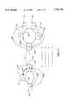
- FIG. 9is a diagram illustrating the divided LLC2 session with smart polling according to the present invention operating across a link between a leaf node and a central router in a Boundary Routing environment.
- FIG. 10shows another configuration, where a smart polling session is conducted between a leaf node and central router at a regional site.
- FIG. 11is a diagram of another configuration in which two LLC2 sessions are conducted between a leaf node and a regional central router according to the present invention.
- FIG. 12illustrates the case in which the LLC2 session is conducted in an IBM advanced-peer-to-peer networking APPN environment.
- FIGS. 5-7describe the basic structure of systems implementing the present invention
- FIGS. 9-11illustrate representative environments in which the present invention operates.
- the basic architecture of a system implementing the present inventionis shown in FIG. 5.
- the systemincludes a central node 200 which is connected across a communication link 201 to a leaf node 202.
- a local area network 203is connected to the central node 200.
- the local area network 203is represented by a ring.
- Other local area network configurationscan be utilized in this system.
- the local area network 203includes a first end station 204 and a second end station 205 which are labeled X and Y respectively.
- a leaf node 202is also coupled to a local area network 206. This local area network is also represented by a ring in the drawing. Other configurations of local area networks could be utilized.
- the local area network 206couples four end stations 207, 208, 209 and 210 labeled A, B, C and D respectively, to the leaf node 202.
- the central node 200might be implemented using a bridge/router system, a switch, or other network intermediate system. Devices in this class of devices are referred to as edge devices, as they provide interfaces between the link 201 and the local area network 203. Similarly, the leaf node 202 might be implemented with a bridge/router device, a bridge, or a switch. It may in a preferred embodiment implement the Boundary RoutingTM remote link architecture discussed above. This device is also referred to as an edge device as it provides an interface between the link 201 and the local area network 206.
- LLC2 trafficestablishes end-to-end connections between the end stations.
- a connection oriented sessioncould be established between end station X and end station A, between end station X and end station B, between end station Y and end station C, and between end station Y and end station D. All of these connection oriented sessions pass traffic across the link 201 through the edge devices 200 and 202.
- these connection oriented sessionsare divided into the first link session, an intermediate session and a second link session as illustrated in the figure.
- the session between station X and station Ais divided into a link session LSXA between the end station X and the central node 200.
- the session between X and Bis divided into a link session LSXB, and the intermediate session IS and a link session LSBX.
- the session between end station Y and end station Cis divided into a link session LSYC, the intermediate IS, and a link session LSCY.
- the session between end station Y and end station Dis divided into the link session LSYD, the intermediate session IS, and a link session LSDY.
- logical connection oriented sessionsare terminated in the edge devices 200 and 202 in order to manage the traffic across the link 201 by establishing a shared smart polling intermediate session IS according to the present invention.
- the intermediate session ISis managed such that the polling traffic from only one of the four connection oriented sessions described above is being conducted across the link 201 at a time.
- the polling traffic between the end stations and the edge devicesis maintained by the edge devices as if it was successfully being completed across the link.
- Other kinds of data involved in the connection oriented sessionsuch as information packets and set up packets are passed through the edge devices 200 and 202 between the end stations in a normal fashion.
- FIG. 6illustrates the logical organization of the end-to-end sessions for the configuration of FIG. 5.
- the end station Yis set up with two state machines, one state machine 220 for the link session between Y and C and another state machine 221 for the link session between Y and D.
- the end station Xis set up with two state machines as well.
- one state machine 222is set up for the link session between X and A
- at another state machine 223is set up for the link session between X and B.
- corresponding state machinesare set up on the side adjacent to end stations.
- a state machine 224is set up for the link session between Y and C in communication with the state machine 220.
- Link session state machine 225is set up for the session between Y and D and communicates with the state machine 221. Similar state machines 226 and 227 are set up to communicate with the state machines 222 and 223, respectively, for the sessions between X and A, and X and B. Inside the central node, corresponding intermediate session state machines 228, 229, 230 and 231 are set up for each of the end-to-end sessions. Thus, state machine 220 is set up for the session between Y and C, and communicates within the central node 200 with the state machine 224 across an interprocess messaging protocol represented by the arrow 232. Similarly the intermediate session 229 is set up for the end-to-end session between Y and D, and communicates with the link session state machine 225.
- the intermediate session state machine 230is set up for the end-to-end session between X and A and communicates with the link session state machine 226.
- Intermediate session state machine 231is set up for the end-to-end session between X and B and communicates with the link session state machine 227.
- the intermediate state machines 228, 229, 230 and 231are managed with the smart polling process represented by block 232 in FIG. 6, and described in more detail below.
- the intermediate session state machines 228-231communicate across the link 201 to the leaf node 202.
- the corresponding intermediate session state machines 248-251are set up for the end-to-end sessions between A and X, B and X, D and Y, and C and Y respectively.
- These four state machines 248-251are controlled by the smart polling management process represented by block 252.
- each of the end-to-end sessionsincludes a link session state machine.
- the session between A and Xincludes link session state machine 255.
- the session between B and Xincludes link session state machine 256.
- the session between D and Yincludes link session state machine 257.
- the session between C and Yincludes link session state machine 258.
- the link session state machines 255-258communicate with the intermediate state machines 248-251 within the leaf node across respective interprocess messaging channels.
- the link session state machines 255-258communicate with corresponding state machines at the end of stations A, B, C and D across the local area network, as illustrated in FIG. 5.
- a link session state machine 260is set up in end station A for the session between A and X.
- Link session state machine 261is set up in end station B for the session between B and X.
- Link session state machine 262is set up in end station D for the session between D and Y.
- link session state machine 263is set up in end station C for the end-to-end session between C and Y.
- the process for implementing independent state machines within the central node 200 and leaf node 202 for each of the end-to-end sessionsprovides for local switching for the message packets being transmitted in each end-to-end session.
- the session between any two stations, such as end station Y and end station Dis divided in to three independently terminated communication links.
- the first link in this session between Y and Dis represented by the arrow 280.
- the second linkis represented by the arrow 201, and the third link is represented by the arrow 281.
- the links represented by arrows 280 and 281are managed as if they were standard end-to-end sessions, terminating at the state machines 221 and 225, and at the state machines 257 and 262 respectively.
- All messagesexcept the receive ready RR messages and the reject messages according to the LLC2 standard, are passed by the interprocess communication channels from the state machine 257 to the state machine 250 or from the state machine 225 to the state machine 229 in this single end-to-end session.
- the supervisory messages receive ready RR and rejectare blocked by the smart polling process of the present invention.
- Other messagesare locally switched within the leaf node and central node to divide the session into three essentially independent sessions.
- FIG. 7represents the traffic flow for an end-to-end session according to the present invention.
- the trafficflows from state machine 221 to state machine 225.
- state machine 225From state machine 225 it is passed to state machine 229 within the central node.
- the link between the central node and the leaf nodeinvolves passing messages between state machines 229 and 250.
- State machine 250transfers messages to the state machine 257.
- State machine 257manages transfer of messages from the leaf node to the end station state machine 262.
- the sessionbegins with a SABME message originating in state machine 221 and transmitted across the network on line 20 to the central node.
- the central noderecognizes the SABME packet and sets up state machine 225.
- the messageis transmitted on line 21 in an interprocess channel to a state machine 229 which is also set up for the end-to-end session.
- This state machine 229transmits the packet across the link between the leaf node and the central node represented by arrow 22 to the leaf node, which sets up state machine 250 to receive the packet and state machine 257 to manage transmission of the packet to the end station.
- the packetis transmitted across interprocess message channel 23 to the state machine 257 which transmits it across the local area network on line 24 to the end station, which sets up state machine 262.
- Successful set up of the state machineis indicated by the UA packet transmitted across line 25 to state machine 257 which passes the packet on the interprocess channel 26 to state machine 250.
- State machine 250returns the packet across line 27 to state machine 229 at the central node which passes the packet on the interprocess channel 28 to state machine 225.
- State machine 225forwards the packet on line 29 to state machine 221 to establish the end-to-end session. At that point, the state machine 221 and state machine 225 begin a normal LLC2 session terminated at state machines 221 and 225, respectively.
- the state machine 221sends a receive ready RR poll on line 30 and receives an acknowledgement receive ready RR final on line 31. Later, an information packet Info(1) is transferred on line 32 to the state machine 225 which acknowledges receipt on line 33. If a polling time out occurs, a receive ready RR poll is sent from state machine 221 on line 34 to the state machine 225 which responds with a receive ready RR final packet on line 35. A subsequent time out results in a similar packet exchange across lines 36 and 37. State machine 221 may send a second information packet Info(2) on line 38. If it does not receive a timely acknowledgement, it sends a receive ready RR poll at a subsequent time on line 39.
- the state machine 225may then send a receive ready RR final and acknowledgement packet on line 40 to the state machine 221. More data and other messages are transferred between the two state machines. To terminate the session, one of the state machines sends the disconnect DISC message, such as the message across line 41. The state machine 225 responds to the messages on line 41 with an unnumbered acknowledgement UA across line 42 which breaks down the session. As can be seen, this data flow is basically the same data flow as is encountered in FIG. 2 starting with the SABME packet. Earlier packets in the interchange of FIG. 2 are passed through in the process of FIG. 7 just like the SABME packet and the UA packet.
- the interprocess channel between state machines 225 and 229 in the central nodeis managed by the smart polling process of the present invention. That is, all packets except for receive ready RR polls and reject packets are passed from state machine 225 to state machine 229 on an interprocess channel. Thus, the info packet Info(1) which is received on line 32 is passed on interprocess channel 50 from state machine 225 to 229. State machine 229 manages transfer of the packet to the leaf node independent of the state machine 225.
- the state machine 229After the UA packet on line 27 is transferred between the state machines 229 and 250 to set up the session, the state machine 229 sends a receive ready RR poll on line 51. State machine 250 responds with a receive ready RR final acknowledgement on line 52. If the Info(1) packet is received on the interprocess channel 50 prior to a time out, state machine 229 queues and sends out a packet on line 53 to the state machine 250. State machine 250 will issue a receive acknowledgement on line 54 when it successfully receives a packet. At the same time, it transfers the packet on an interprocess channel 55 to the state machine 257.
- the smart polling algorithm of the present inventionwill block the standard poll and not send the poll to the leaf node except in special circumstances as described below. Thus, receive ready RR poll time outs occur and the polls are not always sent as indicated by the returning arrows 56 and 57 in the state machine 229, and the returning arrow 58 in the state machine 250.
- the information packet Info(2) on line 38is received by the state machine 225 and passed on the interprocess channel 60 to state machine 229.
- State machine 229queues and sends out the packet on line 61 to the state machine 250 which transfers the information packet on the interprocess channel 62 to the state machine 257. If the state machine 229 does not receive a timely acknowledgement, it will send a receive ready RR poll on line 63 to the state machine 250. The state machine 250, if it successfully received the packet, will respond to the receive ready RR poll with an acknowledgement on line 64. More data and other messages can be transferred as indicated.
- the state machine 225receives the DISC packet from line 41, it transfers the message on the interprocess channel 65 to the state machine 229.
- State machine 229forwards this packet on line 66 to state machine 250 which transfers it on the interprocess channel 67 to the state machine 257.
- the disconnectis acknowledged by a UA packet on line 68 which is transferred on the interprocess message channel 69 to state machine 225.
- the session between the leaf node state machine 257 and the end station state machine 262operates as a standard LLC2 session.
- the state machine 257may send a receive ready RR poll on line 70.
- State machine 262responds with a receive ready RR final acknowledgement on line 71.
- the information packet Info(1)is received by the state machine 257, it is transferred on line 72 to state machine 262 which acknowledges receipt on line 73. If a time out occurs in the session between state machine 257 and 262, state machine 257 issues a receive ready RR poll as indicated on line 74.
- State machine 262responds with a receive ready RR final acknowledgement as indicated by arrow 75.
- another receive ready RR pollmay be sent as indicated on line 76, to which the state machine 262 sends an acknowledgement as indicated on line 77.
- state machine 257receives an information packet Info(2) from the interprocess channel 62, it forwards the packet on line 78 to the state machine 262 which acknowledges receipt of the packet as indicated on line 79. More data and other messages may be transferred between the state machines 257 and 262, until the disconnect message is transferred by the state machine 257 on line 80 to state machine 262, and state machine 262 acknowledges with the UA acknowledgement on line 81.
- This UA acknowledgement on line 81is transferred from state machine 257 across the interprocess channel 82 to state machine 250 which passes the packet down the line to terminate the end-to-end session.
- state machines 257 and 262there is no time out after sending information packet Info(2) on line 78, like the time out encountered in the session between state machines 221 and 225 after the transfer on line 38.
- the acknowledgement on line 79is received immediately by state machine 257.
- state machine 221 on the end station Ysends out a receive ready RR poll before receiving acknowledgement of the second information packet.
- This difference in the figureemphasizes the independence of the sessions between the end station and the central node, and between the leaf node and the end station.
- separately terminated end-to-end sessionsare managed between the end stations and the intermediate sessions.
- the intermediate sessionis managed using the smart polling process of the present invention to control the amount of polling traffic across the link between the two networks.
- the state machines 221, 225, 229, 250, 257 and 262are all standard LLC2 state machines as specified according to the standard.
- the state machines 225 and 229are modified only for the purposes of the smart polling algorithm as mentioned above. Receive ready RR polling messages and the reject messages received by the state machines 225 and 257 are not forwarded to the intermediate session state machines 229 and 250. Otherwise, all packets are passed between these sessions and transferred according to the normal rules of the LLC2 session being implemented.
- the only flow that is not sentis a receive ready RR polls. Further, the RR poll is not sent out only in one case: when the sender has no outstanding unacknowledged data.
- Info(2)is an example of data that is unacknowledged, and thus requires that the poll be sent represented by line 63.
- the smart polling control algorithm according to the present inventionoperates as follows:
- Port up/down statuswhen the hardware driver status at the WAN port of the edge device is port down, then all of the active LLC2 sessions are put in the normal polling state.
- the portFor a session to be placed in the smart polling state; first, the port must be up, second, it must be in the normal polling state; third, LLC2 session activity is present on the port; fourth, no unacknowledged data is outstanding for the session; and fifth, the session is not in a flow control state.
- the smart polling algorithmis of no benefit. For two sessions, the smart polling traffic is reduced by fifty percent. For thirty two sessions, the polling traffic is reduced by ninety six percent with this algorithm.
- the algorithmdetects the failures within an additional delay of two times of the poll time out, or the hardware detection time out which could be a few seconds. The algorithm result in cases, such as where a WAN link goes away or is noisy for only a short period of time causing the LLC2 session to be terminated at one end, but not the other end, which would not find out about the termination unless it were the current polling session. In such cases a worst case additional delay of the poll time out interval times the number of polling sessions that might occur for a given connection oriented session may happen before the failure is detected.
- FIG. 8illustrates the process executed by state machines in the edge devices to manage the polling traffic according to the process of FIGS. 6 and 7.
- the state machinebegins monitoring the poll timer maintained for each session.
- the process of FIG. 8begins when the poll timer expires for a current session SESS (block 300).
- the state machinedetermines whether the current session is in the smart polling state (block 301). If it is not in the smart polling state, then the process branches to block 302 where it sends a poll across the link to the other edge device. After sending the poll, the state machine waits for a timely reply across the link from the destination via the other edge device (block 303).
- the state machineIf a timely reply is received, then the state machine resets a smart session timer (a session timer maintained for the set of managed sessions), resets the poll timer for the current session, and places the current session in the smart polling state. Further, if the current session was not already in the smart polling state, the number of smart sessions being conducted #SS is incremented (block 304). After this process of block 304, then the state machine is done for this poll interval (block 305).
- a smart session timera session timer maintained for the set of managed sessions
- the state machinedetermines the number of smart sessions currently in process (block 306). This number of smart sessions is represented by the variable #SS in the figure.
- the algorithmdetermines the number of skipped polls for the current session #SP(SESS)(block 307).
- the state machinewill determine whether the number of smart sessions #SS is equal to the number of skipped polls for the current session #SP(SESS) at block 308. If the numbers match, such as if there are four connection oriented sessions which are placed in the smart polling state, and the current session has suffered blocked polls four times, then the algorithm branches to block 302, to send a poll for the current session across the link.
- the algorithmdetermines whether the smart session timer has expired (block 309). This smart session timer is set to about one to three times the normal polling timer for the protocol, depending upon a particular implementation. If the timer has expired, then the algorithm determines whether the current session is the session in the set of managed sessions that has been waiting longest since one of its polls was sent across the link (block 310). If the session timer has expired and the current session is the longest waiting session, then the algorithm branches to block 302 to send the poll across the link.
- the smart session timerhas not expired at block 309, or if the current session is not the longest waiting session a block 310, then the poll is blocked, the poll timer is reset for the current session, and the number of skipped sessions for the current session is incremented (block 311).
- the state machinealso replies to the source of the current poll, maintaining the connection oriented session alive. After block 311, then the algorithm is done (block 305) for the current poll interval.
- the algorithmproceeds to block 303 where a timely reply is awaited for the current session. If a timely reply is received, the algorithm branches to block 304 as before, resets the smart session timer and resets the session poll timer. If the current session is not already in the smart polling state, it is changed to that state as mentioned above.
- the current sessionexits the smart polling state, and the number of connection oriented sessions in the smart polling state is decremented (block 312).
- the algorithmdetermines whether two consecutive no reply events, involving different sessions in the managed set, have been detected (block 313). If two consecutive no reply events have not occurred, then the algorithm branches to block 305 and the current polling session is done. The current session will then be in the normal polling mode, and issue a polling request again, until the disconnect state is reached according to the standard protocol.
- the sequence of steps in blocks 306 through 310cause the polling session in the set of connection oriented sessions which are in the smart polling state to be changed in a round robin fashion. This ensures that each of the members of the set of connection oriented sessions in the smart polling state is utilized for the polling session in turn, confirming the connection through the remote edge device of the end station subject of that session with a regular process. It will be understood that other techniques could be utilized for determining whether the current session should be used as the polling session or not.
- the algorithmwaits for the session which has been longest waiting between polls. This does not result in a significant delay in sending a poll across the link, because the smart session timer tested in block 309 is shared by all members of the set of connection oriented sessions in the smart polling state. Thus, these sessions will, in turn, pass through block 310 in the normal processing, until the longest waiting session is encountered.
- connection oriented sessionswhich are in the smart polling state are taken out of the smart polling state when an information packet is sent by one of the end stations of the sessions. These connection oriented sessions will re-enter the smart polling state upon successful sending of a poll, by execution of the process of block 304.
- FIGS. 9-12illustrate environments in which the smart polling process of the present invention might be executed, focusing on IBM environments running NetBIOS or SNA systems, in which the edge devices utilized are running under the Boundary RoutingTM remote link architecture.
- IBM environments running NetBIOS or SNA systemsin which the edge devices utilized are running under the Boundary RoutingTM remote link architecture.
- other environmentscan take advantage of the present invention.
- FIG. 9shows the environment discussed above with respect to FIG. 1, improved by the smart polling process of the present invention.
- a central router 400such as the NetBuilder II provided by 3Com Corporation.
- a leaf node router 401is coupled to the central router 400 across a WAN link 402 under the Boundary RoutingTM remote link architecture, which appears to the central router as if it were a LAN port schematically represented by the loop 403.
- the leaf node 401is connected to a local area network 404 which includes an IBM 3174 cluster controller 405 and a plurality of IBM 3270 display terminals 406. Coupled to the central router 400 is a local area network 407 on which an IBM 3745 FEP 408 is connected.
- An IBM host system 409is connected to the IBM 3745 FEP 408.
- Logical link control Type 2 sessionsare implemented between the end stations on the network 404 and end stations on the network 407.
- a LLC2 session 410may be established between the IBM 3174 405 and IBM 3745 408 as shown in the figure.
- this logical LLC2 sessionis divided into a local link session 411 between the IBM 3174 cluster controller 405 and the leaf node 401.
- a local link session 412is established between the IBM 3745 FEP 408 and the central router 400.
- a smart polling intermediate session 413is established between the leaf node 401 and the central router 400.
- Both the leaf node 401 and the central router 400include a program which runs the smart polling algorithm discussed above with respect to FIG. 8.
- the leaf nodeincludes the smart polling switch 414 and the central router 400 includes the smart polling switch for 415.
- this configurationcan also be used in the NetBIOS environment, and in other environments where logical connection oriented sessions can be established between end stations communicating through edge devices, such as the 3Com NetBuilder Token Ring and the 3Com NetBuilder II discussed with reference to FIG. 9.
- the LLC2 sessionsare locally terminated at each NetBuilder, such as the leaf node NetBuilder 401 and the central router NetBuilder 400.
- One local LLC2 sessionis maintained between the FEP 408 and the central router 400.
- Another local sessionis maintained between the cluster controller 405 and the leaf node 401.
- An intermediate session 413is maintained between the two edge devices at the leaf node 401 and the central node 400. Data received on the intermediate session 413 is forwarded by the switch 414, 415 as appropriate to the corresponding local session 411, 412.
- These three sessionsthen provide the total logical end-to-end LLC2 session 410.
- the two local sessions 411, 412 and the intermediate session 413all use the same source and destination media and service access point SAP address.
- the end systemsdo not require address changes to implement the smart polling algorithm of the present invention.
- the LLC2 virtual ring numberis used for the local LAN sessions where the LAN's 407 and 404 (and virtual LAN 403) are Token Rings as is typical in IBM environments.
- the switches for 414 and 415operate like data link switches or tunneling ports, and thus provide the same promiscuous mode characteristics as appear on the Token Ring.
- FIG. 10illustrates another common configuration with a regional site.
- a logical LLC2 session 500is established between an IBM 3745 FEP 501 coupled to an IBM host 502, and a IBM 3174 cluster controller 503 coupled to IBM 3270 displays 504.
- the communication between these end stationsproceeds through a network having the configuration shown in FIG. 10.
- the cluster controller 503is connected to a Token Ring LAN 505.
- a 3Com NetBuilder Token Ring leaf node 506is coupled to the LAN 505.
- a smart polling switch 507is executed in the leaf node edge device 506 as discussed above.
- a local LLC2 session 508is established between the switch 507 and the cluster controller 503.
- the leaf node 506is connected across a WAN link 508 in a Boundary RoutingTM remote link configuration to a central router 509.
- the central routerincludes a smart polling switch 510.
- An intermediate LLC2 session 511is established between the switch 507 and the switch 510 across the WAN link 508.
- the regional router 510is coupled to a network represented by the Internet Protocol IP cloud 512.
- This IP cloud 512is coupled to a host site router 513 which may be implemented using a 3Com NetBuilder II.
- the switch 510communicates using a data link switching DLSw session 514 (IETF RFC 1434 or IETF RFC 1795 TCP/IP session) with the host site router 513.
- the host site router 513is also connected to a Token Ring LAN 515. This LAN is connected to the FEP 501 which participates in the LLC2 session 500.
- a local LLC2 session 516is established between the FEP 501 and the host site router 513 and coupled between the host site router 513 and the regional router 509 through the data link switching TCP/IP session 514 as shown in the figure.
- FIG. 11is an extension of the configuration shown in FIG. 10.
- the extension in FIG. 10consists of a local IBM 3745 FEP 550 which is coupled to a Token Ring LAN 551.
- the Token Ring LAN 551is connected directly to the regional router 509 in this embodiment.
- An IBM host 552is coupled to the FEP 550 according to the standard environment.
- a logical LLC2 session 553is maintained between the cluster controller 503 and the FEP 550. This session is maintained across the local link session 508, the intermediate session 511, and a local link session 554. These sessions are maintained by the switch 510 in the regional site router 509, and the switch 507 in the leaf router 506.
- Boundary RoutingTM remote link leaf nodescan be communicating through a central router, with smart polling exercised across one or both of the wide area links with that central router.
- FIG. 12illustrates an alternative configuration in which an advanced peer-to-peer network APPN node is running in the central router.
- an APPN node 600is running in a central router 601.
- a leaf node 602, and a station, such as an IBM AS/400 computer 603,are in communication across a local area network 604.
- a logical LLC2 session 605is established between the APPN node 600 and the end station 603 at the leaf. Communication between the leaf node 602 and the central router 601 is established across a wide area network link 606, which is configured in this example in the Boundary RoutingTM remote link architecture configuration.
- the logical LLC2 session 605is divided into a local session 607, an intermediate session 608, and a local session 609.
- the local session 609is executed within the central router 601.
- the connection of the end destination to the edge deviceis through a virtual data link switching port in this example, or otherwise carried out in the software of the central router.
- the edge device and end stationmay be in a single processing system with or without other network intermediate system functionality.
- the present inventionprovides an algorithm which reduces the amount of polling traffic needed to keep connection oriented protocol sessions alive, when the traffic is flowing between two connected devices.
- the examples describedinvolve the Boundary RoutingTM remote link architecture, in which the edge devices communicate across a WAN link.
- Other communication mediamight be substituted within the spirit of the present invention.
- the edge devicesmay be connected to each other across a virtual LAN ATM backbone network, a local area network link, or other types of communication media.
- the inventionis particularly suited to logical link control layer connection oriented sessions in the IBM environment where SNA or NetBIOS are prevalent network operating protocols. However, it is extendable to any LLC layer or higher layer connection oriented session in which the physical traffic across the link between edge devices can be managed with smart polling.
Landscapes
- Engineering & Computer Science (AREA)
- Computer Networks & Wireless Communication (AREA)
- Signal Processing (AREA)
- Computer Security & Cryptography (AREA)
- Communication Control (AREA)
Abstract
Description
Claims (36)
Priority Applications (1)
| Application Number | Priority Date | Filing Date | Title |
|---|---|---|---|
| US08/594,878US5781726A (en) | 1996-01-31 | 1996-01-31 | Management of polling traffic in connection oriented protocol sessions |
Applications Claiming Priority (1)
| Application Number | Priority Date | Filing Date | Title |
|---|---|---|---|
| US08/594,878US5781726A (en) | 1996-01-31 | 1996-01-31 | Management of polling traffic in connection oriented protocol sessions |
Publications (1)
| Publication Number | Publication Date |
|---|---|
| US5781726Atrue US5781726A (en) | 1998-07-14 |
Family
ID=24380787
Family Applications (1)
| Application Number | Title | Priority Date | Filing Date |
|---|---|---|---|
| US08/594,878Expired - LifetimeUS5781726A (en) | 1996-01-31 | 1996-01-31 | Management of polling traffic in connection oriented protocol sessions |
Country Status (1)
| Country | Link |
|---|---|
| US (1) | US5781726A (en) |
Cited By (69)
| Publication number | Priority date | Publication date | Assignee | Title |
|---|---|---|---|---|
| US5991302A (en)* | 1997-04-10 | 1999-11-23 | Cisco Technology, Inc. | Technique for maintaining prioritization of data transferred among heterogeneous nodes of a computer network |
| US6084879A (en)* | 1997-04-10 | 2000-07-04 | Cisco Technology, Inc. | Technique for capturing information needed to implement transmission priority routing among heterogeneous nodes of a computer network |
| US6098067A (en)* | 1997-05-02 | 2000-08-01 | Kabushiki Kaisha Toshiba | Remote computer management system |
| US6105064A (en)* | 1997-05-30 | 2000-08-15 | Novell, Inc. | System for placing packets on network for transmission from sending endnode to receiving endnode at times which are determined by window size and metering interval |
| US6147989A (en)* | 1993-04-20 | 2000-11-14 | Kabushiki Kaisha Toshiba | ATM communication system with high speed connection-less service function |
| KR20010028832A (en)* | 1999-09-27 | 2001-04-06 | 최항석 | System for provoding services based on connection-oriented protocol in the web service based on connection-less protocol |
| US6289502B1 (en)* | 1997-09-26 | 2001-09-11 | Massachusetts Institute Of Technology | Model-based software design and validation |
| US20020064137A1 (en)* | 2000-11-16 | 2002-05-30 | Garakani Mehryar Khalili | Synchronization of V42bis de/compression for V34/V42 modem relay method and apparatus |
| US6434141B1 (en) | 1999-05-26 | 2002-08-13 | Bigband Networks, Inc. | Communication management system and method |
| US6446126B1 (en)* | 1997-03-28 | 2002-09-03 | Honeywell International Inc. | Ripple scheduling for end-to-end global resource management |
| US6457051B1 (en)* | 1997-11-25 | 2002-09-24 | Packeteer, Inc. | Method for automatically classifying traffic in a pocket communications network |
| US6463475B1 (en)* | 1997-09-26 | 2002-10-08 | 3Com Corporation | Method and device for tunnel switching |
| US6591299B2 (en)* | 1997-11-25 | 2003-07-08 | Packeteer, Inc. | Method for automatically classifying traffic with enhanced hierarchy in a packet communications network |
| US6757250B1 (en)* | 1999-04-12 | 2004-06-29 | Mindspeed Technologies, Inc. | Methods and apparatus for data communications through packet networks |
| US6791979B1 (en) | 1997-04-10 | 2004-09-14 | Cisco Technology, Inc. | Mechanism for conveying data prioritization information among heterogeneous nodes of a computer network |
| US20050021699A1 (en)* | 2003-06-27 | 2005-01-27 | Newisys, Inc. | Dynamic multiple cluster system reconfiguration |
| US6868097B1 (en)* | 1999-01-28 | 2005-03-15 | Mitsubishi Denki Kabushiki Kaisha | Communication network, and master device, slave device, multiplexer and switch constituting the communication network |
| US20050108250A1 (en)* | 2000-12-28 | 2005-05-19 | Microsoft Corporation | Stateless distributed computer architecture with server-oriented state-caching objects maintained on network or client |
| US20060036730A1 (en)* | 2004-08-06 | 2006-02-16 | Richard Graham | System and method for address block enhanced dynamic network policy management |
| US20060062159A1 (en)* | 2000-12-29 | 2006-03-23 | Intel Corporation, A Delaware Corporation | Determining the presence of IP multicast routers |
| US20060098630A1 (en)* | 2000-12-21 | 2006-05-11 | Reba Technologies, Inc. | Method and system for communicating an information packet through multiple router devices |
| US20060193341A1 (en)* | 1999-09-21 | 2006-08-31 | Ntt Docomo, Inc. | Data conversion apparatus, signal, data conversion method, dce, gateway and communication apparatus |
| US20060277187A1 (en)* | 2002-03-01 | 2006-12-07 | Roese John J | Location based data |
| US7151782B1 (en) | 2005-08-09 | 2006-12-19 | Bigband Networks, Inc. | Method and system for providing multiple services to end-users |
| US20070061470A1 (en)* | 2000-12-21 | 2007-03-15 | Berg Mitchell T | Method and system for selecting a computing device for maintaining a client session in response to a request packet |
| US20070067046A1 (en)* | 2000-12-21 | 2007-03-22 | Berg Mitchell T | Method and system for communicating an information packet through multiple networks |
| US20070255716A1 (en)* | 2006-04-28 | 2007-11-01 | Sap Ag | Timer service computer program components |
| WO2008138198A1 (en) | 2007-05-11 | 2008-11-20 | Huawei Technologies Co., Ltd. | Keepalive monitoring method, system and apparatus of a subscriber session |
| WO2008141572A1 (en) | 2007-05-21 | 2008-11-27 | Huawei Technologies Co., Ltd. | Method and system for performing keepalive monitoring on client sessions |
| US7512686B2 (en) | 2000-12-21 | 2009-03-31 | Berg Mitchell T | Method and system for establishing a data structure of a connection with a client |
| US7539198B1 (en)* | 2002-06-26 | 2009-05-26 | Cisco Technology, Inc. | System and method to provide node-to-node connectivity in a communications network |
| US7546369B2 (en) | 2000-12-21 | 2009-06-09 | Berg Mitchell T | Method and system for communicating a request packet in response to a state |
| US7580403B2 (en) | 2004-02-26 | 2009-08-25 | Enterasys Networks, Inc. | Status transmission system and method |
| US7611292B2 (en) | 2004-11-08 | 2009-11-03 | Enterasys Networks, Inc. | Optical interface identification system |
| US7647422B2 (en) | 2001-11-06 | 2010-01-12 | Enterasys Networks, Inc. | VPN failure recovery |
| US20100039956A1 (en)* | 2007-05-21 | 2010-02-18 | Huawei Technologies Co., Ltd. | Method and system for performing keep-alive monitoring on subscriber sessions |
| US7779134B1 (en) | 2003-02-25 | 2010-08-17 | Cisco Technology, Inc. | Using modem profiles to improve connectivity, connect timing, and compression performance on a modem relay (MR) gateway |
| US8086232B2 (en) | 2005-06-28 | 2011-12-27 | Enterasys Networks, Inc. | Time synchronized wireless method and operations |
| US8156209B1 (en)* | 2001-02-15 | 2012-04-10 | Cisco Technology, Inc. | Aggregation devices processing keep-alive messages of point-to-point sessions |
| US20120269089A1 (en)* | 2006-08-22 | 2012-10-25 | Morrill Robert J | System and method for monitoring interlayer devices and optimizing network performance |
| US8477614B2 (en) | 2006-06-30 | 2013-07-02 | Centurylink Intellectual Property Llc | System and method for routing calls if potential call paths are impaired or congested |
| US8488447B2 (en) | 2006-06-30 | 2013-07-16 | Centurylink Intellectual Property Llc | System and method for adjusting code speed in a transmission path during call set-up due to reduced transmission performance |
| US8488495B2 (en) | 2006-08-22 | 2013-07-16 | Centurylink Intellectual Property Llc | System and method for routing communications between packet networks based on real time pricing |
| US8509082B2 (en) | 2006-08-22 | 2013-08-13 | Centurylink Intellectual Property Llc | System and method for load balancing network resources using a connection admission control engine |
| US8520603B2 (en) | 2006-08-22 | 2013-08-27 | Centurylink Intellectual Property Llc | System and method for monitoring and optimizing network performance to a wireless device |
| US8531954B2 (en) | 2006-08-22 | 2013-09-10 | Centurylink Intellectual Property Llc | System and method for handling reservation requests with a connection admission control engine |
| US8537695B2 (en) | 2006-08-22 | 2013-09-17 | Centurylink Intellectual Property Llc | System and method for establishing a call being received by a trunk on a packet network |
| US8549405B2 (en) | 2006-08-22 | 2013-10-01 | Centurylink Intellectual Property Llc | System and method for displaying a graphical representation of a network to identify nodes and node segments on the network that are not operating normally |
| US8576722B2 (en) | 2006-08-22 | 2013-11-05 | Centurylink Intellectual Property Llc | System and method for modifying connectivity fault management packets |
| US8619820B2 (en) | 2006-08-22 | 2013-12-31 | Centurylink Intellectual Property Llc | System and method for enabling communications over a number of packet networks |
| US8619596B2 (en) | 2006-08-22 | 2013-12-31 | Centurylink Intellectual Property Llc | System and method for using centralized network performance tables to manage network communications |
| US8619600B2 (en) | 2006-08-22 | 2013-12-31 | Centurylink Intellectual Property Llc | System and method for establishing calls over a call path having best path metrics |
| US8670313B2 (en) | 2006-08-22 | 2014-03-11 | Centurylink Intellectual Property Llc | System and method for adjusting the window size of a TCP packet through network elements |
| US8687614B2 (en) | 2006-08-22 | 2014-04-01 | Centurylink Intellectual Property Llc | System and method for adjusting radio frequency parameters |
| US8717911B2 (en) | 2006-06-30 | 2014-05-06 | Centurylink Intellectual Property Llc | System and method for collecting network performance information |
| US8743703B2 (en) | 2006-08-22 | 2014-06-03 | Centurylink Intellectual Property Llc | System and method for tracking application resource usage |
| US8743700B2 (en) | 2006-08-22 | 2014-06-03 | Centurylink Intellectual Property Llc | System and method for provisioning resources of a packet network based on collected network performance information |
| US8750158B2 (en) | 2006-08-22 | 2014-06-10 | Centurylink Intellectual Property Llc | System and method for differentiated billing |
| US8811160B2 (en) | 2006-08-22 | 2014-08-19 | Centurylink Intellectual Property Llc | System and method for routing data on a packet network |
| US8879391B2 (en) | 2008-04-09 | 2014-11-04 | Centurylink Intellectual Property Llc | System and method for using network derivations to determine path states |
| US9094257B2 (en) | 2006-06-30 | 2015-07-28 | Centurylink Intellectual Property Llc | System and method for selecting a content delivery network |
| US9112734B2 (en) | 2006-08-22 | 2015-08-18 | Centurylink Intellectual Property Llc | System and method for generating a graphical user interface representative of network performance |
| US9225609B2 (en) | 2006-08-22 | 2015-12-29 | Centurylink Intellectual Property Llc | System and method for remotely controlling network operators |
| US9241271B2 (en) | 2006-08-22 | 2016-01-19 | Centurylink Intellectual Property Llc | System and method for restricting access to network performance information |
| US9479341B2 (en) | 2006-08-22 | 2016-10-25 | Centurylink Intellectual Property Llc | System and method for initiating diagnostics on a packet network node |
| US9521150B2 (en) | 2006-10-25 | 2016-12-13 | Centurylink Intellectual Property Llc | System and method for automatically regulating messages between networks |
| US9621361B2 (en) | 2006-08-22 | 2017-04-11 | Centurylink Intellectual Property Llc | Pin-hole firewall for communicating data packets on a packet network |
| US9660761B2 (en) | 2006-10-19 | 2017-05-23 | Centurylink Intellectual Property Llc | System and method for monitoring a connection of an end-user device to a network |
| US9832090B2 (en) | 2006-08-22 | 2017-11-28 | Centurylink Intellectual Property Llc | System, method for compiling network performancing information for communications with customer premise equipment |
Citations (11)
| Publication number | Priority date | Publication date | Assignee | Title |
|---|---|---|---|---|
| US5237693A (en)* | 1990-04-04 | 1993-08-17 | Sharp Kabushiki Kaisha | System for accessing peripheral devices connected in network |
| US5303238A (en)* | 1990-12-11 | 1994-04-12 | International Business Machines Corporation | Network communications intermediate interface |
| US5309437A (en)* | 1990-06-29 | 1994-05-03 | Digital Equipment Corporation | Bridge-like internet protocol router |
| US5341498A (en)* | 1990-04-16 | 1994-08-23 | Motorola, Inc. | Database management system having first and second databases for automatically modifying storage structure of second database when storage structure of first database is modified |
| US5412803A (en)* | 1992-02-20 | 1995-05-02 | International Business Machines Corporation | Communications system having plurality of originator and corresponding recipient buffers with each buffer having three different logical areas for transmitting messages in single transfer |
| US5414700A (en)* | 1990-01-22 | 1995-05-09 | Digital Equipment Corp. | Negotiation protocol for establishment of full duplex communication on a token ring network |
| US5423002A (en)* | 1992-04-20 | 1995-06-06 | 3Com Corporation | System for extending network resources to remote networks |
| US5467351A (en)* | 1994-04-22 | 1995-11-14 | At&T Corp. | Extendible round robin local area hub network |
| US5469438A (en)* | 1994-01-28 | 1995-11-21 | At&T Ipm Corp. | Method of transmitting signals in an extendible local area network |
| US5541911A (en)* | 1994-10-12 | 1996-07-30 | 3Com Corporation | Remote smart filtering communication management system |
| US5553073A (en)* | 1993-05-17 | 1996-09-03 | Ibm Corporation | Token ring network |
- 1996
- 1996-01-31USUS08/594,878patent/US5781726A/ennot_activeExpired - Lifetime
Patent Citations (11)
| Publication number | Priority date | Publication date | Assignee | Title |
|---|---|---|---|---|
| US5414700A (en)* | 1990-01-22 | 1995-05-09 | Digital Equipment Corp. | Negotiation protocol for establishment of full duplex communication on a token ring network |
| US5237693A (en)* | 1990-04-04 | 1993-08-17 | Sharp Kabushiki Kaisha | System for accessing peripheral devices connected in network |
| US5341498A (en)* | 1990-04-16 | 1994-08-23 | Motorola, Inc. | Database management system having first and second databases for automatically modifying storage structure of second database when storage structure of first database is modified |
| US5309437A (en)* | 1990-06-29 | 1994-05-03 | Digital Equipment Corporation | Bridge-like internet protocol router |
| US5303238A (en)* | 1990-12-11 | 1994-04-12 | International Business Machines Corporation | Network communications intermediate interface |
| US5412803A (en)* | 1992-02-20 | 1995-05-02 | International Business Machines Corporation | Communications system having plurality of originator and corresponding recipient buffers with each buffer having three different logical areas for transmitting messages in single transfer |
| US5423002A (en)* | 1992-04-20 | 1995-06-06 | 3Com Corporation | System for extending network resources to remote networks |
| US5553073A (en)* | 1993-05-17 | 1996-09-03 | Ibm Corporation | Token ring network |
| US5469438A (en)* | 1994-01-28 | 1995-11-21 | At&T Ipm Corp. | Method of transmitting signals in an extendible local area network |
| US5467351A (en)* | 1994-04-22 | 1995-11-14 | At&T Corp. | Extendible round robin local area hub network |
| US5541911A (en)* | 1994-10-12 | 1996-07-30 | 3Com Corporation | Remote smart filtering communication management system |
Non-Patent Citations (2)
| Title |
|---|
| IBM, "Token-Ring Network: Architecture Reference", Selected Chapters, 1989. |
| IBM, Token Ring Network: Architecture Reference , Selected Chapters, 1989.* |
Cited By (128)
| Publication number | Priority date | Publication date | Assignee | Title |
|---|---|---|---|---|
| US6147989A (en)* | 1993-04-20 | 2000-11-14 | Kabushiki Kaisha Toshiba | ATM communication system with high speed connection-less service function |
| US6446126B1 (en)* | 1997-03-28 | 2002-09-03 | Honeywell International Inc. | Ripple scheduling for end-to-end global resource management |
| US6084879A (en)* | 1997-04-10 | 2000-07-04 | Cisco Technology, Inc. | Technique for capturing information needed to implement transmission priority routing among heterogeneous nodes of a computer network |
| US5991302A (en)* | 1997-04-10 | 1999-11-23 | Cisco Technology, Inc. | Technique for maintaining prioritization of data transferred among heterogeneous nodes of a computer network |
| US6791979B1 (en) | 1997-04-10 | 2004-09-14 | Cisco Technology, Inc. | Mechanism for conveying data prioritization information among heterogeneous nodes of a computer network |
| US6098067A (en)* | 1997-05-02 | 2000-08-01 | Kabushiki Kaisha Toshiba | Remote computer management system |
| US6105064A (en)* | 1997-05-30 | 2000-08-15 | Novell, Inc. | System for placing packets on network for transmission from sending endnode to receiving endnode at times which are determined by window size and metering interval |
| US6289502B1 (en)* | 1997-09-26 | 2001-09-11 | Massachusetts Institute Of Technology | Model-based software design and validation |
| US6463475B1 (en)* | 1997-09-26 | 2002-10-08 | 3Com Corporation | Method and device for tunnel switching |
| US6591299B2 (en)* | 1997-11-25 | 2003-07-08 | Packeteer, Inc. | Method for automatically classifying traffic with enhanced hierarchy in a packet communications network |
| US6457051B1 (en)* | 1997-11-25 | 2002-09-24 | Packeteer, Inc. | Method for automatically classifying traffic in a pocket communications network |
| US6868097B1 (en)* | 1999-01-28 | 2005-03-15 | Mitsubishi Denki Kabushiki Kaisha | Communication network, and master device, slave device, multiplexer and switch constituting the communication network |
| US7957369B2 (en)* | 1999-04-12 | 2011-06-07 | Mindspeed Technologies, Inc. | Methods and apparatus for data communications through packet networks |
| US7697539B1 (en)* | 1999-04-12 | 2010-04-13 | Mindspeed Technologies, Inc. | Methods and apparatus for data communications through packet networks |
| US20100158027A1 (en)* | 1999-04-12 | 2010-06-24 | Conexant Systems, Inc. | Methods and apparatus for data communications through packet networks |
| US6757250B1 (en)* | 1999-04-12 | 2004-06-29 | Mindspeed Technologies, Inc. | Methods and apparatus for data communications through packet networks |
| US6434141B1 (en) | 1999-05-26 | 2002-08-13 | Bigband Networks, Inc. | Communication management system and method |
| US7120142B1 (en) | 1999-05-26 | 2006-10-10 | Bigband Networks, Inc. | Communication management system and method |
| US7031301B1 (en) | 1999-05-26 | 2006-04-18 | Bigband Networks, Inc. | Communication management system and method |
| US7113502B2 (en) | 1999-05-26 | 2006-09-26 | Bigband Networks, Inc. | Communication management system and method |
| US20060193341A1 (en)* | 1999-09-21 | 2006-08-31 | Ntt Docomo, Inc. | Data conversion apparatus, signal, data conversion method, dce, gateway and communication apparatus |
| US7680122B2 (en)* | 1999-09-21 | 2010-03-16 | Ntt Docomo, Inc. | Communication method for data communication based on point-to-point protocol |
| KR20010028832A (en)* | 1999-09-27 | 2001-04-06 | 최항석 | System for provoding services based on connection-oriented protocol in the web service based on connection-less protocol |
| US7113501B2 (en)* | 2000-11-16 | 2006-09-26 | Cisco Technology, Inc. | Synchronization of V42bis de/compression for V34/V42 modem relay method and apparatus |
| US20020064137A1 (en)* | 2000-11-16 | 2002-05-30 | Garakani Mehryar Khalili | Synchronization of V42bis de/compression for V34/V42 modem relay method and apparatus |
| US20070061470A1 (en)* | 2000-12-21 | 2007-03-15 | Berg Mitchell T | Method and system for selecting a computing device for maintaining a client session in response to a request packet |
| US7546369B2 (en) | 2000-12-21 | 2009-06-09 | Berg Mitchell T | Method and system for communicating a request packet in response to a state |
| US8341290B2 (en) | 2000-12-21 | 2012-12-25 | Noatak Software Llc | Method and system for selecting a computing device for maintaining a client session in response to a request packet |
| US20070067046A1 (en)* | 2000-12-21 | 2007-03-22 | Berg Mitchell T | Method and system for communicating an information packet through multiple networks |
| US20070086360A1 (en)* | 2000-12-21 | 2007-04-19 | Berg Mitchell T | Method and system for communicating an information packet through multiple router devices |
| US20060098630A1 (en)* | 2000-12-21 | 2006-05-11 | Reba Technologies, Inc. | Method and system for communicating an information packet through multiple router devices |
| US9100409B2 (en) | 2000-12-21 | 2015-08-04 | Noatak Software Llc | Method and system for selecting a computing device for maintaining a client session in response to a request packet |
| US7649876B2 (en) | 2000-12-21 | 2010-01-19 | Berg Mitchell T | Method and system for communicating an information packet through multiple router devices |
| US7506063B2 (en) | 2000-12-21 | 2009-03-17 | Noatak Software Llc | Method and system for initiating execution of software in response to a state |
| US7512686B2 (en) | 2000-12-21 | 2009-03-31 | Berg Mitchell T | Method and system for establishing a data structure of a connection with a client |
| US7640298B2 (en)* | 2000-12-21 | 2009-12-29 | Berg Mitchell T | Method and system for communicating an information packet through multiple router devices |
| US8161163B2 (en)* | 2000-12-28 | 2012-04-17 | Microsoft Corporation | Stateless distributed computer architecture with server-oriented state-caching objects maintained on network or client |
| US20050108250A1 (en)* | 2000-12-28 | 2005-05-19 | Microsoft Corporation | Stateless distributed computer architecture with server-oriented state-caching objects maintained on network or client |
| US20060062159A1 (en)* | 2000-12-29 | 2006-03-23 | Intel Corporation, A Delaware Corporation | Determining the presence of IP multicast routers |
| US7660268B2 (en)* | 2000-12-29 | 2010-02-09 | Intel Corporation | Determining the presence of IP multicast routers |
| US8156209B1 (en)* | 2001-02-15 | 2012-04-10 | Cisco Technology, Inc. | Aggregation devices processing keep-alive messages of point-to-point sessions |
| US7647422B2 (en) | 2001-11-06 | 2010-01-12 | Enterasys Networks, Inc. | VPN failure recovery |
| US20060277187A1 (en)* | 2002-03-01 | 2006-12-07 | Roese John J | Location based data |
| US7706369B2 (en) | 2002-03-01 | 2010-04-27 | Enterasys Networks, Inc. | Location discovery in a data network |
| US8972589B2 (en) | 2002-03-01 | 2015-03-03 | Enterasys Networks, Inc. | Location-based access control in a data network |
| US7606938B2 (en) | 2002-03-01 | 2009-10-20 | Enterasys Networks, Inc. | Verified device locations in a data network |
| US7739402B2 (en) | 2002-03-01 | 2010-06-15 | Enterasys Networks, Inc. | Locating devices in a data network |
| US7539198B1 (en)* | 2002-06-26 | 2009-05-26 | Cisco Technology, Inc. | System and method to provide node-to-node connectivity in a communications network |
| US7779134B1 (en) | 2003-02-25 | 2010-08-17 | Cisco Technology, Inc. | Using modem profiles to improve connectivity, connect timing, and compression performance on a modem relay (MR) gateway |
| US20050021699A1 (en)* | 2003-06-27 | 2005-01-27 | Newisys, Inc. | Dynamic multiple cluster system reconfiguration |
| WO2005003893A3 (en)* | 2003-06-27 | 2007-02-15 | Newisys Inc | Dynamic multiple cluster system reconfiguration |
| US7577727B2 (en)* | 2003-06-27 | 2009-08-18 | Newisys, Inc. | Dynamic multiple cluster system reconfiguration |
| US7580403B2 (en) | 2004-02-26 | 2009-08-25 | Enterasys Networks, Inc. | Status transmission system and method |
| US20060036730A1 (en)* | 2004-08-06 | 2006-02-16 | Richard Graham | System and method for address block enhanced dynamic network policy management |
| US7945945B2 (en) | 2004-08-06 | 2011-05-17 | Enterasys Networks, Inc. | System and method for address block enhanced dynamic network policy management |
| US7611292B2 (en) | 2004-11-08 | 2009-11-03 | Enterasys Networks, Inc. | Optical interface identification system |
| US8086232B2 (en) | 2005-06-28 | 2011-12-27 | Enterasys Networks, Inc. | Time synchronized wireless method and operations |
| US7151782B1 (en) | 2005-08-09 | 2006-12-19 | Bigband Networks, Inc. | Method and system for providing multiple services to end-users |
| US20070255716A1 (en)* | 2006-04-28 | 2007-11-01 | Sap Ag | Timer service computer program components |
| US8046731B2 (en)* | 2006-04-28 | 2011-10-25 | Sap Ag | Timer service computer program components |
| US9549004B2 (en) | 2006-06-30 | 2017-01-17 | Centurylink Intellectual Property Llc | System and method for re-routing calls |
| US9154634B2 (en) | 2006-06-30 | 2015-10-06 | Centurylink Intellectual Property Llc | System and method for managing network communications |
| US9749399B2 (en) | 2006-06-30 | 2017-08-29 | Centurylink Intellectual Property Llc | System and method for selecting a content delivery network |
| US8570872B2 (en) | 2006-06-30 | 2013-10-29 | Centurylink Intellectual Property Llc | System and method for selecting network ingress and egress |
| US10560494B2 (en) | 2006-06-30 | 2020-02-11 | Centurylink Intellectual Property Llc | Managing voice over internet protocol (VoIP) communications |
| US9118583B2 (en) | 2006-06-30 | 2015-08-25 | Centurylink Intellectual Property Llc | System and method for re-routing calls |
| US8477614B2 (en) | 2006-06-30 | 2013-07-02 | Centurylink Intellectual Property Llc | System and method for routing calls if potential call paths are impaired or congested |
| US8488447B2 (en) | 2006-06-30 | 2013-07-16 | Centurylink Intellectual Property Llc | System and method for adjusting code speed in a transmission path during call set-up due to reduced transmission performance |
| US9838440B2 (en) | 2006-06-30 | 2017-12-05 | Centurylink Intellectual Property Llc | Managing voice over internet protocol (VoIP) communications |
| US9094257B2 (en) | 2006-06-30 | 2015-07-28 | Centurylink Intellectual Property Llc | System and method for selecting a content delivery network |
| US9054915B2 (en) | 2006-06-30 | 2015-06-09 | Centurylink Intellectual Property Llc | System and method for adjusting CODEC speed in a transmission path during call set-up due to reduced transmission performance |
| US8976665B2 (en) | 2006-06-30 | 2015-03-10 | Centurylink Intellectual Property Llc | System and method for re-routing calls |
| US10230788B2 (en) | 2006-06-30 | 2019-03-12 | Centurylink Intellectual Property Llc | System and method for selecting a content delivery network |
| US8717911B2 (en) | 2006-06-30 | 2014-05-06 | Centurylink Intellectual Property Llc | System and method for collecting network performance information |
| US20120269089A1 (en)* | 2006-08-22 | 2012-10-25 | Morrill Robert J | System and method for monitoring interlayer devices and optimizing network performance |
| US9225646B2 (en) | 2006-08-22 | 2015-12-29 | Centurylink Intellectual Property Llc | System and method for improving network performance using a connection admission control engine |
| US8576722B2 (en) | 2006-08-22 | 2013-11-05 | Centurylink Intellectual Property Llc | System and method for modifying connectivity fault management packets |
| US8619820B2 (en) | 2006-08-22 | 2013-12-31 | Centurylink Intellectual Property Llc | System and method for enabling communications over a number of packet networks |
| US8619596B2 (en) | 2006-08-22 | 2013-12-31 | Centurylink Intellectual Property Llc | System and method for using centralized network performance tables to manage network communications |
| US8619600B2 (en) | 2006-08-22 | 2013-12-31 | Centurylink Intellectual Property Llc | System and method for establishing calls over a call path having best path metrics |
| US8670313B2 (en) | 2006-08-22 | 2014-03-11 | Centurylink Intellectual Property Llc | System and method for adjusting the window size of a TCP packet through network elements |
| US8687614B2 (en) | 2006-08-22 | 2014-04-01 | Centurylink Intellectual Property Llc | System and method for adjusting radio frequency parameters |
| US8549405B2 (en) | 2006-08-22 | 2013-10-01 | Centurylink Intellectual Property Llc | System and method for displaying a graphical representation of a network to identify nodes and node segments on the network that are not operating normally |
| US8743703B2 (en) | 2006-08-22 | 2014-06-03 | Centurylink Intellectual Property Llc | System and method for tracking application resource usage |
| US8743700B2 (en) | 2006-08-22 | 2014-06-03 | Centurylink Intellectual Property Llc | System and method for provisioning resources of a packet network based on collected network performance information |
| US8750158B2 (en) | 2006-08-22 | 2014-06-10 | Centurylink Intellectual Property Llc | System and method for differentiated billing |
| US8811160B2 (en) | 2006-08-22 | 2014-08-19 | Centurylink Intellectual Property Llc | System and method for routing data on a packet network |
| US10469385B2 (en) | 2006-08-22 | 2019-11-05 | Centurylink Intellectual Property Llc | System and method for improving network performance using a connection admission control engine |
| US8537695B2 (en) | 2006-08-22 | 2013-09-17 | Centurylink Intellectual Property Llc | System and method for establishing a call being received by a trunk on a packet network |
| US8531954B2 (en) | 2006-08-22 | 2013-09-10 | Centurylink Intellectual Property Llc | System and method for handling reservation requests with a connection admission control engine |
| US9014204B2 (en) | 2006-08-22 | 2015-04-21 | Centurylink Intellectual Property Llc | System and method for managing network communications |
| US9042370B2 (en) | 2006-08-22 | 2015-05-26 | Centurylink Intellectual Property Llc | System and method for establishing calls over a call path having best path metrics |
| US8520603B2 (en) | 2006-08-22 | 2013-08-27 | Centurylink Intellectual Property Llc | System and method for monitoring and optimizing network performance to a wireless device |
| US9054986B2 (en) | 2006-08-22 | 2015-06-09 | Centurylink Intellectual Property Llc | System and method for enabling communications over a number of packet networks |
| US8509082B2 (en) | 2006-08-22 | 2013-08-13 | Centurylink Intellectual Property Llc | System and method for load balancing network resources using a connection admission control engine |
| US9094261B2 (en) | 2006-08-22 | 2015-07-28 | Centurylink Intellectual Property Llc | System and method for establishing a call being received by a trunk on a packet network |
| US8488495B2 (en) | 2006-08-22 | 2013-07-16 | Centurylink Intellectual Property Llc | System and method for routing communications between packet networks based on real time pricing |
| US9112734B2 (en) | 2006-08-22 | 2015-08-18 | Centurylink Intellectual Property Llc | System and method for generating a graphical user interface representative of network performance |
| US8472326B2 (en)* | 2006-08-22 | 2013-06-25 | Centurylink Intellectual Property Llc | System and method for monitoring interlayer devices and optimizing network performance |
| US10348594B2 (en) | 2006-08-22 | 2019-07-09 | Centurylink Intellectual Property Llc | Monitoring performance of voice over internet protocol (VoIP) networks |
| US9225609B2 (en) | 2006-08-22 | 2015-12-29 | Centurylink Intellectual Property Llc | System and method for remotely controlling network operators |
| US20130286875A1 (en)* | 2006-08-22 | 2013-10-31 | CenturyLink Intellectual Property LLP | System and method for improving network performance |
| US9240906B2 (en) | 2006-08-22 | 2016-01-19 | Centurylink Intellectual Property Llc | System and method for monitoring and altering performance of a packet network |
| US9241277B2 (en) | 2006-08-22 | 2016-01-19 | Centurylink Intellectual Property Llc | System and method for monitoring and optimizing network performance to a wireless device |
| US9241271B2 (en) | 2006-08-22 | 2016-01-19 | Centurylink Intellectual Property Llc | System and method for restricting access to network performance information |
| US9253661B2 (en) | 2006-08-22 | 2016-02-02 | Centurylink Intellectual Property Llc | System and method for modifying connectivity fault management packets |
| US9479341B2 (en) | 2006-08-22 | 2016-10-25 | Centurylink Intellectual Property Llc | System and method for initiating diagnostics on a packet network node |
| US10298476B2 (en) | 2006-08-22 | 2019-05-21 | Centurylink Intellectual Property Llc | System and method for tracking application resource usage |
| US10075351B2 (en)* | 2006-08-22 | 2018-09-11 | Centurylink Intellectual Property Llc | System and method for improving network performance |
| US9602265B2 (en) | 2006-08-22 | 2017-03-21 | Centurylink Intellectual Property Llc | System and method for handling communications requests |
| US9621361B2 (en) | 2006-08-22 | 2017-04-11 | Centurylink Intellectual Property Llc | Pin-hole firewall for communicating data packets on a packet network |
| US9661514B2 (en) | 2006-08-22 | 2017-05-23 | Centurylink Intellectual Property Llc | System and method for adjusting communication parameters |
| US9660917B2 (en) | 2006-08-22 | 2017-05-23 | Centurylink Intellectual Property Llc | System and method for remotely controlling network operators |
| US9992348B2 (en) | 2006-08-22 | 2018-06-05 | Century Link Intellectual Property LLC | System and method for establishing a call on a packet network |
| US9712445B2 (en) | 2006-08-22 | 2017-07-18 | Centurylink Intellectual Property Llc | System and method for routing data on a packet network |
| US9929923B2 (en) | 2006-08-22 | 2018-03-27 | Centurylink Intellectual Property Llc | System and method for provisioning resources of a packet network based on collected network performance information |
| US9806972B2 (en) | 2006-08-22 | 2017-10-31 | Centurylink Intellectual Property Llc | System and method for monitoring and altering performance of a packet network |
| US9813320B2 (en) | 2006-08-22 | 2017-11-07 | Centurylink Intellectual Property Llc | System and method for generating a graphical user interface representative of network performance |
| US9832090B2 (en) | 2006-08-22 | 2017-11-28 | Centurylink Intellectual Property Llc | System, method for compiling network performancing information for communications with customer premise equipment |
| US9660761B2 (en) | 2006-10-19 | 2017-05-23 | Centurylink Intellectual Property Llc | System and method for monitoring a connection of an end-user device to a network |
| US9521150B2 (en) | 2006-10-25 | 2016-12-13 | Centurylink Intellectual Property Llc | System and method for automatically regulating messages between networks |
| EP2136506A4 (en)* | 2007-05-11 | 2010-12-22 | Huawei Tech Co Ltd | Keepalive monitoring method, system and apparatus of a subscriber session |
| CN101304367B (en)* | 2007-05-11 | 2011-12-21 | 华为技术有限公司 | Method, system and apparatus for monitoring survive of subscriber conversation |
| WO2008138198A1 (en) | 2007-05-11 | 2008-11-20 | Huawei Technologies Co., Ltd. | Keepalive monitoring method, system and apparatus of a subscriber session |
| US20100039956A1 (en)* | 2007-05-21 | 2010-02-18 | Huawei Technologies Co., Ltd. | Method and system for performing keep-alive monitoring on subscriber sessions |
| EP2139189A4 (en)* | 2007-05-21 | 2010-12-08 | Huawei Tech Co Ltd | Method and system for performing keepalive monitoring on client sessions |
| WO2008141572A1 (en) | 2007-05-21 | 2008-11-27 | Huawei Technologies Co., Ltd. | Method and system for performing keepalive monitoring on client sessions |
| US8879391B2 (en) | 2008-04-09 | 2014-11-04 | Centurylink Intellectual Property Llc | System and method for using network derivations to determine path states |
Similar Documents
| Publication | Publication Date | Title |
|---|---|---|
| US5781726A (en) | Management of polling traffic in connection oriented protocol sessions | |
| US6856591B1 (en) | Method and system for high reliability cluster management | |
| US7318100B2 (en) | Cooperative proxy auto-discovery and connection interception | |
| US20030061356A1 (en) | Load balancing in a data delivery system | |
| US7974192B2 (en) | Multicast switching in a distributed communication system | |
| US7760695B2 (en) | Methods and systems for centralized cluster management in wireless switch architecture | |
| CA2311197A1 (en) | Enhanced dual counter rotating ring network control system | |
| US7561587B2 (en) | Method and system for providing layer-4 switching technologies | |
| US20140010116A1 (en) | Method and Apparatus for the Fast Detection of Connectivity Loss Between Devices in a Network | |
| US12212487B2 (en) | LAN system, method and unit supporting dynamic self-adaptive network configuration | |
| US6442610B1 (en) | Arrangement for controlling network proxy device traffic on a transparently-bridged local area network using token management | |
| US6286048B1 (en) | System and method for discovering relative states of processors | |
| Cisco | Configuring Serial Tunnel and Block Serial Tunnel | |
| Cisco | Configuring Serial Tunnel and Block Serial Tunnel | |
| Cisco | Configuring Serial Tunnel and Block Serial Tunnel | |
| Cisco | Configuring STUN and BSTUN | |
| Cisco | Configuring STUN and BSTUN | |
| Cisco | Configuring STUN and BSTUN | |
| Cisco | Configuring Serial Tunnel (STUN) and Block Serial Tunnel (BSTUN) | |
| Cisco | Configuring Serial Tunnel (STUN) and Block Serial Tunnel (BSTUN) | |
| Cisco | Configuring Serial Tunnel (STUN) and Block Serial Tunnel (BSTUN) | |
| Cisco | Configuring STUN and BSTUN | |
| Cisco | Configuring STUN and BSTUN | |
| Cisco | Configuring STUN and BSTUN | |
| Cisco | Configuring STUN and BSTUN |
Legal Events
| Date | Code | Title | Description |
|---|---|---|---|
| AS | Assignment | Owner name:3COM CORPORATION, CALIFORNIA Free format text:ASSIGNMENT OF ASSIGNORS INTEREST;ASSIGNOR:PEREIRA, FRANK R.;REEL/FRAME:007872/0580 Effective date:19960124 | |
| STCF | Information on status: patent grant | Free format text:PATENTED CASE | |
| AS | Assignment | Owner name:3COM CORPORATION, CALIFORNIA Free format text:MERGER;ASSIGNOR:3COM CORPORATION, A CORP. OF CALIFORNIA;REEL/FRAME:011195/0525 Effective date:19970611 | |
| FPAY | Fee payment | Year of fee payment:4 | |
| REMI | Maintenance fee reminder mailed | ||
| FPAY | Fee payment | Year of fee payment:8 | |
| FEPP | Fee payment procedure | Free format text:PAYOR NUMBER ASSIGNED (ORIGINAL EVENT CODE: ASPN); ENTITY STATUS OF PATENT OWNER: LARGE ENTITY Free format text:PAYER NUMBER DE-ASSIGNED (ORIGINAL EVENT CODE: RMPN); ENTITY STATUS OF PATENT OWNER: LARGE ENTITY | |
| FPAY | Fee payment | Year of fee payment:12 | |
| AS | Assignment | Owner name:HEWLETT-PACKARD COMPANY, CALIFORNIA Free format text:MERGER;ASSIGNOR:3COM CORPORATION;REEL/FRAME:024630/0820 Effective date:20100428 | |
| AS | Assignment | Owner name:HEWLETT-PACKARD COMPANY, CALIFORNIA Free format text:CORRECTIVE ASSIGNMENT TO CORRECT THE SEE ATTACHED;ASSIGNOR:3COM CORPORATION;REEL/FRAME:025039/0844 Effective date:20100428 | |
| AS | Assignment | Owner name:HEWLETT-PACKARD DEVELOPMENT COMPANY, L.P., TEXAS Free format text:ASSIGNMENT OF ASSIGNORS INTEREST;ASSIGNOR:HEWLETT-PACKARD COMPANY;REEL/FRAME:027329/0044 Effective date:20030131 | |
| AS | Assignment | Owner name:HEWLETT-PACKARD DEVELOPMENT COMPANY, L.P., TEXAS Free format text:CORRECTIVE ASSIGNMENT PREVIUOSLY RECORDED ON REEL 027329 FRAME 0001 AND 0044;ASSIGNOR:HEWLETT-PACKARD COMPANY;REEL/FRAME:028911/0846 Effective date:20111010 | |
| AS | Assignment | Owner name:HEWLETT PACKARD ENTERPRISE DEVELOPMENT LP, TEXAS Free format text:ASSIGNMENT OF ASSIGNORS INTEREST;ASSIGNOR:HEWLETT-PACKARD DEVELOPMENT COMPANY, L.P.;REEL/FRAME:037079/0001 Effective date:20151027 |