US5781456A - Software select and test - Google Patents
Software select and testDownload PDFInfo
- Publication number
- US5781456A US5781456AUS08/891,491US89149197AUS5781456AUS 5781456 AUS5781456 AUS 5781456AUS 89149197 AUS89149197 AUS 89149197AUS 5781456 AUS5781456 AUS 5781456A
- Authority
- US
- United States
- Prior art keywords
- software
- control
- spacecraft
- serial interface
- output
- Prior art date
- Legal status (The legal status is an assumption and is not a legal conclusion. Google has not performed a legal analysis and makes no representation as to the accuracy of the status listed.)
- Expired - Lifetime
Links
Images

Classifications
- G—PHYSICS
- G05—CONTROLLING; REGULATING
- G05B—CONTROL OR REGULATING SYSTEMS IN GENERAL; FUNCTIONAL ELEMENTS OF SUCH SYSTEMS; MONITORING OR TESTING ARRANGEMENTS FOR SUCH SYSTEMS OR ELEMENTS
- G05B13/00—Adaptive control systems, i.e. systems automatically adjusting themselves to have a performance which is optimum according to some preassigned criterion
- G05B13/02—Adaptive control systems, i.e. systems automatically adjusting themselves to have a performance which is optimum according to some preassigned criterion electric
- G05B13/0205—Adaptive control systems, i.e. systems automatically adjusting themselves to have a performance which is optimum according to some preassigned criterion electric not using a model or a simulator of the controlled system
- G05B13/024—Adaptive control systems, i.e. systems automatically adjusting themselves to have a performance which is optimum according to some preassigned criterion electric not using a model or a simulator of the controlled system in which a parameter or coefficient is automatically adjusted to optimise the performance
Definitions
- the present inventionrelates generally to select and test systems, and more particularly, to a software-based select and test system for use with spacecraft.
- select and test operationa large portion of the time allocated to payload and spacecraft integration involves manual adjustments and hand selection of alternative components that optimize the performance of analog and RF circuits. This operation is referred to as a select and test operation.
- Conventional select and test operationsuse factory selected components installed during assembly, integration and test or use a limited number of switched components.
- the select and test operationrequires specially skilled personnel and expensive test equipment.
- An error or out-of-specification response encountered during an acceptance test operationrequires replacement of the out-of-specification circuits and retesting of the payload to high reliability standards due to the fact that the electrical path was broken by making a hardware change.
- the present inventionprovides for a software-based or software-controlled select and test system that provides two major improvements when it is employed with a spacecraft.
- the software-based select and test systemreduces the assembly, integration, test time and improves performance of payload and spacecraft.
- the time savingsis achieved by eliminating the need to replace coaxial attenuators and manually solder components, by using computer-controlled optimized performance established by standardized algorithms.
- the software-based select and test systemalso provides for reduced thermal dissipation, battery size, solar array size and mass resulting from the five percent reduction in required payload power. This savings is achieved by optimizing traveling wave tube amplifiers for each specific channel instead of meeting minimum power requirement over the entire range, wherein most of the channels have excess power. Prior traveling wave tube amplifiers did not have this flexibility for a precise change in RF power achieved using anode control as is provided by the present invention.
- a serial interface adapterhas been developed by the assignee of the present invention provides the capability to economically perform the optimization functions using software.
- the present inventiondramatically increases the number of spacecraft that can be inventoried and by reducing the payload power by approximately five percent by improving the payload performance on a detail level that is not possible with manual methods.
- the present select and test systemreplaces fixed select and test resistors with computer controlled operational amplifiers that provide breakpoints, variable gain and temperature compensation functions. Power and frequency optimization is provided by the present invention. Significant improvements in payload performance are achieved by optimizing for a specific channel over temperature instead of optimizing payload performance over the entire bandwidth prior to spacecraft integration, which involves many compromises.
- the power from the traveling wave tube amplifierwhich may be adjusted by changing its anode voltage. Limited frequency changes may also be implemented by changing the cathode voltage.
- the traveling wave tube amplifieris typically set for the worst case to meet specification which is not required for the majority of the channels. There is typically a 0.4 dB variation between the center of channel and the end. Reducing the power of the traveling wave tube amplifier for channels in the center reduces the payload power by approximately five percent (0.21 dB).
- FIG. 1illustrates a conventional hardware select and test circuit
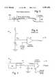
- FIG. 2illustrates a software-based select and test circuit in accordance with the principles of the present invention
- FIG. 3illustrates a conventional RF select and test circuit
- FIG. 4illustrates an RF select and test circuit in accordance with the principles of the present invention
- FIG. 5is a graph illustrating the RF response versus frequency of a traveling wave tube amplifier
- FIG. 6illustrates a conventional traveling wave tube amplifier anode control circuit
- FIG. 7illustrates a traveling wave tube amplifier anode control circuit in accordance with the principles of the present invention.
- FIG. 1illustrates a conventional hardware select and test circuit 10.
- the hardware select and test circuit 10includes a resistor 11 and Zener diode 12 serially coupled between a voltage source and ground.
- Two serially coupled variable resistors 13a, 13bare coupled from a point between the resistor 11 and Zener diode 12 and ground.
- An operational amplifier 14is coupled to a point between the variable resistors 13a, 13b. The output of the operational amplifier 14 provides an adjusted operating point resulting from manually adjusting the variable resistors 13a, 13b.
- Electronic units disposed on a spacecraftrequire select and test alignment to establish the appropriate gain, temperature compensation and bias that provides for optimum performance of the electronic units.
- the electronic unitsinclude but are not limited to receivers, upconverters, downconverters, low noise amplifiers, linearizers, solid state power amplifiers, traveling wave tube (TWT) amplifiers (TWTA) in the payload and the amplifiers, comparitors, motor drivers, heater drivers, etc. in the bus equipment.
- TWTtraveling wave tube
- TWTAtraveling wave tube amplifiers
- a typical select and test operationinvolves at least one and generally two select and test devices (the variable resistors 13a, 13b).
- Analog circuitsare generally modified for operation using an adjustable voltage.
- a serial interface adapter (SIA) 21developed by the assignee of the present invention provides the capability to economically perform select and test functions in software.
- the serial interface adapter 21has ten precision-controlled pulse width modulators (PWM) 22 that can vary their output in 1/1024 increments.
- the serial interface adapter 21also includes a precision voltage reference 23 (Zener diode).
- the output of the serial interface adapter 21is provided by a digital to analog converter (D/A) 28, when filtered using filter 24, such as is provided by a resistor 25 and capacitor 26, for example, provides for a precision software-controlled output voltage which is applied to an operational amplifier 27.
- the output of the operational amplifier 27is an adjusted operating point for a selected electronic unit.
- the select and test values for the electronic unitare automatically established by automatic test equipment coupled to the serial interface adapter 21 that varies the values for optimum performance. This totally eliminates the need for manual soldering or manual adjusting of components in the electronic unit to provide for select and test functions.
- FIG. 3it illustrates a conventional RF select and test circuit 30.
- the conventional RF select and test operationincludes making RF measurements and changing manually adjusted attenuators 32 to obtain the optimum performance and to prevent excessive power from destroying an electronic unit.
- a basic implementationis shown in FIG. 3, where the outputs of two receivers 31 are balanced using RF attenuators 32 coupled to outputs of the respective receivers 31.
- the receivers 31are adjusted to have the same gain so that the electronic unit operates the same when either one of the receivers 31 is used.
- FIG. 4illustrates an RF select and test circuit 40 in accordance with the present invention.
- the RF select and testis performed by software when an attenuator 32a is incorporated n the RF unit.
- An RF computer-controlled attenuator 32ais employed in channel amplifiers used in the present invention.
- the serial interface adapter 21performs the gain adjustment function by way of a serial bus that was previously performed by manually replacing alternative coaxial attenuators.
- the addition of the computer-controllable attenuators 32a in the receiver 31aallows the entire system to be optimized, thus improving performance over the previous operation. It is also extremely fast and does not require the RF path to be broken in order to establish to optimum performance during assembly integration and test alignment.
- Almost all of the payload power for a typical communication satellite or spacecraft 16is established by the DC power supplied to traveling wave tube amplifiers used in the payload.
- the traveling wave tube amplifiersare designed to provide a minimum value of output power over a predetermined frequency range.
- Electronic unitsalso have lower insertion loss than the specified value so that the satellite or spacecraft 16 typically has a higher power output than is required, and which is on the order of at least 0.1 dB total.
- FIG. 5shows a typical graph of output power versus frequency for a traveling wave tube amplifier employed in a communications link.
- the output poweris typically 0.4 dB higher than is required in the center of the band. If it is assumed that the average is 0.2 dB higher over the band, 4.5 percent extra power may be gained by lowering the power output of the traveling wave tube amplifier to the specification level at the frequency of operation. This value increases to 5 percent if the electronic units are on average better than specification. The savings derived from this change is about 3 million dollars for a typically high power communications satellite.
- the powercan be lowered if the requirement is to meet the specification using the redundant electronic unit. This typically requires a higher power in the primary path to assure adequate power in the redundant path which has higher losses due to extra switches and waveguide or coaxial feeds, for example. On the other hand, there are times when the losses are greater than anticipated and the spacecraft 16 does not meet the specification by a small amount. This requires changing the electronic unit or generating paperwork to justify the delivery of an electronic unit with less than specified performance. This problem may be resolved by this computer controlled anode control.
- the traveling wave tube amplifierincorporates an anode regulator.
- the RF power output of the traveling wave tube amplifieris mathematically proportional to beam current.
- the anode regulatorsenses the beam current to maintain a constant power output. The output power therefor may be adjusted by changing the beam current.
- FIG. 6shows a block diagram of a conventional anode control circuit 60 of a traveling wave tube amplifier, which is similar to the conventional select and test circuit 10 used to adjust the reference voltage.
- Conventional traveling wave tube amplifier adjustmentshave been primitive, typically allowing only a one level change by incorporating additional transformers. This arrangement produces a large change (typically 3 dB) in output.
- FIG. 7illustrates a software-based traveling wave tube amplifier anode control circuit 70 in accordance with the principles of the present invention.
- the anode control circuit 70comprises a serial interface adapter (SIA) 21 described above with reference to FIG. 2.
- the output of the serial interface adapter 21is filtered using a filter 24, provided by the resistor 25 and capacitor 26, for example, produces a precision software-controlled output voltage that is applied to the operational amplifier 27.
- the output of the operational amplifier 27is an adjusted operating point for a selected electronic unit.
- the output of the filter circuit 24provides a bias voltage (V ref bias) that is also employed in the anode control circuit 70 that augments the reference voltage (V ref ), thus allowing the RF power output to be changed. Selection and control of the operating point (i.e., the RF power output) is performed at a ground station by way of the serial interface adapter 21.
- V ref biasbias voltage
Landscapes
- Engineering & Computer Science (AREA)
- Software Systems (AREA)
- Artificial Intelligence (AREA)
- Computer Vision & Pattern Recognition (AREA)
- Evolutionary Computation (AREA)
- Medical Informatics (AREA)
- Health & Medical Sciences (AREA)
- Physics & Mathematics (AREA)
- General Physics & Mathematics (AREA)
- Automation & Control Theory (AREA)
- Microwave Amplifiers (AREA)
- Amplifiers (AREA)
- Radio Relay Systems (AREA)
Abstract
Description
Claims (3)
Priority Applications (3)
| Application Number | Priority Date | Filing Date | Title |
|---|---|---|---|
| US08/891,491US5781456A (en) | 1997-07-11 | 1997-07-11 | Software select and test |
| US09/099,154US6018703A (en) | 1997-07-11 | 1998-06-18 | Software select and test |
| DE19830086ADE19830086A1 (en) | 1997-07-11 | 1998-07-06 | Software-controlled selection and test system |
Applications Claiming Priority (1)
| Application Number | Priority Date | Filing Date | Title |
|---|---|---|---|
| US08/891,491US5781456A (en) | 1997-07-11 | 1997-07-11 | Software select and test |
Related Child Applications (1)
| Application Number | Title | Priority Date | Filing Date |
|---|---|---|---|
| US09/099,154DivisionUS6018703A (en) | 1997-07-11 | 1998-06-18 | Software select and test |
Publications (1)
| Publication Number | Publication Date |
|---|---|
| US5781456Atrue US5781456A (en) | 1998-07-14 |
Family
ID=25398282
Family Applications (2)
| Application Number | Title | Priority Date | Filing Date |
|---|---|---|---|
| US08/891,491Expired - LifetimeUS5781456A (en) | 1997-07-11 | 1997-07-11 | Software select and test |
| US09/099,154Expired - Fee RelatedUS6018703A (en) | 1997-07-11 | 1998-06-18 | Software select and test |
Family Applications After (1)
| Application Number | Title | Priority Date | Filing Date |
|---|---|---|---|
| US09/099,154Expired - Fee RelatedUS6018703A (en) | 1997-07-11 | 1998-06-18 | Software select and test |
Country Status (2)
| Country | Link |
|---|---|
| US (2) | US5781456A (en) |
| DE (1) | DE19830086A1 (en) |
Cited By (6)
| Publication number | Priority date | Publication date | Assignee | Title |
|---|---|---|---|---|
| US6018703A (en)* | 1997-07-11 | 2000-01-25 | Space Systems/Loral, Inc. | Software select and test |
| US6298289B1 (en)* | 1999-04-24 | 2001-10-02 | The Boeing Company | Integrated spacecraft control system and method |
| US20080297201A1 (en)* | 2007-06-04 | 2008-12-04 | Quanta Computer Inc. | Complex switch control system |
| CN100454759C (en)* | 2003-11-05 | 2009-01-21 | 华为技术有限公司 | Wave filtering method and apparatus |
| WO2017067034A1 (en)* | 2015-10-20 | 2017-04-27 | 南京航空航天大学 | Microminiature impact monitoring system with ultra-low power consumption based on diode array digitization |
| CN116820073A (en)* | 2023-08-30 | 2023-09-29 | 北京国电高科科技有限公司 | Test system, method, electronic device and storage medium |
Families Citing this family (7)
| Publication number | Priority date | Publication date | Assignee | Title |
|---|---|---|---|---|
| DE10022659A1 (en)* | 2000-04-28 | 2001-10-31 | Deutsche Telekom Ag | Transmission and reception signal measurement involves comparing measured parameters of carrier signals with set values stored in database to detect deviations within predetermined time |
| KR20020032845A (en)* | 2000-10-27 | 2002-05-04 | 장근호 | Method realization for compatibility test between satellite and mission and control element |
| US6561948B2 (en)* | 2000-12-13 | 2003-05-13 | Eaton Corporation | Control for transmission system utilizing centrifugal clutch |
| SG11201606219XA (en)* | 2014-01-28 | 2016-09-29 | Guang Dong Oppo Mobile Telecomm Corp Ltd | Terminal, power adapter and method for handling charging anomaly |
| SG11201606222UA (en) | 2014-01-28 | 2016-08-30 | Guang Dong Oppo Mobile Telecomm Corp Ltd | Power adapter, terminal, and method for processing impedance exception of charging loop |
| DK3101770T3 (en)* | 2014-01-28 | 2019-07-22 | Guangdong Oppo Mobile Telecommunications Corp Ltd | POWER ADAPTERS AND TERMINAL |
| CN109460002B (en)* | 2018-09-27 | 2020-09-04 | 电子科技大学 | High-efficiency control protection system and method in high-power millimeter wave test process |
Citations (9)
| Publication number | Priority date | Publication date | Assignee | Title |
|---|---|---|---|---|
| US4435679A (en)* | 1981-05-26 | 1984-03-06 | General Electric Company | Programmable signal amplitude control circuits |
| US4494212A (en)* | 1982-03-03 | 1985-01-15 | The Perkin-Elmer Corporation | Variable gain amplifier |
| US4510454A (en)* | 1983-11-14 | 1985-04-09 | John Fluke Mfg. Co., Inc. | Apparatus for digitally controlled calibration of frequency response of amplifiers |
| US4541065A (en)* | 1982-09-14 | 1985-09-10 | John Fluke Mfg. Co., Inc. | Direct volts calibrator |
| US4868519A (en)* | 1988-11-02 | 1989-09-19 | Dnic Brokerage Company | Microprocessor-controlled amplifier |
| US5010306A (en)* | 1990-02-20 | 1991-04-23 | At&T Bell Laboratories | Low cost digital amplitude regulator |
| US5027083A (en)* | 1990-02-20 | 1991-06-25 | At&T Bell Laboratories | General purpose low cost digital amplitude regulator |
| US5121076A (en)* | 1991-05-06 | 1992-06-09 | Thomson Consumer Electronics, Inc. | Plural time constant signal control |
| US5625316A (en)* | 1994-07-01 | 1997-04-29 | Motorola, Inc. | Tuning circuit for an RC filter |
Family Cites Families (1)
| Publication number | Priority date | Publication date | Assignee | Title |
|---|---|---|---|---|
| US5781456A (en)* | 1997-07-11 | 1998-07-14 | Space Systems/Loral, Inc. | Software select and test |
- 1997
- 1997-07-11USUS08/891,491patent/US5781456A/ennot_activeExpired - Lifetime
- 1998
- 1998-06-18USUS09/099,154patent/US6018703A/ennot_activeExpired - Fee Related
- 1998-07-06DEDE19830086Apatent/DE19830086A1/ennot_activeWithdrawn
Patent Citations (9)
| Publication number | Priority date | Publication date | Assignee | Title |
|---|---|---|---|---|
| US4435679A (en)* | 1981-05-26 | 1984-03-06 | General Electric Company | Programmable signal amplitude control circuits |
| US4494212A (en)* | 1982-03-03 | 1985-01-15 | The Perkin-Elmer Corporation | Variable gain amplifier |
| US4541065A (en)* | 1982-09-14 | 1985-09-10 | John Fluke Mfg. Co., Inc. | Direct volts calibrator |
| US4510454A (en)* | 1983-11-14 | 1985-04-09 | John Fluke Mfg. Co., Inc. | Apparatus for digitally controlled calibration of frequency response of amplifiers |
| US4868519A (en)* | 1988-11-02 | 1989-09-19 | Dnic Brokerage Company | Microprocessor-controlled amplifier |
| US5010306A (en)* | 1990-02-20 | 1991-04-23 | At&T Bell Laboratories | Low cost digital amplitude regulator |
| US5027083A (en)* | 1990-02-20 | 1991-06-25 | At&T Bell Laboratories | General purpose low cost digital amplitude regulator |
| US5121076A (en)* | 1991-05-06 | 1992-06-09 | Thomson Consumer Electronics, Inc. | Plural time constant signal control |
| US5625316A (en)* | 1994-07-01 | 1997-04-29 | Motorola, Inc. | Tuning circuit for an RC filter |
Cited By (9)
| Publication number | Priority date | Publication date | Assignee | Title |
|---|---|---|---|---|
| US6018703A (en)* | 1997-07-11 | 2000-01-25 | Space Systems/Loral, Inc. | Software select and test |
| US6298289B1 (en)* | 1999-04-24 | 2001-10-02 | The Boeing Company | Integrated spacecraft control system and method |
| CN100454759C (en)* | 2003-11-05 | 2009-01-21 | 华为技术有限公司 | Wave filtering method and apparatus |
| US20080297201A1 (en)* | 2007-06-04 | 2008-12-04 | Quanta Computer Inc. | Complex switch control system |
| US8125354B2 (en)* | 2007-06-04 | 2012-02-28 | Quanta Computer Inc. | Complex switch control system |
| WO2017067034A1 (en)* | 2015-10-20 | 2017-04-27 | 南京航空航天大学 | Microminiature impact monitoring system with ultra-low power consumption based on diode array digitization |
| US10145746B2 (en) | 2015-10-20 | 2018-12-04 | Nanjing University Of Aeronautics And Astronautics | Diode array-based digitized miniature ultra-low-power-consumption impact monitoring system |
| CN116820073A (en)* | 2023-08-30 | 2023-09-29 | 北京国电高科科技有限公司 | Test system, method, electronic device and storage medium |
| CN116820073B (en)* | 2023-08-30 | 2023-11-14 | 北京国电高科科技有限公司 | Test system, method, electronic device and storage medium |
Also Published As
| Publication number | Publication date |
|---|---|
| US6018703A (en) | 2000-01-25 |
| DE19830086A1 (en) | 1999-01-14 |
Similar Documents
| Publication | Publication Date | Title |
|---|---|---|
| US5781456A (en) | Software select and test | |
| EP0138901B1 (en) | Stabilized microwave power amplifier system | |
| US5500621A (en) | Travelling-wave tube protection arrangement | |
| EP0330774B1 (en) | Reduction of undesired harmonic components | |
| EP1428313B1 (en) | A system and method for minimizing dissipation in rf power amplifiers | |
| US6756844B2 (en) | Distortion compensation amplification apparatus of feed forward type and adaptive pre-distortion type | |
| EP0788223B1 (en) | Pin diode variable attenuator | |
| US4882547A (en) | Linearizer control system | |
| EP1478088B1 (en) | Variable high power amplifier with constant overall gain for a satellite communication system | |
| US6919774B2 (en) | Broadband PIN diode attenuator bias network | |
| EP1098435A1 (en) | Low cost miniature broadband linearizer | |
| US5296821A (en) | Method and apparatus for controlling transient responses in a power amplifier | |
| CA2483251C (en) | Multi-beam communication satellite antenna with failure compensation | |
| US6973288B1 (en) | Linearizer for a PIN diode attenuator | |
| US6057733A (en) | Feedforward multicarrier linear RF power amplifier | |
| CN118041298A (en) | Novel low-phase-shift radio frequency attenuator circuit, additional phase error eliminating circuit and system | |
| US7068423B2 (en) | Low cost flexible automated optical power management | |
| US7138863B2 (en) | Gain control of a power amplifier | |
| US6242976B1 (en) | Low cost linearized channel amplifier for use with high power amplifiers | |
| KR100407939B1 (en) | Apparatus for auto gain controller in mobile communication system's BTS | |
| US4412189A (en) | Switchable signal compressor/signal expander | |
| CN112821874B (en) | Compression point adjusting method and device and power amplifier power supply circuit | |
| EP3242413A1 (en) | Power system for a satellite | |
| Huebner et al. | A new approach for a microwave power module (MPM) | |
| Andre et al. | Flexible TWT amplifier for space applications |
Legal Events
| Date | Code | Title | Description |
|---|---|---|---|
| AS | Assignment | Owner name:SPACE SYSTEMS/LORAL, INC., CALIFORNIA Free format text:ASSIGNMENT OF ASSIGNORS INTEREST;ASSIGNOR:DODD, ROBERT W.;REEL/FRAME:008690/0189 Effective date:19970709 | |
| FEPP | Fee payment procedure | Free format text:PAYOR NUMBER ASSIGNED (ORIGINAL EVENT CODE: ASPN); ENTITY STATUS OF PATENT OWNER: LARGE ENTITY | |
| STCF | Information on status: patent grant | Free format text:PATENTED CASE | |
| FPAY | Fee payment | Year of fee payment:4 | |
| REMI | Maintenance fee reminder mailed | ||
| FPAY | Fee payment | Year of fee payment:8 | |
| AS | Assignment | Owner name:JPMORGAN CHASE BANK, N.A., AS ADMINISTRATIVE AGENT Free format text:SECURITY AGREEMENT;ASSIGNOR:SPACE SYSTEMS/LORAL, INC.;REEL/FRAME:021965/0173 Effective date:20081016 | |
| FPAY | Fee payment | Year of fee payment:12 | |
| AS | Assignment | Owner name:SPACE SYSTEMS/LORAL, INC., CALIFORNIA Free format text:TERMINATION AND RELEASE OF SECURITY INTEREST IN PATENT RIGHTS;ASSIGNOR:JPMORGAN CHASE BANK, N.A.;REEL/FRAME:029228/0203 Effective date:20121102 | |
| AS | Assignment | Owner name:SPACE SYSTEMS/LORAL, LLC, CALIFORNIA Free format text:CHANGE OF NAME;ASSIGNOR:SPACE SYSTEMS/LORAL, INC.;REEL/FRAME:030291/0536 Effective date:20121102 | |
| AS | Assignment | Owner name:ROYAL BANK OF CANADA, CANADA Free format text:SECURITY AGREEMENT;ASSIGNOR:SPACE SYSTEMS/LORAL, LLC;REEL/FRAME:030311/0961 Effective date:20121102 | |
| AS | Assignment | Owner name:ROYAL BANK OF CANADA, AS THE COLLATERAL AGENT, CANADA Free format text:SECURITY INTEREST;ASSIGNORS:DIGITALGLOBE, INC.;MACDONALD, DETTWILER AND ASSOCIATES LTD.;MACDONALD, DETTWILER AND ASSOCIATES CORPORATION;AND OTHERS;REEL/FRAME:044167/0396 Effective date:20171005 Owner name:ROYAL BANK OF CANADA, AS THE COLLATERAL AGENT, CAN Free format text:SECURITY INTEREST;ASSIGNORS:DIGITALGLOBE, INC.;MACDONALD, DETTWILER AND ASSOCIATES LTD.;MACDONALD, DETTWILER AND ASSOCIATES CORPORATION;AND OTHERS;REEL/FRAME:044167/0396 Effective date:20171005 | |
| AS | Assignment | Owner name:MAXAR SPACE LLC, CALIFORNIA Free format text:TERMINATION AND RELEASE OF SECURITY INTEREST IN PATENTS AND TRADEMARKS - RELEASE OF REEL/FRAME 044167/0396;ASSIGNOR:ROYAL BANK OF CANADA, AS AGENT;REEL/FRAME:063543/0001 Effective date:20230503 Owner name:MAXAR INTELLIGENCE INC., COLORADO Free format text:TERMINATION AND RELEASE OF SECURITY INTEREST IN PATENTS AND TRADEMARKS - RELEASE OF REEL/FRAME 044167/0396;ASSIGNOR:ROYAL BANK OF CANADA, AS AGENT;REEL/FRAME:063543/0001 Effective date:20230503 |