US5781344A - Light transmitting and dispersing filter having low reflectance - Google Patents
Light transmitting and dispersing filter having low reflectanceDownload PDFInfo
- Publication number
- US5781344A US5781344AUS08/729,803US72980396AUS5781344AUS 5781344 AUS5781344 AUS 5781344AUS 72980396 AUS72980396 AUS 72980396AUS 5781344 AUS5781344 AUS 5781344A
- Authority
- US
- United States
- Prior art keywords
- light
- beads
- layer
- light absorbing
- absorbing layer
- Prior art date
- Legal status (The legal status is an assumption and is not a legal conclusion. Google has not performed a legal analysis and makes no representation as to the accuracy of the status listed.)
- Expired - Fee Related
Links
- 230000003287optical effectEffects0.000claimsabstractdescription35
- 239000010410layerSubstances0.000claimsdescription213
- 239000011324beadSubstances0.000claimsdescription187
- 239000000463materialSubstances0.000claimsdescription156
- 239000011358absorbing materialSubstances0.000claimsdescription18
- 239000002356single layerSubstances0.000claimsdescription13
- 238000000034methodMethods0.000claimsdescription9
- 238000012856packingMethods0.000claimsdescription7
- 238000000576coating methodMethods0.000claimsdescription4
- 239000004033plasticSubstances0.000claimsdescription4
- 239000011149active materialSubstances0.000claimsdescription3
- 239000003795chemical substances by applicationSubstances0.000claimsdescription3
- 230000005684electric fieldEffects0.000claimsdescription3
- 239000011248coating agentSubstances0.000claimsdescription2
- 239000012530fluidSubstances0.000claimsdescription2
- 239000011343solid materialSubstances0.000claimsdescription2
- 238000004519manufacturing processMethods0.000claims9
- 238000000151depositionMethods0.000claims5
- 239000000835fiberSubstances0.000claims2
- 238000007373indentationMethods0.000claims2
- 230000035515penetrationEffects0.000claims2
- 230000000149penetrating effectEffects0.000claims1
- 238000003892spreadingMethods0.000claims1
- 239000012815thermoplastic materialSubstances0.000claims1
- 239000011230binding agentSubstances0.000description61
- 229920005989resinPolymers0.000description44
- 239000011347resinSubstances0.000description44
- 230000005540biological transmissionEffects0.000description26
- 238000010586diagramMethods0.000description10
- 239000011521glassSubstances0.000description9
- 239000000758substrateSubstances0.000description7
- 238000009826distributionMethods0.000description4
- 239000012508resin beadSubstances0.000description4
- 238000010521absorption reactionMethods0.000description3
- 230000007423decreaseEffects0.000description3
- 239000000203mixtureSubstances0.000description3
- SOGAXMICEFXMKE-UHFFFAOYSA-NButylmethacrylateChemical compoundCCCCOC(=O)C(C)=CSOGAXMICEFXMKE-UHFFFAOYSA-N0.000description2
- 239000003086colorantSubstances0.000description2
- 230000000694effectsEffects0.000description2
- 239000007789gasSubstances0.000description2
- 239000007788liquidSubstances0.000description2
- 239000002184metalSubstances0.000description2
- 238000005457optimizationMethods0.000description2
- 238000005507sprayingMethods0.000description2
- 229920001169thermoplasticPolymers0.000description2
- 229920005992thermoplastic resinPolymers0.000description2
- 239000004416thermosoftening plasticSubstances0.000description2
- 238000011282treatmentMethods0.000description2
- 230000002411adverseEffects0.000description1
- 238000013459approachMethods0.000description1
- 230000003190augmentative effectEffects0.000description1
- 239000006229carbon blackSubstances0.000description1
- 230000003467diminishing effectEffects0.000description1
- 238000001962electrophoresisMethods0.000description1
- 230000008030eliminationEffects0.000description1
- 238000003379elimination reactionMethods0.000description1
- 230000005294ferromagnetic effectEffects0.000description1
- 230000005291magnetic effectEffects0.000description1
- 239000011159matrix materialSubstances0.000description1
- 230000000704physical effectEffects0.000description1
- 239000000049pigmentSubstances0.000description1
- 239000002985plastic filmSubstances0.000description1
- 229920006255plastic filmPolymers0.000description1
- 229920000642polymerPolymers0.000description1
- 230000005855radiationEffects0.000description1
- 238000002310reflectometryMethods0.000description1
- 238000005096rolling processMethods0.000description1
- 239000002904solventSubstances0.000description1
- 238000006467substitution reactionMethods0.000description1
- 238000005406washingMethods0.000description1
Images


Classifications
- G—PHYSICS
- G02—OPTICS
- G02B—OPTICAL ELEMENTS, SYSTEMS OR APPARATUS
- G02B5/00—Optical elements other than lenses
- G02B5/02—Diffusing elements; Afocal elements
- G02B5/0205—Diffusing elements; Afocal elements characterised by the diffusing properties
- G02B5/021—Diffusing elements; Afocal elements characterised by the diffusing properties the diffusion taking place at the element's surface, e.g. by means of surface roughening or microprismatic structures
- G02B5/0215—Diffusing elements; Afocal elements characterised by the diffusing properties the diffusion taking place at the element's surface, e.g. by means of surface roughening or microprismatic structures the surface having a regular structure
- C—CHEMISTRY; METALLURGY
- C03—GLASS; MINERAL OR SLAG WOOL
- C03C—CHEMICAL COMPOSITION OF GLASSES, GLAZES OR VITREOUS ENAMELS; SURFACE TREATMENT OF GLASS; SURFACE TREATMENT OF FIBRES OR FILAMENTS MADE FROM GLASS, MINERALS OR SLAGS; JOINING GLASS TO GLASS OR OTHER MATERIALS
- C03C12/00—Powdered glass; Bead compositions
- G—PHYSICS
- G02—OPTICS
- G02B—OPTICAL ELEMENTS, SYSTEMS OR APPARATUS
- G02B5/00—Optical elements other than lenses
- G02B5/02—Diffusing elements; Afocal elements
- G02B5/0205—Diffusing elements; Afocal elements characterised by the diffusing properties
- G02B5/0257—Diffusing elements; Afocal elements characterised by the diffusing properties creating an anisotropic diffusion characteristic, i.e. distributing output differently in two perpendicular axes
- G—PHYSICS
- G02—OPTICS
- G02B—OPTICAL ELEMENTS, SYSTEMS OR APPARATUS
- G02B5/00—Optical elements other than lenses
- G02B5/02—Diffusing elements; Afocal elements
- G02B5/0273—Diffusing elements; Afocal elements characterized by the use
- G02B5/0278—Diffusing elements; Afocal elements characterized by the use used in transmission
- G—PHYSICS
- G02—OPTICS
- G02B—OPTICAL ELEMENTS, SYSTEMS OR APPARATUS
- G02B5/00—Optical elements other than lenses
- G02B5/20—Filters
- G02B5/206—Filters comprising particles embedded in a solid matrix
- G—PHYSICS
- G03—PHOTOGRAPHY; CINEMATOGRAPHY; ANALOGOUS TECHNIQUES USING WAVES OTHER THAN OPTICAL WAVES; ELECTROGRAPHY; HOLOGRAPHY
- G03B—APPARATUS OR ARRANGEMENTS FOR TAKING PHOTOGRAPHS OR FOR PROJECTING OR VIEWING THEM; APPARATUS OR ARRANGEMENTS EMPLOYING ANALOGOUS TECHNIQUES USING WAVES OTHER THAN OPTICAL WAVES; ACCESSORIES THEREFOR
- G03B21/00—Projectors or projection-type viewers; Accessories therefor
- G03B21/54—Accessories
- G03B21/56—Projection screens
- G03B21/60—Projection screens characterised by the nature of the surface
- G03B21/62—Translucent screens
- G03B21/625—Lenticular translucent screens
Definitions
- This inventionrelates to the field of light filters, and in particular to light filters for rear projection screens, display enhancement, and other optical uses requiring dispersive light control.
- Rear projection screens and light diffusersare light filters which provide an optically diffusing medium for transmitting light from an image source on one side of the screen to a viewer on the opposite side of the screen.
- a basic refractive light filterhas been described in U.S. Pat. No. 2,378,252, which includes a refracting lens system as its principal component.
- the refracting lens systemcomprises an array of spherical glass or resin beads embedded in an opaque binder layer and mounted on a transparent support material.
- the light filteris oriented with the bead layer towards the image source and the transparent support material towards the viewers.
- U.S. Pat. No. 3,552,822discloses a similar light filter which also includes an anti-reflection coating and has its bead layer oriented away from the image source.
- the opaque binder layerserves a number of purposes, including affixing beads to the support material, reducing the reflectivity of the filter, and reducing the amount of light transmitted through the interstices between the beads of the lens system.
- Light from an imageis refracted by the beads and dispersed to the viewer through a transmission area of the beads.
- This transmission areacomprises the point of contact between the bead and support material and the area surrounding this point where the binder layer is too thin to absorb the refracted light.
- Rear projection screens and light diffusersare characterized by their ambient light rejection, resolution, gain, and contrast, properties which are determined by the structure and composition of the component materials.
- the gainwhich is a measure of the intensity of transmitted light as a function of the viewing angle, is determined by the index of refraction of the spherical beads and the surrounding medium.
- the ambient light rejection and contrast of the light filterare determined largely by the opacity of the binder layer.
- the resolution of the screenis determined by the size of the beads used in the lens system.
- the present inventionis a multi-layer light filter that provides high image transmission, high ambient light rejection, high contrast, and improved gain control.
- Multi-layer light filters in accordance with the present inventioninclude glass or resin beads supported in an opaque layer and modified by additional optical layers. These layers provide means to vary the optical properties of the filter, and consequently allow improved image transmission, ambient light rejection, and gain control.
- the gain control provided by the index of refraction of the beadsis augmented by the addition of a transparent resin layer to the rear surface of the beads.
- the transparent resin layerprovides additional gain control by replacing the air/bead interface with air/resin and resin/bead interfaces at which the refraction of image light can be separately adjusted.
- Refraction at the resin/bead interfaceis controlled by selecting the relative indices of refraction of the transparent resin layer and the beads.
- Refraction at the air/resin interfacemay be adjusted by selecting the thickness of the transparent resin layer in addition to its index of refraction, a thin layer of transparent resin being effective to alter the shape of the rear surface of the beads.
- Light reflection and absorption propertiesare improved by the addition of an opaque resin layer to the back of the opaque binder layer, which allows the interstitial transmission of the multi-layer filter to be controlled without altering the opacity of the binder layer.
- an opaque resin layerto the back of the opaque binder layer, which allows the interstitial transmission of the multi-layer filter to be controlled without altering the opacity of the binder layer.
- the ambient light rejection, contrast, and control of interstitial transmission of the filterare enhanced without diminishing its image light transmission.
- the optical properties of multi-layer light filters in accordance with the present inventioncan be simultaneously improved.
- Multi-layer light filters in accordance with the present inventionmay be used for example as rear projection screens or as contact light diffusers.
- near-collimated lightis incident on the light filter from an image light source which is well separated from the multi-layer filter.
- the multi-layer filteris positioned on an image source such as a flat panel display, which is illuminated from behind with collimated light.
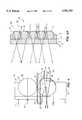
- FIGS. 1A, 1B, 1Care schematic diagrams of a basic refractive rear projection screen, including cross sections taken at two different locations;
- FIG. 2is a diagram indicating the refraction of light rays by spherical beads in a basic refractive light filter
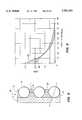
- FIG. 3is a graph of the gain profiles for three light filters having different indices of refraction in the glass beads
- FIG. 4is a schematic diagram of ambient light rays refracted and retro-reflected by the rear surface of beads
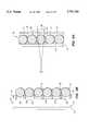
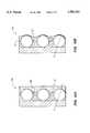
- FIGS. 5A, 5Bare schematic diagrams of light filters in accordance with the present invention in which the interstices between beads at the rear of the filters have been partially filled with transparent resin to control their gain.
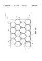
- FIG. 5Cis a schematic diagram of a light filter in accordance with the present invention in which the interstices between larger beads of the light filter include a plurality of smaller beads for increasing the packing density of beads in the light filter;
- FIGS. 6A, 6Bare schematic diagrams of light filters in accordance with the present invention in which a transparent resin layer having an index of refraction different from that of the spherical lenses has been added to the rear surfaces of the beads to control their gain;
- FIG. 7is a graph of the gain profile versus angle from the normal to the viewing surface for a basic refractive light filter and for a light filter having an additional resin layer in accordance with the present invention
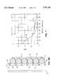
- FIG. 8is a cross section of a light filter in accordance with the present invention in which a second opaque layer has been added to the filter to enhance its ambient light rejection and image contrast;
- FIG. 9is a gain profile for a basic refractive light filter and for a multi-layer light filter including a second opaque layer;
- FIG. 10Ais a schematic diagram of a light filter in accordance with the present invention in which a second opaque layer and a transparent resin layer have been added to the filter to enhance its gain control, ambient light rejection, and image contrast;
- FIG. 10Bis a schematic diagram of a light filter in accordance with the present invention in which a second opaque layer and a thin transparent resin layer have been added to the filter to enhance its gain control, ambient light rejection, and image contrast.
- FIG. 1Athere is shown diagram of a conventional, basic refractive light filter 10.
- FIGS. 1B and 1Cthere are shown cross sections of light filter 10 at the locations indicated in FIG. 1A.
- Basic refractive light filter 10includes a transparent support material 12 which has a filter surface 18 and a support surface 13. Spherical glass or resin beads 14 are partially embedded in an opaque binder layer 16, which binds beads 14 to support surface 13.
- Filter surface 18defines a front side of light filter 10 through which viewers observer transmitted image light.
- light incident on beads 14is refracted, transmitted through binder layer 16 at a transmission area 34, and dispersed to viewers through filter surface 18.
- Light incident on back surface 19 of binder layer 16may reach viewers through interstices 20 between beads 14.
- One role of opaque binder layer 16is to reduce transmission of this light.
- FIG. 2there is shown a diagram of the paths followed by refracted light rays 22, 24, 26, 28 incident on back surface 36 of bead 14 at various distances from optic axis 30.
- Light rays 22-28are refracted towards optic axis 30 by an angle ⁇ that increases with the distance between point of incidence 31 and optic axis 30.
- Angle ⁇also increases with the index of refraction of beads 14.
- Refracted light rays 22, 24, 26, 28are directed through transmission area 34, which includes the point of contact between bead 14 and support surface 13 as well as the surrounding area where intervening opaque binder layer 16 is too thin to absorb refracted light rays 22, 24, 26, 28.
- refracted ray 29which strikes the front surface of bead 14 outside of transmission area 34 is absorbed as it transits opaque binder. layer 16.
- Refracted rays 22, 24, 26, 28diverge after passing through transmission area 34 of bead 14, dispersing transmitted light intensity over a range of angles ⁇ .
- the collective action of beads 14disperses transmitted light intensity at various angles relative to a normal 11 of filter surface 18, and this intensity distribution is referred to as the gain profile.
- High gain light filters 10transmit image light in a narrow angular distribution about normal 11, whereas low gain filters 10 transmit image light in broad distributions about normal 11.
- the optimum gain for light filter 10will depend on its intended use, and is selected in part by choosing component beads 14 having an appropriate index of refraction.
- FIG. 3there are plotted gain profiles 40, 42, 44 for basic refractive light filters 10 comprising beads 14 having indices of refraction of 1.5, 1.7, and 1.9, respectively.
- the gain at 0° with respect to normal 11is greatest for low index, beads 14 and decreases with increasing index of refraction.
- the greater refractive power of high index beads 14refracts transmitted rays 22, 24, 26, 28 more sharply than low index materials, and they subsequently diverge over a wider range of angles from normal 11 and are less focused along normal 11.
- light filters 10are characterized by their resolution, contrast, and ambient light rejection. It is generally desirable that filters 10 have both high resolution and high ambient light rejection.
- the resolution of light filters 10is determined by the size of beads 14, since the packing density of beads 14 on support surface 13 determines the density of transmission areas 34 on this surface. This property can generally be maximized by constructing filters 10 using the smallest diameter beads 14 available.
- the size of beads 14 selectedmay be dictated by variations in the quality and properties of available beads 14.
- Ambient light rejectionmeasures how well ambient light incident on the front of a light filter 10 is absorbed or transmitted relative to the amount re-dispersed back to the viewer. This property depends primarily on the opacity of binder layer 16 and the index of refraction of beads 14. Ambient light reflected into viewers' eyes from filter 10 can significantly impair the quality of an image by washing out the contrast.
- ambient light incident on filter surface 18may be reflected at the interfaces between: opaque binder layer 16 and support surface 13, beads 14 and opaque binder layer 16, and beads 14 and air at back surface 36.
- opaque binder layer 16 and support surface 13may be reflected at the interfaces between: opaque binder layer 16 and support surface 13, beads 14 and opaque binder layer 16, and beads 14 and air at back surface 36.
- the lastis typically most important since the indices of refraction of support material 12, opaque binder layer 16, and beads 14 can be made approximately equal, minimizing reflection from the first two interfaces.
- Specular, non-dispersive reflection from filter surface 18is also present in all filters 10, and is typically minimized by means of anti-reflection and anti-glare coatings and treatments. While these coatings and treatments are not within the scope of the present invention, they may be applied concurrently to enhance the overall performance of the present invention.
- FIG. 4there are shown ambient light rays 23 passing through support material 12 and incident on rear surface 36 of a spherical bead 14 having an index of refraction of 1.5.
- Ris the radius of bead 14.
- Retro-reflected rays 23which are not absorbed by opaque binder layer 16 exit filter 10 along with transmitted image light 22, 24, 26, 28, and thereby diminish the quality of the image.
- image light transmitted through interstices 20 between beads 14also reduces the quality of an image.
- Light rays 21 following this trajectoryare not refracted by beads 14 and interfere with the gain profile of properly refracted light rays 22, 24, 26, 28.
- the intensity of light rays 21 transmitted through interstices 20 and those retro-reflected from beads 14are controlled by the opacity of binder layer 16.
- Retro-reflected rays 23pass through approximately twice as much binder layer 16 as transmitted rays 21, and are consequently absorbed at lower opacities than transmitted rays 21.
- increasing the opacity of binder layer 16 to reduce transmitted rays 21reduces transmission of image light through transmission area 34 as discussed above.
- compromises between maximizing transmitted light and minimizing retro-reflected and interstitially transmitted lightlimit optimization of basic refractive filters 10.
- the degree of gain control in basic refractive light filters 10is also constrained. For instance, reducing the index of refraction of beads 14 to create higher gain at 0° necessarily reduces the refracting power of beads 14. As a result, the amount of light focused into transmission area 34 and subsequently transmitted to filter surface 18 is reduced, reducing the intensity of transmitted image light.
- the degree of gain control available through varying the index of refraction of beads 14may also be limited by the physical properties of existing materials. Flattening beads 14 to increase the radius of curvature of the back surfaces 36 provides an alternative means for increasing the gain of basic refractive light filters 10. However, where this flattening is achieved by simply compressing deformable resin beads 14 parallel to optic axis 30, the distance between individual beads 14 increases, resulting in a lower density of beads 14 and lower resolution.
- the present inventionoptimizes both the gain and ambient light rejection of light filters 10 through the addition of layers of material having selected optical properties and the substitution of new materials for the structures of light filters 10.
- new light filters 50, 70, 80, 90as discussed in conjunction with FIGS. 5, 6, 8 and 10 are produced by adding new layers 62, 72, 82 of optical materials to basic light filter 10, which is constructed with glass or resin support materials 12, binder layers 16, and beads 14 selected to optimize the desired optical properties. Since filters 50, 70, 80, 90 are based on light filter 10, the components of light filter 10 and their combinations are discussed first.
- the optical and mechanical properties of support material 12contribute to the characteristics of filters 50, 70, 80, 90 in a variety of ways.
- the index of refraction of support material 12affects the angular distribution of transmitted light through refraction, and the contrast through its influence on internal reflection.
- absorbing materialscan be included in support materials 12 to reduce back reflectance and lateral internal reflectance.
- use of photochromic glass for support material 12automatically increases the absorption and decreases the reflectance of support material 12 in bright ambient light conditions.
- the use of electrically active optical material for support material 12allows the optical properties to be varied dynamically. These effects can be used in conjunction with the optical properties of beads 14, binder layer 16, and layers 62, 72, 82 to fine tune the performance of filters 50, 70, 80, 90.
- support material 12can also be selected according to the use to which filters 50, 70, 80, 90 are put.
- plastic support materials 12reduce the weight and flexible materials such as plastic films can be used to produce flexible filters 50, 70, 80, 90.
- support material 12can be removed to provide flat or shaped free standing light filters 50, 70, 80, 90.
- Binder layers 16may be made from a variety of matrix materials. For example, butyl methacrylate polymers readily mix with colorants and their thermoplastic properties provide a simple means for embedding beads 14. Generally, UV, thermal, and chemically cured resins may be used to produce binder layer 16. These materials may be applied in several layers 16 each having different optical densities. Alternatively, binder layer 16 may be a photosensitive film, in which case its optical density can be varied with depth by exposure to actinic light. Photochromic materials on the other hand provide a binder layer 16 that automatically adjusts its absorption in response to ambient light conditions. In addition to film and resin type materials, binder layer 16 may be a wire mesh or perforated metal sheet as is discussed in conjunction with FIG. 5B, or a combination of mesh and clear resin materials.
- beads 14may be embedded in a close-packed array using a number of processes.
- support material 12is coated with a thermoplastic resin binder layer 16 which is modified by a colorant to adjust the binder layer 16 to the desired opacity.
- Beads 14are then spread over the thermoplastic resin binder layer 16 which is subsequently heated, allowing beads 14 to be pressed into resin binder layer 16 until they contact support surface 13.
- Beads 14may also be deposited by electrophoresis from a fluid medium, by spraying a mixture of beads 14, material for binder layer 16, and a solvent onto support material 12, or by spraying beads 14 directly onto a softened binder layer 16.
- Close packing of beads 14may be enhanced by applying electrostatic charges to beads 14 and/or binder layer 16 or support material 12 to position beads 14.
- beads 14may be pre-positioned on a surface shaped to enforce close packing, and subsequently transferred to binder layer 16.
- Electrostatic assisted transfer as in xerographymay also be used to transfer and position beads 14 onto binder layer 16.
- Beads 14may be selected from a variety of glass or resin materials, the optimal material and size of beads 14 may depend on the intended application of light filter 50, 70, 80, 90. Transparent glass or resin materials are available with indices of refraction of between about 1.4 and 2.1, and combinations of materials may be used to provide additional gain control. For example, beads 14 formed by encapsulating electro-optically active materials in glass or resin allow for the adjustment of the optical properties of beads 14 by application of an electric field. Beads 14 may also be composed of photochromic material to allow their optical properties to respond to changes in incident light intensity. Alternatively, colored beads 14 may be used to allow chromatic effects.
- Light filters 50, 70, 80, 90can be constructed with beads 14 of any diameter.
- the diameteris selected according to the desired resolution.
- beads 14 of differing diametermay be combined in the same light filter 50, 70, 80, 90.
- smaller diameter beads 14may be added to the interstices 20 of an array of larger diameter beads 14 to increase the packing density as illustrated in light filter 150 of FIG. 5C.
- Beads 14 which can be permanently or temporarily deformedmay also be used to provide an additional gain control mechanism.
- Out-of-round beads 14cause uneven refraction of light, which creates bright spots and graininess in the viewed images in filters 50, 70, 80, 90.
- the inclusion of opaque or frosted beads 14creates dark spots in filters 50, 70, 80, 90 and reduces transmission efficiency.
- Preliminary sorting of beads 14can be done using fine screens or meshes. Discolored beads are often ferromagnetic, and can be separated in a magnetic field. Out-of-round beads 14 can be separated by rolling them down a vibrating plane or allowing them to settle through a vibrating column, relying on the faster passage of round beads.
- beads 14having non-spherical shapes such as ellipsoids or rounded rods. Such non-spherical beads can be deposited in alignments that provide different optical properties in different directions.
- Light filter 50in accordance with the present invention, which provides additional gain control beyond that provided by the index of refraction of component beads 14.
- Light filter 50comprises a transparent support medium 12, having a support surface 13 and a filter surface 18, and an opaque binder layer 16 in which spherical beads 14 having a selected index of refraction are embedded.
- a thin layer 62 of transparent resinis deposited in depressions 64 created by back surfaces 36 of beads 14 protruding from back surface 19 of binder layer 16.
- the index of refraction of resin layer 62may be greater, less than, or substantially equal to that of beads 14, depending on the desired gain of filter 50.
- Resin layer 62increases the effective radius of curvature of back surfaces 36 of beads 14, thus reducing their refractive power.
- refracted rays 28' for untreated beads 14'are shown at the top of FIG. 5A.
- the actual refractive power of beads 14will vary with the degree to which depressions 64 are filled. This dependence provides a means to adjust the gain of light filter 50 in addition to changing the index of refraction of beads 14.
- depressions 64are completely filled with resin layer 62, and as long as resin layer 62 has the same index of refraction as beads 14, light rays incident normal to the resulting plane surface will not be refracted. Where resin layer 62 and beads 14 have different indices of refraction, however, refraction will occur at back surface 36 of beads 14, providing another means for controlling the gain of multi-layer light filter 50 beyond varying the index of refraction of beads 14.
- a light filter 50in which opaque binder layer 16 is an opaque metal or plastic substrate 52 having a grid of perforations 54 in which beads 14 are supported.
- Perforations 54are sized to accommodate beads 14 to a pre-selected depth 56, and the grid of perforations 54 is chosen to provide close packing of beads 14 or alignment of beads 14 in a preferred manner. The latter situation may arise for example where the source of image light is a digital video display, in which case it may be desirable to align beads 14 with the pixels of the video display.
- light filter 50may be assembled with or without support material 12.
- a flexible light filter 50is provided by using a flexible opaque substrate 52 such as a plastic mesh or net, and either omitting support material 12 or using a flexible support material 12.
- a clear or colored resin layermay be combined with opaque substrate 52 to form binder layer 16.
- a resin layer 62may be included to increase the effective radius of curvature of rear surface 36 of beads 14.
- light filters 50, 70, 80, 90 realized using an opaque resin for binder layer 16may also be implemented using opaque substrate 52 or a combination of resin and substrate 52 for the same purpose.
- support surface 13, bead 14, and substrate 52create a cavity 53 which may be filled with liquid or gases having optical properties chosen to alter the characteristics of filter 50.
- Liquid or gas materials in cavities 53extend the range of optical properties beyond what is available in solid materials. These properties can be altered by temperature, pressure, or radiation, adding another parameter to control the optical properties of filter 50.
- Light filter 70having gain control in addition to that provided by the index of refraction of beads 14.
- Light filter 70has an array of beads 14 embedded in an opaque binder layer 16 which is affixed to support material 12.
- a layer of clear resin 72having an index of refraction different from that of beads 14 is added to rear surface 36 of beads 14 and rear surface 19 of binder layer 16.
- resin layer 72is sufficiently thick to fully enclose beads 14 and present a planar surface 74 to incident image light. As indicated, light rays 28 from an image source are incident normally on planar surface 74 where they undergo no refraction.
- Ray 28is drawn for the case where beads 14, binder layer 16, and support material 12 have substantially equal indices of refraction. As noted earlier, independent adjustment of the indices of binder layer 16 and support material 12 provide additional control over the gain of filter 70.
- FIG. 6Bthere is shown a light filter 70 in which opaque binder layer 16 is a perforated opaque substrate 52.
- the remaining features of light filter 70are identical to those shown in FIG. 6A.
- Transparent resin layer 72 of light filter 70has an index of refraction that is approximately 1.5. Due to the weaker refraction at the interface 35 between rear surface 36 of beads 14 and resin layer 72, light rays 22, 24, 26, 28 are transmitted more nearly parallel to optic axis 30, giving light filter 70 a higher gain (78) than light filter 10.
- the gain controlis comparable to that provided by thin resin layer 62 of light filter 70.
- the additional layers 62, 72provide more complete control of the gain of light filters 50, 70, respectively, than is possible with basic refractive light filters 10.
- the gain of light filters 70 of FIGS. 6A and 6Bcan be controlled by adjusting the effective radius of back surface 36 of beads 14, the index of refraction of beads 14, and indices of refraction of second layer materials 62, 72 respectively in any desired combination. Further, this additional control is achieved without adversely affecting the other optical properties of light filters 70.
- Multi-layer light filters in accordance with the present inventionmay also include optical layers which enhance the contrast and ambient light rejection provided by the opacity of binder layer 16.
- light filter 80in addition to support material 12, refracting beads 14, and binder layer 16, light filter 80 includes a second opaque layer 82 which is deposited on back surface 19 of binder layer 16.
- the opacity of layer 82is selected to reduce the transmission of light through interstices 20 to an acceptable level.
- the opacity of binder layer 16is independently selected to reduce reflected light 23 to acceptable levels, without reducing transmission of image light through area 34.
- transmission through area 34is not affected by the greater opacity of layer 82, so the opacity of layer 82 can be increased to the eliminate light transmission through interstices 20.
- One way to generate opaque layer 82is to deposit carbon black or some other powdered pigment such as xerographic toner on binder layer 16 and heat light filter 80 until the toner has diffused into the thermoplastic binder layer 16. This provides a thin layer 82 at back surface 19 of binder layer 16 having greater opacity than layer 16, the opacity of layer 82 being selected to reduce transmission through interstices 20 to acceptable levels.
- light filter 80has additional high opacity layer 82, which is not present in light filter 10.
- Profile 84 of light filter 10exhibits higher total light intensities for all angles, particularly near 0°.
- the greater light transmission of profile 84 relative to profile 86indicates that significant amounts of interstitially transmitted light reaches filter surface 18 at the opacities typically selected for binder layer 16.
- the peak in this difference at 0°is consistent with the fact that light transmitted through interstices 20 is neither refracted nor dispersed, and consequently is transmitted predominantly parallel to normal 11 of filter surface 18.
- This forward peakingalso indicates that light transmitted through interstices 20 will interfere most with images viewed at small angles from normal 11.
- the elimination of interstitially transmitted light in profile 86means that images generated using light filter 80 will have superior contrast.
- high opacity layer 82may be combined with transparent resin layer 62 or resin layer 72 of light filters 50 and 70, respectively, to provide a light filter 90 having enhanced contrast, ambient light rejection, and gain control relative to basic refractive light filters 10.
- FIG. 10Athere is shown a multi-layer light filter 90 having both high contrast opaque layer 82 and gain controlling, transparent layer 72.
- FIG. 10Bthere is shown a multi-layer light filter 90 in which tranparent layer 72 has been replaced with thin transparent layer 62.
- improved light filtersare presented in accordance with the present invention, that use additional, optically active layers to provide improved control over the optical properties of the light filter.
- additional, optically active layersto provide improved control over the optical properties of the light filter.
Landscapes
- Physics & Mathematics (AREA)
- General Physics & Mathematics (AREA)
- Optics & Photonics (AREA)
- Chemical & Material Sciences (AREA)
- Chemical Kinetics & Catalysis (AREA)
- Engineering & Computer Science (AREA)
- Life Sciences & Earth Sciences (AREA)
- General Chemical & Material Sciences (AREA)
- Geochemistry & Mineralogy (AREA)
- Materials Engineering (AREA)
- Organic Chemistry (AREA)
- Optical Elements Other Than Lenses (AREA)
- Overhead Projectors And Projection Screens (AREA)
- Electrochromic Elements, Electrophoresis, Or Variable Reflection Or Absorption Elements (AREA)
- Transforming Electric Information Into Light Information (AREA)
Abstract
Description
Claims (29)
Priority Applications (2)
| Application Number | Priority Date | Filing Date | Title |
|---|---|---|---|
| US08/729,803US5781344A (en) | 1993-09-03 | 1996-10-08 | Light transmitting and dispersing filter having low reflectance |
| US09/012,474US6076933A (en) | 1996-10-08 | 1998-01-23 | Light transmitting and dispersing filter having low reflectance |
Applications Claiming Priority (2)
| Application Number | Priority Date | Filing Date | Title |
|---|---|---|---|
| US08/117,250US5563738A (en) | 1993-09-03 | 1993-09-03 | Light transmitting and dispersing filter having low reflectance |
| US08/729,803US5781344A (en) | 1993-09-03 | 1996-10-08 | Light transmitting and dispersing filter having low reflectance |
Related Parent Applications (1)
| Application Number | Title | Priority Date | Filing Date |
|---|---|---|---|
| US08/117,250ContinuationUS5563738A (en) | 1993-09-03 | 1993-09-03 | Light transmitting and dispersing filter having low reflectance |
Related Child Applications (1)
| Application Number | Title | Priority Date | Filing Date |
|---|---|---|---|
| US09/012,474Continuation-In-PartUS6076933A (en) | 1996-10-08 | 1998-01-23 | Light transmitting and dispersing filter having low reflectance |
Publications (1)
| Publication Number | Publication Date |
|---|---|
| US5781344Atrue US5781344A (en) | 1998-07-14 |
Family
ID=22371789
Family Applications (2)
| Application Number | Title | Priority Date | Filing Date |
|---|---|---|---|
| US08/117,250Expired - LifetimeUS5563738A (en) | 1993-09-03 | 1993-09-03 | Light transmitting and dispersing filter having low reflectance |
| US08/729,803Expired - Fee RelatedUS5781344A (en) | 1993-09-03 | 1996-10-08 | Light transmitting and dispersing filter having low reflectance |
Family Applications Before (1)
| Application Number | Title | Priority Date | Filing Date |
|---|---|---|---|
| US08/117,250Expired - LifetimeUS5563738A (en) | 1993-09-03 | 1993-09-03 | Light transmitting and dispersing filter having low reflectance |
Country Status (7)
| Country | Link |
|---|---|
| US (2) | US5563738A (en) |
| EP (1) | EP0716754B1 (en) |
| JP (1) | JP3232098B2 (en) |
| AU (1) | AU7682994A (en) |
| DE (1) | DE69421189T2 (en) |
| TW (1) | TW230241B (en) |
| WO (1) | WO1995006888A2 (en) |
Cited By (35)
| Publication number | Priority date | Publication date | Assignee | Title |
|---|---|---|---|---|
| WO1999037949A1 (en)* | 1998-01-23 | 1999-07-29 | Jenmar Visual Systems | A light transmitting and dispersing filter having low reflectance |
| US6023369A (en)* | 1996-08-16 | 2000-02-08 | Dai Nippon Printing Co., Ltd. | Reflection screen and front projection system |
| WO2000069783A1 (en)* | 1999-05-14 | 2000-11-23 | 3M Innovative Properties Company | Glass microspheres for use in rear projection screen displays and methods |
| US6185038B1 (en)* | 1997-09-26 | 2001-02-06 | Matsushita Electric Industrial Co., Ltd. | Rear projection screen with light diffusion sheet and projector using same |
| US6327091B1 (en)* | 1999-01-18 | 2001-12-04 | Fuji Photo Film Co., Ltd. | Collimating plate and backlight system |
| US6344263B1 (en)* | 1998-03-30 | 2002-02-05 | 3M Innovative Properties Company | Light dispersing film and method of manufacture |
| US6466368B1 (en)* | 2000-04-26 | 2002-10-15 | 3M Innovative Properties Company | Rear projection screen with reduced speckle |
| US6468378B1 (en) | 1998-06-09 | 2002-10-22 | Avery Dennison Corporation | Rear projection screens and light filters with conformable coating and methods of making the same |
| US6535333B1 (en) | 2000-11-21 | 2003-03-18 | 3M Innovative Properties Company | Optical system with reduced color shift |
| US6560025B2 (en) | 2000-03-27 | 2003-05-06 | Olympus Optical Co., Ltd. | Translucent screen |
| US6567215B2 (en)* | 2001-09-04 | 2003-05-20 | 3M Innovative Properties Company | Beaded rear projection screen with tunable gain |
| WO2003058319A1 (en)* | 2001-12-31 | 2003-07-17 | Jenmar Visual Systems, Inc. | Light transmissive filter having anisotropic properties and method of fabrication |
| US20030163367A1 (en)* | 2001-04-06 | 2003-08-28 | 3M Innovative Properties Company | Screens and methods for displaying information |
| US20030169388A1 (en)* | 1999-01-18 | 2003-09-11 | Toshitaka Agano | Light diffusing plate and display apparatus |
| US6631030B2 (en) | 2001-03-30 | 2003-10-07 | 3M Innovative Properties Company | Projection screens and methods for making such projection screens |
| US6695453B2 (en) | 2001-02-09 | 2004-02-24 | Avery Dennison Corporation | Rear projection screens and light filters with conformable coatings and methods of making the same |
| US6697042B1 (en) | 2000-11-27 | 2004-02-24 | Rainbow Displays, Inc. | Backlight assembly for collimated illumination |
| US20040061945A1 (en)* | 2002-08-01 | 2004-04-01 | Wolfe Charles Robert | Lens optimization and color correction for image projection systems |
| US20040090684A1 (en)* | 2002-08-01 | 2004-05-13 | Wolfe Charles Robert | Method and apparatus for correcting visual aberrations in image projection systems |
| US20040190144A1 (en)* | 2003-03-12 | 2004-09-30 | Hannington Michael E. | Rear projection screens and methods of making the same |
| US6870670B2 (en) | 2001-04-06 | 2005-03-22 | 3M Innovative Properties Company | Screens and methods for displaying information |
| US20050226590A1 (en)* | 2004-04-07 | 2005-10-13 | Patel Falgun D | Variable optical attenuator based on rare earth doped glass |
| US20050225862A1 (en)* | 2004-04-12 | 2005-10-13 | Shih-Chieh Tang | Light diffuser having a light diffusion layer |
| US20050248848A1 (en)* | 2004-05-07 | 2005-11-10 | The University Of British Columbia | Brightness enhancement film for backlit image displays |
| US20060186803A1 (en)* | 2005-02-23 | 2006-08-24 | Lim Sang K | Brightness-enhanced multilayer optical film with low reflectivity for display and organic light emitting diode display using the same |
| US20060198020A1 (en)* | 2005-03-07 | 2006-09-07 | Hannington Michael E | Discontinuous or variable thickness gain modification coating for projection film and method for making same |
| EP1154316B1 (en)* | 1999-11-01 | 2008-01-16 | Matsushita Electric Industrial Co., Ltd | Rear projection type image display unit |
| US20090009861A1 (en)* | 2006-02-10 | 2009-01-08 | Miraial Co., Ltd | Optical Sheet, Image Display Device, and Screen for Image Projector |
| US20090190237A1 (en)* | 2008-01-28 | 2009-07-30 | Dolby Laboratories Licensing Corporation | Retroreflective optical collimation layer and display devices incorporating same |
| US20110096394A1 (en)* | 2009-10-28 | 2011-04-28 | Microsoft Corporation | Rear-projection display |
| US20110241977A1 (en)* | 2010-04-01 | 2011-10-06 | Microsoft Corporation | Enhanced viewing brightness for surface display |
| EP2302450A3 (en)* | 2009-07-02 | 2011-12-14 | Morgan Adhesives Company | Rear-projection screen |
| JP2014199340A (en)* | 2013-03-29 | 2014-10-23 | 大日本印刷株式会社 | Bead sheet, transmission type screen and rear projection display unit |
| WO2017023538A1 (en)* | 2015-08-04 | 2017-02-09 | Google Inc. | Apparatus and system for mitigating contrast artifacts at an overlap region of a projected image |
| US11430359B2 (en)* | 2020-07-30 | 2022-08-30 | Primax Electronics Ltd. | Image display device |
Families Citing this family (49)
| Publication number | Priority date | Publication date | Assignee | Title |
|---|---|---|---|---|
| US20030206342A1 (en)* | 1993-05-12 | 2003-11-06 | Bright View Technologies, Inc. | Micro-lens array based light transmission screen |
| US6483612B2 (en)* | 1998-04-15 | 2002-11-19 | Duke University | Projection screen apparatus including holographic optical element |
| US6788460B2 (en)* | 1998-04-15 | 2004-09-07 | Duke University | Projection screen apparatus |
| US5563738A (en)* | 1993-09-03 | 1996-10-08 | Jenmar Visual Systems | Light transmitting and dispersing filter having low reflectance |
| US6525750B1 (en) | 1996-03-08 | 2003-02-25 | Duke University | Projection display for computers |
| JP3373106B2 (en)* | 1996-03-27 | 2003-02-04 | 株式会社きもと | Optical film |
| CN1222785C (en)* | 1996-05-30 | 2005-10-12 | 索尼株式会社 | Plano lens, rear-projection type projector screen employing the same, and rear-projection type video display apparatus |
| US6262840B1 (en)* | 1996-05-30 | 2001-07-17 | Sony Corporation | Plano lens, rear-projection type projector screen employing the same, and rear-projection type video display apparatus |
| US6519087B2 (en)* | 1997-04-10 | 2003-02-11 | 3M Innovative Properties Company | Rear projection screen incorporating diffuser |
| GB9800668D0 (en)* | 1998-01-13 | 1998-03-11 | Nashua Corp | Enhanced microlens screens |
| US6829087B2 (en)* | 1998-04-15 | 2004-12-07 | Bright View Technologies, Inc. | Micro-lens array based light transmitting screen with tunable gain |
| US6967779B2 (en)* | 1998-04-15 | 2005-11-22 | Bright View Technologies, Inc. | Micro-lens array with precisely aligned aperture mask and methods of producing same |
| US6816306B2 (en)* | 1998-04-15 | 2004-11-09 | Bright View Technologies Inc. | Micro-lens array based light transmitting screen with high resolution and low imaging artifacts |
| KR100429098B1 (en)* | 1998-12-09 | 2004-04-29 | 가부시키가이샤 도모에가와 세이시쇼 | Filler lens and its manufacturing method |
| EP1158314A4 (en)* | 1999-02-05 | 2006-04-12 | Fuji Photo Film Co Ltd | Matlike high-transmittance film |
| US6330107B1 (en)* | 1999-03-04 | 2001-12-11 | Danny Mattijetz | Multi-image display screen |
| JP2000284188A (en)* | 1999-03-31 | 2000-10-13 | Olympus Optical Co Ltd | Lighting optical system for endoscope |
| US6469830B1 (en) | 1999-04-01 | 2002-10-22 | Honeywell Inc. | Display screen and method of manufacture therefor |
| US6278546B1 (en) | 1999-04-01 | 2001-08-21 | Honeywell International Inc. | Display screen and method of manufacture therefor |
| GB9910941D0 (en)* | 1999-05-11 | 1999-07-14 | Microsharp Corp Limited | High contrast screen material |
| US6624934B1 (en)* | 1999-06-18 | 2003-09-23 | 3M Innovative Properties Company | Projection screen using variable power lenticular lens for asymmetric viewing angle |
| JP4132546B2 (en)* | 2000-02-29 | 2008-08-13 | 富士フイルム株式会社 | Light diffusing plate, method for manufacturing light diffusing plate, and display device |
| WO2002003136A1 (en)* | 2000-07-03 | 2002-01-10 | Seiko Epson Corporation | Method for manufacturing transmission screen and transmission screen |
| JP2002107514A (en)* | 2000-10-03 | 2002-04-10 | Toppan Printing Co Ltd | Light diffuser and liquid crystal display panel |
| US6912089B2 (en)* | 2000-12-06 | 2005-06-28 | Fuji Photo Film Co., Ltd. | Optical diffusion film and process of producing optical diffusion film |
| US7164224B2 (en)* | 2000-12-14 | 2007-01-16 | Sharp Kabushiki Kaisha | Backlight having discharge tube, reflector and heat conduction member contacting discharge tube |
| JP3880561B2 (en)* | 2002-09-05 | 2007-02-14 | 株式会社ソニー・コンピュータエンタテインメント | Display system |
| AU2003300371A1 (en)* | 2002-12-20 | 2004-07-22 | Minerva Biotechnologies Corporation | Optical devices and methods involving nanoparticles |
| EP1491918A3 (en)* | 2003-06-24 | 2005-01-26 | Lg Electronics Inc. | Microlens array sheet of projection screen, and method for manufacturing the same |
| DE10337328A1 (en)* | 2003-08-12 | 2005-03-10 | Otec Jordan Gmbh & Co Kg | Reflector for use in optical devices having a substrate layer of microscopic structural elements and a coating layer covering entire substrate surface with a uniform thickness |
| US7504147B2 (en)* | 2004-07-22 | 2009-03-17 | Avery Dennison Corporation | Retroreflective sheeting with security and/or decorative image |
| US7167308B1 (en) | 2005-03-09 | 2007-01-23 | Rockwell Collins, Inc. | System for eliminating secondary images in rear projection systems |
| EP1883841A1 (en)* | 2005-05-27 | 2008-02-06 | Carl Zeiss SMT AG | Optical scattering disk, use thereof, and wavefront measuring apparatus |
| JP4698660B2 (en)* | 2006-12-12 | 2011-06-08 | サムスンコーニング精密素材株式会社 | External light shielding film for display device, manufacturing method thereof, and filter for display device including the same |
| US7835079B2 (en)* | 2007-03-06 | 2010-11-16 | Ostendo Technologies, Inc. | Micro-structure based screen system for use in rear projection array display systems |
| DE112008003216T5 (en) | 2007-11-26 | 2010-12-23 | 3M Innovative Properties Co., Saint Paul | Optical system with high contrast |
| CN101493644B (en)* | 2009-03-10 | 2011-04-13 | 梁坚平 | Narrow viewing angle micro-bead curtain for personal projection-viewing |
| USD733560S1 (en)* | 2013-06-25 | 2015-07-07 | Lincoln Global, Inc. | Packing bead ring for a wire coil |
| US9176370B1 (en)* | 2014-06-12 | 2015-11-03 | Google Inc. | High contrast rear projection screen |
| US9013790B1 (en)* | 2014-06-12 | 2015-04-21 | Google Inc. | High contrast rear projection screen for use with a diverging illumination source |
| US9250508B1 (en) | 2014-11-17 | 2016-02-02 | Google Inc. | Rear projection screen with pin-hole concentrator array |
| US9256115B1 (en) | 2014-12-29 | 2016-02-09 | Google Inc. | Dual sided lens array using clear beads |
| US20180052322A1 (en)* | 2015-02-26 | 2018-02-22 | Dai Nippon Printing Co., Ltd. | Transmission type screen and head-up display device using same |
| US9519206B1 (en) | 2015-06-25 | 2016-12-13 | X Development Llc | High contrast projection screen with stray light rejection |
| KR20180077733A (en)* | 2016-12-29 | 2018-07-09 | 엘에스산전 주식회사 | Protective glass for solar cell module and manufacturing method the same |
| CN108285746B (en)* | 2017-07-18 | 2021-07-27 | 上海全鹰智能科技有限公司 | Transparent display film with blue light protection function, preparation method thereof and projection system with transparent display film |
| JP7014048B2 (en)* | 2018-05-21 | 2022-02-01 | 日本電信電話株式会社 | Optical connection structure |
| CN110007552B (en)* | 2018-12-14 | 2021-07-20 | 北京宝江科技有限公司 | Transparent film for projection and projection system |
| KR102789752B1 (en)* | 2024-05-09 | 2025-04-03 | (주)에이치제이 | Projection screen |
Citations (1)
| Publication number | Priority date | Publication date | Assignee | Title |
|---|---|---|---|---|
| US5563738A (en)* | 1993-09-03 | 1996-10-08 | Jenmar Visual Systems | Light transmitting and dispersing filter having low reflectance |
Family Cites Families (10)
| Publication number | Priority date | Publication date | Assignee | Title |
|---|---|---|---|---|
| US2378252A (en)* | 1942-06-30 | 1945-06-12 | Eastman Kodak Co | Projection screen |
| US3173332A (en)* | 1963-03-25 | 1965-03-16 | Fma Inc | Backlit projection screen |
| US3552822A (en)* | 1968-06-07 | 1971-01-05 | Gerald Altman | Rear projection screen |
| US3914024A (en)* | 1973-03-23 | 1975-10-21 | Canon Kk | Photographic objective having a polyester base color temperature conversion filter |
| US4023889A (en)* | 1975-02-24 | 1977-05-17 | Morgan Adhesives Company | Retroreflective laminate |
| US4190321A (en)* | 1977-02-18 | 1980-02-26 | Minnesota Mining And Manufacturing Company | Microstructured transmission and reflectance modifying coating |
| JPS58207032A (en)* | 1982-05-27 | 1983-12-02 | Nippon Kogaku Kk <Nikon> | focus plate |
| JPS59121034A (en)* | 1982-12-27 | 1984-07-12 | Mitsubishi Rayon Co Ltd | Transparent screen |
| NL8600043A (en)* | 1986-01-10 | 1987-08-03 | Philips Nv | PROJECTION SCREEN VIEW AND METHOD OF MANUFACTURING THE SAME |
| US5239412A (en)* | 1990-02-05 | 1993-08-24 | Sharp Kabushiki Kaisha | Solid image pickup device having microlenses |
- 1993
- 1993-09-03USUS08/117,250patent/US5563738A/ennot_activeExpired - Lifetime
- 1993-09-24TWTW082107877Apatent/TW230241B/enactive
- 1994
- 1994-08-31AUAU76829/94Apatent/AU7682994A/ennot_activeAbandoned
- 1994-08-31DEDE69421189Tpatent/DE69421189T2/ennot_activeExpired - Fee Related
- 1994-08-31JPJP50831395Apatent/JP3232098B2/ennot_activeExpired - Fee Related
- 1994-08-31EPEP94927353Apatent/EP0716754B1/ennot_activeExpired - Lifetime
- 1994-08-31WOPCT/US1994/010012patent/WO1995006888A2/enactiveIP Right Grant
- 1996
- 1996-10-08USUS08/729,803patent/US5781344A/ennot_activeExpired - Fee Related
Patent Citations (1)
| Publication number | Priority date | Publication date | Assignee | Title |
|---|---|---|---|---|
| US5563738A (en)* | 1993-09-03 | 1996-10-08 | Jenmar Visual Systems | Light transmitting and dispersing filter having low reflectance |
Cited By (64)
| Publication number | Priority date | Publication date | Assignee | Title |
|---|---|---|---|---|
| US6023369A (en)* | 1996-08-16 | 2000-02-08 | Dai Nippon Printing Co., Ltd. | Reflection screen and front projection system |
| US6076933A (en)* | 1996-10-08 | 2000-06-20 | Jenmar Visual Systems | Light transmitting and dispersing filter having low reflectance |
| US6185038B1 (en)* | 1997-09-26 | 2001-02-06 | Matsushita Electric Industrial Co., Ltd. | Rear projection screen with light diffusion sheet and projector using same |
| WO1999037949A1 (en)* | 1998-01-23 | 1999-07-29 | Jenmar Visual Systems | A light transmitting and dispersing filter having low reflectance |
| US6692647B2 (en)* | 1998-03-30 | 2004-02-17 | 3M Innovative Properties Company | Light dispersing film and method of manufacture |
| US6344263B1 (en)* | 1998-03-30 | 2002-02-05 | 3M Innovative Properties Company | Light dispersing film and method of manufacture |
| US6468378B1 (en) | 1998-06-09 | 2002-10-22 | Avery Dennison Corporation | Rear projection screens and light filters with conformable coating and methods of making the same |
| US6600599B2 (en) | 1998-06-09 | 2003-07-29 | Avery Dennison Corporation | Rear projection screens and light filters with conformable coatings and methods of making the same |
| US6327091B1 (en)* | 1999-01-18 | 2001-12-04 | Fuji Photo Film Co., Ltd. | Collimating plate and backlight system |
| US6778239B2 (en)* | 1999-01-18 | 2004-08-17 | Fuji Photo Film Co., Ltd. | Light diffusing plate and display apparatus |
| US20030169388A1 (en)* | 1999-01-18 | 2003-09-11 | Toshitaka Agano | Light diffusing plate and display apparatus |
| USRE38245E1 (en) | 1999-05-14 | 2003-09-09 | 3M Innovative Properties Company | Glass microspheres for use in films and projection screen displays and methods |
| US20010015846A1 (en)* | 1999-05-14 | 2001-08-23 | 3M Innovative Properties Company | Glass microspheres for use in films and projection screen displays |
| US6765720B2 (en) | 1999-05-14 | 2004-07-20 | 3M Innovative Properties Company | Glass microspheres for use in films and projection screen displays |
| WO2000069783A1 (en)* | 1999-05-14 | 2000-11-23 | 3M Innovative Properties Company | Glass microspheres for use in rear projection screen displays and methods |
| EP1154316B1 (en)* | 1999-11-01 | 2008-01-16 | Matsushita Electric Industrial Co., Ltd | Rear projection type image display unit |
| US6560025B2 (en) | 2000-03-27 | 2003-05-06 | Olympus Optical Co., Ltd. | Translucent screen |
| US6466368B1 (en)* | 2000-04-26 | 2002-10-15 | 3M Innovative Properties Company | Rear projection screen with reduced speckle |
| US6535333B1 (en) | 2000-11-21 | 2003-03-18 | 3M Innovative Properties Company | Optical system with reduced color shift |
| US6697042B1 (en) | 2000-11-27 | 2004-02-24 | Rainbow Displays, Inc. | Backlight assembly for collimated illumination |
| US6896757B2 (en)* | 2001-02-09 | 2005-05-24 | Avery Dennison Corporation | Rear projection screens and light filters with conformable coatings and methods of making the same |
| US6997566B2 (en) | 2001-02-09 | 2006-02-14 | Avery Dennison Corporation | Rear projection screens and light filters with conformable coatings and methods of making the same |
| US6695453B2 (en) | 2001-02-09 | 2004-02-24 | Avery Dennison Corporation | Rear projection screens and light filters with conformable coatings and methods of making the same |
| US20040096627A1 (en)* | 2001-02-09 | 2004-05-20 | Michael Hannington | Rear projection screens and light filters with conformable coatings and methods of making the same |
| US20040099363A1 (en)* | 2001-02-09 | 2004-05-27 | Michael Hannington | Rear projection screens and light filters with conformable coatings and methods of making the same |
| US6631030B2 (en) | 2001-03-30 | 2003-10-07 | 3M Innovative Properties Company | Projection screens and methods for making such projection screens |
| US6870670B2 (en) | 2001-04-06 | 2005-03-22 | 3M Innovative Properties Company | Screens and methods for displaying information |
| US20030163367A1 (en)* | 2001-04-06 | 2003-08-28 | 3M Innovative Properties Company | Screens and methods for displaying information |
| US6567215B2 (en)* | 2001-09-04 | 2003-05-20 | 3M Innovative Properties Company | Beaded rear projection screen with tunable gain |
| WO2003058319A1 (en)* | 2001-12-31 | 2003-07-17 | Jenmar Visual Systems, Inc. | Light transmissive filter having anisotropic properties and method of fabrication |
| US7354164B2 (en) | 2001-12-31 | 2008-04-08 | Jenmar Visual Systems, Inc. | Dispersing and polarizing light filter |
| US6939014B1 (en)* | 2001-12-31 | 2005-09-06 | Jenmar Visual Systems, Inc. | Liquid transmissive filter having anisotropic properties and method of fabrication |
| US20050207017A1 (en)* | 2001-12-31 | 2005-09-22 | Wolfe Charles R | Polarized light beaded rear projection screen |
| US6867928B2 (en) | 2002-08-01 | 2005-03-15 | Jenmar Visual Systems | Method and apparatus for correcting visual aberrations in image projection systems |
| US20040061945A1 (en)* | 2002-08-01 | 2004-04-01 | Wolfe Charles Robert | Lens optimization and color correction for image projection systems |
| US6807020B2 (en) | 2002-08-01 | 2004-10-19 | Jenmar Visual Systems | Lens optimization and color correction for image projection systems |
| US20040090684A1 (en)* | 2002-08-01 | 2004-05-13 | Wolfe Charles Robert | Method and apparatus for correcting visual aberrations in image projection systems |
| US20040190144A1 (en)* | 2003-03-12 | 2004-09-30 | Hannington Michael E. | Rear projection screens and methods of making the same |
| US6869195B2 (en)* | 2003-03-12 | 2005-03-22 | Avery Dennison Corporation | Rear projection screens and methods of making the same |
| US20050226590A1 (en)* | 2004-04-07 | 2005-10-13 | Patel Falgun D | Variable optical attenuator based on rare earth doped glass |
| US20050225862A1 (en)* | 2004-04-12 | 2005-10-13 | Shih-Chieh Tang | Light diffuser having a light diffusion layer |
| US20050248848A1 (en)* | 2004-05-07 | 2005-11-10 | The University Of British Columbia | Brightness enhancement film for backlit image displays |
| US7286280B2 (en) | 2004-05-07 | 2007-10-23 | The University Of British Columbia | Brightness enhancement film for backlit image displays |
| US7446462B2 (en)* | 2005-02-23 | 2008-11-04 | Cheil Industries, Inc. | Brightness-enhanced multilayer optical film with low reflectivity for display and organic light emitting diode display using the same |
| US20060186803A1 (en)* | 2005-02-23 | 2006-08-24 | Lim Sang K | Brightness-enhanced multilayer optical film with low reflectivity for display and organic light emitting diode display using the same |
| US7453634B2 (en) | 2005-03-07 | 2008-11-18 | Avery Dennison Corporation | Discontinuous or variable thickness gain modification coating for projection film and method for making same |
| US20080304149A1 (en)* | 2005-03-07 | 2008-12-11 | Hannington Michael E | Discontinuous or variable thickness gain modification coating for projection film and method for making same |
| US20100202045A1 (en)* | 2005-03-07 | 2010-08-12 | Avery Dennison Corporation | Discontinuous or variable thickness gain modification coating for projection film and method for making same |
| US7787180B2 (en) | 2005-03-07 | 2010-08-31 | Avery Dennison Corporation | Discontinuous or variable thickness gain modification coating for projection film and method for making same |
| US9274263B2 (en) | 2005-03-07 | 2016-03-01 | Avery Dennison Corporation | Discontinuous or variable thickness gain modification coating for projection film and method for making same |
| US20060198020A1 (en)* | 2005-03-07 | 2006-09-07 | Hannington Michael E | Discontinuous or variable thickness gain modification coating for projection film and method for making same |
| US8369012B2 (en) | 2005-03-07 | 2013-02-05 | Avery Dennison Corporation | Discontinuous or variable thickness gain modification coating for projection film and method for making same |
| US20090009861A1 (en)* | 2006-02-10 | 2009-01-08 | Miraial Co., Ltd | Optical Sheet, Image Display Device, and Screen for Image Projector |
| US20090190237A1 (en)* | 2008-01-28 | 2009-07-30 | Dolby Laboratories Licensing Corporation | Retroreflective optical collimation layer and display devices incorporating same |
| US7733568B2 (en) | 2008-01-28 | 2010-06-08 | Dolby Laboratories Licensing Corporation | Retroreflective optical collimation layer and display devices incorporating same |
| EP2302450A3 (en)* | 2009-07-02 | 2011-12-14 | Morgan Adhesives Company | Rear-projection screen |
| US8004760B2 (en)* | 2009-10-28 | 2011-08-23 | Microsoft Corporation | Rear-projection display |
| US8218237B2 (en) | 2009-10-28 | 2012-07-10 | Microsoft Corporation | Rear-projection display |
| US20110096394A1 (en)* | 2009-10-28 | 2011-04-28 | Microsoft Corporation | Rear-projection display |
| US20110241977A1 (en)* | 2010-04-01 | 2011-10-06 | Microsoft Corporation | Enhanced viewing brightness for surface display |
| JP2014199340A (en)* | 2013-03-29 | 2014-10-23 | 大日本印刷株式会社 | Bead sheet, transmission type screen and rear projection display unit |
| WO2017023538A1 (en)* | 2015-08-04 | 2017-02-09 | Google Inc. | Apparatus and system for mitigating contrast artifacts at an overlap region of a projected image |
| US9772550B2 (en) | 2015-08-04 | 2017-09-26 | X Development Llc | Apparatus, system and method for mitigating contrast artifacts at an overlap region of a projected image |
| US11430359B2 (en)* | 2020-07-30 | 2022-08-30 | Primax Electronics Ltd. | Image display device |
Also Published As
| Publication number | Publication date |
|---|---|
| JPH09504882A (en) | 1997-05-13 |
| WO1995006888A2 (en) | 1995-03-09 |
| EP0716754B1 (en) | 1999-10-13 |
| JP3232098B2 (en) | 2001-11-26 |
| US5563738A (en) | 1996-10-08 |
| TW230241B (en) | 1994-09-11 |
| DE69421189T2 (en) | 2000-02-03 |
| EP0716754A1 (en) | 1996-06-19 |
| AU7682994A (en) | 1995-03-22 |
| DE69421189D1 (en) | 1999-11-18 |
| WO1995006888A3 (en) | 1995-07-13 |
Similar Documents
| Publication | Publication Date | Title |
|---|---|---|
| US5781344A (en) | Light transmitting and dispersing filter having low reflectance | |
| US6076933A (en) | Light transmitting and dispersing filter having low reflectance | |
| US7349154B2 (en) | Reflection type screen | |
| TWI383192B (en) | Light collimating device | |
| AU742390B2 (en) | Light dispersing film and method of manufacture | |
| CN100492163C (en) | reflective screen | |
| EP1366388A2 (en) | High-contrast screen with random microlens array | |
| IL91176A (en) | High contrast fiber optic diffusion faceplate with radiused fibers | |
| JP4083191B2 (en) | Reflective screen | |
| US5384882A (en) | Image display device and its manufacturing method | |
| MXPA04002000A (en) | Beaded rear projection screen with tunable gain. | |
| CN1685250B (en) | Fresnel lens sheet and transmissive screen provided with the lens sheet | |
| JPH03156435A (en) | Reflective screen and display device using the same | |
| US6939014B1 (en) | Liquid transmissive filter having anisotropic properties and method of fabrication | |
| WO2005073800A1 (en) | Lenticular sheet and transmission type screen using the same | |
| JP3685227B2 (en) | Projection TV screen | |
| JPH10246917A (en) | Lenticular screen | |
| RU2063062C1 (en) | Aperture screen | |
| KR100450715B1 (en) | Optical device for a display having tapered waveguides and process for making thereof | |
| KR100470323B1 (en) | Optical device for a display having tapered waveguides |
Legal Events
| Date | Code | Title | Description |
|---|---|---|---|
| AS | Assignment | Owner name:SUNIGA, SALVATORE L., CALIFORNIA Free format text:SECURITY INTEREST;ASSIGNOR:JEMNAR VISUAL SYSTEMS;REEL/FRAME:011796/0049 Effective date:19931208 Owner name:SUNIGA, GAIL E., CALIFORNIA Free format text:SECURITY INTEREST;ASSIGNOR:JEMNAR VISUAL SYSTEMS;REEL/FRAME:011796/0049 Effective date:19931208 | |
| FPAY | Fee payment | Year of fee payment:4 | |
| REMI | Maintenance fee reminder mailed | ||
| AS | Assignment | Owner name:LIMAR REALTY CORP., #24, CALIFORNIA Free format text:WRIT OF ATTACHMENT;ASSIGNOR:SUPERIOR COURT OF CALIFORNIA, COUNTY OF ALAMEDA;REEL/FRAME:014268/0701 Effective date:20030703 | |
| FPAY | Fee payment | Year of fee payment:8 | |
| AS | Assignment | Owner name:LIMAR REALTY CORP. #24, CALIFORNIA Free format text:COURT ORDER FOR EXTENSION OF ATTACHMENT LIEN;ASSIGNOR:SUPERIOR COURT OF CALIFORNIA, COUNTY OF ALAMEDA;REEL/FRAME:017811/0641 Effective date:20060620 | |
| AS | Assignment | Owner name:LIMAR REALTY CORP. #24, CALIFORNIA Free format text:COURT ORDER FOR EXTENSION OF ATTACHMENT LIEN;ASSIGNOR:SUPERIOR COURT OF CALIFORNIA, COUNTY OF ALAMEDA;REEL/FRAME:019419/0707 Effective date:20070607 | |
| REMI | Maintenance fee reminder mailed | ||
| LAPS | Lapse for failure to pay maintenance fees | ||
| STCH | Information on status: patent discontinuation | Free format text:PATENT EXPIRED DUE TO NONPAYMENT OF MAINTENANCE FEES UNDER 37 CFR 1.362 | |
| FP | Lapsed due to failure to pay maintenance fee | Effective date:20100714 |