US5781040A - Transformer isolated driver for power transistor using frequency switching as the control signal - Google Patents
Transformer isolated driver for power transistor using frequency switching as the control signalDownload PDFInfo
- Publication number
- US5781040A US5781040AUS08/742,787US74278796AUS5781040AUS 5781040 AUS5781040 AUS 5781040AUS 74278796 AUS74278796 AUS 74278796AUS 5781040 AUS5781040 AUS 5781040A
- Authority
- US
- United States
- Prior art keywords
- frequency
- transistor
- comparator
- output
- input
- Prior art date
- Legal status (The legal status is an assumption and is not a legal conclusion. Google has not performed a legal analysis and makes no representation as to the accuracy of the status listed.)
- Expired - Fee Related
Links
- 238000001514detection methodMethods0.000claimsabstractdescription15
- 238000004804windingMethods0.000claimsdescription24
- 238000002955isolationMethods0.000claimsdescription14
- 239000003990capacitorSubstances0.000claimsdescription10
- 238000010586diagramMethods0.000description5
- 230000005669field effectEffects0.000description2
- 230000004048modificationEffects0.000description2
- 238000012986modificationMethods0.000description2
- 230000001105regulatory effectEffects0.000description2
- 230000002051biphasic effectEffects0.000description1
- 230000001276controlling effectEffects0.000description1
- 230000002045lasting effectEffects0.000description1
- 229910044991metal oxideInorganic materials0.000description1
- 150000004706metal oxidesChemical class0.000description1
- 208000010125myocardial infarctionDiseases0.000description1
- 230000000630rising effectEffects0.000description1
- 230000001360synchronised effectEffects0.000description1
Images

Classifications
- H—ELECTRICITY
- H03—ELECTRONIC CIRCUITRY
- H03K—PULSE TECHNIQUE
- H03K17/00—Electronic switching or gating, i.e. not by contact-making and –breaking
- H03K17/51—Electronic switching or gating, i.e. not by contact-making and –breaking characterised by the components used
- H03K17/56—Electronic switching or gating, i.e. not by contact-making and –breaking characterised by the components used by the use, as active elements, of semiconductor devices
- H03K17/687—Electronic switching or gating, i.e. not by contact-making and –breaking characterised by the components used by the use, as active elements, of semiconductor devices the devices being field-effect transistors
- H03K17/689—Electronic switching or gating, i.e. not by contact-making and –breaking characterised by the components used by the use, as active elements, of semiconductor devices the devices being field-effect transistors with galvanic isolation between the control circuit and the output circuit
- H03K17/691—Electronic switching or gating, i.e. not by contact-making and –breaking characterised by the components used by the use, as active elements, of semiconductor devices the devices being field-effect transistors with galvanic isolation between the control circuit and the output circuit using transformer coupling
Definitions
- the present inventiongenerally relates to electrical circuits for providing power in a pulse mode, and more particularly to such a circuit having a single isolation transformer with very low power control circuits on the secondary that allow for a physically small isolation transformer.
- the inventionhas particular applicability in heart defibrillators.
- Pulse mode driven power circuitsare known, such as those which use a metal-oxide semiconducting, field-effect transistor (MOSFET) or an insulated gate bipolar transistor (IGBT), wherein the drain of the transistor is connected to a power supply, and the source of the transistor is connected to the output line of the device.
- MOSFETmetal-oxide semiconducting, field-effect transistor
- IGBTinsulated gate bipolar transistor
- the power supplyis preferably electrically isolated from the signal source which sets off the power pulse. Electric isolation of the patient from other circuitry is also a requirement of various agencies and standards groups (AAMI, FDA, IEC). This is conventionally accomplished, among other ways, using a transformer having a primary winding which is connected to the signal source, and switching circuitry that controls power transistor (the MOSFET or IGBT) is connected to the secondary winding of the transformer.
- the switching circuitrytypically includes at least one other transistor, whether bipolar or field-effect, that switches the power transistor between on (conducting) and off (non-conducting) states by controlling the charge on the gate of the power transistor.
- One problem encountered in constructing such a circuit with an isolation transformeris the provision of a low voltage supply for the power transistor driver components such as the switching transistor. Low voltage power can be provided via current generated in the isolation transformer, but this can require a relatively large transformer. It is generally preferable to provide smaller components whenever possible, and this is particularly true, for example, with heart defibrillators which are often portable devices requiring minimum weight and space.
- a pulse mode driver for a power transistorgenerally comprising an isolation transformer having a primary winding and a secondary winding, means connected to the primary winding for generating a control signal having either a first frequency or a second frequency, a frequency detection circuit connected to the secondary winding and having an output which is in a low state when the control signal is at the first frequency and which is in a high state when the control signal is at the second frequency, and a transistor driver circuit having an input connected to the output of the frequency detection circuit, and having an output which energizes the gate of the power transistor when the output of the frequency detection circuit is in the high state.
- the first frequencyis preferably twice the second frequency
- the means for generating a control signalfurther comprises a clock input providing a signal at the first frequency, and a flip-flop acting as a divide-by-2 circuit to generating the second frequency based on a switch input signal.
- Power for the frequency detection circuit and the transistor driver circuitmay be provided by a voltage rectifier circuit which is connected to the secondary winding of the isolation transformer. Very low power components are used so that the power draws less than 3 mA, but the transistor driver circuit still generates sufficient voltage to charge the gate of the power transistor.
- the frequency detection circuitmay include an inverter generating a square-wave signal having either the first or the second frequency, based on said control signal, an integrator having an input connected to the inverter, a comparator having a reference input, and a control input connected to an output of the integrator, and a flip-flop having an input connected to an output of the comparator.
- the transistor driver circuitmay include another comparator having a reference input, a control input connected to the output of the frequency detection circuit, acting as a voltage level shifter, and another transistor having a base connected to an output of the other comparator and having an emitter connected to the gate of the power transistor.
- FIG. 1is a block diagram of the power transistor driver of the present invention
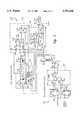
- FIG. 2is a schematic diagram of power transistor driver of FIG. 1;
- FIG. 3is a timing diagram depicting input voltages and output states of various components in the circuitry of FIG. 2.
- Power transistor driver 10is generally comprised of a transformer 12 having a primary winding connected to a grounded circuit 14, and a secondary winding connected to an isolated circuit 16.
- the output of the isolated circuitis connected to a power transistor 18, such as a MOSFET or IGBT, whose drain is connected to a power supply 20, and whose source is the output of driver 10.
- the source of power transistor 18is connected to the electrode to be applied to the heart attack victim.
- a high voltage pulseis generated at the electrode upon receipt of a control signal by grounded circuit 14.
- Driver 10uses transformer 12 to couple the signal as well as power to the components in isolated circuit 16.
- the present inventionuses frequency switching, or shifting, as the control signal.
- a 2:1 multiplexer 22selects between driving isolation transformer 12 at one of two frequencies, Freq or Freq/2.
- the output of multiplexer 22passes through resistor 24 to the base of a transistor 26.
- the emitter of transistor 26is connected to ground, and the collector is connected to the primary winding of transformer 12, which is further connected to a low power (e.g., 12 volt) supply 28.
- the secondary winding of transformer 12is thus energized at the output frequency of multiplexer 22.
- a voltage rectifier 30 on the secondaryis used to generate isolated power. This supply is used to power a frequency detector circuit 32 and a transistor driver circuit 34. Frequency detect circuit 32 discriminates between Freq and Freq/2, and its output is transmitted to transistor driver circuit 34 synchronous with a clock edge. Voltage rectifier 30, frequency detector circuit 32 and transistor driver circuit 34 all use low power components that allow for a physically small (and less expensive) isolation transformer 12.
- Multiplexer 22includes two flip-flops 36 and 38, and gates 40, 42 and 44.
- Flip-flop 36is configured as a divide-by-2 circuit, with the output Q connected to one input of gate 40. From a master clock input, this allows the generation of Freq and Freq/2.
- Flip-flop 38is used to synchronize the switch control input signal with the clock signal. Its outputs Q and Q are connected to one input each of gates 40 and 42. The other input of gate 42 is connected to the clock signal.
- Gates 40, 42 and 44are NOR gates, configured as a 2:1 multiplexer. The output of this multiplexer switches between high and low states at either Freq or Freq/2, depending upon the input of the switch control signal, turning transistor 26 on and off at the corresponding frequency.
- transformer 12The secondary of transformer 12 is thereby energized at either Freq or Freq/2.
- Transformer 12is configured in the flyback mode.
- a secondary voltage (V cc )is developed using diode 46 and capacitor 48 as a rectifier. This output voltage is a function of the transformer turns ratio, input voltage, and duty cycle. Output voltage is not critical, so long as sufficient gate voltage is developed to turn on power transistor 18 (10 to 20 volts is adequate).
- a regulated 5 volt supplyis generated using an LM78L05 chip 50. Secondary current consumption is very low, kept under 3 mA, allowing for the very small isolation transformer.
- Inverter 52is used to buffer the secondary flyback signal. This buffer is powered by the regulated 5 volt supply, providing a clean signal as input to the frequency detect circuitry. Resistor 54 and zener diode 56 limit the voltage at the input of the buffer, protecting it from overvoltage conditions.
- the output of inverter 52is connected in parallel with resistor 58 and diode 60 which are in turn connected to the negative input of comparator 62. The positive input is connected to the 5 volt reference via resistor 64, and to the secondary winding of transformer 12 via resistor 66.
- the output of comparator 62is coupled with the 5 volt reference via another resistor 68 to the input of another flip-flop 70. Comparator 62 and flip-flop 70 form the basis of the frequency detector. The other input of flip-flop 70 is connected to the output of inverter 52.
- the output Q of flip-flop 70is connected to the positive input of another comparator 72. Its negative input is connected to the 5 volt reference via resistor 64, and to the secondary winding of transformer 12 via resistor 66. Comparator 72 is used as a level shifter (5 volts to 15 volts). The output of comparator 72, which is coupled to V cc via resistor 74, drives the emitter follower of transistor 76, whose collector is also connected to V cc . The output of transistor 76, which is connected to the secondary winding of transformer 12 via another resistor 78, then drives power transistor 20.
- the timing diagram of FIG. 3is useful in understanding the operation of isolation circuit 16.
- the output of inverter 52feeds the simple integrator formed from resistor 58, diode 60 and a capacitor 80 which is connected to the negative input of comparator 62 and to the secondary winding of transformer 12.
- This circuithas a fast rise time as capacitor 80 is charged through diode 60, and a slow fall time as capacitor discharges through resistor 58.
- the output of this integratoris compared with a reference potential by comparator 62. As seen in the timing diagram, the output of comparator 62 will pulse high as the frequency at inverter 52 drops to Freq/2. This signal is then latched by flip-flop 70 on the rising edge of the signal from inverter 52.
- the on state of power transistor 18i.e., the pulse period for the signal from the output of flip-flop 70
- the pulse period for the signal from the output of flip-flop 70should last at least 10 ms, and preferably lasts about 15 ms. This period may be provided by using a clock having a frequency of 200 kHz (Freq), a switch control signal lasting about 2-20 ms (a biphasic or monophasic truncated waveform).
- the minimum pulse width for this exemplary circuitis one cycle of Freq/2, or 10 ⁇ s.
Landscapes
- Engineering & Computer Science (AREA)
- Power Engineering (AREA)
- Dc-Dc Converters (AREA)
Abstract
Description
Claims (16)
Priority Applications (1)
| Application Number | Priority Date | Filing Date | Title |
|---|---|---|---|
| US08/742,787US5781040A (en) | 1996-10-31 | 1996-10-31 | Transformer isolated driver for power transistor using frequency switching as the control signal |
Applications Claiming Priority (1)
| Application Number | Priority Date | Filing Date | Title |
|---|---|---|---|
| US08/742,787US5781040A (en) | 1996-10-31 | 1996-10-31 | Transformer isolated driver for power transistor using frequency switching as the control signal |
Publications (1)
| Publication Number | Publication Date |
|---|---|
| US5781040Atrue US5781040A (en) | 1998-07-14 |
Family
ID=24986226
Family Applications (1)
| Application Number | Title | Priority Date | Filing Date |
|---|---|---|---|
| US08/742,787Expired - Fee RelatedUS5781040A (en) | 1996-10-31 | 1996-10-31 | Transformer isolated driver for power transistor using frequency switching as the control signal |
Country Status (1)
| Country | Link |
|---|---|
| US (1) | US5781040A (en) |
Cited By (51)
| Publication number | Priority date | Publication date | Assignee | Title |
|---|---|---|---|---|
| US20010044640A1 (en)* | 2000-03-22 | 2001-11-22 | Naoto Akiyama | Semiconductor switch driving circuit |
| US6384588B1 (en) | 2000-04-13 | 2002-05-07 | Daniel F. Mulhauser | Method and apparatus for asymmetrically inducing voltages in transformer secondary windings while avoiding saturation of the transformer core |
| US6411136B1 (en)* | 1998-03-02 | 2002-06-25 | Telefonaktiebolaget Lm Ericsson (Publ) | Differential line driver |
| US6441513B1 (en) | 2000-04-13 | 2002-08-27 | Koninklijke Philips Electronics N.V. | Method and apparatus for rapid, synchronized, and isolated transistor switching |
| US20060006922A1 (en)* | 2004-04-19 | 2006-01-12 | Infineon Technologies Ag | Circuit arrangement having a power transistor and a drive circuit for the power transistor |
| US20080224636A1 (en)* | 2007-03-12 | 2008-09-18 | Melanson John L | Power control system for current regulated light sources |
| US20080224631A1 (en)* | 2007-03-12 | 2008-09-18 | Melanson John L | Color variations in a dimmable lighting device with stable color temperature light sources |
| US20080240789A1 (en)* | 2007-03-28 | 2008-10-02 | Fuji Xerox Co., Ltd. | Rotator for powder conveyance and toner cartridge |
| US20080272747A1 (en)* | 2007-05-02 | 2008-11-06 | Cirrus Logic, Inc. | Programmable power control system |
| US20090147544A1 (en)* | 2007-12-11 | 2009-06-11 | Melanson John L | Modulated transformer-coupled gate control signaling method and apparatus |
| WO2009076329A1 (en)* | 2007-12-11 | 2009-06-18 | Cirrus Logic, Inc. | History-independent noise-immune modulated transformer-coupled gate control signaling method and apparatus |
| US20090190384A1 (en)* | 2008-01-30 | 2009-07-30 | Cirrus Logic, Inc. | Powering a power supply integrated circuit with sense current |
| US20090189579A1 (en)* | 2008-01-30 | 2009-07-30 | Melanson John L | Switch state controller with a sense current generated operating voltage |
| US20090191837A1 (en)* | 2008-01-30 | 2009-07-30 | Kartik Nanda | Delta Sigma Modulator with Unavailable Output Values |
| US20090212759A1 (en)* | 2008-02-26 | 2009-08-27 | Melanson John L | Transformer-isolated analog-to-digital converter (adc) feedback apparatus and method |
| EP1633046A3 (en)* | 2004-09-01 | 2009-10-21 | Kabushiki Kaisha Toshiba | Digital signal transfer device |
| US20090322300A1 (en)* | 2008-06-25 | 2009-12-31 | Melanson John L | Hysteretic buck converter having dynamic thresholds |
| US20100060202A1 (en)* | 2007-03-12 | 2010-03-11 | Melanson John L | Lighting System with Lighting Dimmer Output Mapping |
| US20100079125A1 (en)* | 2008-07-25 | 2010-04-01 | Melanson John L | Current sensing in a switching power converter |
| US20100079124A1 (en)* | 2008-09-30 | 2010-04-01 | John Laurence Melanson | Adjustable Constant Current Source with Continuous Conduction Mode ("CCM") and Discontinuous Conduction Mode ("DCM") Operation |
| US20100148677A1 (en)* | 2008-12-12 | 2010-06-17 | Melanson John L | Time division light output sensing and brightness adjustment for different spectra of light emitting diodes |
| US20100164406A1 (en)* | 2008-07-25 | 2010-07-01 | Kost Michael A | Switching power converter control with triac-based leading edge dimmer compatibility |
| US7759881B1 (en) | 2008-03-31 | 2010-07-20 | Cirrus Logic, Inc. | LED lighting system with a multiple mode current control dimming strategy |
| US20100277072A1 (en)* | 2009-04-30 | 2010-11-04 | Draper William A | Calibration Of Lamps |
| US20100328976A1 (en)* | 2009-06-30 | 2010-12-30 | Melanson John L | Cascode configured switching using at least one low breakdown voltage internal, integrated circuit switch to control at least one high breakdown voltage external switch |
| US20100327838A1 (en)* | 2009-06-30 | 2010-12-30 | Melanson John L | Switching power converter with current sensing transformer auxiliary power supply |
| US20110074302A1 (en)* | 2009-09-30 | 2011-03-31 | Draper William A | Phase Control Dimming Compatible Lighting Systems |
| WO2010061281A3 (en)* | 2008-11-27 | 2011-05-05 | Toyota Jidosha Kabushiki Kaisha | Electrically insulated switching element driver and method for controlling same |
| US20110110000A1 (en)* | 2009-11-09 | 2011-05-12 | Etter Brett E | Power System Having Voltage-Based Monitoring for Over Current Protection |
| US20110115400A1 (en)* | 2009-11-17 | 2011-05-19 | Harrison Daniel J | Led dimmer control |
| US7994863B2 (en) | 2008-12-31 | 2011-08-09 | Cirrus Logic, Inc. | Electronic system having common mode voltage range enhancement |
| US8008898B2 (en) | 2008-01-30 | 2011-08-30 | Cirrus Logic, Inc. | Switching regulator with boosted auxiliary winding supply |
| US8014176B2 (en) | 2008-07-25 | 2011-09-06 | Cirrus Logic, Inc. | Resonant switching power converter with burst mode transition shaping |
| US8018171B1 (en) | 2007-03-12 | 2011-09-13 | Cirrus Logic, Inc. | Multi-function duty cycle modifier |
| US8076920B1 (en) | 2007-03-12 | 2011-12-13 | Cirrus Logic, Inc. | Switching power converter and control system |
| US8102127B2 (en) | 2007-06-24 | 2012-01-24 | Cirrus Logic, Inc. | Hybrid gas discharge lamp-LED lighting system |
| US8212493B2 (en) | 2009-06-30 | 2012-07-03 | Cirrus Logic, Inc. | Low energy transfer mode for auxiliary power supply operation in a cascaded switching power converter |
| US8222872B1 (en) | 2008-09-30 | 2012-07-17 | Cirrus Logic, Inc. | Switching power converter with selectable mode auxiliary power supply |
| US8288954B2 (en) | 2008-12-07 | 2012-10-16 | Cirrus Logic, Inc. | Primary-side based control of secondary-side current for a transformer |
| US8362707B2 (en) | 2008-12-12 | 2013-01-29 | Cirrus Logic, Inc. | Light emitting diode based lighting system with time division ambient light feedback response |
| US8487546B2 (en) | 2008-08-29 | 2013-07-16 | Cirrus Logic, Inc. | LED lighting system with accurate current control |
| US20140013129A1 (en)* | 2012-07-09 | 2014-01-09 | L. Pierre de Rochemont | Hybrid computing module |
| US8963535B1 (en) | 2009-06-30 | 2015-02-24 | Cirrus Logic, Inc. | Switch controlled current sensing using a hall effect sensor |
| US9161415B2 (en) | 2009-01-13 | 2015-10-13 | Terralux, Inc. | Method and device for remote sensing and control of LED lights |
| US9192011B2 (en) | 2011-12-16 | 2015-11-17 | Terralux, Inc. | Systems and methods of applying bleed circuits in LED lamps |
| US9265119B2 (en) | 2013-06-17 | 2016-02-16 | Terralux, Inc. | Systems and methods for providing thermal fold-back to LED lights |
| US9326346B2 (en) | 2009-01-13 | 2016-04-26 | Terralux, Inc. | Method and device for remote sensing and control of LED lights |
| CN105703755A (en)* | 2014-12-12 | 2016-06-22 | 三星Sdi株式会社 | Gate driver and method of driving the same |
| US20170040994A1 (en)* | 2015-03-30 | 2017-02-09 | Halliburton Energy Services, Inc. | Simplified gate driver for power transistors |
| US20170047926A1 (en)* | 2015-03-30 | 2017-02-16 | Halliburton Energy Services, Inc. | Simplified gate driver for power transistors |
| US10051701B2 (en) | 2014-07-16 | 2018-08-14 | Philips Lighting Holding B.V. | Systems and methods for maintaining dimmer behavior in a low-power lamp assembly |
Citations (1)
| Publication number | Priority date | Publication date | Assignee | Title |
|---|---|---|---|---|
| US5469098A (en)* | 1993-03-29 | 1995-11-21 | Exide Electronics Corporation | Isolated gate drive |
- 1996
- 1996-10-31USUS08/742,787patent/US5781040A/ennot_activeExpired - Fee Related
Patent Citations (1)
| Publication number | Priority date | Publication date | Assignee | Title |
|---|---|---|---|---|
| US5469098A (en)* | 1993-03-29 | 1995-11-21 | Exide Electronics Corporation | Isolated gate drive |
Cited By (98)
| Publication number | Priority date | Publication date | Assignee | Title |
|---|---|---|---|---|
| US6411136B1 (en)* | 1998-03-02 | 2002-06-25 | Telefonaktiebolaget Lm Ericsson (Publ) | Differential line driver |
| US20010044640A1 (en)* | 2000-03-22 | 2001-11-22 | Naoto Akiyama | Semiconductor switch driving circuit |
| EP1143619A3 (en)* | 2000-03-22 | 2002-02-06 | Nihon Kohden Corporation | Semiconductor switch driving circuit |
| US6836161B2 (en) | 2000-03-22 | 2004-12-28 | Nihon Kohden Corporation | Semiconductor switch driving circuit |
| US6384588B1 (en) | 2000-04-13 | 2002-05-07 | Daniel F. Mulhauser | Method and apparatus for asymmetrically inducing voltages in transformer secondary windings while avoiding saturation of the transformer core |
| US6441513B1 (en) | 2000-04-13 | 2002-08-27 | Koninklijke Philips Electronics N.V. | Method and apparatus for rapid, synchronized, and isolated transistor switching |
| US20060006922A1 (en)* | 2004-04-19 | 2006-01-12 | Infineon Technologies Ag | Circuit arrangement having a power transistor and a drive circuit for the power transistor |
| US7408398B2 (en)* | 2004-04-19 | 2008-08-05 | Infineon Technologies Ag | Circuit arrangement having a power transistor and a drive circuit for the power transistor |
| EP1633046A3 (en)* | 2004-09-01 | 2009-10-21 | Kabushiki Kaisha Toshiba | Digital signal transfer device |
| US8018171B1 (en) | 2007-03-12 | 2011-09-13 | Cirrus Logic, Inc. | Multi-function duty cycle modifier |
| US20080224636A1 (en)* | 2007-03-12 | 2008-09-18 | Melanson John L | Power control system for current regulated light sources |
| US8174204B2 (en) | 2007-03-12 | 2012-05-08 | Cirrus Logic, Inc. | Lighting system with power factor correction control data determined from a phase modulated signal |
| US8076920B1 (en) | 2007-03-12 | 2011-12-13 | Cirrus Logic, Inc. | Switching power converter and control system |
| US20080224629A1 (en)* | 2007-03-12 | 2008-09-18 | Melanson John L | Lighting system with power factor correction control data determined from a phase modulated signal |
| US20080224631A1 (en)* | 2007-03-12 | 2008-09-18 | Melanson John L | Color variations in a dimmable lighting device with stable color temperature light sources |
| US8536794B2 (en) | 2007-03-12 | 2013-09-17 | Cirrus Logic, Inc. | Lighting system with lighting dimmer output mapping |
| US7852017B1 (en) | 2007-03-12 | 2010-12-14 | Cirrus Logic, Inc. | Ballast for light emitting diode light sources |
| US7804256B2 (en) | 2007-03-12 | 2010-09-28 | Cirrus Logic, Inc. | Power control system for current regulated light sources |
| US20100060202A1 (en)* | 2007-03-12 | 2010-03-11 | Melanson John L | Lighting System with Lighting Dimmer Output Mapping |
| US20080240789A1 (en)* | 2007-03-28 | 2008-10-02 | Fuji Xerox Co., Ltd. | Rotator for powder conveyance and toner cartridge |
| US7969125B2 (en) | 2007-05-02 | 2011-06-28 | Cirrus Logic, Inc. | Programmable power control system |
| US20080273356A1 (en)* | 2007-05-02 | 2008-11-06 | Melanson John L | Switching Power Converter with Efficient Switching Control Signal Period Generation |
| US20080272746A1 (en)* | 2007-05-02 | 2008-11-06 | Cirrus Logic, Inc. | Power factor correction controller with switch node feedback |
| US7894216B2 (en) | 2007-05-02 | 2011-02-22 | Cirrus Logic, Inc. | Switching power converter with efficient switching control signal period generation |
| US20080272747A1 (en)* | 2007-05-02 | 2008-11-06 | Cirrus Logic, Inc. | Programmable power control system |
| US7888922B2 (en) | 2007-05-02 | 2011-02-15 | Cirrus Logic, Inc. | Power factor correction controller with switch node feedback |
| US7863828B2 (en) | 2007-05-02 | 2011-01-04 | Cirrus Logic, Inc. | Power supply DC voltage offset detector |
| US8125805B1 (en) | 2007-05-02 | 2012-02-28 | Cirrus Logic Inc. | Switch-mode converter operating in a hybrid discontinuous conduction mode (DCM)/continuous conduction mode (CCM) that uses double or more pulses in a switching period |
| US8120341B2 (en) | 2007-05-02 | 2012-02-21 | Cirrus Logic, Inc. | Switching power converter with switch control pulse width variability at low power demand levels |
| US8040703B2 (en) | 2007-05-02 | 2011-10-18 | Cirrus Logic, Inc. | Power factor correction controller with feedback reduction |
| US20080272758A1 (en)* | 2007-05-02 | 2008-11-06 | Melanson John L | Switching Power Converter with Switch Control Pulse Width Variability at Low Power Demand Levels |
| US20080272756A1 (en)* | 2007-05-02 | 2008-11-06 | Melanson John L | Power factor correction controller with digital fir filter output voltage sampling |
| US7821237B2 (en) | 2007-05-02 | 2010-10-26 | Cirrus Logic, Inc. | Power factor correction (PFC) controller and method using a finite state machine to adjust the duty cycle of a PWM control signal |
| US8102127B2 (en) | 2007-06-24 | 2012-01-24 | Cirrus Logic, Inc. | Hybrid gas discharge lamp-LED lighting system |
| US7656687B2 (en) | 2007-12-11 | 2010-02-02 | Cirrus Logic, Inc. | Modulated transformer-coupled gate control signaling method and apparatus |
| US7804697B2 (en) | 2007-12-11 | 2010-09-28 | Cirrus Logic, Inc. | History-independent noise-immune modulated transformer-coupled gate control signaling method and apparatus |
| US20090147544A1 (en)* | 2007-12-11 | 2009-06-11 | Melanson John L | Modulated transformer-coupled gate control signaling method and apparatus |
| WO2009076329A1 (en)* | 2007-12-11 | 2009-06-18 | Cirrus Logic, Inc. | History-independent noise-immune modulated transformer-coupled gate control signaling method and apparatus |
| US20090191837A1 (en)* | 2008-01-30 | 2009-07-30 | Kartik Nanda | Delta Sigma Modulator with Unavailable Output Values |
| US7755525B2 (en) | 2008-01-30 | 2010-07-13 | Cirrus Logic, Inc. | Delta sigma modulator with unavailable output values |
| US8576589B2 (en) | 2008-01-30 | 2013-11-05 | Cirrus Logic, Inc. | Switch state controller with a sense current generated operating voltage |
| US20090190384A1 (en)* | 2008-01-30 | 2009-07-30 | Cirrus Logic, Inc. | Powering a power supply integrated circuit with sense current |
| US20090189579A1 (en)* | 2008-01-30 | 2009-07-30 | Melanson John L | Switch state controller with a sense current generated operating voltage |
| US8022683B2 (en) | 2008-01-30 | 2011-09-20 | Cirrus Logic, Inc. | Powering a power supply integrated circuit with sense current |
| US8008898B2 (en) | 2008-01-30 | 2011-08-30 | Cirrus Logic, Inc. | Switching regulator with boosted auxiliary winding supply |
| US7796076B2 (en) | 2008-02-26 | 2010-09-14 | Cirrus Logic, Inc. | Transformer-isolated analog-to-digital converter (ADC) feedback apparatus and method |
| US20090212759A1 (en)* | 2008-02-26 | 2009-08-27 | Melanson John L | Transformer-isolated analog-to-digital converter (adc) feedback apparatus and method |
| US7759881B1 (en) | 2008-03-31 | 2010-07-20 | Cirrus Logic, Inc. | LED lighting system with a multiple mode current control dimming strategy |
| US8008902B2 (en) | 2008-06-25 | 2011-08-30 | Cirrus Logic, Inc. | Hysteretic buck converter having dynamic thresholds |
| US20090322300A1 (en)* | 2008-06-25 | 2009-12-31 | Melanson John L | Hysteretic buck converter having dynamic thresholds |
| US8553430B2 (en) | 2008-07-25 | 2013-10-08 | Cirrus Logic, Inc. | Resonant switching power converter with adaptive dead time control |
| US8279628B2 (en) | 2008-07-25 | 2012-10-02 | Cirrus Logic, Inc. | Audible noise suppression in a resonant switching power converter |
| US8344707B2 (en) | 2008-07-25 | 2013-01-01 | Cirrus Logic, Inc. | Current sensing in a switching power converter |
| US8014176B2 (en) | 2008-07-25 | 2011-09-06 | Cirrus Logic, Inc. | Resonant switching power converter with burst mode transition shaping |
| US20100079125A1 (en)* | 2008-07-25 | 2010-04-01 | Melanson John L | Current sensing in a switching power converter |
| US8212491B2 (en) | 2008-07-25 | 2012-07-03 | Cirrus Logic, Inc. | Switching power converter control with triac-based leading edge dimmer compatibility |
| US20100164406A1 (en)* | 2008-07-25 | 2010-07-01 | Kost Michael A | Switching power converter control with triac-based leading edge dimmer compatibility |
| US8487546B2 (en) | 2008-08-29 | 2013-07-16 | Cirrus Logic, Inc. | LED lighting system with accurate current control |
| US20100079124A1 (en)* | 2008-09-30 | 2010-04-01 | John Laurence Melanson | Adjustable Constant Current Source with Continuous Conduction Mode ("CCM") and Discontinuous Conduction Mode ("DCM") Operation |
| US8179110B2 (en) | 2008-09-30 | 2012-05-15 | Cirrus Logic Inc. | Adjustable constant current source with continuous conduction mode (“CCM”) and discontinuous conduction mode (“DCM”) operation |
| US8222872B1 (en) | 2008-09-30 | 2012-07-17 | Cirrus Logic, Inc. | Switching power converter with selectable mode auxiliary power supply |
| US8054654B2 (en) | 2008-11-27 | 2011-11-08 | Toyota Jidosha Kabushiki Kaisha | Electrically insulated switching element driver and method for controlling same |
| CN102227875B (en)* | 2008-11-27 | 2013-09-04 | 丰田自动车株式会社 | Electric isolation type switching element driving device and control method thereof |
| US20110222316A1 (en)* | 2008-11-27 | 2011-09-15 | Toyota Jidosha Kabushiki Kaisha | Electrically insulated switching element driver and method for controlling same |
| WO2010061281A3 (en)* | 2008-11-27 | 2011-05-05 | Toyota Jidosha Kabushiki Kaisha | Electrically insulated switching element driver and method for controlling same |
| US8288954B2 (en) | 2008-12-07 | 2012-10-16 | Cirrus Logic, Inc. | Primary-side based control of secondary-side current for a transformer |
| US8299722B2 (en) | 2008-12-12 | 2012-10-30 | Cirrus Logic, Inc. | Time division light output sensing and brightness adjustment for different spectra of light emitting diodes |
| US20100148677A1 (en)* | 2008-12-12 | 2010-06-17 | Melanson John L | Time division light output sensing and brightness adjustment for different spectra of light emitting diodes |
| US8362707B2 (en) | 2008-12-12 | 2013-01-29 | Cirrus Logic, Inc. | Light emitting diode based lighting system with time division ambient light feedback response |
| US7994863B2 (en) | 2008-12-31 | 2011-08-09 | Cirrus Logic, Inc. | Electronic system having common mode voltage range enhancement |
| US9560711B2 (en) | 2009-01-13 | 2017-01-31 | Terralux, Inc. | Method and device for remote sensing and control of LED lights |
| US9326346B2 (en) | 2009-01-13 | 2016-04-26 | Terralux, Inc. | Method and device for remote sensing and control of LED lights |
| US9161415B2 (en) | 2009-01-13 | 2015-10-13 | Terralux, Inc. | Method and device for remote sensing and control of LED lights |
| US8482223B2 (en) | 2009-04-30 | 2013-07-09 | Cirrus Logic, Inc. | Calibration of lamps |
| US20100277072A1 (en)* | 2009-04-30 | 2010-11-04 | Draper William A | Calibration Of Lamps |
| US8198874B2 (en) | 2009-06-30 | 2012-06-12 | Cirrus Logic, Inc. | Switching power converter with current sensing transformer auxiliary power supply |
| US20100327838A1 (en)* | 2009-06-30 | 2010-12-30 | Melanson John L | Switching power converter with current sensing transformer auxiliary power supply |
| US20100328976A1 (en)* | 2009-06-30 | 2010-12-30 | Melanson John L | Cascode configured switching using at least one low breakdown voltage internal, integrated circuit switch to control at least one high breakdown voltage external switch |
| US8248145B2 (en) | 2009-06-30 | 2012-08-21 | Cirrus Logic, Inc. | Cascode configured switching using at least one low breakdown voltage internal, integrated circuit switch to control at least one high breakdown voltage external switch |
| US8212493B2 (en) | 2009-06-30 | 2012-07-03 | Cirrus Logic, Inc. | Low energy transfer mode for auxiliary power supply operation in a cascaded switching power converter |
| US8963535B1 (en) | 2009-06-30 | 2015-02-24 | Cirrus Logic, Inc. | Switch controlled current sensing using a hall effect sensor |
| US9155174B2 (en) | 2009-09-30 | 2015-10-06 | Cirrus Logic, Inc. | Phase control dimming compatible lighting systems |
| US20110074302A1 (en)* | 2009-09-30 | 2011-03-31 | Draper William A | Phase Control Dimming Compatible Lighting Systems |
| US8654483B2 (en) | 2009-11-09 | 2014-02-18 | Cirrus Logic, Inc. | Power system having voltage-based monitoring for over current protection |
| US20110110000A1 (en)* | 2009-11-09 | 2011-05-12 | Etter Brett E | Power System Having Voltage-Based Monitoring for Over Current Protection |
| US9668306B2 (en) | 2009-11-17 | 2017-05-30 | Terralux, Inc. | LED thermal management |
| US20110115400A1 (en)* | 2009-11-17 | 2011-05-19 | Harrison Daniel J | Led dimmer control |
| US10485062B2 (en) | 2009-11-17 | 2019-11-19 | Ledvance Llc | LED power-supply detection and control |
| US9192011B2 (en) | 2011-12-16 | 2015-11-17 | Terralux, Inc. | Systems and methods of applying bleed circuits in LED lamps |
| US20140013129A1 (en)* | 2012-07-09 | 2014-01-09 | L. Pierre de Rochemont | Hybrid computing module |
| US9265119B2 (en) | 2013-06-17 | 2016-02-16 | Terralux, Inc. | Systems and methods for providing thermal fold-back to LED lights |
| US10051701B2 (en) | 2014-07-16 | 2018-08-14 | Philips Lighting Holding B.V. | Systems and methods for maintaining dimmer behavior in a low-power lamp assembly |
| CN105703755A (en)* | 2014-12-12 | 2016-06-22 | 三星Sdi株式会社 | Gate driver and method of driving the same |
| US9614512B2 (en)* | 2014-12-12 | 2017-04-04 | Samsung Sdi Co., Ltd. | Gate driver and method of driving the same |
| US20170040994A1 (en)* | 2015-03-30 | 2017-02-09 | Halliburton Energy Services, Inc. | Simplified gate driver for power transistors |
| US20170047926A1 (en)* | 2015-03-30 | 2017-02-16 | Halliburton Energy Services, Inc. | Simplified gate driver for power transistors |
| US9685947B2 (en)* | 2015-03-30 | 2017-06-20 | Halliburton Energy Services, Inc. | Simplified gate driver for power transistors |
| US9692409B2 (en)* | 2015-03-30 | 2017-06-27 | Halliburton Energy Services, Inc. | Simplified gate driver for power transistors |
Similar Documents
| Publication | Publication Date | Title |
|---|---|---|
| US5781040A (en) | Transformer isolated driver for power transistor using frequency switching as the control signal | |
| EP0782373B1 (en) | Method and apparatus for driving capacitive light emitting device | |
| US5543740A (en) | Integrated half-bridge driver circuit | |
| US5463283A (en) | Drive circuit for electroluminescent lamp | |
| US4694206A (en) | Drive circuit for a power field effect transistor | |
| US5939927A (en) | Isolated pulse mode driver for power transistor | |
| US4208595A (en) | Substrate generator | |
| JP2000505997A (en) | High voltage AC to low voltage DC converter | |
| US5686797A (en) | Electronluminescent lamp inverter | |
| US7663351B2 (en) | Synchronization circuitry for multiple power converters coupled at a common node | |
| JPH07500720A (en) | Transformer isolated FET drive circuit with 0-100% duty cycle | |
| US5172032A (en) | Method of and apparatus for the energization of electroluminescent lamps | |
| EP0531941B1 (en) | Method and driver for power field-effect switches with refreshed power supply providing stable on/off switching | |
| PT93364A (en) | COMUTATIVE MODULE POWER SUPPLY UNIT WITH FUNCTIONING OF PRONOUNCE MODE OF IMPULSE | |
| KR900011437A (en) | Output control method and system of X-ray generator | |
| US6091164A (en) | Single inverter with dual boost | |
| US4158224A (en) | Inverter apparatus | |
| JPS57156680A (en) | Inverter device | |
| JP3133964B2 (en) | Insulated gate drive circuit | |
| JPH1028375A (en) | Switching power supply | |
| US5717317A (en) | Circuit for energizing electroluminescent panel | |
| JPS6319021A (en) | Voltage controller | |
| KR101739551B1 (en) | Switch control device | |
| JPS62145619A (en) | Magnetic contactor coil excitation circuit | |
| US6271653B1 (en) | Power supply operable with wide input range |
Legal Events
| Date | Code | Title | Description |
|---|---|---|---|
| AS | Assignment | Owner name:HEWLETT-PACKARD COMPANY, CALIFORNIA Free format text:ASSIGNMENT OF ASSIGNORS INTEREST;ASSIGNOR:MYERS, RICHARD C.;REEL/FRAME:008368/0775 Effective date:19961031 | |
| AS | Assignment | Owner name:HEWLETT-PACKARD COMPANY, A DELAWARE CORPORATION, C Free format text:MERGER;ASSIGNOR:HEWLETT-PACKARD COMPANY, A CALIFORNIA CORPORATION;REEL/FRAME:010841/0649 Effective date:19980520 | |
| AS | Assignment | Owner name:AGILENT TECHNOLOGIES INC, CALIFORNIA Free format text:ASSIGNMENT OF ASSIGNORS INTEREST;ASSIGNOR:HEWLETT-PACKARD COMPANY;REEL/FRAME:010977/0540 Effective date:19991101 | |
| FPAY | Fee payment | Year of fee payment:4 | |
| AS | Assignment | Owner name:KONINKLIJKE PHILIPS ELECTRONICS N.V., NETHERLANDS Free format text:ASSIGNMENT OF ASSIGNORS INTEREST;ASSIGNOR:AGILENT TECHNOLOGIES, INC.;REEL/FRAME:014662/0179 Effective date:20010801 | |
| REMI | Maintenance fee reminder mailed | ||
| LAPS | Lapse for failure to pay maintenance fees | ||
| STCH | Information on status: patent discontinuation | Free format text:PATENT EXPIRED DUE TO NONPAYMENT OF MAINTENANCE FEES UNDER 37 CFR 1.362 | |
| FP | Lapsed due to failure to pay maintenance fee | Effective date:20060714 | |
| AS | Assignment | Owner name:KONINKLIJKE PHILIPS ELECTRONICS N V, NETHERLANDS Free format text:ASSIGNMENT OF ASSIGNORS INTEREST;ASSIGNOR:AGILENT TECHNOLOGIES, INC.;REEL/FRAME:022835/0572 Effective date:20090610 |