US5781024A - Instrument performance verification system - Google Patents
Instrument performance verification systemDownload PDFInfo
- Publication number
- US5781024A US5781024AUS08/687,687US68768796AUS5781024AUS 5781024 AUS5781024 AUS 5781024AUS 68768796 AUS68768796 AUS 68768796AUS 5781024 AUS5781024 AUS 5781024A
- Authority
- US
- United States
- Prior art keywords
- electronic circuit
- instrument
- verification system
- performance
- leakage
- Prior art date
- Legal status (The legal status is an assumption and is not a legal conclusion. Google has not performed a legal analysis and makes no representation as to the accuracy of the status listed.)
- Expired - Lifetime
Links
Images


Classifications
- G—PHYSICS
- G01—MEASURING; TESTING
- G01R—MEASURING ELECTRIC VARIABLES; MEASURING MAGNETIC VARIABLES
- G01R31/00—Arrangements for testing electric properties; Arrangements for locating electric faults; Arrangements for electrical testing characterised by what is being tested not provided for elsewhere
- G01R31/28—Testing of electronic circuits, e.g. by signal tracer
- G01R31/282—Testing of electronic circuits specially adapted for particular applications not provided for elsewhere
- G01R31/2829—Testing of circuits in sensor or actuator systems
- A—HUMAN NECESSITIES
- A61—MEDICAL OR VETERINARY SCIENCE; HYGIENE
- A61B—DIAGNOSIS; SURGERY; IDENTIFICATION
- A61B5/00—Measuring for diagnostic purposes; Identification of persons
- A—HUMAN NECESSITIES
- A61—MEDICAL OR VETERINARY SCIENCE; HYGIENE
- A61B—DIAGNOSIS; SURGERY; IDENTIFICATION
- A61B5/00—Measuring for diagnostic purposes; Identification of persons
- A61B5/145—Measuring characteristics of blood in vivo, e.g. gas concentration or pH-value ; Measuring characteristics of body fluids or tissues, e.g. interstitial fluid or cerebral tissue
- A61B5/1495—Calibrating or testing of in-vivo probes
- A—HUMAN NECESSITIES
- A61—MEDICAL OR VETERINARY SCIENCE; HYGIENE
- A61B—DIAGNOSIS; SURGERY; IDENTIFICATION
- A61B2560/00—Constructional details of operational features of apparatus; Accessories for medical measuring apparatus
- A61B2560/02—Operational features
- A61B2560/0242—Operational features adapted to measure environmental factors, e.g. temperature, pollution
- A61B2560/0247—Operational features adapted to measure environmental factors, e.g. temperature, pollution for compensation or correction of the measured physiological value
- A61B2560/0257—Operational features adapted to measure environmental factors, e.g. temperature, pollution for compensation or correction of the measured physiological value using atmospheric pressure
Definitions
- This inventionrelates generally to diagnostic testing instruments, and more particularly, to an electronic system and method incorporated integral to the diagnostic instrument for verifying the performance of the instrument.
- the instrument performance verification systemis activated periodically or manually to detect any changes in the integrity of the diagnostic instrument, thereby assuring and maintaining the accuracy of the analysis conducted by the diagnostic instrument.
- a blood analyzeris one example of a diagnostic instrument that may use standardized control samples to determine its operating quality.
- the typical blood analyzerhas electrochemical sensors that are used to test for blood constituents such as blood gases and other species in a sample.
- Diagnostic systemsare known in which a plurality of electrochemical sensors have been built into a single use disposable cartridge. These sensors can be used to make a variety of measurements when in contact with, for example, a sample of blood.
- the hematocrit, for example, of the bloodmay be measured by determining the impedance (or its inverse, conductance) of the blood as measured between two electrodes of an electrochemical sensor.
- test unit for a system of this typeis disclosed by Zelin et al. in U.S. Pat. No. 5,124,661.
- a re-usable plug-in test cartridgeis used that introduces externally generated signals of known values that mimic several expected sensor signals to the diagnostic instrument. If the analyzing sensors and circuitry of the instrument are functioning properly, the expected signal output for each will be displayed.
- the system disclosed by Zelin et al.impresses simulated signals produced either from a single source and voltage divider resistor network using matched resistors or a second resistor network using multiple tied voltages. These networks supply a voltage step or multiple voltages to an amplifier or open circuit for testing. Simple resistors are employed to produce high impedance. Low voltage signals for simulating signals are produced by amperometric, conductometric and potentiometric sensors.
- the test cartridge system of Zelin et al.permits detection and discrimination between failures from damaged CMOS amplifiers and failures from current leakage in contaminated connectors, that system does not test for circuit leakage, leakage current, A/D reference voltage, temperature control, and edge connector contact resistance.
- a pressure transducer incorporating an internal control circuithas been disclosed by Reynolds et al. in U.S. Pat. No. 4,557,269.
- Reynolds et al.'s systemthe entire pressure transducer is discarded after one use, requiring calibration of the instrument before each test. The required calibration is patient specific and is not interchangeable between patients.
- the transducerincludes an electronic circuit having calibration resistors, the electronic circuit does not verify instrument performance. By testing for leakage to ground, pin to pin and background leakage, all potential areas of failure due to leakage would be identified. Hence, a system that tests for all types of leakage current would be beneficial.
- a performance verification system for such a diagnostic instrumentwould include an integral system that automatically determines the integrity of all aspects of the associated instrument, particularly a user friendly system that minimizes the need for externally connected testing devices. It would also be an advantage if each test signal were independently generated and not based on a common signal input. Further, it would be desirable for the test range to exceed the voltage/amperage range produced by the electrochemical sensors.
- a diagnostic instrument incorporating the system of the present inventionincludes a housing, a multi-channel connector, an electronic circuit board, a power supply, a control panel, an instrument performance verification system for analyzing output signals, and user interface or output means to indicate results obtained from said instrument performance verification means.
- An external test cartridgeis required to test the temperature control and edge connector contact circuit. The other verifications performed by the system are performed without the necessity of external components.
- the diagnostic instrument of the preferred embodimentuses electrochemical methods of sample testing. Certain species within the sample are identified by potentiometric sensors and other species are identified by amperometric sensors.
- a potentialis generated across a working electrode and a reference electrode.
- the reference electrodeis set to a first potential and stabilized by a counter electrode used to source the current.
- the potential between the electrodescauses a chemical reaction to occur proximate the electrode surfaces.
- the electrodes and generated potentialare selected such that the current generated across the electrodes is proportional to the amount of the selected analyte present in the sample.
- a DAC voltageis applied through a resistor of known resistance and the output is applied to the amperometric sensor input (at the working electrode).
- the sensor circuit outputis measured and compared to an expected value and a range of inputs are tested to assure linearity over the entire circuit's range.
- the potentiometric operational amplifiersare tested at levels that exceed expected operating levels, thereby verifying that the operational amplifiers exceed the requirements necessary to measure the outputs from the potentiometric sensors.
- a DAC voltageis directed through a resistor of known resistance and the output is applied to the selected operational amplifier. The output from the operational amplifier is measured and compared to the expected value.
- the multi-channel connectoris fixed to the housing as part of a system designed for mechanical and electrical connection to a multi-function disposable sensor cartridge device.
- the electronic circuit board within the diagnostic instrumentis electrically coupled to the multi-channel connector and power supply, and is contained within the housing.
- the electronic circuit boardincludes a means for analyzing output signals transmitted through said multi-channel connector and other components of the electronic circuit.
- the instrument performance verification system of the present inventionis a software controlled system that utilizes digital-to-analog converters (DACs) to apply voltages to measure high impedance regions and detect leakage current between channels.
- the DAC signalis generally a higher voltage signal than those produced by electrochemical sensors.
- DACsare further used to provide a low impedance signal for performance checking or checking the operation of the front-end amplifier system. Each signal is generated separately and is not tied to any other.
- the softwaredetermines the value of each applied signal. While the test signal sources connect to common conductors, the test signals are not sent through a mechanical connector device.
- the verification systemmay include but is not limited to one or more of the following subsystems: a means for testing a calibration of the cartridge temperature control system, means for detecting leakage to ground within the electronic circuit, means for detecting failure in operational amplifiers electrically coupled to the electronic circuit, means for detecting leakage between pins electrically coupled to the electronic circuit, means for determining failure in an amperometric sensor circuit, means for determining failure in an operational amplifier electrically coupled to the electronic circuit, means for determining failure in a conductivity sensor circuit, means for detecting failure in an AC source of a conductivity sensor circuit, and means for detecting failure in a band pass filter of a conductivity sensor circuit.
- the electronic circuitry of the verification systemis electrically coupled to a display or output means that indicates performance verification results.
- the useractivates the test sequence from a control panel, thereby initiating the internal test sequence to test the circuit integrity and performance of the diagnostic instrument.
- the internal test routineincludes the following steps: activating a test cycle, measuring various amounts of leakage current within the electronic circuit, analyzing the various amounts of measured leakage current, and indicating the results obtained from analyzing the various amounts of leakage current.
- Other testsmay include determining the A/D reference voltage of the electronic circuit, comparing the A/D reference voltage with a predetermined expected value, determining an integrity of the potentiometric sensor circuit (referred to as an Ion Selective Electrode (ISE) in the drawings) operational amplifier electrically coupled to the electronic circuit or other potentiometric circuit operational amplifier, comparing the integrity of the potentiometric circuit operational amplifier with a predetermined expected value, testing the performance of an amperometric sensor circuit, testing the performance of a hematocrit sensor circuit, testing a temperature control circuit coupled to the electronic circuit, and measuring an edge connector contact resistance of said electronic circuit.
- the internal testsallow the diagnostic instrument to be checked periodically or manually to insure that the circuitry and connectors are functioning properly, thereby avoiding inaccurate diagnostic measurements.
- Another object of the present inventionis to provide a method of internally checking the integrity of the electronic circuit.
- Still another object of the present inventionis to provide a passive external card for verifying the performance of the temperature control and edge connector contacts.
- Yet another object of the present inventionis to provide a diagnostic instrument that includes an internal means of checking the performance of the electronic circuit.
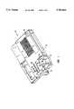
- FIG. 1is a perspective view of an analytical instrument which may incorporate the instrument performance verification system of the present invention
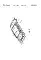
- FIG. 2is a perspective view of a test card used to verify the calibration of the temperature control system and performance of edge connector contacts of the instrument;
- FIG. 3is an exploded view of a test card of the type shown in FIG. 2;
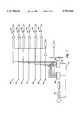
- FIG. 4is a schematic block diagram showing elements of a system employed in carrying out the invention.
- FIG. 5is a flow chart showing a test routine for the performance verification system of the present invention.
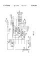
- FIGS. 6-7together present a schematic diagram of a portion of the electronic circuit of the performance verification system of the present invention.
- FIG. 8is a schematic diagram of the electronic circuit of the test card of FIGS. 2 and 3.
- FIG. 1shows generally a diagnostic instrument 10 which incorporates the electronic instrument performance verification system of the present invention.
- the diagnostic instrument 10includes a housing 12, display 14, control panel 16, power supply 18, cartridge receptacle 20, cartridge temperature control contacts 24, infrared (IR) probe 26, an array of card or cartridge connector contacts 28-46, and electronic circuit (not shown).
- FIGS. 6-7illustrate details of the portion of the electronic circuitry used to verify instrument performance.
- FIG. 2 and 3together show the test card used to verify the performance of the temperature control system and edge connector contacts of the diagnostic instrument 10.
- the test card 48includes a cover 50 and base 52.
- a test circuit board 54is retained between the cover 50 and base 52.
- An end of the circuit board 54 having lead connector pads 58-74extends and protrudes beneath the cover 50.
- An IR transparent probe window 76(see FIG. 3) is provided in base 52 to enable temperature sensing of the test circuit board 54.
- Guide rails 78 and 80guide the test card 48 into contact with the diagnostic instrument 10, wherein the connector contacts 28-46 engage the lead connector pads 56-74.
- the IR probe window 76aligns with the IR probe 26, allowing IR probe 26 to sense the temperature of the test card circuit board 54.
- Resistive heaters 82 electrically coupled to the ceramic test circuit boardare used to heat the board 54 to a control temperature.
- the temperature of the board 54is also measured by a thermistor 84, and the thermistor signal is compared to the corresponding value sensed by the IR probe as a check on the performance of the IR probe 26.
- FIG. 4further identifies the various components of the electronic circuit of the diagnostic instrument 10 of the present invention.
- an integrated circuit 86is electrically coupled to the display 14, control panel 16, digital to analog converters (DACs) generally represented by numeral 88, analog to digital (A/D) converters generally represented by numeral 90, beeper or alarm 92, printer 94, internal modem 96, and serial port interface 98.
- the DACs 88are electrically coupled to the sensor interface circuits 100 and temperature controls 102.
- a barometric pressure sensor 104is coupled to the A/D converter 90.
- test cycleAn overview of the process steps for controlling the verification system of the present invention is represented in block form by the flowchart of FIG. 5.
- the useractivates the test cycle using the control panel 16 (see block 110).
- a messagewill appear on the display 14, prompting the user to remove all sensor cartridges inserted in the diagnostic instrument 10.
- the instrument performance verification systemchecks to make sure that the connector contacts 28-46 within the cartridge or card receptacle 20 are open.
- the test cyclemay be activated automatically when a cartridge is removed from the cartridge receptacle 20, when a test card is inserted and the instrument is energized, or when the diagnostic instrument 10 is otherwise energized.
- the entire test routineis preferably implemented automatically once a cartridge is removed from the cartridge receptacle 20.
- a prompt on the display 14may change, indicating to the user the progress of the test.
- the resultsare indicated on the display 14 and optionally printed on an attached printer 94.
- the resultsare also stored within internal memory of the integrated circuit 86 for later recall or for down-loading to an external data management system or information system, thereby allowing the user to document and maintain test records. If the test indicates a failure of components of the diagnostic instrument 10, instructions may appear on the display 14, instructing the user on how to proceed to repair the failed components or device. Error codes giving specific failure information are stored for later recall, to assist in further diagnosing any problems detected.
- the systemis first directed to test for leakage current within the internal electronic circuitry of the instrument 10 and the connections to the instrument 10 (see block 112).
- Leakage current within the circuitrymay include background leakage, sensing-circuit leakage, pin to pin leakage, and/or pin to ground leakage.
- the A/D reference voltageis also determined and compared with the expected value at block 114. Accuracy of the A/D reference voltage is important since the measurements made by the instrument are based on the A/D reference voltage.
- each potentiometric circuit operational amplifieris tested at block 116. They are tested at levels that exceed expected operating levels to verify that the potentiometric circuit operational amplifiers exceed the requirements necessary to measure potentiometric sensor outputs. Various tests to determine the condition of the amperometric and conductometric (possibly hematocrit) sensor circuits are also performed to ensure that those sensor circuits are within predetermined tolerances at blocks 118 and 120. The barometric pressure circuit of barometer 104 is tested at 122.
- the temperature control circuitis tested to make sure that the temperature calibration is consistent with the actual temperature of the card 48 determined by the thermistor 84 on the test card 48 (see block 124).
- the edge connector contactsare also tested to determine the integrity of the contacts at block 126. Once the tests and measurements or comparisons have been performed and processed at 128, a message corresponding to any necessary action required of the user is indicated on the display 14 at block 130.
- FIGS. 6-7together represent a schematic of a portion the electronic circuit that those skilled in the art will recognize as useful to perform the various tests described above. Immediately below is a more detailed discussion of the various diagnostic tests, with reference to the portion of the electronic circuit used to conduct the related test.
- a portion of the circuit shown in FIG. 7is used to detect leakage current from sensor connector contacts 28-46 to ground. At times the area between each sensor contact 28-46 and ground path may become contaminated, creating a leakage path between the contacts and ground path. Leakage between the contacts 28-46 and ground causes an incorrect measurement of the potential, thereby distorting related measurement values.
- a digital to analog convertor output from DAC 132 of 0.010 Volts (10 mV)is directed through a 1.0M ohm resistor 134 and multiplexor 136 to the potentiometric sensor connector, for example contact 28.
- the current at the sensor connectoris measured and compared to the expected value of 10 n Amps. If the measured current is lower than expected, a leakage path is likely between the sensor connector and the ground path. The accuracy of this detection method is not affected even when the potential directed through the sensors approximates the ground potential.
- a portion of the circuit used to detect leakage between contactsis also shown in FIG. 7. Contamination and, hence, leakage between the contacts 28-46 may cause an incorrect measure of potential, current or both, thereby leading to inaccurate output. Contamination between the various sensor's connectors or contacts 28-46 may be detected by directing an output signal from DAC 132 of, for example, 1.0 volts through 1.0 M ohm resistor 134 and multiplexor 136 to a first selected contact, for example contact 30. The current at a corresponding potentiometric sensor lead 142 is measured and compared to the expected value of less than 0.1 n Amps. If a leakage is present between the two selected sensor contacts, the measured current value will be greater than expected. If a leakage between sensor contacts is present, the specific sensor contact is identifiable. By pinpointing specific sensor to sensor contact leakage paths, one can be especially sensitive to those leakage paths that are known to give difficulties in performance.
- Electrostatic discharge (ESD)for example, within the integrated circuit may damage the operational amplifiers.
- ESDElectrostatic discharge
- a DAC voltage from DAC 132is directed through 1M ohm resistor 134 and through multiplexor 136 to operational amplifiers 140-150. The output is measured and compared to the expected value.
- the potentiometric reference electrode contact 40must be at ground potential, since all contact measurements are performed with respect to the reference electrode.
- the provided DAC voltagesshould span a range that exceeds the expected range of the sensor outputs to sufficiently test the limits of the circuits. Several measurement points should be used over the range to confirm linearity of the relation over the entire circuit range. By testing the circuit in a manner that exceeds the requirements necessary to measure potentiometric sensor outputs, the chances of identifying or catching a sensor circuit that is marginal is improved.
- FIG. 6shows a portion of the electronic circuit used to determine failure of any switches or operational amplifiers corresponding to DAC bias output switches 156-162 used to set the amperometric sensor bias and source current within the electronic circuit.
- an MF pin 164-170 associated with each switchis connected to an A/D converter 172 which is monitored.
- the DAC bias 174-180is set to a predetermined value, preferably 2 Volts.
- FIG. 6also illustrates a portion of the electronic circuit used to determine failure in a conductometric resistance measurement within the electronic circuit.
- a resistor divider methodis used to determine the conductance.
- the output from the heater low control 192is connected to multiplexor 194.
- the output from the multiplexor 194is monitored through A/D converter 196.
- the heater low control 192is connected to ground through resistor 197, and then the output from the 1K resistor 190 is monitored and compared to expected results.
- the top portion of the circuit in FIG. 6is a portion of the electronic circuitry used to detect failure in the AC source 198 or band pass filter 200 of the hematocrit sensor within the electronic circuitry. Electrostatic discharge, for example, may damage the clock, causing the AC source 198 to clock incorrectly or the band pass filter 200 may center on the wrong frequency. In order to detect damage to the clocks, the output of the bandpass filter 200 is connected directly to the DC converter producing a signal represented as RMS/DC. The RMS/DC signal is sent to a serial A/D 196 which is connected to the display 14.
- the Band Pass Filter 200is set to a desired frequency, for example 71 kHz, and then the AC source 198 is adjusted over several frequencies including those above, below and at the desired frequency. The RMS/DC signal is then monitored for desired results. If the AC source 198 is functioning properly, the 71 kHz RMS/DC signal will correspond with the "71 kHz" AC source signal. The AC source 198 is then set at the desired frequency, for example 71 kHz, and the Band Pass Filter 200 is adjusted over several frequencies including those above, below, and at the desired frequency. The RMS/DC signal is then monitored for desired results. If the Band Pass Filter 200 is functioning properly, the 71 kHz RMS/DC signal will correspond with the "71 kHz" Band Pass Filter signal.
- Temperature control failuremay be caused, for example, by a damaged operational amplifier or obstruction of the infrared probe 26.
- a test card 48is inserted into the cartridge receptacle 20.
- the test card 48 circuitry shown in FIG. 8includes heaters 82 connected in series to simulate a resistance heater contained in an actual diagnostic cartridge.
- a thermistor 84is also connected to the test card circuitry, wherein a signal corresponding to the temperature of the card is transmitted to A/D converter 202.
- the temperature controlleris activated to heat to a desired set point, normally 37° C. for processing bodily fluid samples.
- the temperature value of the thermistor signalis determined and compared with that of the IR probe output 204. If the value indicated by the thermistor and that of the IR probe output 204 deviate beyond a predetermined margin of error, a temperature control failure message will be displayed on the monitor.
- the tolerance typically usedis ⁇ 0.5° C.
- An output from the amperometric sensor circuitis measured to determine whether a failure condition exists in that portion of the circuit.
- output from DAC 206is directed through multiplexor 208 to the amperometric sensor circuit.
- the amperage at A/D converters 210-214is measured and compared to the expected value for corresponding amperometric sensor. If the measured amperage deviates from the expected amount, failure in the corresponding amperometric sensor is likely.
Landscapes
- Health & Medical Sciences (AREA)
- Life Sciences & Earth Sciences (AREA)
- Physics & Mathematics (AREA)
- Engineering & Computer Science (AREA)
- Surgery (AREA)
- Animal Behavior & Ethology (AREA)
- Biomedical Technology (AREA)
- Heart & Thoracic Surgery (AREA)
- Medical Informatics (AREA)
- Molecular Biology (AREA)
- Biophysics (AREA)
- Pathology (AREA)
- General Health & Medical Sciences (AREA)
- Public Health (AREA)
- Veterinary Medicine (AREA)
- Optics & Photonics (AREA)
- Electromagnetism (AREA)
- General Engineering & Computer Science (AREA)
- General Physics & Mathematics (AREA)
- Examining Or Testing Airtightness (AREA)
Abstract
Description
Claims (28)
Priority Applications (3)
| Application Number | Priority Date | Filing Date | Title |
|---|---|---|---|
| US08/687,687US5781024A (en) | 1996-07-26 | 1996-07-26 | Instrument performance verification system |
| PCT/US1997/010416WO1999000667A1 (en) | 1996-07-26 | 1997-06-18 | Instrument performance verification system |
| EP97930037AEP1012602A1 (en) | 1996-07-26 | 1997-06-18 | Instrument performance verification system |
Applications Claiming Priority (2)
| Application Number | Priority Date | Filing Date | Title |
|---|---|---|---|
| US08/687,687US5781024A (en) | 1996-07-26 | 1996-07-26 | Instrument performance verification system |
| PCT/US1997/010416WO1999000667A1 (en) | 1996-07-26 | 1997-06-18 | Instrument performance verification system |
Publications (1)
| Publication Number | Publication Date |
|---|---|
| US5781024Atrue US5781024A (en) | 1998-07-14 |
Family
ID=26792572
Family Applications (1)
| Application Number | Title | Priority Date | Filing Date |
|---|---|---|---|
| US08/687,687Expired - LifetimeUS5781024A (en) | 1996-07-26 | 1996-07-26 | Instrument performance verification system |
Country Status (3)
| Country | Link |
|---|---|
| US (1) | US5781024A (en) |
| EP (1) | EP1012602A1 (en) |
| WO (1) | WO1999000667A1 (en) |
Cited By (85)
| Publication number | Priority date | Publication date | Assignee | Title |
|---|---|---|---|---|
| WO2000005581A1 (en)* | 1998-07-21 | 2000-02-03 | Diametrics Medical, Inc. | Portable immediate response medical analyzer having multiple testing modules |
| US6104304A (en)* | 1999-07-06 | 2000-08-15 | Conexant Systems, Inc. | Self-test and status reporting system for microcontroller-controlled devices |
| WO2000049942A3 (en)* | 1999-02-25 | 2001-01-18 | Minimed Inc | Test plug and cable for a glucose monitor |
| US6270890B1 (en) | 1988-03-29 | 2001-08-07 | Colgate-Palmolive Company | Dental floss |
| US6286928B1 (en)* | 1997-06-30 | 2001-09-11 | Brother Kogyo Kabushiki Kaisha | Apparatus for purging an ink jet head, and ink jet recorder including same |
| US20020121910A1 (en)* | 2001-03-05 | 2002-09-05 | Rome Gregory H. | Electronics board life prediction of microprocessor-based transmitters |
| WO2002100261A2 (en) | 2001-06-08 | 2002-12-19 | Epocal Inc. | Point-of-care in-vitro blood analysis system |
| US20030057970A1 (en)* | 2000-04-07 | 2003-03-27 | Yasunori Shiraki | Analyzer and method of testing analyzer |
| US20030080003A1 (en)* | 2000-05-24 | 2003-05-01 | Dariusch Akhavan | Testing and calibrating device for an evaluation circuit for a linear oxygen probe (lambda probe) |
| US6567007B1 (en)* | 1999-03-29 | 2003-05-20 | Robert Bosch Gmbh | Identifiable electric component, method of identification and evaluation device |
| US20030125612A1 (en)* | 2001-12-27 | 2003-07-03 | Fox James Kelly | System for monitoring physiological characteristics |
| US20030220583A1 (en)* | 2002-05-24 | 2003-11-27 | Kurkowski James Donald | Portable diagnostic system |
| US6688119B2 (en)* | 2000-12-22 | 2004-02-10 | General Electric Company | Methods and apparatus for increasing appliance measuring system accuracy |
| US20040163970A1 (en)* | 2003-02-20 | 2004-08-26 | Diametrics Medical, Inc. | Test cartridge, system for sensing fluid, and methods |
| US20040249583A1 (en)* | 1996-03-28 | 2004-12-09 | Evren Eryurek | Pressure transmitter with diagnostics |
| US20050027182A1 (en)* | 2001-12-27 | 2005-02-03 | Uzair Siddiqui | System for monitoring physiological characteristics |
| US20050038332A1 (en)* | 2001-12-27 | 2005-02-17 | Frank Saidara | System for monitoring physiological characteristics |
| WO2005017544A1 (en) | 2003-08-07 | 2005-02-24 | Rosemount Inc. | Process device with quiescent current diagnostics |
| US20050043925A1 (en)* | 2003-08-19 | 2005-02-24 | International Business Machines Corporation | Predictive failure analysis and failure isolation using current sensing |
| US20050248477A1 (en)* | 2004-04-21 | 2005-11-10 | Rosemount Inc. | Analog-to-digital converter with range error detection |
| US20060010983A1 (en)* | 2004-07-16 | 2006-01-19 | Rosemount Inc. | Pressure transducer with external heater |
| US7010459B2 (en) | 1999-06-25 | 2006-03-07 | Rosemount Inc. | Process device diagnostics using process variable sensor signal |
| US20070068922A1 (en)* | 2005-09-29 | 2007-03-29 | Westfield Brian L | Process fluid device temperature control |
| US7290450B2 (en) | 2003-07-18 | 2007-11-06 | Rosemount Inc. | Process diagnostics |
| US7321846B1 (en) | 2006-10-05 | 2008-01-22 | Rosemount Inc. | Two-wire process control loop diagnostics |
| US20080255438A1 (en)* | 2001-12-27 | 2008-10-16 | Medtronic Minimed, Inc. | System for monitoring physiological characteristics |
| US20080265909A1 (en)* | 2007-04-26 | 2008-10-30 | Calabrese Ronald V | Autosensitive Detector and Measurement System |
| US20090040059A1 (en)* | 2002-12-02 | 2009-02-12 | Broadcom Corporation | Apparatus to Monitor Process-Based Parameters of an Integrated Circuit (IC) Substrate |
| US20090054747A1 (en)* | 2005-10-31 | 2009-02-26 | Abbott Diabetes Care, Inc. | Method and system for providing analyte sensor tester isolation |
| US20090079438A1 (en)* | 2007-09-26 | 2009-03-26 | Nokia Corporation | System and method for testing electrical connection |
| US20090089010A1 (en)* | 2003-06-20 | 2009-04-02 | Burke David W | System and method for determining an abused sensor during analyte measurement |
| US7523667B2 (en) | 2003-12-23 | 2009-04-28 | Rosemount Inc. | Diagnostics of impulse piping in an industrial process |
| EP1874184A4 (en)* | 2005-04-29 | 2009-07-15 | Abbott Diabetes Care Inc | Method and apparatus for providing leak detection in data monitoring and management systems |
| US7590511B2 (en) | 2007-09-25 | 2009-09-15 | Rosemount Inc. | Field device for digital process control loop diagnostics |
| US20090243643A1 (en)* | 2007-10-24 | 2009-10-01 | Cheng-Chin Ni | Testing system module |
| US7623932B2 (en) | 1996-03-28 | 2009-11-24 | Fisher-Rosemount Systems, Inc. | Rule set for root cause diagnostics |
| US7627441B2 (en) | 2003-09-30 | 2009-12-01 | Rosemount Inc. | Process device with vibration based diagnostics |
| US7630861B2 (en) | 1996-03-28 | 2009-12-08 | Rosemount Inc. | Dedicated process diagnostic device |
| US20100052691A1 (en)* | 2006-04-26 | 2010-03-04 | See Ni Fong | Time Alert Device for Use Together with an Earth Leakage Protection Device |
| DE102008052813A1 (en)* | 2008-10-15 | 2010-04-29 | Endress + Hauser Conducta Gesellschaft für Mess- und Regeltechnik mbH + Co. KG | Measuring device and method for moisture detection at a measuring voltage input of such a measuring device |
| US7750642B2 (en) | 2006-09-29 | 2010-07-06 | Rosemount Inc. | Magnetic flowmeter with verification |
| US7928850B2 (en) | 2007-05-08 | 2011-04-19 | Abbott Diabetes Care Inc. | Analyte monitoring system and methods |
| US7940189B2 (en) | 2005-09-29 | 2011-05-10 | Rosemount Inc. | Leak detector for process valve |
| US7949495B2 (en) | 1996-03-28 | 2011-05-24 | Rosemount, Inc. | Process variable transmitter with diagnostics |
| US7953501B2 (en) | 2006-09-25 | 2011-05-31 | Fisher-Rosemount Systems, Inc. | Industrial process control loop monitor |
| US20110232893A1 (en)* | 2010-03-29 | 2011-09-29 | Hong Fu Jin Precision Industry (Shenzhen) Co., Ltd. | Temperature detecting system |
| US8066639B2 (en) | 2003-06-10 | 2011-11-29 | Abbott Diabetes Care Inc. | Glucose measuring device for use in personal area network |
| US8112565B2 (en) | 2005-06-08 | 2012-02-07 | Fisher-Rosemount Systems, Inc. | Multi-protocol field device interface with automatic bus detection |
| US8123686B2 (en) | 2007-03-01 | 2012-02-28 | Abbott Diabetes Care Inc. | Method and apparatus for providing rolling data in communication systems |
| US8149117B2 (en) | 2007-05-08 | 2012-04-03 | Abbott Diabetes Care Inc. | Analyte monitoring system and methods |
| US8226891B2 (en) | 2006-03-31 | 2012-07-24 | Abbott Diabetes Care Inc. | Analyte monitoring devices and methods therefor |
| US20120251963A1 (en)* | 2011-03-31 | 2012-10-04 | Siemens Industry, Inc. | Thermostat with integrated carbon monoxide (co) sensor |
| US8290721B2 (en) | 1996-03-28 | 2012-10-16 | Rosemount Inc. | Flow measurement diagnostics |
| US20130018597A1 (en)* | 2011-04-14 | 2013-01-17 | Bayer Healthcare Llc | Detection of contamination at sensor contacts |
| US8456301B2 (en) | 2007-05-08 | 2013-06-04 | Abbott Diabetes Care Inc. | Analyte monitoring system and methods |
| US20130250340A1 (en)* | 2012-03-23 | 2013-09-26 | Fuji Xerox Co., Ltd. | Detection apparatus and method and image forming apparatus |
| US8585591B2 (en) | 2005-11-04 | 2013-11-19 | Abbott Diabetes Care Inc. | Method and system for providing basal profile modification in analyte monitoring and management systems |
| US8593109B2 (en) | 2006-03-31 | 2013-11-26 | Abbott Diabetes Care Inc. | Method and system for powering an electronic device |
| US8665091B2 (en) | 2007-05-08 | 2014-03-04 | Abbott Diabetes Care Inc. | Method and device for determining elapsed sensor life |
| US8663442B2 (en) | 2003-06-20 | 2014-03-04 | Roche Diagnostics Operations, Inc. | System and method for analyte measurement using dose sufficiency electrodes |
| US8771183B2 (en) | 2004-02-17 | 2014-07-08 | Abbott Diabetes Care Inc. | Method and system for providing data communication in continuous glucose monitoring and management system |
| US8788070B2 (en) | 2006-09-26 | 2014-07-22 | Rosemount Inc. | Automatic field device service adviser |
| US8898036B2 (en) | 2007-08-06 | 2014-11-25 | Rosemount Inc. | Process variable transmitter with acceleration sensor |
| US8993331B2 (en) | 2009-08-31 | 2015-03-31 | Abbott Diabetes Care Inc. | Analyte monitoring system and methods for managing power and noise |
| US9052240B2 (en) | 2012-06-29 | 2015-06-09 | Rosemount Inc. | Industrial process temperature transmitter with sensor stress diagnostics |
| US9207670B2 (en) | 2011-03-21 | 2015-12-08 | Rosemount Inc. | Degrading sensor detection implemented within a transmitter |
| US9226701B2 (en) | 2009-04-28 | 2016-01-05 | Abbott Diabetes Care Inc. | Error detection in critical repeating data in a wireless sensor system |
| US9314195B2 (en) | 2009-08-31 | 2016-04-19 | Abbott Diabetes Care Inc. | Analyte signal processing device and methods |
| WO2016083810A1 (en)* | 2014-11-26 | 2016-06-02 | Inside Biometrics Limited | Verifying operation of a meter |
| CN105849542A (en)* | 2013-12-23 | 2016-08-10 | 生命扫描苏格兰有限公司 | Hand-held test meter with an operating range test strip simulation circuit block |
| US9602122B2 (en) | 2012-09-28 | 2017-03-21 | Rosemount Inc. | Process variable measurement noise diagnostic |
| EP3151023A4 (en)* | 2014-05-30 | 2017-05-24 | i-Sens, Inc. | Measurement error correction device of bio-measurer |
| US9714971B1 (en)* | 2012-08-28 | 2017-07-25 | Maxim Integrated Products, Inc. | Method for detecting a fault condition of an operational amplifier |
| US9962091B2 (en) | 2002-12-31 | 2018-05-08 | Abbott Diabetes Care Inc. | Continuous glucose monitoring system and methods of use |
| US9968306B2 (en) | 2012-09-17 | 2018-05-15 | Abbott Diabetes Care Inc. | Methods and apparatuses for providing adverse condition notification with enhanced wireless communication range in analyte monitoring systems |
| US9980669B2 (en) | 2011-11-07 | 2018-05-29 | Abbott Diabetes Care Inc. | Analyte monitoring device and methods |
| US10080529B2 (en) | 2001-12-27 | 2018-09-25 | Medtronic Minimed, Inc. | System for monitoring physiological characteristics |
| USD872283S1 (en)* | 2016-03-23 | 2020-01-07 | Easydx, Inc. | Point of care device |
| US20200029813A1 (en)* | 2016-05-13 | 2020-01-30 | General Electric Company | Interface for two-part wearable patient monitoring device |
| US11159043B2 (en) | 2011-06-30 | 2021-10-26 | International Business Machines Corporation | Recharging of battery electric vehicles on a smart electrical grid system |
| EP3830585A4 (en)* | 2018-10-04 | 2022-04-27 | Roche Diagnostics GmbH | SYSTEMS AND METHODS FOR EVALUATION OF ELECTRICAL CONNECTIVITY BETWEEN ELEMENTS OF TEST EQUIPMENT |
| US11391790B2 (en) | 2018-10-04 | 2022-07-19 | Roche Molecular Systems, Inc. | Systems and methods for assessing electrical connectivity between elements of assay devices |
| EP3884271A4 (en)* | 2018-11-20 | 2022-08-03 | Xatek, Inc. | DIELECTRIC SPECTROSCOPY MEASUREMENT DEVICE AND METHOD OF USE |
| US11793936B2 (en) | 2009-05-29 | 2023-10-24 | Abbott Diabetes Care Inc. | Medical device antenna systems having external antenna configurations |
| WO2025138088A1 (en)* | 2023-12-29 | 2025-07-03 | Fluke Corporation | Tester with self-test functions |
Families Citing this family (4)
| Publication number | Priority date | Publication date | Assignee | Title |
|---|---|---|---|---|
| GB2511345B (en)* | 2013-02-28 | 2017-10-25 | Lifescan Scotland Ltd | Hand-held test meter with test strip simulation passive circuit block |
| US10047633B2 (en) | 2014-05-16 | 2018-08-14 | General Electric Company | Bearing housing |
| US10655542B2 (en) | 2014-06-30 | 2020-05-19 | General Electric Company | Method and system for startup of gas turbine system drive trains with exhaust gas recirculation |
| US9759713B2 (en) | 2014-07-30 | 2017-09-12 | Lifescan Scotland Limited | Hand-held test meter with test strip simulation passive circuit block |
Citations (8)
| Publication number | Priority date | Publication date | Assignee | Title |
|---|---|---|---|---|
| US3874850A (en)* | 1972-07-24 | 1975-04-01 | Radiometer As | Blood analyzing method and apparatus |
| US4557269A (en)* | 1983-06-22 | 1985-12-10 | Abbott Laboratories | Disposable transducer apparatus for an electromanometry system |
| US5096669A (en)* | 1988-09-15 | 1992-03-17 | I-Stat Corporation | Disposable sensing device for real time fluid analysis |
| US5124661A (en)* | 1990-07-23 | 1992-06-23 | I-Stat Corporation | Reusable test unit for simulating electrochemical sensor signals for quality assurance of portable blood analyzer instruments |
| US5282950A (en)* | 1991-07-15 | 1994-02-01 | Boehringer Mannheim Gmbh | Electrochemical analysis system |
| US5320732A (en)* | 1990-07-20 | 1994-06-14 | Matsushita Electric Industrial Co., Ltd. | Biosensor and measuring apparatus using the same |
| US5366609A (en)* | 1993-06-08 | 1994-11-22 | Boehringer Mannheim Corporation | Biosensing meter with pluggable memory key |
| US5695623A (en)* | 1989-07-07 | 1997-12-09 | Disetronic Licensing Ag | Glucose measuring device |
Family Cites Families (5)
| Publication number | Priority date | Publication date | Assignee | Title |
|---|---|---|---|---|
| US4940945A (en)* | 1987-11-02 | 1990-07-10 | Biologix Inc. | Interface circuit for use in a portable blood chemistry measuring apparatus |
| US5232667A (en)* | 1992-05-21 | 1993-08-03 | Diametrics Medical, Inc. | Temperature control for portable diagnostic system using a non-contact temperature probe |
| US5344544A (en)* | 1992-07-06 | 1994-09-06 | Porton Diagnostics, Inc. | Diagnostic electrode for evaluating circuitry of an analyzer |
| AU6245694A (en)* | 1993-02-25 | 1994-09-14 | Diametrics Medical, Inc. | Portable immediate response medical analyzer |
| AU6904496A (en)* | 1995-08-22 | 1997-03-19 | Andcare, Inc. | Handheld electromonitor device |
- 1996
- 1996-07-26USUS08/687,687patent/US5781024A/ennot_activeExpired - Lifetime
- 1997
- 1997-06-18EPEP97930037Apatent/EP1012602A1/ennot_activeWithdrawn
- 1997-06-18WOPCT/US1997/010416patent/WO1999000667A1/ennot_activeApplication Discontinuation
Patent Citations (8)
| Publication number | Priority date | Publication date | Assignee | Title |
|---|---|---|---|---|
| US3874850A (en)* | 1972-07-24 | 1975-04-01 | Radiometer As | Blood analyzing method and apparatus |
| US4557269A (en)* | 1983-06-22 | 1985-12-10 | Abbott Laboratories | Disposable transducer apparatus for an electromanometry system |
| US5096669A (en)* | 1988-09-15 | 1992-03-17 | I-Stat Corporation | Disposable sensing device for real time fluid analysis |
| US5695623A (en)* | 1989-07-07 | 1997-12-09 | Disetronic Licensing Ag | Glucose measuring device |
| US5320732A (en)* | 1990-07-20 | 1994-06-14 | Matsushita Electric Industrial Co., Ltd. | Biosensor and measuring apparatus using the same |
| US5124661A (en)* | 1990-07-23 | 1992-06-23 | I-Stat Corporation | Reusable test unit for simulating electrochemical sensor signals for quality assurance of portable blood analyzer instruments |
| US5282950A (en)* | 1991-07-15 | 1994-02-01 | Boehringer Mannheim Gmbh | Electrochemical analysis system |
| US5366609A (en)* | 1993-06-08 | 1994-11-22 | Boehringer Mannheim Corporation | Biosensing meter with pluggable memory key |
Cited By (179)
| Publication number | Priority date | Publication date | Assignee | Title |
|---|---|---|---|---|
| US6270890B1 (en) | 1988-03-29 | 2001-08-07 | Colgate-Palmolive Company | Dental floss |
| US8290721B2 (en) | 1996-03-28 | 2012-10-16 | Rosemount Inc. | Flow measurement diagnostics |
| US7949495B2 (en) | 1996-03-28 | 2011-05-24 | Rosemount, Inc. | Process variable transmitter with diagnostics |
| US7630861B2 (en) | 1996-03-28 | 2009-12-08 | Rosemount Inc. | Dedicated process diagnostic device |
| US7623932B2 (en) | 1996-03-28 | 2009-11-24 | Fisher-Rosemount Systems, Inc. | Rule set for root cause diagnostics |
| US7254518B2 (en) | 1996-03-28 | 2007-08-07 | Rosemount Inc. | Pressure transmitter with diagnostics |
| US20040249583A1 (en)* | 1996-03-28 | 2004-12-09 | Evren Eryurek | Pressure transmitter with diagnostics |
| US6286928B1 (en)* | 1997-06-30 | 2001-09-11 | Brother Kogyo Kabushiki Kaisha | Apparatus for purging an ink jet head, and ink jet recorder including same |
| US6066243A (en)* | 1997-07-22 | 2000-05-23 | Diametrics Medical, Inc. | Portable immediate response medical analyzer having multiple testing modules |
| USRE41946E1 (en) | 1997-07-22 | 2010-11-23 | International Technidyne Corporation | Portable immediate response medical analyzer having multiple testing modules |
| WO2000005581A1 (en)* | 1998-07-21 | 2000-02-03 | Diametrics Medical, Inc. | Portable immediate response medical analyzer having multiple testing modules |
| US6418332B1 (en) | 1999-02-25 | 2002-07-09 | Minimed | Test plug and cable for a glucose monitor |
| US20070087633A1 (en)* | 1999-02-25 | 2007-04-19 | Minimed Inc. | Test plug and cable for a glucose monitor |
| US7150655B2 (en) | 1999-02-25 | 2006-12-19 | Minimed Inc. | Test plug and cable for a glucose monitor |
| US7448916B2 (en) | 1999-02-25 | 2008-11-11 | Medtronic Minimed, Inc. | Test plug and cable for a glucose monitor |
| US20020137997A1 (en)* | 1999-02-25 | 2002-09-26 | Minimed Inc. | Test plug and cable for a glucose monitor |
| US7417191B2 (en) | 1999-02-25 | 2008-08-26 | Medtronic Minimed, Inc. | Test plug and cable for a glucose monitor |
| WO2000049942A3 (en)* | 1999-02-25 | 2001-01-18 | Minimed Inc | Test plug and cable for a glucose monitor |
| US6567007B1 (en)* | 1999-03-29 | 2003-05-20 | Robert Bosch Gmbh | Identifiable electric component, method of identification and evaluation device |
| US7010459B2 (en) | 1999-06-25 | 2006-03-07 | Rosemount Inc. | Process device diagnostics using process variable sensor signal |
| US6104304A (en)* | 1999-07-06 | 2000-08-15 | Conexant Systems, Inc. | Self-test and status reporting system for microcontroller-controlled devices |
| US7247231B2 (en) | 2000-04-07 | 2007-07-24 | Arkray, Inc. | Analyzer and method of testing analyzer |
| EP1279952A4 (en)* | 2000-04-07 | 2003-07-16 | Arkray Inc | Analyzer and method of testing analyzer |
| US20030057970A1 (en)* | 2000-04-07 | 2003-03-27 | Yasunori Shiraki | Analyzer and method of testing analyzer |
| US20030080003A1 (en)* | 2000-05-24 | 2003-05-01 | Dariusch Akhavan | Testing and calibrating device for an evaluation circuit for a linear oxygen probe (lambda probe) |
| US6960290B2 (en)* | 2000-05-24 | 2005-11-01 | Siemens Aktiengesellschaft | Testing and calibration device for an oxygen probe evaluation circuit and method of use of the device |
| US6688119B2 (en)* | 2000-12-22 | 2004-02-10 | General Electric Company | Methods and apparatus for increasing appliance measuring system accuracy |
| US20020121910A1 (en)* | 2001-03-05 | 2002-09-05 | Rome Gregory H. | Electronics board life prediction of microprocessor-based transmitters |
| US6970003B2 (en) | 2001-03-05 | 2005-11-29 | Rosemount Inc. | Electronics board life prediction of microprocessor-based transmitters |
| US6845327B2 (en) | 2001-06-08 | 2005-01-18 | Epocal Inc. | Point-of-care in-vitro blood analysis system |
| WO2002100261A2 (en) | 2001-06-08 | 2002-12-19 | Epocal Inc. | Point-of-care in-vitro blood analysis system |
| US10080529B2 (en) | 2001-12-27 | 2018-09-25 | Medtronic Minimed, Inc. | System for monitoring physiological characteristics |
| US20070232880A1 (en)* | 2001-12-27 | 2007-10-04 | Uzair Siddiqui | System for monitoring physiological characteristics |
| US7766830B2 (en) | 2001-12-27 | 2010-08-03 | Medtronic Minimed, Inc. | System for monitoring physiological characteristics |
| US20050038332A1 (en)* | 2001-12-27 | 2005-02-17 | Frank Saidara | System for monitoring physiological characteristics |
| US20050027182A1 (en)* | 2001-12-27 | 2005-02-03 | Uzair Siddiqui | System for monitoring physiological characteristics |
| US7022072B2 (en) | 2001-12-27 | 2006-04-04 | Medtronic Minimed, Inc. | System for monitoring physiological characteristics |
| US20050096511A1 (en)* | 2001-12-27 | 2005-05-05 | Fox James K. | System for monitoring physiological characteristics |
| US8961416B2 (en) | 2001-12-27 | 2015-02-24 | Medtronic Minimed, Inc. | System for monitoring physiological characteristics |
| US20050096512A1 (en)* | 2001-12-27 | 2005-05-05 | Fox James K. | System for monitoring physiological characteristics |
| US20080255438A1 (en)* | 2001-12-27 | 2008-10-16 | Medtronic Minimed, Inc. | System for monitoring physiological characteristics |
| US7399277B2 (en) | 2001-12-27 | 2008-07-15 | Medtronic Minimed, Inc. | System for monitoring physiological characteristics |
| US20050113653A1 (en)* | 2001-12-27 | 2005-05-26 | Fox James K. | System for monitoring physiological characteristics |
| US20030125612A1 (en)* | 2001-12-27 | 2003-07-03 | Fox James Kelly | System for monitoring physiological characteristics |
| US20030220583A1 (en)* | 2002-05-24 | 2003-11-27 | Kurkowski James Donald | Portable diagnostic system |
| US6890757B2 (en)* | 2002-05-24 | 2005-05-10 | International Technidyne Corporation | Portable diagnostic system |
| US8094033B2 (en)* | 2002-12-02 | 2012-01-10 | Broadcom Corporation | Apparatus to monitor process-based parameters of an integrated circuit (IC) substrate |
| US20090040059A1 (en)* | 2002-12-02 | 2009-02-12 | Broadcom Corporation | Apparatus to Monitor Process-Based Parameters of an Integrated Circuit (IC) Substrate |
| US10039881B2 (en) | 2002-12-31 | 2018-08-07 | Abbott Diabetes Care Inc. | Method and system for providing data communication in continuous glucose monitoring and management system |
| US9962091B2 (en) | 2002-12-31 | 2018-05-08 | Abbott Diabetes Care Inc. | Continuous glucose monitoring system and methods of use |
| US10750952B2 (en) | 2002-12-31 | 2020-08-25 | Abbott Diabetes Care Inc. | Continuous glucose monitoring system and methods of use |
| WO2004074813A3 (en)* | 2003-02-20 | 2005-03-31 | Int Technidyne Corp | Test cartridge, system for sensing fluid, and methods |
| US20040163970A1 (en)* | 2003-02-20 | 2004-08-26 | Diametrics Medical, Inc. | Test cartridge, system for sensing fluid, and methods |
| US8512239B2 (en) | 2003-06-10 | 2013-08-20 | Abbott Diabetes Care Inc. | Glucose measuring device for use in personal area network |
| US8066639B2 (en) | 2003-06-10 | 2011-11-29 | Abbott Diabetes Care Inc. | Glucose measuring device for use in personal area network |
| US8647269B2 (en) | 2003-06-10 | 2014-02-11 | Abbott Diabetes Care Inc. | Glucose measuring device for use in personal area network |
| US9730584B2 (en) | 2003-06-10 | 2017-08-15 | Abbott Diabetes Care Inc. | Glucose measuring device for use in personal area network |
| US7977112B2 (en)* | 2003-06-20 | 2011-07-12 | Roche Diagnostics Operations, Inc. | System and method for determining an abused sensor during analyte measurement |
| US8377707B2 (en) | 2003-06-20 | 2013-02-19 | Roche Diagnostics Operations, Inc. | System and method for determining an abused sensor during analyte measurement |
| US20090089010A1 (en)* | 2003-06-20 | 2009-04-02 | Burke David W | System and method for determining an abused sensor during analyte measurement |
| US8859293B2 (en) | 2003-06-20 | 2014-10-14 | Roche Diagnostics Operations, Inc. | Method for determining whether a disposable, dry regent, electrochemical test strip is unsuitable for use |
| US20090292489A1 (en)* | 2003-06-20 | 2009-11-26 | Burke David W | System and method for determining an abused sensor during analyte measurement |
| US8663442B2 (en) | 2003-06-20 | 2014-03-04 | Roche Diagnostics Operations, Inc. | System and method for analyte measurement using dose sufficiency electrodes |
| US7290450B2 (en) | 2003-07-18 | 2007-11-06 | Rosemount Inc. | Process diagnostics |
| US7018800B2 (en)* | 2003-08-07 | 2006-03-28 | Rosemount Inc. | Process device with quiescent current diagnostics |
| CN1864071B (en)* | 2003-08-07 | 2010-08-11 | 罗斯蒙德公司 | Process device with quiescent current diagnostics |
| WO2005017544A1 (en) | 2003-08-07 | 2005-02-24 | Rosemount Inc. | Process device with quiescent current diagnostics |
| RU2350975C2 (en)* | 2003-08-07 | 2009-03-27 | Роузмаунт Инк. | Process device with diagnostics of steady current |
| US20050043925A1 (en)* | 2003-08-19 | 2005-02-24 | International Business Machines Corporation | Predictive failure analysis and failure isolation using current sensing |
| US7003409B2 (en)* | 2003-08-19 | 2006-02-21 | International Business Machines Corporation | Predictive failure analysis and failure isolation using current sensing |
| US7627441B2 (en) | 2003-09-30 | 2009-12-01 | Rosemount Inc. | Process device with vibration based diagnostics |
| US7523667B2 (en) | 2003-12-23 | 2009-04-28 | Rosemount Inc. | Diagnostics of impulse piping in an industrial process |
| US8771183B2 (en) | 2004-02-17 | 2014-07-08 | Abbott Diabetes Care Inc. | Method and system for providing data communication in continuous glucose monitoring and management system |
| US7046180B2 (en) | 2004-04-21 | 2006-05-16 | Rosemount Inc. | Analog-to-digital converter with range error detection |
| US20050248477A1 (en)* | 2004-04-21 | 2005-11-10 | Rosemount Inc. | Analog-to-digital converter with range error detection |
| US7347099B2 (en)* | 2004-07-16 | 2008-03-25 | Rosemount Inc. | Pressure transducer with external heater |
| US20060010983A1 (en)* | 2004-07-16 | 2006-01-19 | Rosemount Inc. | Pressure transducer with external heater |
| US8112240B2 (en) | 2005-04-29 | 2012-02-07 | Abbott Diabetes Care Inc. | Method and apparatus for providing leak detection in data monitoring and management systems |
| EP1874184A4 (en)* | 2005-04-29 | 2009-07-15 | Abbott Diabetes Care Inc | Method and apparatus for providing leak detection in data monitoring and management systems |
| US8112565B2 (en) | 2005-06-08 | 2012-02-07 | Fisher-Rosemount Systems, Inc. | Multi-protocol field device interface with automatic bus detection |
| US7679033B2 (en) | 2005-09-29 | 2010-03-16 | Rosemount Inc. | Process field device temperature control |
| US20070068922A1 (en)* | 2005-09-29 | 2007-03-29 | Westfield Brian L | Process fluid device temperature control |
| US7940189B2 (en) | 2005-09-29 | 2011-05-10 | Rosemount Inc. | Leak detector for process valve |
| US20090054747A1 (en)* | 2005-10-31 | 2009-02-26 | Abbott Diabetes Care, Inc. | Method and system for providing analyte sensor tester isolation |
| US8585591B2 (en) | 2005-11-04 | 2013-11-19 | Abbott Diabetes Care Inc. | Method and system for providing basal profile modification in analyte monitoring and management systems |
| US9323898B2 (en) | 2005-11-04 | 2016-04-26 | Abbott Diabetes Care Inc. | Method and system for providing basal profile modification in analyte monitoring and management systems |
| US9669162B2 (en) | 2005-11-04 | 2017-06-06 | Abbott Diabetes Care Inc. | Method and system for providing basal profile modification in analyte monitoring and management systems |
| US11538580B2 (en) | 2005-11-04 | 2022-12-27 | Abbott Diabetes Care Inc. | Method and system for providing basal profile modification in analyte monitoring and management systems |
| US8933664B2 (en) | 2006-03-31 | 2015-01-13 | Abbott Diabetes Care Inc. | Method and system for powering an electronic device |
| US8226891B2 (en) | 2006-03-31 | 2012-07-24 | Abbott Diabetes Care Inc. | Analyte monitoring devices and methods therefor |
| US9743863B2 (en) | 2006-03-31 | 2017-08-29 | Abbott Diabetes Care Inc. | Method and system for powering an electronic device |
| US9039975B2 (en) | 2006-03-31 | 2015-05-26 | Abbott Diabetes Care Inc. | Analyte monitoring devices and methods therefor |
| US8597575B2 (en) | 2006-03-31 | 2013-12-03 | Abbott Diabetes Care Inc. | Analyte monitoring devices and methods therefor |
| US8593109B2 (en) | 2006-03-31 | 2013-11-26 | Abbott Diabetes Care Inc. | Method and system for powering an electronic device |
| US9625413B2 (en) | 2006-03-31 | 2017-04-18 | Abbott Diabetes Care Inc. | Analyte monitoring devices and methods therefor |
| US9380971B2 (en) | 2006-03-31 | 2016-07-05 | Abbott Diabetes Care Inc. | Method and system for powering an electronic device |
| US8232804B2 (en)* | 2006-04-26 | 2012-07-31 | See Ni Fong | Time alert device for use together with an earth leakage protection device |
| US20100052691A1 (en)* | 2006-04-26 | 2010-03-04 | See Ni Fong | Time Alert Device for Use Together with an Earth Leakage Protection Device |
| US7953501B2 (en) | 2006-09-25 | 2011-05-31 | Fisher-Rosemount Systems, Inc. | Industrial process control loop monitor |
| US8788070B2 (en) | 2006-09-26 | 2014-07-22 | Rosemount Inc. | Automatic field device service adviser |
| US7750642B2 (en) | 2006-09-29 | 2010-07-06 | Rosemount Inc. | Magnetic flowmeter with verification |
| US7321846B1 (en) | 2006-10-05 | 2008-01-22 | Rosemount Inc. | Two-wire process control loop diagnostics |
| US8123686B2 (en) | 2007-03-01 | 2012-02-28 | Abbott Diabetes Care Inc. | Method and apparatus for providing rolling data in communication systems |
| US9801545B2 (en) | 2007-03-01 | 2017-10-31 | Abbott Diabetes Care Inc. | Method and apparatus for providing rolling data in communication systems |
| US9095290B2 (en) | 2007-03-01 | 2015-08-04 | Abbott Diabetes Care Inc. | Method and apparatus for providing rolling data in communication systems |
| US20080265909A1 (en)* | 2007-04-26 | 2008-10-30 | Calabrese Ronald V | Autosensitive Detector and Measurement System |
| US8076945B2 (en)* | 2007-04-26 | 2011-12-13 | Calabrese Ronald V | Autosensitive detector and measurement system |
| US10178954B2 (en) | 2007-05-08 | 2019-01-15 | Abbott Diabetes Care Inc. | Analyte monitoring system and methods |
| US12357180B2 (en) | 2007-05-08 | 2025-07-15 | Abbott Diabetes Care Inc. | Analyte monitoring system and methods |
| US8665091B2 (en) | 2007-05-08 | 2014-03-04 | Abbott Diabetes Care Inc. | Method and device for determining elapsed sensor life |
| US10952611B2 (en) | 2007-05-08 | 2021-03-23 | Abbott Diabetes Care Inc. | Analyte monitoring system and methods |
| US9649057B2 (en) | 2007-05-08 | 2017-05-16 | Abbott Diabetes Care Inc. | Analyte monitoring system and methods |
| US11696684B2 (en) | 2007-05-08 | 2023-07-11 | Abbott Diabetes Care Inc. | Analyte monitoring system and methods |
| US9574914B2 (en) | 2007-05-08 | 2017-02-21 | Abbott Diabetes Care Inc. | Method and device for determining elapsed sensor life |
| US10653317B2 (en) | 2007-05-08 | 2020-05-19 | Abbott Diabetes Care Inc. | Analyte monitoring system and methods |
| US8593287B2 (en) | 2007-05-08 | 2013-11-26 | Abbott Diabetes Care Inc. | Analyte monitoring system and methods |
| US9000929B2 (en) | 2007-05-08 | 2015-04-07 | Abbott Diabetes Care Inc. | Analyte monitoring system and methods |
| US9035767B2 (en) | 2007-05-08 | 2015-05-19 | Abbott Diabetes Care Inc. | Analyte monitoring system and methods |
| US8362904B2 (en) | 2007-05-08 | 2013-01-29 | Abbott Diabetes Care Inc. | Analyte monitoring system and methods |
| US8461985B2 (en) | 2007-05-08 | 2013-06-11 | Abbott Diabetes Care Inc. | Analyte monitoring system and methods |
| US8149117B2 (en) | 2007-05-08 | 2012-04-03 | Abbott Diabetes Care Inc. | Analyte monitoring system and methods |
| US9177456B2 (en) | 2007-05-08 | 2015-11-03 | Abbott Diabetes Care Inc. | Analyte monitoring system and methods |
| US8456301B2 (en) | 2007-05-08 | 2013-06-04 | Abbott Diabetes Care Inc. | Analyte monitoring system and methods |
| US12396645B2 (en) | 2007-05-08 | 2025-08-26 | Abbott Diabetes Care Inc. | Analyte monitoring system and methods |
| US9949678B2 (en) | 2007-05-08 | 2018-04-24 | Abbott Diabetes Care Inc. | Method and device for determining elapsed sensor life |
| US9314198B2 (en) | 2007-05-08 | 2016-04-19 | Abbott Diabetes Care Inc. | Analyte monitoring system and methods |
| US7928850B2 (en) | 2007-05-08 | 2011-04-19 | Abbott Diabetes Care Inc. | Analyte monitoring system and methods |
| US8898036B2 (en) | 2007-08-06 | 2014-11-25 | Rosemount Inc. | Process variable transmitter with acceleration sensor |
| US7590511B2 (en) | 2007-09-25 | 2009-09-15 | Rosemount Inc. | Field device for digital process control loop diagnostics |
| US7834640B2 (en)* | 2007-09-26 | 2010-11-16 | Nokia Corporation | System and method for testing electrical connection |
| US20090079438A1 (en)* | 2007-09-26 | 2009-03-26 | Nokia Corporation | System and method for testing electrical connection |
| US20090243643A1 (en)* | 2007-10-24 | 2009-10-01 | Cheng-Chin Ni | Testing system module |
| US8008938B2 (en)* | 2007-10-24 | 2011-08-30 | King Yuan Electronics Co., Ltd. | Testing system module |
| DE102008052813A1 (en)* | 2008-10-15 | 2010-04-29 | Endress + Hauser Conducta Gesellschaft für Mess- und Regeltechnik mbH + Co. KG | Measuring device and method for moisture detection at a measuring voltage input of such a measuring device |
| US20100109636A1 (en)* | 2008-10-15 | 2010-05-06 | Endress + Hauser Conducta Gesellschaft für Mess- und Regeltechnik mbH + Co. KG | Measuring apparatus and method for detecting moisture at a measurement voltage input of the measuring apparatus |
| US8322236B2 (en)* | 2008-10-15 | 2012-12-04 | Endress + Hauser Conducta Gesellschaft für Mess-und Regeltechnik mbH + Co. KG | Measuring apparatus and method for detecting moisture at a measurement voltage input of the measuring apparatus |
| US9226701B2 (en) | 2009-04-28 | 2016-01-05 | Abbott Diabetes Care Inc. | Error detection in critical repeating data in a wireless sensor system |
| US11793936B2 (en) | 2009-05-29 | 2023-10-24 | Abbott Diabetes Care Inc. | Medical device antenna systems having external antenna configurations |
| US12364815B2 (en) | 2009-05-29 | 2025-07-22 | Abbott Diabetes Care Inc. | Medical device antenna systems having external antenna configurations |
| US11872370B2 (en) | 2009-05-29 | 2024-01-16 | Abbott Diabetes Care Inc. | Medical device antenna systems having external antenna configurations |
| US9314195B2 (en) | 2009-08-31 | 2016-04-19 | Abbott Diabetes Care Inc. | Analyte signal processing device and methods |
| US11635332B2 (en) | 2009-08-31 | 2023-04-25 | Abbott Diabetes Care Inc. | Analyte monitoring system and methods for managing power and noise |
| US12279894B2 (en) | 2009-08-31 | 2025-04-22 | Abbott Diabetes Care Inc. | Analyte signal processing device and methods |
| US9968302B2 (en) | 2009-08-31 | 2018-05-15 | Abbott Diabetes Care Inc. | Analyte signal processing device and methods |
| US11150145B2 (en) | 2009-08-31 | 2021-10-19 | Abbott Diabetes Care Inc. | Analyte monitoring system and methods for managing power and noise |
| US11045147B2 (en) | 2009-08-31 | 2021-06-29 | Abbott Diabetes Care Inc. | Analyte signal processing device and methods |
| US8993331B2 (en) | 2009-08-31 | 2015-03-31 | Abbott Diabetes Care Inc. | Analyte monitoring system and methods for managing power and noise |
| US10429250B2 (en) | 2009-08-31 | 2019-10-01 | Abbott Diabetes Care, Inc. | Analyte monitoring system and methods for managing power and noise |
| US20110232893A1 (en)* | 2010-03-29 | 2011-09-29 | Hong Fu Jin Precision Industry (Shenzhen) Co., Ltd. | Temperature detecting system |
| US8568024B2 (en)* | 2010-03-29 | 2013-10-29 | Hong Fu Jin Precision Industry (Shenzhen) Co., Ltd. | Temperature detecting system |
| US9207670B2 (en) | 2011-03-21 | 2015-12-08 | Rosemount Inc. | Degrading sensor detection implemented within a transmitter |
| US20120251963A1 (en)* | 2011-03-31 | 2012-10-04 | Siemens Industry, Inc. | Thermostat with integrated carbon monoxide (co) sensor |
| US9936903B2 (en)* | 2011-04-14 | 2018-04-10 | Waveform Technologies, Inc. | Detection of contamination at sensor contacts |
| EP2696763A4 (en)* | 2011-04-14 | 2015-03-04 | Isense Acquisition Llc | Detection of contamination at sensor contacts |
| US20130018597A1 (en)* | 2011-04-14 | 2013-01-17 | Bayer Healthcare Llc | Detection of contamination at sensor contacts |
| US11159043B2 (en) | 2011-06-30 | 2021-10-26 | International Business Machines Corporation | Recharging of battery electric vehicles on a smart electrical grid system |
| US9980669B2 (en) | 2011-11-07 | 2018-05-29 | Abbott Diabetes Care Inc. | Analyte monitoring device and methods |
| US20130250340A1 (en)* | 2012-03-23 | 2013-09-26 | Fuji Xerox Co., Ltd. | Detection apparatus and method and image forming apparatus |
| US9052240B2 (en) | 2012-06-29 | 2015-06-09 | Rosemount Inc. | Industrial process temperature transmitter with sensor stress diagnostics |
| US9714971B1 (en)* | 2012-08-28 | 2017-07-25 | Maxim Integrated Products, Inc. | Method for detecting a fault condition of an operational amplifier |
| US11612363B2 (en) | 2012-09-17 | 2023-03-28 | Abbott Diabetes Care Inc. | Methods and apparatuses for providing adverse condition notification with enhanced wireless communication range in analyte monitoring systems |
| US12419589B2 (en) | 2012-09-17 | 2025-09-23 | Abbott Diabetes Care Inc. | Methods and apparatuses for providing adverse condition notification with enhanced wireless communication range in analyte monitoring systems |
| US9968306B2 (en) | 2012-09-17 | 2018-05-15 | Abbott Diabetes Care Inc. | Methods and apparatuses for providing adverse condition notification with enhanced wireless communication range in analyte monitoring systems |
| US11950936B2 (en) | 2012-09-17 | 2024-04-09 | Abbott Diabetes Care Inc. | Methods and apparatuses for providing adverse condition notification with enhanced wireless communication range in analyte monitoring systems |
| US9602122B2 (en) | 2012-09-28 | 2017-03-21 | Rosemount Inc. | Process variable measurement noise diagnostic |
| CN105849542A (en)* | 2013-12-23 | 2016-08-10 | 生命扫描苏格兰有限公司 | Hand-held test meter with an operating range test strip simulation circuit block |
| US20160320328A1 (en)* | 2013-12-23 | 2016-11-03 | Lifescan Scotland Limited | Hand-held test meter with an operating range test strip simulation circuit block |
| EP3151023A4 (en)* | 2014-05-30 | 2017-05-24 | i-Sens, Inc. | Measurement error correction device of bio-measurer |
| WO2016083810A1 (en)* | 2014-11-26 | 2016-06-02 | Inside Biometrics Limited | Verifying operation of a meter |
| US10605759B2 (en) | 2014-11-26 | 2020-03-31 | Inside Biometrics International Limited | Verifying operation of a meter |
| USD872283S1 (en)* | 2016-03-23 | 2020-01-07 | Easydx, Inc. | Point of care device |
| US11771319B2 (en)* | 2016-05-13 | 2023-10-03 | General Electric Company | Interface for two-part wearable patient monitoring device |
| US20200029813A1 (en)* | 2016-05-13 | 2020-01-30 | General Electric Company | Interface for two-part wearable patient monitoring device |
| US11391790B2 (en) | 2018-10-04 | 2022-07-19 | Roche Molecular Systems, Inc. | Systems and methods for assessing electrical connectivity between elements of assay devices |
| US11635475B2 (en) | 2018-10-04 | 2023-04-25 | Roche Molecular Systems, Inc. | Systems and methods for assessing electrical connectivity between elements of assay devices |
| EP3830585A4 (en)* | 2018-10-04 | 2022-04-27 | Roche Diagnostics GmbH | SYSTEMS AND METHODS FOR EVALUATION OF ELECTRICAL CONNECTIVITY BETWEEN ELEMENTS OF TEST EQUIPMENT |
| US12007345B2 (en) | 2018-11-20 | 2024-06-11 | Xatek, Inc. | Dielectric spectroscopy sensing apparatus and method of use |
| EP3884271A4 (en)* | 2018-11-20 | 2022-08-03 | Xatek, Inc. | DIELECTRIC SPECTROSCOPY MEASUREMENT DEVICE AND METHOD OF USE |
| WO2025138088A1 (en)* | 2023-12-29 | 2025-07-03 | Fluke Corporation | Tester with self-test functions |
Also Published As
| Publication number | Publication date |
|---|---|
| EP1012602A1 (en) | 2000-06-28 |
| WO1999000667A1 (en) | 1999-01-07 |
Similar Documents
| Publication | Publication Date | Title |
|---|---|---|
| US5781024A (en) | Instrument performance verification system | |
| JP3269553B2 (en) | Reusable test unit for simulating electrochemical sensor signals for quality verification of portable hematology analyzers | |
| JP2704046B2 (en) | Biosensing meter that detects the appropriate electrode connection and distinguishes between sample and check pieces | |
| US5282950A (en) | Electrochemical analysis system | |
| EP1099114B1 (en) | Portable immediate response medical analyzer having multiple testing modules | |
| US8215150B2 (en) | Instrument docking station with non-destructive sensor analysis capabilities | |
| JP2006511818A (en) | Sample testing equipment with improved versatility | |
| EP2619563B1 (en) | Apparatus and method for improved measurements of a monitoring device | |
| EP0609334A1 (en) | SELF DIAGNOSTIC pH SENSOR | |
| CA2295001C (en) | Instrument performance verification system | |
| US5344544A (en) | Diagnostic electrode for evaluating circuitry of an analyzer | |
| JP4724271B2 (en) | Analysis apparatus and inspection method thereof | |
| US6313547B1 (en) | Apparatus for quality control verification of an electrochemistry test | |
| Gómez et al. | Instrumentation system for in vivo organ studies | |
| Saul | Technological advancement in the field of blood analysis has led to the production of a point of care analyser suitable for use at the patient bedside. The technology concept is introduced in terms of the cartridge and analyser. A comparison of the point of care analyser versus the traditional bench top analyser is made from a service support viewpoint. The implementation of point of care testing requires a re-engineering of process | |
| CN114199948A (en) | Electronic quality control card of dry biochemical analyzer and electronic quality control method thereof | |
| JP2019509484A (en) | Test element analysis system for analytical inspection of samples | |
| HK1187107B (en) | Apparatus and method for improved measurements of a monitoring device | |
| JPS6240660B2 (en) |
Legal Events
| Date | Code | Title | Description |
|---|---|---|---|
| AS | Assignment | Owner name:DIAMETRICS MEDICAL, INC., MINNESOTA Free format text:ASSIGNMENT OF ASSIGNORS INTEREST;ASSIGNORS:BLOMBERG, SCOTT E.;KURKOWSKI, JAMES D.;DEROODE, DAVID J.;REEL/FRAME:008134/0583 Effective date:19960725 | |
| STCF | Information on status: patent grant | Free format text:PATENTED CASE | |
| FEPP | Fee payment procedure | Free format text:PAYOR NUMBER ASSIGNED (ORIGINAL EVENT CODE: ASPN); ENTITY STATUS OF PATENT OWNER: LARGE ENTITY | |
| FPAY | Fee payment | Year of fee payment:4 | |
| FEPP | Fee payment procedure | Free format text:PAYER NUMBER DE-ASSIGNED (ORIGINAL EVENT CODE: RMPN); ENTITY STATUS OF PATENT OWNER: LARGE ENTITY Free format text:PAYOR NUMBER ASSIGNED (ORIGINAL EVENT CODE: ASPN); ENTITY STATUS OF PATENT OWNER: LARGE ENTITY | |
| AS | Assignment | Owner name:INTERNATIONAL TECHNIDYNE CORPORATION, MINNESOTA Free format text:INTELLECTUAL PROPERTY ASSIGNMENT;ASSIGNOR:DIAMETRICS MEDICAL, INC.;REEL/FRAME:014261/0885 Effective date:20030930 | |
| FEPP | Fee payment procedure | Free format text:PAT HOLDER NO LONGER CLAIMS SMALL ENTITY STATUS, ENTITY STATUS SET TO UNDISCOUNTED (ORIGINAL EVENT CODE: STOL); ENTITY STATUS OF PATENT OWNER: LARGE ENTITY | |
| FPAY | Fee payment | Year of fee payment:8 | |
| FPAY | Fee payment | Year of fee payment:12 | |
| AS | Assignment | Owner name:COMERICA BANK, CALIFORNIA Free format text:INTELLECTUAL PROPERTY SECURITY AGREEMENT;ASSIGNOR:INTERNATIONAL TECHNIDYNE CORPORATION;REEL/FRAME:026079/0301 Effective date:20110322 | |
| AS | Assignment | Owner name:INTERNATIONAL TECHNIDYNE CORPORATION, NEW JERSEY Free format text:RELEASE BY SECURED PARTY;ASSIGNOR:COMERICA BANK;REEL/FRAME:032123/0787 Effective date:20140123 | |
| AS | Assignment | Owner name:BLACKROCK KELSO CAPITAL CORPORATION, NEW YORK Free format text:SECURITY AGREEMENT;ASSIGNOR:INTERNATIONAL TECHNIDYNE CORPORATION;REEL/FRAME:032137/0798 Effective date:20140117 | |
| AS | Assignment | Owner name:LIFEHEALTH, LLC, MINNESOTA Free format text:ASSIGNMENT OF ASSIGNORS INTEREST;ASSIGNOR:INTERNATIONAL TECHNIDYNE CORPORATION;REEL/FRAME:033465/0629 Effective date:20140630 | |
| AS | Assignment | Owner name:THE MICHAEL N. SINSHEIMER REVOCABLE TRUST U/A DATE Free format text:SECURITY INTEREST;ASSIGNOR:LIFEHEALTH, LLC;REEL/FRAME:040842/0303 Effective date:20161207 Owner name:SIMCA PARTNERS, L.P., NORTH CAROLINA Free format text:SECURITY INTEREST;ASSIGNOR:LIFEHEALTH, LLC;REEL/FRAME:040842/0847 Effective date:20161207 Owner name:PETERSON, MARK, MINNESOTA Free format text:SECURITY INTEREST;ASSIGNOR:LIFEHEALTH, LLC;REEL/FRAME:040842/0594 Effective date:20161207 Owner name:SIMCA PARTNERS, L.P., NORTH CAROLINA Free format text:SECURITY INTEREST;ASSIGNOR:THE MICHAEL N. SINSHEIMER REVOCABLE TRUST U/A DATED 04/09/2015;REEL/FRAME:040843/0325 Effective date:20161207 | |
| AS | Assignment | Owner name:SIMCAH PARTNERS, L.P., NORTH CAROLINA Free format text:CORRECTIVE ASSIGNMENT TO CORRECT THE RECEIVING PARTY NAME PREVIOUSLY RECORDED AT REEL: 040843 FRAME: 0325. ASSIGNOR(S) HEREBY CONFIRMS THE SECURITY INTEREST;ASSIGNOR:THE MICHAEL N. SINSHEIMER REVOCABLE TRUST U/A;REEL/FRAME:041328/0753 Effective date:20161207 Owner name:SIMCAH PARTNERS, L.P., NORTH CAROLINA Free format text:CORRECTIVE ASSIGNMENT TO CORRECT THE RECEIVING PARTY NAME PREVIOUSLY RECORDED AT REEL: 040842 FRAME: 0847. ASSIGNOR(S) HEREBY CONFIRMS THE SECURITY INTEREST;ASSIGNOR:LIFEHEALTH, LLC;REEL/FRAME:041329/0164 Effective date:20161207 | |
| AS | Assignment | Owner name:ACCRIVA DIANOGSTIC, INC., NEW JERSEY Free format text:RELEASE BY SECURED PARTY;ASSIGNOR:BLACKROCK CAPITAL INVESTMENT CORPORATION;REEL/FRAME:041519/0240 Effective date:20170126 Owner name:ACCUMETRICS, INC., CALIFORNIA Free format text:RELEASE BY SECURED PARTY;ASSIGNOR:BLACKROCK CAPITAL INVESTMENT CORPORATION;REEL/FRAME:041519/0240 Effective date:20170126 | |
| AS | Assignment | Owner name:PETERSON, MARK, MINNESOTA Free format text:CORRECTIVE ASSIGNMENT TO CORRECT THE INCORRECT APPL. NO. 13/843,452 PREVIOUSLY RECORDED AT REEL: 040842 FRAME: 0594. ASSIGNOR(S) HEREBY CONFIRMS THE SECURITY AGREEMENT;ASSIGNOR:LIFEHEALTH, LLC;REEL/FRAME:043050/0060 Effective date:20161207 Owner name:SIMCAH PARTNERS, L.P., NORTH CAROLINA Free format text:CORRECTIVE ASSIGNMENT TO CORRECT THE INCORRECT APPL. NO. 13/843,452 PREVIOUSLY RECORDED AT REEL: 040842 FRAME: 0847. ASSIGNOR(S) HEREBY CONFIRMS THE ASSIGNMENT;ASSIGNOR:LIFEHEALTH, LLC;REEL/FRAME:043051/0413 Effective date:20161207 Owner name:SIMCAH PARTNERS, L.P., NORTH CAROLINA Free format text:CORRECTIVE ASSIGNMENT TO CORRECT THE APPLICATION NUMBER 13843452. PREVIOUSLY RECORDED AT REEL: 040843 FRAME: 0325. ASSIGNOR(S) HEREBY CONFIRMS THE ASSIGNMENT;ASSIGNOR:THE MICHAEL N. SINSHEIMER REVOCABLE TRUST U/A DATED 04/09/15;REEL/FRAME:043042/0737 Effective date:20161207 Owner name:THE MICHAEL N. SINSHEIMER REVOCABLE TRUST U/A DATE Free format text:CORRECTIVE ASSIGNMENT TO CORRECT THE INCORRECT APPL. NO. 13/843,452 PREVIOUSLY RECORDED AT REEL: 040842 FRAME: 0303. ASSIGNOR(S) HEREBY CONFIRMS THE SECURITY INTEREST;ASSIGNOR:LIFEHEALTH, LLC;REEL/FRAME:043042/0686 Effective date:20161207 | |
| AS | Assignment | Owner name:EASYDX, INC., MINNESOTA Free format text:ASSIGNMENT OF ASSIGNORS INTEREST;ASSIGNOR:DSI ASSIGNMENTS LLC;REEL/FRAME:043595/0554 Effective date:20170907 Owner name:LIFEHEALTH, LLC, MINNESOTA Free format text:RELEASE BY SECURED PARTY;ASSIGNOR:SIMCAH PARTNERS L.P.;REEL/FRAME:043747/0496 Effective date:20170907 Owner name:LIFEHEALTH, LLC, MINNESOTA Free format text:RELEASE BY SECURED PARTY;ASSIGNOR:MICHAEL N. SINSHEIMER REVOCABLE TRUST U/A DATED 04/09/15;REEL/FRAME:043747/0483 Effective date:20170907 Owner name:THE MICHAEL SINSHEIMER REVOCABLE TRUST U/A DATED 0 Free format text:RELEASE BY SECURED PARTY;ASSIGNOR:SIMCAH PARTNERS L.P.;REEL/FRAME:043747/0496 Effective date:20170907 Owner name:LIFEHEALTH, LLC, MINNESOTA Free format text:RELEASE BY SECURED PARTY;ASSIGNOR:PETERSON, MARK;REEL/FRAME:043865/0861 Effective date:20170907 | |
| AS | Assignment | Owner name:EASYDX, INC., MINNESOTA Free format text:CORRECTIVE ASSIGNMENT TO CORRECT THE POSTAL CODE OF RECEIVING PARTY AND PCT NUMBER US1999014696 PREVIOUSLY RECORDED ON REEL 043595 FRAME 0554. ASSIGNOR(S) HEREBY CONFIRMS THE ASSIGNMENT;ASSIGNOR:DSI ASSIGNMENTS LLC;REEL/FRAME:043929/0162 Effective date:20170907 | |
| AS | Assignment | Owner name:DSI ASSIGNMENTS LLC, SOLELY IN ITS CAPACITY AS ASS Free format text:ASSIGNMENT OF ASSIGNORS INTEREST;ASSIGNOR:LIFEHEALTH, LLC;REEL/FRAME:043759/0368 Effective date:20170711 |