US5780965A - Three dimensional electroluminescent display - Google Patents
Three dimensional electroluminescent displayDownload PDFInfo
- Publication number
- US5780965A US5780965AUS08/164,142US16414293AUS5780965AUS 5780965 AUS5780965 AUS 5780965AUS 16414293 AUS16414293 AUS 16414293AUS 5780965 AUS5780965 AUS 5780965A
- Authority
- US
- United States
- Prior art keywords
- sheet
- lamp
- dimensional
- translucent layer
- electroluminescent display
- Prior art date
- Legal status (The legal status is an assumption and is not a legal conclusion. Google has not performed a legal analysis and makes no representation as to the accuracy of the status listed.)
- Expired - Lifetime
Links
- 239000000758substrateSubstances0.000claimsabstractdescription26
- 239000010410layerSubstances0.000claimsdescription45
- 239000000463materialSubstances0.000claimsdescription10
- 239000004033plasticSubstances0.000claimsdescription7
- 229920003023plasticPolymers0.000claimsdescription7
- 239000011241protective layerSubstances0.000claimsdescription6
- 238000005299abrasionMethods0.000claimsdescription3
- 238000004519manufacturing processMethods0.000abstractdescription2
- 238000000034methodMethods0.000description13
- OAICVXFJPJFONN-UHFFFAOYSA-NPhosphorusChemical compound[P]OAICVXFJPJFONN-UHFFFAOYSA-N0.000description4
- 238000000465mouldingMethods0.000description4
- 238000000151depositionMethods0.000description3
- 238000007650screen-printingMethods0.000description3
- 239000002033PVDF binderSubstances0.000description2
- 230000005684electric fieldEffects0.000description2
- 229920000515polycarbonatePolymers0.000description2
- 239000004417polycarbonateSubstances0.000description2
- 229920000728polyesterPolymers0.000description2
- 229920002635polyurethanePolymers0.000description2
- 239000004814polyurethaneSubstances0.000description2
- 229920002981polyvinylidene fluoridePolymers0.000description2
- 239000000843powderSubstances0.000description2
- 238000007639printingMethods0.000description2
- 238000012216screeningMethods0.000description2
- 239000012780transparent materialSubstances0.000description2
- NIXOWILDQLNWCW-UHFFFAOYSA-MAcrylateChemical compound[O-]C(=O)C=CNIXOWILDQLNWCW-UHFFFAOYSA-M0.000description1
- OKTJSMMVPCPJKN-UHFFFAOYSA-NCarbonChemical compound[C]OKTJSMMVPCPJKN-UHFFFAOYSA-N0.000description1
- RYGMFSIKBFXOCR-UHFFFAOYSA-NCopperChemical compound[Cu]RYGMFSIKBFXOCR-UHFFFAOYSA-N0.000description1
- 239000004593EpoxySubstances0.000description1
- 239000002318adhesion promoterSubstances0.000description1
- 239000000853adhesiveSubstances0.000description1
- 230000001070adhesive effectEffects0.000description1
- 238000000149argon plasma sinteringMethods0.000description1
- 239000003990capacitorSubstances0.000description1
- 229910052799carbonInorganic materials0.000description1
- 239000003086colorantSubstances0.000description1
- 239000004020conductorSubstances0.000description1
- 238000010276constructionMethods0.000description1
- 238000007796conventional methodMethods0.000description1
- 229910052802copperInorganic materials0.000description1
- 239000010949copperSubstances0.000description1
- 238000007647flexographyMethods0.000description1
- 238000007646gravure printingMethods0.000description1
- 230000036039immunityEffects0.000description1
- 229910003437indium oxideInorganic materials0.000description1
- PJXISJQVUVHSOJ-UHFFFAOYSA-Nindium(iii) oxideChemical compound[O-2].[O-2].[O-2].[In+3].[In+3]PJXISJQVUVHSOJ-UHFFFAOYSA-N0.000description1
- AMGQUBHHOARCQH-UHFFFAOYSA-Nindium;oxotinChemical compound[In].[Sn]=OAMGQUBHHOARCQH-UHFFFAOYSA-N0.000description1
- 238000001746injection mouldingMethods0.000description1
- 238000001459lithographyMethods0.000description1
- 238000012986modificationMethods0.000description1
- 230000004048modificationEffects0.000description1
- 239000002245particleSubstances0.000description1
- 238000000059patterningMethods0.000description1
- -1polychloro-trifluoro-ethylenePolymers0.000description1
- 239000005023polychlorotrifluoroethylene (PCTFE) polymerSubstances0.000description1
- 229920005596polymer binderPolymers0.000description1
- 239000002491polymer binding agentSubstances0.000description1
- 229920006254polymer filmPolymers0.000description1
- 238000003825pressingMethods0.000description1
- 239000011347resinSubstances0.000description1
- 229920005989resinPolymers0.000description1
- 230000035939shockEffects0.000description1
- 229910052709silverInorganic materials0.000description1
- 239000004332silverSubstances0.000description1
- 238000001228spectrumMethods0.000description1
- 238000005507sprayingMethods0.000description1
- 125000000391vinyl groupChemical group[H]C([*])=C([H])[H]0.000description1
- 229920002554vinyl polymerPolymers0.000description1
Images


Classifications
- G—PHYSICS
- G09—EDUCATION; CRYPTOGRAPHY; DISPLAY; ADVERTISING; SEALS
- G09F—DISPLAYING; ADVERTISING; SIGNS; LABELS OR NAME-PLATES; SEALS
- G09F13/00—Illuminated signs; Luminous advertising
- G09F13/20—Illuminated signs; Luminous advertising with luminescent surfaces or parts
- G09F13/22—Illuminated signs; Luminous advertising with luminescent surfaces or parts electroluminescent
- B—PERFORMING OPERATIONS; TRANSPORTING
- B29—WORKING OF PLASTICS; WORKING OF SUBSTANCES IN A PLASTIC STATE IN GENERAL
- B29K—INDEXING SCHEME ASSOCIATED WITH SUBCLASSES B29B, B29C OR B29D, RELATING TO MOULDING MATERIALS OR TO MATERIALS FOR MOULDS, REINFORCEMENTS, FILLERS OR PREFORMED PARTS, e.g. INSERTS
- B29K2995/00—Properties of moulding materials, reinforcements, fillers, preformed parts or moulds
- B29K2995/0018—Properties of moulding materials, reinforcements, fillers, preformed parts or moulds having particular optical properties, e.g. fluorescent or phosphorescent
- B29K2995/0036—Electroluminescent
- G—PHYSICS
- G09—EDUCATION; CRYPTOGRAPHY; DISPLAY; ADVERTISING; SEALS
- G09F—DISPLAYING; ADVERTISING; SIGNS; LABELS OR NAME-PLATES; SEALS
- G09F13/00—Illuminated signs; Luminous advertising
- G09F13/20—Illuminated signs; Luminous advertising with luminescent surfaces or parts
- G09F13/22—Illuminated signs; Luminous advertising with luminescent surfaces or parts electroluminescent
- G09F2013/227—Electroluminescent displays for vehicles
Definitions
- the present inventionrelates generally to luminous displays and, more particularly to, a three dimensional electroluminescent display.
- a displaye.g., panels having an opaque mask to produce a luminous graphic such as designs, symbols, and alphanumerical characters.
- the displayis flat or planar.
- An incandescent lampis placed behind and spaced from the display and connected to a source of power. The source of power causes the incandescent lamp to illuminate the graphics on the display.
- incandescent backlightingOne problem with incandescent backlighting is that, on non-planar surfaces, the intensity of the incandescent lamp does not evenly or uniformly illuminate the graphics. Another problem with incandescent backlighting is that the incandescent lamps burn out and have to be replaced.
- An EL lampis essentially a capacitor having a dielectric layer between two conductive electrodes, one of which is transparent.
- the dielectric layerincludes a phosphor powder which radiates light in the presence of a strong electric field, using small amounts of current.
- the front electrodeis typically a thin, transparent layer of indium tin oxide or indium oxide and the rear electrode is typically a polymer binder, e.g. polyvinylidene fluoride (PVDF), polyester, vinyl, or epoxy, containing conductive particles such as silver or carbon.
- PVDFpolyvinylidene fluoride
- the front electrodeis applied to a polymer film such as polyester or polycarbonate to provide mechanical integrity and support for other layers.
- One problem with electroluminescent backlightingis that it is difficult to achieve a background having uniform brightness if the EL lamp is separated from the graphic or spaced from an outer surface of the display by a short distance, e.g., a distance equal to a few tenths of the width of the EL lamp.
- the displayappears brighter at the center than at the edges. This is due in part to light scattering in the space separating the EL lamp from the graphic. If the EL lamp is recessed farther from the graphic, the light becomes collimated, i.e., uniformity is improved but the EL lamp appears to be less bright. To recapture the scattered light, it is necessary to construct a reflecting surface that encloses the space between the EL lamp and the graphic. Therefore, there is a need in the art to merge an EL lamp and a graphic at the outer surface of a display to obtain maximum brightness and uniformity.
- the EL lampsare typically planar strips for planar surfaces and makes it difficult to produce luminous curved or contoured surfaces. Although some EL lamps can be bent into a three dimensional shape, the radius of curvature must be greater than 0.25 inches (0.64 cm) to avoid breaking the front electrode or other layers in the lamp. EL lamps made from polychloro-trifluoro-ethylene tend to delaminate when subjected to thermal or mechanical stress. If a shape includes a radius of curvature less than 0.25 inches, it is preferable to use two or more EL lamps connected by a flexible substrate. Therefore, there is a need in the art for a three dimensional display using an EL lamp to provide all surfaces (planar and curved) of uniform luminosity.
- the present inventionis a three dimensional electroluminescent display including a transparent sheet and a translucent layer disposed on at least one side of the transparent sheet.
- the three dimensional electroluminescent displayalso includes at least one electroluminescent (EL) lamp disposed adjacent the translucent layer and a substrate molded to the EL lamp and transparent sheet to form an integral, three dimensional EL display.
- ELelectroluminescent
- the present inventionis a method of making a three dimensional electroluminescent display including the steps of providing a sheet of a transparent material and placing a translucent layer on at least one side of the sheet. The method further includes the steps of placing at least one EL lamp adjacent the translucent layer and molding a substrate to the EL lamp and the sheet and forming an integral, three dimensional EL display.
- a luminous three dimensional displayis provided.
- the three dimensional electroluminescent displayhas a molded, integral EL lamp merged at an outer surface of the display to obtain maximum brightness and uniform luminosity.
- the three dimensional electroluminescent displayhas a molded substrate to support an EL lamp in a three dimensional shape in which curved or contoured surfaces are luminous.
- the three dimensional electroluminescent displayuses selectively deposited EL lamps which are less expensive than conventional EL lamps where the phosphor powder is deposited or printed on the entire surface of the part.
- a further feature of the present inventionis that the three dimensional electroluminescent display has fewer components and less space consumption than conventional incandescent lamp constructions, i.e., there is no need for a circuit board to mount the incandescent lamp and the EL lamp is much thinner than the incandescent lamp. Yet a further feature of the present invention is that the three dimensional electroluminescent display is cooler compared to conventional incandescent lamps which generate heat and has better serviceability for consumers compared to disassembling many components to replace either an incandescent lamp or a flat EL lamp mounted to another substrate or component. A still further feature of the present invention is that the three dimensional electroluminescent display is capable of maximizing brightness of the display, thus driving the need for less energy to activate the EL lamp, which will also increase the life of the EL lamp.
- FIG. 1is a perspective view of a three dimensional electroluminescent display, according to the present invention, illustrated in operational relationship with an occupant compartment of an automotive vehicle.
- FIG. 2is a perspective view of the three dimensional electroluminescent display of FIG. 1.
- FIG. 3is an exploded perspective view of the three dimensional electroluminescent display of FIGS. 1 and 2.
- FIG. 4is a sectional view taken along lines 4--4 of FIG. 2.
- FIG. 5is a sectional view taken along lines 5--5 of FIG. 2.
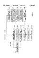
- FIG. 6is a flowchart of methods of making a three dimensional electroluminescent display of FIG. 1 according to the present invention.
- a three dimensional electroluminescent display 10is illustrated in operational relationship with an instrument panel 12 of an occupant compartment 14 of an automotive vehicle.
- the three dimensional electroluminescent display 10provides a luminous display on the instrument panel 12 in the occupant compartment 14.
- the three dimensional electroluminescent display 10includes an applique or sheet 16 which is transparent.
- the sheet 16is a clear film of a plastic material such as polycarbonate.
- the sheet 16is preformed such that it may have a curved outer surface 17a with rounded corners 17b and an aperture 17c extending therethrough to receive a switch (not shown). It should be appreciated that the sheet 16 may be planar and formed subsequently as will be described.
- the three dimensional electroluminescent display 10also includes a first or translucent layer 18 disposed on one side of the sheet 16 to form graphics 19 such as "123".
- the translucent layer 18is printed onto the sheet 16 by suitable means such as silkscreening, offset lithography, screen printing, rotary letter pressing, gravure printing or flexography which are all conventional and known in the art.
- the translucent layer 18may be a multiple colored semi-transparent artwork.
- the translucent layer 18has a first ink silkscreened onto the sheet 16 to configure the graphics 19 with "123”.
- a second inkmay be silkscreened on the other side of the sheet 16 to form opaque graphics 19.
- the translucent layer 18is printed to form windows configuring the graphics 19. It should also be appreciated that the translucent layer 18 may be placed on either side or both sides of the sheet 16.
- the three dimensional electroluminescent display 10may include a second or protective layer 20 placed over the translucent layer 18.
- the protective layer 20is a topcoat of a clear, hard resin such as polyurethane or acrylate polyurethanes.
- the protective layer 20is printed over the translucent layer 18 by suitable means such as silkscreening or spraying as previously described. It should be appreciated that the protective layer 20 protects the translucent layer 18 from abrasions.
- the three dimensional electroluminescent display 10includes at least one EL lamp 22 disposed directly behind or in intimate contact with the sheet 16 or, alternatively, behind the translucent layer 18.
- the EL lamp 22is disposed behind the graphics 19 and secured to the sheet 16 by suitable means such as adhesives or laminates, e.g., pressure sensitive or chemically bonded adhesion promoters or deposited directly onto the sheet 16.
- suitable meanssuch as adhesives or laminates, e.g., pressure sensitive or chemically bonded adhesion promoters or deposited directly onto the sheet 16.
- the EL lamp 22is pre-formed prior to attachment to the sheet 16. It should be appreciated that the EL lamp 22 may be planar and formed subsequently as will be described. It should also be appreciated that the EL lamp 22 emits photons of visible light when a voltage is applied.
- the three dimensional electroluminescent display 10also includes a plurality of conductive leads 24 which are connected to the EL lamp 22.
- the conductive leads 24are made from a conductive material such as copper and may be produced with a stamping die and process as is known in the art. Alternatively, the conductive leads 24 may be screened conductive ink tracings leading from the connector positive/negative leads extending to each EL lamp 22. It should be appreciated that a plurality of EL lamps 22 may be used to allow selective addressing of several EL lamps 22 using conductive leads 24 as described above which allows EL lamps in sharp corners.
- the three dimensional electroluminescent display 10further includes a substrate 26 to provide a three dimensional shape for the sheet 16.
- the substrate 26is a plastic material.
- the sheet 16 with the EL lamp 22may be formed (if not preformed) by conventional methods and inserted into a mold (not shown) in an injection molding machine (not shown) to inject the plastic material into the mold behind the sheet 16 and form the substrate 26 to which the EL lamp 22 adheres.
- the conductive leads 24 and sheet 16 with the EL lamp 22may be inserted into the mold and the plastic material injected into the mold to form the substrate 26 and bind the conductive leads 24, EL lamp 22 and sheet 16 together.
- the molded substrate 26has openings 28 for connection to a standard connector (not shown) with spring loaded pins (not shown) that are disposed in the openings 28 for connection to an electrical current source (not shown).
- the electrical current sourceis an inverter within the automotive vehicle.
- the substrate 28may also have projections 30a and 30b for connection to the instrument panel 12. It should be appreciated that the EL lamp 22 and substrate 26 are bonded together into an integral unit and the EL lamp 22 conforms to the three dimensional shape of the substrate 26.
- the electrical current sourceprovides voltage through the conductive leads 24 and to the EL lamp 22.
- the electric fieldexcites the phosphors of the EL lamp 22 and photons are emitted with almost all of the radiant energy lying within the visible light spectrum.
- the visible lightpasses through the graphics 19 to make the "123" luminous in the occupant compartment 14.
- the layers of the EL lamp 22may be screen printed onto the second surface of the translucent layer 18 or sheet 16, or the translucent layer 18 may be printed on the front electrode of the EL lamp 22 such as by silk-screening.
- the conductive leads 24may be printed on the EL lamp 22 such as by silk-screening. It should be appreciated that the graphics 19 are produced prior to molding by patterning an electrode of the EL lamp 22, by screen printing onto a front or first surface of the EL lamp 22, or by screen printing onto a separate sheet 16.
- the three dimensional electroluminescent display 10is made by a method according to the present invention.
- the methodincludes the steps of providing the sheet 16 of a transparent material and placing the translucent layer 18 on at least one side of the sheet 16.
- the methodfurther includes the steps of placing at least one EL lamp 22 adjacent the translucent layer 18 and molding the substrate 26 to the EL lamp 22 and the sheet 16 and forming the integral, three dimensional display 10.
- the first methodincludes providing the sheet 16 and printing the translucent layer 18 having graphics 19 on the sheet 16 in box 40 and pre-forming the sheet 16 in box 42.
- the first methodalso includes attaching or securing at least one EL lamp 22 to the sheet 16 in box 44.
- the EL lamp 22may be pre-formed prior to attachment to the sheet 16.
- box 42is optional and the sheet 16 and EL lamp 22 formed after box 44.
- the first methodincludes putting or placing the sheet 16 with the EL lamp 22 into the mold in box 48, molding the substrate 26 to the EL lamp 22 and sheet 16 in box 50, and removing the three dimensional electroluminescent display 10 from the mold in box 52.
- a second methodincludes providing the sheet 16 and printing the translucent layer 18 having graphics 19 on the sheet 16 in box 54.
- the second methodincludes depositing (patterned) transparent electrode of at least one EL lamp 22 on the sheet 16 in box 56, depositing (patterned) layer of phosphor of the EL lamp 22 on the sheet 16 in box 58, and depositing (patterned) rear electrode of the EL lamp 22 on the sheet 16 in box 60.
- the second methodincludes pre-forming the sheet 16 with at least one EL lamp 22 in box 62 and performs the steps in boxes 48, 50 and 52 previously described.
- the present inventionprovides a luminous three dimensional display 10 having maximum brightness and uniformity.
- the three dimensional electroluminescent display 10provides even contact of the EL lamp 22 against the sheet 16.
- the three dimensional electroluminescent display 10also provides a substrate 26 which is molded to the EL lamp 22 and sheet 16 and protects the EL lamp 22 from mechanical damage and simplifies assembly.
- the three dimensional electroluminescent display 10may provide graphics 19 at different levels and the intimate contact between the EL lamp 22 and graphics 19 provides uniform luminosity.
- the three dimensional electroluminescent display 10can be used for decorative lighting or with graphics, for providing useful or necessary information to a viewer. Several colors can be combined in a single display and portions of a display can be selectively activated to further enhance the effectiveness of the display.
- the three dimensional electroluminescent display 10may be used in the instrument panel 12 of an automotive vehicle and provide immunity to shock and longer service life of the EL lamp 22 in the vehicle as compared to conventional incandescent lamps.
Landscapes
- Physics & Mathematics (AREA)
- General Physics & Mathematics (AREA)
- Engineering & Computer Science (AREA)
- Theoretical Computer Science (AREA)
- Illuminated Signs And Luminous Advertising (AREA)
- Electroluminescent Light Sources (AREA)
- Devices For Indicating Variable Information By Combining Individual Elements (AREA)
Abstract
Description
Claims (14)
Priority Applications (5)
| Application Number | Priority Date | Filing Date | Title |
|---|---|---|---|
| US08/164,142US5780965A (en) | 1993-12-09 | 1993-12-09 | Three dimensional electroluminescent display |
| GB9416762AGB2284699B (en) | 1993-12-09 | 1994-08-18 | Three dimensional electroluminescent display |
| DE4430907ADE4430907B4 (en) | 1993-12-09 | 1994-08-31 | Three-dimensionally shaped electroluminescent display and method for its production |
| JP6217106AJPH07199842A (en) | 1993-12-09 | 1994-09-12 | Three-dimensional electroluminescence display device |
| JP1998009412UJP3068349U (en) | 1993-12-09 | 1998-11-30 | Three-dimensional electroluminescence display device |
Applications Claiming Priority (1)
| Application Number | Priority Date | Filing Date | Title |
|---|---|---|---|
| US08/164,142US5780965A (en) | 1993-12-09 | 1993-12-09 | Three dimensional electroluminescent display |
Publications (1)
| Publication Number | Publication Date |
|---|---|
| US5780965Atrue US5780965A (en) | 1998-07-14 |
Family
ID=22593158
Family Applications (1)
| Application Number | Title | Priority Date | Filing Date |
|---|---|---|---|
| US08/164,142Expired - LifetimeUS5780965A (en) | 1993-12-09 | 1993-12-09 | Three dimensional electroluminescent display |
Country Status (4)
| Country | Link |
|---|---|
| US (1) | US5780965A (en) |
| JP (2) | JPH07199842A (en) |
| DE (1) | DE4430907B4 (en) |
| GB (1) | GB2284699B (en) |
Cited By (49)
| Publication number | Priority date | Publication date | Assignee | Title |
|---|---|---|---|---|
| US6281788B1 (en)* | 1999-09-13 | 2001-08-28 | Mannesmann Vdo Ag | Indicating instrument |
| WO2001084584A1 (en)* | 2000-05-01 | 2001-11-08 | Durel Corporation | Electroluminescent lamp devices and their manufacture |
| US6411029B1 (en) | 1997-04-26 | 2002-06-25 | Schonberg + Cerny Gmbh | Plastic shaped body with an integrated optoelectronic luminous element |
| US20030075826A1 (en)* | 2001-10-22 | 2003-04-24 | Atsushi Saito | Manufacturing method of EL insert molding |
| WO2003037039A1 (en)* | 2001-10-24 | 2003-05-01 | Lumitec Ag | Three-dimensional electroluminescence display |
| EP1289233A3 (en)* | 2001-08-29 | 2003-08-20 | Nokia Corporation | Illuminated cover for an electronic device including an electroluminescent foil and manufacturing method |
| US6621212B1 (en) | 1999-12-20 | 2003-09-16 | Morgan Adhesives Company | Electroluminescent lamp structure |
| US6624569B1 (en) | 1999-12-20 | 2003-09-23 | Morgan Adhesives Company | Electroluminescent labels |
| US6639355B1 (en) | 1999-12-20 | 2003-10-28 | Morgan Adhesives Company | Multidirectional electroluminescent lamp structures |
| US20040012339A1 (en)* | 2002-07-19 | 2004-01-22 | Grant Gary M. | Illuminated graphics system |
| US20050067952A1 (en)* | 2003-09-29 | 2005-03-31 | Durel Corporation | Flexible, molded EL lamp |
| US6922020B2 (en) | 2002-06-19 | 2005-07-26 | Morgan Adhesives Company | Electroluminescent lamp module and processing method |
| US20050194895A1 (en)* | 2004-03-02 | 2005-09-08 | World Properties, Inc. | Dimensionally stable electroluminescent lamp without substrate |
| US6942916B2 (en) | 2001-01-11 | 2005-09-13 | Hewlett-Packard Development Company, L.P. | Inkjet printable electroluminescent media |
| US20050242703A1 (en)* | 2004-04-29 | 2005-11-03 | World Properties, Inc. | Variable thickness EL lamp |
| US20050246928A1 (en)* | 2004-04-19 | 2005-11-10 | Joy World, Inc. | Illuminating display |
| US20060012216A1 (en)* | 2004-07-15 | 2006-01-19 | Bogdan Radu | Automotive ashtray and method for making the same |
| US20060012205A1 (en)* | 2004-07-15 | 2006-01-19 | Bogdan Radu | Automotive storage compartment and method for making the same |
| US20060022591A1 (en)* | 2004-07-28 | 2006-02-02 | Bayer Materialscience Ag | Light-emitting, transparent film system based on polymers, and process for its production |
| US20060054482A1 (en)* | 2004-09-15 | 2006-03-16 | Bodgan Radu | Flip pack switch assembly with electroluminescent lamp and injection molding method of making same |
| US20060060415A1 (en)* | 2004-09-20 | 2006-03-23 | Bogdan Radu | Door trim speaker grille with electroluminescent lamp and injection molding method of making same |
| US20060061138A1 (en)* | 2004-09-20 | 2006-03-23 | Bogdan Radu | Door trim bolster with electroluminescent lamp and injection moldilng method of making same |
| US20060062006A1 (en)* | 2004-09-21 | 2006-03-23 | Bodgan Radu | Automotive storage compartment having an electroluminescent lamp and method of making the same |
| US7017968B1 (en) | 2004-09-29 | 2006-03-28 | Lear Corporation | Automotive ashtray having an electroluminescent lamp and method of making the same |
| US20060067083A1 (en)* | 2004-09-29 | 2006-03-30 | Radu Bogdan | Automotive map pocket having an electroluminescent lamp and method of making the same |
| US20060273983A1 (en)* | 2005-06-01 | 2006-12-07 | Samsung Electronics Co., Ltd. | Volumetric three-dimentional display panel and system using multi-layered organic light emitting devices |
| US20080080204A1 (en)* | 2006-06-23 | 2008-04-03 | Faurecia Interior Systems U.S.A., Inc. | Molded panel and method of manufacture |
| EP1466461A4 (en)* | 2002-01-07 | 2008-05-14 | Nokia Corp | LIGHT ENVELOPES |
| WO2008055978A1 (en)* | 2006-11-10 | 2008-05-15 | Leopold Kostal Gmbh & Co. Kg | Operating unit for a motor vehicle with “black-panel” effect |
| WO2009070257A1 (en)* | 2007-11-30 | 2009-06-04 | World Properties, Inc. | Isolation mask for fine line display |
| US20090236984A1 (en)* | 2006-07-01 | 2009-09-24 | Lyttron Technology Gmbh | 3D Electroluminescent High-Pressure Forming Element, Production Process And Application |
| CN1701640B (en)* | 2001-10-24 | 2010-05-12 | 拜尔瑞士股份公司 | 3D Electroluminescent Display |
| US20100232171A1 (en)* | 2009-03-10 | 2010-09-16 | International Automotive Components Group North America, Inc. | Integration Of Light Emitting Devices And Printed Electronics Into Vehicle Trim Components |
| US20110101873A1 (en)* | 2009-11-03 | 2011-05-05 | Jessica Wang | Lighting display having animated effect |
| US20110205154A1 (en)* | 2010-02-25 | 2011-08-25 | Research In Motion Limited | Illuminated optical navigation module |
| US20110205179A1 (en)* | 2010-02-25 | 2011-08-25 | Research In Motion Limited | Three-dimensional illuminated area for optical navigation |
| CN101207949B (en)* | 2006-12-22 | 2012-05-23 | 东洋电装株式会社 | Light-emitting device |
| US20120294016A1 (en)* | 2011-05-16 | 2012-11-22 | Michael Trung Tran | Loadable cassette for operatively holding a planar light source |
| US8470388B1 (en) | 2012-01-03 | 2013-06-25 | Andrew Zsinko | Electroluminescent devices and their manufacture |
| CN101632326B (en)* | 2006-12-07 | 2014-06-25 | 拜尔材料科学股份公司 | Electroluminescent element comprising translucent metal foil, method of manufacture and application thereof |
| US8982063B2 (en) | 2010-02-25 | 2015-03-17 | Blackberry Limited | Optical naviagation module having a metallic illumination ring |
| US9642212B1 (en) | 2015-06-11 | 2017-05-02 | Darkside Scientific, Llc | Electroluminescent system and process |
| US10434846B2 (en) | 2015-09-07 | 2019-10-08 | Sabic Global Technologies B.V. | Surfaces of plastic glazing of tailgates |
| US10562446B2 (en) | 2015-03-23 | 2020-02-18 | International Automotive Components Group Gmbh | Interior trim element for a motor vehicle |
| US10597097B2 (en) | 2015-09-07 | 2020-03-24 | Sabic Global Technologies B.V. | Aerodynamic features of plastic glazing of tailgates |
| US10690314B2 (en) | 2015-09-07 | 2020-06-23 | Sabic Global Technologies B.V. | Lighting systems of tailgates with plastic glazing |
| US11267173B2 (en) | 2015-09-07 | 2022-03-08 | Sabic Global Technologies B.V. | Molding of plastic glazing of tailgates |
| US11466834B2 (en) | 2015-11-23 | 2022-10-11 | Sabic Global Technologies B.V. | Lighting systems for windows having plastic glazing |
| US11533793B2 (en) | 2016-07-28 | 2022-12-20 | Darkside Scientific, Inc. | Electroluminescent system and process |
Families Citing this family (20)
| Publication number | Priority date | Publication date | Assignee | Title |
|---|---|---|---|---|
| DE19715658A1 (en) | 1997-04-16 | 1998-10-22 | Philips Leiterplatten At Gmbh | Multifunction circuit board with opto-electronically active component |
| DE29820304U1 (en)* | 1998-11-12 | 1999-01-07 | TRW Automotive Safety Systems GmbH, 63743 Aschaffenburg | Motor vehicle emblem |
| DE19859195C2 (en)* | 1998-12-21 | 2001-02-22 | Holzindustrie Bruchsal Gmbh | Visible installation part made of composite material |
| CN1191173C (en)* | 2001-07-16 | 2005-03-02 | 太乙印刷企业股份有限公司 | A method of lithographic screen printing applied to IMD hot pressing and injection molding |
| JP2003163083A (en)* | 2001-09-13 | 2003-06-06 | Nissha Printing Co Ltd | El emission decorative mold, manufacturing method therefor, and el emission decorative sheet |
| WO2003025890A1 (en)* | 2001-09-13 | 2003-03-27 | Nissha Printing Co.,Ltd. | El luminous decorative molding and production method therefor, el luminous decorative sheet |
| JP2003092189A (en)* | 2001-09-18 | 2003-03-28 | Seiko Precision Inc | Light emitting device with EL |
| DE102006037998A1 (en)* | 2006-08-14 | 2008-02-21 | Schreiner Group Gmbh & Co. Kg | Method for producing a three-dimensional component |
| DE102006059203A1 (en)* | 2006-12-13 | 2008-06-19 | Lyttron Technology Gmbh | Bendable 3D EL-HDFV element and manufacturing process and application |
| DE102007058272A1 (en)* | 2007-12-04 | 2009-06-18 | Audi Ag | Lining element for use in interior of motor vehicle, has light source i.e. LED, connected with inner layer to inject light into inner layer, and decorative element with partial translucence arranged between outer and inner layers |
| DE102007061326B4 (en) | 2007-12-19 | 2022-02-03 | Dr. Ing. H.C. F. Porsche Aktiengesellschaft | Functional panel with illuminated symbols |
| US20120051067A1 (en)* | 2010-08-24 | 2012-03-01 | Key Plastics L.L.C. | Lighting display and method of manufacturing same |
| DE102010061963A1 (en) | 2010-11-25 | 2012-05-31 | Bayer Materialscience Aktiengesellschaft | EL elements containing a pigment layer with crosslinking systems with blocked isocyanate groups |
| KR102444269B1 (en) | 2013-09-27 | 2022-09-16 | 택토텍 오와이 | A method for manufacturing the structure of an electric machine and an arrangement for carrying out the method |
| DE102013223247A1 (en)* | 2013-11-14 | 2015-05-21 | Zf Friedrichshafen Ag | A display device for a vehicle, a shifting device for shifting a vehicle transmission, and a method of manufacturing a display device for a vehicle |
| GB2521000A (en) | 2013-12-07 | 2015-06-10 | Ct De Inova Μes Csem Brasil | Electroluminescent device and manufacturing method thereof |
| DE102014206034A1 (en)* | 2014-03-31 | 2015-10-01 | Magna Interiors Management Gmbh | Component made of transparent film and production thereof |
| US9500791B2 (en)* | 2014-09-22 | 2016-11-22 | Visteon Global Technolgoies, Inc. | Gradient light halo for a remote input device |
| DE102014220348A1 (en)* | 2014-10-08 | 2016-04-14 | Continental Automotive Gmbh | display |
| DE102015201261A1 (en)* | 2015-01-26 | 2016-07-28 | Johnson Controls Interiors Management Gmbh | INDOOR EQUIPMENT FOR VEHICLES AND A METHOD FOR MANUFACTURING SUCH A INTERIOR EQUIPMENT PART |
Citations (32)
| Publication number | Priority date | Publication date | Assignee | Title |
|---|---|---|---|---|
| US2867739A (en)* | 1956-01-05 | 1959-01-06 | Hyman A Michlin | Electroluminescent color lamp |
| US2975318A (en)* | 1958-06-23 | 1961-03-14 | Rca Corp | Electroluminescent devices |
| US3182415A (en)* | 1962-11-09 | 1965-05-11 | Lockheed Aircraft Corp | Electroluminescent display panels |
| US3670067A (en)* | 1968-01-02 | 1972-06-13 | Ato Inc | Method of making illuminated panel |
| US3680239A (en)* | 1970-07-14 | 1972-08-01 | Willard H Andrews | Picture frame attachment |
| US3680237A (en)* | 1971-04-30 | 1972-08-01 | John Gerard Finnerty Sr | Outdoor illuminated signs |
| GB1365333A (en)* | 1970-12-05 | 1974-08-29 | Samantha Srl | Electroluminescent number plate for motor vehicles |
| US4138620A (en)* | 1978-03-24 | 1979-02-06 | Minnesota Mining And Manufacturing Company | Multi-panel electroluminescent light assembly |
| US4195431A (en)* | 1977-12-12 | 1980-04-01 | Neufeld Eugene S | Graphic displays employing electroluminescent panels |
| US4208869A (en)* | 1976-07-31 | 1980-06-24 | Citizen Watch Co., Ltd. | Illumination device for electronic timepiece |
| US4275403A (en)* | 1970-02-06 | 1981-06-23 | U.S. Philips Corporation | Electro-luminescent semiconductor device |
| US4457089A (en)* | 1981-10-02 | 1984-07-03 | Phillips Jr Wilbert H | Decorative, illuminated automotive reflector |
| US4494326A (en)* | 1981-09-29 | 1985-01-22 | Nissan Motor Company, Limited | Electrolumiscent display structure for motor vehicle window |
| US4578617A (en)* | 1983-11-07 | 1986-03-25 | Astronics Corporation | Electroluminescent panels |
| US4593228A (en)* | 1984-05-15 | 1986-06-03 | Albrechtson Loren R | Laminated electroluminescent lamp structure and method of manufacturing |
| US4603065A (en)* | 1984-02-10 | 1986-07-29 | Toyoda Gosei Co., Ltd. | Decorative part |
| US4645970A (en)* | 1984-11-05 | 1987-02-24 | Donnelly Corporation | Illuminated EL panel assembly |
| US4721883A (en)* | 1986-06-02 | 1988-01-26 | Sidney Jacobs | Electroluminescent display and method of making same |
| US4788629A (en)* | 1986-10-29 | 1988-11-29 | Loctite Luminescent Systems, Inc. | Instrument panel members |
| GB2217527A (en)* | 1988-02-03 | 1989-10-25 | Mcgavigan John & Co Ltd | Electrical connection strip |
| EP0368450A2 (en)* | 1988-09-08 | 1990-05-16 | JOHN MCGAVIGAN & COMPANY LIMITED | Data display devices |
| GB2230638A (en)* | 1989-04-17 | 1990-10-24 | Kaumagraph Electroluminescent | Colour displays |
| GB2233139A (en)* | 1989-06-12 | 1991-01-02 | Specialist Printers Ltd | Electroluminescent device |
| US5005306A (en)* | 1989-06-21 | 1991-04-09 | Kinstler William G | Illuminated vehicle sign |
| US5051654A (en)* | 1988-12-16 | 1991-09-24 | Loctite Luminescent Systems, Inc. | Electroluminescent lamp and method of manufacture |
| US5068157A (en)* | 1988-10-26 | 1991-11-26 | Samsung Electron Devices Co., Ltd. | Electroluminescent element |
| US5107175A (en)* | 1989-06-27 | 1992-04-21 | Sumitomo Bakelite Company Limited | Moisture trapping film for el lamps of the organic dispersion type |
| US5116270A (en)* | 1989-11-21 | 1992-05-26 | Seikosha Co., Ltd. | Luminous pointer and manufacturing method thereof |
| US5122709A (en)* | 1989-03-20 | 1992-06-16 | Hitachi, Ltd. | Antistatic cathode ray tube with lobe like projections and high gloss and hardness |
| US5131877A (en)* | 1989-10-12 | 1992-07-21 | Alps Electric Co., Ltd. | Electroluminescent device |
| US5184969A (en)* | 1988-05-31 | 1993-02-09 | Electroluminscent Technologies Corporation | Electroluminescent lamp and method for producing the same |
| US5317488A (en)* | 1992-11-17 | 1994-05-31 | Darlene Penrod | Insulated integral electroluminescent lighting system |
Family Cites Families (4)
| Publication number | Priority date | Publication date | Assignee | Title |
|---|---|---|---|---|
| DE2555312A1 (en)* | 1975-12-09 | 1977-06-23 | Licentia Gmbh | Optical display unit for CRT - has auxiliary films of electro-conducting, electro-luminescent and photo-dielectric materials |
| US4104555A (en)* | 1977-01-27 | 1978-08-01 | Atkins & Merrill, Inc. | High temperature encapsulated electroluminescent lamp |
| JPH0547470A (en)* | 1991-08-20 | 1993-02-26 | Matsushita Electric Ind Co Ltd | Dispersion type EL and manufacturing method thereof |
| JPH0572984A (en)* | 1991-09-11 | 1993-03-26 | Noda Denshi Kogyo Kk | Light emitting display body |
- 1993
- 1993-12-09USUS08/164,142patent/US5780965A/ennot_activeExpired - Lifetime
- 1994
- 1994-08-18GBGB9416762Apatent/GB2284699B/ennot_activeExpired - Fee Related
- 1994-08-31DEDE4430907Apatent/DE4430907B4/ennot_activeExpired - Fee Related
- 1994-09-12JPJP6217106Apatent/JPH07199842A/enactivePending
- 1998
- 1998-11-30JPJP1998009412Upatent/JP3068349U/ennot_activeExpired - Lifetime
Patent Citations (32)
| Publication number | Priority date | Publication date | Assignee | Title |
|---|---|---|---|---|
| US2867739A (en)* | 1956-01-05 | 1959-01-06 | Hyman A Michlin | Electroluminescent color lamp |
| US2975318A (en)* | 1958-06-23 | 1961-03-14 | Rca Corp | Electroluminescent devices |
| US3182415A (en)* | 1962-11-09 | 1965-05-11 | Lockheed Aircraft Corp | Electroluminescent display panels |
| US3670067A (en)* | 1968-01-02 | 1972-06-13 | Ato Inc | Method of making illuminated panel |
| US4275403A (en)* | 1970-02-06 | 1981-06-23 | U.S. Philips Corporation | Electro-luminescent semiconductor device |
| US3680239A (en)* | 1970-07-14 | 1972-08-01 | Willard H Andrews | Picture frame attachment |
| GB1365333A (en)* | 1970-12-05 | 1974-08-29 | Samantha Srl | Electroluminescent number plate for motor vehicles |
| US3680237A (en)* | 1971-04-30 | 1972-08-01 | John Gerard Finnerty Sr | Outdoor illuminated signs |
| US4208869A (en)* | 1976-07-31 | 1980-06-24 | Citizen Watch Co., Ltd. | Illumination device for electronic timepiece |
| US4195431A (en)* | 1977-12-12 | 1980-04-01 | Neufeld Eugene S | Graphic displays employing electroluminescent panels |
| US4138620A (en)* | 1978-03-24 | 1979-02-06 | Minnesota Mining And Manufacturing Company | Multi-panel electroluminescent light assembly |
| US4494326A (en)* | 1981-09-29 | 1985-01-22 | Nissan Motor Company, Limited | Electrolumiscent display structure for motor vehicle window |
| US4457089A (en)* | 1981-10-02 | 1984-07-03 | Phillips Jr Wilbert H | Decorative, illuminated automotive reflector |
| US4578617A (en)* | 1983-11-07 | 1986-03-25 | Astronics Corporation | Electroluminescent panels |
| US4603065A (en)* | 1984-02-10 | 1986-07-29 | Toyoda Gosei Co., Ltd. | Decorative part |
| US4593228A (en)* | 1984-05-15 | 1986-06-03 | Albrechtson Loren R | Laminated electroluminescent lamp structure and method of manufacturing |
| US4645970A (en)* | 1984-11-05 | 1987-02-24 | Donnelly Corporation | Illuminated EL panel assembly |
| US4721883A (en)* | 1986-06-02 | 1988-01-26 | Sidney Jacobs | Electroluminescent display and method of making same |
| US4788629A (en)* | 1986-10-29 | 1988-11-29 | Loctite Luminescent Systems, Inc. | Instrument panel members |
| GB2217527A (en)* | 1988-02-03 | 1989-10-25 | Mcgavigan John & Co Ltd | Electrical connection strip |
| US5184969A (en)* | 1988-05-31 | 1993-02-09 | Electroluminscent Technologies Corporation | Electroluminescent lamp and method for producing the same |
| EP0368450A2 (en)* | 1988-09-08 | 1990-05-16 | JOHN MCGAVIGAN & COMPANY LIMITED | Data display devices |
| US5068157A (en)* | 1988-10-26 | 1991-11-26 | Samsung Electron Devices Co., Ltd. | Electroluminescent element |
| US5051654A (en)* | 1988-12-16 | 1991-09-24 | Loctite Luminescent Systems, Inc. | Electroluminescent lamp and method of manufacture |
| US5122709A (en)* | 1989-03-20 | 1992-06-16 | Hitachi, Ltd. | Antistatic cathode ray tube with lobe like projections and high gloss and hardness |
| GB2230638A (en)* | 1989-04-17 | 1990-10-24 | Kaumagraph Electroluminescent | Colour displays |
| GB2233139A (en)* | 1989-06-12 | 1991-01-02 | Specialist Printers Ltd | Electroluminescent device |
| US5005306A (en)* | 1989-06-21 | 1991-04-09 | Kinstler William G | Illuminated vehicle sign |
| US5107175A (en)* | 1989-06-27 | 1992-04-21 | Sumitomo Bakelite Company Limited | Moisture trapping film for el lamps of the organic dispersion type |
| US5131877A (en)* | 1989-10-12 | 1992-07-21 | Alps Electric Co., Ltd. | Electroluminescent device |
| US5116270A (en)* | 1989-11-21 | 1992-05-26 | Seikosha Co., Ltd. | Luminous pointer and manufacturing method thereof |
| US5317488A (en)* | 1992-11-17 | 1994-05-31 | Darlene Penrod | Insulated integral electroluminescent lighting system |
Cited By (82)
| Publication number | Priority date | Publication date | Assignee | Title |
|---|---|---|---|---|
| US6465951B1 (en)* | 1992-12-16 | 2002-10-15 | Durel Corporation | Electroluminescent lamp devices and their manufacture |
| US6411029B1 (en) | 1997-04-26 | 2002-06-25 | Schonberg + Cerny Gmbh | Plastic shaped body with an integrated optoelectronic luminous element |
| US6281788B1 (en)* | 1999-09-13 | 2001-08-28 | Mannesmann Vdo Ag | Indicating instrument |
| US6621212B1 (en) | 1999-12-20 | 2003-09-16 | Morgan Adhesives Company | Electroluminescent lamp structure |
| US6639355B1 (en) | 1999-12-20 | 2003-10-28 | Morgan Adhesives Company | Multidirectional electroluminescent lamp structures |
| US6624569B1 (en) | 1999-12-20 | 2003-09-23 | Morgan Adhesives Company | Electroluminescent labels |
| WO2001084584A1 (en)* | 2000-05-01 | 2001-11-08 | Durel Corporation | Electroluminescent lamp devices and their manufacture |
| US6942916B2 (en) | 2001-01-11 | 2005-09-13 | Hewlett-Packard Development Company, L.P. | Inkjet printable electroluminescent media |
| US6773644B1 (en)* | 2001-08-29 | 2004-08-10 | Nokia Corporation | Method of making illuminated covers |
| EP1289233A3 (en)* | 2001-08-29 | 2003-08-20 | Nokia Corporation | Illuminated cover for an electronic device including an electroluminescent foil and manufacturing method |
| US6790396B2 (en) | 2001-08-29 | 2004-09-14 | Nokia Corporation | Method of making illuminated covers |
| US20030075826A1 (en)* | 2001-10-22 | 2003-04-24 | Atsushi Saito | Manufacturing method of EL insert molding |
| EA007665B1 (en)* | 2001-10-24 | 2006-12-29 | Лумитек Аг | Three-dimensional electroluminescence display |
| US20050040769A1 (en)* | 2001-10-24 | 2005-02-24 | Emil Enz | Three-dimensional electroluminescence display |
| CN1701640B (en)* | 2001-10-24 | 2010-05-12 | 拜尔瑞士股份公司 | 3D Electroluminescent Display |
| WO2003037039A1 (en)* | 2001-10-24 | 2003-05-01 | Lumitec Ag | Three-dimensional electroluminescence display |
| US7439672B2 (en) | 2001-10-24 | 2008-10-21 | Lyttron Technology Gmgh | Three-dimensional electroluminescence display |
| EP2178342A1 (en)* | 2001-10-24 | 2010-04-21 | Bayer MaterialScience AG | Three-Dimensional Electroluminescence Display |
| EP1466461A4 (en)* | 2002-01-07 | 2008-05-14 | Nokia Corp | LIGHT ENVELOPES |
| US6922020B2 (en) | 2002-06-19 | 2005-07-26 | Morgan Adhesives Company | Electroluminescent lamp module and processing method |
| US6759809B2 (en)* | 2002-07-19 | 2004-07-06 | Gary M. Grant | Illuminated graphics system |
| US20040012339A1 (en)* | 2002-07-19 | 2004-01-22 | Grant Gary M. | Illuminated graphics system |
| US20050067952A1 (en)* | 2003-09-29 | 2005-03-31 | Durel Corporation | Flexible, molded EL lamp |
| US20050194895A1 (en)* | 2004-03-02 | 2005-09-08 | World Properties, Inc. | Dimensionally stable electroluminescent lamp without substrate |
| US7202600B2 (en) | 2004-03-02 | 2007-04-10 | World Properties, Inc. | Dimensionally stable electroluminescent lamp without substrate |
| US20050246928A1 (en)* | 2004-04-19 | 2005-11-10 | Joy World, Inc. | Illuminating display |
| US7294966B2 (en)* | 2004-04-29 | 2007-11-13 | World Properties, Inc. | Variable thickness EL lamp |
| US20050242703A1 (en)* | 2004-04-29 | 2005-11-03 | World Properties, Inc. | Variable thickness EL lamp |
| WO2005112065A3 (en)* | 2004-04-29 | 2006-12-21 | World Properties Inc | Variable thickness el lamp |
| US20060012216A1 (en)* | 2004-07-15 | 2006-01-19 | Bogdan Radu | Automotive ashtray and method for making the same |
| US20060012205A1 (en)* | 2004-07-15 | 2006-01-19 | Bogdan Radu | Automotive storage compartment and method for making the same |
| US7032954B2 (en) | 2004-07-15 | 2006-04-25 | Lear Corporation | Automotive ashtray and method for making the same |
| US7456569B2 (en) | 2004-07-28 | 2008-11-25 | Lyttron Technology Gmbh | Light-emitting, transparent film system based on polymers |
| US20060022591A1 (en)* | 2004-07-28 | 2006-02-02 | Bayer Materialscience Ag | Light-emitting, transparent film system based on polymers, and process for its production |
| US7265306B2 (en) | 2004-09-15 | 2007-09-04 | Bodgan Radu | Flip pack switch assembly with electroluminescent lamp and injection molding method of making same |
| US20060054482A1 (en)* | 2004-09-15 | 2006-03-16 | Bodgan Radu | Flip pack switch assembly with electroluminescent lamp and injection molding method of making same |
| US7299892B2 (en) | 2004-09-20 | 2007-11-27 | International Automotive Components Group North America, Inc. | Door trim speaker grille with electroluminescent lamp and injection molding method of making same |
| US7237933B2 (en) | 2004-09-20 | 2007-07-03 | Lear Corporation | Door trim bolster with electroluminescent lamp and injection molding method of making same |
| US20060060415A1 (en)* | 2004-09-20 | 2006-03-23 | Bogdan Radu | Door trim speaker grille with electroluminescent lamp and injection molding method of making same |
| US20060061138A1 (en)* | 2004-09-20 | 2006-03-23 | Bogdan Radu | Door trim bolster with electroluminescent lamp and injection moldilng method of making same |
| US20060062006A1 (en)* | 2004-09-21 | 2006-03-23 | Bodgan Radu | Automotive storage compartment having an electroluminescent lamp and method of making the same |
| US7287885B2 (en) | 2004-09-21 | 2007-10-30 | International Automotive Components Group, Llc | Automotive storage compartment having an electroluminescent lamp and method of making the same |
| US20060066119A1 (en)* | 2004-09-29 | 2006-03-30 | Bogdan Radu | Automotive ashtray having an electroluminescent lamp and method of making the same |
| US20060067083A1 (en)* | 2004-09-29 | 2006-03-30 | Radu Bogdan | Automotive map pocket having an electroluminescent lamp and method of making the same |
| US7150550B2 (en) | 2004-09-29 | 2006-12-19 | Lear Corporation | Automotive map pocket having an electroluminescent lamp and method of making the same |
| US7017968B1 (en) | 2004-09-29 | 2006-03-28 | Lear Corporation | Automotive ashtray having an electroluminescent lamp and method of making the same |
| US8253652B2 (en) | 2005-06-01 | 2012-08-28 | Samsung Electronics Co., Ltd. | Volumetric three-dimensional display panel and system using multi-layered organic light emitting devices |
| US20060273983A1 (en)* | 2005-06-01 | 2006-12-07 | Samsung Electronics Co., Ltd. | Volumetric three-dimentional display panel and system using multi-layered organic light emitting devices |
| US20080080204A1 (en)* | 2006-06-23 | 2008-04-03 | Faurecia Interior Systems U.S.A., Inc. | Molded panel and method of manufacture |
| US20090236984A1 (en)* | 2006-07-01 | 2009-09-24 | Lyttron Technology Gmbh | 3D Electroluminescent High-Pressure Forming Element, Production Process And Application |
| WO2008055978A1 (en)* | 2006-11-10 | 2008-05-15 | Leopold Kostal Gmbh & Co. Kg | Operating unit for a motor vehicle with “black-panel” effect |
| CN101632326B (en)* | 2006-12-07 | 2014-06-25 | 拜尔材料科学股份公司 | Electroluminescent element comprising translucent metal foil, method of manufacture and application thereof |
| CN101207949B (en)* | 2006-12-22 | 2012-05-23 | 东洋电装株式会社 | Light-emitting device |
| GB2467288A (en)* | 2007-11-30 | 2010-07-28 | World Properties Inc | Isolation mask for fine line display |
| WO2009070257A1 (en)* | 2007-11-30 | 2009-06-04 | World Properties, Inc. | Isolation mask for fine line display |
| US7862220B2 (en) | 2009-03-10 | 2011-01-04 | International Automotive Components Group North America, Inc | Integration of light emitting devices and printed electronics into vehicle trim components |
| US20100232171A1 (en)* | 2009-03-10 | 2010-09-16 | International Automotive Components Group North America, Inc. | Integration Of Light Emitting Devices And Printed Electronics Into Vehicle Trim Components |
| US20110101873A1 (en)* | 2009-11-03 | 2011-05-05 | Jessica Wang | Lighting display having animated effect |
| US9159253B2 (en)* | 2009-11-03 | 2015-10-13 | Jessica Wang | Lighting display having animated effect |
| US20110205179A1 (en)* | 2010-02-25 | 2011-08-25 | Research In Motion Limited | Three-dimensional illuminated area for optical navigation |
| US20110205154A1 (en)* | 2010-02-25 | 2011-08-25 | Research In Motion Limited | Illuminated optical navigation module |
| US8982063B2 (en) | 2010-02-25 | 2015-03-17 | Blackberry Limited | Optical naviagation module having a metallic illumination ring |
| US8937598B2 (en) | 2010-02-25 | 2015-01-20 | Blackberry Limited | Illuminated optical navigation module |
| US20120294016A1 (en)* | 2011-05-16 | 2012-11-22 | Michael Trung Tran | Loadable cassette for operatively holding a planar light source |
| US9062836B2 (en)* | 2011-05-16 | 2015-06-23 | Abl Ip Holding, Llc | Cassette for receiving a planar light source |
| US8470388B1 (en) | 2012-01-03 | 2013-06-25 | Andrew Zsinko | Electroluminescent devices and their manufacture |
| US10562446B2 (en) | 2015-03-23 | 2020-02-18 | International Automotive Components Group Gmbh | Interior trim element for a motor vehicle |
| US9642212B1 (en) | 2015-06-11 | 2017-05-02 | Darkside Scientific, Llc | Electroluminescent system and process |
| US10948152B2 (en) | 2015-09-07 | 2021-03-16 | Sabic Global Technologies B.V. | Lighting systems of tailgates with plastic glazing |
| US11845240B2 (en) | 2015-09-07 | 2023-12-19 | Sabic Global Technologies B.V. | Three shot plastic tailgate |
| US10690314B2 (en) | 2015-09-07 | 2020-06-23 | Sabic Global Technologies B.V. | Lighting systems of tailgates with plastic glazing |
| US10717348B2 (en) | 2015-09-07 | 2020-07-21 | Sabic Global Technologies B.V. | Surfaces of plastic glazing of tailgates |
| US10434846B2 (en) | 2015-09-07 | 2019-10-08 | Sabic Global Technologies B.V. | Surfaces of plastic glazing of tailgates |
| US11267173B2 (en) | 2015-09-07 | 2022-03-08 | Sabic Global Technologies B.V. | Molding of plastic glazing of tailgates |
| US11458709B2 (en) | 2015-09-07 | 2022-10-04 | Sabic Global Technologies B.V. | Three shot plastic tailgate |
| US12390967B2 (en) | 2015-09-07 | 2025-08-19 | Sabic Global Technologies B.V. | Molding of plastic glazing of tailgates |
| US12330397B2 (en) | 2015-09-07 | 2025-06-17 | Sabic Global Technologies B.V. | Three shot plastic tailgate |
| US10597097B2 (en) | 2015-09-07 | 2020-03-24 | Sabic Global Technologies B.V. | Aerodynamic features of plastic glazing of tailgates |
| US11766965B2 (en) | 2015-11-23 | 2023-09-26 | Sabic Global Technologies B.V. | Illuminated graphic in an automotive plastic glazing |
| US12145498B2 (en) | 2015-11-23 | 2024-11-19 | Sabic Global Technologies B.V. | Illuminated graphic in an automotive plastic glazing |
| US11466834B2 (en) | 2015-11-23 | 2022-10-11 | Sabic Global Technologies B.V. | Lighting systems for windows having plastic glazing |
| US11533793B2 (en) | 2016-07-28 | 2022-12-20 | Darkside Scientific, Inc. | Electroluminescent system and process |
Also Published As
| Publication number | Publication date |
|---|---|
| GB2284699A (en) | 1995-06-14 |
| GB9416762D0 (en) | 1994-10-12 |
| JPH07199842A (en) | 1995-08-04 |
| DE4430907B4 (en) | 2009-06-25 |
| JP3068349U (en) | 2000-05-12 |
| GB2284699B (en) | 1997-07-02 |
| DE4430907A1 (en) | 1995-06-14 |
Similar Documents
| Publication | Publication Date | Title |
|---|---|---|
| US5780965A (en) | Three dimensional electroluminescent display | |
| KR100328305B1 (en) | Electroluminescent sign | |
| US20080080163A1 (en) | Illuminated devices utilizing light active sheet material with integrated light emitting diode (LED), methods of producing illuminated devices, and kits therefor | |
| US6965196B2 (en) | Electroluminescent sign | |
| EP0763838B1 (en) | Illuminated switches | |
| US10081295B2 (en) | Illuminated badge for a vehicle | |
| US4645970A (en) | Illuminated EL panel assembly | |
| KR101466159B1 (en) | 3d-el-hpf element and production method and application | |
| US5833508A (en) | Method of making multi-color electro-luminescent light panel | |
| US20020157173A1 (en) | Integrated helmet illumination system | |
| US20190001901A1 (en) | Illuminated vehicle emblem | |
| EP0987926A1 (en) | Electroluminescent light and structure for shielding the same | |
| US20070081320A1 (en) | Electroluminescent illumination for audio components | |
| CN112310295A (en) | Illuminable vehicle assembly and vehicle assembly illumination method | |
| US7717596B1 (en) | Rearview mirror assembly with running lights | |
| EP0267331A1 (en) | Illuminated panel assembly | |
| US12404998B2 (en) | Shaped part | |
| US20060291186A1 (en) | Electroluminescent lamp with graphical overlay | |
| JP2001306003A (en) | Light-emitting sticker | |
| EP1917841B1 (en) | Defining electrode regions of electroluminescent panel | |
| US20050157483A1 (en) | Lenticular medium with electro-luminescent backlighting | |
| JPH11260184A (en) | Lighting type switch | |
| WO2001080272A2 (en) | Electroluminescent sign | |
| CA1253340A (en) | Illuminated panel assembly | |
| CN116807332A (en) | Cleaning robot base station, appearance panel of cleaning robot base station and display method |
Legal Events
| Date | Code | Title | Description |
|---|---|---|---|
| AS | Assignment | Owner name:AEROQUIP CORPORATION, OHIO Free format text:ASSIGNMENT OF ASSIGNORS INTEREST;ASSIGNORS:CASS, MICHAEL W.;ECKERSLEY, RODNEY T.;KRAFCIK, ROBERT J.;AND OTHERS;REEL/FRAME:006884/0726;SIGNING DATES FROM 19940119 TO 19940124 | |
| AS | Assignment | Owner name:KEY PLASTIC,INC., MICHIGAN Free format text:ASSIGNMENT OF ASSIGNORS INTEREST;ASSIGNOR:AEROQUIP CORPORATION;REEL/FRAME:009160/0128 Effective date:19980331 | |
| STCF | Information on status: patent grant | Free format text:PATENTED CASE | |
| CC | Certificate of correction | ||
| FPAY | Fee payment | Year of fee payment:4 | |
| AS | Assignment | Owner name:CITICORP USA, INC. AS "ADMINISTRATIVE AGENT", NEW Free format text:SECURITY AGREEMENT;ASSIGNOR:KEY PLASTICS, LLC;REEL/FRAME:014438/0899 Effective date:20030425 Owner name:CITICORP USA, INC. AS TERM C LOAN COLLATERAL AGENT Free format text:SECURITY AGREEMENT;ASSIGNOR:KEY PLASTICS, LLC;REEL/FRAME:014438/0899 Effective date:20030425 Owner name:CITICORP USA, INC., AS TERM C LOAN COLLATERAL AGEN Free format text:SECURITY AGREEMENT;ASSIGNOR:BREED AUTOMOTIVE TECHNOLOGY, INC.;REEL/FRAME:014428/0283 Effective date:20030425 | |
| RR | Request for reexamination filed | Effective date:20040105 | |
| FPAY | Fee payment | Year of fee payment:8 | |
| B1 | Reexamination certificate first reexamination | Free format text:THE PATENTABILITY OF CLAIMS 1-14 IS CONFIRMED. NEW CLAIMS 15-17 ARE ADDED AND DETERMINED TO BE PATENTABLE. | |
| AS | Assignment | Owner name:WELLS FARGO BANK, NATIONAL ASSOCIATION, NEW YORK Free format text:SECURITY AGREEMENT;ASSIGNORS:KEY PLASTICS L.L.C.;KEY ACCO LLC;KEY MEXICO A, L.L.C.;AND OTHERS;REEL/FRAME:018989/0565 Effective date:20070312 Owner name:THE CIT GROUP/BUSINESS CREDIT, INC., NEW YORK Free format text:SECURITY AGREEMENT;ASSIGNORS:KEY PLASTICS L.L.C.;KEY ACCO LLC;KEY MEXICO A, L.L.C.;AND OTHERS;REEL/FRAME:018989/0442 Effective date:20070312 | |
| AS | Assignment | Owner name:KEY ACCO LLC, MICHIGAN Free format text:RELEASE OF SECURITY INTEREST AND LIEN;ASSIGNOR:THE CIT GROUP/BUSINESS CREDIT, INC;REEL/FRAME:021849/0004 Effective date:20081112 Owner name:KEY PLASTICS, LLC, MICHIGAN Free format text:RELEASE OF SECURITY INTEREST AND LIEN;ASSIGNOR:THE CIT GROUP/BUSINESS CREDIT, INC;REEL/FRAME:021849/0004 Effective date:20081112 Owner name:KEY MEXICO B, LLC, MICHIGAN Free format text:RELEASE OF SECURITY INTEREST AND LIEN;ASSIGNOR:THE CIT GROUP/BUSINESS CREDIT, INC;REEL/FRAME:021849/0004 Effective date:20081112 | |
| FEPP | Fee payment procedure | Free format text:PAYOR NUMBER ASSIGNED (ORIGINAL EVENT CODE: ASPN); ENTITY STATUS OF PATENT OWNER: LARGE ENTITY | |
| AS | Assignment | Owner name:KEY PLASTICS TECHNOLOGY, L.L.C., MICHIGAN Free format text:ASSIGNMENT OF ASSIGNORS INTEREST;ASSIGNOR:KEY PLASTICS, INC.;REEL/FRAME:022542/0692 Effective date:19980209 | |
| AS | Assignment | Owner name:KEY PLASTICS L.L.C., MICHIGAN Free format text:CHANGE OF NAME;ASSIGNOR:KEY PLASTICS TECHNOLOGY, L.L.C.;REEL/FRAME:022562/0753 Effective date:20080204 | |
| FPAY | Fee payment | Year of fee payment:12 |