US5780827A - Landing contact mechanism and card latch for smart card reader/writer - Google Patents
Landing contact mechanism and card latch for smart card reader/writerDownload PDFInfo
- Publication number
- US5780827A US5780827AUS08/729,366US72936696AUS5780827AUS 5780827 AUS5780827 AUS 5780827AUS 72936696 AUS72936696 AUS 72936696AUS 5780827 AUS5780827 AUS 5780827A
- Authority
- US
- United States
- Prior art keywords
- card
- connector carriage
- card slot
- contact
- connector
- Prior art date
- Legal status (The legal status is an assumption and is not a legal conclusion. Google has not performed a legal analysis and makes no representation as to the accuracy of the status listed.)
- Expired - Lifetime
Links
Images


Classifications
- G—PHYSICS
- G06—COMPUTING OR CALCULATING; COUNTING
- G06K—GRAPHICAL DATA READING; PRESENTATION OF DATA; RECORD CARRIERS; HANDLING RECORD CARRIERS
- G06K7/00—Methods or arrangements for sensing record carriers, e.g. for reading patterns
- G06K7/0013—Methods or arrangements for sensing record carriers, e.g. for reading patterns by galvanic contacts, e.g. card connectors for ISO-7816 compliant smart cards or memory cards, e.g. SD card readers
- G06K7/0021—Methods or arrangements for sensing record carriers, e.g. for reading patterns by galvanic contacts, e.g. card connectors for ISO-7816 compliant smart cards or memory cards, e.g. SD card readers for reading/sensing record carriers having surface contacts
- G06K7/0026—Methods or arrangements for sensing record carriers, e.g. for reading patterns by galvanic contacts, e.g. card connectors for ISO-7816 compliant smart cards or memory cards, e.g. SD card readers for reading/sensing record carriers having surface contacts the galvanic contacts of the connector adapted for landing on the contacts of the card upon card insertion
- G—PHYSICS
- G06—COMPUTING OR CALCULATING; COUNTING
- G06K—GRAPHICAL DATA READING; PRESENTATION OF DATA; RECORD CARRIERS; HANDLING RECORD CARRIERS
- G06K7/00—Methods or arrangements for sensing record carriers, e.g. for reading patterns
- G06K7/0013—Methods or arrangements for sensing record carriers, e.g. for reading patterns by galvanic contacts, e.g. card connectors for ISO-7816 compliant smart cards or memory cards, e.g. SD card readers
- G06K7/0021—Methods or arrangements for sensing record carriers, e.g. for reading patterns by galvanic contacts, e.g. card connectors for ISO-7816 compliant smart cards or memory cards, e.g. SD card readers for reading/sensing record carriers having surface contacts
Definitions
- This inventionrelates generally to smart card reader/writer systems and apparatus and more particularly to a landing contact mechanism for a smart card reader/writer system and to a card latch system for smart card reader/writer system.
- Smart card contact mechanismsgenerally comprise one of two types:
- spring-loaded contact membersface the card slot, but are initially spaced away from the smart card as it is inserted, and some form of mechanism causes the contact members to move toward the smart card and particularly the contact pads of the smart card as it is further inserted into the card slot, and during the final phase of smart card insertion, brings the contact members of the reader/writer come contact with the contact pads with a combined landing and wiping action as the spring-loaded contact members compress.
- type 1is a less expensive contact mechanism, it tends to be less reliable since it is wiping across a much longer surface of the smart card and thus more susceptible to picking up contaminants that could preclude making good electrical contact with the smart card contact pads. In addition, it results in more contact wear and more wear of the contact pads of the smart card. Thus, this type of contact mechanism is generally limited to smart card applications in which the smart card is only infrequently inserted and removed, e.g. in cellular telephone systems or transaction terminals applications in which the smart card performs a security function and generally remains mounted in the reader/writer device.
- Type 2is preferred in reader/writer device applications in which insertion and removal of a smart card is anticipated to occur dozens and, in some cases, hundreds of times per day, e.g. in electronic purse applications of ATMs and transaction terminals.
- Prior art landing contact mechanismstend to be complex mechanisms, and generally involve either a linear ramping movement or a pivoting movement to land the reader/writer contact set onto contact pads on the smart card as the smart card is inserted into a card slot. In some cases the card itself actuates the landing contact mechanism. In other cases, the card moves a carriage or frame which actuates the landing contact mechanism.
- Murschall U.S. Pat. No. 4,743,746, issued May 10, 1988utilizes a pivoting card slot defining frame with a card contact pad window therein so that the frame and smart card a are both manually pivoted into contact with a stationary set of reader/writer contact fingers.
- the smart card contact padsland on the contact fingers of the reader/writer device which is the reverse of landing the reader/writer contact fingers on the contact pads of the smart card.
- Ohtsuki et al U.S. Pat. Nos. 4,843,221 and 4,931,622utilize a reader/writer contact set carried on a pivoting card latch arm so that the contact set pivots away from the smart card surface as the leading edge of the card raises the latch head of the latch arm and then pivots back into contact with the smart card contact pads when the latch head of the latch arm falls back behind the trailing edge of the smart card after full insertion.
- the Murschall Patent discussed abovealso has a card latching feature which utilizes a catch projection on the stationary frame near the card entry location so that the trailing edge of the smart card is pushed under this lip by a compression spring at the forward end of the card slot after card and frame are pivoted into the card read position and then released. This slight backward movement of the smart card under the lip is relied upon for contact wiping action.
- One aspect of this inventionfeatures a reader/writer apparatus for a contact-type smart card and having a frame forming a card slot for receiving a smart card and a landing contact mechanism carried on the frame for making electrical contact with contact pads on the smart card when inserted in the card slot.
- the landing contact mechanismincludes a connector carriage carrying a card contact set thereon facing the card slot; a mounting means mounts the connector carriage to the frame on a pivot axis defined thereon such that the connector carriage rotates generally in a plane parallel to the card slot.
- a drive meansis formed on the connector carriage and arranged to contact a leading edge of a smart card inserted in the card slot to rotate the connector carriage through a prearranged angle as the card moves to a predetermined read position within the card slot.
- Cooperative screw thread meansare formed on the connector carriage and the frame for moving the connector carriage a predetermined distance into the card slot as it rotates through the prearranged angle to thereby bring the connector carriage to a read position with the card contact set in contact with the smart card.
- the drive meanscomprises a post formed on the connector carriage and extending into the card slot to contact a leading edge of a card inserted into the card slot such that the card directly drives the connector carriage from an initial position to the read position during a final insertion movement of the card to a read position within the card slot.
- a spring meansis coupled between the connector carriage and the frame for biasing the connector carriage toward an initial rest position and a latch means is mounted on the frame and operative when the card is inserted to the read position for latching the card in the read position, thereby latching the connector carriage in the read position.
- a latch release meansis operative to release the latch means to permit the spring means to return the connector carriage from the read position to the initial rest position, whereby the drive means drives the inserted card partially out of the card slot.
- the framedefines an open region in one wall thereof forming a portion of the card slot for admitting the connector carriage and connector block thereon into the card slot, the frame having a mounting flange and post formed on one side of the open region for defining the pivot axis of the connector carriage.
- the framefurther has a screw thread means formed on interior edge portions of the open region.
- the connector carriageincludes an aperture mounted over the post to pivot thereon and having screw thread means formed on side wall portions adjacent to and engaging with the screw thread means on the interior edge wall of the open region and together forming the cooperative screw thread means.
- the framefurther defines a recessed area adjacent to and communicating with the open region and having a first spring mount means at location removed from the open region and the carriage means has a second spring mount means formed thereon adjacent to the recessed area.
- the reader/writer apparatusfurther includes a tension spring means mounted between the first and second spring mount means to bias the connector carriage toward an initial position.
- a latch meansis mounted on the frame and is operative when the card is inserted to the read position for latching the card in the read position and thereby latching the connector carriage in the read position.
- a latch release meansoperates to release the latch means to permit the tension spring means to return the connector carriage from the read position to the initial rest position, whereby the drive means drives the inserted card partially out of the card slot.
- the latch meanscomprises an elongated latch arm having a latch head element at one end thereof, and the frame defines a second open region in a card slot wall adjacent a card entry portion of the card slot for admitting the latch head element into the card slot.
- the frame and the elongated latch armhave cooperative mounting means for pivot mounting of the latch to the card slot wall such that the latch head element moves between a card admit position and a card latch position.
- a latch spring meansis mounted between the frame and the latch arm biases the latch head element toward the card latch position.
- the latch head elementhaving a sloped surface facing toward the card entry portion of the card slot permitting the leading edge of an inserted card to move the latch head element to the card admit position until the trailing edge of the card passes the latch head element as the card reaches the read position within the card slot, whereupon the latch spring means moves the latch head element to the card latch position, the latch head element has a card latch surface facing away from the card entry portion of the card slot to preclude manual withdrawal of a card inserted to the read position and to retain the card and the connector carriage in associated read positions.
- the latch release meanscomprises a lever for pivoting the latch arm from the card latch position to the card admit position and latch release drive means for operating the lever means in the form of a solenoid having a core operatively engaging the lever means to drive the lever means and thereby pivot the latch arm to the card admit position when the solenoid is electrically actuated.
- the tension spring meansis operative after the latch release drive means and lever means drive operate to pivot the latch arm to the card admit position to move the connector carriage to the initial position and to drive the card partially out of the card slot. This enables the latch release drive means to be deactuated after a short time interval and the partially retracted card will maintain the latch arm in the card admit position until the card is manually retracted out of the card slot.
- a mag-stripe read headis mounted on the frame near the card entry portion of the card slot adjacent the latch head element with a reading face portion of the read head extending through an opening in the frame into the card slot and contacting a mag-stripe region of a card inserted into the card slot to read data thereon as the card is inserted.
- the parts of a rotating landing contact mechanism and card latch mechanism having the features of a preferred embodiment of this inventioncan readily be implemented using standard plastic molding processes of the individual parts and easy hand assembly of the molded parts. This provides for a low cost smart card reader/writer landing contact mechanism and card latch.
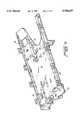
- FIG. 1is an top isometric view of a reader/writer apparatus in accordance with this invention.
- FIG. 1Aillustrates the features of a standard smart card and also illustrates a magstripe card or a hybrid card.
- FIG. 2is a bottom isometric view of a reader/writer apparatus in accordance with this invention.
- FIG. 3is an exploded assembly view of a reader/writer apparatus in accordance with this invention.
- FIGS. 4, 5 and 5Adepict features of an upper frame member forming a portion of a reader/writer apparatus in accordance with this invention.
- FIGS. 6 and 7depict features of a lower frame member forming a portion of a reader/writer apparatus in accordance with this invention.
- FIGS. 8A-8Dare miscellaneous views of a connector carriage mechanism useful in a preferred embodiment of a reader/writer apparatus in accordance with this invention.
- FIGS. 9A and 9Billustrate features of a contact set mechanism useful in a connector carriage as shown in FIGS. 8A to 8D.
- FIG. 10illustrates the assembly of a contact set as shown in FIGS. 9A and 9B into a connector carriage as shown in FIGS. 8A-8D for use in a preferred embodiment of a reader/writer apparatus in accordance with this invention.
- FIGS. 11-14are section views illustrating features and operation of a preferred card latch mechanism in accordance with this invention.
- FIGS. 15 and 16are section views of an alternative embodiment of a card latch mechanism in accordance with this invention.
- Reader/writer apparatus 10 for a contact-type smart cardincludes a frame 18 forming a card slot 19 for receiving a smart card 20 shown in dashed lines in FIG. 1 in a partially inserted position.
- reader/writer apparatus 10may also include a mag-stripe card reader assembly 15. Reader/writer apparatus 10 can then operate with either contact type smart cards or mag-stripe data cards or cards which combine the features of a smart card and a mag-stripe card.
- FIG. 1Aillustrates a smart card 20 with a contact pad set 21 thereon for making electrical connections to an integrated circuit which is encapsulated in the plastic of the card body, usually directly under contact pad set 21.
- Mag-stripe cardshave data recorded in magnetic domains on a stripe of magnetizable material 22. The details of the structure and function of both a smart card and a mag-stripe card are well known and will not be discussed here.
- frame 18comprises a upper frame member 11 and a lower frame member 12.
- the terms “upper” and “lower”are used for convenience in distinguishing the two elements of the mechanism. They are not intended to limit the possible orientations in which the reader/writer mechanism of this invention might be employed, e.g. in a vertical position as well as a horizontal position as generally shown in the drawings.!
- a landing contact mechanism 13is carried on frame 18, or more specifically on upper frame member 11, for making electrical contact with contact pads 21 on smart card 20 when fully inserted in card slot 19.
- Landing contact mechanism 13includes connector carriage 30 and a connector block 31 mounted in a recessed portion thereof.
- Connector block 31includes a card contact set 34 (illustrated in detail in FIGS. 9A and 9B) for making actual electrical contact with contact pads 21 on smart card 20. Details of how this connection is made will be discussed below.
- connector carriage 30 and connector block 31could alternatively be fashioned as an integral assembly, i.e. with card contact set 34 and other elements of connector block 31 directly formed on connector carriage 30.
- Connector carriage 13is mounted to frame 18 on a pivot axis 40 so that connector carriage 13 is free to rotate generally in a plane parallel to card slot 19 through a small angle.
- a drive means in the form of post 35is formed on the contact side of connector 13 and contacts a leading edge of a smart card inserted in card slot 19 to rotate the connector carriage through a prearranged angle as the card moves to a predetermined read position within card slot 19.
- the initial and final angular positions of connector carriage 30 and thus the predetermined angle of rotation of connector carriage 30is controlled by guide slot 44 which is best seen in FIGS. 6 and 7.
- Post 35is received in guide slot 44 so that guide slot 44 can provide this angular position control.
- Screw threads 32 and 33 formed on opposite edge portions of connector carriage 30cooperate with mating screw threads 42 and 43 on frame 18 to move connector carriage 30 a predetermined distance into card slot 19 as connector carriage 30 rotates through the prearranged angle.
- This inward movement of connector carriage 30brings connector carriage 30 to a card read position in which the card contact set 34 is in good electrical contact with contacts 21 on smart card 20 when inserted to the card read position.
- the overall operationthus involves drive post 35 on connector carriage 30 being contacted by the leading edge of smart card 20 as it nears the card read position. Smart card 20 and connector carriage 30 then move together as smart card 20 is pushed further into card slot 19 with connector carriage 30 rotating and moving toward smart card 20 to land the card contact set 34 onto the contact pads 21 of smart card 20.
- the magnitude of inward movement of connector carriage 30is designed to produce an adequate wiping action of the spring loaded contacts of card contact set 34 as the contacts land on the individual one of the contact pads 21 of smart card 20 and the tolerances of this action are well known and need not be discussed here.
- connector carriage 30rotates through an angle of ten degrees and the cooperating screw threads are designed to produce an inward movement of connector carriage 30 of one millimeter.
- Tension spring 41is coupled between connector carriage 30 and frame 18 to bias connector carriage 30 toward an initial rest position in which post 35 is in contact with the forwardmost wall of guide slot 44.
- a card latch arrangement 14 including latch arm 51 and solenoid latch release mechanism 52is mounted on frame 18 and operates when the smart card 20 is inserted to the read position such that latch arm 51 latches smart card 20 in the card read position and thereby latches connector carriage 30 in its read position. Solenoid latch release mechanism 52 operates to release latch arm 51 and this permits tension spring 41 to return connector carriage 30 from its read position to its initial rest position. As connector carriage 30 moves back to its rest position, post 35 drives inserted smart card 20 partially out of card slot 19.
- Frame 18has an open region 45 in upper frame wall 46, which wall forms a portion of card slot 19. Open region 45 admits connector carriage 30 and connector block 31 into card slot 19 so that connector block 31 can make contact with an inserted smart card 20.
- a mounting flange 47 and a mounting post 48are formed on one side of open region 45 for defining the pivot axis of connector carriage 30.
- Aperture 36 on connector carriage 30receives mounting post 48.
- Screw thread portions 42 and 43are formed on interior edge portions of open region 45 as shown. Screw threads 32 on connector carriage 30 engage screw threads 43 on upper frame wall 46. Screw threads 33 engage screw threads 42 on upper frame wall 46.
- Frame 18 and specifically upper frame wall 46has a recessed area 49 adjacent to and communicating with open region 45 and a spring mounting post 49A.
- Connector carriage 30has a spring mounting aperture 37 means formed thereon.
- Tension spring 41connects on one end to spring mounting post 49A and on the other end to spring mounting aperture 37. As previously discussed, tension spring 41 biases connector carriage 30 toward its initial or rest position and returns it to that position when solenoid latch release mechanism 52 operates to put latch arm 51 in its card release position.
- Elongated latch arm 51is pivotally mounted on lower frame wall 60 via a mounting post 54 received in mounting bracket 62 on lower frame wall 60.
- a latch head element 53is formed one end of latch arm 51 and latch head element 53 extends into card slot 19 through an open region 61 formed in lower frame wall 60.
- Elongated latch arm 51pivots between a card admit/release position shown in FIG. 12 and a card latch position shown in FIG. 12.
- a card latch compression spring 55is mounted between frame 18, specifically upper frame wall 46, and latch arm 51 as shown in FIG. 11. Card latch compression spring 55 is captured in recesses 63A and 63B in upper frame wall 46 and latch arm 51 as shown.
- Latch head element 53has a sloped surface 53A facing toward the card entry portion of card slot 19 and this sloped surface permits the leading edge of an inserted card to move latch head element 53 to the card admit position.
- the rounded bottom portion of latch head element 53rides up on the surface of smart card 20 as shown in FIG. 12 until the trailing edge of smart card 20 card passes latch head element 53. This happens as smart card 20 reaches the card read position within card slot 19.
- Card latch compression spring 55then pivots latch arm 51 to return latch head element 53 to the card latch position as shown in FIG. 13. In this relative positioning of smart card 20 and latch head element 53, smart card 20 is precluded from being manually removed from card slot 19 by card latch surface 53B which faces away from the card entry portion of card slot 19. As shown in FIG.
- a lower portion of latch head element 53extends into a open region 101 in upper frame wall 46 to ensure that smart card 20 is securely latched in the card read position.
- the card latch position of latch arm 51maintains smart card 20 in the read position and the latched card maintains connector carriage 30 in the read position by resisting the return action of tension spring 41.
- the reader/writer mechanism of this inventionwould be integrated into a housing that would block access of a cardholder from the opening 101 in lower frame wall 60 of lower frame member 12. In other words, the cardholder would not be able to reach under and use a finger to unlatch the card reader/writer.
- Solenoid latch release mechanism 52includes a solenoid 70 with an extended core piece 71 as shown best in FIG. 14. Solenoid 70 is carried in a bracket 74 which is mounted to lower frame wall 60 at mounting structure 75 using a pair of screws 73. A latch release lever 72 of generally L-shape is mounted in pivotal manner in a release lever bracket 64 formed on lower frame wall 60. One leg of latch release lever 72 is operatively associated with the end of core piece 71 of solenoid 70 and the other with a latch arm release point 56 of latch arm 51.
- FIG. 14shows latch arm release point 56 in a position relating to the card admit position of latch arm 51 when a smart card 20 is being inserted in the reader/writer mechanism. When latch arm 51 is in a card latch position, the upper surface of latch arm release point 56 is in contact with the upper leg of latch release lever 72 and is held there by the pressure of compression spring 55.
- latch release lever 72pivots and forces latch arm release point 56 down and thus pivots latch arm 51 to its card accept position and holds it there while solenoid 70 is operated.
- Solenoid 70need only be operated momentarily since, as soon as latch arm 51 is in the card accept/release position, tension spring 41 associated with connector carriage 30 will return connector carriage 30 to its initial position which will, in turn, drive smart card 20 partially out of card slot 19. Once smart card 20 is pushed away from the card read position, latch arm 51 is riding on top of smart card 20 and latch arm 51 remains in the card accept/release position until smart card 20 is manually withdrawn from card slot 19.
- latch release mechanismscould be employed in the reader/writer mechanism of this invention.
- a manual latch release arrangementcould readily be substituted for the solenoid operated release mechanism by providing a release button that extends outside the case of the device.
- a manual release buttoncould be hidden inside a door of the housing in which the reader/writer apparatus 10 is mounted.
- a small holecould be included in the housing through which the end of a paper clip could be inserted to push a latch release button.
- the smart card reader/writer mechanism of this inventionmay also be adapted to read mag-stripe cards using a mag-stripe reader mechanism 15 comprising a read head 90 and a read head mounting bracket 91.
- Read head 90has a front data pick up face which extends through an opening 92 in lower frame wall 60 into card slot 19 so as to contact a mag-stripe region of a card inserted into card slot 19.
- FIGS. 4, 5 and 5Aare different views of upper frame member 11 showing the details of its structure.
- FIGS. 6 and 7are different views of lower frame member 12 illustrating details of its structure.
- upper frame wall 46 and lower frame wall 60are adapted to snap together to form frame 18. This snap together assembly arrangement is a preferred one from an ease of assembly standpoint, but of course alternative assembly arrangements could be employed.
- Upper frame member 11includes wall structures forming the side walls of card slot 19. In this manner, upper frame member 11 controls the positioning of an inserted smart card 20 relative to the connector carriage 30 and connector block 31 and contacts thereon for making reliable connections to smart card 20.
- FIGS. 8A-8D together with FIGS. 9A, 9B, and 10,illustrate details of connector carriage 30 and connector block 31 and how connector block 31 mounts on connector carriage 30.
- Connector carriage 30has a recessed area 110 that is sized and shaped to receive connector block 31.
- An arrangement of slots 111 in recessed area 110accommodate connector leads 112 on connector block 31 as connector block 31 is inserted in recessed area 110.
- Connector block 31includes a card-in switch arrangement 115 which detects when the leading edge of smart card 20 is in position contacting drive post 35 on connector carriage 30.
- Card-in switch 115closes a short time before the smart card 20 and connector carriage 30 travel the final short distance to the final contact position of connector carriage 30 and connector block 31 with contacts 116 of connector block 31 landed on contact pads on smart card 20. This short time delay is taken into account in the electronics portion (i.e. in either hardware or software) of an overall smart card reader/writer apparatus in which reader/writer mechanism 10 is employed.
- drive post 35could operate a separate microswitch mounted in a position to be closed when connector carriage 30 is driven to its final read position by the leading edge of smart card 20.
- another switch(not shown) could be mounted in association with elongated latch arm 51 to indicate when it is in the card latched position.
- the reader/writer softwarewould then know that a smart card 20 is fully inserted to the read position when both switches are closed. This latter arrangement would prevent the reader/writer from trying to read a smart card 20 which is only inserted far enough to activate the card-in switch 115, but not to bring smart card 20 to the fully inserted read position.
- Reader/writer apparatus 10is designed for ease of assembly as well as simplicity, low-cost and reliability. Referring to exploded assembly drawing of FIG. 3, supplemented by the other drawing figures, assembly operations of reader/writer mechanism 10 involve the following steps:
- Compression spring 55is placed into recessed area 63A.
- Latch head element 53 of elongated latch arm 51is placed in opening 61 with pin 54 in position to slide into rocker bracket 62.
- Compression spring 55is compressed by pushing down on the back portion of elongated latch arm 51 and then elongated latch arm 51 is moved forward to position pins 54 in rocker bracket 62.
- mag-head 90is placed in aperture 92 in lower frame member 12.
- the mounting arrangementprovides for two different mounting positions for different two-track reading specifications.
- Mounting frame 91is than snapped onto lower frame member 12 to capture the mag-head in position.
- Latch release lever 72is placed in mounting bracket 64 of lower frame member 12, preferably using a needle nose pliers to compress the sides of lever 72 until it is inserted, and thereafter releasing the sides so that pins thereon are captured in the bracket. Alternatively, this step can be done by hand if a person's fingers are strong enough to provide the compression force. Solenoid assembly 52 is placed into its mounting bracket 75 and two screws 73 are driven into threaded apertures 74A to hold solenoid 70 in position.
- Connector block 31is mounted in recessed portion 110 of connector carriage 30. Then connector carriage 30 is mounted onto upper frame member 11 by placing aperture 36 in position to receive mounting post 48 and then rotating the unit to gradually engage the cooperating screw threads 32,43 and 33,42.
- a needle nose pliersis preferable used to attach the ends of tension spring 41 to aperture 37 on connector carriage 30 and to mounting pin 49A on upper frame member 11. This latter step can also be done by hand manipulation of tension spring 41.
- a flex cable(not shown) is soldered to the pins 112 on connector block 31 and also to the pins on mag-head 90, if included in the reader/writer mechanism 10.
- FIGS. 15 and 16illustrate schematically an alternative form of card latch mechanism.
- a latch arm 151is mounted for pivoting about the point 162 and has a latch head element 153 on one end and a card actuating ramp 154 on the other end.
- a bistable spring element 155holds latch head element 153 in the card accept position as smart card 20 is being inserted in card slot 119.
- latch arm 151pivots upon further inward movement of smart card 20 and latch head element 153 moves into position to block card removal from card slot 119.
- bistable spring 155is actuated to its alternative stable state which maintains latch head 153 in the latched position.
- landing contact mechanism 13pushes smart card 20 back a short distance to rest against latch head 153 which is arranged to be the final read position of smart card 20.
- latch head 153which is arranged to be the final read position of smart card 20.
- solenoid 152is actuated to move bistable spring 155 back to the unlatched state. This pivots elongated latch arm 151 to the card accept position and allows the return spring on landing contact mechanism 13 to drive smart card 20 partially out of card slot 119.
Landscapes
- Engineering & Computer Science (AREA)
- Artificial Intelligence (AREA)
- Computer Vision & Pattern Recognition (AREA)
- Physics & Mathematics (AREA)
- General Physics & Mathematics (AREA)
- Theoretical Computer Science (AREA)
- Details Of Connecting Devices For Male And Female Coupling (AREA)
Abstract
Description
Claims (6)
Priority Applications (4)
| Application Number | Priority Date | Filing Date | Title |
|---|---|---|---|
| US08/729,366US5780827A (en) | 1996-10-16 | 1996-10-16 | Landing contact mechanism and card latch for smart card reader/writer |
| PCT/US1997/017546WO1998016899A1 (en) | 1996-10-16 | 1997-10-16 | Landing contact mechanism and card latch for smart card reader/writer |
| AU47404/97AAU4740497A (en) | 1996-10-16 | 1997-10-16 | Landing contact mechanism and card latch for smart card reader/writer |
| US09/078,361US6138916A (en) | 1996-10-16 | 1998-05-13 | Landing contact mechanism and card latch for smart card reader/writer |
Applications Claiming Priority (1)
| Application Number | Priority Date | Filing Date | Title |
|---|---|---|---|
| US08/729,366US5780827A (en) | 1996-10-16 | 1996-10-16 | Landing contact mechanism and card latch for smart card reader/writer |
Related Child Applications (1)
| Application Number | Title | Priority Date | Filing Date |
|---|---|---|---|
| US09/078,361DivisionUS6138916A (en) | 1996-10-16 | 1998-05-13 | Landing contact mechanism and card latch for smart card reader/writer |
Publications (1)
| Publication Number | Publication Date |
|---|---|
| US5780827Atrue US5780827A (en) | 1998-07-14 |
Family
ID=24930719
Family Applications (2)
| Application Number | Title | Priority Date | Filing Date |
|---|---|---|---|
| US08/729,366Expired - LifetimeUS5780827A (en) | 1996-10-16 | 1996-10-16 | Landing contact mechanism and card latch for smart card reader/writer |
| US09/078,361Expired - LifetimeUS6138916A (en) | 1996-10-16 | 1998-05-13 | Landing contact mechanism and card latch for smart card reader/writer |
Family Applications After (1)
| Application Number | Title | Priority Date | Filing Date |
|---|---|---|---|
| US09/078,361Expired - LifetimeUS6138916A (en) | 1996-10-16 | 1998-05-13 | Landing contact mechanism and card latch for smart card reader/writer |
Country Status (3)
| Country | Link |
|---|---|
| US (2) | US5780827A (en) |
| AU (1) | AU4740497A (en) |
| WO (1) | WO1998016899A1 (en) |
Cited By (18)
| Publication number | Priority date | Publication date | Assignee | Title |
|---|---|---|---|---|
| US5984179A (en)* | 1996-10-15 | 1999-11-16 | Ncr Corporation | Card reader/writer with pivoting read/write contact head |
| US6116933A (en)* | 1998-10-22 | 2000-09-12 | Itt Manufacturing Enterprises, Inc. | Card reader |
| US6138916A (en)* | 1996-10-16 | 2000-10-31 | Verifone, Inc. | Landing contact mechanism and card latch for smart card reader/writer |
| FR2795242A1 (en)* | 1999-06-16 | 2000-12-22 | Kel Kk | Electronic card connector with compact card insertion guides |
| US6234844B1 (en) | 2000-06-28 | 2001-05-22 | Berg Technology, Inc. | Electronic card connector |
| US6349880B1 (en)* | 1999-05-17 | 2002-02-26 | Valeo Securite Habitacle | Arrangement for the interchange of data between a rigid or semi-rigid data medium and a data interchange device |
| USD454875S1 (en) | 1999-12-29 | 2002-03-26 | Tyco Electronics Logistics Ag | Single smart card reader |
| USD456407S1 (en) | 1999-12-29 | 2002-04-30 | Tyco Electronics Logistics Ag | Stacked smart card reader |
| US6382508B1 (en)* | 1997-12-10 | 2002-05-07 | Amphenol-Tuchel Electronics Gmbh | Contacting apparatus for a smart card |
| US6402033B1 (en)* | 1998-01-22 | 2002-06-11 | Timelox Ab | Method for reading and writing a smart card |
| US6508673B2 (en) | 2000-04-05 | 2003-01-21 | Mcdowell Jennifer Lyn | Low cost smart card reader, extension style, with wiping contacts |
| US6592031B1 (en)* | 1998-12-04 | 2003-07-15 | Stocko Contact Gmbh & Co. Kg | Authentication system for PC cards |
| USD529029S1 (en)* | 2004-06-11 | 2006-09-26 | J.S.T. Mfg. Co., Ltd. | Memory card adapter |
| USD615983S1 (en) | 2007-12-06 | 2010-05-18 | Sony Corporation | Adapter for memory card |
| USD658185S1 (en)* | 2009-09-30 | 2012-04-24 | Sony Corporation | Memory card adapter |
| US8190513B2 (en) | 1996-06-05 | 2012-05-29 | Fraud Control Systems.Com Corporation | Method of billing a purchase made over a computer network |
| US8229844B2 (en) | 1996-06-05 | 2012-07-24 | Fraud Control Systems.Com Corporation | Method of billing a purchase made over a computer network |
| US8630942B2 (en) | 1996-06-05 | 2014-01-14 | Fraud Control Systems.Com Corporation | Method of billing a purchase made over a computer network |
Families Citing this family (17)
| Publication number | Priority date | Publication date | Assignee | Title |
|---|---|---|---|---|
| FR2786297B1 (en)* | 1998-11-19 | 2001-01-19 | Valeo Securite Habitacle | ARRANGEMENT FOR LOCKING A DATA MEDIUM IN A DATA EXCHANGE DEVICE |
| JP3362691B2 (en)* | 1999-03-08 | 2003-01-07 | 松下電器産業株式会社 | IC card reader |
| FR2793921B1 (en)* | 1999-05-17 | 2001-06-29 | Itt Mfg Enterprises Inc | COMPACT ASSEMBLY FOR CONNECTING A CARD WITH AN INTEGRATED CIRCUIT (S) COMPRISING MEANS OF EJECTING THE CARD |
| DE19930389B4 (en)* | 1999-07-01 | 2009-09-17 | Amphenol-Tuchel Electronics Gmbh | Card reader for smart cards and / or SIM cards of different thickness |
| JP4240706B2 (en)* | 1999-08-23 | 2009-03-18 | ソニー株式会社 | Storage medium loading device |
| EP1170692B1 (en)* | 2000-07-07 | 2009-03-25 | AMPHENOL-TUCHEL ELECTRONICS GmbH | A smart-card reader |
| GB2367673A (en)* | 2000-10-03 | 2002-04-10 | Nokia Mobile Phones Ltd | Smart card reader module |
| US6604685B1 (en) | 2001-07-02 | 2003-08-12 | Bellsouth Intellectual Property Corporation | Optical smart card system, apparatus and method |
| US6572015B1 (en) | 2001-07-02 | 2003-06-03 | Bellsouth Intellectual Property Corporation | Smart card authorization system, apparatus and method |
| US6616054B1 (en)* | 2001-07-02 | 2003-09-09 | Bellsouth Intellectual Property Corporation | External power supply system, apparatus and method for smart card |
| US6705531B1 (en) | 2001-07-02 | 2004-03-16 | Bellsouth Intellectual Property Corp. | Smart card system, apparatus and method with alternate placement of contact module |
| JP3828003B2 (en)* | 2001-12-04 | 2006-09-27 | 日本電産サンキョー株式会社 | IC card reader |
| US7017811B2 (en)* | 2004-05-18 | 2006-03-28 | Computerized Security Systems | Electronic card encoder |
| DE102004040448B4 (en)* | 2004-08-20 | 2010-01-21 | Amphenol-Tuchel Electronics Gmbh | Pushmatic Smart Card Connector |
| US20060076412A1 (en)* | 2004-10-13 | 2006-04-13 | Yen-Hung Chen | Card reading apparatus |
| CN101686270A (en)* | 2008-09-25 | 2010-03-31 | 深圳富泰宏精密工业有限公司 | Locking structure for SIM card |
| GB2508351A (en)* | 2012-11-28 | 2014-06-04 | Pulse Function F6 Ltd | A card fixing device for mounting a card in a device so that it is difficult to remove |
Citations (25)
| Publication number | Priority date | Publication date | Assignee | Title |
|---|---|---|---|---|
| US4404464A (en)* | 1978-01-24 | 1983-09-13 | Moreno Roland C D | Method and apparatus for electrically connecting a removable article, in particular a portable electronic card |
| US4443049A (en)* | 1978-12-27 | 1984-04-17 | Compagnie Internationale Pour L'informatique Cii-Honeywell Bull (Societe Anonyme) | Connector for portable objects such as credit cards |
| US4449775A (en)* | 1978-12-27 | 1984-05-22 | Compaganie Internationale Pour L'informatique Cii-Honeywell Bull (Societe Anonyme) | Connector for portable objects such as credit cards |
| US4527052A (en)* | 1983-03-29 | 1985-07-02 | Burroughs Corporation | Autoteller card handling mechanism |
| US4602351A (en)* | 1983-07-06 | 1986-07-22 | Tokyo Tatsuno Co., Ltd. | Device for reading and writing IC-external storage cards |
| US4724310A (en)* | 1984-07-02 | 1988-02-09 | Tokyo Tatsuno Co., Ltd. | Device for inserting and holding an IC card as an external memory during reading and writing operations |
| US4734567A (en)* | 1985-09-18 | 1988-03-29 | Siemens Aktiengesellschaft | Locking and unlocking device for a card reader |
| US4743746A (en)* | 1984-12-11 | 1988-05-10 | Nixdorf Computer Ag | Receiving unit for a data card containing an electronic circuit |
| US4795897A (en)* | 1986-02-21 | 1989-01-03 | U.S. Philips Corp. | Apparatus for establishing data transfers with a portable electronic card |
| US4843221A (en)* | 1986-07-26 | 1989-06-27 | Daiichi Denshi Kogyo Kabushiki Kaisha | Electronic card receiving device |
| US4864114A (en)* | 1985-09-12 | 1989-09-05 | Bull, S.A. | Method of and apparatus for confiscating a data bearing card |
| US4904852A (en)* | 1986-12-12 | 1990-02-27 | Omron Tateisi Electronics Co. | IC card reader |
| US4926032A (en)* | 1987-03-12 | 1990-05-15 | Tokyo Tatsuno Co., Ltd. | Reader and/or writer for IC card |
| US4931622A (en)* | 1985-08-09 | 1990-06-05 | Daiichi Denshi Kogyo Kabushiki Kaisha | Electronic card receiving device and ejection mechanism |
| US4932889A (en)* | 1988-03-25 | 1990-06-12 | Amphenol Corporation | Chipcard reader |
| US4940418A (en)* | 1988-04-21 | 1990-07-10 | Oki Electric Industry Co., Ltd. | Card read/write device |
| EP0399763A2 (en)* | 1989-05-23 | 1990-11-28 | Hitachi Maxell Ltd. | IC card reader/writer |
| US4976630A (en)* | 1988-03-25 | 1990-12-11 | Amphenol Corporation | Chipcard reader |
| US5045674A (en)* | 1987-10-21 | 1991-09-03 | Omron Tateisi Electronics Co. | IC card reader/writer having rotating contact support with pin-check verification |
| US5161992A (en)* | 1992-01-17 | 1992-11-10 | Amp Incorporated | Electrical connector assembly for a card containing an integrated circuit chip |
| US5196687A (en)* | 1988-10-14 | 1993-03-23 | Omron Tateisi Electronics Co. | Card reader having locking mechanism |
| US5202551A (en)* | 1990-06-01 | 1993-04-13 | U.S. Philips Corporation | Reading device for an integrated circuit card |
| US5243176A (en)* | 1991-02-12 | 1993-09-07 | Compagnie Generale D'automatisme Cga-Hbs | Ic card reader |
| US5331138A (en)* | 1992-11-03 | 1994-07-19 | American Magnetics Corp. | Hybrid card reader |
| US5332889A (en)* | 1992-12-18 | 1994-07-26 | Datacard Corporation | Integrated circuit card programming device |
Family Cites Families (9)
| Publication number | Priority date | Publication date | Assignee | Title |
|---|---|---|---|---|
| US3850299A (en)* | 1973-12-03 | 1974-11-26 | Ncr Co | Card transport and capture mechanism |
| US3909595A (en)* | 1974-08-08 | 1975-09-30 | Diebold Inc | Entry gate construction for credit card actuated automatic remote banking equipment |
| US4358103A (en)* | 1977-02-04 | 1982-11-09 | Canon Kabushiki Kaisha | Magnetic card transporting apparatus |
| US5017764A (en)* | 1987-12-28 | 1991-05-21 | Olympus Optical Co., Ltd. | Apparatus for driving card-like record medium |
| US5146069A (en)* | 1988-09-19 | 1992-09-08 | Fuji Photo Film Co., Ltd. | Device for loading and unloading a memory cartridge using a sliding member |
| JPH05303821A (en)* | 1992-04-24 | 1993-11-16 | Olympus Optical Co Ltd | Recording and reproducing device for card-like recording medium |
| FR2695515B1 (en)* | 1992-09-09 | 1994-11-10 | Francelco Sa | Electrical connector for microcircuit card. |
| JPH08171616A (en)* | 1994-12-19 | 1996-07-02 | Shinei Diecast Kogyo Kk | Card loader |
| US5780827A (en)* | 1996-10-16 | 1998-07-14 | Verifone, Inc. | Landing contact mechanism and card latch for smart card reader/writer |
- 1996
- 1996-10-16USUS08/729,366patent/US5780827A/ennot_activeExpired - Lifetime
- 1997
- 1997-10-16WOPCT/US1997/017546patent/WO1998016899A1/enactiveApplication Filing
- 1997-10-16AUAU47404/97Apatent/AU4740497A/ennot_activeAbandoned
- 1998
- 1998-05-13USUS09/078,361patent/US6138916A/ennot_activeExpired - Lifetime
Patent Citations (26)
| Publication number | Priority date | Publication date | Assignee | Title |
|---|---|---|---|---|
| US4404464A (en)* | 1978-01-24 | 1983-09-13 | Moreno Roland C D | Method and apparatus for electrically connecting a removable article, in particular a portable electronic card |
| US4443049A (en)* | 1978-12-27 | 1984-04-17 | Compagnie Internationale Pour L'informatique Cii-Honeywell Bull (Societe Anonyme) | Connector for portable objects such as credit cards |
| US4449775A (en)* | 1978-12-27 | 1984-05-22 | Compaganie Internationale Pour L'informatique Cii-Honeywell Bull (Societe Anonyme) | Connector for portable objects such as credit cards |
| US4527052A (en)* | 1983-03-29 | 1985-07-02 | Burroughs Corporation | Autoteller card handling mechanism |
| US4602351A (en)* | 1983-07-06 | 1986-07-22 | Tokyo Tatsuno Co., Ltd. | Device for reading and writing IC-external storage cards |
| US4724310A (en)* | 1984-07-02 | 1988-02-09 | Tokyo Tatsuno Co., Ltd. | Device for inserting and holding an IC card as an external memory during reading and writing operations |
| US4743746A (en)* | 1984-12-11 | 1988-05-10 | Nixdorf Computer Ag | Receiving unit for a data card containing an electronic circuit |
| US4931622A (en)* | 1985-08-09 | 1990-06-05 | Daiichi Denshi Kogyo Kabushiki Kaisha | Electronic card receiving device and ejection mechanism |
| US4864114A (en)* | 1985-09-12 | 1989-09-05 | Bull, S.A. | Method of and apparatus for confiscating a data bearing card |
| US4734567A (en)* | 1985-09-18 | 1988-03-29 | Siemens Aktiengesellschaft | Locking and unlocking device for a card reader |
| US4795897A (en)* | 1986-02-21 | 1989-01-03 | U.S. Philips Corp. | Apparatus for establishing data transfers with a portable electronic card |
| US4843221A (en)* | 1986-07-26 | 1989-06-27 | Daiichi Denshi Kogyo Kabushiki Kaisha | Electronic card receiving device |
| US4904852A (en)* | 1986-12-12 | 1990-02-27 | Omron Tateisi Electronics Co. | IC card reader |
| US4926032A (en)* | 1987-03-12 | 1990-05-15 | Tokyo Tatsuno Co., Ltd. | Reader and/or writer for IC card |
| US5045674A (en)* | 1987-10-21 | 1991-09-03 | Omron Tateisi Electronics Co. | IC card reader/writer having rotating contact support with pin-check verification |
| US4932889A (en)* | 1988-03-25 | 1990-06-12 | Amphenol Corporation | Chipcard reader |
| US4976630A (en)* | 1988-03-25 | 1990-12-11 | Amphenol Corporation | Chipcard reader |
| US4940418A (en)* | 1988-04-21 | 1990-07-10 | Oki Electric Industry Co., Ltd. | Card read/write device |
| US5196687A (en)* | 1988-10-14 | 1993-03-23 | Omron Tateisi Electronics Co. | Card reader having locking mechanism |
| EP0399763A2 (en)* | 1989-05-23 | 1990-11-28 | Hitachi Maxell Ltd. | IC card reader/writer |
| US5091618A (en)* | 1989-05-23 | 1992-02-25 | Hitachi Maxell, Ltd. | Ic card reader/writer |
| US5202551A (en)* | 1990-06-01 | 1993-04-13 | U.S. Philips Corporation | Reading device for an integrated circuit card |
| US5243176A (en)* | 1991-02-12 | 1993-09-07 | Compagnie Generale D'automatisme Cga-Hbs | Ic card reader |
| US5161992A (en)* | 1992-01-17 | 1992-11-10 | Amp Incorporated | Electrical connector assembly for a card containing an integrated circuit chip |
| US5331138A (en)* | 1992-11-03 | 1994-07-19 | American Magnetics Corp. | Hybrid card reader |
| US5332889A (en)* | 1992-12-18 | 1994-07-26 | Datacard Corporation | Integrated circuit card programming device |
Cited By (18)
| Publication number | Priority date | Publication date | Assignee | Title |
|---|---|---|---|---|
| US8190513B2 (en) | 1996-06-05 | 2012-05-29 | Fraud Control Systems.Com Corporation | Method of billing a purchase made over a computer network |
| US8229844B2 (en) | 1996-06-05 | 2012-07-24 | Fraud Control Systems.Com Corporation | Method of billing a purchase made over a computer network |
| US8630942B2 (en) | 1996-06-05 | 2014-01-14 | Fraud Control Systems.Com Corporation | Method of billing a purchase made over a computer network |
| US5984179A (en)* | 1996-10-15 | 1999-11-16 | Ncr Corporation | Card reader/writer with pivoting read/write contact head |
| US6138916A (en)* | 1996-10-16 | 2000-10-31 | Verifone, Inc. | Landing contact mechanism and card latch for smart card reader/writer |
| US6382508B1 (en)* | 1997-12-10 | 2002-05-07 | Amphenol-Tuchel Electronics Gmbh | Contacting apparatus for a smart card |
| US6402033B1 (en)* | 1998-01-22 | 2002-06-11 | Timelox Ab | Method for reading and writing a smart card |
| US6116933A (en)* | 1998-10-22 | 2000-09-12 | Itt Manufacturing Enterprises, Inc. | Card reader |
| US6592031B1 (en)* | 1998-12-04 | 2003-07-15 | Stocko Contact Gmbh & Co. Kg | Authentication system for PC cards |
| US6349880B1 (en)* | 1999-05-17 | 2002-02-26 | Valeo Securite Habitacle | Arrangement for the interchange of data between a rigid or semi-rigid data medium and a data interchange device |
| FR2795242A1 (en)* | 1999-06-16 | 2000-12-22 | Kel Kk | Electronic card connector with compact card insertion guides |
| USD456407S1 (en) | 1999-12-29 | 2002-04-30 | Tyco Electronics Logistics Ag | Stacked smart card reader |
| USD454875S1 (en) | 1999-12-29 | 2002-03-26 | Tyco Electronics Logistics Ag | Single smart card reader |
| US6508673B2 (en) | 2000-04-05 | 2003-01-21 | Mcdowell Jennifer Lyn | Low cost smart card reader, extension style, with wiping contacts |
| US6234844B1 (en) | 2000-06-28 | 2001-05-22 | Berg Technology, Inc. | Electronic card connector |
| USD529029S1 (en)* | 2004-06-11 | 2006-09-26 | J.S.T. Mfg. Co., Ltd. | Memory card adapter |
| USD615983S1 (en) | 2007-12-06 | 2010-05-18 | Sony Corporation | Adapter for memory card |
| USD658185S1 (en)* | 2009-09-30 | 2012-04-24 | Sony Corporation | Memory card adapter |
Also Published As
| Publication number | Publication date |
|---|---|
| WO1998016899A1 (en) | 1998-04-23 |
| US6138916A (en) | 2000-10-31 |
| AU4740497A (en) | 1998-05-11 |
Similar Documents
| Publication | Publication Date | Title |
|---|---|---|
| US5780827A (en) | Landing contact mechanism and card latch for smart card reader/writer | |
| US5331138A (en) | Hybrid card reader | |
| CA1242527A (en) | Device for inserting and holding an ic card as an external memory during reading and writing operations | |
| US20010008813A1 (en) | IC card connector having IC card ejection mechanism | |
| US20030157839A1 (en) | Ic card connector | |
| US7815449B2 (en) | Memory card connector | |
| JPH06187517A (en) | Portable case of electronic smart card | |
| EP1602058A1 (en) | Connector for a smart card, comprising an integrated drawer/slider for the card | |
| JPH0552991B2 (en) | ||
| US6951473B2 (en) | IC card reader | |
| US6367700B1 (en) | IC card reader | |
| WO2001089041A1 (en) | Ic card connector with card lock | |
| JP4226869B2 (en) | Card connector | |
| EP0923042B1 (en) | Contacting apparatus for a smart card | |
| US20070243736A1 (en) | Memory Card Connector with Card Over-Running Protection | |
| JP3159044B2 (en) | Communication card | |
| JP3887164B2 (en) | Card connector device | |
| KR19990087120A (en) | Monitored 3-Level Hybrid Reader (Maresh Reader) | |
| JP3341140B2 (en) | IC card processing device | |
| KR100500198B1 (en) | Connector device for card | |
| AU633930B2 (en) | Card reader | |
| EP1775802A1 (en) | IC card connector | |
| JPS62100886A (en) | IC card read/write device | |
| JPH08180147A (en) | Ic card access device | |
| JP2743484B2 (en) | IC card reader |
Legal Events
| Date | Code | Title | Description |
|---|---|---|---|
| AS | Assignment | Owner name:VERIFONE INC., CALIFORNIA Free format text:ASSIGNMENT OF ASSIGNORS INTEREST;ASSIGNORS:ZOLKOS, JOHN;NAKAMURA, LANCE;REEL/FRAME:008390/0672;SIGNING DATES FROM 19970203 TO 19970214 | |
| STCF | Information on status: patent grant | Free format text:PATENTED CASE | |
| AS | Assignment | Owner name:HEWLETT-PACKARD COMPANY, CALIFORNIA Free format text:ASSIGNMENT OF ASSIGNORS INTEREST;ASSIGNOR:VERIFONE INC.;REEL/FRAME:009764/0442 Effective date:19990224 | |
| AS | Assignment | Owner name:HEWLETT-PACKARD COMPANY, COLORADO Free format text:MERGER;ASSIGNOR:HEWLETT-PACKARD COMPANY;REEL/FRAME:011523/0469 Effective date:19980520 | |
| FEPP | Fee payment procedure | Free format text:PAYOR NUMBER ASSIGNED (ORIGINAL EVENT CODE: ASPN); ENTITY STATUS OF PATENT OWNER: LARGE ENTITY | |
| FPAY | Fee payment | Year of fee payment:4 | |
| REMI | Maintenance fee reminder mailed | ||
| AS | Assignment | Owner name:GUARANTY BUSINESS CRESIT CORPORATION, CALIFORNIA Free format text:SECURITY AGREEMENT;ASSIGNOR:VERIFONE, INC.;REEL/FRAME:012581/0809 Effective date:20020116 | |
| AS | Assignment | Owner name:VERIFONE, INC., CALIFORNIA Free format text:RELEASE OF SECURITY INTEREST;ASSIGNOR:GUARANTY BUSINESS CREDIT CORPORATION;REEL/FRAME:013663/0615 Effective date:20020702 | |
| FPAY | Fee payment | Year of fee payment:8 | |
| FPAY | Fee payment | Year of fee payment:12 | |
| AS | Assignment | Owner name:VERIFONE INTERMEDIATE HOLDINGS, INC. & VERIFONE, I Free format text:PATENT RELEASE AGREEMENT;ASSIGNOR:JPMORGAN CHASE BANK, N.A., AS ADMINISTRATIVE AGENT;REEL/FRAME:027465/0567 Effective date:20111228 |