US5779996A - Microbial remediation reactor and process - Google Patents
Microbial remediation reactor and processDownload PDFInfo
- Publication number
- US5779996A US5779996AUS08/708,118US70811896AUS5779996AUS 5779996 AUS5779996 AUS 5779996AUS 70811896 AUS70811896 AUS 70811896AUS 5779996 AUS5779996 AUS 5779996A
- Authority
- US
- United States
- Prior art keywords
- blade
- vessel
- settled bed
- reactor
- fluid
- Prior art date
- Legal status (The legal status is an assumption and is not a legal conclusion. Google has not performed a legal analysis and makes no representation as to the accuracy of the status listed.)
- Expired - Lifetime
Links
- 238000000034methodMethods0.000titleclaimsdescription38
- 238000005067remediationMethods0.000titleabstractdescription8
- 230000000813microbial effectEffects0.000titleabstractdescription7
- 239000012530fluidSubstances0.000claimsabstractdescription48
- 239000002002slurrySubstances0.000claimsabstractdescription47
- 239000007787solidSubstances0.000claimsabstractdescription39
- 239000000725suspensionSubstances0.000claimsabstractdescription31
- 239000007788liquidSubstances0.000claimsabstractdescription29
- 238000002156mixingMethods0.000claimsabstractdescription26
- 244000005700microbiomeSpecies0.000claimsabstractdescription25
- 239000002245particleSubstances0.000claimsabstractdescription18
- 239000000356contaminantSubstances0.000claimsabstractdescription11
- 235000015097nutrientsNutrition0.000claimsabstractdescription3
- 239000002689soilSubstances0.000claimsdescription23
- 238000001914filtrationMethods0.000claimsdescription7
- 239000010802sludgeSubstances0.000claimsdescription7
- 239000010808liquid wasteSubstances0.000claimsdescription5
- 239000002699waste materialSubstances0.000claimsdescription3
- 239000007789gasSubstances0.000abstractdescription30
- 239000004576sandSubstances0.000abstractdescription30
- 238000005243fluidizationMethods0.000abstractdescription17
- 239000013049sedimentSubstances0.000abstractdescription16
- 230000002708enhancing effectEffects0.000abstractdescription4
- 230000003134recirculating effectEffects0.000abstractdescription3
- 239000013618particulate matterSubstances0.000abstractdescription2
- 239000011261inert gasSubstances0.000abstract1
- XLYOFNOQVPJJNP-UHFFFAOYSA-NwaterSubstancesOXLYOFNOQVPJJNP-UHFFFAOYSA-N0.000description50
- 239000002028BiomassSubstances0.000description12
- 238000006065biodegradation reactionMethods0.000description9
- 230000000694effectsEffects0.000description9
- 239000000126substanceSubstances0.000description9
- 239000002351wastewaterSubstances0.000description9
- 230000015556catabolic processEffects0.000description8
- 238000006731degradation reactionMethods0.000description8
- 238000013461designMethods0.000description8
- 238000011001backwashingMethods0.000description7
- 238000013019agitationMethods0.000description6
- 238000006243chemical reactionMethods0.000description6
- 239000000463materialSubstances0.000description6
- QVGXLLKOCUKJST-UHFFFAOYSA-Natomic oxygenChemical compound[O]QVGXLLKOCUKJST-UHFFFAOYSA-N0.000description5
- 230000014759maintenance of locationEffects0.000description5
- 229910052760oxygenInorganic materials0.000description5
- 239000001301oxygenSubstances0.000description5
- 238000005273aerationMethods0.000description4
- 238000005516engineering processMethods0.000description4
- 238000013459approachMethods0.000description3
- 230000029087digestionEffects0.000description3
- 230000001965increasing effectEffects0.000description3
- 239000010865sewageSubstances0.000description3
- 239000003039volatile agentSubstances0.000description3
- YVGGHNCTFXOJCH-UHFFFAOYSA-NDDTChemical compoundC1=CC(Cl)=CC=C1C(C(Cl)(Cl)Cl)C1=CC=C(Cl)C=C1YVGGHNCTFXOJCH-UHFFFAOYSA-N0.000description2
- 238000003795desorptionMethods0.000description2
- 238000005187foamingMethods0.000description2
- 231100001261hazardousToxicity0.000description2
- 239000002920hazardous wasteSubstances0.000description2
- 239000000203mixtureSubstances0.000description2
- 230000001590oxidative effectEffects0.000description2
- 239000000575pesticideSubstances0.000description2
- 239000004033plasticSubstances0.000description2
- 229920003023plasticPolymers0.000description2
- 230000009331reductive pathwayEffects0.000description2
- 238000003756stirringMethods0.000description2
- 238000010408sweepingMethods0.000description2
- 230000002588toxic effectEffects0.000description2
- KVGZZAHHUNAVKZ-UHFFFAOYSA-N1,4-DioxinChemical compoundO1C=COC=C1KVGZZAHHUNAVKZ-UHFFFAOYSA-N0.000description1
- WHRZCXAVMTUTDD-UHFFFAOYSA-N1h-furo[2,3-d]pyrimidin-2-oneChemical compoundN1C(=O)N=C2OC=CC2=C1WHRZCXAVMTUTDD-UHFFFAOYSA-N0.000description1
- 241000894006BacteriaSpecies0.000description1
- OKTJSMMVPCPJKN-UHFFFAOYSA-NCarbonChemical compound[C]OKTJSMMVPCPJKN-UHFFFAOYSA-N0.000description1
- 241000195493CryptophytaSpecies0.000description1
- 241000233866FungiSpecies0.000description1
- 235000006173Larrea tridentataNutrition0.000description1
- 244000073231Larrea tridentataSpecies0.000description1
- 239000004698PolyethyleneSubstances0.000description1
- 238000005276aeratorMethods0.000description1
- 241001148470aerobic bacillusSpecies0.000description1
- 238000005842biochemical reactionMethods0.000description1
- 230000008236biological pathwayEffects0.000description1
- 229910052799carbonInorganic materials0.000description1
- 239000000969carrierSubstances0.000description1
- 230000003197catalytic effectEffects0.000description1
- 238000001311chemical methods and processMethods0.000description1
- 239000007795chemical reaction productSubstances0.000description1
- BIWJNBZANLAXMG-YQELWRJZSA-NchloordaanChemical compoundClC1=C(Cl)[C@@]2(Cl)C3CC(Cl)C(Cl)C3[C@]1(Cl)C2(Cl)ClBIWJNBZANLAXMG-YQELWRJZSA-N0.000description1
- 150000001875compoundsChemical class0.000description1
- 229960002126creosoteDrugs0.000description1
- 230000001351cycling effectEffects0.000description1
- 230000007423decreaseEffects0.000description1
- 230000001419dependent effectEffects0.000description1
- 239000005446dissolved organic matterSubstances0.000description1
- 238000009826distributionMethods0.000description1
- 238000005265energy consumptionMethods0.000description1
- 230000002255enzymatic effectEffects0.000description1
- 239000006260foamSubstances0.000description1
- 239000004615ingredientSubstances0.000description1
- 238000002347injectionMethods0.000description1
- 239000007924injectionSubstances0.000description1
- 229910010272inorganic materialInorganic materials0.000description1
- 239000011147inorganic materialSubstances0.000description1
- 231100001231less toxicToxicity0.000description1
- 238000012423maintenanceMethods0.000description1
- 210000004379membraneAnatomy0.000description1
- 238000012544monitoring processMethods0.000description1
- 150000002894organic compoundsChemical class0.000description1
- 239000005416organic matterSubstances0.000description1
- 238000006213oxygenation reactionMethods0.000description1
- 230000037361pathwayEffects0.000description1
- IZUPBVBPLAPZRR-UHFFFAOYSA-NpentachlorophenolChemical compoundOC1=C(Cl)C(Cl)=C(Cl)C(Cl)=C1ClIZUPBVBPLAPZRR-UHFFFAOYSA-N0.000description1
- 238000011020pilot scale processMethods0.000description1
- 150000003071polychlorinated biphenylsChemical class0.000description1
- 125000005575polycyclic aromatic hydrocarbon groupChemical group0.000description1
- -1polyethylenePolymers0.000description1
- 229920000573polyethylenePolymers0.000description1
- 235000013824polyphenolsNutrition0.000description1
- 238000012545processingMethods0.000description1
- 238000005086pumpingMethods0.000description1
- 239000000376reactantSubstances0.000description1
- 230000000717retained effectEffects0.000description1
- 230000000630rising effectEffects0.000description1
- 238000009991scouringMethods0.000description1
- 238000012216screeningMethods0.000description1
- 238000004062sedimentationMethods0.000description1
- 238000012163sequencing techniqueMethods0.000description1
- 239000010801sewage sludgeSubstances0.000description1
- 238000001179sorption measurementMethods0.000description1
- 239000006228supernatantSubstances0.000description1
- 231100000331toxicToxicity0.000description1
- 238000012546transferMethods0.000description1
- 238000005406washingMethods0.000description1
- 238000004065wastewater treatmentMethods0.000description1
- 230000003442weekly effectEffects0.000description1
- 239000002023woodSubstances0.000description1
Images


Classifications
- C—CHEMISTRY; METALLURGY
- C02—TREATMENT OF WATER, WASTE WATER, SEWAGE, OR SLUDGE
- C02F—TREATMENT OF WATER, WASTE WATER, SEWAGE, OR SLUDGE
- C02F3/00—Biological treatment of water, waste water, or sewage
- C02F3/02—Aerobic processes
- C02F3/12—Activated sludge processes
- C02F3/1278—Provisions for mixing or aeration of the mixed liquor
- C02F3/1284—Mixing devices
- B—PERFORMING OPERATIONS; TRANSPORTING
- B01—PHYSICAL OR CHEMICAL PROCESSES OR APPARATUS IN GENERAL
- B01F—MIXING, e.g. DISSOLVING, EMULSIFYING OR DISPERSING
- B01F23/00—Mixing according to the phases to be mixed, e.g. dispersing or emulsifying
- B01F23/20—Mixing gases with liquids
- B01F23/23—Mixing gases with liquids by introducing gases into liquid media, e.g. for producing aerated liquids
- B01F23/233—Mixing gases with liquids by introducing gases into liquid media, e.g. for producing aerated liquids using driven stirrers with completely immersed stirring elements
- B—PERFORMING OPERATIONS; TRANSPORTING
- B01—PHYSICAL OR CHEMICAL PROCESSES OR APPARATUS IN GENERAL
- B01F—MIXING, e.g. DISSOLVING, EMULSIFYING OR DISPERSING
- B01F25/00—Flow mixers; Mixers for falling materials, e.g. solid particles
- B01F25/20—Jet mixers, i.e. mixers using high-speed fluid streams
- B01F25/21—Jet mixers, i.e. mixers using high-speed fluid streams with submerged injectors, e.g. nozzles, for injecting high-pressure jets into a large volume or into mixing chambers
- B01F25/212—Jet mixers, i.e. mixers using high-speed fluid streams with submerged injectors, e.g. nozzles, for injecting high-pressure jets into a large volume or into mixing chambers the injectors being movable, e.g. rotating
- B01F25/2122—Rotating during jetting
- B—PERFORMING OPERATIONS; TRANSPORTING
- B01—PHYSICAL OR CHEMICAL PROCESSES OR APPARATUS IN GENERAL
- B01F—MIXING, e.g. DISSOLVING, EMULSIFYING OR DISPERSING
- B01F25/00—Flow mixers; Mixers for falling materials, e.g. solid particles
- B01F25/50—Circulation mixers, e.g. wherein at least part of the mixture is discharged from and reintroduced into a receptacle
- B01F25/53—Circulation mixers, e.g. wherein at least part of the mixture is discharged from and reintroduced into a receptacle in which the mixture is discharged from and reintroduced into a receptacle through a recirculation tube, into which an additional component is introduced
- B—PERFORMING OPERATIONS; TRANSPORTING
- B01—PHYSICAL OR CHEMICAL PROCESSES OR APPARATUS IN GENERAL
- B01F—MIXING, e.g. DISSOLVING, EMULSIFYING OR DISPERSING
- B01F27/00—Mixers with rotary stirring devices in fixed receptacles; Kneaders
- B01F27/55—Mixers with rotary stirring devices in fixed receptacles; Kneaders with stirrers driven by the moving material
- B—PERFORMING OPERATIONS; TRANSPORTING
- B01—PHYSICAL OR CHEMICAL PROCESSES OR APPARATUS IN GENERAL
- B01F—MIXING, e.g. DISSOLVING, EMULSIFYING OR DISPERSING
- B01F35/00—Accessories for mixers; Auxiliary operations or auxiliary devices; Parts or details of general application
- B01F35/30—Driving arrangements; Transmissions; Couplings; Brakes
- B01F35/32—Driving arrangements
- B01F35/32005—Type of drive
- B01F35/3203—Gas driven
- B—PERFORMING OPERATIONS; TRANSPORTING
- B01—PHYSICAL OR CHEMICAL PROCESSES OR APPARATUS IN GENERAL
- B01J—CHEMICAL OR PHYSICAL PROCESSES, e.g. CATALYSIS OR COLLOID CHEMISTRY; THEIR RELEVANT APPARATUS
- B01J19/00—Chemical, physical or physico-chemical processes in general; Their relevant apparatus
- B01J19/18—Stationary reactors having moving elements inside
- B—PERFORMING OPERATIONS; TRANSPORTING
- B01—PHYSICAL OR CHEMICAL PROCESSES OR APPARATUS IN GENERAL
- B01J—CHEMICAL OR PHYSICAL PROCESSES, e.g. CATALYSIS OR COLLOID CHEMISTRY; THEIR RELEVANT APPARATUS
- B01J8/00—Chemical or physical processes in general, conducted in the presence of fluids and solid particles; Apparatus for such processes
- B01J8/08—Chemical or physical processes in general, conducted in the presence of fluids and solid particles; Apparatus for such processes with moving particles
- B01J8/10—Chemical or physical processes in general, conducted in the presence of fluids and solid particles; Apparatus for such processes with moving particles moved by stirrers or by rotary drums or rotary receptacles or endless belts
- B—PERFORMING OPERATIONS; TRANSPORTING
- B01—PHYSICAL OR CHEMICAL PROCESSES OR APPARATUS IN GENERAL
- B01J—CHEMICAL OR PHYSICAL PROCESSES, e.g. CATALYSIS OR COLLOID CHEMISTRY; THEIR RELEVANT APPARATUS
- B01J8/00—Chemical or physical processes in general, conducted in the presence of fluids and solid particles; Apparatus for such processes
- B01J8/18—Chemical or physical processes in general, conducted in the presence of fluids and solid particles; Apparatus for such processes with fluidised particles
- B01J8/20—Chemical or physical processes in general, conducted in the presence of fluids and solid particles; Apparatus for such processes with fluidised particles with liquid as a fluidising medium
- B01J8/22—Chemical or physical processes in general, conducted in the presence of fluids and solid particles; Apparatus for such processes with fluidised particles with liquid as a fluidising medium gas being introduced into the liquid
- B01J8/222—Chemical or physical processes in general, conducted in the presence of fluids and solid particles; Apparatus for such processes with fluidised particles with liquid as a fluidising medium gas being introduced into the liquid in the presence of a rotating device only
- C—CHEMISTRY; METALLURGY
- C02—TREATMENT OF WATER, WASTE WATER, SEWAGE, OR SLUDGE
- C02F—TREATMENT OF WATER, WASTE WATER, SEWAGE, OR SLUDGE
- C02F3/00—Biological treatment of water, waste water, or sewage
- C02F3/02—Aerobic processes
- C02F3/06—Aerobic processes using submerged filters
- C—CHEMISTRY; METALLURGY
- C02—TREATMENT OF WATER, WASTE WATER, SEWAGE, OR SLUDGE
- C02F—TREATMENT OF WATER, WASTE WATER, SEWAGE, OR SLUDGE
- C02F3/00—Biological treatment of water, waste water, or sewage
- C02F3/28—Anaerobic digestion processes
- C—CHEMISTRY; METALLURGY
- C12—BIOCHEMISTRY; BEER; SPIRITS; WINE; VINEGAR; MICROBIOLOGY; ENZYMOLOGY; MUTATION OR GENETIC ENGINEERING
- C12M—APPARATUS FOR ENZYMOLOGY OR MICROBIOLOGY; APPARATUS FOR CULTURING MICROORGANISMS FOR PRODUCING BIOMASS, FOR GROWING CELLS OR FOR OBTAINING FERMENTATION OR METABOLIC PRODUCTS, i.e. BIOREACTORS OR FERMENTERS
- C12M21/00—Bioreactors or fermenters specially adapted for specific uses
- C12M21/04—Bioreactors or fermenters specially adapted for specific uses for producing gas, e.g. biogas
- C—CHEMISTRY; METALLURGY
- C12—BIOCHEMISTRY; BEER; SPIRITS; WINE; VINEGAR; MICROBIOLOGY; ENZYMOLOGY; MUTATION OR GENETIC ENGINEERING
- C12M—APPARATUS FOR ENZYMOLOGY OR MICROBIOLOGY; APPARATUS FOR CULTURING MICROORGANISMS FOR PRODUCING BIOMASS, FOR GROWING CELLS OR FOR OBTAINING FERMENTATION OR METABOLIC PRODUCTS, i.e. BIOREACTORS OR FERMENTERS
- C12M27/00—Means for mixing, agitating or circulating fluids in the vessel
- C12M27/02—Stirrer or mobile mixing elements
- C12M27/04—Stirrer or mobile mixing elements with introduction of gas through the stirrer or mixing element
- C—CHEMISTRY; METALLURGY
- C12—BIOCHEMISTRY; BEER; SPIRITS; WINE; VINEGAR; MICROBIOLOGY; ENZYMOLOGY; MUTATION OR GENETIC ENGINEERING
- C12M—APPARATUS FOR ENZYMOLOGY OR MICROBIOLOGY; APPARATUS FOR CULTURING MICROORGANISMS FOR PRODUCING BIOMASS, FOR GROWING CELLS OR FOR OBTAINING FERMENTATION OR METABOLIC PRODUCTS, i.e. BIOREACTORS OR FERMENTERS
- C12M29/00—Means for introduction, extraction or recirculation of materials, e.g. pumps
- C12M29/02—Percolation
- C—CHEMISTRY; METALLURGY
- C12—BIOCHEMISTRY; BEER; SPIRITS; WINE; VINEGAR; MICROBIOLOGY; ENZYMOLOGY; MUTATION OR GENETIC ENGINEERING
- C12M—APPARATUS FOR ENZYMOLOGY OR MICROBIOLOGY; APPARATUS FOR CULTURING MICROORGANISMS FOR PRODUCING BIOMASS, FOR GROWING CELLS OR FOR OBTAINING FERMENTATION OR METABOLIC PRODUCTS, i.e. BIOREACTORS OR FERMENTERS
- C12M29/00—Means for introduction, extraction or recirculation of materials, e.g. pumps
- C12M29/24—Recirculation of gas
- B—PERFORMING OPERATIONS; TRANSPORTING
- B01—PHYSICAL OR CHEMICAL PROCESSES OR APPARATUS IN GENERAL
- B01F—MIXING, e.g. DISSOLVING, EMULSIFYING OR DISPERSING
- B01F23/00—Mixing according to the phases to be mixed, e.g. dispersing or emulsifying
- B01F23/20—Mixing gases with liquids
- B01F23/23—Mixing gases with liquids by introducing gases into liquid media, e.g. for producing aerated liquids
- B01F23/233—Mixing gases with liquids by introducing gases into liquid media, e.g. for producing aerated liquids using driven stirrers with completely immersed stirring elements
- B01F23/2336—Mixing gases with liquids by introducing gases into liquid media, e.g. for producing aerated liquids using driven stirrers with completely immersed stirring elements characterised by the location of the place of introduction of the gas relative to the stirrer
- B01F23/23364—Mixing gases with liquids by introducing gases into liquid media, e.g. for producing aerated liquids using driven stirrers with completely immersed stirring elements characterised by the location of the place of introduction of the gas relative to the stirrer the gas being introduced between the stirrer elements
- B01F23/233642—Mixing gases with liquids by introducing gases into liquid media, e.g. for producing aerated liquids using driven stirrers with completely immersed stirring elements characterised by the location of the place of introduction of the gas relative to the stirrer the gas being introduced between the stirrer elements at the stirrer elements
- B—PERFORMING OPERATIONS; TRANSPORTING
- B01—PHYSICAL OR CHEMICAL PROCESSES OR APPARATUS IN GENERAL
- B01F—MIXING, e.g. DISSOLVING, EMULSIFYING OR DISPERSING
- B01F35/00—Accessories for mixers; Auxiliary operations or auxiliary devices; Parts or details of general application
- B01F35/30—Driving arrangements; Transmissions; Couplings; Brakes
- B01F35/32—Driving arrangements
- B01F35/32005—Type of drive
- B01F35/32015—Flow driven
- B—PERFORMING OPERATIONS; TRANSPORTING
- B01—PHYSICAL OR CHEMICAL PROCESSES OR APPARATUS IN GENERAL
- B01J—CHEMICAL OR PHYSICAL PROCESSES, e.g. CATALYSIS OR COLLOID CHEMISTRY; THEIR RELEVANT APPARATUS
- B01J2219/00—Chemical, physical or physico-chemical processes in general; Their relevant apparatus
- B01J2219/00049—Controlling or regulating processes
- B01J2219/00162—Controlling or regulating processes controlling the pressure
- B—PERFORMING OPERATIONS; TRANSPORTING
- B01—PHYSICAL OR CHEMICAL PROCESSES OR APPARATUS IN GENERAL
- B01J—CHEMICAL OR PHYSICAL PROCESSES, e.g. CATALYSIS OR COLLOID CHEMISTRY; THEIR RELEVANT APPARATUS
- B01J2219/00—Chemical, physical or physico-chemical processes in general; Their relevant apparatus
- B01J2219/00049—Controlling or regulating processes
- B01J2219/00164—Controlling or regulating processes controlling the flow
- B—PERFORMING OPERATIONS; TRANSPORTING
- B01—PHYSICAL OR CHEMICAL PROCESSES OR APPARATUS IN GENERAL
- B01J—CHEMICAL OR PHYSICAL PROCESSES, e.g. CATALYSIS OR COLLOID CHEMISTRY; THEIR RELEVANT APPARATUS
- B01J2219/00—Chemical, physical or physico-chemical processes in general; Their relevant apparatus
- B01J2219/00049—Controlling or regulating processes
- B01J2219/00189—Controlling or regulating processes controlling the stirring velocity
- Y—GENERAL TAGGING OF NEW TECHNOLOGICAL DEVELOPMENTS; GENERAL TAGGING OF CROSS-SECTIONAL TECHNOLOGIES SPANNING OVER SEVERAL SECTIONS OF THE IPC; TECHNICAL SUBJECTS COVERED BY FORMER USPC CROSS-REFERENCE ART COLLECTIONS [XRACs] AND DIGESTS
- Y02—TECHNOLOGIES OR APPLICATIONS FOR MITIGATION OR ADAPTATION AGAINST CLIMATE CHANGE
- Y02W—CLIMATE CHANGE MITIGATION TECHNOLOGIES RELATED TO WASTEWATER TREATMENT OR WASTE MANAGEMENT
- Y02W10/00—Technologies for wastewater treatment
- Y02W10/10—Biological treatment of water, waste water, or sewage
Definitions
- This inventionrelates to microbial reactors and to microbial reactor systems in general, and more specifically, to a mixer/contactor for a slurry, suspension or settled bed reactor system.
- the mixer contactoris advantageous for processes wherein contact time may be relatively long, and/or wherein minimum energy input for suspending and mixing solid particles in the slurry, suspension or settled bed is desired, for example, in the biological remediation of liquid waste streams or contaminated sludges or soils.
- Slurry or suspension or settled bed reactorsare commonly used for processing ores, soils, and wood chips. Also, they are commonly used to effect the biological, enzymatic or chemical conversion of soluble and insoluble reactants.
- a slurry or suspensionis a mixture of a liquid and solid particles, wherein at least a portion of the solid particles are suspended in the liquid. In a slurry or suspension reactor, a portion of the solid particles may be settled in the bottom of the reactor to form a bed.
- Biodegradation of many of these contaminating chemicalshas been conducted. "Biodegradation” means breaking down these chemicals to less hazardous or less toxic reaction products via biological pathways using microorganisms.
- the microorganisms, or “microbes”may operate aerobically, microaerophylically or anaerobically, or in any combination thereof. Also, the microorganisms may operate via oxidative pathways or reductive pathways. Microorganisms include bacteria, protozoa, fungi and algae. Biodegradation of soils contaminated with chemicals is one way to remediate the soil.
- the remediating microorganismsoperate on the soil contaminating chemicals in a slurry environment in a reactor vessel, wherein the soil is mixed with water to at least partially suspend the soil particles for intimate contact with the microorganisms.
- a gassuch as air in aerobic applications, for example, may be added to the reactor vessel.
- the reactor vesselcontains microorganisms and a slurry, it is referred to as a bioslurry reactor.
- the first systemdeveloped by MOTEC, Inc. of Mt. Juliet, Tenn., involves technology adapted for treatment of pesticides, PCB's, dioxin and halogenated and nonhalogenated organic compounds. While demonstrated to be effective for treating sludge, liquids and soils having high organic concentrations, the MOTEC process has been reported to be less suitable for use with inorganic-laden wastes.
- the MOTEC technologywhich is a sequential process, is also referred to as liquid solid contact digestion (LSCD).
- LSCDliquid solid contact digestion
- the systeminvolves two to three tank digestors which are aerated using air spargers and are agitated using turbine mixers.
- this technologymay be adapted, by use of high shear propeller mixers, to enhance aerobic biological degradation in lagoons.
- the second technologydeveloped by Detox Industries, Inc. of Sugarland, Tex., is intended for use in treating chlordane, myrex, oil, phenolics, polycyclic aromatic hydrocarbons, creosote, pentachlorophenol (PCP) and polychlorinated biphenyls (PCB's).
- the Detox systemincludes an open-topped reaction tank or on-site created lagoon that utilizes a synthetic liner. The tank is adapted to retain a slurry and is fitted with air distributors.
- bioslurry reactorconsisting of several agitated and aerated vessels, has been used in a pesticide spill application by ECOVA of Redmund, Wash.
- the MOTEC, Detox, and ECOVA systems described aboveare operated in batch mode. After the placement of contaminated soil and water into the reactor vessel, the vessel is aerated until a desired residual contaminant level is reached, and then the supernatant water is usually recycled and the slurry is discharged. Due to the ongoing aeration in these systems, many volatile organic substances are not biodegraded but rather are air-stripped. Some systems treat these air-stripped volatiles in a carbon adsorption filter whereas other systems simply discharge them to the atmosphere.
- a fourth systemutilizes a bioreactor that is a tank having a bottom, upstanding walls fixedly mounted thereon and a sealed top or cover, and which is adapted to receive and contain a slurry.
- the tankis fitted with a mechanical mixing means that operates to effectuate agitation and suspension of the solid particles within the slurry housed within the tank.
- An air supplyoperates to provide oxygen, which is a necessary component of the biooxidation reaction taking place within the bioreactor.
- the air supplyalso is configured to provide suspension of the particulates within the slurry liquid housed within the tank.
- an air liftis provided for recirculating particulates which may have settled out of the slurry.
- the Biolift® systemmay be operated in continuous mode by using a screening device and exit conduit located near the top inside the tank to draw off treated water and excess particulate matter.
- Dissolved organic matter and suspended solidsare often removed from wastewaters by a combination of biodegradation and filtration.
- Conventional designs for microbial water treatment processesare based on suspended microorganisms to degrade organic matter in wastewaters. These activated sludge processes are in wide usage, but they are not efficient in removing waste materials, and they require large facilities. Attached-growth systems, with bioreactors packed with inert media on which microorganisms can attach and grow, are much more efficient than suspended growth systems.
- a variety of arrangementshave been used to clean wastewaters using biological treatment and filtration.
- One arrangementhas been bioreactors in line with sedimentation tanks and filters.
- the reactorcan be as simple as a tank where air is injected and aerobic bacteria are grown on inert carriers such as plastics and sand.
- U.S. Pat. No. 5,007,620discloses a bioreactor equipped with a sweeping means adapted for sweeping and scouring the bottom of the bioreactor. Stationary diffusers are used to aerate the bioreactor. By these means, an aerated slurry can be maintained by means of mechanical agitation and aeration.
- a bioreactorcan be operated anaerobically in processes such as anaerobic digestion and denitrification.
- U.S. Pat. No. 3,970,555discloses a method for backwashing a filter by injecting a fluid, such as air or water, to dislodge gas bubbles trapped in a filter bed. Such backwashing also removes solids clogging the filter bed.
- Bioreactors operated with inert media for supporting microbial growthare termed “biofilters”, and have been operated with a stationary filter medium or a movable filter medium.
- the filter mediumtypically consists of plastic materials or inorganic materials such as sand.
- Stationary filter mediamust be periodically cleaned by a reversed-flow washing, termed “backwashing”. Backwashing, especially when done with injected water and air, can effectively clean the medium. However, the backwash fluids must be collected and treated. Also, the biofilter must be periodically removed from service in order to do the backwashing.
- Fluidized bioreactorshave been developed for continuous operation without backwashing (U.S. Pat. No. 5,007,620). However, such bioreactors require continuous agitation with high energy consumption. In addition, fluidized bioreactors cannot clean wastewater by filtration.
- the instant inventionis a slurry mixer/contactor for a slurry, suspension or settled bed reactor system.
- the mixer/contactoris particularly well-suited for the biological remediation of liquid waste streams or contaminated sludges or soils.
- the reactor system having the mixer/contactor of this inventionmay operate with microorganisms living in the reactor aerobically or anaerobically. Also, the reactor system may operate with microorganisms in the reactor using oxidative or reductive pathways to biodegrade contaminants. To further increase activity in the bioreactor, additional ingredients, including solids, liquids or gases, may be added to the slurry, suspension or settled bed in the reactor.
- the reactor having the mixer/contactor in one embodimentis an upright generally cylindrical vessel with a flat bottom and a covered top.
- a vertical conduitalso called a supply conduit, extending from near the top to near the bottom.
- the inlet to at least one generally horizontal, stirrer bladein fluid connection with the vertical conduit.
- the stirrer bladehas outlet openings in it or on it so fluid may pass therethrough.
- the stirrer blademay rotate around the vertical conduit if the conduit is fixed, or the conduit, with the stirrer blade fixed to it, may rotate around in the vessel. In any event, the rotation of the stirrer blade is caused or made easier by the hydraulic forces of fluid flowing out from the stirrer blade.
- This rotationmay be caused or made easier by a fluidization effect, by a jet propulsion effect, or both.
- rotation of the stirrer blademay be created or eased near the bottom of the vessel, enhancing mixing of the microorganisms with the sludge or soil in the slurry, suspension or settled bed in the vessel, without unnecessarily damaging the microorganisms and without having to fluidize the complete vessel contents.
- liquid and/or slurry from near the top of the reactormay be re-distributed into the sediment near the bottom of the reactor for fresh re-contact and further desorption and reaction of contaminants from the sediment to permit further biodegradation.
- the bioreactor vesselhas a water recycle outlet port and a gas recycle outlet port.
- a water recycle outlet conduitleading to the inlet of a water recycle pump.
- the pumpdelivers recycled water back to the bioreactor vessel through a water inlet conduit connected to the vessel at a water recycle inlet port.
- the water inlet portis connected to the vertical conduit in the center of the vessel, and the flow of recycled water helps to provide the hydraulic forces for fluidizing the sediment in the immediate vicinity of the blade and/or the jet propulsion that results in rotation of the stirrer blade.
- a gas recycle outlet conduit leading to the inlet of a gas recycle pump or compressorAt the gas recycle outlet port of the bioreactor vessel is a gas recycle outlet conduit leading to the inlet of a gas recycle pump or compressor.
- the compressormay deliver recycled gas and/or fresh gas to the bioreactor vessel through a gas inlet conduit connected to the vessel at a gas inlet port, or connected to the water inlet conduit. This way, water and gas from the bioreactor vessel may be recycled and provided to the vertical conduit to help create rotation of the stirrer blade, and better mixing and contacting of the slurry or suspension and the microorganisms in the bioreactor vessel.
- the mixer/contactoris one, generally horizontal blade in fluid connection with the vertical conduit.
- the bladehas outlet openings at or near its leading edge so that fluid passing through the vertical conduit and to the blade may pass from the blade through the openings.
- leading edgeof the blade is meant the front edge or side of the blade relative to the direction of rotation of the blade.
- trailing edgeis meant the back edge or side of the blade relative to rotation.
- More than one blademay be used, and blades at various depths in the reactor may also be used. When a plurality of blades is used, they may rotate independently of, or together as a unit with, the other blade(s).
- the fluidization zone created by the flow of fluid from the outlet openings in the bladehas less density than the rest of the slurry, suspension or settled bed throughout the reactor. Therefore, any generally horizontal force on the blade will tend to cause it to rotate into the fluidization zone.
- This horizontal force on the blademay be created by a propulsion jet at the trailing edge of the blade. Or, this horizontal force may be created by the horizontal component of the weight vector from settling sediment on a rear, downwardly sloping portion of the blade as the sediment descends from a fluidized state to a settled state at the trailing edge of the blade. Or, this horizontal force may be created by the input from an external power source, like an electric motor, for example, connected to and rotating the vessel's vertical conduit. Therefore, the blade rotates, or its rotation in the reactor vessel is made easier, due to the hydraulic forces of fluid flowing out from the stirrer blade.
- This inventionalso relates to the use of a single bioreactor to achieve both biological degradation and the filtration of suspended solids.
- the mixing/contacting bladeintermittently suspends the filtration medium as the blade rotates through the medium to efficiently backwash and clean it.
- One objective of this inventionis to provide an efficient biofilter equipped with a filter bed through which movable blades can be propelled by the injection of fluids, such as air and water. Thereby, the filter bed can be intermittently suspended and efficiently cleaned of trapped solids and gases.
- Another objectiveis to provide a biofilter capable of both microbial degradation of wastewater contaminants and contaminant removal by filtration.
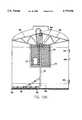
- FIG. 1is a partial side view of one embodiment of the reactor of this invention.
- FIG. 2is a schematic, cross-sectional view of the reactor depicted in FIG. 1, showing some of the reactor's internal structure.
- FIG. 3is a schematic, top cross-sectional view of the reactor depicted in FIGS. 1 and 2.
- FIG. 4is a cross-sectional side view of the mixer/contactor blade of the invention, from the line 4--4 in FIG. 2.
- FIG. 5is a schematic, cross-sectional view of the reactor depicted in FIGS. 1-4, showing the reactor's additional external equipment.
- FIG. 6is a schematic, partial detail isometric view of one embodiment of the mixer/contactor blade of the invention, showing the fluid flow lines out from it during operation.
- FIG. 7is a view as in FIG. 6, but of another embodiment of the mixer/contactor blade.
- FIG. 8is a view as in FIGS. 6 and 7, but of yet another embodiment of the mixer/contactor blade.
- FIG. 9is a partial, cross-sectional side view from line 9--9 of the mixer/contactor blade depicted in FIG. 8, showing the fluidization effect and the propulsion effect in the settled bed around the blade.
- FIG. 10is a schematic, partial side view of another embodiment of the invention with a plurality of mixer/contactor blades at different depths in the reactor.
- FIG. 11Ais a schematic, side cross-sectional view of another embodiment of a reactor of the invention with a submersible pump in it.
- FIGS. 11B and 11Care schematic detail side and top views, respectively, of reactor internals for the embodiment of FIG. 11A.
- reactor 10is an upright, generally cylindrical vessel 11 with a flat bottom 12 and a conical top 13.
- conical top 13is optional fill port 14 and gas recycle outlet ports 15 and 15(A).
- Conical top 13fits within annular water seal 16, which has water seal overflow port 17.
- water recycle outlet port 18In the side wall of cylindrical vessel 11 are water recycle outlet port 18, water recycle inlet port 19, drain port 20, viewing window 21, and sample ports 22, 22A, 22B, and 22C.
- reactor 10has water seal 16 and a vertical conduit 23 supported along the centerline of vessel 11 by bracing 24 and 24A.
- Vertical conduit 23terminates near the bottom 12 of vessel 11 at "T" fluid connection 25.
- "T” connection 25is rotatably supported on bottom 12 by spindle bearing 26.
- the blades 27 and 27Aare in fluid connection with vertical conduit 23, and have in them openings 28, 28A, 28B, 28C, and 28D.
- reactor 10has cylindrical vessel 11 with water seal 16, and bracing 24, 24A, 24B, and 24C for supporting vertical conduit 23.
- bracing 24, 24A, 24B, and 24Cfor supporting vertical conduit 23.
- At the bottom end of vertical conduit 23are horizontal stirrer blades 27 and 27A.
- vertical conduit 23rotates, and it is rotatably supported near its top in the bracing by hub bearing 29.
- stirrer blade 27Ahas a generally triangular cross-sectional shape.
- the circular "T" connection 25 inlet to the blade 27Ais indicated at 30.
- bolts 31 with leading edge retainers 32 and 32Aare provided to stiffen and stabilize blade 27A.
- a fluid flow path or gap 32Bis provided at several locations along the leading length of the blade 27A between it and edge retainer 32A. This way, fluid can exit the blade 27A at gaps 32B and fluidize the sediment bed, and propel the blade around in the reactor.
- reactor 10has gas recycle outlet port 15 and gas recycle outlet conduit 33 leading to air pump or compressor 34.
- recycle outlet conduit 33is optional 4-way gas valve 35.
- Air pump 34discharges compressed recycle gas into gas inlet conduit 36, which is connected and discharges into water recycle inlet conduit 37.
- Recycle inlet conduit 37is connected on its first end to water pump 38, and on its second end to water recycle inlet port 19.
- interior conduit 39is connected on its first end to inlet port 19, and on its second end to the first end of rotating swivel connection 40.
- Swivel connection 40is supported by hub 29 as shown in FIG. 3, and connected on its second end to vertical conduit 23.
- Swivel connection 40permits interior conduit 39 to be fixably connected to inlet port 19 and swivel connection 40, and, at the same time, permits vertical conduit 23 to be rotatably connected to swivel connection 40. This way, vertical conduit 23, "T" connection 25 and stirrer blades 27 and 27A may rotate inside vessel 11.
- Recycle outlet port 18is equipped on the inside of vessel 11 with an outlet screen 41. Screen 41 prevents the solid particles in the slurry or suspension greater than the size of the screen openings from exiting the vessel 11. Water recycle, however, is permitted to exit outlet port 18, and travels via water recycle outlet conduit 42 to the inlet of water pump 38.
- the discharge of water pump 38travels via inlet conduit 37, inlet port 19, interior conduit 39, swivel connection 40, vertical conduit 23, "T" connection 25, “T” connection inlet 30, and stirrer blades 27 or 27A back into the interior of vessel 11 near its bottom.
- the reactormay be operated with, for example, soil slurries at greater than 50 wt % total solids.
- the bioreactorhas four basic modes of operation.
- the water and air pumpsare controlled by a repeat cycle timer that allows either or both pumps to be operated intermittently or continuously.
- First ModeIn the first mode of operation, water is recirculated through the blade which fluidizes the slurry, suspension or settled bed in front of the blade and propels the stirrer through the slurry, bringing fresh liquid in contact with the soil for rapid mixing.
- the water exiting the nozzlepropels the stirrer and also brings solids up into suspension from the bottom and rapidly mixes them. If the circulation is for a short time, the solids are mixed but not so much that they are fully suspended and sucked into the recycle outlet.
- the air pumpcan be added to the operation, allowing very efficient aeration for aerobic reactions, and increasing vertical mixing with the rising bubbles. Since the water and air are both under pressure, the amount of oxygen dissolved in the water can be increased considerably above saturation at atmospheric pressure. For high biological oxygen demand (BOD) systems, this will allow significantly higher oxygen mass transfer rates than for a normally bubbled and stirred reactor. If foaming is a problem with a specific slurry or suspension, the addition of air can be intermittent, with the foam subsiding when air is not being added.
- One way to add air to the operationis to provide a bubbleless oxygenation tube at the discharge of the air pump or compressor 34.
- air pump or compressor 34For example, with three-way valve 60 in gas inlet conduit 36 and with bubbleless oxygenator 61 in recycle inlet conduit 37, air under pressure is routed through oxygenator 61 into reactor 11. This way, foaming in reactor 11 may be minimized.
- Bubbleless oxygenator tubesare available from, for example, Membran Corp., Minneapolis, Minn., U.S.A.
- the air pumpwill pump headspace gases as recycle gases into the water recycle flow, thereby increasing the mixing rates and allowing more complete degradation of volatile compounds in the slurry. This will also increase vertical mixing in anaerobic operations and reintroduce volatiles into the slurry for further degradation.
- the fourth mode of operationis a combination of the above modes; the modes can be operated on an intermittent basis to reduce operational costs or to maintain microaerophilic conditions. Also, by switching between the second and third modes with the 4-way valve 35, there will be no excess aeration or volatiles lost. This system can be easily interfaced with a computer for active control of the operating mode.
- the reactorhas the additional benefits of being an intermittently cleaned sand filter with very high biomass retention.
- the bioreactormay be used as an intermittently backwashed sand filter without substantial biodegradation. This allows for very efficient space utilization and exceptionally low effluent BOD and suspended solids concentration for a single-pass aerobic or anaerobic reactor.
- This systemcan also operate as a sequencing batch reactor, and/or as a mixed mode reactor with both aerobic and anaerobic operations.
- fresh wastewater or soil slurrymay be added to the water recycle outlet conduit 42, and excess treated water removed from drain port 20 at the bottom of the reactor. This may be done without significant loss of the sand or the biomass from the interior of the reactor if a suitable screen is used inside drain port 20. Depending on the source of fresh waste-water, it may be supplied directly to the blade through vertical conduit 23, and not through the recycle pump.
- This novel slurry reactoris an intermittently mixed reactor that has the capability of intermittently fluidizing over 50% wt/wt sand with complete mixing occurring every minute in a 200 gallon pilot-scale reactor.
- the sand in the reactorcan also be operated very efficiently as an anaerobic expended bed bioreactor with intermittent mixing ( ⁇ 5% of the time) and still have very complete and thorough mixing.
- High biomass retentionallows for an old sludge age and very high degradation rates.
- the sand layeracts as sand filter as the water is removed from the bottom of the reactor. Any suspended material, including biomass, is retained by the sand filter therefore allowing very high biomass densities to be maintained, with resulting very high activity.
- the backwashing cyclemay be controlled by monitoring the pressure drop across the settled bed or the flow rate out of the drain port. A pressure drop above the set-point, or a flow rate below the set-point, would initiate the backwash cycle.
- the reactorcan be fully fluidized and the recycle can be directed to a suitable container for a settling basin.
- An alternate wasting methodis to drain some of the liquid away before directing the recycle to a suitable settling basin.
- This wasting cyclecan be incorporated into a weekly operation, or it could possibly be an automatic part of the normal cycling of the reactor.
- the intermittent mixing of only about 5% of the timeconsumes very little energy, but has significant advantages in both the operation and efficiency of the degradation.
- the range of wastewater strengths as influentcan vary from about 300 to greater than 30,000 mg/l COD depending on the final design of the system.
- An embodimentcould also include more than one reactor in series or parallel with effluent from either below the sand level or from above the sand level from the first reactor (which would likely be operating in an anaerobic mode) to a second reactor which could be operating aerobically and the effluent from the second reactor could be moved from below the sand level for very good effluent quality.
- the second reactoractually be two reactors in parallel, then these two reactors could operate in alternating batch mode which would enable effluent to be drawn from one of the two reactors that had just completed a settling mode.
- This embodimentwould not require the removal of the water from below the sand but it would not preclude it either.
- One of the series of reactorscould be setup for a denitrification process as is well known in the industry.
- the lower region of sandcould be anaerobic for denitrification to occur.
- Swivels of some companiesallow two or more isolated flows to occur so the liquid from the aerobic region would only fluidize the upper sand and liquid from the anaerobic portion could be used to fluidize the lower portion.
- An alternate method to have two different redox states in the sand regionsis to have a two speed pump or other flow control means on the recycle flow so that at a low flow only the upper sand is fluidized but at higher flow rates the complete bed is mixed.
- triangular stirrer blade 43has fluidization openings 44 in its front, or leading, side, and jet propulsion opening 45 in its back, or trailing, side.
- jet propulsion opening 45When fluid is directed into blade 43 from vertical conduit 23, "T" connector 25 and "T” connector inlet 30, the fluid flows out from fluidization openings 44 and jet propulsion opening 45.
- round stirrer blade 46has fluidization openings 47 and 47A which are the outlets of relatively short conduits welded parallel to the leading edge of blade 46.
- the conduit 49is very short and its opening 47 is near vertical conduit 23.
- the conduit 50is longer and its opening 47A is near the middle of stirrer blade 46.
- Both openings 47 and 47Aare pointed parallel to the leading edge of blade 46. This way, the fluidization zone created by fluid flowing out of openings 47 and 47A is at or near the leading edge of blade 46.
- round stirrer blade 46has jet propulsion opening 48 in its back, or trailing, side.
- round stirrer blade 51has fluidization openings 52 in its front side, and jet propulsion opening 53 in its back side.
- fluidWhen fluid is directed into blade 51 from vertical conduit 23, "T" connector 25 and “T” connector inlet 30, the fluid flows out from fluidization openings 52 and jet propulsion opening 53.
- zone 54the outflow of fluid from fluidization openings 52 in stirrer blade 51 creates a zone 54 of fluidized sediment in the region in front of blade 51 near the openings 52.
- Zone 54has relatively less density than non-fluidized zone 55 that exists behind blade 51 and elsewhere in the sediment throughout the reactor. Therefore, the tendency is for blade 51 to rotate in the direction of fluidized zone 54 whenever any rotational force is exerted on blade 51, that is, in the direction of the arrow in FIGS. 6-8.
- blade 51rotates around the bottom of reactor 10, fluidizing a relatively small segment of the sediment bed before it as it rotates.
- the solid particles that make up the sediment bedare periodically mixed and recontacted with fresh feed or recycle flowing out from openings 52, enhancing desorption of contaminants from them, and biodegradation.
- FIGS. 4, 6-9illustrate stirrer blades that comprise an elongated member which is generally hollow and that have fluid outlet openings at or near their leading sides.
- FIGS. 4, 6, 8 and 9illustrate stirrer blades in which the leading side outlet openings comprise apertures located in the main, elongated hollow stirring member.
- FIG. 7,illustrates a stirrer blade with a leading side comprising horizontal conduit members, attached to the main member, for the outlet openings.
- the main, elongated stirring memberoptionally may be solid rather than hollow, especially if no trailing side jet is desired.
- reactor 10has several vertical conduits 56A, 56B and 56C, and several rotary unions 57A, 57B and 57C connecting the vertical conduits.
- Each rotary unionhas a horizontally-extending hollow stirrer blade, 58A, 58B and 58C, respectively.
- Interior conduit 39is connected to the top of rotary union 57A.
- the bottom of rotary union 57Cis rotatably supported by spindle bearing 26.
- the blades 58A, 58B and 58Care in fluid connection with the respective rotary unions 57A, 57B and 57C, which in turn are in fluid connection with the respective vertical conduits 56A, 56B and 56C.
- blades 58A, 58B, and 58Cmay rotate independently of one another, in mixed combination of independent or dependent rotation, or all together as a unit. This way, the blades may rotate in the settled bed at one speed, and in the slurry or suspension above the settled bed at a different speed.
- blade 58Ait can be seen that small "T" fittings may be added to the fluid outlet openings to better control the direction of fluid flow from the openings.
- the T-fittingsmay be at -45° to +45° from parallel to the blade.
- FIGS. 11A, 11B, and 11Cshow another scheme for mounting the blade assembly inside an inexpensive tank (i.e. polyethylene 8-12 ft diameter, by 8-14 ft high).
- the center hatched areais a cylindrical, screened region in which may be located submersible pump.
- a wiper/scraper/brushmay be mounted on the central conduit for rotating around with the blade to clean the screen
- the pillow blocks(with split halves) may be both above the water level for accessibility and ease in removing the blade if needed and for trouble free service.
- the lower, left outlet pipeis for removing water as filtered water, from below the sand bed through the slotted screen (available from Cook Screen Company and others).
- the lower right pipecould be for water coming into the reactor and also for wasting solids (but not the sand) by stopping the mixing and allowing solids to settle and then opening or pumping out of that port.
- the upper right pipecould be a fill port or an overflow port if it were higher.
- the top viewshows the upper two truss braces are welded together with the lower one bolted to it after inserting everything into the tank through the 3 foot diameter access port.
- the cycle timemay be timer-controlled, for example, or it may be controlled by the pressure drop across the sand bed, or it may be controlled by a flow control valve on the outlet pipe from drain port 20. By having a pump on the outlet pipe, a much higher flow rate could pass through the sand and the reactor would operate more as a filter as a bioreactor with a very short retention time.
- the stirrer or mixer/contactor blade of this inventionmay be practiced in several embodiments.
- the size and shape of the blademay be varied, as long as outlet openings may be placed at or near its leading edge, and as long as the trailing side of the blade is dissimilar from the leading side.
- the trailing sidemay be dissimilar from the leading side in that the number and/or type of fluid outlet openings are different from those of the leading side.
- the trailing sidemay have one fluid outlet while the leading side has a plurality of outlets, as shown in FIG. 7.
- the trailing sidemay have no fluid outlets, while the leading side does have outlets.
- the trailing sidemay be dissimilar from the leading side in its shape or profile.
- the bladehas a shape which encourages sediment settling on it to be directed towards the trailing edge of the blade as the sediment continues to descend.
- the horizontal component of the weight vector from the settling sedimentpushes the blade forward into the fluidization zone at the front of the blade.
- the blademay be shaped to have a side profile similar in general shape to an airplane wing. When the blade is shaped appropriately, adequate forward horizontal force is supplied by the settling sediment, making optional the propulsion jet opening(s) at the trailing edge of the blade.
- the selection or design of a particular blade for use in the inventiondepends upon many factors, including: the type of liquid and the size and density distributions of the solid particles; the rate of the biodegradation reactions; etc. Therefore, a preferred blade design depends upon many factors like these.
- a motorized deviceto assure rotation of the blade would fall within the scope of this invention.
- One main aspect of this inventionis to provide energy to fluidize material in the immediate vicinity of the blade and then move this fluidized zone around the complete reactor. Whether or not the rotational force comes solely from the hydraulic forces or also from a mechanical torque provider is also within the scope of this invention.
- a motorized drive meansis not needed to power the blade(s).
- a motor, or other braking meansmay be added to slow, or otherwise control the speed of the rotating blade(s).
Landscapes
- Chemical & Material Sciences (AREA)
- Life Sciences & Earth Sciences (AREA)
- Organic Chemistry (AREA)
- Engineering & Computer Science (AREA)
- Health & Medical Sciences (AREA)
- Chemical Kinetics & Catalysis (AREA)
- Microbiology (AREA)
- Bioinformatics & Cheminformatics (AREA)
- Wood Science & Technology (AREA)
- Zoology (AREA)
- Genetics & Genomics (AREA)
- General Engineering & Computer Science (AREA)
- General Health & Medical Sciences (AREA)
- Biochemistry (AREA)
- Biomedical Technology (AREA)
- Biotechnology (AREA)
- Sustainable Development (AREA)
- Water Supply & Treatment (AREA)
- Environmental & Geological Engineering (AREA)
- Hydrology & Water Resources (AREA)
- Biodiversity & Conservation Biology (AREA)
- Molecular Biology (AREA)
- Combustion & Propulsion (AREA)
- General Chemical & Material Sciences (AREA)
- Oil, Petroleum & Natural Gas (AREA)
- Biological Treatment Of Waste Water (AREA)
- Mixers Of The Rotary Stirring Type (AREA)
- Treatment Of Sludge (AREA)
- Apparatus Associated With Microorganisms And Enzymes (AREA)
- Soil Working Implements (AREA)
- Processing Of Solid Wastes (AREA)
- Activated Sludge Processes (AREA)
- Purification Treatments By Anaerobic Or Anaerobic And Aerobic Bacteria Or Animals (AREA)
- Preparation Of Compounds By Using Micro-Organisms (AREA)
Abstract
Description
Claims (22)
Priority Applications (8)
| Application Number | Priority Date | Filing Date | Title |
|---|---|---|---|
| US08/708,118US5779996A (en) | 1995-04-21 | 1996-09-03 | Microbial remediation reactor and process |
| JP51288498AJP2001500056A (en) | 1996-09-03 | 1997-09-03 | Microbial reforming reactor and process |
| CA002264144ACA2264144C (en) | 1996-09-03 | 1997-09-03 | Microbial remediation reactor and process |
| AU43326/97AAU719698B2 (en) | 1996-09-03 | 1997-09-03 | Microbial remediation reactor and process |
| DE1997620501DE69720501T2 (en) | 1996-09-03 | 1997-09-03 | METHOD AND DEVICE FOR BIOLOGICAL REFURBISHMENT |
| AT97941414TATE236091T1 (en) | 1996-09-03 | 1997-09-03 | METHOD AND DEVICE FOR BIOLOGICAL REMEDIATION |
| PCT/US1997/015558WO1998009919A1 (en) | 1996-09-03 | 1997-09-03 | Microbial remediation reactor and process |
| EP97941414AEP0938456B1 (en) | 1996-09-03 | 1997-09-03 | Microbial remediation process and apparatus therefor |
Applications Claiming Priority (2)
| Application Number | Priority Date | Filing Date | Title |
|---|---|---|---|
| US08/426,566US5616304A (en) | 1995-04-21 | 1995-04-21 | Slurry reactor |
| US08/708,118US5779996A (en) | 1995-04-21 | 1996-09-03 | Microbial remediation reactor and process |
Related Parent Applications (1)
| Application Number | Title | Priority Date | Filing Date |
|---|---|---|---|
| US08/426,566Continuation-In-PartUS5616304A (en) | 1995-04-21 | 1995-04-21 | Slurry reactor |
Publications (1)
| Publication Number | Publication Date |
|---|---|
| US5779996Atrue US5779996A (en) | 1998-07-14 |
Family
ID=24844431
Family Applications (1)
| Application Number | Title | Priority Date | Filing Date |
|---|---|---|---|
| US08/708,118Expired - LifetimeUS5779996A (en) | 1995-04-21 | 1996-09-03 | Microbial remediation reactor and process |
Country Status (8)
| Country | Link |
|---|---|
| US (1) | US5779996A (en) |
| EP (1) | EP0938456B1 (en) |
| JP (1) | JP2001500056A (en) |
| AT (1) | ATE236091T1 (en) |
| AU (1) | AU719698B2 (en) |
| CA (1) | CA2264144C (en) |
| DE (1) | DE69720501T2 (en) |
| WO (1) | WO1998009919A1 (en) |
Cited By (39)
| Publication number | Priority date | Publication date | Assignee | Title |
|---|---|---|---|---|
| WO2000021635A1 (en)* | 1998-10-09 | 2000-04-20 | University Technologies International Inc. | Slow sand filter for use with intermittently flowing water supply and method of use thereof |
| US6080906A (en)* | 1997-09-18 | 2000-06-27 | Alliedsignal, Inc. | Demilitarization of chemical munitions |
| US6346412B1 (en) | 1997-09-03 | 2002-02-12 | Newbio, Inc. | Microbial remediation reactor and process |
| US20040104167A1 (en)* | 2002-08-04 | 2004-06-03 | Dennis Chilcote | Method and apparatus for enhancing filter bed performance |
| US20040238430A1 (en)* | 2003-05-30 | 2004-12-02 | Moya Emmanuel G. | Sand filter with rotating vanes |
| US20060104871A1 (en)* | 2002-09-04 | 2006-05-18 | Susumu Natsuyama | Fluidized bed device |
| US20070196535A1 (en)* | 2002-08-07 | 2007-08-23 | Gimar Tecno S.R.L. | Wine storing apparatus |
| US7326564B2 (en) | 2001-02-20 | 2008-02-05 | St. Jude Medical, Inc. | Flow system for medical device evaluation and production |
| US20080223618A1 (en)* | 2007-03-16 | 2008-09-18 | Warren Tobin A | Upright tank jet system |
| US7654728B2 (en) | 1997-10-24 | 2010-02-02 | Revalesio Corporation | System and method for therapeutic application of dissolved oxygen |
| US20100178685A1 (en)* | 2006-10-25 | 2010-07-15 | Andreas Kloss | Method and device for aeration, particularly for microbiological fermentation and for cell cultivation |
| US7770814B2 (en) | 1997-10-24 | 2010-08-10 | Revalesio Corporation | System and method for irrigating with aerated water |
| US7806584B2 (en) | 1997-10-24 | 2010-10-05 | Revalesio Corporation | Diffuser/emulsifier |
| US7832920B2 (en) | 2006-10-25 | 2010-11-16 | Revalesio Corporation | Mixing device for creating an output mixture by mixing a first material and a second material |
| US20100297705A1 (en)* | 2009-05-20 | 2010-11-25 | Xyleco, Inc. | Processing biomass |
| US7887698B2 (en) | 1997-10-24 | 2011-02-15 | Revalesio Corporation | Diffuser/emulsifier for aquaculture applications |
| US20110068058A1 (en)* | 2008-05-20 | 2011-03-24 | Beijing Ecojoy Water Technology Co., Ltd. | Apparatus and process for treating wastewater |
| US20120100572A1 (en)* | 2009-05-20 | 2012-04-26 | Xyleco, Inc. | Bioprocessing |
| US8445546B2 (en) | 2006-10-25 | 2013-05-21 | Revalesio Corporation | Electrokinetically-altered fluids comprising charge-stabilized gas-containing nanostructures |
| US8591957B2 (en) | 2006-10-25 | 2013-11-26 | Revalesio Corporation | Methods of therapeutic treatment of eyes and other human tissues using an oxygen-enriched solution |
| US8609148B2 (en) | 2006-10-25 | 2013-12-17 | Revalesio Corporation | Methods of therapeutic treatment of eyes |
| US8617616B2 (en) | 2006-10-25 | 2013-12-31 | Revalesio Corporation | Methods of wound care and treatment |
| US8784897B2 (en) | 2006-10-25 | 2014-07-22 | Revalesio Corporation | Methods of therapeutic treatment of eyes |
| US8784898B2 (en) | 2006-10-25 | 2014-07-22 | Revalesio Corporation | Methods of wound care and treatment |
| CN103978022A (en)* | 2014-04-18 | 2014-08-13 | 杭州师范大学 | Device for soil heavy metal obstructing and control technology research |
| US8815292B2 (en) | 2009-04-27 | 2014-08-26 | Revalesio Corporation | Compositions and methods for treating insulin resistance and diabetes mellitus |
| US8980325B2 (en) | 2008-05-01 | 2015-03-17 | Revalesio Corporation | Compositions and methods for treating digestive disorders |
| US9198929B2 (en) | 2010-05-07 | 2015-12-01 | Revalesio Corporation | Compositions and methods for enhancing physiological performance and recovery time |
| US9492404B2 (en) | 2010-08-12 | 2016-11-15 | Revalesio Corporation | Compositions and methods for treatment of taupathy |
| US9523090B2 (en) | 2007-10-25 | 2016-12-20 | Revalesio Corporation | Compositions and methods for treating inflammation |
| US9534242B2 (en) | 2009-05-20 | 2017-01-03 | Xyleco, Inc. | Processing biomass |
| US9683250B2 (en) | 2011-02-14 | 2017-06-20 | Xyleco, Inc. | Processing paper feedstocks |
| US9745567B2 (en) | 2008-04-28 | 2017-08-29 | Revalesio Corporation | Compositions and methods for treating multiple sclerosis |
| US10125359B2 (en) | 2007-10-25 | 2018-11-13 | Revalesio Corporation | Compositions and methods for treating inflammation |
| US11185800B2 (en)* | 2017-08-15 | 2021-11-30 | Conopco, Inc. | Apparatus and method for filtering aqueous liquid |
| US20220081665A1 (en)* | 2020-09-16 | 2022-03-17 | Patrick Power | Bioreactor apparatus |
| CN114515747A (en)* | 2022-01-21 | 2022-05-20 | 广西博世科环保科技股份有限公司 | Microorganism mineralization reaction system and method for non-ferrous metal smelting slag |
| US20220232810A1 (en)* | 2019-06-19 | 2022-07-28 | Wallenius Water Innovation Ab | An aquaculture system and methods for circulating and treating fluid therein |
| US11938525B2 (en)* | 2021-06-23 | 2024-03-26 | Guangdong Brunp Recycling Technology Co., Ltd. | Reaction kettle cleaning device |
Families Citing this family (12)
| Publication number | Priority date | Publication date | Assignee | Title |
|---|---|---|---|---|
| AU5613199A (en)* | 1998-09-11 | 2000-04-03 | J. Wayne Van Toever | Fluidized radial flow bioreactor utilizing pellet media |
| JP4528988B2 (en)* | 2000-03-24 | 2010-08-25 | 東京利根開発株式会社 | Dioxin separation method and treatment method |
| JP2005313159A (en)* | 2004-03-31 | 2005-11-10 | Rom:Kk | Contaminated soil or contaminated water purification method and contaminated soil or contaminated water purification device |
| GB2457681B (en)* | 2008-02-21 | 2013-02-27 | Farm Renewable Enviromental Energy Ltd | A gas actuated mixing system |
| CN102161047B (en)* | 2010-12-08 | 2012-12-12 | 沈阳大学 | Experiment device for remediation of solid waste by anaerobes |
| EP2827975B1 (en)* | 2012-03-23 | 2016-05-18 | EKATO Rühr- und Mischtechnik GmbH | System and method for starting up stirring machines in a sediment |
| CN105498586A (en)* | 2016-01-07 | 2016-04-20 | 永胜机械工业(昆山)有限公司 | Premixing tank for polyvinyl chloride resin production |
| DE102018120217A1 (en)* | 2018-08-20 | 2020-02-20 | Tristan Wilms | Device and method for the simultaneous biological purification of waste water, in particular waste water with a biodegradable load, and provision of cooled air |
| JP7190853B2 (en)* | 2018-09-20 | 2022-12-16 | アルテミラ製缶株式会社 | Thickener |
| CN112062432A (en)* | 2020-09-10 | 2020-12-11 | 广州市水电建设工程有限公司 | Sediment microorganism injection device |
| CN113754129A (en)* | 2021-09-27 | 2021-12-07 | 广西世逸翔环保科技股份有限公司 | Rural domestic sewage resourceful classification equipment of energy-efficient integration |
| JP7643826B1 (en)* | 2024-10-10 | 2025-03-11 | ▲き▼ 張 | Waste treatment equipment |
Citations (15)
| Publication number | Priority date | Publication date | Assignee | Title |
|---|---|---|---|---|
| US1478222A (en)* | 1922-09-22 | 1923-12-18 | Hansen Canning Machinery Corp | Cooker |
| US1527404A (en)* | 1920-02-13 | 1925-02-24 | Lucius A Haller | Sifting and mixing machine |
| US3152982A (en)* | 1963-01-24 | 1964-10-13 | Pagnotti Joseph Ross | Method and apparatus for sewage treatment |
| US4728082A (en)* | 1986-02-07 | 1988-03-01 | Envirotech Corporation | Apparatus for biological processing of metal containing ores |
| US4732608A (en)* | 1986-02-07 | 1988-03-22 | Envirotech Corporation | Method for biological processing of metal-containing ores |
| US4974816A (en)* | 1986-02-07 | 1990-12-04 | Envirotech Corporation | Method and apparatus for biological processing of metal-containing ores |
| US5007620A (en)* | 1986-02-07 | 1991-04-16 | Envirotech Corporation | Apparatus for biological processing of metal-containing ores |
| US5034131A (en)* | 1988-11-29 | 1991-07-23 | Outokumpu Oy | Method for treating waste material |
| US5055204A (en)* | 1989-08-29 | 1991-10-08 | Bogart John D | Soil and sludge treatment apparatus and method including agitation, aeration and recirculation |
| US5057284A (en)* | 1986-02-07 | 1991-10-15 | Envirotech | Bioslurry reactor for treatment of slurries containing minerals, soils and sludges |
| US5061080A (en)* | 1990-11-21 | 1991-10-29 | Roberts Filter Manufacturing Company | Rotary agitator |
| US5102803A (en)* | 1990-12-06 | 1992-04-07 | Weaver Lloyd E | Sewage sludge and organic garbage composting apparatus |
| US5227136A (en)* | 1986-02-07 | 1993-07-13 | Envirotech Corporation | Bioslurry reactor for treatment of slurries containing minerals, soils and sludges |
| US5342429A (en)* | 1993-05-05 | 1994-08-30 | Aluminum Company Of America | Purification of molten aluminum using upper and lower impellers |
| US5616304A (en)* | 1995-04-21 | 1997-04-01 | Innovative Biosystems, Inc. | Slurry reactor |
Family Cites Families (5)
| Publication number | Priority date | Publication date | Assignee | Title |
|---|---|---|---|---|
| DE3306071A1 (en)* | 1983-02-22 | 1984-08-23 | Wilfried Dipl.-Ing. 4930 Detmold Hacheney | DEVICE FOR PRODUCING HIGH QUALITY SOLID-LIQUID MIXTURES |
| NO844767L (en)* | 1983-11-30 | 1985-05-31 | Clearfield Nv | fermentation |
| FR2561232B1 (en)* | 1984-03-14 | 1986-10-31 | Rech Prod Agents Chimi Et | PROCESS FOR PURIFYING AN EFFLUENT BY ANAEROBIC FERMENTATION AND SLUDGE BED REACTOR FOR THE IMPLEMENTATION OF THIS PROCESS |
| JP2987461B2 (en)* | 1990-04-20 | 1999-12-06 | 伸洋産業株式会社 | Garbage decomposition equipment |
| IT1264669B1 (en)* | 1993-07-05 | 1996-10-04 | Comer Spa | REACTOR FOR THE REMOVAL OF IMPURITIES FROM A LIQUID |
- 1996
- 1996-09-03USUS08/708,118patent/US5779996A/ennot_activeExpired - Lifetime
- 1997
- 1997-09-03EPEP97941414Apatent/EP0938456B1/ennot_activeExpired - Lifetime
- 1997-09-03CACA002264144Apatent/CA2264144C/ennot_activeExpired - Fee Related
- 1997-09-03WOPCT/US1997/015558patent/WO1998009919A1/enactiveIP Right Grant
- 1997-09-03AUAU43326/97Apatent/AU719698B2/ennot_activeCeased
- 1997-09-03ATAT97941414Tpatent/ATE236091T1/ennot_activeIP Right Cessation
- 1997-09-03DEDE1997620501patent/DE69720501T2/ennot_activeExpired - Fee Related
- 1997-09-03JPJP51288498Apatent/JP2001500056A/enactivePending
Patent Citations (15)
| Publication number | Priority date | Publication date | Assignee | Title |
|---|---|---|---|---|
| US1527404A (en)* | 1920-02-13 | 1925-02-24 | Lucius A Haller | Sifting and mixing machine |
| US1478222A (en)* | 1922-09-22 | 1923-12-18 | Hansen Canning Machinery Corp | Cooker |
| US3152982A (en)* | 1963-01-24 | 1964-10-13 | Pagnotti Joseph Ross | Method and apparatus for sewage treatment |
| US5007620A (en)* | 1986-02-07 | 1991-04-16 | Envirotech Corporation | Apparatus for biological processing of metal-containing ores |
| US4732608A (en)* | 1986-02-07 | 1988-03-22 | Envirotech Corporation | Method for biological processing of metal-containing ores |
| US4974816A (en)* | 1986-02-07 | 1990-12-04 | Envirotech Corporation | Method and apparatus for biological processing of metal-containing ores |
| US4728082A (en)* | 1986-02-07 | 1988-03-01 | Envirotech Corporation | Apparatus for biological processing of metal containing ores |
| US5057284A (en)* | 1986-02-07 | 1991-10-15 | Envirotech | Bioslurry reactor for treatment of slurries containing minerals, soils and sludges |
| US5227136A (en)* | 1986-02-07 | 1993-07-13 | Envirotech Corporation | Bioslurry reactor for treatment of slurries containing minerals, soils and sludges |
| US5034131A (en)* | 1988-11-29 | 1991-07-23 | Outokumpu Oy | Method for treating waste material |
| US5055204A (en)* | 1989-08-29 | 1991-10-08 | Bogart John D | Soil and sludge treatment apparatus and method including agitation, aeration and recirculation |
| US5061080A (en)* | 1990-11-21 | 1991-10-29 | Roberts Filter Manufacturing Company | Rotary agitator |
| US5102803A (en)* | 1990-12-06 | 1992-04-07 | Weaver Lloyd E | Sewage sludge and organic garbage composting apparatus |
| US5342429A (en)* | 1993-05-05 | 1994-08-30 | Aluminum Company Of America | Purification of molten aluminum using upper and lower impellers |
| US5616304A (en)* | 1995-04-21 | 1997-04-01 | Innovative Biosystems, Inc. | Slurry reactor |
Non-Patent Citations (4)
| Title |
|---|
| Copy of Poster Board Presentation at the Third International In Situ and On Site Bioremediation Symposium , San Diego, California, Apr. 25 Apr. 26, 1995.* |
| Copy of Poster Board Presentation at the Third International In-Situ and On-Site Bioremediation Symposium, San Diego, California, Apr. 25-Apr. 26, 1995. |
| Stormo, K.E. and Deobald, L.A., "Novel Slurry Bioreactor with Efficient Operation and Intermittent Mixing Capabilities", Biological Unit Processes for Hazardous Waste Treatment, edited by Hinchee, Oct., 1995, pp. 129-135. |
| Stormo, K.E. and Deobald, L.A., Novel Slurry Bioreactor with Efficient Operation and Intermittent Mixing Capabilities , Biological Unit Processes for Hazardous Waste Treatment , edited by Hinchee, Oct., 1995, pp. 129 135.* |
Cited By (66)
| Publication number | Priority date | Publication date | Assignee | Title |
|---|---|---|---|---|
| US6346412B1 (en) | 1997-09-03 | 2002-02-12 | Newbio, Inc. | Microbial remediation reactor and process |
| US6080906A (en)* | 1997-09-18 | 2000-06-27 | Alliedsignal, Inc. | Demilitarization of chemical munitions |
| US8349191B2 (en) | 1997-10-24 | 2013-01-08 | Revalesio Corporation | Diffuser/emulsifier for aquaculture applications |
| US7887698B2 (en) | 1997-10-24 | 2011-02-15 | Revalesio Corporation | Diffuser/emulsifier for aquaculture applications |
| US7770814B2 (en) | 1997-10-24 | 2010-08-10 | Revalesio Corporation | System and method for irrigating with aerated water |
| US7654728B2 (en) | 1997-10-24 | 2010-02-02 | Revalesio Corporation | System and method for therapeutic application of dissolved oxygen |
| US7806584B2 (en) | 1997-10-24 | 2010-10-05 | Revalesio Corporation | Diffuser/emulsifier |
| US9034195B2 (en) | 1997-10-24 | 2015-05-19 | Revalesio Corporation | Diffuser/emulsifier for aquaculture applications |
| WO2000021635A1 (en)* | 1998-10-09 | 2000-04-20 | University Technologies International Inc. | Slow sand filter for use with intermittently flowing water supply and method of use thereof |
| US7326564B2 (en) | 2001-02-20 | 2008-02-05 | St. Jude Medical, Inc. | Flow system for medical device evaluation and production |
| US20050211628A1 (en)* | 2002-08-04 | 2005-09-29 | Dennis Chilcote | Method and apparatus for enhancing filter bed performance |
| US7163630B2 (en) | 2002-08-04 | 2007-01-16 | Dennis Chilcote | Method and apparatus for enhancing filter bed performance |
| US20040104167A1 (en)* | 2002-08-04 | 2004-06-03 | Dennis Chilcote | Method and apparatus for enhancing filter bed performance |
| US6890440B2 (en) | 2002-08-04 | 2005-05-10 | Nbe, Llc | Method and apparatus for enhancing filter bed performance |
| US20070196535A1 (en)* | 2002-08-07 | 2007-08-23 | Gimar Tecno S.R.L. | Wine storing apparatus |
| US7297314B2 (en)* | 2002-09-04 | 2007-11-20 | Kabushiki Kaisha Powrex | Fluidized bed device |
| US20060104871A1 (en)* | 2002-09-04 | 2006-05-18 | Susumu Natsuyama | Fluidized bed device |
| US20040238430A1 (en)* | 2003-05-30 | 2004-12-02 | Moya Emmanuel G. | Sand filter with rotating vanes |
| US7097766B2 (en) | 2003-05-30 | 2006-08-29 | Griswold Controls | Sand filter with rotating vanes |
| US8617616B2 (en) | 2006-10-25 | 2013-12-31 | Revalesio Corporation | Methods of wound care and treatment |
| US9004743B2 (en) | 2006-10-25 | 2015-04-14 | Revalesio Corporation | Mixing device for creating an output mixture by mixing a first material and a second material |
| US9512398B2 (en) | 2006-10-25 | 2016-12-06 | Revalesio Corporation | Ionic aqueous solutions comprising charge-stabilized oxygen-containing nanobubbles |
| US7919534B2 (en) | 2006-10-25 | 2011-04-05 | Revalesio Corporation | Mixing device |
| US9511333B2 (en) | 2006-10-25 | 2016-12-06 | Revalesio Corporation | Ionic aqueous solutions comprising charge-stabilized oxygen-containing nanobubbles |
| US7832920B2 (en) | 2006-10-25 | 2010-11-16 | Revalesio Corporation | Mixing device for creating an output mixture by mixing a first material and a second material |
| US8410182B2 (en) | 2006-10-25 | 2013-04-02 | Revalesio Corporation | Mixing device |
| US8445546B2 (en) | 2006-10-25 | 2013-05-21 | Revalesio Corporation | Electrokinetically-altered fluids comprising charge-stabilized gas-containing nanostructures |
| US8449172B2 (en) | 2006-10-25 | 2013-05-28 | Revalesio Corporation | Mixing device for creating an output mixture by mixing a first material and a second material |
| US8470893B2 (en) | 2006-10-25 | 2013-06-25 | Revalesio Corporation | Electrokinetically-altered fluids comprising charge-stabilized gas-containing nanostructures |
| US8591957B2 (en) | 2006-10-25 | 2013-11-26 | Revalesio Corporation | Methods of therapeutic treatment of eyes and other human tissues using an oxygen-enriched solution |
| US8597689B2 (en) | 2006-10-25 | 2013-12-03 | Revalesio Corporation | Methods of wound care and treatment |
| US8609148B2 (en) | 2006-10-25 | 2013-12-17 | Revalesio Corporation | Methods of therapeutic treatment of eyes |
| US20100178685A1 (en)* | 2006-10-25 | 2010-07-15 | Andreas Kloss | Method and device for aeration, particularly for microbiological fermentation and for cell cultivation |
| US9402803B2 (en) | 2006-10-25 | 2016-08-02 | Revalesio Corporation | Methods of wound care and treatment |
| US9399203B2 (en)* | 2006-10-25 | 2016-07-26 | Mut-Tschamber Misch Und Trenntechnik Gmbh | Device for aeration, particularly for microbiological fermentation and for cell cultivation |
| US8962700B2 (en) | 2006-10-25 | 2015-02-24 | Revalesio Corporation | Electrokinetically-altered fluids comprising charge-stabilized gas-containing nanostructures |
| US8784897B2 (en) | 2006-10-25 | 2014-07-22 | Revalesio Corporation | Methods of therapeutic treatment of eyes |
| US8784898B2 (en) | 2006-10-25 | 2014-07-22 | Revalesio Corporation | Methods of wound care and treatment |
| US20080223618A1 (en)* | 2007-03-16 | 2008-09-18 | Warren Tobin A | Upright tank jet system |
| US9523090B2 (en) | 2007-10-25 | 2016-12-20 | Revalesio Corporation | Compositions and methods for treating inflammation |
| US10125359B2 (en) | 2007-10-25 | 2018-11-13 | Revalesio Corporation | Compositions and methods for treating inflammation |
| US9745567B2 (en) | 2008-04-28 | 2017-08-29 | Revalesio Corporation | Compositions and methods for treating multiple sclerosis |
| US8980325B2 (en) | 2008-05-01 | 2015-03-17 | Revalesio Corporation | Compositions and methods for treating digestive disorders |
| US20110068058A1 (en)* | 2008-05-20 | 2011-03-24 | Beijing Ecojoy Water Technology Co., Ltd. | Apparatus and process for treating wastewater |
| US9272000B2 (en) | 2009-04-27 | 2016-03-01 | Revalesio Corporation | Compositions and methods for treating insulin resistance and diabetes mellitus |
| US9011922B2 (en) | 2009-04-27 | 2015-04-21 | Revalesio Corporation | Compositions and methods for treating insulin resistance and diabetes mellitus |
| US8815292B2 (en) | 2009-04-27 | 2014-08-26 | Revalesio Corporation | Compositions and methods for treating insulin resistance and diabetes mellitus |
| US9677039B2 (en) | 2009-05-20 | 2017-06-13 | Xyleco, Inc. | Processing biomass |
| US9284586B2 (en) | 2009-05-20 | 2016-03-15 | Xyleco, Inc. | Bioprocessing |
| US8669099B2 (en)* | 2009-05-20 | 2014-03-11 | Xyleco, Inc. | Bioprocessing |
| US8636402B2 (en) | 2009-05-20 | 2014-01-28 | Xyleco, Inc. | Processing biomass |
| US20100297705A1 (en)* | 2009-05-20 | 2010-11-25 | Xyleco, Inc. | Processing biomass |
| US20120100572A1 (en)* | 2009-05-20 | 2012-04-26 | Xyleco, Inc. | Bioprocessing |
| US8714810B2 (en) | 2009-05-20 | 2014-05-06 | Xyleco, Inc. | Processing biomass |
| US9534242B2 (en) | 2009-05-20 | 2017-01-03 | Xyleco, Inc. | Processing biomass |
| US9677043B2 (en) | 2009-05-20 | 2017-06-13 | Xyleco, Inc. | Bioprocessing |
| US9198929B2 (en) | 2010-05-07 | 2015-12-01 | Revalesio Corporation | Compositions and methods for enhancing physiological performance and recovery time |
| US9492404B2 (en) | 2010-08-12 | 2016-11-15 | Revalesio Corporation | Compositions and methods for treatment of taupathy |
| US9683250B2 (en) | 2011-02-14 | 2017-06-20 | Xyleco, Inc. | Processing paper feedstocks |
| US10017801B2 (en) | 2011-02-14 | 2018-07-10 | Xyleco, Inc. | Processing paper feedstocks |
| CN103978022A (en)* | 2014-04-18 | 2014-08-13 | 杭州师范大学 | Device for soil heavy metal obstructing and control technology research |
| US11185800B2 (en)* | 2017-08-15 | 2021-11-30 | Conopco, Inc. | Apparatus and method for filtering aqueous liquid |
| US20220232810A1 (en)* | 2019-06-19 | 2022-07-28 | Wallenius Water Innovation Ab | An aquaculture system and methods for circulating and treating fluid therein |
| US20220081665A1 (en)* | 2020-09-16 | 2022-03-17 | Patrick Power | Bioreactor apparatus |
| US11938525B2 (en)* | 2021-06-23 | 2024-03-26 | Guangdong Brunp Recycling Technology Co., Ltd. | Reaction kettle cleaning device |
| CN114515747A (en)* | 2022-01-21 | 2022-05-20 | 广西博世科环保科技股份有限公司 | Microorganism mineralization reaction system and method for non-ferrous metal smelting slag |
Also Published As
| Publication number | Publication date |
|---|---|
| DE69720501D1 (en) | 2003-05-08 |
| EP0938456B1 (en) | 2003-04-02 |
| JP2001500056A (en) | 2001-01-09 |
| AU719698B2 (en) | 2000-05-18 |
| AU4332697A (en) | 1998-03-26 |
| CA2264144A1 (en) | 1998-03-12 |
| DE69720501T2 (en) | 2004-05-13 |
| CA2264144C (en) | 2008-06-03 |
| ATE236091T1 (en) | 2003-04-15 |
| EP0938456A1 (en) | 1999-09-01 |
| WO1998009919A1 (en) | 1998-03-12 |
Similar Documents
| Publication | Publication Date | Title |
|---|---|---|
| US5779996A (en) | Microbial remediation reactor and process | |
| US6346412B1 (en) | Microbial remediation reactor and process | |
| US5616304A (en) | Slurry reactor | |
| EP0463062B1 (en) | Bioslurry reactor for treatment of slurries containing minerals, soils and sludges | |
| AU2010260194B2 (en) | Suspended media membrane biological reactor system and process including suspension system | |
| US5227136A (en) | Bioslurry reactor for treatment of slurries containing minerals, soils and sludges | |
| WO1998009919B1 (en) | Microbial remediation reactor and process | |
| CA2318826C (en) | Water treatment process | |
| KR101632325B1 (en) | Apparatus for sewage treatment combined with decanter for mixing chemicals and granule sludge selecting unit | |
| JPS63194798A (en) | Method for chemical and biological removal of solid and liquid organic wastes and apparatus for carrying out the method | |
| US20020113010A1 (en) | Waste treatment method and apparatus with integral clarifier | |
| KR100232398B1 (en) | Apparatus and method for treating wastewater using microbial carrier | |
| CN1286738C (en) | Sewage treatment device with biological granulating fluidized bed | |
| JP2886421B2 (en) | High load activated sludge equipment | |
| CA2331275C (en) | Water treatment process | |
| Stormo | Microbial remediation reactor and process |
Legal Events
| Date | Code | Title | Description |
|---|---|---|---|
| STCF | Information on status: patent grant | Free format text:PATENTED CASE | |
| AS | Assignment | Owner name:INNOVATIVE BIOSYSTEMS, INC., IDAHO Free format text:INCORRECT SERIAL NUMBER ON REEL 8325 FRAME 0564;ASSIGNOR:STORMO, KEITH E.;REEL/FRAME:011742/0694 Effective date:19961213 Owner name:NEWBIO, INC., MINNESOTA Free format text:ASSIGNMENT OF ASSIGNORS INTEREST;ASSIGNORS:INNOVATIVE BIOSYSTEMS, INC.;STORMO, KEITH E.;REEL/FRAME:011742/0777 Effective date:20000707 | |
| REMI | Maintenance fee reminder mailed | ||
| AS | Assignment | Owner name:MACKENZIE, KIRK A., FLORIDA Free format text:SECURITY INTEREST;ASSIGNOR:NEWBIO, INC.;REEL/FRAME:012729/0872 Effective date:20020116 | |
| FPAY | Fee payment | Year of fee payment:4 | |
| SULP | Surcharge for late payment | ||
| AS | Assignment | Owner name:NBE, LLC, FLORIDA Free format text:SECURITY INTEREST;ASSIGNOR:MACKENZIE, KIRK A.;REEL/FRAME:013879/0333 Effective date:20030303 | |
| AS | Assignment | Owner name:NBE, LLC, FLORIDA Free format text:ASSIGNMENT OF ASSIGNORS INTEREST;ASSIGNOR:NEWBIO, INC.;REEL/FRAME:014015/0813 Effective date:20030324 | |
| FPAY | Fee payment | Year of fee payment:8 | |
| FPAY | Fee payment | Year of fee payment:12 |