US5779676A - Fluid delivery device with bolus injection site - Google Patents
Fluid delivery device with bolus injection siteDownload PDFInfo
- Publication number
- US5779676A US5779676AUS08/606,090US60609096AUS5779676AUS 5779676 AUS5779676 AUS 5779676AUS 60609096 AUS60609096 AUS 60609096AUS 5779676 AUS5779676 AUS 5779676A
- Authority
- US
- United States
- Prior art keywords
- fluid
- assembly
- base
- delivery
- reservoir
- Prior art date
- Legal status (The legal status is an assumption and is not a legal conclusion. Google has not performed a legal analysis and makes no representation as to the accuracy of the status listed.)
- Expired - Fee Related
Links
- 239000012530fluidSubstances0.000titleclaimsabstractdescription214
- 238000002347injectionMethods0.000titleclaimsdescription56
- 239000007924injectionSubstances0.000titleclaimsdescription56
- 239000012528membraneSubstances0.000claimsabstractdescription109
- 239000003814drugSubstances0.000claimsabstractdescription30
- 238000004891communicationMethods0.000claimsdescription30
- 230000004888barrier functionEffects0.000claimsdescription24
- 229940079593drugDrugs0.000claimsdescription11
- 238000010276constructionMethods0.000abstractdescription32
- 239000000463materialSubstances0.000abstractdescription28
- NOESYZHRGYRDHS-UHFFFAOYSA-NinsulinChemical compoundN1C(=O)C(NC(=O)C(CCC(N)=O)NC(=O)C(CCC(O)=O)NC(=O)C(C(C)C)NC(=O)C(NC(=O)CN)C(C)CC)CSSCC(C(NC(CO)C(=O)NC(CC(C)C)C(=O)NC(CC=2C=CC(O)=CC=2)C(=O)NC(CCC(N)=O)C(=O)NC(CC(C)C)C(=O)NC(CCC(O)=O)C(=O)NC(CC(N)=O)C(=O)NC(CC=2C=CC(O)=CC=2)C(=O)NC(CSSCC(NC(=O)C(C(C)C)NC(=O)C(CC(C)C)NC(=O)C(CC=2C=CC(O)=CC=2)NC(=O)C(CC(C)C)NC(=O)C(C)NC(=O)C(CCC(O)=O)NC(=O)C(C(C)C)NC(=O)C(CC(C)C)NC(=O)C(CC=2NC=NC=2)NC(=O)C(CO)NC(=O)CNC2=O)C(=O)NCC(=O)NC(CCC(O)=O)C(=O)NC(CCCNC(N)=N)C(=O)NCC(=O)NC(CC=3C=CC=CC=3)C(=O)NC(CC=3C=CC=CC=3)C(=O)NC(CC=3C=CC(O)=CC=3)C(=O)NC(C(C)O)C(=O)N3C(CCC3)C(=O)NC(CCCCN)C(=O)NC(C)C(O)=O)C(=O)NC(CC(N)=O)C(O)=O)=O)NC(=O)C(C(C)CC)NC(=O)C(CO)NC(=O)C(C(C)O)NC(=O)C1CSSCC2NC(=O)C(CC(C)C)NC(=O)C(NC(=O)C(CCC(N)=O)NC(=O)C(CC(N)=O)NC(=O)C(NC(=O)C(N)CC=1C=CC=CC=1)C(C)C)CC1=CN=CN1NOESYZHRGYRDHS-UHFFFAOYSA-N0.000description58
- 239000007788liquidSubstances0.000description30
- 102000004877InsulinHuman genes0.000description29
- 108090001061InsulinProteins0.000description29
- 229940125396insulinDrugs0.000description29
- 238000001802infusionMethods0.000description23
- 230000006870functionEffects0.000description15
- 239000008280bloodSubstances0.000description11
- 210000004369bloodAnatomy0.000description11
- 230000002093peripheral effectEffects0.000description10
- 239000000499gelSubstances0.000description8
- WQZGKKKJIJFFOK-GASJEMHNSA-NGlucoseNatural productsOC[C@H]1OC(O)[C@H](O)[C@@H](O)[C@@H]1OWQZGKKKJIJFFOK-GASJEMHNSA-N0.000description7
- 239000008103glucoseSubstances0.000description7
- 239000000758substrateSubstances0.000description6
- 239000000853adhesiveSubstances0.000description5
- 230000001070adhesive effectEffects0.000description5
- 238000000034methodMethods0.000description5
- -1polypropylenePolymers0.000description5
- 239000004743PolypropyleneSubstances0.000description4
- 208000027418Wounds and injuryDiseases0.000description4
- 230000009977dual effectEffects0.000description4
- 229920001155polypropylenePolymers0.000description4
- 238000007789sealingMethods0.000description4
- 230000000712assemblyEffects0.000description3
- 238000000429assemblyMethods0.000description3
- 229920001971elastomerPolymers0.000description3
- 239000000806elastomerSubstances0.000description3
- 238000005538encapsulationMethods0.000description3
- 239000007789gasSubstances0.000description3
- 230000006872improvementEffects0.000description3
- 238000007726management methodMethods0.000description3
- 229920002492poly(sulfone)Polymers0.000description3
- 239000004417polycarbonateSubstances0.000description3
- 229920000515polycarbonatePolymers0.000description3
- 230000008569processEffects0.000description3
- 238000002560therapeutic procedureMethods0.000description3
- 238000011285therapeutic regimenMethods0.000description3
- 102000015933Rim-likeHuman genes0.000description2
- 108050004199Rim-likeProteins0.000description2
- 206010067584Type 1 diabetes mellitusDiseases0.000description2
- 230000008901benefitEffects0.000description2
- 230000000694effectsEffects0.000description2
- 238000001914filtrationMethods0.000description2
- 230000009969flowable effectEffects0.000description2
- 239000006260foamSubstances0.000description2
- 230000036541healthEffects0.000description2
- 230000013011matingEffects0.000description2
- 235000012054mealsNutrition0.000description2
- 238000012986modificationMethods0.000description2
- 230000004048modificationEffects0.000description2
- 210000000496pancreasAnatomy0.000description2
- 229920003223poly(pyromellitimide-1,4-diphenyl ether)Polymers0.000description2
- 238000003825pressingMethods0.000description2
- 230000001681protective effectEffects0.000description2
- 239000000243solutionSubstances0.000description2
- 239000013589supplementSubstances0.000description2
- 201000004569BlindnessDiseases0.000description1
- 206010010071ComaDiseases0.000description1
- DGAQECJNVWCQMB-PUAWFVPOSA-MIlexoside XXIXChemical compoundC[C@@H]1CC[C@@]2(CC[C@@]3(C(=CC[C@H]4[C@]3(CC[C@@H]5[C@@]4(CC[C@@H](C5(C)C)OS(=O)(=O)[O-])C)C)[C@@H]2[C@]1(C)O)C)C(=O)O[C@H]6[C@@H]([C@H]([C@@H]([C@H](O6)CO)O)O)O.[Na+]DGAQECJNVWCQMB-PUAWFVPOSA-M0.000description1
- 208000028389Nerve injuryDiseases0.000description1
- 239000004698PolyethyleneSubstances0.000description1
- 208000001647Renal InsufficiencyDiseases0.000description1
- 208000003443UnconsciousnessDiseases0.000description1
- 230000001154acute effectEffects0.000description1
- 238000002266amputationMethods0.000description1
- 230000003466anti-cipated effectEffects0.000description1
- 238000005452bendingMethods0.000description1
- WQZGKKKJIJFFOK-VFUOTHLCSA-Nbeta-D-glucoseChemical compoundOC[C@H]1O[C@@H](O)[C@H](O)[C@@H](O)[C@@H]1OWQZGKKKJIJFFOK-VFUOTHLCSA-N0.000description1
- 230000015556catabolic processEffects0.000description1
- 230000001684chronic effectEffects0.000description1
- 238000011443conventional therapyMethods0.000description1
- 230000007423decreaseEffects0.000description1
- 238000006731degradation reactionMethods0.000description1
- 238000013461designMethods0.000description1
- 206010012601diabetes mellitusDiseases0.000description1
- ZHPNWZCWUUJAJC-UHFFFAOYSA-NfluorosiliconChemical compound[Si]FZHPNWZCWUUJAJC-UHFFFAOYSA-N0.000description1
- 235000013305foodNutrition0.000description1
- 230000004927fusionEffects0.000description1
- 239000011521glassSubstances0.000description1
- 230000004190glucose uptakeEffects0.000description1
- 239000000122growth hormoneSubstances0.000description1
- 230000005802health problemEffects0.000description1
- 208000019622heart diseaseDiseases0.000description1
- 239000000017hydrogelSubstances0.000description1
- 238000010348incorporationMethods0.000description1
- 238000003780insertionMethods0.000description1
- 230000037431insertionEffects0.000description1
- 201000006370kidney failureDiseases0.000description1
- 238000000608laser ablationMethods0.000description1
- 230000007246mechanismEffects0.000description1
- 230000037323metabolic rateEffects0.000description1
- 229920000609methyl cellulosePolymers0.000description1
- 239000001923methylcelluloseSubstances0.000description1
- 235000010981methylcelluloseNutrition0.000description1
- 230000003278mimic effectEffects0.000description1
- 238000012544monitoring processMethods0.000description1
- 230000008764nerve damageEffects0.000description1
- 230000035515penetrationEffects0.000description1
- 230000035699permeabilityEffects0.000description1
- 239000004033plasticSubstances0.000description1
- 229920003023plasticPolymers0.000description1
- 229920000573polyethylenePolymers0.000description1
- 229920000642polymerPolymers0.000description1
- 229920002635polyurethanePolymers0.000description1
- 239000004814polyurethaneSubstances0.000description1
- 239000011148porous materialSubstances0.000description1
- 230000002028prematureEffects0.000description1
- 230000003248secreting effectEffects0.000description1
- 229910052708sodiumInorganic materials0.000description1
- 239000011734sodiumSubstances0.000description1
- 229940045870sodium palmitateDrugs0.000description1
- GGXKEBACDBNFAF-UHFFFAOYSA-Msodium;hexadecanoateChemical compound[Na+].CCCCCCCCCCCCCCCC([O-])=OGGXKEBACDBNFAF-UHFFFAOYSA-M0.000description1
- 239000000126substanceSubstances0.000description1
- 230000001502supplementing effectEffects0.000description1
- 230000008961swellingEffects0.000description1
- 230000001225therapeutic effectEffects0.000description1
- 238000011144upstream manufacturingMethods0.000description1
- 238000013022ventingMethods0.000description1
- 230000004393visual impairmentEffects0.000description1
Images


Classifications
- A—HUMAN NECESSITIES
- A61—MEDICAL OR VETERINARY SCIENCE; HYGIENE
- A61M—DEVICES FOR INTRODUCING MEDIA INTO, OR ONTO, THE BODY; DEVICES FOR TRANSDUCING BODY MEDIA OR FOR TAKING MEDIA FROM THE BODY; DEVICES FOR PRODUCING OR ENDING SLEEP OR STUPOR
- A61M5/00—Devices for bringing media into the body in a subcutaneous, intra-vascular or intramuscular way; Accessories therefor, e.g. filling or cleaning devices, arm-rests
- A61M5/14—Infusion devices, e.g. infusing by gravity; Blood infusion; Accessories therefor
- A61M5/142—Pressure infusion, e.g. using pumps
- A61M5/145—Pressure infusion, e.g. using pumps using pressurised reservoirs, e.g. pressurised by means of pistons
- A61M5/148—Pressure infusion, e.g. using pumps using pressurised reservoirs, e.g. pressurised by means of pistons flexible, e.g. independent bags
- A61M5/152—Pressure infusion, e.g. using pumps using pressurised reservoirs, e.g. pressurised by means of pistons flexible, e.g. independent bags pressurised by contraction of elastic reservoirs
- A—HUMAN NECESSITIES
- A61—MEDICAL OR VETERINARY SCIENCE; HYGIENE
- A61M—DEVICES FOR INTRODUCING MEDIA INTO, OR ONTO, THE BODY; DEVICES FOR TRANSDUCING BODY MEDIA OR FOR TAKING MEDIA FROM THE BODY; DEVICES FOR PRODUCING OR ENDING SLEEP OR STUPOR
- A61M31/00—Devices for introducing or retaining media, e.g. remedies, in cavities of the body
- A61M31/002—Devices for releasing a drug at a continuous and controlled rate for a prolonged period of time
- A—HUMAN NECESSITIES
- A61—MEDICAL OR VETERINARY SCIENCE; HYGIENE
- A61M—DEVICES FOR INTRODUCING MEDIA INTO, OR ONTO, THE BODY; DEVICES FOR TRANSDUCING BODY MEDIA OR FOR TAKING MEDIA FROM THE BODY; DEVICES FOR PRODUCING OR ENDING SLEEP OR STUPOR
- A61M5/00—Devices for bringing media into the body in a subcutaneous, intra-vascular or intramuscular way; Accessories therefor, e.g. filling or cleaning devices, arm-rests
- A61M5/14—Infusion devices, e.g. infusing by gravity; Blood infusion; Accessories therefor
- A61M5/158—Needles for infusions; Accessories therefor, e.g. for inserting infusion needles, or for holding them on the body
- A—HUMAN NECESSITIES
- A61—MEDICAL OR VETERINARY SCIENCE; HYGIENE
- A61M—DEVICES FOR INTRODUCING MEDIA INTO, OR ONTO, THE BODY; DEVICES FOR TRANSDUCING BODY MEDIA OR FOR TAKING MEDIA FROM THE BODY; DEVICES FOR PRODUCING OR ENDING SLEEP OR STUPOR
- A61M5/00—Devices for bringing media into the body in a subcutaneous, intra-vascular or intramuscular way; Accessories therefor, e.g. filling or cleaning devices, arm-rests
- A61M5/14—Infusion devices, e.g. infusing by gravity; Blood infusion; Accessories therefor
- A61M5/142—Pressure infusion, e.g. using pumps
- A61M5/145—Pressure infusion, e.g. using pumps using pressurised reservoirs, e.g. pressurised by means of pistons
- A61M2005/14513—Pressure infusion, e.g. using pumps using pressurised reservoirs, e.g. pressurised by means of pistons with secondary fluid driving or regulating the infusion
- A—HUMAN NECESSITIES
- A61—MEDICAL OR VETERINARY SCIENCE; HYGIENE
- A61M—DEVICES FOR INTRODUCING MEDIA INTO, OR ONTO, THE BODY; DEVICES FOR TRANSDUCING BODY MEDIA OR FOR TAKING MEDIA FROM THE BODY; DEVICES FOR PRODUCING OR ENDING SLEEP OR STUPOR
- A61M5/00—Devices for bringing media into the body in a subcutaneous, intra-vascular or intramuscular way; Accessories therefor, e.g. filling or cleaning devices, arm-rests
- A61M5/14—Infusion devices, e.g. infusing by gravity; Blood infusion; Accessories therefor
- A61M5/158—Needles for infusions; Accessories therefor, e.g. for inserting infusion needles, or for holding them on the body
- A61M2005/1581—Right-angle needle-type devices
- A—HUMAN NECESSITIES
- A61—MEDICAL OR VETERINARY SCIENCE; HYGIENE
- A61M—DEVICES FOR INTRODUCING MEDIA INTO, OR ONTO, THE BODY; DEVICES FOR TRANSDUCING BODY MEDIA OR FOR TAKING MEDIA FROM THE BODY; DEVICES FOR PRODUCING OR ENDING SLEEP OR STUPOR
- A61M2205/00—General characteristics of the apparatus
- A61M2205/19—Constructional features of carpules, syringes or blisters
- A61M2205/192—Avoiding coring, e.g. preventing formation of particles during puncture
- A61M2205/197—Avoiding coring, e.g. preventing formation of particles during puncture by the seal material
- A—HUMAN NECESSITIES
- A61—MEDICAL OR VETERINARY SCIENCE; HYGIENE
- A61M—DEVICES FOR INTRODUCING MEDIA INTO, OR ONTO, THE BODY; DEVICES FOR TRANSDUCING BODY MEDIA OR FOR TAKING MEDIA FROM THE BODY; DEVICES FOR PRODUCING OR ENDING SLEEP OR STUPOR
- A61M2209/00—Ancillary equipment
- A61M2209/04—Tools for specific apparatus
- A61M2209/045—Tools for specific apparatus for filling, e.g. for filling reservoirs
- A—HUMAN NECESSITIES
- A61—MEDICAL OR VETERINARY SCIENCE; HYGIENE
- A61M—DEVICES FOR INTRODUCING MEDIA INTO, OR ONTO, THE BODY; DEVICES FOR TRANSDUCING BODY MEDIA OR FOR TAKING MEDIA FROM THE BODY; DEVICES FOR PRODUCING OR ENDING SLEEP OR STUPOR
- A61M5/00—Devices for bringing media into the body in a subcutaneous, intra-vascular or intramuscular way; Accessories therefor, e.g. filling or cleaning devices, arm-rests
- A61M5/14—Infusion devices, e.g. infusing by gravity; Blood infusion; Accessories therefor
- A61M5/142—Pressure infusion, e.g. using pumps
- A61M5/14244—Pressure infusion, e.g. using pumps adapted to be carried by the patient, e.g. portable on the body
- A61M5/14248—Pressure infusion, e.g. using pumps adapted to be carried by the patient, e.g. portable on the body of the skin patch type
Definitions
- the present inventionrelates generally to fluid delivery devices. More particularly, the invention concerns an improved fluid delivery apparatus for precise delivery over time of medicinal liquids to an ambulatory patient, the device including a bolus injection site for bolus delivery of medicinal liquids as from time to time may be required.
- liquid dispensersfor dispensing medicaments to ambulatory patients have been suggested. Many of the devices seek either to improve or to replace the traditional hypodermic syringe which has been the standard for delivery of liquid medicaments such as insulin solution.
- the therapeutic objective for diabeticsis to consistently maintain blood glucose levels within a normal range much as the normally functioning pancreas would do by secreting a very low level of extremely fast-acting insulin at a basal rate into the blood stream throughout the day and night.
- Conventional therapyusually involves injecting, separately, or in combination, fast-acting and slower-acting insulin by syringe several times a day, often coinciding with meals.
- the dosemust be calculated based on glucose levels present in the blood.
- Slower-acting insulinis usually administered in the morning and evening to take advantage of longer periods of lower level glucose uptake.
- Fast-acting insulinis usually injected prior to meals. If the dosage of fast-acting insulin is off, the bolus administered may lead to acute levels of either glucose or insulin resulting in complications, including unconsciousness or coma. Over time, high concentrations of glucose in the blood can also lead to a variety of chronic health problems, such as vision loss, kidney failure, heart disease, nerve damage, and amputations.
- Basal rate delivery of insulin by means of a convenient and reliable delivery device over an extended period of timerepresents one means of improving insulin management.
- Basal rate deliveryinvolves the delivery of very small volumes of fluid (for example, 0.3-3 mL. depending on body mass) over comparatively long periods of time (18-24) hours).
- the apparatus of the present inventionis uniquely suited to provide precise fluid delivery management at a low cost in those cases where a variety of precise dosage schemes are of utmost importance.
- An additional important feature of the apparatus of the present inventionis the provision of a bolus injection site which permits, in addition to the basal rate, a bolus delivery of medication on an as-needed basis. For example, if the apparatus is being used for basal delivery of insulin over an extended period of time, should a bolus delivery of medication be required to manage an anticipated increase in blood sugar, such a bolus delivery can be quickly and easily accomplished using the device's bolus injection site and eliminates the need for a direct subdermal injection at an alternate site on the individual's body.
- the component of this novel fluid delivery apparatusgenerally include: a base assembly, an elastomeric membrane serving as a stored energy means, fluid flow channels for filling and delivery, flow control means, a cover, and an ullage which comprises a part of the base assembly.
- the ullage in these devicesis provided in the form of a semi-rigid structure having flow channels leading from the top of the structure through the base to inlet or outlet ports of the device. Since the inventions described herein represent improvements over those described in U.S. Pat. No. 5,205,820, this patent is hereby incorporated by reference as though fully set forth herein.
- the stored energy means of the deviceIn the rigid ullage configuration described in U.S. Pat. No. 5,205,820, the stored energy means of the device must be superimposed over the ullage to form the fluid-containing reservoir from which fluids are expelled at a controlled rate by the elastomeric membrane of the stored energy means tending to return to a less distended configuration in the direction toward the ullage.
- the stored energy membraneis typically used at higher extensions over a significantly large portion of the pressure-deformation curve.
- the elastomeric membrane materials selected for construction of the stored energy membranemust have good memory characteristics under conditions of extension; low stress relaxation; good resistance to chemical and radiological degradation; and appropriate gas permeation characteristics depending upon the end application to be made of the device.
- the tail-off volumerepresents a smaller portion of the fluid amount delivered and therefore exhibits must less effect on the total fluid delivery profile, but in very small dosages, the tail-off volume becomes a larger portion of the total volume. This sometimes places severe physical limits on the range of delivery profiles that may easily be accommodated using the rigid ullage configuration.
- An additional penalty inherent in rigid ullage constructionis the high Z axis height of the ullage that will be required to maintain acceptable flow tail off delivery requirements.
- the apparatus of the present inventionprovides a unique and novel improvement for a disposable dispenser of simple but highly reliable construction that may be adapted to many applications of use.
- a particularly important aspect of the improved apparatusis the incorporation of conformable ullages made of yieldable materials which uniquely conform to the continuously changing geometry of the stored energy membrane during the delivery cycle. This novel construction will satisfy even the most stringent delivery tolerance requirements and elegantly overcomes the limitation of materials selection.
- Another useful liquid delivery deviceis that described in U.S. Pat. No. 5,226,896 issued to Harris.
- This devicecomprises a multidose syringe having the same general appearance as a pen or mechanical pencil. the device is specifically adapted to provide for multiple measured injections of materials such as insulin or human growth hormones.
- Still another type of liquid delivery deviceis disclosed in U.S. Pat. No. 4,592,745 issued to Rex et al.
- This deviceis, in principle, constructed as a hypodermic syringe, but differs in that it enables dispensing of a predetermined portion from the available medicine and in that it dispenses very accurate doses.
- the present inventionseeks to significantly improve over the prior art by providing a novel fluid delivery device having one or more fluid reservoirs, which is low in profile, is compact, is easy to use by ambulatory patients, and is eminently capable of meeting the most stringent of fluid delivery tolerance requirements. Additionally, the device provides novel means for accomplishing immediate bolus delivery of medication on an as-needed basis.
- the apparatusincludes a novel and unique bolus injection site which can be used to deliver bolus doses of medication as may be required.
- Another object of the inventionis to provide an apparatus which embodies a conformable mass which defines an ullage within the reservoir of the device which will closely conform to the shape of the stored energy membrane thereby effectively avoiding extended flow delivery rate tail-off at the end of the fluid delivery period and thus precisely controls the time of delivery.
- a further object of the inventionis to provide a low profile, fluid delivery device of laminate construction which can meet even the most stringent basal fluid delivery tolerance requirements and at the same time permit bolus delivery of medicaments to the patient as may be required.
- Another object of the inventionis to provide an apparatus of the character described which, due to its unique construction, can be manufactured inexpensively in large volume by automated machinery.
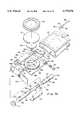
- FIG. 1is a generally perspective, exploded view of one embodiment of the liquid delivery device of the present invention showing an ancillary syringe type device usable for bolus delivery of liquid medication via the bolus injection site of the device.
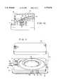
- FIG. 2is a top plan view of the invention shown in FIG. 1 partly broken away to show internal construction.
- FIG. 3is a cross-sectional view taken along lines 3--3 FIG. 2.
- FIG. 4is an enlarged cross-sectional view taken along lines 4--4 of FIG. 2.
- FIG. 5is a greatly enlarged, cross-sectional view taken along lines 5--5 of FIG. 2.
- FIG. 6is an enlarged, cross-sectional view taken along lines 6--6 of FIG. 2.
- FIG. 7is a greatly enlarged, fragmentary view of the liquid delivery port of the device and of the locking tabs for lockably interconnecting a quick connect delivery fitting with the base of the device.
- FIG. 8is a generally perspective, exploded, view of the liquid delivery port of the device and of an infusion set usable with the device.
- FIG. 9is a cross-sectional view of the quick connect delivery fitting shown in FIG. 8.
- FIG. 9Ais an end view of the quick connect fitting shown in FIG. 9.
- FIG. 10is a greatly enlarged cross-sectional view of the area designated as 10 in FIG. 3.
- FIG. 10Ais a generally perspective, illustrative view showing one manner of filling the fluid reservoir of the device.
- FIG. 10Bis a generally perspective, illustrative view showing the device of the invention attached to the patient and showing the patient engage in injecting a bolus dose of liquid medication.
- FIG. 11is a generally perspective, exploded view of an alternate embodiment of the invention.
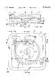
- FIG. 12is a top view of the embodiment shown in FIG. 11 partly broken away to show internal construction.
- FIG. 13is a side elevational, partly cross-sectional view taken along lines 13--13 of FIG. 12.
- FIG. 14is a cross-sectional view taken along lines 14--14 of FIG. 13.
- FIG. 15is a greatly enlarged, fragmentary, cross-sectional view of a portion of the base and cover of the device illustrating the manner in which the distendable membrane and the barrier membrane of the device are sealably clamped between the base and cover.
- FIG. 16is a fragmentary, cross-sectional view of the flow control assembly of the device which is positioned within the base.
- FIG. 17is an enlarged, generally perspective view of the flow control assembly shown in FIG. 16.
- FIG. 18is a front view of yet another form of the fluid delivery device of the invention partly broken away to shown internal construction.
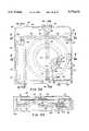
- FIG. 19is a top view of the embodiment shown in FIG. 18 partly broken away to show internal construction.
- FIG. 20is a cross-sectional view taken along lines 20--20 of FIG. 19.
- FIG. 21is a cross-sectional view taken along lines 21--21 of FIG. 19.
- FIG. 21Ais a fragmentary, cross-sectional view taken along lines 21A--21A of FIG. 21.
- FIG. 22is a cross-sectional view taken along lines 22--22 of FIG. 19.
- FIG. 22Ais a cross-sectional view similar to FIG. 22 but showing the fluid being expelled from the fluid reservoir into the body subdermal tissue.
- FIG. 23is a cross-sectional, exploded view of this latest embodiment of the invention.
- FIG. 24is an enlarged, generally perspective, exploded view of the bolus injection port of the device.
- FIG. 25is a generally schematic view illustrating the various modes of operation of the apparatus of the invention.
- FIG. 26is a generally perspective, exploded view of an alternate embodiment of the liquid delivery device of the present invention showing a dispensing and a fill assembly usable for filling the fluid reservoir of the dispensing assembly.
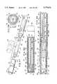
- FIG. 27is a generally perspective, exploded view of one form of the fill assembly of the present invention.
- FIG. 28is an enlarged cross-sectional view of the fill assembly illustrated in FIG. 27 as it appears in the assembled configuration.
- FIG. 29is an enlarged, cross-sectional view taken along lines 29--29 of FIG. 28.
- FIG. 30is a cross-sectional view similar to FIG. 28, but showing the appearance of the component parts of the fill assembly after the plunger of the container has been telescopically moved from a first to a second position.
- FIG. 31is a generally perspective, exploded view of the apparatus of this latest form of the invention showing both the dispensing assembly and the fill assembly in an exploded configuration.
- FIG. 32is a top plan view of the assembled apparatus of the invention shown in FIG. 26 partly broken away to show internal construction.
- FIG. 33is a right-side view of the apparatus shown in FIG. 32.
- FIG. 34is an enlarged, cross-sectional view taken along lines 34--34 of FIG. 32.
- FIG. 35is an enlarged, cross-sectional view taken along lines 35--35 of FIG. 32.
- FIG. 36is a view taken along lines 36--36 of FIG. 35.
- FIG. 37is an enlarged, cross-sectional view taken along lines 37--37 of FIG. 32.
- FIG. 38is an enlarged, cross-sectional view taken along lines 38--38 of FIG. 32.
- FIG. 39is a greatly enlarged, fragmentary view of the liquid delivery port of the device and of the quick connect delivery fitting which is interconnectable with the base of the device.
- FIG. 40is a cross-sectional view taken along lines 40--40 of FIG. 39.
- FIG. 41is an enlarged, generally perspective view of the quick connect delivery fitting showing the locking tabs for lockably interconnecting the fitting with the base of the device.
- the devicecomprises a base 12, having an upper surface 14 including a central convex portion 14a and a peripheral portion 14b circumscribing central portion 14a.
- base 12is also provided with a lower surface 16 to which a patient interconnection means or adhesive pad assembly 18 is connected.
- pad assembly 18functions to releasably interconnect the device to the patient so as to hold it securely in place during the liquid delivery step.
- a stored energy meanscooperates with the upper surface 14 of base 12 to form a reservoir 20 having an inlet port 22 which is in communication with a flow passageway 24 which, in turn, communicates with a filling means shown here as a septum assembly 26 (FIGS. 2, 3, and 4).
- the stored energy meansis here provided in the form of at least one distendable membrane 28 which is superimposed over base 12.
- Membrane 28is distendable as a result of pressure imparted on the membrane by fluids "F" introduced into reservoir 20 through inlet port 22 (FIGS. 2 and 3).
- FIG. 3As membrane 28 is distended in the manner shown in FIG. 3, internal stresses will be established, which stresses tend to move the membrane toward a less distended configuration and in a direction toward base 12.
- Membrane 28can be constructed from a single membrane or from multiple membranes to form a laminate construction of the character shown in FIG. 39 of U.S. Pat. No. 5,279,558, which patent is incorporated herein by reference.
- Membrane 39can be formed from a variety of elastomers of the character discussed in detail in U.S. Pat. No. 5,279,558 (see columns 9 and 10 of the patent).
- ullage defining meansfor providing ullage within the reservoir and for engagement with membrane 28 as the membrane moves toward its less distended starting configuration in the manner shown in FIG. 4.
- the ullage defining means in the embodiment of the invention shown in FIGS. 1 through 10comprises the convex central portion 14a of base 12 and defines an engagement surface for engagement by the distendable membrane as the membrane returns to its less distended configuration.
- fluid contained within the reservoir 20will flow through a fluid passageway 21a formed in the convex central portion 21, the base, and thence uniformly outwardly of the reservoir through an outlet port 32. The fluid will then flow into a fluid outlet passageway 34 via flow control means, the character of which will presently be described.
- Base 12 and cover 40can be constructed from a number of different materials of the character described in U.S. Pat. No. 5,279,558 (see columns 9 and 11).
- the infusion means for infusing medicinal fluids from reservoir 20 into the patientcomprises a tapered outlet cavity 46 formed in base 12 (FIG. 6) which sealably receives a quick connect delivery fitting 48 that comprises a part of the infusion means of the invention.
- Fitting 48includes a tapered inboard end portion 48a and a hexagonally shaped body portion 48b.
- a central bore 50extends through portions 48a and 48b and communicates at its outboard end with a cannula 54 which also forms a part of the infusion means of the invention for infusing liquids into the patient.
- the inboard end of bore 50communicates with fluid passageway 34 when fitting 48 is seated within cavity 46 in the manner shown in FIG. 1.
- locking means shown here as resiliently deformable locking tabs 55are provided on base 12 (FIG. 7). Upon pushing inwardly on fitting 48, tabs 55 will separate so that tapered portion 48a of the fitting can be introduced into cavity 46. As the fitting seats within portion 46, the resiliently deformable locking tabs will close about portion 48b and will engage shoulder 48c in the manner to lockably interconnect the infusion means with the base.
- Filling reservoir 20is accomplished by introducing fluid into the reservoir under pressure via fill means which here comprises a septum assembly 26 mounted in base 12 (FIG. 4).
- Septum assembly 26is of a similar construction to the bolus injection site of the invention, the nature of which will presently be described. More particularly, the septum assembly includes a pierceable septum 26a which is mounted within a tapered cavity 19 formed in base 12. Surrounding septum 26a is a generally circularly shaped guide channel 26b.
- fluidcan be introduced into passageway 24 via a pierceable septum 26a which comprises a part of septum assembly 26.
- distendable membrane 28is distended outwardly in the manner shown in FIGS. 3 and 10 and internal stresses are thereby formed in the membrane which tend to urge it toward its less distended starting configuration.
- a mechanical injection pencan also be used to fill the fluid reservoir.
- distendable membrane 28will provide a constant fluid expelling pressure on the fluid contained within the reservoir throughout the fluid delivery cycle, thereby providing precise delivery of liquid medicament over the prescribed delivery period.
- distendable membrane 28can be tailored to provide the desired fluid flow characteristics. (See for example Column 17 of the patent.)
- fluidwill flow from reservoir 20, through outlet port 32, through the previously identified flow control means and then into outlet passageway 34 (FIG. 10).
- the flow control meanswhich further controls the fluid flow characteristics of the device, here comprises an assemblage 36 which is received in a cavity 61 formed in base 12 and which is preferably constructed from a plurality of stacked members 36a, 36b, and 36c.
- Member 36ais a porous member; member 36b is a rate control element; and member 36c is a porous supporting substrate.
- Member 36ais preferably constructed from a material comprising polysulfone sold by Gelman Sciences under the name and style of "SUPOR”.
- Member 36cis preferably constructed from a porous polycarbonate material available from Corning Costar Corporation or from a material sold by DuPont under the name and style KAPTON which has been laser drilled or machined to provide appropriate flow orifices.
- Member 36ccan be constructed from a porous polypropylene.
- bolus injection meanswhich here comprises a bolus injection site mounted in cover 40 and base 12 and generally designated by the numeral 65.
- this novel bolus injection meansincludes a tapered cavity 67 provided in base 12 within which a pierceable septum 70 is mounted.
- a peripheral groove, or guide channel, 72is provided in cover 40 and surrounds septum 70.
- Septum 70is accessible via an opening provided in cover 40 and channel 72 is specially designed to guidably receive a first skirt portion 74a of a novel adapter means or adapter assembly 74 which also comprises a part of the bolus injection means of the invention.
- Adapter assembly 74includes a central body portion 74b which supports a double-ended hollow needle 76.
- needle 76has a pierceable point 76a at one end and a pierceable point 76b at the other end.
- a second internally threaded skirt portion 74cextends from central body portion 74b and surrounds end 76a of needle 76.
- second skirt portion 74cis specially designed to be threadably interconnected with the threaded barrel portion "B" of a syringe shown here as a dose indicating injection pen "IP" of the character disclosed in U.S. Pat. No. 5,226,896 issued to Harris. While any type of conventional syringe assembly having an injection needle can be used to provide the bolus dose via septum 70, the apparatus of the present form of the invention is specially well suited for use with the Harris injection pen. For this reason, the Harris U.S. Pat. No. 5,226,896 is hereby incorporated by reference as through fully set forth herein.
- second skirt 76c of the adapter assemblyis first threadably connected to barrel "B" of the Harris device. During this step, end 76a of the needle will pierce the septum of a medicament vial disposed within the device IP.
- the adapter assemblyis mated with cover 40 by inserting first skirt 74a into groove 72 and then pressing inwardly on the pen to cause needle end 76b to pierce septum 70. This places the bore of the hollow needle in communication with the passageway 34 formed in base 12 and also in communication with bore 50 of fitting 48 of the infusion means. Operation of the injection pen "IP" in the manner described in U.S. Pat. No. 5,226,896 will then cause a bolus dose to enter the infusion means for delivery to the patient.
- the patientcan receive from liquid reservoir 20 a selected basal dose of insulin of, by way of example, one-half milliliter over a 24 hour period.
- a bolus injection of a predetermined volumecan quickly and easily be accomplished through use of the bolus injection means of the invention thereby appropriately supplementing the basal dose being delivered from the fluid reservoir 20.
- a bolus dosecan be introduced into fluid passageway 34 via septum 70. Because of the resistance to upstream flow offered by the rate control means, the bolus dose will flow through passage 34 toward the central bore 50 of quick connect fitting 48 and thence into delivery line 54. Interconnected with line 54 is a soft cannula assembly 80 (FIG. 8), the operation of which is well understood by those skilled in the art.
- the cannula insertion assembly 82which includes a trocar 82a can be removed, leaving the soft cannula 80a in position within the patient.
- Needle cannula interconnect 84a of the connector assembly 84 of the infusion setcan then be inserted into assembly 80 and interconnect therewith using the conventional latch mechanism 85.
- Connector assembly 84which also forms a part of the infusion means, when connected to assembly 80, places soft cannula 80a in fluid communication with reservoir 20.
- the infusion set of this form of the inventionwhich comprises line 54, connector assembly 84, and soft cannula assembly 80, is of a character well known in the art and is readily available from several commercial sources including Pharma-Plast International A/S of Lynge, Denmark.
- the injection pen IPcan effectively be used to provide the bolus dose delivery when the device of the invention is affixed to the patient's body as, for example, a location proximate the patient's waist. Due to the novel design of the skirt portion 74a of the adapter assembly 74, the injection pen can be easily mated with device 10 by simply inserting the skirt portion into the circular guide channel or groove 72.
- the injection pen IPcan also be conveniently used to fill the fluid reservoir of the device via filling septum 26a while being held in the user's hand.
- skirt portion 74ais guidably received within guide channel 26b formed as a part of septum assembly 26 (see also FIG. 4).
- FIGS. 11 through 17still another form of the fluid delivery device of the invention is there shown and generally designated by the numeral 90.
- this latest embodiment of the inventionis similar in some respects to that shown in FIGS. 1 through 10. Accordingly, like numbers are used to describe like components.
- this latest embodiment of the inventionis unique in that it includes dual reservoirs which communicate with the infusion means of this latest embodiment of the invention.
- the embodiment of the invention there showncomprises a base 92 having an upper surface 94 including a central portion 94a and a peripheral portion 94b circumscribing central portion 94a.
- Base 92is also provided with a lower surface 96.
- Formed within base 92is a fluid passageway 100 (FIG. 12), which communicates with a tapered wall, cavity 102 provided in base 92, which cavity sealably receives portion 104a of a quick connect delivery fitting assembly 104 which is somewhat similar to fitting 48 as previously described.
- the apparatus shown in FIGS. 11 through 17includes stored energy means for forming, in conjunction with the base 92, a pair of reservoirs 106 and 108 having outlets 110 and 112 respectively (FIG. 13).
- outlet 110is in communication with a first inlet passageway 114 leading to passageway 100
- outlet 112is in communication with a second inlet passageway 116 leading to passageway 100.
- Filling of central or inner reservoir 106is accomplished via fill means here comprising a first septum assembly 118 while filling of outer or toroidal reservoir 108 is accomplished via a second fill means or second septum assembly 120.
- Both septum assembliesinclude a pierceable septum 119 (FIG. 14) which is pierceable by a needle of a conventional syringe.
- the stored energy meansis provided in the form of at least one distendable membrane 122 which is superimposed over base 92.
- An ullage defining meansis disposed within a central chamber portion 124 formed in a cover 126 for forming ullage within the chamber.
- an ullage defining meansis disposed within a peripheral chamber portion 130 formed in cover 126 each of the central chambers for forming ullage within the toroidal chamber.
- the ullage meansinteract with membrane 122 which, after being distended, will tend to return to its less distended configuration.
- the ullage defining means of this latest embodiment of the inventioncomprises conformable masses 134 and 136 which uniquely conform to the continuously changing shape of the distendable membrane as the membrane tends to return to its less distended configuration.
- the first conformable mass 134is disposed within chamber 124, while the second conformable mass 136 is disposed within chamber 130.
- the ullage defining means, or flowable masses 134 and 136are preferably constructed from materials such as gels, foams, fluids and soft elastomers. More particularly, materials particularly well suited for constructing the conformable masses include oil, gaseous materials, various polymers and various viscous liquids. Additionally, those masses can be formed from sodium palmitate, sodium sterate and methyl cellulose. Where, as is here the case, the conformable ullage comprises a gel, a yieldable encapsulation barrier means or membrane 140 is used to encapsulate the conformable masses 134 and 136 between the distendable membrane and the barrier membrane. With this construction, the conformable ullages are located between the barrier membrane 140 and the distendable membrane 122. Barrier membrane 140 can be constructed from various materials including polyurethane, polypropylene, polyethylene and fluorosilicon.
- the peripheral portion of the cover 126is provided with a capture groove 142 and an adjacent tongue 144.
- base 92is provided with tongue 146 which mates with groove 142 as the cover moves into engagement with base 92.
- Base 92is further provided with an upstanding membrane cutting means, or protuberance 147 which functions to cleanly cut the stored energy means and barrier membrane 140 upon cover 126 being brought into pressural engagement with base 92.
- central reservoircan be filled via septum assembly 118 and passageway 118a using a conventional fluid containing syringe assembly having needle adapted to penetrate septum 119 of septum assembly 118.
- toroidal reservoir 108can be filled via septum assembly 120 and passageway 120a using a second syringe assembly containing a second fluid either the same as or different from the first fluid used to fill chamber 106. Fluids flowing into the reservoirs are filtered by filter means shown in FIG. 14 as filter elements 157. With the chambers filled, and the quick connect delivery fitting assembly 104 connected to base 92, the device is in condition for the liquid delivery step. As seen in FIG.
- the quick connect delivery fitting assemblyis of slightly different construction, as is the outlet port assembly of the device. More particularly, the outlet port housing 154, within which tapered portion 102 is formed, extends outwardly from the base and is provided with a circumferentially extending locking groove 156 which forms a part of the infusion set locking means of this form of the invention.
- Fitting assembly 104also includes a pair of spaced-apart locking arms 158 which terminate at their inboard ends in hook-like extremities 158a which are receivable within groove 156. By pressing inwardly on the rearwardly extending portions 158b of arms 158, extremities 158a will pivot about a collar 158c carried by the fitting and will resiliently spread apart to permit their release from normal biased engagement with groove 156.
- the base of the deviceis provided with a suitable adhesive to enable the device to be removably affixed to the patient's body such as to the arm or leg of the patient.
- first or central chamber 106 and within toroidal chamber 108will be urged to flow through fluid passageway 100 as the stored energy means, or distendable membrane 122 tends to return to its less distended configuration.
- the conformable ullages contained within the reservoirswill closely conform to the changing geometry of the stored energy means as the stored energy means moves toward base 92.
- the flow control meanshere comprises a pair of assemblies each being of the character shown in FIG. 17. Each assembly is receivable within a cavity provided in the base. More particularly, assemblage 160 is mounted within a cavity 162 provided in the central portion of the base while assembly 164 is mounted within a cavity 166 provided in the peripheral portion of the base. As shown in FIG. 17, each assemblage 160 and 164 is of a laminate construction comprising filtering means for filtering the fluid flowing outwardly of the reservoirs and rate control means for controlling the rate of fluid flow from the reservoirs into passageway 100. Referring to FIG. 17, it can be seen that the filter means comprises disk-like filter element 160a while the rate control element comprises a disk-like rate control element 160b.
- a porous disk-like support substrate 160cprovides support to elements 160a and 160b.
- the assemblage comprising filter element 160a, rate control element 160b and porous substrate 160cis supported in base 92 in the manner shown in FIG. 16.
- Filter element 160acan be constructed from a wide variety of materials. However, a material comprising polysulfone sold by Gelman Sciences under the name and style of SUPOR has proven satisfactory.
- Rate control element 160bis preferably constructed from a polycarbonate material having extremely small flow apertures ablatively drilled by an excimer laser ablation process. Both the orifice size and unit distribution can be closely controlled by this process. However, a number of other methods can also be used to construct this element.
- Porous substrate 160ccan similarly be constructed from various materials such as a porous polypropylene available from Gelman Sciences.
- the latest embodiment of the inventionalso includes bolus injection means comprising a bolus injection site 65, which is identical in construction and operation to that previously described.
- the bolus injection meansincludes a pierceable septum 70 which is accessible through the cover of the device and also includes a guide channel 72 which permits easy mating of the previously described adapter assembly 74.
- liquids introduced via septum 70will flow into a passageway 100a which communicates with outlet passageway 100, thereby permitting delivery to the patient of bolus doses of medication via the infusion means of the device.
- FIGS. 18 through 24yet another form of the fluid delivery device of the invention is there shown and generally designated by the numeral 170.
- the devicehere comprises a base 172, having an upper surface 174 including a central portion 174a and a peripheral portion 174b circumscribing central portion 174a.
- base 172is also provided with a lower surface 176 to which a patient interconnection means or adhesive pad assembly 178 is connected.
- pad assembly 178functions to releasably interconnect the device to the patient so as to hold it securely in place during the delivery step.
- a stored energy meanscooperates with the upper surface 174 of base 172 to form a reservoir 180 having an inlet port 182 which is in communication with a flow passageway 184 which, in turn communicates with a filling means shown here as a septum assembly 186 (FIGS. 18, 19, and 20).
- the stored energy meansis here provided in the form of at least one distendable membrane 188 which is superimposed over base 172.
- Membrane 188is distendable as a result of pressure imparted on the membrane by fluids "F" introduced into reservoir 180 through inlet port 182 (FIG. 20). As membrane 188 is distended in the manner shown in FIG.
- Membrane 188is substantially identical to membrane 28 (FIG. 3) and can be constructed from a single membrane or from multiple membranes to form a laminate construction.
- ullage defining meansfor providing ullage within the reservoir and for engagement with membrane 188 as the membrane moves toward its less distended starting configuration.
- the ullage defining means provided in this latest embodiment of the inventioncomprises a conformable mass 190 which is engageable by the distendable membrane as the membrane returns to its less distended configuration.
- Conformable mass 190is of a character similar to the conformable masses that make up the ullage defining means of the form of the invention shown in FIGS. 11 through 17.
- fluid contained within the reservoir 180will flow uniformly outwardly of the reservoir through an outlet port 180a and into a fluid outlet passageway 230 via flow control means generally designated by the numeral 224 (FIG. 22A).
- cover meansSuperimposed over base 172 is the cover means, shown here as a rigid cover 200, which functions, through the use of novel sealing means, to sealably enclose membrane 188.
- the sealing meanshere comprises a circular groove 175 formed in peripheral surface 174b of base 172 and a circular rim like protuberance 200a formed on the lower surface of cover 200.
- Protuberance 200ais receivable within groove 175 and functions to sealably clamp distendable membrane 188 between the cover and the base in the manner shown in FIGS. 20 and 22.
- a medicament and use label 41can be affixed to cover 200 in the manner previously described and as shown in FIG. 1.
- base 172 and cover 200can be constructed from a variety of materials of the character described in U.S. Pat. No. 5,279,558.
- the infusion means of this latest form of the invention for subdermal infusion of medicaments into the patientis of a highly novel construction. More particularly, the infusion means here comprises a circuitous shaped hollow cannula 206 which is carried within a circuitous channel 208, formed in the intermediate body portion 172i of base 172.
- Cannula 206includes a body portion 206a which is mounted within channel 208 and also includes an outlet end 206b, here provided in the form of a needle-like segment, which extends generally perpendicularly downward from the lower surface of base 172.
- circuitous body portion 206a, of the cannulawhen mounted within channel 208, provides an extremely strong and rigid structure that effectively prevents bending or breakage of the small diameter cannula. So that outlet end 206b can easily penetrate the patient's skin and tissue "ST" for subdermal penetration (see FIG. 22A), end 206b is provided with a sharp, pointed extremity 206c (FIGS. 22 and 22A).
- a protective cover assembly 210surrounds these portions of the cannula.
- the skirt portion 210a of the protective cover 210can be readily separated from the base by breaking it away along a serration line 211 formed between the skirt portion 210a and a disk like base portion 210b.
- Skirt portion 210ais configured to receive a plug 210p which provides a sterile barrier and prevents premature fluid flow from end 206c of the cannula.
- Base portion 210bis provided with an upstanding circumferentially extending rim 210c which is receivable within a cylindrically shaped cavity 214 provided in base 172 (see FIG. 22). Disk-like base portion 210b is also receivable within an aperture 178a provided in pad assembly 178 (FIG. 23).
- Filling of reservoir 180is accomplished by introducing fluid into the reservoir under pressure via a septum assembly 186 which is mounted in base 172 (FIG. 18).
- a septum assembly 186which is mounted in base 172 (FIG. 18).
- fluidcan be introduced into passageway 184 via a pierceable septum 186a which comprises a part of septum assembly 186.
- a barrier means or barrier membrane 217is distended outwardly against the conformable mass 190 controllably moving it along with a distendable membrane 188 toward cover 200.
- distendable membrane 188will engage surface 219 formed in cover 200, and the ullage defining means will uniquely conform to surface 219 as well as to the varying shape of distendable membrane 188.
- any gases contained within the reservoirwill be vented to atmosphere via vent means, shown here as a vent plug 221.
- Barrier membrane 217can be constructed from the various materials previously described.
- the conformable ullageWhen the fluid is dispensed from the device, the conformable ullage will permit the distendable membrane to provide a constant fluid expelling pressure on the fluid contained within the reservoir throughout the fluid delivery cycle, thereby avoiding undesirable delivery rate tail off at the end of the delivery period.
- This novel substantially linear performancepermits the device to meet even the most stringent of delivery protocols.
- fluidwill flow from reservoir 180, through outlet port 192, through the flow control means, and then, in a manner presently to be described, into cannula 206.
- the flow control means of this latest form of the inventioncomprises an assemblage 224 which is received in a cavity 225 formed in the high novel fusion means of the present invention, the character of which will presently be described.
- Assemblage 224comprises a first wafer 224a which functions as a filter means of the character previously described.
- Wafer 224bis preferably constructed from a hydrogel rate control medium which, upon imbibing fluid, swells into a cavity provided in the filter. Upon swelling into a known configuration, wafer 224b will function to provide a specific permeability thereby precisely controlling the rate of fluid flow from the reservoir 180.
- Wafer 224cfunctions as a support substrate for the assemblage.
- This infusion meansincludes the previously identified circuitous shaped cannula 206, the inlet end 206i of which is connected to a hollow housing 226 that is mounted in base 172 in the manner best seen in FIG. 21.
- Inlet end 206i of the cannulacommunicates with a chamber 226a formed in housing 226 as does the outlet end 230a of a hollow tube 230.
- the inlet end 230b of tube 230is connected to a second hollow housing 232 which is mounted in base 172 and within which the previously identified cavity 225 is formed.
- tube 230places the outlet 180a of reservoir 180 in fluid communication with chamber 226a of housing 226 and also in fluid communication with cannula 206 via an inlet port 234 which is disposed within chamber 226a. Accordingly, fluid can flow from reservoir 180 into chamber 225 via the flow control means, then into tube 230 and finally into cannula 206 for subdermal delivery to the patient.
- a bolus injection meanswhich here forms a part of the infusion means of the invention and includes a bolus injection site which is accessible through cover 200.
- this novel bolus injection meansis similar to that previously described but includes the earlier identified hollow housing 226 within which a pierceable septum 236 is mounted in the manner shown in FIG. 21. Septum 236 is held in place within cover 200 by a retainer cap 237. A peripheral groove 238 surrounds retainer cap 237 and is specifically designed to receive the first skirt portion 74a of the previously described adapter means or adapter assembly 74.
- Adapter assembly 74is of identical construction and operation to that described in connection with the embodiment of the invention shown in FIGS. 1 through 10 and serves to deliver a bolus dose of medicinal fluid into chamber 226a of hollow housing 226 and thence into cannula 206 via inlet 234.
- adapter assembly 74is specially designed to be threadably interconnected with the dose indicating injection pen "IP" of the character disclosed in U.S. Pat. No. 5,226,896 issued to Harris.
- the patientcan continually receive a selected basal dose of liquid medication, such as insulin from reservoir 180.
- a basal dose of liquid medicationsuch as insulin from reservoir 180.
- a bolus injection of a predetermined volumecan quickly and easily be administered through use of the novel bolus injection means of the invention and in this way appropriately supplement the basal dose being delivered from reservoir 180.
- FIG. 25several fluid delivery regimens are there illustrated.
- a fluid delivery device 250having a fluid reservoir 252 with a volume V-1 is used to accomplish delivery of a liquid medicament such as insulin.
- the medicamentis delivered to the patient through an appropriate infusion means which includes a delivery line 253 and a flow rate control means designated as R-1.
- Reservoir 252can be filled using a filling means here shown as a septum assembly S-1.
- medicinal liquidscan be delivered to the patient at a fixed rate over time with the rate of delivery being governed by the character of the flow rate control means R-1.
- a fluid delivery device 254 having a fluid reservoir 252 with a volume V-1is there shown.
- fluidcan be delivered to the patient at a basal rate via a delivery line 255 and a flow rate control means designated as R-1.
- Reservoir 252can, once again, be filled by a fill means shown here is a septum assembly S-1.
- a bolus dose delivery meansgenerally designated as S-2. This bolus dose delivery means, which can be of the character illustrated and described in connection with the embodiment of the invention shown in FIGS.
- Device 254exemplifies the types of single reservoir devices of the invention illustrated in FIGS. 1 through 10 and in FIGS. 18 through 24 of the drawings.
- a delivery device 256is there provided. Unlike delivery devices 250 and 254, device 256 includes dual fluid reservoirs 252 and 258. As before, reservoir 252 has a volume V-1, while second reservoir 258 has a volume V-2. Reservoir 252 can be filled by septum assembly S-1 while reservoir 258 can be filled using a septum assembly S-2. Reservoir 252 communicates with the patient via a delivery line 257 and a first flow rate control means R-1, while reservoir 258 communicates with the patient via a delivery line 259 and a second flow rate control means designated as R-2. For reasons presently to be described, this arrangement is ideally for delivering liquid medicaments such as insulin.
- insulincan be delivered to the patient via delivery line 261 with insulin flowing simultaneously from both reservoirs 252 and 258.
- the amount of fluid being delivered from each of the reservoirsis, of course, determined by the character of the flow rate control device which is interconnected with that reservoir.
- insulincan be delivered to the patient at a prescribed basal delivery rate from reservoir 258 throughout the entire nighttime hours.
- a single dual reservoir fluid delivery devicecan be used to provide a precise basal delivery of insulin to the patient over an entire 24-hour period.
- a bolus dose delivery meansdesignated as S-3.
- This important bolus delivery meanspermits the patient to introduce into delivery line 261 via S-3 a bolus dose of insulin at any time the patient discovers that his or her blood sugar level is too high.
- this latest arrangement as shown in FIG. 25,is exemplified by the dual reservoir embodiment of the invention which is illustrated in FIGS. 11 through 17 of the drawings.
- FIGS. 26 through 41yet another form of the apparatus of the present invention is there illustrated.
- the apparatushere comprises two main assemblies, namely a fluid delivery assembly 300 (FIGS. 26 and 31) and a fill assembly 302 (FIG. 27 through 30) which can be operably mated with the fluid delivery assembly in a manner presently to be described.
- Fluid delivery assembly 300the details of construction of which will presently be described, is similar in some respects to the fluid delivery devices previously described herein and includes a base 304 having an upper surface 306 including a central portion 306a and a peripheral portion 306b (FIG. 31).
- the fill assembly portion 302 of the apparatuscomprises a container subassembly 308, an adapter subassembly 310, and a cover subassembly 312, the character of which will presently be described.
- Container subassembly 308includes a body portion 314, having a fluid chamber 316 for containing an injectable fluid "F" which is provided with first and second open ends 318 and 320 (FIGS. 28 and 30).
- First open end 320is sealably closed by closure means here provided in the form of a pierceable septum assembly 322.
- Septum assembly 322is held securely in position by clamping ring 324.
- a plunger 326is telescopically movable within chamber 316 of container subassembly 308 from a first location shown in FIG. 28 where it is proximate open end 318 to a second position shown in FIG. 30 where it is proximate open end 320.
- the vial portion of the container subassemblycan be constructed of various materials including glass and plastic.
- the adapter subassembly 310comprises a hollow housing 330 having a first open end 332 and a second closed end 334 (FIG. 30).
- Container subassembly 308is telescopically receivable within open end 332 of housing 330 in the manner shown in FIG. 28 so that the housing can be moved from the first extended position shown in FIG. 28 to the vial encapsulation position shown in FIG. 30.
- pusher meansshown here as an elongated pusher rod 336 which functions to move plunger 326 within fluid chamber 316 from the first position shown in FIG. 28 to the second position shown in FIG. 30.
- pusher rod 336has a first end 336a interconnected with a closure wall 334 of housing 330 and an opposite end 336b which engages plunger 326 and causes telescopic movement of the plunger within chamber 316 of container subassembly 308 as housing 330 is moved from the extended position into the vial encapsulating position shown in FIG. 30.
- the interior wall 330a of housing 330is provided with circumferentially spaced-apart protuberances 340 which engage and center container subassembly 308 within housing 330. Due to the small surface area presented by protuberances 340, there is little frictional resistance to the sliding movement of container subassembly 308 relative to housing 330 as the housing is moved from the extended position shown in FIG. 28 into the vial encapsulating position shown in FIG. 30.
- cover subassembly 312 of the fill assembly of the present form of the inventionincludes a spiral wound, frangible portion 342 having a first open end 342a for telescopically receiving body portion 314 of container subassembly 308 (FIG. 28) and a second closed end 342b.
- Portion 342initially circumscribes a major portion of container subassembly 308 in the manner best seen in FIG. 28.
- An integral pull tab 344is provided to permit the spiral wound, frangible portion to be pulled from container subassembly 308 so as to expose a substantial portion of body 314. As best seen in FIGS.
- a medicament label 346circumscribes spiral wound portion 342 and serves to prevent accidental unwinding of the spiral portion from the container subassembly 308. However, upon pulling tab 344, the spiral portion will unwind and, in so doing, will tear medicament label 346 so that the spiral portion 342 of the covering as well as the cylindrical portion 348 which, also comprises a part of the cover assembly, can be slipped from the container subassembly 308 so as to expose to view septum assembly 322 (FIG. 30).
- end 342b of cylindrical portion 348 of subassembly 312is provided with venting apertures 350 which are covered by a porous vent patch 352 which can be constructed from any suitable porous material that will permit air entrapped within the interior of cover subassembly 312 to be expelled to atmosphere as the subassembly is placed over container subassembly 308.
- the fluid delivery assembly 300 of the apparatus of the inventioncan be seen to include the previously identified base 304 which defines upper surface 306.
- a flexible barrier meansshown here as a barrier membrane 354, cooperates with the upper surface 306 of the base to form a reservoir 356 having an inlet/outlet port 358 which is in communication with flow passageways 360 and 362 the latter of which, in turn communicates with a cannula 364, the purpose of which will presently be described. (See FIGS. 31 and 35).
- a stored energy meansis here provided in the form of at least one distendable membrane 366 which is superimposed over barrier membrane 354 and base 304. Disposed between barrier membrane 354 and distendable membrane 366 is an ullage defining means, shown here as a conformable mass 388 (FIG. 35).
- Conformable mass 388is of a character similar to the conformable masses that make up the ullage defining means of the form of the invention shown in FIGS. 11 through 17 and can comprise a gel or other deformable material.
- Membrane 354is distendable as a result of pressure imparted on the membrane by fluids "F" introduced into reservoir 356 through port 358. As membrane 354 is distended in the manner shown in FIG. 35, it will act on the conformable ullage, which will, in turn, act upon distendable membrane 366 causing internal stresses to be established, which stresses tend to move the membrane toward a less distended configuration and in a direction toward surface 306a of base 304.
- membrane 354can be constructed from a single membrane or from multiple membranes to form a laminate.
- fluid contained within the reservoir 356will flow uniformly outwardly of the reservoir through passageway 360 and then into a fluid outlet chamber 390 (FIG. 35) via flow control means generally designated by the numeral 392.
- sealing meansSuperimposed over the central portion 306a of the base is sealing means, shown here as a sealing ring 396, which functions to sealably interconnect membrane 366 with base 304.
- Ring 396includes a circular groove 396a within which is received a circular rim like protuberance 400 formed on the upper surface of base 304 (FIG. 35).
- Protuberance 400is closely received within groove 396a and functions to sealably clamp distendable membrane 366 between the clamping rings and the base in the manner shown in FIGS. 35 and 38.
- the periphery 354a of barrier membrane 354is sealably affixed to the base by any suitable means, such as adhesive or thermal bonding.
- base 304 and clamping ring 396can be constructed from a variety of materials of the character described in U.S. Pat. No. 5,279,558.
- a unique feature of the base assembly of this latest form of the inventioncomprises, along one side of base 304, an elongated receiving chamber 404 which is adapted to receive a portion of the fill assembly of the invention.
- Receiving chamber 404is formed within a generally cylindrically shaped housing 406 which is integrally formed with one of marginal portions 306b of the base.
- the previously identified piercing cannula 364extends into the inboard portion of receiving chamber 404 and functions to provide a fluid flow path between the fill assembly and the fluid reservoir 356.
- the fluid delivery assembly 300further includes a housing 407 having an internal chamber 409 within which the base assembly, including chamber 404, is received.
- An apertured end wall 407asubstantially encapsulates the base assembly within chamber 409.
- End wall 407aincludes an aperture 409a which is indexible with receiving chamber 404 when the base assembly is positioned within housing 407 in the manner shown in FIG. 32.
- Housing 407is also provided with an aperture 410 which aligns with an important feature of the invention, namely a bolus injection means, the character of which will presently be described.
- the cover subassemblyis first removed from the container subassembly by pulling on pull-tab 344. This will cause the spiral portion 342 of the cover subassembly to tear away from the container subassembly so that it can be separated from the forwardly disposed portion 348. Once the spiral wound portion 342 is removed, cylindrical portion 348 can also be removed and discarded. Removal of the cover subassembly to expose the forward portion of the container subassembly and septum 322 readies the adapter subassembly for interconnection with the fluid delivery assembly.
- a closure plug 412which forms a part of the cover subassembly must be removed in the manner illustrated in FIG. 26.
- the container subassembly 308can be telescopically inserted into receiving chamber 404 and pushed forwardly in the direction indicated by the arrow 314 in FIG. 34.
- a force exerted in the direction of the arrowwill cause the adapter subassembly to move to the right as viewed in FIG. 34 and will cause the piercing cannula 364 to pierce septum 322.
- Ring 396which is in clamping engagement with base 304, functions to capture and seal the distendable membrane relative to the base.
- the periphery of the barrier member 354is sealably affixed to the base as by adhesive or thermal bonding, so as to prevent leakage of fluid around the perimeter of the member.
- inlet means shown here as an inlet 417 formed in base 304is provided to enable the introduction of gel which forms the conformable ullage 388 of this embodiment of the invention.
- Inlet 417communicates with a fluid passageway 419 which, in turn, communicates with the volume defined between the under surface of membrane 366 and the upper surface of barrier member 354 via an inlet port 419a.
- Inlet 417is sealably closed by a bonded plug 421.
- the conformable mass 388which comprises the ullage defining means of the invention is in direct engagement with distendable membrane 366 which, after being distended, will tend to return to its less distended configuration.
- shape of the conformable ullagewill continuously vary as the distendable membrane distends outwardly from the base during reservoir filling and then tends to return to its less distended configuration during fluid delivery.
- the conformable ullage, or mass 388is here constructed from a flowable gel
- the conformable ullagecan also be constructed from a number of materials such as various types of foams, fluids and soft elastomers.
- the conformable ullagemay comprise an integral conforming mass.
- an encapsulation barrier membersuch as member 354 must be used to encapsulate the gel or fluid and to provide an appropriate interface to the fluid contained in the reservoir.
- a separate pliable filmcan be used to encapsulate the gel or other fluid medium.
- reservoir 356Once reservoir 356 is filled with fluid from the container subassembly of the fill assembly, the fluid will remain in the reservoir until such time as an outlet flow path of the fluid delivery assembly is opened. Once this path is opened in a manner presently to be described, distendable membrane 366 will tend to return to its less distended configuration and will act upon the conformable ullage 388 and the barrier member 354 in a manner to cause fluid to flow from reservoir 356 outwardly through flow passageways 360 and 362 and then into chamber 390 via the flow control means 392 (FIG. 35).
- base portion 406 and adapter member 330include locking means for locking the adapter member 330 within receiving chamber 404 after the fill subassembly has been mated with the fluid delivery device.
- These locking meansare here provided in the form of a series of forwardly and rearwardly disposed locking teeth 420 and 422 respectively formed on adapter 330 and a locking tab 424 formed on base portion 406. As indicated in FIG. 34, these locking teeth are constructed so that they will slide under the flexible locking tab 424, which is provided proximate the entrance of receiving chamber 404, as the adapter subassembly is urged inwardly of receiving chamber 404.
- this viewing meanstakes the form of an elongated viewing window 428 which is provided in housing 330 (FIG. 27).
- the body portion 308 of the container subassemblyis provided with a plurality of longitudinally spaced-apart index lines, or marks 430, which can be viewed through window 428.
- Index lines 430provide reference points for observing the volume of fluid remaining within the container subassembly.
- a protuberance 330a formed on housing 330 in cooperation with channel 406afunctions to provide polarized orientation of the subassembly as it is introduced into receiving chamber 404.
- the delivery means for delivering medicinal fluids from reservoir 356 outwardly of the devicecomprises a tapered outlet cavity 433 which is formed in base 304 and defines outlet chamber 390. Cavity 433 is adapted to receive a quick connect delivery fitting 435 that comprises a part of the delivery means of the invention.
- Fitting 435includes a tapered inboard end portion 435a and a body portion 435b.
- a central bore 437extends through portions 435a and 435b and communicates at its outboard end with a cannula 450 which also forms a part of the delivery means of the invention for delivering fluids from the device.
- the inboard end of bore 437communicates with the chamber and with a stub passageway 452 which houses a portion of the flow control means 392.
- locking means shown here as resiliently deformable locking tabs 454are provided on the body portion of fitting 435. Tabs 454 lockably engage a locking surface 455 provided on cover 407 (FIG. 40). Upon pushing inwardly on fitting 435, tabs 454 will yieldably deform inwardly so that tapered portion 435a of the fitting can be introduced into chamber 390. As the fitting seats within the chamber, the resiliently deformable locking tabs will spring outwardly and engage locking surface 455 in a manner to lockably interconnect the delivery means with the cover 407.
- the flow control meanswhich further controls the fluid flow characteristics of the device, here comprises an assemblage 392 which is preferably constructed from a plurality of components 392a, 392b, and 392c.
- Member 392ais a porous member; member 392b is a rate control element; and member 392c is a porous supporting substrate.
- Member 392ais preferably constructed from a material comprising polysulfone sold by Gelman Sciences under the name and style of "SUPOR".
- Member 392bis preferably constructed from a porous polycarbonate material available from Corning Costar Corporation or from a material sold by DuPont under the name and style KAPTON which has been laser drilled or machined to provide appropriate flow orifices. Member 392c can be constructed from a porous polypropylene. After flowing through the flow control means, the liquid medicament will flow outwardly of the device via delivery cannula 450.
- bolus injection meanswhich here comprises a bolus injection site mounted in base 304 and accessible through aperture 410 provided in cover 407.
- this novel bolus injection meansincludes a cavity 460 provided in base 304 within which a pierceable septum assembly 462 is mounted.
- Assembly 462includes a pierceable septum 464 and a retaining ring 466.
- Septum 464is accessible via opening 410 provided in cover 407 and is specially designed to accept a needle "N" of a conventional syringe (see FIG. 37).
- a bolus dosecan be conveniently introduced into a fluid passageway 467 formed in base 304 via septum 464.
- the bolus dosewill then flow through passage 452 and toward the central bore 437 of quick connect fitting via the flow control means. After passing through the flow control means, the bolus dose will flow into delivery cannula 450.
- the patientcan continually receive a selected basal dose of liquid medication, such as insulin from reservoir 356.
- a basal dose of liquid medicationsuch as insulin from reservoir 356.
- a bolus injection of a predetermined volumecan quickly and easily be administered through use of the novel bolus injection means of the invention and in this way appropriately supplement the basal does being delivered from reservoir 356.
Landscapes
- Health & Medical Sciences (AREA)
- Engineering & Computer Science (AREA)
- Animal Behavior & Ethology (AREA)
- General Health & Medical Sciences (AREA)
- Biomedical Technology (AREA)
- Heart & Thoracic Surgery (AREA)
- Hematology (AREA)
- Life Sciences & Earth Sciences (AREA)
- Veterinary Medicine (AREA)
- Anesthesiology (AREA)
- Public Health (AREA)
- Vascular Medicine (AREA)
- Chemical & Material Sciences (AREA)
- Bioinformatics & Cheminformatics (AREA)
- Medicinal Chemistry (AREA)
- Infusion, Injection, And Reservoir Apparatuses (AREA)
Abstract
Description
Claims (25)
Priority Applications (10)
| Application Number | Priority Date | Filing Date | Title |
|---|---|---|---|
| US08/606,090US5779676A (en) | 1995-10-11 | 1996-02-23 | Fluid delivery device with bolus injection site |
| AU75162/96AAU719738B2 (en) | 1995-10-11 | 1996-10-11 | Fluid delivery device with bolus injection site |
| PCT/US1996/016361WO1997013544A1 (en) | 1995-10-11 | 1996-10-11 | Fluid delivery device with bolus injection site |
| EP96937679AEP0957955A1 (en) | 1995-10-11 | 1996-10-11 | Fluid delivery device with bolus injection site |
| CA002234581ACA2234581A1 (en) | 1995-10-11 | 1996-10-11 | Fluid delivery device with bolus injection site & fill assembly |
| JP51524997AJP2001515371A (en) | 1995-10-11 | 1996-10-11 | Drug delivery device with bolus injection site |
| BR9610764ABR9610764A (en) | 1995-10-11 | 1996-10-11 | Fluid dispensing device with bolus injection |
| US08/991,122US5921962A (en) | 1995-10-11 | 1997-12-16 | Fluid delivery device with flow indicator and rate control |
| US08/991,123US5957891A (en) | 1995-10-11 | 1997-12-16 | Fluid delivery device with fill adapter |
| US09/312,590US6277095B1 (en) | 1995-10-11 | 1999-05-14 | Fluid delivery device with full adapter |
Applications Claiming Priority (2)
| Application Number | Priority Date | Filing Date | Title |
|---|---|---|---|
| US08/541,184US5776103A (en) | 1995-10-11 | 1995-10-11 | Fluid delivery device with bolus injection site |
| US08/606,090US5779676A (en) | 1995-10-11 | 1996-02-23 | Fluid delivery device with bolus injection site |
Related Parent Applications (1)
| Application Number | Title | Priority Date | Filing Date |
|---|---|---|---|
| US08/541,184Continuation-In-PartUS5776103A (en) | 1995-10-11 | 1995-10-11 | Fluid delivery device with bolus injection site |
Related Child Applications (2)
| Application Number | Title | Priority Date | Filing Date |
|---|---|---|---|
| US08/991,123Continuation-In-PartUS5957891A (en) | 1995-10-11 | 1997-12-16 | Fluid delivery device with fill adapter |
| US08/991,122Continuation-In-PartUS5921962A (en) | 1995-10-11 | 1997-12-16 | Fluid delivery device with flow indicator and rate control |
Publications (1)
| Publication Number | Publication Date |
|---|---|
| US5779676Atrue US5779676A (en) | 1998-07-14 |
Family
ID=46251804
Family Applications (1)
| Application Number | Title | Priority Date | Filing Date |
|---|---|---|---|
| US08/606,090Expired - Fee RelatedUS5779676A (en) | 1995-10-11 | 1996-02-23 | Fluid delivery device with bolus injection site |
Country Status (1)
| Country | Link |
|---|---|
| US (1) | US5779676A (en) |
Cited By (111)
| Publication number | Priority date | Publication date | Assignee | Title |
|---|---|---|---|---|
| US5957895A (en) | 1998-02-20 | 1999-09-28 | Becton Dickinson And Company | Low-profile automatic injection device with self-emptying reservoir |
| WO1999052509A1 (en)* | 1998-04-15 | 1999-10-21 | Science Incorporated | Fluid delivery device with collapsible needle cover |
| US5993421A (en)* | 1994-12-02 | 1999-11-30 | Science Incorporated | Medicament dispenser |
| US6007518A (en)* | 1995-12-22 | 1999-12-28 | Science Incorporated | Fluid delivery device with conformable ullage and fill assembly |
| WO2001017580A3 (en)* | 1999-09-03 | 2002-01-31 | Science Inc | Fluid delivery device with temperature controlled energy source |
| WO2001089607A3 (en)* | 2000-05-23 | 2002-02-28 | Elan Pharma Int Ltd | Gas driven drug delivery device |
| US6416495B1 (en)* | 2000-10-10 | 2002-07-09 | Science Incorporated | Implantable fluid delivery device for basal and bolus delivery of medicinal fluids |
| US6485461B1 (en) | 2000-04-04 | 2002-11-26 | Insulet, Inc. | Disposable infusion device |
| US6656159B2 (en) | 2002-04-23 | 2003-12-02 | Insulet Corporation | Dispenser for patient infusion device |
| US6656158B2 (en) | 2002-04-23 | 2003-12-02 | Insulet Corporation | Dispenser for patient infusion device |
| US6669669B2 (en) | 2001-10-12 | 2003-12-30 | Insulet Corporation | Laminated patient infusion device |
| US20040015131A1 (en)* | 2002-07-16 | 2004-01-22 | Flaherty J. Christopher | Flow restriction system and method for patient infusion device |
| US20040027083A1 (en)* | 2002-04-26 | 2004-02-12 | Toyoda Koki Kabushiki Kaisha | Motor control device |
| US6692457B2 (en) | 2002-03-01 | 2004-02-17 | Insulet Corporation | Flow condition sensor assembly for patient infusion device |
| US6699218B2 (en) | 2000-11-09 | 2004-03-02 | Insulet Corporation | Transcutaneous delivery means |
| US20040064088A1 (en)* | 2002-09-30 | 2004-04-01 | William Gorman | Dispenser components and methods for patient infusion device |
| US20040064096A1 (en)* | 2002-09-30 | 2004-04-01 | Flaherty J. Christopher | Components and methods for patient infusion device |
| US6723072B2 (en) | 2002-06-06 | 2004-04-20 | Insulet Corporation | Plunger assembly for patient infusion device |
| US20040078028A1 (en)* | 2001-11-09 | 2004-04-22 | Flaherty J. Christopher | Plunger assembly for patient infusion device |
| US20040087894A1 (en)* | 2000-09-08 | 2004-05-06 | Flaherty J. Christopher | Devices, systems and methods for patient infusion |
| US6749587B2 (en) | 2001-02-22 | 2004-06-15 | Insulet Corporation | Modular infusion device and method |
| US20040116866A1 (en)* | 2002-12-17 | 2004-06-17 | William Gorman | Skin attachment apparatus and method for patient infusion device |
| US6768425B2 (en) | 2000-12-21 | 2004-07-27 | Insulet Corporation | Medical apparatus remote control and method |
| US20040153032A1 (en)* | 2002-04-23 | 2004-08-05 | Garribotto John T. | Dispenser for patient infusion device |
| US6830558B2 (en) | 2002-03-01 | 2004-12-14 | Insulet Corporation | Flow condition sensor assembly for patient infusion device |
| US20050014503A1 (en)* | 2000-11-17 | 2005-01-20 | Kabushiki Kaisha Toshiba | Scheme for registration and authentication in wireless communication system using wireless LAN |
| US20050033233A1 (en)* | 2003-08-04 | 2005-02-10 | Kriesel Marshall S. | Infusion apparatus with constant force spring energy source |
| US20050033232A1 (en)* | 2003-08-05 | 2005-02-10 | Kriesel Marshall S. | Infusion apparatus with modulated flow control |
| US20050065760A1 (en)* | 2003-09-23 | 2005-03-24 | Robert Murtfeldt | Method for advising patients concerning doses of insulin |
| US20050070847A1 (en)* | 2003-09-29 | 2005-03-31 | Van Erp Wilhelmus Petrus Martinus Maria | Rapid-exchange balloon catheter with hypotube shaft |
| US20050171477A1 (en)* | 2002-05-23 | 2005-08-04 | Seedlings Life Science Ventures | Apparatus and method for rapid auto-injection of medication |
| US6960192B1 (en) | 2002-04-23 | 2005-11-01 | Insulet Corporation | Transcutaneous fluid delivery system |
| US20050263615A1 (en)* | 2004-05-26 | 2005-12-01 | Kriesel Marshall S | Fluid delivery apparatus with adjustable flow rate control |
| US20050277884A1 (en)* | 2004-05-26 | 2005-12-15 | Kriesel Marshall S | Fluid delivery apparatus with bellows reservoir |
| US20050277883A1 (en)* | 2004-05-26 | 2005-12-15 | Kriesel Marshall S | Fluid delivery device |
| US20050277882A1 (en)* | 2004-05-26 | 2005-12-15 | Kriesel Marshall S | Infusion apparatus |
| US20060106346A1 (en)* | 2004-09-10 | 2006-05-18 | Becton, Dickinson And Company | Reconstituting infusion device |
| US20060122562A1 (en)* | 2004-11-19 | 2006-06-08 | Mckinley Medical L.L.L.P. | Controlled-volume infusion device |
| US20060195057A1 (en)* | 2005-02-18 | 2006-08-31 | Kriesel Marshall S | Fluid delivery apparatus with vial fill |
| US20060196552A1 (en)* | 2005-02-17 | 2006-09-07 | Kriesel Marshall S | Distal rate control device |
| US20060206052A1 (en)* | 2005-02-15 | 2006-09-14 | Kriesel Marshall S | Fluid delivery and mixing apparatus with flow rate control |
| US7169128B2 (en) | 2003-08-04 | 2007-01-30 | Bioquiddity, Inc. | Multichannel fluid delivery device |
| US20070156090A1 (en)* | 2004-05-26 | 2007-07-05 | Kriesel Marshall S | Fluid delivery apparatus |
| US20070219501A1 (en)* | 2006-03-15 | 2007-09-20 | Kriesel Marshall S | Fluid dispensing apparatus |
| US20080009835A1 (en)* | 2005-02-17 | 2008-01-10 | Kriesel Marshall S | Fluid dispensing apparatus with flow rate control |
| US20080027376A1 (en)* | 2006-07-31 | 2008-01-31 | Kriesel Marshall S | Fluid dispensing device with additive |
| US20080243077A1 (en)* | 2007-04-02 | 2008-10-02 | Bivin Donald B | Fluid dispenser with uniformly collapsible reservoir |
| US20080281271A1 (en)* | 2007-05-09 | 2008-11-13 | Griffiths Steven M | Drug delivery system with a small amount of a therapeutic agent |
| US20080319385A1 (en)* | 2007-06-25 | 2008-12-25 | Kriesel Marshall S | Fluid dispenser with additive sub-system |
| US20090024083A1 (en)* | 2007-06-25 | 2009-01-22 | Kriesel Marshall S | Fluid dispenser with additive sub-system |
| US7828772B2 (en) | 2006-03-15 | 2010-11-09 | Bioquiddity, Inc. | Fluid dispensing device |
| US8057435B2 (en) | 2006-07-31 | 2011-11-15 | Kriesel Joshua W | Fluid dispenser |
| US20140188073A1 (en)* | 2013-01-03 | 2014-07-03 | Medimop Medical Projects Ltd. | Door and doorstop for portable one use drug delivery apparatus |
| WO2014154777A1 (en)* | 2013-03-28 | 2014-10-02 | Sanofi-Aventis Deutschland Gmbh | Filling device for a drug delivery device and system with a fillings device and drug delivery device |
| US8945071B2 (en) | 2010-09-02 | 2015-02-03 | Becton, Dickinson And Company | Self-injection device having needle cover with activation preventer |
| US8961469B2 (en) | 2009-12-16 | 2015-02-24 | Becton, Dickinson And Company | Self-injection device |
| US9555187B2 (en) | 2009-12-16 | 2017-01-31 | Becton, Dickinson And Company | Self-injection device |
| US9572926B2 (en) | 2009-09-15 | 2017-02-21 | Medimop Medical Projects Ltd. | Cartridge insertion assembly |
| US9579461B2 (en) | 2009-12-16 | 2017-02-28 | Becton, Dickinson And Company | Self-injection device |
| US9717850B2 (en) | 2009-12-16 | 2017-08-01 | Becton, Dickinson And Company | Self-injection device |
| WO2017192287A1 (en)* | 2016-05-02 | 2017-11-09 | Amgen Inc. | Syringe adapter and guide for filling an on-body injector |
| US9833562B2 (en) | 2009-12-16 | 2017-12-05 | Becton, Dickinson And Company | Self-injection device |
| WO2018026386A1 (en) | 2016-08-01 | 2018-02-08 | Medimop Medical Projects Ltd. | Automatic injector having door block until proper cartridge insertion |
| USD810278S1 (en) | 2009-09-15 | 2018-02-13 | Medimop Medical Projects Ltd. | Injector device |
| USD811583S1 (en) | 2009-09-15 | 2018-02-27 | Medimop Medical Projects Ltd. | Injector device |
| US10195340B2 (en) | 2009-12-16 | 2019-02-05 | Becton, Dickinson And Company | Self-injection device |
| US10342926B2 (en) | 2016-05-26 | 2019-07-09 | Insulet Corporation | Single dose drug delivery device |
| US10363372B2 (en) | 2016-08-12 | 2019-07-30 | Insulet Corporation | Plunger for drug delivery device |
| US10406271B2 (en)* | 2009-06-17 | 2019-09-10 | Leukocare Ag | Method for filtering blood to produce plasma or serum |
| US10441723B2 (en) | 2016-08-14 | 2019-10-15 | Insulet Corporation | Variable fill drug delivery device |
| US10603440B2 (en) | 2017-01-19 | 2020-03-31 | Insulet Corporation | Cartridge hold-up volume reduction |
| US10695485B2 (en) | 2017-03-07 | 2020-06-30 | Insulet Corporation | Very high volume user filled drug delivery device |
| US10751478B2 (en) | 2016-10-07 | 2020-08-25 | Insulet Corporation | Multi-stage delivery system |
| US10780217B2 (en) | 2016-11-10 | 2020-09-22 | Insulet Corporation | Ratchet drive for on body delivery system |
| US10874803B2 (en) | 2018-05-31 | 2020-12-29 | Insulet Corporation | Drug cartridge with drive system |
| US10898656B2 (en) | 2017-09-26 | 2021-01-26 | Insulet Corporation | Needle mechanism module for drug delivery device |
| US10973978B2 (en) | 2017-08-03 | 2021-04-13 | Insulet Corporation | Fluid flow regulation arrangements for drug delivery devices |
| US11045603B2 (en) | 2017-02-22 | 2021-06-29 | Insulet Corporation | Needle insertion mechanisms for drug containers |
| US11090434B2 (en) | 2015-11-24 | 2021-08-17 | Insulet Corporation | Automated drug delivery system |
| US11147931B2 (en) | 2017-11-17 | 2021-10-19 | Insulet Corporation | Drug delivery device with air and backflow elimination |
| US11229736B2 (en) | 2018-06-06 | 2022-01-25 | Insulet Corporation | Linear shuttle pump for drug delivery |
| US11229741B2 (en) | 2012-03-30 | 2022-01-25 | Insulet Corporation | Fluid delivery device, transcutaneous access tool and fluid drive mechanism for use therewith |
| US11280327B2 (en) | 2017-08-03 | 2022-03-22 | Insulet Corporation | Micro piston pump |
| US11364341B2 (en) | 2015-11-25 | 2022-06-21 | Insulet Corporation | Wearable medication delivery device |
| US11369735B2 (en) | 2019-11-05 | 2022-06-28 | Insulet Corporation | Component positioning of a linear shuttle pump |
| US11446435B2 (en) | 2018-11-28 | 2022-09-20 | Insulet Corporation | Drug delivery shuttle pump system and valve assembly |
| US11730892B2 (en) | 2016-08-01 | 2023-08-22 | West Pharma. Services IL, Ltd. | Partial door closure prevention spring |
| US11786668B2 (en) | 2017-09-25 | 2023-10-17 | Insulet Corporation | Drug delivery devices, systems, and methods with force transfer elements |
| US11819666B2 (en) | 2017-05-30 | 2023-11-21 | West Pharma. Services IL, Ltd. | Modular drive train for wearable injector |
| US11819673B2 (en) | 2016-06-02 | 2023-11-21 | West Pharma. Services, IL, Ltd. | Three position needle retraction |
| US11819660B2 (en) | 2017-08-10 | 2023-11-21 | West Pharma. Services IL, Ltd. | Injector cartridge door locking mechanism |
| US11857763B2 (en) | 2016-01-14 | 2024-01-02 | Insulet Corporation | Adjusting insulin delivery rates |
| US11857767B2 (en) | 2017-12-22 | 2024-01-02 | West Pharma. Services IL, Ltd. | Injector usable with different dimension cartridges |
| US11865299B2 (en) | 2008-08-20 | 2024-01-09 | Insulet Corporation | Infusion pump systems and methods |
| US11929158B2 (en) | 2016-01-13 | 2024-03-12 | Insulet Corporation | User interface for diabetes management system |
| US11931552B2 (en) | 2015-06-04 | 2024-03-19 | West Pharma Services Il, Ltd. | Cartridge insertion for drug delivery device |
| USD1020794S1 (en) | 2018-04-02 | 2024-04-02 | Bigfoot Biomedical, Inc. | Medication delivery device with icons |
| USD1024090S1 (en) | 2019-01-09 | 2024-04-23 | Bigfoot Biomedical, Inc. | Display screen or portion thereof with graphical user interface associated with insulin delivery |
| US11969579B2 (en) | 2017-01-13 | 2024-04-30 | Insulet Corporation | Insulin delivery methods, systems and devices |
| US12042630B2 (en) | 2017-01-13 | 2024-07-23 | Insulet Corporation | System and method for adjusting insulin delivery |
| US12064591B2 (en) | 2013-07-19 | 2024-08-20 | Insulet Corporation | Infusion pump system and method |
| US12076160B2 (en) | 2016-12-12 | 2024-09-03 | Insulet Corporation | Alarms and alerts for medication delivery devices and systems |
| US12097355B2 (en) | 2023-01-06 | 2024-09-24 | Insulet Corporation | Automatically or manually initiated meal bolus delivery with subsequent automatic safety constraint relaxation |
| US12106837B2 (en) | 2016-01-14 | 2024-10-01 | Insulet Corporation | Occlusion resolution in medication delivery devices, systems, and methods |
| US12318577B2 (en) | 2017-01-13 | 2025-06-03 | Insulet Corporation | System and method for adjusting insulin delivery |
| US12343502B2 (en) | 2017-01-13 | 2025-07-01 | Insulet Corporation | System and method for adjusting insulin delivery |
| US12359903B2 (en) | 2021-05-28 | 2025-07-15 | Insulet Corporation | Spring-based status sensors |
| US12377208B2 (en) | 2021-01-08 | 2025-08-05 | Insulet Corporation | Single actuated precision dose intermediate pumping chamber |
| US12383166B2 (en) | 2016-05-23 | 2025-08-12 | Insulet Corporation | Insulin delivery system and methods with risk-based set points |
| US12433512B2 (en) | 2020-12-18 | 2025-10-07 | Insulet Corporation | Adhesive pad with a metallic coil for securing an on-body medical device |
| US12440617B2 (en) | 2022-01-05 | 2025-10-14 | Insulet Corporation | Linear activated drug dosing pump system |
Citations (5)
| Publication number | Priority date | Publication date | Assignee | Title |
|---|---|---|---|---|
| US4193397A (en)* | 1977-12-01 | 1980-03-18 | Metal Bellows Corporation | Infusion apparatus and method |
| US4474575A (en)* | 1982-02-01 | 1984-10-02 | Alza Corporation | Self-driven pump assembly and method of operation |
| US4668231A (en)* | 1984-02-15 | 1987-05-26 | Cordis Corporation | Implantable hand-operable dispensers for fluid medicaments |
| US4968301A (en)* | 1989-02-02 | 1990-11-06 | Imed Corporation | Disposable infusion device |
| US4969873A (en)* | 1988-06-23 | 1990-11-13 | Annemarie Schlogl Gesellschaft m.b.H. & Co., KG | Device for dispensing active substances to a patient |
- 1996
- 1996-02-23USUS08/606,090patent/US5779676A/ennot_activeExpired - Fee Related
Patent Citations (5)
| Publication number | Priority date | Publication date | Assignee | Title |
|---|---|---|---|---|
| US4193397A (en)* | 1977-12-01 | 1980-03-18 | Metal Bellows Corporation | Infusion apparatus and method |
| US4474575A (en)* | 1982-02-01 | 1984-10-02 | Alza Corporation | Self-driven pump assembly and method of operation |
| US4668231A (en)* | 1984-02-15 | 1987-05-26 | Cordis Corporation | Implantable hand-operable dispensers for fluid medicaments |
| US4969873A (en)* | 1988-06-23 | 1990-11-13 | Annemarie Schlogl Gesellschaft m.b.H. & Co., KG | Device for dispensing active substances to a patient |
| US4968301A (en)* | 1989-02-02 | 1990-11-06 | Imed Corporation | Disposable infusion device |
Cited By (182)
| Publication number | Priority date | Publication date | Assignee | Title |
|---|---|---|---|---|
| US5993421A (en)* | 1994-12-02 | 1999-11-30 | Science Incorporated | Medicament dispenser |
| US6007518A (en)* | 1995-12-22 | 1999-12-28 | Science Incorporated | Fluid delivery device with conformable ullage and fill assembly |
| US6530900B1 (en) | 1997-05-06 | 2003-03-11 | Elan Pharma International Limited | Drug delivery device |
| US5957895A (en) | 1998-02-20 | 1999-09-28 | Becton Dickinson And Company | Low-profile automatic injection device with self-emptying reservoir |
| US6126637A (en)* | 1998-04-15 | 2000-10-03 | Science Incorporated | Fluid delivery device with collapsible needle cover |
| WO1999052509A1 (en)* | 1998-04-15 | 1999-10-21 | Science Incorporated | Fluid delivery device with collapsible needle cover |
| WO2001017580A3 (en)* | 1999-09-03 | 2002-01-31 | Science Inc | Fluid delivery device with temperature controlled energy source |
| US6485461B1 (en) | 2000-04-04 | 2002-11-26 | Insulet, Inc. | Disposable infusion device |
| JP2003534058A (en)* | 2000-05-23 | 2003-11-18 | エラン ファーマ インターナショナル,リミティド | Drug supply device |
| WO2001089607A3 (en)* | 2000-05-23 | 2002-02-28 | Elan Pharma Int Ltd | Gas driven drug delivery device |
| US7137964B2 (en) | 2000-09-08 | 2006-11-21 | Insulet Corporation | Devices, systems and methods for patient infusion |
| US20040087894A1 (en)* | 2000-09-08 | 2004-05-06 | Flaherty J. Christopher | Devices, systems and methods for patient infusion |
| US7029455B2 (en) | 2000-09-08 | 2006-04-18 | Insulet Corporation | Devices, systems and methods for patient infusion |
| US6416495B1 (en)* | 2000-10-10 | 2002-07-09 | Science Incorporated | Implantable fluid delivery device for basal and bolus delivery of medicinal fluids |
| US6699218B2 (en) | 2000-11-09 | 2004-03-02 | Insulet Corporation | Transcutaneous delivery means |
| US20050014503A1 (en)* | 2000-11-17 | 2005-01-20 | Kabushiki Kaisha Toshiba | Scheme for registration and authentication in wireless communication system using wireless LAN |
| US7324805B2 (en) | 2000-11-17 | 2008-01-29 | Kabushiki Kaish Toshiba | Scheme for registration and authentication in wireless communication system using wireless LAN |
| US6768425B2 (en) | 2000-12-21 | 2004-07-27 | Insulet Corporation | Medical apparatus remote control and method |
| US6749587B2 (en) | 2001-02-22 | 2004-06-15 | Insulet Corporation | Modular infusion device and method |
| US6669669B2 (en) | 2001-10-12 | 2003-12-30 | Insulet Corporation | Laminated patient infusion device |
| US20050021005A1 (en)* | 2001-10-12 | 2005-01-27 | Flaherty J. Christopher | Laminated patient infusion device |
| US20040078028A1 (en)* | 2001-11-09 | 2004-04-22 | Flaherty J. Christopher | Plunger assembly for patient infusion device |
| US20040092865A1 (en)* | 2001-11-09 | 2004-05-13 | J. Christopher Flaherty | Transcutaneous delivery means |
| US6692457B2 (en) | 2002-03-01 | 2004-02-17 | Insulet Corporation | Flow condition sensor assembly for patient infusion device |
| US6830558B2 (en) | 2002-03-01 | 2004-12-14 | Insulet Corporation | Flow condition sensor assembly for patient infusion device |
| US7887505B2 (en) | 2002-03-01 | 2011-02-15 | Insulet Corporation | Flow condition sensor assembly for patient infusion device |
| US20040127844A1 (en)* | 2002-03-01 | 2004-07-01 | Flaherty J. Christopher | Flow condition sensor assembly for patient infusion device |
| US20040153032A1 (en)* | 2002-04-23 | 2004-08-05 | Garribotto John T. | Dispenser for patient infusion device |
| US6656158B2 (en) | 2002-04-23 | 2003-12-02 | Insulet Corporation | Dispenser for patient infusion device |
| US6656159B2 (en) | 2002-04-23 | 2003-12-02 | Insulet Corporation | Dispenser for patient infusion device |
| US6960192B1 (en) | 2002-04-23 | 2005-11-01 | Insulet Corporation | Transcutaneous fluid delivery system |
| US20040027083A1 (en)* | 2002-04-26 | 2004-02-12 | Toyoda Koki Kabushiki Kaisha | Motor control device |
| US7658724B2 (en) | 2002-05-23 | 2010-02-09 | Seedings Life Science Ventures LLC | Apparatus and method for rapid auto-injection of medication |
| US6979316B1 (en) | 2002-05-23 | 2005-12-27 | Seedlings Life Science Ventures Llc | Apparatus and method for rapid auto-injection of medication |
| US20050171477A1 (en)* | 2002-05-23 | 2005-08-04 | Seedlings Life Science Ventures | Apparatus and method for rapid auto-injection of medication |
| US6723072B2 (en) | 2002-06-06 | 2004-04-20 | Insulet Corporation | Plunger assembly for patient infusion device |
| US20040015131A1 (en)* | 2002-07-16 | 2004-01-22 | Flaherty J. Christopher | Flow restriction system and method for patient infusion device |
| US7018360B2 (en) | 2002-07-16 | 2006-03-28 | Insulet Corporation | Flow restriction system and method for patient infusion device |
| US7128727B2 (en) | 2002-09-30 | 2006-10-31 | Flaherty J Christopher | Components and methods for patient infusion device |
| US20040064088A1 (en)* | 2002-09-30 | 2004-04-01 | William Gorman | Dispenser components and methods for patient infusion device |
| US20040064096A1 (en)* | 2002-09-30 | 2004-04-01 | Flaherty J. Christopher | Components and methods for patient infusion device |
| US7144384B2 (en) | 2002-09-30 | 2006-12-05 | Insulet Corporation | Dispenser components and methods for patient infusion device |
| US20040116866A1 (en)* | 2002-12-17 | 2004-06-17 | William Gorman | Skin attachment apparatus and method for patient infusion device |
| US9884151B2 (en) | 2003-07-22 | 2018-02-06 | Becton, Dickinson And Company | Reconstituting infusion device |
| US9044536B2 (en) | 2003-07-22 | 2015-06-02 | Becton, Dickinson And Company | Reconstituting infusion device |
| US7789853B2 (en) | 2003-08-04 | 2010-09-07 | Bioquiddity, Inc. | Infusion apparatus with constant force spring energy source |
| US7169128B2 (en) | 2003-08-04 | 2007-01-30 | Bioquiddity, Inc. | Multichannel fluid delivery device |
| US20080051701A1 (en)* | 2003-08-04 | 2008-02-28 | Kriesel Marshall S | Infusion apparatus with constant force spring energy source |
| US20050033233A1 (en)* | 2003-08-04 | 2005-02-10 | Kriesel Marshall S. | Infusion apparatus with constant force spring energy source |
| US7220244B2 (en) | 2003-08-04 | 2007-05-22 | Bioquiddity, Inc. | Infusion apparatus with constant force spring energy source |
| US20050033232A1 (en)* | 2003-08-05 | 2005-02-10 | Kriesel Marshall S. | Infusion apparatus with modulated flow control |
| US20050065760A1 (en)* | 2003-09-23 | 2005-03-24 | Robert Murtfeldt | Method for advising patients concerning doses of insulin |
| US20050070847A1 (en)* | 2003-09-29 | 2005-03-31 | Van Erp Wilhelmus Petrus Martinus Maria | Rapid-exchange balloon catheter with hypotube shaft |
| US7220245B2 (en) | 2004-05-26 | 2007-05-22 | Kriesel Marshall S | Infusion apparatus |
| US20050277883A1 (en)* | 2004-05-26 | 2005-12-15 | Kriesel Marshall S | Fluid delivery device |
| US20050277884A1 (en)* | 2004-05-26 | 2005-12-15 | Kriesel Marshall S | Fluid delivery apparatus with bellows reservoir |
| US20070156090A1 (en)* | 2004-05-26 | 2007-07-05 | Kriesel Marshall S | Fluid delivery apparatus |
| US7470253B2 (en) | 2004-05-26 | 2008-12-30 | Bioquiddity, Inc. | Fluid delivery apparatus with adjustable flow rate control |
| US20050263615A1 (en)* | 2004-05-26 | 2005-12-01 | Kriesel Marshall S | Fluid delivery apparatus with adjustable flow rate control |
| US20050277882A1 (en)* | 2004-05-26 | 2005-12-15 | Kriesel Marshall S | Infusion apparatus |
| US8753310B2 (en) | 2004-09-10 | 2014-06-17 | Becton, Dickinson And Company | Reconstituting infusion device |
| US7981076B2 (en) | 2004-09-10 | 2011-07-19 | Becton, Dickinson And Company | Reconstituting infusion device |
| US8444597B2 (en) | 2004-09-10 | 2013-05-21 | Becton, Dickinson And Company | Reconstituting infusion device |
| US20060106346A1 (en)* | 2004-09-10 | 2006-05-18 | Becton, Dickinson And Company | Reconstituting infusion device |
| US8372045B2 (en) | 2004-11-19 | 2013-02-12 | Curlin Medical Inc. | Controlled-volume infusion device |
| US20060122562A1 (en)* | 2004-11-19 | 2006-06-08 | Mckinley Medical L.L.L.P. | Controlled-volume infusion device |
| US20060206052A1 (en)* | 2005-02-15 | 2006-09-14 | Kriesel Marshall S | Fluid delivery and mixing apparatus with flow rate control |
| US20080009835A1 (en)* | 2005-02-17 | 2008-01-10 | Kriesel Marshall S | Fluid dispensing apparatus with flow rate control |
| US20060196552A1 (en)* | 2005-02-17 | 2006-09-07 | Kriesel Marshall S | Distal rate control device |
| US7694938B2 (en) | 2005-02-17 | 2010-04-13 | Bioquiddity, Inc. | Distal rate control device |
| US7837653B2 (en) | 2005-02-18 | 2010-11-23 | Bioquiddity, Inc. | Fluid delivery apparatus with vial fill |
| US20060195057A1 (en)* | 2005-02-18 | 2006-08-31 | Kriesel Marshall S | Fluid delivery apparatus with vial fill |
| US8672885B2 (en)* | 2006-03-15 | 2014-03-18 | Marshall S. Kriesel | Fluid dispensing device |
| US20070219501A1 (en)* | 2006-03-15 | 2007-09-20 | Kriesel Marshall S | Fluid dispensing apparatus |
| US20110092904A1 (en)* | 2006-03-15 | 2011-04-21 | Kriesel Marshall S | Fluid dispensing device |
| US7828772B2 (en) | 2006-03-15 | 2010-11-09 | Bioquiddity, Inc. | Fluid dispensing device |
| US7993304B2 (en) | 2006-03-15 | 2011-08-09 | Bioquiddity, Inc. | Fluid dispensing apparatus |
| US20110282284A1 (en)* | 2006-03-15 | 2011-11-17 | Kriesel Marshall S | Fluid dispensing apparatus |
| US20080027376A1 (en)* | 2006-07-31 | 2008-01-31 | Kriesel Marshall S | Fluid dispensing device with additive |
| US8057435B2 (en) | 2006-07-31 | 2011-11-15 | Kriesel Joshua W | Fluid dispenser |
| US8292848B2 (en) | 2006-07-31 | 2012-10-23 | Bio Quiddity, Inc. | Fluid dispensing device with additive |
| US20080243077A1 (en)* | 2007-04-02 | 2008-10-02 | Bivin Donald B | Fluid dispenser with uniformly collapsible reservoir |
| WO2008140737A3 (en)* | 2007-05-09 | 2009-12-30 | Meridian Medical Technologies, Inc. | Drug delivery system with a small amount of a therapeutic agent |
| US20080281271A1 (en)* | 2007-05-09 | 2008-11-13 | Griffiths Steven M | Drug delivery system with a small amount of a therapeutic agent |
| US8057427B2 (en) | 2007-05-09 | 2011-11-15 | Meridian Medical Technologies, Inc. | Drug delivery system with a small amount of a therapeutic agent |
| US8211059B2 (en) | 2007-06-25 | 2012-07-03 | Kriesel Marshall S | Fluid dispenser with additive sub-system |
| US20090024083A1 (en)* | 2007-06-25 | 2009-01-22 | Kriesel Marshall S | Fluid dispenser with additive sub-system |
| US20080319385A1 (en)* | 2007-06-25 | 2008-12-25 | Kriesel Marshall S | Fluid dispenser with additive sub-system |
| US12296139B2 (en) | 2008-08-20 | 2025-05-13 | Insulet Corporation | Infusion pump systems and methods |
| US11865299B2 (en) | 2008-08-20 | 2024-01-09 | Insulet Corporation | Infusion pump systems and methods |
| US10406271B2 (en)* | 2009-06-17 | 2019-09-10 | Leukocare Ag | Method for filtering blood to produce plasma or serum |
| US10688243B2 (en) | 2009-09-15 | 2020-06-23 | West Pharma. Services IL, Ltd. | Cartridge insertion assembly |
| USD882761S1 (en) | 2009-09-15 | 2020-04-28 | West Pharma. Services IL, Ltd. | Injector device |
| USD838840S1 (en) | 2009-09-15 | 2019-01-22 | West Pharma. Services IL, Ltd. | Injector device |
| USD817481S1 (en) | 2009-09-15 | 2018-05-08 | West Pharma. Services IL, Ltd. | Injector device |
| US9572926B2 (en) | 2009-09-15 | 2017-02-21 | Medimop Medical Projects Ltd. | Cartridge insertion assembly |
| USD811584S1 (en) | 2009-09-15 | 2018-02-27 | Medimop Medical Projects Ltd. | Injector device |
| USD811583S1 (en) | 2009-09-15 | 2018-02-27 | Medimop Medical Projects Ltd. | Injector device |
| USD810279S1 (en) | 2009-09-15 | 2018-02-13 | Medimop Medical Projects Ltd. | Injector device |
| USD810278S1 (en) | 2009-09-15 | 2018-02-13 | Medimop Medical Projects Ltd. | Injector device |
| US8961469B2 (en) | 2009-12-16 | 2015-02-24 | Becton, Dickinson And Company | Self-injection device |
| US10195340B2 (en) | 2009-12-16 | 2019-02-05 | Becton, Dickinson And Company | Self-injection device |
| US10420881B2 (en) | 2009-12-16 | 2019-09-24 | Becton, Dickinson And Company | Self-injection device |
| US11007316B2 (en) | 2009-12-16 | 2021-05-18 | Becton, Dickinson And Company | Self-injection device |
| US9717850B2 (en) | 2009-12-16 | 2017-08-01 | Becton, Dickinson And Company | Self-injection device |
| US9833562B2 (en) | 2009-12-16 | 2017-12-05 | Becton, Dickinson And Company | Self-injection device |
| US9579461B2 (en) | 2009-12-16 | 2017-02-28 | Becton, Dickinson And Company | Self-injection device |
| US9919097B2 (en) | 2009-12-16 | 2018-03-20 | Becton, Dickinson And Company | Self-injection device |
| US10967123B2 (en) | 2009-12-16 | 2021-04-06 | Becton, Dickinson And Company | Self-injection device |
| US10080846B2 (en) | 2009-12-16 | 2018-09-25 | Becton, Dickinson And Company | Self-injection device |
| US10357610B2 (en) | 2009-12-16 | 2019-07-23 | Becton, Dickinson And Company | Self-injection device |
| US9555187B2 (en) | 2009-12-16 | 2017-01-31 | Becton, Dickinson And Company | Self-injection device |
| US9675752B2 (en) | 2010-09-02 | 2017-06-13 | Becton, Dickinson And Company | Self-injection device having needle cover with activation preventer |
| US8945071B2 (en) | 2010-09-02 | 2015-02-03 | Becton, Dickinson And Company | Self-injection device having needle cover with activation preventer |
| US12329928B2 (en) | 2012-03-30 | 2025-06-17 | Insulet Corporation | Fluid delivery device, transcutaneous access tool and fluid drive mechanism for use therewith |
| US11684713B2 (en) | 2012-03-30 | 2023-06-27 | Insulet Corporation | Fluid delivery device, transcutaneous access tool and insertion mechanism for use therewith |
| US11229741B2 (en) | 2012-03-30 | 2022-01-25 | Insulet Corporation | Fluid delivery device, transcutaneous access tool and fluid drive mechanism for use therewith |
| US20140188073A1 (en)* | 2013-01-03 | 2014-07-03 | Medimop Medical Projects Ltd. | Door and doorstop for portable one use drug delivery apparatus |
| US10173009B2 (en) | 2013-01-03 | 2019-01-08 | West Pharma. Services IL, Ltd. | Door and doorstop for portable one use drug delivery apparatus |
| US9421323B2 (en)* | 2013-01-03 | 2016-08-23 | Medimop Medical Projects Ltd. | Door and doorstop for portable one use drug delivery apparatus |
| CN105050638A (en)* | 2013-03-28 | 2015-11-11 | 赛诺菲-安万特德国有限公司 | Filling device for a drug delivery device and system with a fillings device and drug delivery device |
| US10363367B2 (en)* | 2013-03-28 | 2019-07-30 | Sanofi-Aventis Deutschland Gmbh | Filling device for a drug delivery device and system with a filling device and drug delivery device |
| WO2014154777A1 (en)* | 2013-03-28 | 2014-10-02 | Sanofi-Aventis Deutschland Gmbh | Filling device for a drug delivery device and system with a fillings device and drug delivery device |
| US20170043090A1 (en)* | 2013-03-28 | 2017-02-16 | Sanofi-Aventis Deutschland Gmbh | Filling Device for a Drug Delivery Device and System with a Fillings Device and Drug Delivery Device |
| US12064591B2 (en) | 2013-07-19 | 2024-08-20 | Insulet Corporation | Infusion pump system and method |
| US11931552B2 (en) | 2015-06-04 | 2024-03-19 | West Pharma Services Il, Ltd. | Cartridge insertion for drug delivery device |
| US11744944B2 (en) | 2015-11-24 | 2023-09-05 | Insulet Corporation | Wearable automated medication delivery system |
| US11090434B2 (en) | 2015-11-24 | 2021-08-17 | Insulet Corporation | Automated drug delivery system |
| US11364341B2 (en) | 2015-11-25 | 2022-06-21 | Insulet Corporation | Wearable medication delivery device |
| US11929158B2 (en) | 2016-01-13 | 2024-03-12 | Insulet Corporation | User interface for diabetes management system |
| US12303667B2 (en) | 2016-01-14 | 2025-05-20 | Insulet Corporation | Adjusting insulin delivery rates |
| US12303668B2 (en) | 2016-01-14 | 2025-05-20 | Insulet Corporation | Adjusting insulin delivery rates |
| US12106837B2 (en) | 2016-01-14 | 2024-10-01 | Insulet Corporation | Occlusion resolution in medication delivery devices, systems, and methods |
| US11857763B2 (en) | 2016-01-14 | 2024-01-02 | Insulet Corporation | Adjusting insulin delivery rates |
| WO2017192287A1 (en)* | 2016-05-02 | 2017-11-09 | Amgen Inc. | Syringe adapter and guide for filling an on-body injector |
| US11931550B2 (en) | 2016-05-02 | 2024-03-19 | Amgen Inc. | Syringe adapter and guide for filling an on-body injector |
| US11389588B2 (en)* | 2016-05-02 | 2022-07-19 | Amgen Inc. | Syringe adapter and guide for filling an on-body injector |
| US12383166B2 (en) | 2016-05-23 | 2025-08-12 | Insulet Corporation | Insulin delivery system and methods with risk-based set points |
| US10342926B2 (en) | 2016-05-26 | 2019-07-09 | Insulet Corporation | Single dose drug delivery device |
| US12318594B2 (en) | 2016-05-26 | 2025-06-03 | Insulet Corporation | On-body interlock for drug delivery device |
| US10363374B2 (en) | 2016-05-26 | 2019-07-30 | Insulet Corporation | Multi-dose drug delivery device |
| US11819673B2 (en) | 2016-06-02 | 2023-11-21 | West Pharma. Services, IL, Ltd. | Three position needle retraction |
| WO2018026386A1 (en) | 2016-08-01 | 2018-02-08 | Medimop Medical Projects Ltd. | Automatic injector having door block until proper cartridge insertion |
| US10653829B2 (en) | 2016-08-01 | 2020-05-19 | West Pharma. Services IL, Ltd. | Automatic injector having door block until proper cartridge insertion |
| US12357767B2 (en) | 2016-08-01 | 2025-07-15 | West Pharma. Services IL, Ltd. | Partial door closure prevention spring |
| US11730892B2 (en) | 2016-08-01 | 2023-08-22 | West Pharma. Services IL, Ltd. | Partial door closure prevention spring |
| US10363372B2 (en) | 2016-08-12 | 2019-07-30 | Insulet Corporation | Plunger for drug delivery device |
| US10561797B2 (en) | 2016-08-14 | 2020-02-18 | Insulet Corporation | Drug delivery device with indicator |
| US11439765B2 (en) | 2016-08-14 | 2022-09-13 | Insulet Corporation | Variable fill drug delivery device |
| US11497856B2 (en) | 2016-08-14 | 2022-11-15 | Insulet Corporation | Drug delivery device with indicator |
| US10441723B2 (en) | 2016-08-14 | 2019-10-15 | Insulet Corporation | Variable fill drug delivery device |
| US10751478B2 (en) | 2016-10-07 | 2020-08-25 | Insulet Corporation | Multi-stage delivery system |
| US10780217B2 (en) | 2016-11-10 | 2020-09-22 | Insulet Corporation | Ratchet drive for on body delivery system |
| US12076160B2 (en) | 2016-12-12 | 2024-09-03 | Insulet Corporation | Alarms and alerts for medication delivery devices and systems |
| US12161841B2 (en) | 2017-01-13 | 2024-12-10 | Insulet Corporation | Insulin delivery methods, systems and devices |
| US12318577B2 (en) | 2017-01-13 | 2025-06-03 | Insulet Corporation | System and method for adjusting insulin delivery |
| US12343502B2 (en) | 2017-01-13 | 2025-07-01 | Insulet Corporation | System and method for adjusting insulin delivery |
| US11969579B2 (en) | 2017-01-13 | 2024-04-30 | Insulet Corporation | Insulin delivery methods, systems and devices |
| US12042630B2 (en) | 2017-01-13 | 2024-07-23 | Insulet Corporation | System and method for adjusting insulin delivery |
| US10603440B2 (en) | 2017-01-19 | 2020-03-31 | Insulet Corporation | Cartridge hold-up volume reduction |
| US11633541B2 (en) | 2017-01-19 | 2023-04-25 | Insulet Corporation | Cartridge hold-up volume reduction |
| US11045603B2 (en) | 2017-02-22 | 2021-06-29 | Insulet Corporation | Needle insertion mechanisms for drug containers |
| US10695485B2 (en) | 2017-03-07 | 2020-06-30 | Insulet Corporation | Very high volume user filled drug delivery device |
| US11819666B2 (en) | 2017-05-30 | 2023-11-21 | West Pharma. Services IL, Ltd. | Modular drive train for wearable injector |
| US10973978B2 (en) | 2017-08-03 | 2021-04-13 | Insulet Corporation | Fluid flow regulation arrangements for drug delivery devices |
| US11280327B2 (en) | 2017-08-03 | 2022-03-22 | Insulet Corporation | Micro piston pump |
| US11819660B2 (en) | 2017-08-10 | 2023-11-21 | West Pharma. Services IL, Ltd. | Injector cartridge door locking mechanism |
| US11786668B2 (en) | 2017-09-25 | 2023-10-17 | Insulet Corporation | Drug delivery devices, systems, and methods with force transfer elements |
| US10898656B2 (en) | 2017-09-26 | 2021-01-26 | Insulet Corporation | Needle mechanism module for drug delivery device |
| US11147931B2 (en) | 2017-11-17 | 2021-10-19 | Insulet Corporation | Drug delivery device with air and backflow elimination |
| US11857767B2 (en) | 2017-12-22 | 2024-01-02 | West Pharma. Services IL, Ltd. | Injector usable with different dimension cartridges |
| USD1020794S1 (en) | 2018-04-02 | 2024-04-02 | Bigfoot Biomedical, Inc. | Medication delivery device with icons |
| US10874803B2 (en) | 2018-05-31 | 2020-12-29 | Insulet Corporation | Drug cartridge with drive system |
| US11229736B2 (en) | 2018-06-06 | 2022-01-25 | Insulet Corporation | Linear shuttle pump for drug delivery |
| US11446435B2 (en) | 2018-11-28 | 2022-09-20 | Insulet Corporation | Drug delivery shuttle pump system and valve assembly |
| USD1024090S1 (en) | 2019-01-09 | 2024-04-23 | Bigfoot Biomedical, Inc. | Display screen or portion thereof with graphical user interface associated with insulin delivery |
| US11369735B2 (en) | 2019-11-05 | 2022-06-28 | Insulet Corporation | Component positioning of a linear shuttle pump |
| US12433512B2 (en) | 2020-12-18 | 2025-10-07 | Insulet Corporation | Adhesive pad with a metallic coil for securing an on-body medical device |
| US12377208B2 (en) | 2021-01-08 | 2025-08-05 | Insulet Corporation | Single actuated precision dose intermediate pumping chamber |
| US12359903B2 (en) | 2021-05-28 | 2025-07-15 | Insulet Corporation | Spring-based status sensors |
| US12440617B2 (en) | 2022-01-05 | 2025-10-14 | Insulet Corporation | Linear activated drug dosing pump system |
| US12097355B2 (en) | 2023-01-06 | 2024-09-24 | Insulet Corporation | Automatically or manually initiated meal bolus delivery with subsequent automatic safety constraint relaxation |
Similar Documents
| Publication | Publication Date | Title |
|---|---|---|
| US5779676A (en) | Fluid delivery device with bolus injection site | |
| AU719738B2 (en) | Fluid delivery device with bolus injection site | |
| AU724234B2 (en) | Fluid delivery device with conformable ullage and fill assembly | |
| US5957891A (en) | Fluid delivery device with fill adapter | |
| US6126637A (en) | Fluid delivery device with collapsible needle cover | |
| US5993421A (en) | Medicament dispenser | |
| US5885250A (en) | Fluid delivery device with conformable ullage | |
| US5807335A (en) | Fluid delivery device with conformable ullage and fill assembly | |
| US5693018A (en) | Subdermal delivery device | |
| EP0190477B1 (en) | Body mounted pump housing and pump assembly employing the same | |
| US5921962A (en) | Fluid delivery device with flow indicator and rate control | |
| US6537249B2 (en) | Multiple canopy | |
| US5656032A (en) | Fluid delivery apparatus and method of making same | |
| US5743879A (en) | Medicament dispenser | |
| US5741242A (en) | Infusion device with fill assembly | |
| US6391006B1 (en) | Fluid delivery apparatus with reservoir fill assembly | |
| WO2000047267A1 (en) | Fluid delivery device with fill adapter |
Legal Events
| Date | Code | Title | Description |
|---|---|---|---|
| AS | Assignment | Owner name:SCIENCE INCORPORATED, MINNESOTA Free format text:ASSIGNMENT OF ASSIGNORS INTEREST;ASSIGNORS:KRIESEL, MARSHALL S.;KAZEMZADEH, FARHAD;KRIESEL, MATTHEW B.;AND OTHERS;REEL/FRAME:009050/0949;SIGNING DATES FROM 19980218 TO 19980220 | |
| AS | Assignment | Owner name:WALLIN R. WALLIN D/B/A WALLIN FAMILY FOUNDATION, M Free format text:SECURITY INTEREST;ASSIGNOR:SCIENCE INCORPORATED;REEL/FRAME:011958/0404 Effective date:20001106 Owner name:WILLIAM F. FARLEY D/B/A LIVINGSTON CAPITAL, MINNES Free format text:SECURITY INTEREST;ASSIGNOR:SCIENCE INCORPORATED;REEL/FRAME:011958/0404 Effective date:20001106 Owner name:HODDER, WILLIAM A., MINNESOTA Free format text:SECURITY INTEREST;ASSIGNOR:SCIENCE INCORPORATED;REEL/FRAME:011958/0404 Effective date:20001106 Owner name:BRATTAIN, DONALD, MINNESOTA Free format text:SECURITY INTEREST;ASSIGNOR:SCIENCE INCORPORATED;REEL/FRAME:011958/0404 Effective date:20001106 Owner name:BEDNARCZYK, W. WILLIAM, MINNESOTA Free format text:SECURITY INTEREST;ASSIGNOR:SCIENCE INCORPORATED;REEL/FRAME:011958/0404 Effective date:20001106 Owner name:SIT INVESTMENT ASSOCIATES, INC., BY EUGENE C. SIT, Free format text:SECURITY INTEREST;ASSIGNOR:SCIENCE INCORPORATED;REEL/FRAME:011958/0404 Effective date:20001106 Owner name:DAVID E. KELBY AND VIRGINIA H. KELBY, AS JOINT TEN Free format text:SECURITY INTEREST;ASSIGNOR:SCIENCE INCORPORATED;REEL/FRAME:011958/0404 Effective date:20001106 Owner name:OKABENA PARTNERSHIP V-8 BY OKABENA INVESTMENT SERV Free format text:SECURITY INTEREST;ASSIGNOR:SCIENCE INCORPORATED;REEL/FRAME:011958/0404 Effective date:20001106 Owner name:GROSSMAN INVESTMENTS D/B/A N. BUD GROSSMAN, MANAGI Free format text:SECURITY INTEREST;ASSIGNOR:SCIENCE INCORPORATED;REEL/FRAME:011958/0404 Effective date:20001106 | |
| FEPP | Fee payment procedure | Free format text:PAT HOLDER CLAIMS SMALL ENTITY STATUS, ENTITY STATUS SET TO SMALL (ORIGINAL EVENT CODE: LTOS); ENTITY STATUS OF PATENT OWNER: SMALL ENTITY | |
| FPAY | Fee payment | Year of fee payment:4 | |
| FEPP | Fee payment procedure | Free format text:ENTITY STATUS SET TO SMALL (ORIGINAL EVENT CODE: SMAL); ENTITY STATUS OF PATENT OWNER: SMALL ENTITY | |
| REMI | Maintenance fee reminder mailed | ||
| LAPS | Lapse for failure to pay maintenance fees | ||
| STCH | Information on status: patent discontinuation | Free format text:PATENT EXPIRED DUE TO NONPAYMENT OF MAINTENANCE FEES UNDER 37 CFR 1.362 | |
| FP | Lapsed due to failure to pay maintenance fee | Effective date:20060714 | |
| AS | Assignment | Owner name:SCIENCE INCORPORATED, MINNESOTA Free format text:RELEASE OF SECURITY AGREEMENT;ASSIGNORS:OKABENA PARTNERSIP V-8 BY OKABENA INVESTMENT SERVICES, INC. MANAGER;WINSTON R. WALLIN/WALLIN FAMILY FOUNDATION;WILLIAM F. FARLEY D/B/A LIVINGSTON CAPITAL;AND OTHERS;REEL/FRAME:019704/0733 Effective date:20070628 Owner name:PESCADERO BEACH HOLDINGS CORPORATION, CALIFORNIA Free format text:ASSIGNMENT OF ASSIGNORS INTEREST;ASSIGNOR:SCIENCO INCORPORATED;REEL/FRAME:019733/0235 Effective date:20070710 | |
| AS | Assignment | Owner name:PESCADERO BEACH HOLDINGS CORPORATION, CALIFORNIA Free format text:ASSIGNMENT OF ASSIGNORS INTEREST;ASSIGNOR:SCIENCE INCORPORATED;REEL/FRAME:019733/0298 Effective date:20070710 |