US5779673A - Devices and methods for application of intraluminal photopolymerized gels - Google Patents
Devices and methods for application of intraluminal photopolymerized gelsDownload PDFInfo
- Publication number
- US5779673A US5779673AUS08/494,333US49433395AUS5779673AUS 5779673 AUS5779673 AUS 5779673AUS 49433395 AUS49433395 AUS 49433395AUS 5779673 AUS5779673 AUS 5779673A
- Authority
- US
- United States
- Prior art keywords
- fluid
- shaft
- lumen
- occlusion
- occlusion element
- Prior art date
- Legal status (The legal status is an assumption and is not a legal conclusion. Google has not performed a legal analysis and makes no representation as to the accuracy of the status listed.)
- Expired - Lifetime
Links
Images


Classifications
- A—HUMAN NECESSITIES
- A61—MEDICAL OR VETERINARY SCIENCE; HYGIENE
- A61M—DEVICES FOR INTRODUCING MEDIA INTO, OR ONTO, THE BODY; DEVICES FOR TRANSDUCING BODY MEDIA OR FOR TAKING MEDIA FROM THE BODY; DEVICES FOR PRODUCING OR ENDING SLEEP OR STUPOR
- A61M25/00—Catheters; Hollow probes
- A61M25/10—Balloon catheters
- A61M25/1011—Multiple balloon catheters
- A—HUMAN NECESSITIES
- A61—MEDICAL OR VETERINARY SCIENCE; HYGIENE
- A61M—DEVICES FOR INTRODUCING MEDIA INTO, OR ONTO, THE BODY; DEVICES FOR TRANSDUCING BODY MEDIA OR FOR TAKING MEDIA FROM THE BODY; DEVICES FOR PRODUCING OR ENDING SLEEP OR STUPOR
- A61M25/00—Catheters; Hollow probes
- A61M25/10—Balloon catheters
- A61M2025/1043—Balloon catheters with special features or adapted for special applications
- A61M2025/1052—Balloon catheters with special features or adapted for special applications for temporarily occluding a vessel for isolating a sector
- A—HUMAN NECESSITIES
- A61—MEDICAL OR VETERINARY SCIENCE; HYGIENE
- A61M—DEVICES FOR INTRODUCING MEDIA INTO, OR ONTO, THE BODY; DEVICES FOR TRANSDUCING BODY MEDIA OR FOR TAKING MEDIA FROM THE BODY; DEVICES FOR PRODUCING OR ENDING SLEEP OR STUPOR
- A61M25/00—Catheters; Hollow probes
- A61M25/0067—Catheters; Hollow probes characterised by the distal end, e.g. tips
- A61M25/0068—Static characteristics of the catheter tip, e.g. shape, atraumatic tip, curved tip or tip structure
- A61M25/007—Side holes, e.g. their profiles or arrangements; Provisions to keep side holes unblocked
- A—HUMAN NECESSITIES
- A61—MEDICAL OR VETERINARY SCIENCE; HYGIENE
- A61M—DEVICES FOR INTRODUCING MEDIA INTO, OR ONTO, THE BODY; DEVICES FOR TRANSDUCING BODY MEDIA OR FOR TAKING MEDIA FROM THE BODY; DEVICES FOR PRODUCING OR ENDING SLEEP OR STUPOR
- A61M25/00—Catheters; Hollow probes
- A61M25/10—Balloon catheters
Definitions
- This inventionrelates to devices and methods for applying photopolymerizable gels to tissue lumens.
- U.S. patent application Ser. No. 08/022,687filed Mar. 1, 1993 and corresponding international publication no. W093/17669 published Sep. 16, 1993 (Hubbell et al.)
- U.S. patent application Ser. No. 08/024,657filed Mar. 1, 1993 and corresponding international publication no. WO93/16687 published Sep. 2, 1993 (Hubbell et al.) disclose a number of photopolymerizable polymers that may be applied to living mammalian tissue, including living soft tissue in order to treat various medical conditions.
- the polymersmay be applied for the prevention of post-operative adhesions, protection of tissue surfaces, the local application of biologically active species, and the controlled release of biologically active agents to achieve local and systemic effects.
- the materials and conditions of applicationare selected to enhance desirable properties such as good tissue adherence without adverse tissue reaction, non-toxicity, good biocompatibility, biodegradability, and ease of application or handling.
- compositions that form the polymersgenerally include a light sensitive polymerization initiator applied as a coating to the tissue surface in a fluent form, such as a liquid. The coated tissue then is exposed to light to polymerize the composition in situ.
- prepolymersliquid compositions
- the inventionincludes devices for applying a polymeric material to a surface of a targeted tissue lumen, space, or cavity whether natural or induced, within a human or animal patient.
- the coatingis applied as a prepolymer composition which then is exposed to electromagnetic radiation, such as irradiation with light, for example actinic light, to initiate and cause polymerization.
- the devicecomprises a catheter system including an elongated shaft having a distal end insertable into the lumen or cavity and a proximal end adapted to remain outside of the lumen or cavity.
- the deviceincludes proximal and distal occlusion elements, such as radially expandable balloons, to define a treatment space, a molding member positioned between the occlusion elements to mold the prepolymer, and an optical emitter to provide a substantially uniform light field within the treatment space to uniformly polymerize the prepolymer.
- proximal and distal occlusion elementssuch as radially expandable balloons
- the devicecomprises a catheter system as described above, optimally including proximal and distal occlusion elements to define a treatment space, and an emitter of electromagnetic radiation to provide a substantially uniform light field within the treatment space.
- a molding member positioned between the occlusion elementsis not used.
- either of the devices described abovecan have a single occlusion element.
- the treatment siteis defined as that region extending a short distance from the occlusion element in which electromagnetic radiation from the emitter, the prepolymer, and an optional photoinitiator, converge.
- the occlusion elementscan be eliminated entirely.
- a device for providing a polymeric coating on a surface of a body lumen or cavityincludes an elongated shaft having a proximal end and a distal end adapted for insertion into a body lumen or cavity, an occlusion element supported by the shaft, and an injection lumen associated with the shaft that communicates with an injection port on the shaft for injection of a prepolymer fluid into a treatment space defined at least at one end by the occlusion element.
- the devicealso includes a reservoir of prepolymer fluid in fluid communication with the injection lumen, and an emitter of electromagnetic radiation positionable in the vicinity of the injection port.
- the reservoirmay include also an initiator of a polymerization reaction, in particular a photoinitiator.
- the photoinitiatormay be admixed with the prepolymer fluid in the reservoir, or the photoinitiator and prepolymer fluid may be applied separately from the reservoir to a surface to be treated, via the catheter device.
- the devicemay include separate reservoirs, one for containing a prepolymer fluid and another for containing a polymerization initiator such as a photoinitiator.
- a solution containing at least one pharmaceutical agentis provided in fluid communication with the distal end of the shaft, and can be contained in one of the above-described reservoirs, or a separate additional reservoir.
- the pharmaceutical agentis dissolved in the prepolymer fluid.
- the inventionalso provides a device for insertion into a body lumen or cavity including an elongated shaft having a distal end insertable into the lumen or cavity and a proximal end adapted to remain outside of the lumen or cavity, and a proximal occlusion element and distal occlusion element each supported by the shaft, the proximal and distal occlusion elements defining therebetween a treatment space.
- At least one of the occlusion elementsis a valve-occlusion balloon, and the proximal and distal occlusion elements are preferably each mounted near the distal end of the shaft.
- the valve-occlusion ballooncan be relatively more compliant than the other occlusion element, can be inflated to a relatively lower pressure than the other occlusion element, can have a relatively thinner wall thickness, or be shaped so as to have a relatively lower area of contact with a wall of the lumen or cavity than the other occlusion element.
- the valve-occlusion balloonmay be provided in conjunction with any others of the devices of the invention.
- the inventionalso provides a flow-directing baffle mounted adjacent to an injection port in any of the devices of the invention.
- the bafflepreferably is mounted so as to direct fluid from the injection port toward an occlusion element so as to flush a region at an interface of the occlusion element and the surface of the body lumen or cavity.
- the inventionalso provides a flushing sleeve that can be utilized in conjunction with others of the devices of the invention.
- the flushing sleeveincludes a tube with a plurality of radially-directed distribution ports in its surface, closely apposed to a shaft of the device, and joined to the shaft so as to create at least one axially-directed flushing port.
- the inventionalso provides methods for applying a fluid to the interior surface of a body lumen or cavity.
- the fluidmay contain a pharmaceutical agent, a polymerization initiator, a prepolymer species, a flushing fluid such as saline, other physiologically-acceptable fluids, or any combination of these.
- One methodinvolves entering the lumen or cavity with a catheter having an elongated shaft that includes a distal end insertable into the lumen or cavity and a proximal end adapted to remain outside of the lumen or cavity, occluding the lumen or cavity with an occlusion element, and directing fluid toward the occlusion element so as to flush a region at an interface of the occlusion element and the surface of the lumen or cavity.
- Another methodinvolves applying a fluid to an interior surface of a body lumen or cavity, and includes directing fluid in a first direction towards the surface of the lumen or cavity and simultaneously directing fluid within the lumen or cavity in a second direction perpendicular to the first direction.
- a polymeric coatingis formed on an interior surface of a body lumen or cavity.
- the methodinvolves applying, from a distal end of a catheter, a photoinitiator to an interior surface of the body lumen or cavity, applying a prepolymer fluid to the interior surface of the body lumen or cavity, and polymerizing the prepolymer fluid adjacent the surface to form thereon a polymer coating.
- the photoinitiatormay be admixed with the prepolymer fluid and applied simultaneously to the tissue surface, or the photoinitiator may be first applied to the tissue surface, followed by application of the prepolymer solution and polymerization.
- a further object of the inventionis to provide an apparatus for applying either a thin or thick film of a polymer on a targeted tissue lumen.
- Another object of the inventionis to provide devices of the type described that are suited particularly, although not exclusively, for use in percutaneous, transluminal surgical applications.
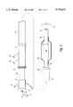
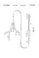
- FIG. 1is a schematic representation of one embodiment of a device for providing thick polymeric gels on the interior of a body lumen.
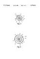
- FIG. 2is a cross-sectional view through line 2--2 of FIG. 1 at a region proximal to a proximal occlusion balloon.
- FIG. 3is a cross-sectional view through line 3--3 of FIG. 1 at a region within a molding balloon.
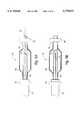
- FIG. 4is a schematic representation of a second embodiment of a device for providing thick polymeric gel on a luminal wall.
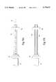
- FIGS. 5A and 5Bare schematic representations of still another embodiment of a device for providing a thick polymeric film on a luminal wall.
- FIG. 6is a schematic representation of an optical emitter catheter.
- FIG. 7is a schematic representation of one embodiment of a device for providing a polymeric barrier layer on a luminal wall.
- FIG. 8is a cross-sectional view through line 8--8 of FIG. 7 at a location proximal to a proximal occlusion balloon.
- FIG. 9is a cross-sectional view through line 9--9 of FIG. 7 across an optical emitter.
- FIG. 10is a schematic representation of a second embodiment of a device for providing a polymeric barrier layer on a luminal wall.
- FIGS. 11A and 11Bare schematic representations of a third embodiment of a device for providing a polymeric barrier layer on a luminal wall.
- FIGS. 12A and 12Bare schematic representations of a device having a valve-occlusion balloon.
- FIGS. 13A and 13Bare schematic representations of a device having a flow-directing baffle.
- FIG. 14is a schematic representation of a device including a flushing sleeve and a valve-occlusion balloon.
- FIG. 15is a cross-sectional view through line 15--15 of FIG. 14.
- FIG. 16is a schematic representation of the device illustrated in FIG. 14, including an arrangement of orifices at the proximal end of the device for accessing various lumens and passageways of the device.
- the devices of the present inventionare adapted to allow a physician to apply a polymeric paving material to the interior of body lumens or spaces, whether natural or induced.
- the devicesmay be configured in a manner that allows the physician to provide either a thick polymeric coating or a thin "interfacial" coating on the tissue surface.
- the devicecan include at least one occlusion element to define at least one end of a treatment space, a molding member to mold and shape the coating material into a desired configuration, and an optical emitter for transmitting light to the coating material in order to initiate polymerization of the material.
- the devicescan include at least one occlusion element to define at least one end of the treatment space, and an optical emitter for transmitting light to the coating material.
- an optical emitterfor transmitting light to the coating material.
- FIG. 1is an illustration of one embodiment of a device for applying thick gels to tissue lumens.
- the device 10comprises three separate elements: a guidewire 12, a balloon catheter 14 and a sheath 16.
- the guidewire 12may be any of a wide variety of guidewires known in the art for intraluminally guiding a catheter to a treatment site such as a coronary artery.
- the balloon catheter 14comprises an elongated tubular shaft 20 having a central lumen, a molding member comprising molding balloon 24 and a distal occlusion element comprising distal occlusion balloon 26, both balloons being mounted near the distal end of the shaft 20.
- An optical emitter 28is mounted within the interior of the molding balloon and serves to supply a substantially uniform field of light for carrying out the photopolymerlzation process in a manner described below.
- One or more radiopaque markers 32comprising, for example, bands of a radiopaque metal such as tantalum, can optionally be positioned at various locations on the device.
- the sheath 16includes two lumens. One is an annular space defined in part by the interior of the sheath, and is sufficiently large to surround the balloon catheter 14 when the molding balloon 24 and the distal occlusion balloon 26 are deflated. A second communicates with a proximal occlusion element which comprises a proximal occlusion balloon 30 mounted at or near the distal end of the sheath.
- the proximal end of the deviceincludes a hub assembly 11, having a central lumen to access the central lumen of the catheter shaft 20, a molding balloon inflation port 13, a distal occlusion balloon inflation port 15, and an optical fiber connector 17 which is attachable to a light source (not shown) to provide light to the optical emitter 28.
- An additional hub 19is provided. Hub 19 is operatively connected to sheath 16 to serve as an actuator to position the sheath and the proximal occlusion balloon 30. Hub 19 also acts as a hemostatic valve. A collar 21 positioned at the proximal end of hub 19 allows the practitioner to position the sheath.
- Hub 19includes a proximal occlusion balloon inflation port 23 and a treatment fluid injection port 25 through which fluids may be injected into the treatment space via an annular space (described below) between the interior of the sheath 16 and the exterior of the catheter shaft 20.
- the shaft 20 of the balloon catheter 14can include three lumens extending from its proximal end.
- a central lumen 34provides a space through which the guidewire 12 may be passed.
- a molding balloon inflation lumen 36communicates with the interior of the molding balloon 24 and molding balloon inflation port 13, thereby allowing the molding balloon to be inflated.
- a distal occlusion balloon lumen 38communicates with the interior of the distal occlusion balloon 26 and distal occlusion balloon inflation port 15, thereby allowing that balloon to be inflated.
- the deviceneed not be limited solely to catheters having a central lumen passing entirely though the catheter shaft.
- the catheterscan include a separate, shorter lumen having one end which exits the catheter at or near the distal end of the catheter shaft and a second opening somewhat proximal to the distal end of the shaft.
- Such so-called “rapid exchange” or “monorail” cathetersare designed to facilitate catheter exchanges while maintaining positioning of a guidewire.
- Monorail cathetersare known in the art, being described, for example, in U.S. Pat. No. 4,762,129 to Bonzel.
- the sheath 16surrounds the balloon catheter 14 and provides an annular space 40 through which fluids may be injected into a treatment space defined between the proximal 30 and distal 26 occlusion balloons.
- the sheath 16includes a proximal occlusion balloon lumen 42 which communicates with the interior of the proximal occlusion balloon 30 and proximal occlusion balloon inflation port 23, and allows that balloon to be inflated.
- an optical emitter 28is positioned within the interior of the molding balloon 24 and serves to direct light provided by at least one, and preferably a plurality of optical fibers 44 circumferentially outward in a substantially uniform manner.
- the optical fiberscommunicate with the emitter 28 either through the molding balloon inflation lumen 36, or, in the alternative, through a separate optical fiber lumen 48 (shown in phantom in FIG. 2) provided in the shaft 20.
- the optical emitter 28comprises a flexible, translucent tube 50 containing a light scattering filler 52.
- the fillercan comprise a translucent matrix containing a light-scattering medium such as titanium dioxide (TiO 2 ) particles.
- a light-scattering mediumsuch as titanium dioxide (TiO 2 ) particles.
- Other light scattering media suitable for use in accordance with the inventioninclude Zr 2 O 3 , Ba 2 SO 4 , diamond dust, glass beads and combinations thereof, with or without TiO 2 .
- the distal ends of the optical fibers 44terminate within the light-scattering filler to allow light exiting from the fibers to be scattered in a substantially uniform radial and circumferential manner.
- the catheter shaft 20may be translucent at least at its distal end.
- a lumen passing through the translucent portionmay be filled with a light-scattering filler as described above, and an optical fiber or fibers can be positioned within the filler.
- the optical fiber or fibersmay be etched, cleaved, tapered or otherwise modified prior to insertion into the filler.
- the resulting catheterhas, as an integral element, a light scattering optical emitter.
- the emittermay be attached to the optical fiber by taper joint, lap joint, or other known joining means.
- a separate light source/controller(not shown) is connected to the proximal ends of the fibers via optical fiber connector 17 and serves to transmit light through the fibers into the emitter.
- concentration and composition of the scattering particles, and the number, positioning, and shape of the distal ends of the fiberscan be controlled.
- Methods for achieving desired distributions of light intensityare known in the art and include simple arrays of scattering particles embedded in plastic as exemplified in U.S. Pat. No. 5,169,395 to Narciso, Jr.; and gradients of scattering particles as exemplified in U.S. Pat. No. 5,196,005 to Doiron et al.
- the flexible, translucent tube 50 of the emitter 28comprises a flexible material which minimizes absorption of light in a wavelength spectrum provided by the light source/controller.
- Numerous translucent polymeric materialsincluding polyethylene terephthalate, polytetrafluoroethylene, polypropylene, silicone, and the like can be used. Polyethylene is preferred.
- the light scattering filler 52preferably comprises a transparent or translucent matrix, for example an epoxy adhesive, containing the light-scattering particles.
- the matrix containing the light-scattering particlesmust be substantially transparent to the wavelength spectrum of light which is to be passed through the emitter.
- the molding balloon and the balloon inflation mediummust be transparent to the light in order to allow the light to pass through the balloon and the medium and into the prepolymer material positioned in the treatment space between the proximal and distal occlusion balloons.
- the emittermay be formed integrally on the distal end of the optical fibers themselves.
- the distal end of the fibersmay be chemically or mechanically modified in a manner which causes the fibers to radiate light laterally in the region of modification.
- the distal end of the fibersmay be ground or chemically modified to "frost" the fiber, thereby to provide light scattering sites directly on the fiber surface.
- Optical fibers modified in this mannercan simplify the manufacture of the devices in that the need to assemble a separate optical emitter within the molding balloon portion of the device is eliminated. Still another emitter embodiment will be described below in connection with FIG. 6.
- the catheter shaft 20, at least in the region of the optical emitter 28,is transparent to light in the wavelength spectrum being used to prevent "shadowing" of the light.
- a reflective coatingmay be formed about the catheter shaft 20 in the region of the optical emitter to reflect any light scattered toward the shaft by the light scattering medium.
- the reflective coatingpreferably comprises a thin coating of silver, and for light in the infrared spectrum, the reflective coating preferably comprises a thin coating of gold.
- Such coatingscan be deposited using any of a variety of known methods for depositing metal on polymeric surfaces, including but not limited to sputtering, ion bombardment, and ion-assisted vapor deposition.
- the catheter shaft 20may be fabricated of any of a wide variety of materials that are sufficiently flexible and biocompatible. For example, polyethylenes, nylons, polyvinylchlorides, polyether block amides, polyurethanes, and other similar materials are all acceptable. It is preferred that the material have a low coefficient of friction, at least within the central lumen 34 to facilitate movement of the device over the guidewire 12. Alternatively, the central lumen 34 may be coated with a material to lower the frictional forces between the luminal walls and the guidewire. For example, if the catheter comprises a urethane, a polyethylene oxide-based material may be coated onto the lumens of the device to provide lubricity.
- the molding balloon 24comprises a non-compliant or is moderately compliant balloon such as those typically used in angioplasty procedures.
- Materialssuch as polyethylene terephthalates or crosslinked polyethylenes exhibit little change in maximum diameter over a wide range of inflation pressures, and accordingly offer desirable properties. Irradiated polyethylenes are also desirable in that they have low surface energy, thereby minimizing the effect of polymeric materials sticking to the molding balloon. Since non-compliant balloons, when inflated, maintain a substantially constant size regardless of their internal pressure, it is preferred that in the case of thick gel applications the balloon be sized approximately 0.20-1.0 mm less than the diameter of the vessel to be treated, thereby providing a gel coating on the interior of the lumen having a thickness of approximately 0.10-0.50 mm.
- a moderately compliant balloonsuch as one made of a urethane, a polyolefin or a nylon may be used.
- a single devicecan be used to cover a wider range of treatment vessel diameters while allowing a tailored gel thickness.
- At least part of the molding balloon, and the medium used to inflate the balloonmust be transparent to the light provided by the optical emitter.
- the balloonmay be entirely transparent, or only the flatter portion parallel to the vessel wall may be transparent, with the conical portions coated to block the exciting light.
- a suitable inflation mediumcomprises a mixture of saline and an iodinated contrast agent. The mixture is both transparent to light provided by the emitter and radiopaque to allow fluoroscopic visualization when the balloon is inflated. It is preferred that the balloon be relatively thin walled so that its deflated condition will offer a low profile to facilitate delivery of the device through the sheath.
- the balloonmust readily release and not stick to the material which is to be photopolymerized.
- Polyethylene and polyolefin balloonshave low energy surfaces and are therefore desirable.
- a coating having low surface energymay be used to facilitate release of the polymeric material from other balloons.
- Such coatingsinclude silicone oils, fluoropolymers, surfactants, hydrogels or other materials having low surface energy.
- the distal occlusion balloonmay be formed of a material similar to that of the molding balloon. However, it is preferred that the distal occlusion balloon be formed of a relatively compliant material to offer the physician greater flexibility in the inflated size of the balloon in order to provide complete occlusion of the body lumen at the site at which the distal occlusion balloon is positioned. Furthermore, compliant occlusion balloons are likely to be less traumatic to the tissue lumen, thereby reducing the potential for complications as a result of over-inflation. Suitable compliant balloon materials include, but are not limited to latex, urethanes, polyether block amides, and the like. The distal occlusion balloon need not be transparent to light provided by the optical emitter.
- the occlusion sheath 16comprises an elongate flexible tube having a wall thickness on the order of about 0.003-0.004 inches, and an internal diameter large enough to contain the balloon catheter 14 when both the molding balloon 24 and the distal occlusion balloon 26 are in their deflated states.
- the interior diameter of sheath 16must be substantially larger than the outer diameter of the balloon catheter shaft 20 in the region proximal to that region of shaft 20 extending distally from sheath 16 when shaft 20 is in its operative position. In this way, an annular space 40 is defined between the sheath and the shaft 20 through which the photopolymerizable prepolymer and other fluids may be injected into the treatment site, and through which other devices may be inserted if desired.
- the sheathis axially moveable relative to the shaft in order to allow the shaft and its balloons to be withdrawn through the sheath to provide interchangability of such devices. Furthermore, by allowing relative axial movement between the proximal and distal occlusion balloons, the axial length of the treatment space may be varied, thereby allowing the physician to tailor the device to the particular lesion being treated.
- the interior wall of the sheath lumenhave a low coefficient of friction to facilitate movement of the sheath over the balloon catheter.
- materials that may be used to form the sheathare fluoropolymers, high density polyethylenes, polyether block amides, thermoplastic elastomers, or urethanes.
- coatingssuch as surfactants, hydrogels, silicone oils or fluoropolymers may be provided.
- the sheathfurther includes a proximal occlusion balloon lumen 42 which communicates with the interior of the proximal occlusion balloon 30 to allow that balloon to be inflated.
- the proximal occlusion balloon 30is of substantially the same construction as that of the distal occlusion balloon 26 described above.
- each of the device componentsshould be sized appropriately to facilitate delivery and to minimize profile.
- the devicecan be inserted within a targeted lumen causing minimal trauma at the treatment site.
- the profile of the occlusion sheathis preferably no larger than about 1.6 mm (about 0.065 inches) to allow delivery through a standard coronary guiding catheter.
- the balloon cathetermust be sized to move effectively within the sheath and to allow delivery of polymeric material in the space between the sheath inner diameter and the balloon catheter outer diameter.
- the devicemust also be sized to easily pass through obstructed lesions and to be deliverable over small diameter guidewires, such as guidewires having a diameter of approximately 0.30-0.45 mm (about 0.012-0.018 inches) commonly used in the coronary arteries.
- the deviceis positioned at a treatment site, typically post-angioplasty, using standard percutaneous transluminal catheterization procedures.
- a treatment sitetypically post-angioplasty
- each of the proximal occlusion balloon, distal occlusion balloon, and molding balloonare deflated and the distal end of the sheath is advanced to a location proximal to the distal end of the balloon catheter.
- the guidewire used to position the dilatation catheteris left in place. If the procedure is carried out at a time other than post-angioplasty, the guidewire is inserted into a patient and navigated until its distal end crosses a treatment location.
- the deviceis passed over the guidewire until the molding balloon has been positioned at the desired treatment location. Since the distal occlusion balloon is, in this case, mounted on the same shaft as the molding balloon, positioning of the molding balloon serves to position the distal occlusion balloon as well.
- the proximal occlusion balloonis then positioned proximal to the molding balloon to define the proximal end of the area to be treated. Once inflated in the manner described below, the region between the proximal occlusion balloon and the distal occlusion balloon defines a space that is referred to herein as the "treatment space".
- the occlusion balloonsare inflated to define the treatment space and to occlude the body lumen at both the proximal and distal ends of the treatment space. It is preferred that the proximal occlusion balloon be inflated prior to the distal occlusion balloon to allow blood and other biological fluids contained within the body lumen to be removed prior to sealing the treatment space between both occlusion balloons.
- the treatment spacemay be filled or flushed with a solution, such as an inert saline solution, to remove blood and other biological fluids from the treatment space prior to inflation of the distal occlusion balloon.
- a solutionsuch as an inert saline solution
- the solutionsmay be introduced through a port such as a side arm on a Touhey-Borst adapter or a similar device positioned at or near the proximal end of the catheter shaft.
- a non-inert solutionsuch as a solution containing a pharmaceutical agent may be injected into the treatment space.
- solutions of tPA, streptokinase, urokinase, and the likeare preferred, although virtually any pharmaceutical or therapeutic agent capable of being applied using the devices disclosed herein and offering a desired pharmaceutical or therapeutic effect may be used, either alone or in various combinations. Additionally, it is contemplated that one or more therapeutic agents for treatment of tissue or for preventing the deposition of substances from body fluid contained in the vessel may be incorporated into a prepolymer solution.
- pharmaceutical or therapeutic agentrefers to substances which alter the metabolism of cells or which reduce the tendency for thrombosis or morbidity within diseased portions of the tissue.
- vasodilating agentsi.e., nitrates and calcium channel blocking drugs
- anti-proliferative agentsi.e., colchicine and alkylating agents
- intercalating agentsgrowth modulating factors such as interleukins, transformation growth factor b, congeners of platelet derived growth factor and monoclonal antibodies directed against growth factors
- anti-thrombotic agentse.g., anti-GIIb/IIIa, trigramin, prostacyclin, salicylates, and tissue-factor pathway inhibitors
- thrombolytic agentse.g., streptokinase, urokinase, tissue plasminogen activator (tPA) and anisoylated plasminogen-streptokinase activator complex (APSAC); anti-inflammatory agents
- Anti-proliferative drugs or high efficacy anti-inflammatory drugsare also useful for treatment of focal vasculitides or other inflammatory arteritidies, e.g., granulomatous arteritis, polyarteritis nodosa, temporal arteritis and Wegner's granulomatosis. Anti-inflammatory agents are also useful in connection with indications such as inflammatory bowel disease, Crohn's disease, ulcerative colitis and focal GI inflammatory diseases.
- adhesivesmay be introduced in accordance with the invention to help heal dissections, flaps and aneurysms. Exemplary adhesives include cyanoacrylates, gelatin/resorcinal/formol, mussel adhesive protein and autologous fibrinogen adhesive.
- the term "therapeutic agents"does not encompass solubilizing or dissolving agents which disrupt the atherosclerotic plaque.
- the flushing liquidsmay be injected into the treatment space through the annular space 40 between the sheath 16 and the balloon catheter shaft 20. Once the treatment space has been cleared of blood and other biological fluids, the distal occlusion balloon is inflated to thereby seal and define the treatment space.
- the devicemay be provided with an additional flushing, or drain lumen whereby the flushing liquids injected into the treatment space exit through the additional lumen and out of the patient through the proximal end of that lumen.
- all liquidsi.e., flushing, prepolymer, photoinitiator
- the devicemay be provided with an additional flushing, or drain lumen whereby the flushing liquids injected into the treatment space exit through the additional lumen and out of the patient through the proximal end of that lumen.
- the devicemay also be provided with a perfusion lumen that allows blood to bypass the treatment space during the treatment process.
- a lumenincludes one or more ports which communicate with the exterior of the catheter at a location proximal to the proximal occlusion element and distal to the distal occlusion element.
- bloodcan enter the perfusion lumen through the proximal perfusion port, travel within the perfusion lumen through the treatment space, and return to the blood vessel through the distal perfusion port.
- some blood flow across the treatment spaceis provided, thereby providing blood to the lumen distal to the treatment space.
- a prepolymer fluid to be photopolymerizedis injected into the treatment space through the annular space 40.
- an additional flushing lumen or a valve-occlusion balloon(described below) is not provided, it is preferred that the distal occlusion balloon be deflated simultaneously with injecting the prepolymer fluid into the treatment space. In this manner, the flushing fluid that occupies the treatment space prior to prepolymer injection will be displaced distally by the prepolymer. Once the prepolymer has replaced the flushing fluid in the treatment space, the distal occlusion balloon is inflated to contain the prepolymer.
- the flushing fluidcan be displaced by the prepolymer and removed through that lumen.
- the prepolymeris described in detail in the aforementioned Hubbell applications, it is noted that it preferably contains a photoinitiator to cause crosslinking in the prepolymer upon exposure to light.
- the molding balloonis inflated to thereby form the prepolymer fluid into an annular "sleeve" in contact with the interior surface of the body lumen.
- the molding balloonis preferably expanded to a size which provides a clearance of between approximately 0.10 and 0.50 mm between the balloon surface and the interior surface of the body lumen. It is noted, however, that much greater clearance may be provided if thicker gels are desired.
- the present inventioncould be used to provide gels having a thickness of 10 mm or greater if desired for a particular application.
- one primary function of the molding balloonis to provide a means for maintaining a patent lumen of predefined diameter following gel formation within the body lumen.
- the molding balloonUpon expansion of the molding balloon, light energy is supplied through the optical fibers to the optical emitter. The light diffuses outwardly from the emitter, and through the balloon inflation medium and the balloon. Upon transmission through the balloon, the light energy is absorbed by the photoinitiator contained in the prepolymer fluid thereby causing the prepolymer to become crosslinked.
- the light sourceis turned off and the molding balloon is deflated, thereby leaving a polymeric sleeve having a thickness of approximately 0.10-0.50 mm on the interior surface of the body lumen.
- the proximal and distal occlusion balloonsare then deflated and the device is withdrawn from the body lumen, leaving the sleeve in place.
- the specific sequence of the balloon inflation and light irradiation stepsis intended merely as an example, and that many variations to the sequence are contemplated as well.
- the molding balloonmay be inflated simultaneously with introduction of light to the prepolymer material, or the photopolymerization process may be initiated prior to inflation of the molding balloon.
- the devicecan be constructed to have only a single, proximal or distal occlusion balloon.
- the single occlusion balloonis inflated, the flushing liquid is injected, followed immediately by the injection of the prepolymer liquid.
- photopolymerizationis carried out as described above.
- the treatment spacecan be defined, in more general terms, as an area at which the polymer, light and tissue physically intersect at a given time.
- occlusion balloonsit is possible to eliminate the occlusion balloons altogether.
- the polymeric materialis to be applied to the surfaces of a natural or induced body lumen or space through which a body fluid is not continuously flowing, occlusion of the region to be treated can be eliminated if the body fluid can be adequately displaced by the injection of flushing solutions and/or the prepolymer liquid.
- the elements of the device described aboveneed not be separate. Rather, a single shaft incorporating any or all of the occlusion balloons, molding balloon, and optical emitter can be used to apply polymeric material to tissue surfaces using the methods described above.
- FIG. 4Another embodiment of the device is depicted schematically in FIG. 4.
- the device of FIG. 4differs in that the distal occlusion balloon is positioned on the guidewire, rather than on the balloon catheter shaft in the region distal to the molding balloon.
- the devicecomprises a guidewire 60 having a distal occlusion balloon 62 positioned at its distal end.
- Such so-called "balloon-on-a-wire" devicesare known in the art, being described, for example in U.S. Pat. No. 4,582,181 to Samson and in U.S. Pat. No. 4,846,174 to Willard et al.
- the balloon catheter 64is identical to that described previously with the exception that it does not include the distal occlusion balloon 62 or a lumen communicating with that balloon.
- the molding balloon 24, the optical emitter 28, the sheath 16, the proximal occlusion balloon 30, and the marker 32are identical to those described previously.
- the proximal end of the deviceis similar to that of FIG. 1 with the exception that the distal occlusion balloon inflation port 61 has been positioned on the guidewire 60 consistent with the "balloon-on-a-wire" design.
- the optical emitteris not included as part of the balloon catheter assembly, but rather, comprises a separate element that is inserted through the central lumen of the balloon catheter during the treatment procedure. More particularly, such a device 80 comprises three separate elements: a guidewire 12, a balloon catheter 82 and a sheath 16.
- the guidewire 12may be any of a variety of guidewires known in the art for intraluminally guiding a catheter to a treatment site.
- the balloon catheter 82comprises an elongated tubular shaft 84 having a molding balloon 86 and a distal occlusion balloon 88, both mounted near the distal end of the shaft 84.
- One or more radiopaque markers 32may be positioned on the balloon catheter shaft 84.
- the sheath 16includes a lumen having a diameter sufficiently large to receive and enable passage of the balloon catheter 82 when the molding balloon 86 and the distal occlusion balloon 88 are deflated.
- a proximal occlusion balloon 30is mounted at or near the distal end of the sheath.
- the shaft 84 of the balloon catheter 82includes at least three lumens: a first lumen communicating with the interior of the distal occlusion balloon 88, a second lumen communicating with the interior of the molding balloon 86 and a third lumen passing entirely through the shaft through which the guidewire. 12 may be passed.
- the proximal end of the deviceis similar to that of FIG. 1 with the exception of the optical fiber connector 17 which is absent in the embodiment of FIG. 5A.
- the device 80further includes a separate optical emitter 90 that may be inserted through the balloon catheter shaft 84 after the guidewire 12 is removed.
- the optical emitter 90has, at its distal end, a flexible, translucent tube 92 containing a light scattering filler 94, such as that described previously.
- the filler 94is contained at the distal end of an elongated emitter shaft 96 having a central lumen therethrough.
- At least one optical fiber 98passes through the lumen of the emitter shaft 26 and has its distal end terminating within the light scattering filler 94.
- the proximal end of the optical fiber 98is connected to the light source/controller (not shown) via an optical fiber connector 91 which accesses the emitter shaft 96 through a proximal hub 93.
- One or more radiopaque markersmay be provided on the emitter to assist in determining the position of the emitter once it is inserted into the patient.
- the emitter tube 92must be formed of a material that is substantially translucent or transparent to the light delivered through the optical fiber. Numerous translucent polymeric materials can be used, however, polyethylene is preferred.
- the emitter tube and emitter shaftmay be a single integral shaft formed of a translucent or transparent material and loaded with the light scattering filler only at its distal end.
- a single optical fiber having a emitter positioned at its distal endmay be used.
- the emittercomprises a transparent or translucent tube filled with a transparent or translucent binder material and a light scattering medium.
- the distal end of the optical fiberis inserted a short distance into the proximal end of the emitter, thereby providing a source of light to the emitter.
- the fibercan be inserted into an emitter formed of a translucent polymer having either inherent scattering characteristics or scattering media compounded therein.
- at least one optical fiber having its distal end chemically or mechanically modified to radiate light laterallycan be substituted for or combined with the emitters described above.
- the devicein use, is positioned at a treatment site, typically post-angioplasty, using percutaneous transluminal catheterization procedures.
- a treatment sitetypically post-angioplasty
- the balloons of the devicePrior to insertion into a patient, the balloons of the device are deflated and the distal end of the sheath is advanced over the balloon catheter to a location proximal to the distal end of the catheter.
- the deviceis passed over the previously placed angioplasty guidewire until the molding balloon is positioned at the treatment location.
- the proximal occlusion balloonis then positioned at a desired proximal position.
- the occlusion balloonsare inflated and the guidewire is withdrawn.
- the balloonsmay be inflated either simultaneously or sequentially, the order being determined, in part, by the need to displace fluid in the treatment space prior to introduction of the prepolymer material.
- a flushing step, as described above,may optionally be performed.
- the optical emitter 90is inserted through the central lumen of the balloon catheter shaft 84 and advanced to position the emitter tube 92 in the portion of the shaft 84 surrounded by the molding balloon 86.
- a prepolymer material containing a dye or other photoinitiatoris injected into the treatment space between the proximal 30 and distal 88 occlusion balloons and then molded and photopolymerized by expansion of the molding balloon 86 and illuminated with light from the optical emitter 90 in the manner described previously.
- the balloon catheter shaft 84at least in the region of the optical emitter tube 92, must be substantially transparent or translucent to light radiating from the emitter in order to allow that light to pass into and through the molding balloon.
- the light sourceis turned off and the molding balloon, the proximal occlusion balloon and the distal occlusion balloon are each deflated and the device is withdrawn from the body lumen, leaving a photopolymerized sleeve of polymeric material in place within the body lumen.
- Each of the aforementioned embodimentsis directed to a device for providing a relatively thick (i.e., about 0.10-0.50 mm) polymeric coating on the interior of a body vessel.
- the devicemay be used to conduct: an interfacial polymerization procedure to form a relatively thin (i.e., about 0.005-0.10 mm) barrier coating on the interior surface of a body lumen.
- the interfacial polymerization procedureinvolves, as a preliminary step, contacting the surface to be treated with a photoinitiator for a time sufficient to allow the tissue surface to adsorb a portion of the photoinitiator, and then contacting that surface with a polymer solution while simultaneously or subsequently irradiating the interface with light.
- the lightinteracts with the photoinitiator at the tissue surface causing a polymer film to crosslink and "grow" from the tissue surface into the lumen.
- the unpolymerized solutionis removed from the treatment space leaving behind a thin barrier layer of crosslinked polymer on the luminal surface.
- prepolymer solutionscan include macromers made up of a biodegradable region, preferrably hydrolyzable under in vivo conditions, a water soluble region, and at least two polymerizable regions.
- the polymerizable regionshave the capacity to form covalent bonds resulting in macromer interlinking, for example, carbon-carbon double bonds of acrylate-type molecules.
- Such polymerizationis characteristically initiated by free-radical formation resulting, for example, from photon absorbtion of certain dyes and chemical compounds to ultimately produce free radicals.
- the polymerizable speciesgenerally contains ethylenically unsaturated groups, for example acrylates, diacrylates, oligoacrylates, methacrylates, dimethacrylates, oligomethacrylates, or other biologically acceptable photopolymerizable groups.
- Useful photoinitiatorsare those which can be used to initiate by free radical generation polymerization of the macromers without cytotoxicity and within a short time frame.
- Prefererd dyes as initiators for UV or visible light initiationare ethyl eosin, 2, 2-dimethoxy-2-phenyl acetophenone, other acetophone derivatives, and camphorquinone. These and other polymerizable species and photoinitiators are described in the above-reference Hubbell U.S. patent applications and international publications.
- the interfacial polymerization processcan be carried out using a device such as that depicted schematically in FIG. 7.
- the device of FIG. 7is substantially identical to that of FIG. 1 except that it does not include a molding balloon or molding balloon inflation lumen.
- the device 100comprises three elements: a guidewire 12, a polymerization catheter 102 and a sheath 16.
- the guidewireis as described previously.
- the polymerization catheter 102comprises an elongated tubular shaft 104 having a distal occlusion balloon 106 mounted near its distal end.
- An optical emitter 108constructed in a manner substantially identical to that of the emitter in FIG. 1, is mounted on the polymerization catheter 102 in a region proximal to the distal occlusion balloon 106.
- One or more radiopaque markers 32can optionally be positioned at various locations on the shaft 104.
- the sheath 16includes a lumen having a diameter sufficiently large to enable passage of the polymerization catheter when the distal occlusion balloon 106 is deflated.
- a proximal occlusion balloon 30is mounted at or near the distal end of the sheath.
- sheath 16includes a proximal occlusion balloon lumen 42 which communicates with the interior of the proximal occlusion balloon 30 and allows it to be inflated.
- Shaft 104 of the polymerization catheter 102includes multiple lumens extending from its proximal end.
- a central lumen 110provides a space through which the guidewire 12 may be passed.
- a distal occlusion balloon lumen 112communicates with the interior of the distal occlusion balloon 106, thereby allowing that balloon to be inflated.
- the sheath 16surrounds the polymerization catheter 102 and provides an annular space 40 through which a prepolymer fluid may be injected into a treatment space positioned between the proximal 30 and distal 106 occlusion balloons.
- the catheter shaft 104can further include at least one optical fiber lumen 114 through which at least one optical fiber 44 may pass, or in the alternative, the fiber may pass through the annular space 40 between the sheath and the polymerization catheter, or within the distal inflation lumen 112.
- the optical fiber and emittermay be placed within any lumen.
- the various lumensin this and in other embodiments, may be arranged in any suitable pattern; for example, so as to maximize the size of the various lumens within a given catheter shaft size.
- an optical emitter 108 positioned on the polymerization catheter shaft 104comprises a flexible, translucent tube 116 containing a light scattering filler 52 of the type described earlier.
- One or more optical fibers 44have distal ends terminating in the light scattering filler 52.
- a reflective coatingmay be formed on the shaft 104 contained within the emitter 108. The material of construction for each of the occlusion balloons, the sheath, the polymerization catheter, and the optical emitter are as described above.
- the proximal and distal occlusion balloonsare deflated and the sheath is extended over the polymerization catheter to a point proximal to the distal end of the polymerization catheter.
- the polymerization catheter with the distal occlusion balloonis guided over the guidewire to position the distal occlusion balloon at the distal end of the treatment site.
- the sheathis then positioned to place the proximal occlusion balloon at a desired proximal location.
- the proximal occlusion balloonis inflated to occlude the proximal end of the treatment site, and a flushing solution, as described previously, is injected through the annular space between the sheath and the polymerization catheter to flush blood and other biological fluids from the treatment site.
- a photoinitiatoris injected through the annular space to coat and/or adsorb into tissue at the interior surface of the body lumen.
- the unbound photoinitiatormay be removed by flush.
- a prepolymer solutionis injected into the treatment space between the proximal and distal occlusion balloons, which may displace the photoinitiator, and the distal occlusion balloon is inflated.
- the distal occlusion ballooncan be inflated earlier. In that case, fluid in the treatment space displaced by subsequent fluids would be displaced and removed through the "flushing" lumen.
- barrier layer"grows" outwardly into the lumen with continued illumination time. Unpolymerized material may then be flushed or aspirated from the treatment site. The balloons are then deflated and the device is withdrawn, leaving a thin barrier layer of polymeric material on the surface of the luminal wall.
- barrier layeris meant to define, generally, a polymer layer that isolates a region of tissue. However, this term is meant to include also polymeric material which contacts tissue to provide structural support, to deliver pharmaceutical agents, and the like, where a continuous barrier is not necessarily formed.
- each of the proximal and distal occlusion balloons, and the emitterin their various combinations, may be mounted on a single multi-lumen shaft.
- at least one additional lumenis provided for introduction of a photoinitiator, a flushing solution, and/or prepolymer. If the single shaft embodiment is used, the ability to tailor the size of the treatment space is lost.
- the simplicity of the single shaft deviceovercomes the inability to vary the treatment space length for many applications.
- the devicemay be used to withdraw flushing liquid in the manner described previously.
- the numerous variations on the device described with respect to FIGS. 1-6can be incorporated into the devices for application of thin interfacial gels as well.
- the device of FIG. 10differs in that the distal occlusion balloon is positioned on the guidewire rather than on the balloon catheter shaft in the region distal to the molding balloon.
- the devicecomprises a guidewire 60 having a distal occlusion balloon 62 mounted at its distal end.
- the polymerization catheter 118is identical to that described previously with the exception that it does not include the distal occlusion balloon 62 or its related lumen.
- the emitter 108, the sheath 16, the proximal occlusion balloon 30 and the marker 32are identical to those described earlier.
- the proximal end of the device of FIG. 10is similar to that of FIG. 4 with the exception that hub 11 does not include a molding balloon inflation port.
- the method of operation of the device of FIG. 10is substantially the same as that for the device depicted in FIG. 7.
- the proximal 30 and distal 62 occlusion balloonsare deflated and the guidewire is navigated across a treatment site to position the distal occlusion balloon at the distal end of the treatment site.
- the polymerization catheter 118is then advanced to position the emitter 108 at the treatment site.
- the sheath 16is positioned to place the proximal occlusion balloon 30 at the proximal end of the treatment site.
- the proximal and distal occlusion balloonsare then inflated, either simultaneously or sequentially in the same manner as described previously.
- the treatment siteis then optionally flushed, coated with a photoinitiator, contacted with a prepolymer solution, and subjected to interfacial polymerization in the manner described above.
- the balloonsare deflated and the device is withdrawn, leaving the polymeric barrier in place.
- FIGS. 11A and 11Bdiffers from the device of FIG. 7 in that a separate optical emitter 90 is used to provide light for the interfacial polymerization.
- the device of FIG. 11Aincludes a guidewire 12, a treatment catheter 120 having a distal occlusion balloon 106 at its distal end and a sheath 16 having a proximal occlusion balloon 30 positioned at or near its distal end.
- the treatment catheter 120is transparent or translucent to the photopolymerizing light at least in the region that becomes exposed between the proximal and distal occlusion balloons.
- the proximal end of the deviceis similar to that of FIG. 7 with the exception of the optical fiber connector which is absent in the embodiment of FIG. 11A.
- the angioplasty guidewireis left in position across a treatment location.
- the proximal and distal occlusion balloonsare deflated and the treatment catheter 120 is advanced distally to position the distal occlusion balloon at a location near the distal end of the treatment site.
- the sheathis then positioned over the guidewire to place the proximal occlusion balloon proximally adjacent to the treatment site.
- the proximal occlusion balloonis inflated and the treatment space is optionally flushed and coated with a photoinitiator in the manner described previously.
- the guidewireis withdrawn, and the optical emitter is then guided through the central lumen to position emitter tube 92 within the treatment space.
- a prepolymer solutionis injected into the space between the proximal and distal occlusion balloons and the distal occlusion balloon is inflated.
- the prepolymerthen is irradiated with light from the optical emitter in the manner described previously.
- the resulting polymerized layercomprises a thin barrier layer of polymeric material on the luminal surface.
- the balloonsare deflated and the device is withdrawn, thereby leaving the polymeric barrier in position on the luminal wall.
- the treatment spaceis defined as that region between proximal and distal occlusion balloons which are inflated to isolate a segment of the vessel.
- the proximal and distal occlusion balloonscan each be of generally the same shape and material.
- one of the balloons, preferably the distal occlusion balloonmay be underinflated, fabricated of a particular material, or formed in a particular shape and/or size such that it is provided with a lesser ability to effectively occlude the lumen.
- Such a configurationoffers certain advantages in that the resulting balloon can occlude the vessel while also allowing fluids injected into the treatment space to flow distally beyond the device.
- valve-occlusion balloonsBalloons which offer the ability to occlude the lumen and allow some fluid to exit the treatment space during a fluid injection are referred to herein as "valve-occlusion" balloons.
- a valve-occlusion ballooncan act, in part, as a one-way valve by allowing excess fluid delivered between the balloons to exit from the treatment space in a region that opens between the periphery of the balloon and the lumen wall during enhanced pressure conditions that occur when fluids are injected into the treatment space.
- fluidis allowed to flow beyond the treatment space, thereby alleviating the need for aspirating fluid proximally and limiting hydrostatic intramural chamber pressure without any retrograde flow or seepage of blood to the isolated segment.
- FIGS. 12A and 12BA catheter device including a valve-occlusion balloon is illustrated in FIGS. 12A and 12B.
- the distal end of catheter device 200is positioned within a blood vessel 201.
- the devicecomprises a catheter shaft 202 having proximal 204 and distal 206 occlusion balloons longitudinally spaced apart near the distal end of the catheter shaft 202.
- the sheathhas been eliminated and the proximal occlusion balloon 204 is mounted directly on the catheter shaft 202.
- Fluids 210are injected into the treatment space through one or more ports 208 positioned on the catheter shaft between the occlusion balloons.
- the portscommunicate with at least one lumen in the catheter shaft through which the fluids 210 can be injected.
- a portprovides fluid communication between a lumen within a shaft and a region outside of the shaft
- the port or portsmay be formed by shaving, or skiving, an exterior wall of the shaft to open the lumen.
- a fluid 210 injected into the treatment space(and/or fluid in the treatment space displaced by fluid 210) is allowed to flow past the distal, valve-occlusion balloon 206 about the periphery 212 of that balloon when fluid pressure within the treatment space is sufficient.
- the proximal balloon 204occludes the proximal end of the treatment space and prevents fluid flow in the proximal direction.
- the distal occlusion balloon 206upon termination of injection of the fluid 210 into the treatment space, the distal occlusion balloon 206 reseals the distal end of the treatment space and contains the fluid injected therein.
- Valve-occlusion balloon 206can be formed in various ways. For example, it can be formed using a material that is more compliant than that from which occlusion balloon 204 is formed. Alternatively, both balloons may be manufactured of the same material, however valve-occlusion balloon 206 may be formed with a wall thickness that is less than that of occlusion balloon 204 to thereby render it more flexible. If the balloons are independently inflatable, valve-occlusion balloon 206 may be created by inflation to a lower pressure than that used to inflate occlusion balloon 204. A check valve or the like may be used to achieve underinflation of one balloon relative to the other.
- valve-occlusion balloon 206can have a shape that allows an increase in pressure in the treatment space between the balloons to facilitate removal of fluid from the treatment space past the valve-occlusion balloon.
- valve-occlusion balloon 206may be of a different shape and/or size relative to occlusion balloon 204 so that the area of contact between valve-occlusion balloon 206 and the interior wall of vessel 201 is smaller than the area of contact between balloon 204 and the interior wall of the vessel 201.
- valve-occlusion balloonallows a catheter shaft of the same outer diameter to have a larger central, injection or guidewire lumen, or smaller catheter shaft, than would otherwise be possible.
- the central lumencan be used for blood flow, thereby allowing a higher rate of flow through the catheter than would be possible if a separate drain lumen were required.
- baffle 252comprises an elastic sheath 254 which surrounds the catheter shaft 202 in the region of an injection port 208 and is secured to the catheter shaft by an adhesive 256 at a location distal to the injection port 208.
- fluid 210 exiting the injection portexpands the elastic sheath 254 and is caused to flow proximally in the treatment space toward the proximal occlusion balloon 204.
- the proximal fluid flowremoves residual material positioned at the proximal end 203 of the treatment space adjacent to the proximal occlusion balloon.
- the fluidUpon reaching the proximal end of the treatment space, the fluid begins a distal flow through the entire treatment space and ultimately flows beyond a distally-positioned valve-occlusion balloon 206. Fluid exiting from the injection port 208 is prevented from flowing immediately in the distal direction by the adhesive 256 which is used to secure the elastic sheath 254 to the shaft, effectively creating a barrier.
- the elastic sheath 254retracts about the injection port 208 and catheter shaft 202 into the configuration shown in FIG. 13A to prevent fluid in the treatment space from retrograde flow into the catheter shaft via the injection port.
- the elastic sheathwhile acting as a baffle to direct injected fluid toward the proximal occlusion balloon, the elastic sheath also acts as a one-way check valve to prevent unwanted fluid flow back into the injection port.
- the rate of fluid flow out of injection port 208 and into the treatment space between the occlusion balloonsmay be increased by blocking a lumen in shaft 202, through which the fluid passes, just distal to the port.
- quick-setting adhesive or siliconemay be injected into the lumen just distal to the port so that all fluid flow is directed into the treatment space.
- the present inventionalso provides a device for flushing a surface of a body lumen or cavity with a fluid.
- a distal end of a catheter including such a deviceis illustrated that includes a shaft having a distal end insertable into the lumen or cavity, a proximal end that remains outside of the lumen or cavity, and a perforated flushing sleeve 260 surrounding a portion of the distal end of the shaft.
- the perforated flushing sleeveincludes an interior that is connected to a source of fluid to be ejected into the lumen or cavity, and is positioned at a portion of the shaft that can be placed adjacent portions of the lumen or cavity that desirably are treated with the fluid.
- the flushing sleevecan surround a portion of the shaft that includes one or more fluid ejection ports so as to facilitate delivery of the fluid from the ejection ports into the lumen or cavity via the perforations.
- the flushing sleeveis used in conjunction with a catheter device described hereinabove and illustrated in FIGS. 13A and 13B, for injection of a photoinitiator, prepolymer fluid, flushing fluid, etc. into an occluded region of a body lumen or cavity such as a blood vessel. It is to be understood, however, that the flushing sleeve can be used on any such device where it is desirable to introduce into a body lumen or cavity any fluid such as a therapeutic agent or the like.
- Flushing sleeve 260can be made of any material suitable for use in an environment in which it will be used, such as stainless steel, rigid polymeric material, elastomer, or the like. When made of a relatively rigid material, it can be made to have an inner diameter slightly larger than the exterior diameter of the shaft to provide for fluid flow between the shaft and the sleeve. When made of a flexible material such as an elastomer, the sleeve can have an interior, unstretched diameter less than the exterior of the shaft, or the interior diameter can be equal to or slightly larger than the exterior diameter of the shaft. According to preferred embodiments, the flushing sleeve is made of elastic tubing which is slightly larger in inner diameter than the outer diameter of the shaft 202 of the catheter. Sleeve 260 can be optically clear, or can include light scattering or absorbing characteristics that may be desirable in a particular application, including uneven distribution of light scattering and absorbing characteristics for "shadowing" of electromagnetic radiation directed through the sleeve.
- Flushing sleeve 260includes perforations, or distribution ports 262 through which fluid is delivered to the lumen or cavity.
- Distribution ports 262can be provided in any number, and in a variety of sizes and shapes, and can be distributed evenly or unevenly on the sheath. Preferably, distribution ports 262 are distributed evenly around the entire circumference and length of the flushing sleeve, and number for example from 50 to 100.
- a convenient way of making such distribution ports in an elastomeric sleeve 260is as slits, by the use of a beveled hypodermic needle, which produces slits about 0.25 mm. long. Axial orientation of the slits, as illustrated, is preferred. Other sizes, shapes, and orientations of distribution ports can be provided.
- flushing sleeve 260is advanced over a section of the catheter distal to proximal occlusion balloon 204 and proximal to distal occlusion balloon 206, thereby covering one or more ports (not illustrated) from a lumen of the catheter leading into the occlusion zone.
- Flushing sleeve 260can be immobilized on shaft 202 in one of several ways.
- sleeve 260can be attached to shaft 202 via heat sealing or use of adhesive at one or both ends thereof, and/or at one or more locations along the length of the sleeve.
- either or both of the ends of the sleevecan be completely sealed circumferentially around the shaft, or one or both can be left unsealed to the shaft to allow fluid to emanate from between the exterior of the shaft and the interior of the sleeve.
- one end (or both ends) of the sleevecan be joined to the catheter shaft while at least one passage 266 (FIG. 15, not shown in FIG. 14) is maintained between the sleeve and the shaft at the end that is joined.
- the passage(s) 266is kept patent by suitable means.
- a further improvement in fluid distributioncan be achieved by combining the functions of a flushing sleeve and a flow baffle.
- the combination of these elementsboth flushes potential static regions, and provides mixing throughout the treatment zone between the occluding balloons.
- the distal end 264 of flushing sleeve 260is completely sealed to shaft 202 via adhesive, and the proximal end 265 of the sleeve is sealed to the shaft via adhesive while one or more fluid passages 266 are maintained between the shaft and the sleeve at proximal end 265. Fluid passages 266 are shown in more detail in FIG. 15.
- One convenient mechanism for providing fluid passages 266is the insertion of small fluoropolymer-coated plugs, for example about 0.010 inch (0.25 mm) in diameter, between shaft 202 and sleeve 260 which locally prevent adherence of the sheath and the shaft, and which are removed after the bond is set leaving suitable flushing ports.
- Other options in construction of a flushing sheathinclude having flushing ports at both ends, or having a flushing port at least at one end which operates as shown in FIGS. 13A and 13B.
- the fluid to be injected into the treatment space between occlusion balloons 204 and 206is applied under pressure to the interior of the flushing sleeve through one or more injection ports (not illustrated) on the shaft under the flushing sleeve 260, into the fluid delivery lumen.
- the pressureslightly expands sleeve 260, and thereby opens the perforations, or distribution ports, 262 of the sleeve, providing direct flow of the fluid in a radial direction away from the shaft and sleeve.
- Fluid under pressurealso emerges from the fluid passages 266 (or from between the sleeve and the shaft if an end of the sleeve is not adhered to the shaft), providing the desired axial flushing action in the vicinity of the proximal balloon (and/or the distal balloon).
- the ratios of the clearance of the injection port(s) in the shaft, the size and number of the distribution ports 262, and the diameter of the fluid passages 266desirably are appropriately sized for a particular range of operating pressure and a particular sleeve compliance. The required adjustments are readily achieved by inspecting the flow patterns of dyed liquids ejected through prototype devices in clear tubes similar in size to the particular body lumen or cavity desirably treated.
- FIG. 16A schematic view of a catheter including a flushing sleeve according to one embodiment of the invention is shown in FIG. 16.
- the flushing sleeve 260is shown between the proximal 204 and distal 206 occlusion balloons, all mounted on the catheter shaft 202 which carries radio-opaque markers 32.
- an arrangement of orifices according to one embodimentis illustrated: a proximal balloon control port 280, a connection to an optical fiber 282, a solution injection and flushing port 284, a distal balloon control port 286, a port 288 for a guidewire lumen, and a connector 290 for flushing the guidewire lumen.
- the present inventionalso provides methods of directionally-controlled application of fluid to the interior surface of a body lumen or cavity, which methods can be carried out with the aid of, for example, the flow-directing baffle 254 described above with reference to FIGS. 13A and 13B, the flushing sleeve 260 described with reference to FIGS. 14-16, and/or a preferred embodiment of the flushing sleeve that incorporates axially-directed fluid flow (provided via the principle of the baffle 254 or fluid passages 266).
- the fluid that is applied according to the methodscan be a flushing liquid that optionally contains a pharmaceutical or therapeutic agent, a photoinitiator, a prepolymer fluid, saline solution, or other fluids described herein or that are within the purview of those of ordinary skill in the art.
- a methodis provided that involves providing a fluid to such an interior surface by occluding the lumen or cavity with an occlusion element, and directing pressurized fluid toward the occlusion element so as to flush a region defined by the occlusion element and the surface of the lumen or cavity.
- a methodinvolves, in a lumen or elongated cavity having an axis of elongation, directing fluid in a first direction toward the surface of the lumen or cavity and simultaneously directing fluid within the lumen or cavity in a second direction perpendicular to the first direction.
- the first directionis from the center of the lumen or cavity radially outward
- the second directionis in an axial direction in the lumen or cavity.
- directingis meant to define flowing, spraying, or otherwise providing fluid under pressure into the lumen or cavity in a predetermined direction from a source provided in the lumen or cavity.
- the methods describedalso can involve occluding a region of the lumen or cavity, for example with one or more occlusion elements such as balloons, and can involve allowing the fluid to escape from the occluded region past one occlusion balloon preferentially, as described above with reference to FIGS. 12A and 12B.
- the methodscan involve exposing the prepolymer fluid to electromagnetic radiation after providing the fluid in the cavity or lumen, for a period of time sufficient to partially or fully polymerize the fluid.
- the improved fluid distribution in the treatment zonewhich is obtained by use of a flushing sleeve as described above is useful in all circumstances, because of its improved speed and thoroughness of mixing.
- the improvementis especially advantageous when the treatment zone has other egress routes in addition to a valve balloon; for example, a sidebranch in an artery.
- a non-distributed flushing mechanismas described in prior art drug delivery catheters, the injection of a new fluid into the treatment space is normally uneven, because of flow down the sidebranch, and the distal portion of the treatment zone may be static and experience very little exchange of fluid. Any treatment will therefore be uneven. Such effects are readily observed in a simulated system.
- the interior surfacemay be prestained with photoinitiator before insertion of the device.
- an arterymay be flushed with normal saline, followed by photoinitiator dye in saline. Blood (or other local body fluid) then is allowed to flow while the device is being inserted and located at the treatment site.
- photoinitiator dyeor other local body fluid
- large areas of the vessel wallare stained with photoinitiator according to the method, only at the treatment site defined by the occlusion balloons are both prepolymer and light simultaneously present, thus localizing the creation of a barrier polymer layer.
- the molding and occlusion elementsneed not be limited to radially expandable balloons. Rather, occlusion can be achieved using other radially expandable structures. Alternatively, in a lumen having a decreasing diameter in the distal direction, distal occlusion may be achieved by advancing the distal tip of the device until it contacts the lumen walls in a region of decreased diameter.
- the applied polymer layerhas been presented as essentially annular. However, in some circumstances it may be desirable to make a layer which does not entirely cover the inner circumference of the vessel. For example, in any artery, it may be necessary to avoid a major side branch.
- Non-annular coatingscan also be produced by catheters of the invention with minor modifications.
- the molding balloonwhen used, can be eccentric, so that prepolymer is not present on one side of the vessel.
- lightcan be prevented from passing through one or more sectors of the balloon or the catheter shaft, thereby preventing crosslinking of polymer in a particular zone.
- the catheter shaftshould be provided with means for visualizing its radial orientation within the vessel or lumen. For example, a longitudinal strip of radio-opaque material --optionally also light-opaque --could be mounted on the catheter in the appropriate place.
Landscapes
- Health & Medical Sciences (AREA)
- Life Sciences & Earth Sciences (AREA)
- Heart & Thoracic Surgery (AREA)
- Engineering & Computer Science (AREA)
- Biophysics (AREA)
- Pulmonology (AREA)
- Child & Adolescent Psychology (AREA)
- Anesthesiology (AREA)
- Biomedical Technology (AREA)
- Hematology (AREA)
- Animal Behavior & Ethology (AREA)
- General Health & Medical Sciences (AREA)
- Public Health (AREA)
- Veterinary Medicine (AREA)
- Media Introduction/Drainage Providing Device (AREA)
Abstract
Description
Claims (72)
Priority Applications (1)
| Application Number | Priority Date | Filing Date | Title |
|---|---|---|---|
| US08/494,333US5779673A (en) | 1995-06-26 | 1995-06-26 | Devices and methods for application of intraluminal photopolymerized gels |
Applications Claiming Priority (1)
| Application Number | Priority Date | Filing Date | Title |
|---|---|---|---|
| US08/494,333US5779673A (en) | 1995-06-26 | 1995-06-26 | Devices and methods for application of intraluminal photopolymerized gels |
Related Parent Applications (1)
| Application Number | Title | Priority Date | Filing Date |
|---|---|---|---|
| US25644894AContinuation-In-Part | 1992-01-30 | 1994-07-13 |
Publications (1)
| Publication Number | Publication Date |
|---|---|
| US5779673Atrue US5779673A (en) | 1998-07-14 |
Family
ID=23964055
Family Applications (1)
| Application Number | Title | Priority Date | Filing Date |
|---|---|---|---|
| US08/494,333Expired - LifetimeUS5779673A (en) | 1995-06-26 | 1995-06-26 | Devices and methods for application of intraluminal photopolymerized gels |
Country Status (1)
| Country | Link |
|---|---|
| US (1) | US5779673A (en) |
Cited By (112)
| Publication number | Priority date | Publication date | Assignee | Title |
|---|---|---|---|---|
| WO1999007432A1 (en)* | 1997-08-08 | 1999-02-18 | Sunscope International, Inc. | Balloon catheter and method |
| WO1999030641A1 (en)* | 1997-12-15 | 1999-06-24 | Prolifix Medical, Inc. | Vascular stent for reduction of restenosis |
| WO1999049930A1 (en) | 1998-03-30 | 1999-10-07 | University Of Virginia Patent Foundation | Flow arrest, double balloon technique for occluding aneurysms or blood vessels |
| US6129700A (en)* | 1998-12-04 | 2000-10-10 | Advanced Cardiovascular Systems, Inc. | Contrast medium injection device and method of use |
| US6159195A (en)* | 1998-02-19 | 2000-12-12 | Percusurge, Inc. | Exchange catheter and method of use |
| US6239190B1 (en)* | 1995-01-27 | 2001-05-29 | Tissuemed Limited | Enhancement of activation for ‘biological’ tissue adhesives, bonding agents and sealants using “color change” chromophores |
| US20010004700A1 (en)* | 1998-04-10 | 2001-06-21 | Honeycutt John S. | Rotational atherectomy device |
| WO2001052930A1 (en)* | 2000-01-24 | 2001-07-26 | Edwards Stuart D | Shrinkage of dilatations in the body |
| US20010029349A1 (en)* | 1996-04-12 | 2001-10-11 | Boris Leschinsky | Method and apparatus for treating aneurysms |
| US6306106B1 (en) | 2000-06-19 | 2001-10-23 | Advanced Cardiovascular Systems, Inc. | Diagnostic sheath for reduced embolic risk |
| WO2001078626A1 (en)* | 2000-04-13 | 2001-10-25 | Sts Biopolymers, Inc. | Targeted therapeutic agent release devices and methods of making and using the same |
| US6350463B1 (en) | 1998-05-23 | 2002-02-26 | Andre Bieniarz | Method of treatment for premature rupture of membranes in pregnancy (PROM) |
| US6375970B1 (en) | 1999-07-07 | 2002-04-23 | Andre Bieniarz | Methods and materials for preterm birth prevention |
| US6399064B1 (en) | 1994-08-12 | 2002-06-04 | Oklahoma Medical Research Foundation | Cloning and regulation of an endothelial cell protein C/activated protein C receptor |
| US6443941B1 (en) | 1988-08-24 | 2002-09-03 | Endoluminal Therapeutics, Inc. | Biodegradable polymeric endoluminal sealing process, apparatus and polymeric products for use therein |
| US20020169413A1 (en)* | 1999-01-11 | 2002-11-14 | Libra Medical Systems, Inc. | Apparatus and methods for treating congestive heart disease |
| US20020188307A1 (en)* | 1998-04-10 | 2002-12-12 | Rafael Pintor | Neuro thrombectomy catheter |
| US6569146B1 (en)* | 2000-08-18 | 2003-05-27 | Scimed Life Systems, Inc. | Method and apparatus for treating saphenous vein graft lesions |
| US20030216681A1 (en)* | 1998-06-29 | 2003-11-20 | John Zhang | Sheath for use with an ultrasound element |
| US20040117007A1 (en)* | 2001-03-16 | 2004-06-17 | Sts Biopolymers, Inc. | Medicated stent having multi-layer polymer coating |
| US6796972B1 (en)* | 2000-07-14 | 2004-09-28 | Edwards Lifesciences Llc | Catheter anchoring balloon structure with irrigation |
| US20040203075A1 (en)* | 2003-04-10 | 2004-10-14 | Surmodics, Inc. | Ligand-coupled initiator polymers and methods of use |
| US20040210188A1 (en)* | 2000-04-19 | 2004-10-21 | Scimed Life Systems, Inc. | Devices and methods for the delivery and injection of therapeutic and diagnostic agents to a target site within a body |
| US20050010112A1 (en)* | 1997-05-01 | 2005-01-13 | Bennett Frederick J. | Ultrasound assembly with increased efficacy |
| US20050065469A1 (en)* | 2003-09-24 | 2005-03-24 | Tal Michael G. | Method and apparatus for treatment of thrombosed hemodialysis access grafts |
| US6953568B1 (en) | 1998-08-25 | 2005-10-11 | Oklahoma Medical Research Foundation | Targeting of molecules to large vessel endothelium using EPCR |
| US6958059B2 (en) | 1996-05-20 | 2005-10-25 | Medtronic Ave, Inc. | Methods and apparatuses for drug delivery to an intravascular occlusion |
| US20060024201A1 (en)* | 2004-07-30 | 2006-02-02 | Bell Michael L | Flexible reactor |
| US20060057208A1 (en)* | 2004-09-16 | 2006-03-16 | Theracoat Ltd. | Biocompatible drug delivery apparatus and methods |
| US20060064009A1 (en)* | 2004-09-21 | 2006-03-23 | Webler William E | Vessel imaging devices and methods |
| US7022343B2 (en) | 2000-12-27 | 2006-04-04 | Genzyme Corporation | Controlled release of anti-arrhythmic agents |
| US20060122619A1 (en)* | 2004-12-03 | 2006-06-08 | Kablik Joseph J | Devices and systems for illuminating or irradiating a light-sensitive sealant for polymerization and cross-linking and methods of using the same |
| US20060217653A1 (en)* | 2005-03-24 | 2006-09-28 | Medtronic Vascular, Inc. | Catheter-based, dual coil photopolymerization system |
| US7131963B1 (en)* | 2002-06-27 | 2006-11-07 | Advanced Cardiovascular Systems, Inc. | Catheters and methods of using catheters |
| US20060253025A1 (en)* | 2005-04-21 | 2006-11-09 | Kaufman Jonathan J | Ultrasonic Bone Assessment Apparatus and Method |
| US7141044B2 (en) | 2001-12-11 | 2006-11-28 | Ekos Corporation | Alternate site gene therapy |
| US7172610B2 (en) | 1998-04-10 | 2007-02-06 | Ev3 Endovascular, Inc. | Rotational atherectomy system with stationary cutting elements |
| US7186246B2 (en) | 1997-05-01 | 2007-03-06 | Ekos Corporation | Ultrasound catheter with utility lumen |
| US20070060882A1 (en)* | 2003-09-24 | 2007-03-15 | Tal Michael G | Method and apparatus for treatment of thrombosed hemodialysis access grafts |
| US20070106213A1 (en)* | 2005-10-28 | 2007-05-10 | Gianluca Spera | Gastrointestinal applicator and method of using same |
| DE102006003181A1 (en)* | 2006-01-23 | 2007-07-05 | Siemens Ag | Zentrierkatheter |
| US20070208329A1 (en)* | 2004-12-10 | 2007-09-06 | Jim Ward | Ablative treatment of atrial fibrillation via the coronary sinus |
| US20070225799A1 (en)* | 2006-03-24 | 2007-09-27 | Medtronic Vascular, Inc. | Stent, intraluminal stent delivery system, and method of treating a vascular condition |
| US20070237739A1 (en)* | 2006-04-07 | 2007-10-11 | Medtronic Vascular, Inc., A Delaware Corporation | Closed Loop Catheter Photopolymerization System and Method of Treating a Vascular Condition |
| US20070250038A1 (en)* | 2006-04-20 | 2007-10-25 | Boston Scientific Scimed, Inc. | Multiple lumen assembly for use in endoscopes or other medical devices |
| US20070287956A1 (en)* | 2003-09-24 | 2007-12-13 | Tal Michael G | Method and apparatus for treatment of thrombosed hemodialysis access grafts and arterio venous fistulas |
| US20090018486A1 (en)* | 2007-07-13 | 2009-01-15 | Menachem Goren | Diagnosis and treatment of vericocele and prostate disorders |
| US7534204B2 (en)* | 2003-09-03 | 2009-05-19 | Guided Delivery Systems, Inc. | Cardiac visualization devices and methods |
| US20090318855A1 (en)* | 2008-06-24 | 2009-12-24 | Abbott Cardiovascular Systems Inc. | Devices and methods for improving intravascular uptake of agents |
| US20100082012A1 (en)* | 2008-09-22 | 2010-04-01 | Foxhollow Technologies, Inc. | Double balloon catheter and methods for homogeneous drug delivery using the same |
| US7727178B2 (en) | 2001-12-03 | 2010-06-01 | Ekos Corporation | Catheter with multiple ultrasound radiating members |
| US7771372B2 (en) | 2003-01-03 | 2010-08-10 | Ekos Corporation | Ultrasonic catheter with axial energy field |
| US20100204639A1 (en)* | 2007-07-13 | 2010-08-12 | Yigal Gat | Diagnosis and treatment of varicocele and prostate disorders |
| US7818854B2 (en) | 2002-10-14 | 2010-10-26 | Ekos Corporation | Ultrasound radiating members for catheter |
| US7828790B2 (en) | 2004-12-03 | 2010-11-09 | Boston Scientific Scimed, Inc. | Selectively flexible catheter and method of use |
| US20100286106A1 (en)* | 2008-03-10 | 2010-11-11 | Yigal Gat | Methods and apparatus for treating the prostate |
| US20110022026A1 (en)* | 2009-07-21 | 2011-01-27 | Lake Region Manufacturing, Inc. d/b/a Lake Region Medical. Inc. | Methods and Devices for Delivering Drugs Using Drug-Delivery or Drug-Coated Guidewires |
| WO2011012575A1 (en)* | 2009-07-27 | 2011-02-03 | Scarcell Therapeutics | Balloon catheter device |
| EP2170180A4 (en)* | 2007-07-13 | 2011-02-23 | Yigal Gat | Methods and apparatuses for vascular and prostate treatment |
| US7918806B2 (en) | 2001-12-18 | 2011-04-05 | Boston Scientific Scimed, Inc. | Guide wire with adjustable flexibility |
| US8157747B2 (en)* | 2008-02-15 | 2012-04-17 | Lary Research & Development, Llc | Single-use indicator for a surgical instrument and a surgical instrument incorporating same |
| US8192452B2 (en) | 2009-05-14 | 2012-06-05 | Tyco Healthcare Group Lp | Easily cleaned atherectomy catheters and methods of use |
| US8192363B2 (en) | 2006-10-27 | 2012-06-05 | Ekos Corporation | Catheter with multiple ultrasound radiating members |
| US20120172838A1 (en)* | 1998-03-25 | 2012-07-05 | Medtronic Vascular, Inc. | Systems and Methods for Delivering Drugs to Selected Locations Within the Body |
| US8226629B1 (en) | 2002-04-01 | 2012-07-24 | Ekos Corporation | Ultrasonic catheter power control |
| US8226674B2 (en) | 2000-12-20 | 2012-07-24 | Tyco Healthcare Group Lp | Debulking catheters and methods |
| US8246640B2 (en) | 2003-04-22 | 2012-08-21 | Tyco Healthcare Group Lp | Methods and devices for cutting tissue at a vascular location |
| US8328829B2 (en) | 1999-08-19 | 2012-12-11 | Covidien Lp | High capacity debulking catheter with razor edge cutting window |
| US8414604B2 (en) | 2008-10-13 | 2013-04-09 | Covidien Lp | Devices and methods for manipulating a catheter shaft |
| US8469979B2 (en) | 2000-12-20 | 2013-06-25 | Covidien Lp | High capacity debulking catheter with distal driven cutting wheel |
| US8496677B2 (en) | 2009-12-02 | 2013-07-30 | Covidien Lp | Methods and devices for cutting tissue |
| US8597315B2 (en) | 1999-08-19 | 2013-12-03 | Covidien Lp | Atherectomy catheter with first and second imaging devices |
| WO2014022867A1 (en)* | 2012-08-03 | 2014-02-06 | Alumend, Llc | Endovascular multi-balloon cathethers with optical diffuser for treatment of vascular stenoses |
| US8740846B2 (en) | 1996-09-20 | 2014-06-03 | Verathon, Inc. | Treatment of tissue in sphincters, sinuses, and orifices |
| US8784440B2 (en) | 2008-02-25 | 2014-07-22 | Covidien Lp | Methods and devices for cutting tissue |
| JP2014517726A (en)* | 2011-04-06 | 2014-07-24 | サーモピューティックス インコーポレイテッド | Variable length catheter for drug delivery |
| US8808186B2 (en) | 2010-11-11 | 2014-08-19 | Covidien Lp | Flexible debulking catheters with imaging and methods of use and manufacture |
| US20140277351A1 (en)* | 2013-03-14 | 2014-09-18 | Cook Incorporated | Multi-stage balloon catheter |
| US8920450B2 (en) | 2010-10-28 | 2014-12-30 | Covidien Lp | Material removal device and method of use |
| US8968284B2 (en) | 2000-10-02 | 2015-03-03 | Verathon Inc. | Apparatus and methods for treating female urinary incontinence |
| US8992717B2 (en) | 2011-09-01 | 2015-03-31 | Covidien Lp | Catheter with helical drive shaft and methods of manufacture |
| US8998937B2 (en) | 1999-08-19 | 2015-04-07 | Covidien Lp | Methods and devices for cutting tissue |
| US9023031B2 (en) | 1997-08-13 | 2015-05-05 | Verathon Inc. | Noninvasive devices, methods, and systems for modifying tissues |
| US9028512B2 (en) | 2009-12-11 | 2015-05-12 | Covidien Lp | Material removal device having improved material capture efficiency and methods of use |
| US9119662B2 (en) | 2010-06-14 | 2015-09-01 | Covidien Lp | Material removal device and method of use |
| US9332999B2 (en) | 2012-08-13 | 2016-05-10 | Covidien Lp | Apparatus and methods for clot disruption and evacuation |
| US9332998B2 (en) | 2012-08-13 | 2016-05-10 | Covidien Lp | Apparatus and methods for clot disruption and evacuation |
| US9456843B2 (en) | 2014-02-03 | 2016-10-04 | Covidien Lp | Tissue-removing catheter including angular displacement sensor |
| US9526519B2 (en) | 2014-02-03 | 2016-12-27 | Covidien Lp | Tissue-removing catheter with improved angular tissue-removing positioning within body lumen |
| US9532844B2 (en) | 2012-09-13 | 2017-01-03 | Covidien Lp | Cleaning device for medical instrument and method of use |
| US20170043142A1 (en)* | 2015-08-10 | 2017-02-16 | Gyrus Acmi, Inc. D.B.A. Olympus Surgical Technologies America | Center marker for dilatation balloon |
| US9597110B2 (en) | 2012-11-08 | 2017-03-21 | Covidien Lp | Tissue-removing catheter including operational control mechanism |
| US9616197B2 (en) | 2009-01-20 | 2017-04-11 | Ancora Heart, Inc. | Anchor deployment devices and related methods |
| US9636107B2 (en) | 2002-06-13 | 2017-05-02 | Ancora Heart, Inc. | Devices and methods for heart valve repair |
| US9687266B2 (en) | 2009-04-29 | 2017-06-27 | Covidien Lp | Methods and devices for cutting and abrading tissue |
| US9782185B2 (en) | 2005-01-25 | 2017-10-10 | Thermopeutix, Inc. | Variable length catheter for treating a vessel containing thrombus |
| US9801647B2 (en) | 2006-05-26 | 2017-10-31 | Covidien Lp | Catheter including cutting element and energy emitting element |
| US9943329B2 (en) | 2012-11-08 | 2018-04-17 | Covidien Lp | Tissue-removing catheter with rotatable cutter |
| US10058321B2 (en) | 2015-03-05 | 2018-08-28 | Ancora Heart, Inc. | Devices and methods of visualizing and determining depth of penetration in cardiac tissue |
| US10092742B2 (en) | 2014-09-22 | 2018-10-09 | Ekos Corporation | Catheter system |
| US20180344990A1 (en)* | 2009-10-19 | 2018-12-06 | Nectero Medical, Inc. | Vascular medical devices with sealing elements and procedures for the treatment of isolated vessel sections |
| US10213224B2 (en) | 2014-06-27 | 2019-02-26 | Covidien Lp | Cleaning device for catheter and catheter including the same |
| US20190110795A1 (en)* | 2016-05-04 | 2019-04-18 | Renalpro Medical, Inc. | Devices and methods for treating acute kidney injury |
| US10292721B2 (en) | 2015-07-20 | 2019-05-21 | Covidien Lp | Tissue-removing catheter including movable distal tip |
| US10314667B2 (en) | 2015-03-25 | 2019-06-11 | Covidien Lp | Cleaning device for cleaning medical instrument |
| US10314664B2 (en) | 2015-10-07 | 2019-06-11 | Covidien Lp | Tissue-removing catheter and tissue-removing element with depth stop |
| US10656025B2 (en) | 2015-06-10 | 2020-05-19 | Ekos Corporation | Ultrasound catheter |
| WO2021101858A1 (en)* | 2019-11-18 | 2021-05-27 | Alucent Biomedical, Inc. | Apparatus and methods for restoring tissue |
| US11458290B2 (en) | 2011-05-11 | 2022-10-04 | Ekos Corporation | Ultrasound system |
| US11672524B2 (en) | 2019-07-15 | 2023-06-13 | Ancora Heart, Inc. | Devices and methods for tether cutting |
| US11672553B2 (en) | 2007-06-22 | 2023-06-13 | Ekos Corporation | Method and apparatus for treatment of intracranial hemorrhages |
| US11925367B2 (en) | 2007-01-08 | 2024-03-12 | Ekos Corporation | Power parameters for ultrasonic catheter |
Citations (84)
| Publication number | Priority date | Publication date | Assignee | Title |
|---|---|---|---|---|
| US3707146A (en)* | 1967-03-07 | 1972-12-26 | Prod Res & Chem Corp | Means to inject a plastic into a cavity to produce a replica thereof |
| US3987000A (en)* | 1973-08-31 | 1976-10-19 | Beiersdorf Aktiengesellschaft | Sprayable polymer composition |
| US4023559A (en)* | 1975-01-28 | 1977-05-17 | Smith & Nephew (Australia) Pty. Limited | Sampling catheter device |
| US4080969A (en)* | 1973-11-21 | 1978-03-28 | American Cyanamid Company | Suture or ligature carrying on the exposed surface thereof a coating of a polyester resin |
| US4118470A (en)* | 1976-06-01 | 1978-10-03 | American Cyanamid Company | Normally-solid, bioabsorbable, hydrolyzable, polymeric reaction product |
| US4190720A (en)* | 1978-12-26 | 1980-02-26 | Ethicon, Inc. | Isomorphic copolymers of ε-caprolactone and 1,5-dioxepan-2-one |
| US4233493A (en)* | 1974-05-21 | 1980-11-11 | Nath Guenther | Apparatus for applying intense light radiation to a limited area |
| US4248214A (en)* | 1979-05-22 | 1981-02-03 | Robert S. Kish | Illuminated urethral catheter |
| US4336809A (en)* | 1980-03-17 | 1982-06-29 | Burleigh Instruments, Inc. | Human and animal tissue photoradiation system and method |
| US4385344A (en)* | 1980-08-29 | 1983-05-24 | Dentsply Research & Development Corp. | Visible light apparatus for curing photo-curable compositions |
| US4423725A (en)* | 1982-03-31 | 1984-01-03 | Baran Ostap E | Multiple surgical cuff |
| US4443430A (en)* | 1982-11-16 | 1984-04-17 | Ethicon, Inc. | Synthetic absorbable hemostatic agent |
| US4445892A (en)* | 1982-05-06 | 1984-05-01 | Laserscope, Inc. | Dual balloon catheter device |
| US4451568A (en)* | 1981-07-13 | 1984-05-29 | Battelle Memorial Institute | Composition for binding bioactive substances |
| US4496345A (en)* | 1982-08-30 | 1985-01-29 | Hasson Harrith M | Ballooned cannula |
| US4573966A (en)* | 1981-11-24 | 1986-03-04 | Schneider Medintag Ag | Method and apparatus for removing and/or enlarging constricted areas in vessels conducting body fluids |
| US4575181A (en)* | 1983-04-26 | 1986-03-11 | Tokyo Shibaura Denki Kabushiki Kaisha | Optical fiber assembly with cladding light scattering means |
| US4578061A (en)* | 1980-10-28 | 1986-03-25 | Lemelson Jerome H | Injection catheter and method |
| US4588395A (en)* | 1978-03-10 | 1986-05-13 | Lemelson Jerome H | Catheter and method |
| US4669465A (en)* | 1984-12-10 | 1987-06-02 | Gv Medical, Inc. | Laser catheter control and connecting apparatus |
| US4744366A (en)* | 1986-09-10 | 1988-05-17 | Jang G David | Concentric independently inflatable/deflatable multiple diameter balloon angioplasty catheter systems and method of use |
| WO1988003389A1 (en)* | 1986-11-11 | 1988-05-19 | Haellgren Roger | Catheter and method for intestinal aspiration, perfusion and provocation and its use in the diagnosis of intestinal disease/allergy |
| US4763653A (en)* | 1985-02-19 | 1988-08-16 | Rockey Arthur G | Medical sleeve |
| US4799479A (en)* | 1984-10-24 | 1989-01-24 | The Beth Israel Hospital Association | Method and apparatus for angioplasty |
| US4824436A (en)* | 1985-04-09 | 1989-04-25 | Harvey Wolinsky | Method for the prevention of restenosis |
| US4832688A (en)* | 1986-04-09 | 1989-05-23 | Terumo Kabushiki Kaisha | Catheter for repair of blood vessel |
| US4846165A (en)* | 1986-11-26 | 1989-07-11 | Dentsply Research & Development Corp. | Wound dressing membrane |
| US4846174A (en)* | 1986-08-08 | 1989-07-11 | Scimed Life Systems, Inc. | Angioplasty dilating guide wire |
| US4878492A (en)* | 1987-10-08 | 1989-11-07 | C. R. Bard, Inc. | Laser balloon catheter |
| WO1989012478A1 (en)* | 1988-06-25 | 1989-12-28 | Just Hansjoerg | Dilatation catheter |
| US4900303A (en)* | 1978-03-10 | 1990-02-13 | Lemelson Jerome H | Dispensing catheter and method |
| EP0355200A1 (en)* | 1988-08-12 | 1990-02-28 | Advanced Cardiovascular Systems, Inc. | Balloon dilatation catheter with laser cutting capability |
| WO1990001969A1 (en)* | 1988-08-24 | 1990-03-08 | Slepian Marvin J | Biodegradable polymeric endoluminal sealing |
| US4911163A (en)* | 1986-06-12 | 1990-03-27 | Ernesto Fina | Two ballooned catheter device for diagnostic and operative use |
| US4938763A (en)* | 1988-10-03 | 1990-07-03 | Dunn Richard L | Biodegradable in-situ forming implants and methods of producing the same |
| US4969912A (en)* | 1988-02-18 | 1990-11-13 | Kelman Charles D | Human collagen processing and autoimplant use |
| EP0402467A1 (en)* | 1988-02-15 | 1990-12-19 | Terumo Kabushiki Kaisha | Catheter tube and endoscope |
| US4994033A (en)* | 1989-05-25 | 1991-02-19 | Schneider (Usa) Inc. | Intravascular drug delivery dilatation catheter |
| WO1991012846A1 (en)* | 1990-02-26 | 1991-09-05 | Slepian Marvin J | Method and apparatus for treatment of tubular organs |
| US5059178A (en)* | 1988-08-03 | 1991-10-22 | Ya Wang D | Method of percutaneously removing a thrombus from a blood vessel by using catheters and system for removing a thrombus from a blood vessel by using catheters |
| WO1991017731A1 (en)* | 1990-05-17 | 1991-11-28 | Wayne State University | Method for treating an arterial wall injured during angioplasty |
| US5080893A (en)* | 1988-05-31 | 1992-01-14 | University Of Florida | Method for preventing surgical adhesions using a dilute solution of polymer |
| US5100429A (en)* | 1989-04-28 | 1992-03-31 | C. R. Bard, Inc. | Endovascular stent and delivery system |
| US5147203A (en)* | 1991-07-30 | 1992-09-15 | Seidenberg Jack W | Air/water delivery system for use with dental illumination devices |
| US5146916A (en)* | 1990-01-05 | 1992-09-15 | Catalani Angelo S | Endotracheal tube incorporating a drug-irrigation device |
| US5156613A (en)* | 1991-02-13 | 1992-10-20 | Interface Biomedical Laboratories Corp. | Collagen welding rod material for use in tissue welding |
| US5169395A (en)* | 1991-04-26 | 1992-12-08 | Pdt Cardiovascular, Inc. | Laser delivery system |
| WO1992021354A1 (en)* | 1991-05-31 | 1992-12-10 | Gliatech, Inc. | Methods and compositions based on inhibition of cell invasion and fibrosis by anionic polymers |
| US5176638A (en)* | 1990-01-12 | 1993-01-05 | Don Michael T Anthony | Regional perfusion catheter with improved drug delivery control |
| US5196005A (en)* | 1991-11-26 | 1993-03-23 | Pdt Systems, Inc. | Continuous gradient cylindrical diffusion tip for optical fibers and method for making |
| US5199951A (en)* | 1990-05-17 | 1993-04-06 | Wayne State University | Method of drug application in a transporting medium to an arterial wall injured during angioplasty |
| US5207670A (en)* | 1990-06-15 | 1993-05-04 | Rare Earth Medical, Inc. | Photoreactive suturing of biological materials |
| US5209748A (en)* | 1989-08-24 | 1993-05-11 | S.L.T. Japan Co., Ltd. | Laser light irradiation apparatus |
| US5213580A (en)* | 1988-08-24 | 1993-05-25 | Endoluminal Therapeutics, Inc. | Biodegradable polymeric endoluminal sealing process |
| WO1993016687A1 (en)* | 1992-02-28 | 1993-09-02 | Board Of Regents, The University Of Texas System | Gels for encapsulation of biological materials |
| WO1993017669A1 (en)* | 1992-02-28 | 1993-09-16 | Board Of Regents, The University Of Texas System | Photopolymerizable biodegradable hydrogels as tissue contacting materials and controlled-release carriers |
| US5250070A (en)* | 1991-05-28 | 1993-10-05 | Parodi Juan C | Less traumatic angioplasty balloon for arterial dilatation |
| US5256141A (en)* | 1992-12-22 | 1993-10-26 | Nelson Gencheff | Biological material deployment method and apparatus |
| US5257970A (en)* | 1992-04-09 | 1993-11-02 | Health Research, Inc. | In situ photodynamic therapy |
| US5279546A (en)* | 1990-06-27 | 1994-01-18 | Lake Region Manufacturing Company, Inc. | Thrombolysis catheter system |
| US5292362A (en)* | 1990-07-27 | 1994-03-08 | The Trustees Of Columbia University In The City Of New York | Tissue bonding and sealing composition and method of using the same |
| WO1994005342A1 (en)* | 1992-09-02 | 1994-03-17 | Landec Corporation | Occlusion of channels in living mammals |
| US5298018A (en)* | 1992-08-14 | 1994-03-29 | Pdt Cardiovascular, Inc. | Method for treating cardiovascular disease through adjunctive photodynamic therapy |
| US5306249A (en)* | 1990-01-12 | 1994-04-26 | Don Michel T Anthony | Method of treating body passage walls |
| US5312333A (en)* | 1992-04-03 | 1994-05-17 | United States Surgical Corporation | Endoscopic material delivery device |
| US5320604A (en)* | 1991-04-24 | 1994-06-14 | Baxter International Inc. | Low-profile single-lumen dual-balloon catheter with integrated guide wire for embolectomy dilatation/occlusion and delivery of treatment fluid |
| US5324519A (en)* | 1989-07-24 | 1994-06-28 | Atrix Laboratories, Inc. | Biodegradable polymer composition |
| US5328471A (en)* | 1990-02-26 | 1994-07-12 | Endoluminal Therapeutics, Inc. | Method and apparatus for treatment of focal disease in hollow tubular organs and other tissue lumens |
| US5336178A (en)* | 1992-11-02 | 1994-08-09 | Localmed, Inc. | Intravascular catheter with infusion array |
| US5364356A (en)* | 1993-07-19 | 1994-11-15 | Bavaria Medizin Technologie Gmbh | Sleeve catheter |
| US5372585A (en)* | 1992-04-09 | 1994-12-13 | Tiefenbrun; Jonathan | Instrument and associated method for applying biologically effective composition during laparoscopic operation |
| US5389074A (en)* | 1993-10-27 | 1995-02-14 | The Regents Of The University Of California | Body insertion tube with anesthetic jacket |
| US5397307A (en)* | 1993-12-07 | 1995-03-14 | Schneider (Usa) Inc. | Drug delivery PTCA catheter and method for drug delivery |
| WO1995008289A2 (en)* | 1993-09-16 | 1995-03-30 | Scimed Life Systems, Inc. | Percutaneous repair of cardiovascular anomalies and repair compositions |
| WO1995009024A1 (en)* | 1993-09-29 | 1995-04-06 | Technology Development Center | Adjustable treatment chamber catheter |
| US5410016A (en)* | 1990-10-15 | 1995-04-25 | Board Of Regents, The University Of Texas System | Photopolymerizable biodegradable hydrogels as tissue contacting materials and controlled-release carriers |
| US5425723A (en)* | 1993-12-30 | 1995-06-20 | Boston Scientific Corporation | Infusion catheter with uniform distribution of fluids |
| US5454794A (en)* | 1993-10-15 | 1995-10-03 | Pdt Systems, Inc. | Steerable light diffusing catheter |
| US5460610A (en)* | 1990-01-12 | 1995-10-24 | Don Michael; T. Anthony | Treatment of obstructions in body passages |
| WO1996000102A1 (en)* | 1994-06-24 | 1996-01-04 | Focal, Inc. | Devices and methods for application of intraluminal photopolymerized gels |
| US5484412A (en)* | 1994-04-19 | 1996-01-16 | Pierpont; Brien E. | Angioplasty method and means for performing angioplasty |
| US5523092A (en)* | 1993-04-14 | 1996-06-04 | Emory University | Device for local drug delivery and methods for using the same |
| US5536250A (en)* | 1994-04-01 | 1996-07-16 | Localmed, Inc. | Perfusion shunt device and method |
| US5554114A (en)* | 1994-10-20 | 1996-09-10 | Micro Therapeutics, Inc. | Infusion device with preformed shape |
- 1995
- 1995-06-26USUS08/494,333patent/US5779673A/ennot_activeExpired - Lifetime
Patent Citations (89)
| Publication number | Priority date | Publication date | Assignee | Title |
|---|---|---|---|---|
| US3707146A (en)* | 1967-03-07 | 1972-12-26 | Prod Res & Chem Corp | Means to inject a plastic into a cavity to produce a replica thereof |
| US3987000A (en)* | 1973-08-31 | 1976-10-19 | Beiersdorf Aktiengesellschaft | Sprayable polymer composition |
| US4080969A (en)* | 1973-11-21 | 1978-03-28 | American Cyanamid Company | Suture or ligature carrying on the exposed surface thereof a coating of a polyester resin |
| US4233493A (en)* | 1974-05-21 | 1980-11-11 | Nath Guenther | Apparatus for applying intense light radiation to a limited area |
| US4023559A (en)* | 1975-01-28 | 1977-05-17 | Smith & Nephew (Australia) Pty. Limited | Sampling catheter device |
| US4118470A (en)* | 1976-06-01 | 1978-10-03 | American Cyanamid Company | Normally-solid, bioabsorbable, hydrolyzable, polymeric reaction product |
| US4900303A (en)* | 1978-03-10 | 1990-02-13 | Lemelson Jerome H | Dispensing catheter and method |
| US4588395A (en)* | 1978-03-10 | 1986-05-13 | Lemelson Jerome H | Catheter and method |
| US4190720A (en)* | 1978-12-26 | 1980-02-26 | Ethicon, Inc. | Isomorphic copolymers of ε-caprolactone and 1,5-dioxepan-2-one |
| US4248214A (en)* | 1979-05-22 | 1981-02-03 | Robert S. Kish | Illuminated urethral catheter |
| US4336809A (en)* | 1980-03-17 | 1982-06-29 | Burleigh Instruments, Inc. | Human and animal tissue photoradiation system and method |
| US4385344A (en)* | 1980-08-29 | 1983-05-24 | Dentsply Research & Development Corp. | Visible light apparatus for curing photo-curable compositions |
| US4578061A (en)* | 1980-10-28 | 1986-03-25 | Lemelson Jerome H | Injection catheter and method |
| US4451568A (en)* | 1981-07-13 | 1984-05-29 | Battelle Memorial Institute | Composition for binding bioactive substances |
| US4573966A (en)* | 1981-11-24 | 1986-03-04 | Schneider Medintag Ag | Method and apparatus for removing and/or enlarging constricted areas in vessels conducting body fluids |
| US4423725A (en)* | 1982-03-31 | 1984-01-03 | Baran Ostap E | Multiple surgical cuff |
| US4445892A (en)* | 1982-05-06 | 1984-05-01 | Laserscope, Inc. | Dual balloon catheter device |
| US4496345A (en)* | 1982-08-30 | 1985-01-29 | Hasson Harrith M | Ballooned cannula |
| US4443430A (en)* | 1982-11-16 | 1984-04-17 | Ethicon, Inc. | Synthetic absorbable hemostatic agent |
| US4575181A (en)* | 1983-04-26 | 1986-03-11 | Tokyo Shibaura Denki Kabushiki Kaisha | Optical fiber assembly with cladding light scattering means |
| US4799479A (en)* | 1984-10-24 | 1989-01-24 | The Beth Israel Hospital Association | Method and apparatus for angioplasty |
| US4669465A (en)* | 1984-12-10 | 1987-06-02 | Gv Medical, Inc. | Laser catheter control and connecting apparatus |
| US4763653A (en)* | 1985-02-19 | 1988-08-16 | Rockey Arthur G | Medical sleeve |
| US4824436A (en)* | 1985-04-09 | 1989-04-25 | Harvey Wolinsky | Method for the prevention of restenosis |
| US4832688A (en)* | 1986-04-09 | 1989-05-23 | Terumo Kabushiki Kaisha | Catheter for repair of blood vessel |
| US4911163A (en)* | 1986-06-12 | 1990-03-27 | Ernesto Fina | Two ballooned catheter device for diagnostic and operative use |
| US4846174A (en)* | 1986-08-08 | 1989-07-11 | Scimed Life Systems, Inc. | Angioplasty dilating guide wire |
| US4744366A (en)* | 1986-09-10 | 1988-05-17 | Jang G David | Concentric independently inflatable/deflatable multiple diameter balloon angioplasty catheter systems and method of use |
| WO1988003389A1 (en)* | 1986-11-11 | 1988-05-19 | Haellgren Roger | Catheter and method for intestinal aspiration, perfusion and provocation and its use in the diagnosis of intestinal disease/allergy |
| US4846165A (en)* | 1986-11-26 | 1989-07-11 | Dentsply Research & Development Corp. | Wound dressing membrane |
| US4878492A (en)* | 1987-10-08 | 1989-11-07 | C. R. Bard, Inc. | Laser balloon catheter |
| EP0402467A1 (en)* | 1988-02-15 | 1990-12-19 | Terumo Kabushiki Kaisha | Catheter tube and endoscope |
| US4969912A (en)* | 1988-02-18 | 1990-11-13 | Kelman Charles D | Human collagen processing and autoimplant use |
| US5080893A (en)* | 1988-05-31 | 1992-01-14 | University Of Florida | Method for preventing surgical adhesions using a dilute solution of polymer |
| WO1989012478A1 (en)* | 1988-06-25 | 1989-12-28 | Just Hansjoerg | Dilatation catheter |
| US5232444A (en)* | 1988-06-25 | 1993-08-03 | Just Hansjoerg | Dilatation catheter |
| US5059178A (en)* | 1988-08-03 | 1991-10-22 | Ya Wang D | Method of percutaneously removing a thrombus from a blood vessel by using catheters and system for removing a thrombus from a blood vessel by using catheters |
| EP0355200A1 (en)* | 1988-08-12 | 1990-02-28 | Advanced Cardiovascular Systems, Inc. | Balloon dilatation catheter with laser cutting capability |
| WO1990001969A1 (en)* | 1988-08-24 | 1990-03-08 | Slepian Marvin J | Biodegradable polymeric endoluminal sealing |
| US5213580A (en)* | 1988-08-24 | 1993-05-25 | Endoluminal Therapeutics, Inc. | Biodegradable polymeric endoluminal sealing process |
| US4938763A (en)* | 1988-10-03 | 1990-07-03 | Dunn Richard L | Biodegradable in-situ forming implants and methods of producing the same |
| US4938763B1 (en)* | 1988-10-03 | 1995-07-04 | Atrix Lab Inc | Biodegradable in-situ forming implants and method of producing the same |
| US5100429A (en)* | 1989-04-28 | 1992-03-31 | C. R. Bard, Inc. | Endovascular stent and delivery system |
| US4994033A (en)* | 1989-05-25 | 1991-02-19 | Schneider (Usa) Inc. | Intravascular drug delivery dilatation catheter |
| US5324519A (en)* | 1989-07-24 | 1994-06-28 | Atrix Laboratories, Inc. | Biodegradable polymer composition |
| US5209748A (en)* | 1989-08-24 | 1993-05-11 | S.L.T. Japan Co., Ltd. | Laser light irradiation apparatus |
| US5146916A (en)* | 1990-01-05 | 1992-09-15 | Catalani Angelo S | Endotracheal tube incorporating a drug-irrigation device |
| US5306249A (en)* | 1990-01-12 | 1994-04-26 | Don Michel T Anthony | Method of treating body passage walls |
| US5460610A (en)* | 1990-01-12 | 1995-10-24 | Don Michael; T. Anthony | Treatment of obstructions in body passages |
| US5176638A (en)* | 1990-01-12 | 1993-01-05 | Don Michael T Anthony | Regional perfusion catheter with improved drug delivery control |
| US5328471A (en)* | 1990-02-26 | 1994-07-12 | Endoluminal Therapeutics, Inc. | Method and apparatus for treatment of focal disease in hollow tubular organs and other tissue lumens |
| WO1991012846A1 (en)* | 1990-02-26 | 1991-09-05 | Slepian Marvin J | Method and apparatus for treatment of tubular organs |
| US5199951A (en)* | 1990-05-17 | 1993-04-06 | Wayne State University | Method of drug application in a transporting medium to an arterial wall injured during angioplasty |
| US5092841A (en)* | 1990-05-17 | 1992-03-03 | Wayne State University | Method for treating an arterial wall injured during angioplasty |
| WO1991017731A1 (en)* | 1990-05-17 | 1991-11-28 | Wayne State University | Method for treating an arterial wall injured during angioplasty |
| US5207670A (en)* | 1990-06-15 | 1993-05-04 | Rare Earth Medical, Inc. | Photoreactive suturing of biological materials |
| US5279546A (en)* | 1990-06-27 | 1994-01-18 | Lake Region Manufacturing Company, Inc. | Thrombolysis catheter system |
| US5292362A (en)* | 1990-07-27 | 1994-03-08 | The Trustees Of Columbia University In The City Of New York | Tissue bonding and sealing composition and method of using the same |
| US5410016A (en)* | 1990-10-15 | 1995-04-25 | Board Of Regents, The University Of Texas System | Photopolymerizable biodegradable hydrogels as tissue contacting materials and controlled-release carriers |
| US5156613A (en)* | 1991-02-13 | 1992-10-20 | Interface Biomedical Laboratories Corp. | Collagen welding rod material for use in tissue welding |
| US5320604A (en)* | 1991-04-24 | 1994-06-14 | Baxter International Inc. | Low-profile single-lumen dual-balloon catheter with integrated guide wire for embolectomy dilatation/occlusion and delivery of treatment fluid |
| US5169395A (en)* | 1991-04-26 | 1992-12-08 | Pdt Cardiovascular, Inc. | Laser delivery system |
| US5250070A (en)* | 1991-05-28 | 1993-10-05 | Parodi Juan C | Less traumatic angioplasty balloon for arterial dilatation |
| WO1992021354A1 (en)* | 1991-05-31 | 1992-12-10 | Gliatech, Inc. | Methods and compositions based on inhibition of cell invasion and fibrosis by anionic polymers |
| US5147203A (en)* | 1991-07-30 | 1992-09-15 | Seidenberg Jack W | Air/water delivery system for use with dental illumination devices |
| US5196005A (en)* | 1991-11-26 | 1993-03-23 | Pdt Systems, Inc. | Continuous gradient cylindrical diffusion tip for optical fibers and method for making |
| WO1993016687A1 (en)* | 1992-02-28 | 1993-09-02 | Board Of Regents, The University Of Texas System | Gels for encapsulation of biological materials |
| WO1993017669A1 (en)* | 1992-02-28 | 1993-09-16 | Board Of Regents, The University Of Texas System | Photopolymerizable biodegradable hydrogels as tissue contacting materials and controlled-release carriers |
| US5312333A (en)* | 1992-04-03 | 1994-05-17 | United States Surgical Corporation | Endoscopic material delivery device |
| US5372585A (en)* | 1992-04-09 | 1994-12-13 | Tiefenbrun; Jonathan | Instrument and associated method for applying biologically effective composition during laparoscopic operation |
| US5257970A (en)* | 1992-04-09 | 1993-11-02 | Health Research, Inc. | In situ photodynamic therapy |
| US5298018A (en)* | 1992-08-14 | 1994-03-29 | Pdt Cardiovascular, Inc. | Method for treating cardiovascular disease through adjunctive photodynamic therapy |
| WO1994005342A1 (en)* | 1992-09-02 | 1994-03-17 | Landec Corporation | Occlusion of channels in living mammals |
| US5336178A (en)* | 1992-11-02 | 1994-08-09 | Localmed, Inc. | Intravascular catheter with infusion array |
| US5256141A (en)* | 1992-12-22 | 1993-10-26 | Nelson Gencheff | Biological material deployment method and apparatus |
| US5523092A (en)* | 1993-04-14 | 1996-06-04 | Emory University | Device for local drug delivery and methods for using the same |
| US5364356A (en)* | 1993-07-19 | 1994-11-15 | Bavaria Medizin Technologie Gmbh | Sleeve catheter |
| WO1995008289A2 (en)* | 1993-09-16 | 1995-03-30 | Scimed Life Systems, Inc. | Percutaneous repair of cardiovascular anomalies and repair compositions |
| WO1995009024A1 (en)* | 1993-09-29 | 1995-04-06 | Technology Development Center | Adjustable treatment chamber catheter |
| US5462529A (en)* | 1993-09-29 | 1995-10-31 | Technology Development Center | Adjustable treatment chamber catheter |
| US5454794A (en)* | 1993-10-15 | 1995-10-03 | Pdt Systems, Inc. | Steerable light diffusing catheter |
| US5389074A (en)* | 1993-10-27 | 1995-02-14 | The Regents Of The University Of California | Body insertion tube with anesthetic jacket |
| US5397307A (en)* | 1993-12-07 | 1995-03-14 | Schneider (Usa) Inc. | Drug delivery PTCA catheter and method for drug delivery |
| US5425723A (en)* | 1993-12-30 | 1995-06-20 | Boston Scientific Corporation | Infusion catheter with uniform distribution of fluids |
| US5536250A (en)* | 1994-04-01 | 1996-07-16 | Localmed, Inc. | Perfusion shunt device and method |
| US5484412A (en)* | 1994-04-19 | 1996-01-16 | Pierpont; Brien E. | Angioplasty method and means for performing angioplasty |
| WO1996000102A1 (en)* | 1994-06-24 | 1996-01-04 | Focal, Inc. | Devices and methods for application of intraluminal photopolymerized gels |
| US5665063A (en)* | 1994-06-24 | 1997-09-09 | Focal, Inc. | Methods for application of intraluminal photopolymerized gels |
| US5554114A (en)* | 1994-10-20 | 1996-09-10 | Micro Therapeutics, Inc. | Infusion device with preformed shape |
Cited By (221)
| Publication number | Priority date | Publication date | Assignee | Title |
|---|---|---|---|---|
| US6443941B1 (en) | 1988-08-24 | 2002-09-03 | Endoluminal Therapeutics, Inc. | Biodegradable polymeric endoluminal sealing process, apparatus and polymeric products for use therein |
| US6699272B2 (en) | 1988-08-24 | 2004-03-02 | Endoluminal Therapeutics, Inc. | Biodegradable polymeric endoluminal sealing process, apparatus and polymeric products for use therein |
| US20040024419A1 (en)* | 1988-08-24 | 2004-02-05 | Endoluminal Therapeutics, Inc. | Biodegradable polymeric endoluminal sealing process, apparatus and polymeric products for use therein |
| US6399064B1 (en) | 1994-08-12 | 2002-06-04 | Oklahoma Medical Research Foundation | Cloning and regulation of an endothelial cell protein C/activated protein C receptor |
| US7063843B1 (en) | 1994-08-12 | 2006-06-20 | Oklahoma Medical Research Foundation | Cloning and regulation of an endothelial cell protein C/activated protein C receptor |
| US6239190B1 (en)* | 1995-01-27 | 2001-05-29 | Tissuemed Limited | Enhancement of activation for ‘biological’ tissue adhesives, bonding agents and sealants using “color change” chromophores |
| US20010029349A1 (en)* | 1996-04-12 | 2001-10-11 | Boris Leschinsky | Method and apparatus for treating aneurysms |
| US20050245893A1 (en)* | 1996-04-12 | 2005-11-03 | Boris Leschinsky | Method and apparatus for treating aneurysms |
| US6958059B2 (en) | 1996-05-20 | 2005-10-25 | Medtronic Ave, Inc. | Methods and apparatuses for drug delivery to an intravascular occlusion |
| US8740846B2 (en) | 1996-09-20 | 2014-06-03 | Verathon, Inc. | Treatment of tissue in sphincters, sinuses, and orifices |
| US8690818B2 (en) | 1997-05-01 | 2014-04-08 | Ekos Corporation | Ultrasound catheter for providing a therapeutic effect to a vessel of a body |
| US20050010112A1 (en)* | 1997-05-01 | 2005-01-13 | Bennett Frederick J. | Ultrasound assembly with increased efficacy |
| US7976483B2 (en) | 1997-05-01 | 2011-07-12 | Ekos Corporation | Ultrasound assembly with increased efficacy |
| US7186246B2 (en) | 1997-05-01 | 2007-03-06 | Ekos Corporation | Ultrasound catheter with utility lumen |
| US7914509B2 (en) | 1997-05-01 | 2011-03-29 | Ekos Corporation | Ultrasound catheter |
| WO1999007432A1 (en)* | 1997-08-08 | 1999-02-18 | Sunscope International, Inc. | Balloon catheter and method |
| US6056721A (en)* | 1997-08-08 | 2000-05-02 | Sunscope International, Inc. | Balloon catheter and method |
| US9023031B2 (en) | 1997-08-13 | 2015-05-05 | Verathon Inc. | Noninvasive devices, methods, and systems for modifying tissues |
| US6165209A (en)* | 1997-12-15 | 2000-12-26 | Prolifix Medical, Inc. | Vascular stent for reduction of restenosis |
| WO1999030641A1 (en)* | 1997-12-15 | 1999-06-24 | Prolifix Medical, Inc. | Vascular stent for reduction of restenosis |
| US6159195A (en)* | 1998-02-19 | 2000-12-12 | Percusurge, Inc. | Exchange catheter and method of use |
| US8540694B2 (en)* | 1998-03-25 | 2013-09-24 | Medtronic Vascular, Inc. | Systems and methods for delivering drugs to selected locations within the body |
| US20120172838A1 (en)* | 1998-03-25 | 2012-07-05 | Medtronic Vascular, Inc. | Systems and Methods for Delivering Drugs to Selected Locations Within the Body |
| US6096021A (en)* | 1998-03-30 | 2000-08-01 | The University Of Virginia Patent Foundation | Flow arrest, double balloon technique for occluding aneurysms or blood vessels |
| WO1999049930A1 (en) | 1998-03-30 | 1999-10-07 | University Of Virginia Patent Foundation | Flow arrest, double balloon technique for occluding aneurysms or blood vessels |
| US20020188307A1 (en)* | 1998-04-10 | 2002-12-12 | Rafael Pintor | Neuro thrombectomy catheter |
| US7235088B2 (en)* | 1998-04-10 | 2007-06-26 | Ev3 Endovascular, Inc. | Neuro thrombectomy catheter |
| US8579926B2 (en) | 1998-04-10 | 2013-11-12 | Covidien Lp | Plaque removal device with rotatable cutting element |
| US7172610B2 (en) | 1998-04-10 | 2007-02-06 | Ev3 Endovascular, Inc. | Rotational atherectomy system with stationary cutting elements |
| US7771445B2 (en) | 1998-04-10 | 2010-08-10 | Ev3 Endovascular, Inc. | Rotational atherectomy system with stationary cutting elements |
| US7479147B2 (en) | 1998-04-10 | 2009-01-20 | Ev3 Endovascular, Inc. | Rotational atherectomy device |
| US20010004700A1 (en)* | 1998-04-10 | 2001-06-21 | Honeycutt John S. | Rotational atherectomy device |
| US7842055B2 (en) | 1998-04-10 | 2010-11-30 | Ev3 Endovascular, Inc. | Neuro thrombectomy catheter |
| US6350463B1 (en) | 1998-05-23 | 2002-02-26 | Andre Bieniarz | Method of treatment for premature rupture of membranes in pregnancy (PROM) |
| US20030216681A1 (en)* | 1998-06-29 | 2003-11-20 | John Zhang | Sheath for use with an ultrasound element |
| US7413556B2 (en) | 1998-06-29 | 2008-08-19 | Ekos Corporation | Sheath for use with an ultrasound element |
| US20070112268A1 (en)* | 1998-06-29 | 2007-05-17 | John Zhang | Sheath for use with an ultrasound element |
| US8764700B2 (en) | 1998-06-29 | 2014-07-01 | Ekos Corporation | Sheath for use with an ultrasound element |
| US6723063B1 (en) | 1998-06-29 | 2004-04-20 | Ekos Corporation | Sheath for use with an ultrasound element |
| US20040015122A1 (en)* | 1998-06-29 | 2004-01-22 | John Zhang | Sheath for use with an ultrasound element |
| US6953568B1 (en) | 1998-08-25 | 2005-10-11 | Oklahoma Medical Research Foundation | Targeting of molecules to large vessel endothelium using EPCR |
| US6129700A (en)* | 1998-12-04 | 2000-10-10 | Advanced Cardiovascular Systems, Inc. | Contrast medium injection device and method of use |
| US20020169413A1 (en)* | 1999-01-11 | 2002-11-14 | Libra Medical Systems, Inc. | Apparatus and methods for treating congestive heart disease |
| US7766892B2 (en)* | 1999-01-11 | 2010-08-03 | Gad Keren | Apparatus and methods for treating congestive heart disease |
| US6375970B1 (en) | 1999-07-07 | 2002-04-23 | Andre Bieniarz | Methods and materials for preterm birth prevention |
| US9486237B2 (en) | 1999-08-19 | 2016-11-08 | Covidien Lp | Methods and devices for cutting tissue |
| US9615850B2 (en) | 1999-08-19 | 2017-04-11 | Covidien Lp | Atherectomy catheter with aligned imager |
| US8597315B2 (en) | 1999-08-19 | 2013-12-03 | Covidien Lp | Atherectomy catheter with first and second imaging devices |
| US10022145B2 (en) | 1999-08-19 | 2018-07-17 | Covidien Lp | Methods and devices for cutting tissue |
| US8998937B2 (en) | 1999-08-19 | 2015-04-07 | Covidien Lp | Methods and devices for cutting tissue |
| US8328829B2 (en) | 1999-08-19 | 2012-12-11 | Covidien Lp | High capacity debulking catheter with razor edge cutting window |
| US9788854B2 (en) | 1999-08-19 | 2017-10-17 | Covidien Lp | Debulking catheters and methods |
| US9532799B2 (en) | 1999-08-19 | 2017-01-03 | Covidien Lp | Method and devices for cutting tissue |
| US8911459B2 (en) | 1999-08-19 | 2014-12-16 | Covidien Lp | Debulking catheters and methods |
| WO2001052930A1 (en)* | 2000-01-24 | 2001-07-26 | Edwards Stuart D | Shrinkage of dilatations in the body |
| US7184827B1 (en) | 2000-01-24 | 2007-02-27 | Stuart D. Edwards | Shrinkage of dilatations in the body |
| US8101200B2 (en) | 2000-04-13 | 2012-01-24 | Angiotech Biocoatings, Inc. | Targeted therapeutic agent release devices and methods of making and using the same |
| WO2001078626A1 (en)* | 2000-04-13 | 2001-10-25 | Sts Biopolymers, Inc. | Targeted therapeutic agent release devices and methods of making and using the same |
| US20040210188A1 (en)* | 2000-04-19 | 2004-10-21 | Scimed Life Systems, Inc. | Devices and methods for the delivery and injection of therapeutic and diagnostic agents to a target site within a body |
| US6306106B1 (en) | 2000-06-19 | 2001-10-23 | Advanced Cardiovascular Systems, Inc. | Diagnostic sheath for reduced embolic risk |
| US6796972B1 (en)* | 2000-07-14 | 2004-09-28 | Edwards Lifesciences Llc | Catheter anchoring balloon structure with irrigation |
| US6569146B1 (en)* | 2000-08-18 | 2003-05-27 | Scimed Life Systems, Inc. | Method and apparatus for treating saphenous vein graft lesions |
| US8968284B2 (en) | 2000-10-02 | 2015-03-03 | Verathon Inc. | Apparatus and methods for treating female urinary incontinence |
| US9241733B2 (en) | 2000-12-20 | 2016-01-26 | Covidien Lp | Debulking catheter |
| US8469979B2 (en) | 2000-12-20 | 2013-06-25 | Covidien Lp | High capacity debulking catheter with distal driven cutting wheel |
| US8226674B2 (en) | 2000-12-20 | 2012-07-24 | Tyco Healthcare Group Lp | Debulking catheters and methods |
| US7022343B2 (en) | 2000-12-27 | 2006-04-04 | Genzyme Corporation | Controlled release of anti-arrhythmic agents |
| US7771468B2 (en) | 2001-03-16 | 2010-08-10 | Angiotech Biocoatings Corp. | Medicated stent having multi-layer polymer coating |
| US20100331967A1 (en)* | 2001-03-16 | 2010-12-30 | Angiotech Biocoatings Corp. | Medicated stent having multi-layer polymer coating |
| US8287590B2 (en) | 2001-03-16 | 2012-10-16 | Angiotech Biocoatings Corp. | Medicated stent having multi-layer polymer coating |
| US20040117007A1 (en)* | 2001-03-16 | 2004-06-17 | Sts Biopolymers, Inc. | Medicated stent having multi-layer polymer coating |
| US8696612B2 (en) | 2001-12-03 | 2014-04-15 | Ekos Corporation | Catheter with multiple ultrasound radiating members |
| US8167831B2 (en) | 2001-12-03 | 2012-05-01 | Ekos Corporation | Catheter with multiple ultrasound radiating members |
| US7727178B2 (en) | 2001-12-03 | 2010-06-01 | Ekos Corporation | Catheter with multiple ultrasound radiating members |
| US7828762B2 (en) | 2001-12-03 | 2010-11-09 | Ekos Corporation | Catheter with multiple ultrasound radiating members |
| US10926074B2 (en) | 2001-12-03 | 2021-02-23 | Ekos Corporation | Catheter with multiple ultrasound radiating members |
| US9415242B2 (en) | 2001-12-03 | 2016-08-16 | Ekos Corporation | Catheter with multiple ultrasound radiating members |
| US10080878B2 (en) | 2001-12-03 | 2018-09-25 | Ekos Corporation | Catheter with multiple ultrasound radiating members |
| US7141044B2 (en) | 2001-12-11 | 2006-11-28 | Ekos Corporation | Alternate site gene therapy |
| US7918806B2 (en) | 2001-12-18 | 2011-04-05 | Boston Scientific Scimed, Inc. | Guide wire with adjustable flexibility |
| US8226629B1 (en) | 2002-04-01 | 2012-07-24 | Ekos Corporation | Ultrasonic catheter power control |
| US8852166B1 (en) | 2002-04-01 | 2014-10-07 | Ekos Corporation | Ultrasonic catheter power control |
| US9943675B1 (en) | 2002-04-01 | 2018-04-17 | Ekos Corporation | Ultrasonic catheter power control |
| US9636107B2 (en) | 2002-06-13 | 2017-05-02 | Ancora Heart, Inc. | Devices and methods for heart valve repair |
| US20070088317A1 (en)* | 2002-06-27 | 2007-04-19 | Hyde Gregory M | Catheters and methods of using catheters |
| US7131963B1 (en)* | 2002-06-27 | 2006-11-07 | Advanced Cardiovascular Systems, Inc. | Catheters and methods of using catheters |
| US7818854B2 (en) | 2002-10-14 | 2010-10-26 | Ekos Corporation | Ultrasound radiating members for catheter |
| US7771372B2 (en) | 2003-01-03 | 2010-08-10 | Ekos Corporation | Ultrasonic catheter with axial energy field |
| US20110060253A1 (en)* | 2003-01-03 | 2011-03-10 | Ekos Corporation | Ultrasonic catheter with axial energy field |
| US7820158B2 (en)* | 2003-04-10 | 2010-10-26 | Surmodics, Inc. | Ligand-coupled initiator polymers and methods of use |
| US20110040057A1 (en)* | 2003-04-10 | 2011-02-17 | Chudzik Stephen J | Ligand-coupled initiator polymers and methods of use |
| US20040203075A1 (en)* | 2003-04-10 | 2004-10-14 | Surmodics, Inc. | Ligand-coupled initiator polymers and methods of use |
| US8246640B2 (en) | 2003-04-22 | 2012-08-21 | Tyco Healthcare Group Lp | Methods and devices for cutting tissue at a vascular location |
| US9999438B2 (en) | 2003-04-22 | 2018-06-19 | Covidien Lp | Methods and devices for cutting tissue at a vascular location |
| US8961546B2 (en) | 2003-04-22 | 2015-02-24 | Covidien Lp | Methods and devices for cutting tissue at a vascular location |
| US7534204B2 (en)* | 2003-09-03 | 2009-05-19 | Guided Delivery Systems, Inc. | Cardiac visualization devices and methods |
| US20070060882A1 (en)* | 2003-09-24 | 2007-03-15 | Tal Michael G | Method and apparatus for treatment of thrombosed hemodialysis access grafts |
| US20070287956A1 (en)* | 2003-09-24 | 2007-12-13 | Tal Michael G | Method and apparatus for treatment of thrombosed hemodialysis access grafts and arterio venous fistulas |
| US20050065469A1 (en)* | 2003-09-24 | 2005-03-24 | Tal Michael G. | Method and apparatus for treatment of thrombosed hemodialysis access grafts |
| US7182755B2 (en) | 2003-09-24 | 2007-02-27 | Yale University | Method and apparatus for treatment of thrombosed hemodialysis access grafts |
| US20060024201A1 (en)* | 2004-07-30 | 2006-02-02 | Bell Michael L | Flexible reactor |
| US7625761B2 (en)* | 2004-07-30 | 2009-12-01 | Beckman Coulter, Inc. | Flexible reactor |
| US9011411B2 (en) | 2004-09-16 | 2015-04-21 | Theracoat Ltd. | Methods for treatment of bladder cancer |
| US9884028B2 (en) | 2004-09-16 | 2018-02-06 | Urogen Pharma Ltd. | Methods for treatment of bladder cancer |
| US8936566B2 (en) | 2004-09-16 | 2015-01-20 | Theracoat Ltd. | Biocompatible drug delivery apparatus and methods |
| US20060057208A1 (en)* | 2004-09-16 | 2006-03-16 | Theracoat Ltd. | Biocompatible drug delivery apparatus and methods |
| US8361490B2 (en) | 2004-09-16 | 2013-01-29 | Theracoat Ltd. | Biocompatible drug delivery apparatus and methods |
| WO2006030431A3 (en)* | 2004-09-16 | 2006-08-10 | Theracoat Ltd | Biocompatible drug delivery apparatus and methods |
| WO2006034357A3 (en)* | 2004-09-21 | 2006-06-08 | Advanced Cardiovascular System | Vessel imaging devices and methods |
| US20060064009A1 (en)* | 2004-09-21 | 2006-03-23 | Webler William E | Vessel imaging devices and methods |
| US8328791B2 (en) | 2004-12-03 | 2012-12-11 | Stryker Corporation | Selectively flexible catheter and method of use |
| US20110054393A1 (en)* | 2004-12-03 | 2011-03-03 | Boston Scientific Scimed, Inc. | Selectively Flexible Catheter and Method of Use |
| US20060122619A1 (en)* | 2004-12-03 | 2006-06-08 | Kablik Joseph J | Devices and systems for illuminating or irradiating a light-sensitive sealant for polymerization and cross-linking and methods of using the same |
| US7828790B2 (en) | 2004-12-03 | 2010-11-09 | Boston Scientific Scimed, Inc. | Selectively flexible catheter and method of use |
| US20070208329A1 (en)* | 2004-12-10 | 2007-09-06 | Jim Ward | Ablative treatment of atrial fibrillation via the coronary sinus |
| US7731715B2 (en) | 2004-12-10 | 2010-06-08 | Edwards Lifesciences Corporation | Ablative treatment of atrial fibrillation via the coronary sinus |
| US9782185B2 (en) | 2005-01-25 | 2017-10-10 | Thermopeutix, Inc. | Variable length catheter for treating a vessel containing thrombus |
| US9028442B2 (en) | 2005-01-25 | 2015-05-12 | Thermopeutix, Inc. | Variable length catheter for drug delivery |
| US7653432B2 (en) | 2005-03-24 | 2010-01-26 | Medtronic Vascular, Inc. | Catheter-based, dual coil photopolymerization system |
| US7457661B2 (en)* | 2005-03-24 | 2008-11-25 | Medtronic Vascular, Inc. | Catheter-based, dual coil photopolymerization system |
| US20060217653A1 (en)* | 2005-03-24 | 2006-09-28 | Medtronic Vascular, Inc. | Catheter-based, dual coil photopolymerization system |
| WO2006104649A1 (en)* | 2005-03-24 | 2006-10-05 | Medtronic Vascular, Inc. | Catheter-based, dual coil photopolymerization system |
| US20090018487A1 (en)* | 2005-03-24 | 2009-01-15 | Medtronic Vascular, Inc. | Catheter-Based, Dual Coil Photopolymerization System |
| US20060253025A1 (en)* | 2005-04-21 | 2006-11-09 | Kaufman Jonathan J | Ultrasonic Bone Assessment Apparatus and Method |
| US20070106213A1 (en)* | 2005-10-28 | 2007-05-10 | Gianluca Spera | Gastrointestinal applicator and method of using same |
| US9101742B2 (en) | 2005-10-28 | 2015-08-11 | Baxter International Inc. | Gastrointestinal applicator and method of using same |
| DE102006003181A1 (en)* | 2006-01-23 | 2007-07-05 | Siemens Ag | Zentrierkatheter |
| US8900185B2 (en) | 2006-01-25 | 2014-12-02 | Thermopeutix, Inc. | Variable length catheter for drug delivery |
| US20070225799A1 (en)* | 2006-03-24 | 2007-09-27 | Medtronic Vascular, Inc. | Stent, intraluminal stent delivery system, and method of treating a vascular condition |
| US20070237739A1 (en)* | 2006-04-07 | 2007-10-11 | Medtronic Vascular, Inc., A Delaware Corporation | Closed Loop Catheter Photopolymerization System and Method of Treating a Vascular Condition |
| WO2007117915A1 (en)* | 2006-04-07 | 2007-10-18 | Medtronic Vascular, Inc. | Closed loop catheter photopolymerization system for treating a vascular condition |
| US7955365B2 (en)* | 2006-04-07 | 2011-06-07 | Medtronic Vascular, Inc. | Closed loop catheter photopolymerization system and method of treating a vascular condition |
| US9358363B2 (en) | 2006-04-20 | 2016-06-07 | Boston Scientific Scimed, Inc. | Multiple lumen assembly for use in endoscopes or other medical devices |
| US8202265B2 (en)* | 2006-04-20 | 2012-06-19 | Boston Scientific Scimed, Inc. | Multiple lumen assembly for use in endoscopes or other medical devices |
| US20070250038A1 (en)* | 2006-04-20 | 2007-10-25 | Boston Scientific Scimed, Inc. | Multiple lumen assembly for use in endoscopes or other medical devices |
| US10588653B2 (en) | 2006-05-26 | 2020-03-17 | Covidien Lp | Catheter including cutting element and energy emitting element |
| US9801647B2 (en) | 2006-05-26 | 2017-10-31 | Covidien Lp | Catheter including cutting element and energy emitting element |
| US11666355B2 (en) | 2006-05-26 | 2023-06-06 | Covidien Lp | Catheter including cutting element and energy emitting element |
| US8192363B2 (en) | 2006-10-27 | 2012-06-05 | Ekos Corporation | Catheter with multiple ultrasound radiating members |
| US11925367B2 (en) | 2007-01-08 | 2024-03-12 | Ekos Corporation | Power parameters for ultrasonic catheter |
| US11672553B2 (en) | 2007-06-22 | 2023-06-13 | Ekos Corporation | Method and apparatus for treatment of intracranial hemorrhages |
| US20090018486A1 (en)* | 2007-07-13 | 2009-01-15 | Menachem Goren | Diagnosis and treatment of vericocele and prostate disorders |
| US20100204639A1 (en)* | 2007-07-13 | 2010-08-12 | Yigal Gat | Diagnosis and treatment of varicocele and prostate disorders |
| US20100268076A1 (en)* | 2007-07-13 | 2010-10-21 | Yigal Gat | Methods and apparatuses for vascular and prostate treatment |
| EP2170180A4 (en)* | 2007-07-13 | 2011-02-23 | Yigal Gat | Methods and apparatuses for vascular and prostate treatment |
| US8157747B2 (en)* | 2008-02-15 | 2012-04-17 | Lary Research & Development, Llc | Single-use indicator for a surgical instrument and a surgical instrument incorporating same |
| US10219824B2 (en) | 2008-02-25 | 2019-03-05 | Covidien Lp | Methods and devices for cutting tissue |
| US9445834B2 (en) | 2008-02-25 | 2016-09-20 | Covidien Lp | Methods and devices for cutting tissue |
| US8784440B2 (en) | 2008-02-25 | 2014-07-22 | Covidien Lp | Methods and devices for cutting tissue |
| US20100286106A1 (en)* | 2008-03-10 | 2010-11-11 | Yigal Gat | Methods and apparatus for treating the prostate |
| US20090318855A1 (en)* | 2008-06-24 | 2009-12-24 | Abbott Cardiovascular Systems Inc. | Devices and methods for improving intravascular uptake of agents |
| US8162879B2 (en) | 2008-09-22 | 2012-04-24 | Tyco Healthcare Group Lp | Double balloon catheter and methods for homogeneous drug delivery using the same |
| US20100082012A1 (en)* | 2008-09-22 | 2010-04-01 | Foxhollow Technologies, Inc. | Double balloon catheter and methods for homogeneous drug delivery using the same |
| US8603064B2 (en) | 2008-09-22 | 2013-12-10 | Covidien Lp | Double balloon catheter and methods for homogeneous drug delivery using the same |
| US9192406B2 (en) | 2008-10-13 | 2015-11-24 | Covidien Lp | Method for manipulating catheter shaft |
| US8414604B2 (en) | 2008-10-13 | 2013-04-09 | Covidien Lp | Devices and methods for manipulating a catheter shaft |
| US10507037B2 (en) | 2008-10-13 | 2019-12-17 | Covidien Lp | Method for manipulating catheter shaft |
| US10625047B2 (en) | 2009-01-20 | 2020-04-21 | Ancora Heart, Inc. | Anchor deployment devices and related methods |
| US9616197B2 (en) | 2009-01-20 | 2017-04-11 | Ancora Heart, Inc. | Anchor deployment devices and related methods |
| US10555753B2 (en) | 2009-04-29 | 2020-02-11 | Covidien Lp | Methods and devices for cutting and abrading tissue |
| US9687266B2 (en) | 2009-04-29 | 2017-06-27 | Covidien Lp | Methods and devices for cutting and abrading tissue |
| US8574249B2 (en) | 2009-05-14 | 2013-11-05 | Covidien Lp | Easily cleaned atherectomy catheters and methods of use |
| US8192452B2 (en) | 2009-05-14 | 2012-06-05 | Tyco Healthcare Group Lp | Easily cleaned atherectomy catheters and methods of use |
| US9220530B2 (en) | 2009-05-14 | 2015-12-29 | Covidien Lp | Easily cleaned atherectomy catheters and methods of use |
| US20110022026A1 (en)* | 2009-07-21 | 2011-01-27 | Lake Region Manufacturing, Inc. d/b/a Lake Region Medical. Inc. | Methods and Devices for Delivering Drugs Using Drug-Delivery or Drug-Coated Guidewires |
| US10933224B2 (en) | 2009-07-21 | 2021-03-02 | Lake Region Manufacturing, Inc. | Methods and devices for delivering drugs using drug-delivery or drug-coated guidewires |
| WO2011012575A1 (en)* | 2009-07-27 | 2011-02-03 | Scarcell Therapeutics | Balloon catheter device |
| US20180344990A1 (en)* | 2009-10-19 | 2018-12-06 | Nectero Medical, Inc. | Vascular medical devices with sealing elements and procedures for the treatment of isolated vessel sections |
| US9687267B2 (en) | 2009-12-02 | 2017-06-27 | Covidien Lp | Device for cutting tissue |
| US8496677B2 (en) | 2009-12-02 | 2013-07-30 | Covidien Lp | Methods and devices for cutting tissue |
| US10499947B2 (en) | 2009-12-02 | 2019-12-10 | Covidien Lp | Device for cutting tissue |
| US10751082B2 (en) | 2009-12-11 | 2020-08-25 | Covidien Lp | Material removal device having improved material capture efficiency and methods of use |
| US9028512B2 (en) | 2009-12-11 | 2015-05-12 | Covidien Lp | Material removal device having improved material capture efficiency and methods of use |
| US9913659B2 (en) | 2009-12-11 | 2018-03-13 | Covidien Lp | Material removal device having improved material capture efficiency and methods of use |
| US9119662B2 (en) | 2010-06-14 | 2015-09-01 | Covidien Lp | Material removal device and method of use |
| US9855072B2 (en) | 2010-06-14 | 2018-01-02 | Covidien Lp | Material removal device and method of use |
| US9717520B2 (en) | 2010-10-28 | 2017-08-01 | Covidien Lp | Material removal device and method of use |
| US10952762B2 (en) | 2010-10-28 | 2021-03-23 | Covidien Lp | Material removal device and method of use |
| US8920450B2 (en) | 2010-10-28 | 2014-12-30 | Covidien Lp | Material removal device and method of use |
| US9326789B2 (en) | 2010-11-11 | 2016-05-03 | Covidien Lp | Flexible debulking catheters with imaging and methods of use and manufacture |
| US8808186B2 (en) | 2010-11-11 | 2014-08-19 | Covidien Lp | Flexible debulking catheters with imaging and methods of use and manufacture |
| EP2694130A4 (en)* | 2011-04-06 | 2014-10-01 | Thermopeutix Inc | Variable length catheter for drug delivery |
| JP2014517726A (en)* | 2011-04-06 | 2014-07-24 | サーモピューティックス インコーポレイテッド | Variable length catheter for drug delivery |
| US11458290B2 (en) | 2011-05-11 | 2022-10-04 | Ekos Corporation | Ultrasound system |
| US8992717B2 (en) | 2011-09-01 | 2015-03-31 | Covidien Lp | Catheter with helical drive shaft and methods of manufacture |
| US9770259B2 (en) | 2011-09-01 | 2017-09-26 | Covidien Lp | Catheter with helical drive shaft and methods of manufacture |
| US10335188B2 (en) | 2011-09-01 | 2019-07-02 | Covidien Lp | Methods of manufacture of catheter with helical drive shaft |
| WO2014022867A1 (en)* | 2012-08-03 | 2014-02-06 | Alumend, Llc | Endovascular multi-balloon cathethers with optical diffuser for treatment of vascular stenoses |
| US9332999B2 (en) | 2012-08-13 | 2016-05-10 | Covidien Lp | Apparatus and methods for clot disruption and evacuation |
| US9332998B2 (en) | 2012-08-13 | 2016-05-10 | Covidien Lp | Apparatus and methods for clot disruption and evacuation |
| US9808266B2 (en) | 2012-08-13 | 2017-11-07 | Covidien Lp | Apparatus and methods for clot disruption and evacuation |
| US10406316B2 (en) | 2012-09-13 | 2019-09-10 | Covidien Lp | Cleaning device for medical instrument and method of use |
| US9532844B2 (en) | 2012-09-13 | 2017-01-03 | Covidien Lp | Cleaning device for medical instrument and method of use |
| US9579157B2 (en) | 2012-09-13 | 2017-02-28 | Covidien Lp | Cleaning device for medical instrument and method of use |
| US10434281B2 (en) | 2012-09-13 | 2019-10-08 | Covidien Lp | Cleaning device for medical instrument and method of use |
| US9597110B2 (en) | 2012-11-08 | 2017-03-21 | Covidien Lp | Tissue-removing catheter including operational control mechanism |
| US9943329B2 (en) | 2012-11-08 | 2018-04-17 | Covidien Lp | Tissue-removing catheter with rotatable cutter |
| US10932811B2 (en) | 2012-11-08 | 2021-03-02 | Covidien Lp | Tissue-removing catheter with rotatable cutter |
| US10368902B2 (en) | 2012-11-08 | 2019-08-06 | Covidien Lp | Tissue-removing catheter including operational control mechanism |
| US9839543B2 (en)* | 2013-03-14 | 2017-12-12 | Cook Medical Technologies Llc | Multi-stage balloon catheter |
| US20140277351A1 (en)* | 2013-03-14 | 2014-09-18 | Cook Incorporated | Multi-stage balloon catheter |
| US9456843B2 (en) | 2014-02-03 | 2016-10-04 | Covidien Lp | Tissue-removing catheter including angular displacement sensor |
| US9526519B2 (en) | 2014-02-03 | 2016-12-27 | Covidien Lp | Tissue-removing catheter with improved angular tissue-removing positioning within body lumen |
| US10292728B2 (en) | 2014-02-03 | 2019-05-21 | Covidien Lp | Tissue-removing catheter with improved angular tissue-removing positioning within body lumen |
| US10213224B2 (en) | 2014-06-27 | 2019-02-26 | Covidien Lp | Cleaning device for catheter and catheter including the same |
| US12048453B2 (en) | 2014-06-27 | 2024-07-30 | Covidien Lp | Cleaning device for catheter and catheter including the same |
| US10092742B2 (en) | 2014-09-22 | 2018-10-09 | Ekos Corporation | Catheter system |
| US10507320B2 (en) | 2014-09-22 | 2019-12-17 | Ekos Corporation | Catheter system |
| US12102316B2 (en) | 2015-03-05 | 2024-10-01 | Ancora Heart, Inc. | Devices and methods of visualizing and determining depth of penetration in cardiac tissue |
| US10980529B2 (en) | 2015-03-05 | 2021-04-20 | Ancora Heart, Inc. | Devices and methods of visualizing and determining depth of penetration in cardiac tissue |
| US10058321B2 (en) | 2015-03-05 | 2018-08-28 | Ancora Heart, Inc. | Devices and methods of visualizing and determining depth of penetration in cardiac tissue |
| US10314667B2 (en) | 2015-03-25 | 2019-06-11 | Covidien Lp | Cleaning device for cleaning medical instrument |
| US10656025B2 (en) | 2015-06-10 | 2020-05-19 | Ekos Corporation | Ultrasound catheter |
| US11740138B2 (en) | 2015-06-10 | 2023-08-29 | Ekos Corporation | Ultrasound catheter |
| US10292721B2 (en) | 2015-07-20 | 2019-05-21 | Covidien Lp | Tissue-removing catheter including movable distal tip |
| US10940299B2 (en)* | 2015-08-10 | 2021-03-09 | Gyms Acmi, Inc. | Center marker for dilatation balloon |
| US20170043142A1 (en)* | 2015-08-10 | 2017-02-16 | Gyrus Acmi, Inc. D.B.A. Olympus Surgical Technologies America | Center marker for dilatation balloon |
| US10314664B2 (en) | 2015-10-07 | 2019-06-11 | Covidien Lp | Tissue-removing catheter and tissue-removing element with depth stop |
| US20190110795A1 (en)* | 2016-05-04 | 2019-04-18 | Renalpro Medical, Inc. | Devices and methods for treating acute kidney injury |
| US11672524B2 (en) | 2019-07-15 | 2023-06-13 | Ancora Heart, Inc. | Devices and methods for tether cutting |
| WO2021101858A1 (en)* | 2019-11-18 | 2021-05-27 | Alucent Biomedical, Inc. | Apparatus and methods for restoring tissue |
Similar Documents
| Publication | Publication Date | Title |
|---|---|---|
| US5779673A (en) | Devices and methods for application of intraluminal photopolymerized gels | |
| US5665063A (en) | Methods for application of intraluminal photopolymerized gels | |
| US7955365B2 (en) | Closed loop catheter photopolymerization system and method of treating a vascular condition | |
| JP4555376B2 (en) | Catheter-based double balloon photopolymerization system | |
| US5700243A (en) | Balloon perfusion catheter | |
| US6263236B1 (en) | Non-occlusive expandable catheter | |
| US6575932B1 (en) | Adjustable multi-balloon local delivery device | |
| AU682896B2 (en) | Drug delivery PTCA catheter and method | |
| US5092841A (en) | Method for treating an arterial wall injured during angioplasty | |
| US5370608A (en) | Apparatus for minimizing restenosis | |
| JPH037169A (en) | Intravascular drug delivery inflation catheter | |
| JP7384786B2 (en) | Devices and methods for repairing selected blood vessels or parts thereof and for rapid healing of injured body cavity linings | |
| JP2004524094A (en) | Devices and methods for tissue repair | |
| WO1996023543A1 (en) | Photolytic drug delivery systems | |
| US7481799B2 (en) | Delivery source of oxygen | |
| US20050128742A1 (en) | Light generating device that self centers within a lumen to render photodynamic therapy | |
| US20050131510A1 (en) | Device for distal protection and treatment of blood vessels | |
| CA2549131C (en) | Devices and methods for application of intraluminal photopolymerized gels | |
| WO1999040962A1 (en) | Radiation centering catheter with blood perfusion capability |
Legal Events
| Date | Code | Title | Description |
|---|---|---|---|
| AS | Assignment | Owner name:FOCAL, INC., MASSACHUSETTS Free format text:ASSIGNMENT OF ASSIGNORS INTEREST;ASSIGNORS:ROTH, LAURENCE A.;HERMAN, STEPHEN J.;KHOSRAVI, FARHAD;AND OTHERS;REEL/FRAME:007706/0316;SIGNING DATES FROM 19950825 TO 19951016 | |
| FEPP | Fee payment procedure | Free format text:PAYOR NUMBER ASSIGNED (ORIGINAL EVENT CODE: ASPN); ENTITY STATUS OF PATENT OWNER: LARGE ENTITY | |
| STCF | Information on status: patent grant | Free format text:PATENTED CASE | |
| FEPP | Fee payment procedure | Free format text:PAYER NUMBER DE-ASSIGNED (ORIGINAL EVENT CODE: RMPN); ENTITY STATUS OF PATENT OWNER: LARGE ENTITY Free format text:PAYOR NUMBER ASSIGNED (ORIGINAL EVENT CODE: ASPN); ENTITY STATUS OF PATENT OWNER: LARGE ENTITY | |
| FEPP | Fee payment procedure | Free format text:PAYER NUMBER DE-ASSIGNED (ORIGINAL EVENT CODE: RMPN); ENTITY STATUS OF PATENT OWNER: LARGE ENTITY Free format text:PAYOR NUMBER ASSIGNED (ORIGINAL EVENT CODE: ASPN); ENTITY STATUS OF PATENT OWNER: LARGE ENTITY | |
| FEPP | Fee payment procedure | Free format text:PAT HOLDER NO LONGER CLAIMS SMALL ENTITY STATUS, ENTITY STATUS SET TO UNDISCOUNTED (ORIGINAL EVENT CODE: STOL); ENTITY STATUS OF PATENT OWNER: LARGE ENTITY | |
| FPAY | Fee payment | Year of fee payment:4 | |
| FEPP | Fee payment procedure | Free format text:PAYOR NUMBER ASSIGNED (ORIGINAL EVENT CODE: ASPN); ENTITY STATUS OF PATENT OWNER: LARGE ENTITY Free format text:PAYER NUMBER DE-ASSIGNED (ORIGINAL EVENT CODE: RMPN); ENTITY STATUS OF PATENT OWNER: LARGE ENTITY | |
| AS | Assignment | Owner name:GENZYME CORPORATION, MASSACHUSETTS Free format text:ACQUISITION;ASSIGNOR:FOCAL, INC.;REEL/FRAME:016360/0683 Effective date:20010425 | |
| FPAY | Fee payment | Year of fee payment:8 | |
| SULP | Surcharge for late payment | Year of fee payment:7 | |
| AS | Assignment | Owner name:GENZYME CORPORATION, MASSACHUSETTS Free format text:RECORD TO CORRECT NATURE OF CONVEYANCE FROM "AQUISITION" TO "MERGER" AND TO REMOVE 69 NOS.;ASSIGNOR:FOCAL, INC.;REEL/FRAME:018350/0719 Effective date:20010425 | |
| AS | Assignment | Owner name:GENZYME CORPORATION, MASSACHUSETTS Free format text:ACQUISITION;ASSIGNOR:FOCAL, INC.;REEL/FRAME:018635/0712 Effective date:20010425 | |
| FPAY | Fee payment | Year of fee payment:12 |