US5779643A - Imaging guidewire with back and forth sweeping ultrasonic source - Google Patents
Imaging guidewire with back and forth sweeping ultrasonic sourceDownload PDFInfo
- Publication number
- US5779643A US5779643AUS08/757,040US75704096AUS5779643AUS 5779643 AUS5779643 AUS 5779643AUS 75704096 AUS75704096 AUS 75704096AUS 5779643 AUS5779643 AUS 5779643A
- Authority
- US
- United States
- Prior art keywords
- imaging
- transducer
- guidewire
- ultrasonic beam
- imaging guidewire
- Prior art date
- Legal status (The legal status is an assumption and is not a legal conclusion. Google has not performed a legal analysis and makes no representation as to the accuracy of the status listed.)
- Expired - Fee Related
Links
Images


Classifications
- A—HUMAN NECESSITIES
- A61—MEDICAL OR VETERINARY SCIENCE; HYGIENE
- A61B—DIAGNOSIS; SURGERY; IDENTIFICATION
- A61B8/00—Diagnosis using ultrasonic, sonic or infrasonic waves
- A61B8/12—Diagnosis using ultrasonic, sonic or infrasonic waves in body cavities or body tracts, e.g. by using catheters
- A—HUMAN NECESSITIES
- A61—MEDICAL OR VETERINARY SCIENCE; HYGIENE
- A61B—DIAGNOSIS; SURGERY; IDENTIFICATION
- A61B8/00—Diagnosis using ultrasonic, sonic or infrasonic waves
- A61B8/44—Constructional features of the ultrasonic, sonic or infrasonic diagnostic device
- A61B8/4444—Constructional features of the ultrasonic, sonic or infrasonic diagnostic device related to the probe
- A61B8/445—Details of catheter construction
- A—HUMAN NECESSITIES
- A61—MEDICAL OR VETERINARY SCIENCE; HYGIENE
- A61B—DIAGNOSIS; SURGERY; IDENTIFICATION
- A61B8/00—Diagnosis using ultrasonic, sonic or infrasonic waves
- A61B8/44—Constructional features of the ultrasonic, sonic or infrasonic diagnostic device
- A61B8/4444—Constructional features of the ultrasonic, sonic or infrasonic diagnostic device related to the probe
- A61B8/4461—Features of the scanning mechanism, e.g. for moving the transducer within the housing of the probe
- A—HUMAN NECESSITIES
- A61—MEDICAL OR VETERINARY SCIENCE; HYGIENE
- A61B—DIAGNOSIS; SURGERY; IDENTIFICATION
- A61B8/00—Diagnosis using ultrasonic, sonic or infrasonic waves
- A61B8/44—Constructional features of the ultrasonic, sonic or infrasonic diagnostic device
- A61B8/4483—Constructional features of the ultrasonic, sonic or infrasonic diagnostic device characterised by features of the ultrasound transducer
- Y—GENERAL TAGGING OF NEW TECHNOLOGICAL DEVELOPMENTS; GENERAL TAGGING OF CROSS-SECTIONAL TECHNOLOGIES SPANNING OVER SEVERAL SECTIONS OF THE IPC; TECHNICAL SUBJECTS COVERED BY FORMER USPC CROSS-REFERENCE ART COLLECTIONS [XRACs] AND DIGESTS
- Y10—TECHNICAL SUBJECTS COVERED BY FORMER USPC
- Y10T—TECHNICAL SUBJECTS COVERED BY FORMER US CLASSIFICATION
- Y10T29/00—Metal working
- Y10T29/42—Piezoelectric device making
Definitions
- the present inventionrelates to imaging guidewires, more particularly, to intravascular imaging guidewires that scan tissues surrounding the imaging guidewire by mechanically moving a transducer in the guidewire.
- a cathetermay need to be inserted into a blood vessel for angioplasty or atherectomy.
- a guidewireover which the catheter can be slid, provides a means for introducing the catheter to the desired location.
- the body passagewaye.g., an artery, into which a guidewire is inserted, can often be tortuous, the ability to image the surroundings as the guidewire is being inserted is beneficial for reducing trauma to the patient.
- Ultrasonic imaginghas been used in this respect.
- An ultrasonic guidewiretransmits an acoustic pulse into the body and detects the reflections of the pulse at tissue boundaries due to differences in acoustic impedance.
- the differing times taken for the transducer to receive the reflected pulsecorrespond to variations in the distance of the tissue boundaries from the ultrasonic source
- a two dimensional ultrasound image corresponding to a map of the acoustic impedance boundariescan be obtained.
- the intensity and position of the reflections from these boundarieswill provide information on the condition of the body tissue being imaged.
- the distal (remote from the operator) transducer or a mirroris rotated from the proximal end of the catheter by an extended drive shaft with a proximal motor (U.S. Pat. No. 4,794,931 (Yock) and U.S. Pat. No. 5,000,185 (Yock)).
- a proximal motorU.S. Pat. No. 4,794,931 (Yock) and U.S. Pat. No. 5,000,185 (Yock)
- the rotationis confined to the distal end, where either a miniature motor (U.S. Pat. No. 5,240,003 (Lancee et al.) and U.S. Pat. No. 5,176,141 (Bom et al.)) or a fluid driven turbine is used to rotate the transducer or the mirror (U.S. Pat. No.
- a stationary proximal transduceris acoustically coupled to a rotating acoustic waveguide that conducts the sound to the distal end (e.g., U.S. Pat. No. 5,284,148 (Dias and Melton).
- a turbineis rotated by an acoustic signal generated outside the vascular vessel to direct another ultrasonic signal in a rotating fashion.
- an external driving memberrotates a tube to rotate a reflecting element at the tip of the tube to reflect ultrasound.
- the mechanically rotating ultrasonic probeshave some shortcomings.
- a drive cable encircled by a sheathis generally needed to transfer mechanical energy to the tip of the catheter containing the transducer.
- a long cablemay not transfer energy uniformly to the catheter tip to rotate the transducer or reflector uniformly.
- the probeis liable to fail over time because of the cable's rapid and repetitive rotation within the sheath.
- the motorwhen a drive motor is located near the tip of the catheter, the motor must be small.
- Such fragile motorsare electrically and mechanically complex, making them very expensive.
- mechanical parts, e.g., ball bearings, etc.that undergo rigorous motion, the motor is liable to fail.
- Such motorized imaging mechanismsare not desirable for used in a small imaging guidewire. What is needed is an imaging guidewire with a structurally simple actuator at the tip of the guidewire for moving a transducer or reflector to scan tissues.
- the present inventionprovides an imaging guidewire for imaging tissues from inside a patient's body cavity.
- the imaging guidewireis elongated and has a distal end suitable for inserting inside the body cavity, whereas the proximal end of the imaging guidewire is to remain outside the body.
- the imaging guidewireincludes an elongated main body portion and an end portion connected distally to the elongated main body portion.
- the end portionhas a housing proximate to the imaging guidewire's distal end, an ultrasonic-beam-emitting assembly having a pivotable part and a driver for producing a pivotal motion on the pivotable part.
- the housinghas at least a portion that is substantially acoustically transparent or sonolucent.
- the pivotable partis movable and is operatively connected to the housing, i.e., the pivotable part may be connected indirectly to the housing, for example, via an electromagnet.
- the pivotable partcan either have mounted on it a transducer for emitting ultrasound or a reflector for reflecting ultrasound from an ultrasound source.
- the pivotable partwhen it pivots it sweeps ultrasonic energy over a selected angle.
- the driveris located proximate to the transducer such that all driving motions for driving the pivotal motion occur proximate to the distal end of the imaging guidewire.
- a cableis no longer needed to transfer rotational energy from the proximal end to the distal end of the imaging guidewire as in the prior art devices. In fact, no energy needs to be transferred mechanically from the proximal end to the tip of the imaging guidewire. Since the imaging guidewire of the present invention can image tissues in a body cavity, for example, within a blood vessel, it can be advantageously inserted into a tortuous passageway with relative ease and safety. The imaging is done by scanning an acoustic beam of ultrasonic pulses over the tissues by a pivotal motion of a plate on which a transducer or a reflector is affixed.
- the platepivots, for example, the transducer mounted on the plate, wobbles back and forth, thus sweeping the acoustic beam over a selected angle.
- the platepivots on a fulcrum at about the midpoint of the plate in a back and forth rocking (or see-sawing) manner.
- the fulcrumis a torsion arm that is twistable to allow the plate to pivot. Therefore, no mechanical sliding, rolling, or frictional motion on a surface exists. This reduces the risk of failure of the imaging guidewire.
- the electromechanical system used to drive the pivotal motion in the present inventionis relatively simple. No sophisticated stator and rotor mechanism is required at the distal end of the imaging guidewire where the transducer is located. Therefore, a small driver, used for actuating the pivotal motion, can be fabricated with enhanced reliability for the imaging guidewire. This will enable the fabrication of an imaging guidewire usable in even small blood vessels or body cavities. Both forward-looking and sideward-looking transducers can be implemented in the same imaging guidewire. This facilitate faster and less traumatic insertion into the body cavity.
- a non-guidewire ultrasonic probecan be made with the transducer assembly of the present invention.
- a small ultrasonic probecan be made.
- the probecan be made to have forward-looking and sideward-looking transducers if desired. This obviates the need for multiple instrument exchanges if both forward-looking and sideward-looking capabilities are required, thereby reducing the time needed for the imaging process and the trauma resulting from maneuvering the catheter within the body.
- FIG. 1shows a schematic representation of an imaging guidewire according to the present invention.
- FIG. 2shows a schematic representation of an imaging guidewire according to the present invention, showing the guidewire being deployed in a blood vessel.
- FIG. 3Ashows a schematic representation of an embodiment of an imaging guidewire according to the present invention.
- FIG. 3Bis a schematic representation in axial view of the an embodiment according to FIG. 3A illustrating the direction of pivoting.
- FIG. 3Cis a schematic axial representation in axial view of the another embodiment according to FIG. 3A illustrating the direction of pivoting.
- FIG. 4shows a schematic representation of another embodiment of an imaging guidewire according to the present invention.
- FIG. 5shows a schematic representation of an embodiment of yet another imaging guidewire according to the present invention.
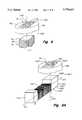
- FIG. 6shows an isometric representation of an embodiment of an imaging guidewire according to the present invention, showing the transducer in a slab-shaped stage.
- FIG. 7shows a sectional view along line 7--7 of FIG. 6.
- FIG. 8shows an exploded view in portion of the microactuator of an imaging guidewire according to the present invention, showing an electromagnet.
- FIG. 9Ashows an exploded view in portion of the microactuator of another imaging guidewire according to the present invention, showing an electromagnet.
- FIG. 9Bshows an exploded view in portion of the microactuator of another imaging guidewire according to the present invention, showing an electromagnet with a core having a finger.
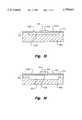
- FIG. 10shows a sectional view of layers of material during the formation of an embodiment of a stage in the fabrication of the microactuator of an imaging guidewire according to the present invention.
- FIG. 11shows a sectional view of layers of material during the formation of an embodiment of a stage in the fabrication of the microactuator of an imaging guidewire according to the present invention, showing the preparation of patterning a layer of magnetic material.
- FIG. 12shows a sectional view of layers of material during the formation of an embodiment of a stage in the fabrication of the microactuator of an imaging guidewire according to the present invention, showing a layer of magnetic material formed.
- FIG. 13shows a sectional view of layers of material during the formation of an embodiment of a stage in the fabrication of the microactuator of an imaging guidewire according to the present invention, showing the formation of a cavity in which the transducer assembly can move pivotally.
- FIG. 14shows a sectional view of layers of material during the formation of an embodiment of a stage in the fabrication of the microactuator of an imaging guidewire according to the present invention, showing a transducer disposed on the plate.
- FIG. 15shows a sectional view of an embodiment of a stage in the imaging guidewire according to the present invention, showing the plate being pivoted to face a first direction.
- FIG. 16shows a sectional view of an embodiment of a stage in the imaging guidewire according to the present invention, showing the plate being pivoted to face a second direction.
- FIG. 17shows a sectional view of another embodiment of a stage in the imaging guidewire according to the present invention, showing a flap that is supported at the flap's end.
- FIG. 18is a schematic representation of a plan view of a stage according to the present invention, showing a gimbaled transducer assembly.
- FIG. 19is a schematic representation of a stage and an electrostatic actuation system according to the present invention.
- FIG. 20shows a schematic representation of an embodiment of the guidewire of the present invention having two transducers and flexible coil near the distal tip.
- the present inventionprovides an imaging guidewire that has an actuating mechanism proximate to the guidewire's tip, which is insertable into a patient's body. With the actuating mechanism at the tip, a long mechanical-energy-transferring system for transferring energy from a motor or a similar mechanical actuator outside the body is obviated. Thus, there is no need for cumbersome features such as cables for mechanically turning the transducer in 360° cycles in a protective shell or sheath.
- the guidewireis a special application of the ultrasonic probe disclosed in copending application Ser. No. 08/657,742 (filed May 31, 1996 by the same inventors as the present application), which is incorporated by reference in its entirety herein.
- FIG. 1An exemplary imaging guidewire of the present invention is schematically shown in FIG. 1.
- the guidewire 100has a distal end portion 102 for inserting into the patient's body cavity, e.g., an artery, and an proximal end 103 for the medical worker to control the operation of the guidewire. Between the distal end portion 102 and the proximal end 103 is an elongated main body 104.
- the elongated body 104is connected to an "imaging head" 106 at the imaging guidewire's distal end 108.
- the term "distal" end of the imaging guidewirerefers to the end that can be inserted into a patient's body cavity, e.g., the lumen of a blood vessel.
- body cavityrefers to a hollow area generally surrounded by walls, although the hollow area is not necessarily entirely enclosed. Further, it is not limited to readily accessible cavities such as the oral cavity, the rectum, and the like.
- a blood vesselis used as an example for the body cavity in which the imaging guidewire can be used.
- the present inventioncan be adapted for use in a variety of body cavities, such as a chamber in the heart, esophagus, stomach, intestine, abdominal cavity, bladder, uterus, and the like.
- FIG. 2shows how the imaging guidewire 100 is deployed in a blood vessel 112.
- the imaging head 106contains an ultrasound-emitting assembly which includes a transducer and the actuating mechanism for moving the transducer to scan an ultrasonic beam in the blood vessel 112.
- the ultrasonic beamis consisted of pulses.
- the proximal end 103which is remote to the distal end 108, is electrically connected to an ultrasound controller 114 (see FIG. 1) that controls the emission and reception of ultrasound, as well as steering the ultrasound-emitting assembly.
- This controller 114can also have the capability to analyze the electronic signals transmitted from the imaging guidewire as a result of ultrasound signals received by the imaging head 106.
- the controller 114can further store and display data. In this case, computers, CRT monitors, and the like, can be present in the controller 114.
- proximal end 103is detachable from the controller so as to facilitate inserting the guidewire to a desired position in the body cavity.
- An elongated sheath 116is shown surrounding a significant portion of the elongated body 104 of the imaging guidewire 100.
- Such a sheathcan be inserted into the body cavity after the guidewire has been placed in the desired location.
- Such a sheathcan be used for introducing various objects, e.g., angiographic catheter, pacing catheters, cutting tools for atherectomy, etc., into the body cavity.
- structure 116can also be, e.g., a catheter itself.
- an imaging ultrasonic probethat is not a guidewire can be made, based on the present disclosure, by a person skilled in the art.
- a non-guidewire ultrasonic probecan be introduced by means of a sheath or a guidewire into the body cavity.
- FIG. 3Ashows further details of a portion of an embodiment of the imaging guidewire (labeled as 100A in FIG. 3A) at the distal end 108.
- the elongated body 104 of the imaging guidewire 100Ahas a tubular wall 121 connected to the imaging head 106.
- the imaging head 106has a housing 122, for enclosing and protecting a microactuator 120A with a pivotable transducer assembly 124A for emitting and receiving ultrasonic signals.
- the housing 122is substantially acoustically transparent (or sonolucent) to ultrasound emitted by the transducer assembly 124A. Alternatively, depending on the application, the housing 122 can have a window for emitting and receiving ultrasound.
- a support 126is located proximal to and supports the microactuator 120A in rigid relation to the housing 122 and the wall 121, except when the flexible nature of the wall is considered.
- the imaging guidewirehas an imaginary center line extending longitudinally along the elongated body 104.
- the center line of the imaging guidewire near the imaging head 106is essentially a straight line and coincides with the longitudinal axis 123 of the distal portion of the imaging guidewire 100A.
- the transducer 144(see FIG. 6) is located laterally from the microactuator 120A. As used herein, "laterally” refers to a positional relationship in a direction radial to the axis 123 of the imaging guidewire.
- a liquid 127is contained in the housing 122. The liquid 127 matches the ultrasonic impedance of the housing 122 to reduce reverberations that damp the pivoting action of the microactuator 120A.
- the support 126can also form a liquid-tight seal with the housing 122 to contain the liquid, although it can also be nonliquid-tight so as to allow infusion of fluid from the proximal end to the chamber defined by the housing 122.
- the transducer assembly 124Ais generally planar and its normal points generally perpendicularly to the axis 123 of the imaging guidewire 100A. As the transducer assembly 124A emits an ultrasonic beam, the microactuator 120A rocks the transducer assembly 124A to sweep the ultrasonic beam in a plane perpendicular to the axis 123, as shown in FIG. 3B. The sweeping motion of the ultrasonic beam is shown by the two-headed arrow E.
- the transducer and the microactuatorare arranged such that the ultrasonic beam sweeps out a plane parallel to the axis 123.
- the sweeping path of the ultrasonic beamis shown by the symbol ⁇ , marked by F, going into the page in FIG. 3C.
- the wires for exciting the transducer on the transducer assembly 124A and the microactuatorare located along a cable 129 inside the tubular wall 121 (see FIG. 3A).
- a relative stiff yet flexible wire core 128contacts the support 126 for inserting and urging the guidewire into the body cavity.
- the wire core 128is attached to the support 126 to facilitate the insertion.
- the core 128 and the cablecan be combined, e.g., the core 128 can be the core of a coaxial cable and the outside conductor of the coaxial cable can be connected to ground.
- the guidewire 100has the usual structures that enable a guidewire to function well.
- the tubular wall 121 of the guidewireincludes coils to enable the guidewire to be flexible.
- Exemplary methods of making, methods of using, and structures of guidewiresare described in, e.g., U.S. Pat. No. 5,517,989 (Frisbie et al.), U.S. Pat. No. 5,497,782 (Fugoso), U.S. Pat. No. 5,520,189 (Malinowski et al.), and U.S. Pat. No. 5,546,948 (Hamm et al.). The description on guidewires in these documents are incorporated by reference herein.
- the guidewire's distal portionis shown in FIG. 4, the transducer in the transducer assembly 124B is affixed distally to the microactuator 120B, thereby providing a way to scan axially, i.e., the scan angle can have a median generally along the axis 123 of the imaging guidewire.
- a transducer assembly 124Cis supported proximate to the distal end 108 of the imaging guidewire 100C along the guidewire's axis 123.
- a transducer 124Cemits an ultrasonic beam axially toward the proximal end.
- the microactuator 120C and a pivotable reflector 130are mounted at a slanted angle to the axis 123 of the imaging guidewire such that the reflector reflects the axially-directed ultrasonic beam in a radial direction. As the reflector 130 pivots, it sweeps the ultrasonic beam to locations lateral to the imaging guidewire 100C, thereby scanning the wall of the blood vessel 112 lateral to the imaging guidewire.
- FIG. 6shows a stage 132 of the imaging guidewire according to the present invention in more detail.
- FIG. 7shows a sectional view of the stage 132 along the line 7--7 in FIG. 6.
- the stage 132is generally slab-shaped.
- the term "stage”refers to the structure that includes the substrate, plate, torsion arms, magnetic material, and the transducer, which will be described below.
- a cavity 133 in the stage 132is surrounded by walls 134A, 134B, 134C, 134D, on which are ledges 136A, 136B, 136C, 136D.
- a generally rectangular plate 138is supported on two opposing ledges 136A, 136C by two torsion arms 140A, 140C, one located about the mid point of each opposite edge of the stage 132.
- a plate 138whose thickness is much smaller than its other two dimensions, is balanced on the torsion arms 140A, 140C with the plate's center of gravity on an imaginary line joining the torsion arms.
- the torsion arms 140A, 140Care generally perpendicular to the thickness dimension. In this way, a minimal effort is needed to pivot, or turn, the plate on the torsion arms. If desired, the plate's center of gravity can be slightly off the torsion arms 140A, 140C without significantly affecting the performance of the imaging guidewire.
- transducer assemblyrefers to the structure including the plate, transducer, and magnetic material, if any.
- the twisting motion on torsion armsis considered to be "pivotal.” Because the torsion arms 140A, 140C are affixed to the walls of the stage 132, the plate 138 pivotally moves in a rocking, back and forth fashion, thereby enabling a sweeping scan by the transducer affixed on the plate.
- a ferromagnetic material 142e.g., a nickel ferrite (herein referred to as "NiFe") material, is layered on a surface of the plate 138, covering generally all of that surface. In this way, when a varying magnetic field is applied to the plate, the plate will pivot on the torsion arms instead of trying to move up and down as a whole. Due to the ease of fabrication, preferably, the magnetic material 142 is layered on the upper surface of the plate 138. As used herein, the "upper" surface refers to the surface that faces away from the cavity 133. If preferred, the magnetic material can be layered on the upper surface of the plate 138 on only one side of the torsion arms 140A, 140C, covering half of the surface.
- NiFenickel ferrite
- the transducer assembly 124includes the magnetic material 142 and a transducer 144 mounted on the upper surface of the plate 138.
- Electrical wires 146A, 146Cextend from transducer electrodes (not shown in the figures) to connection pads 148A, 148C.
- the connection pads 148A, 148Cin turn can be connected to electrical wires 150A, 150C to provide electrical energy to the transducer 144.
- one or more of the wires 146A, 146C, 150A, 150Ccan be replaced by appropriately doped channels in the torsion arms and frame of the stage, i.e., stage 132.
- the electrodesare connected to the surfaces of the transducer 144 to electrically generate and receive ultrasound by the piezoelectric effect. As the transducer 144 is excited and the plate 138 is pivoted by a varying magnetic field, the transducer radiates an ultrasonic beam to scan tissues in the blood vessel normal to the planar surface of the transducer.
- FIG. 8is an exploded view showing how the microactuator is located relative to the transducer.
- the microactuator 120Xcan be considered to include the stage 132 having the plate 138 (see FIG. 7) and torsion arms 140A, 140C, as well as the magnetic material 142 layered on the plate.
- the transducer assembly 124is moved by the pivotal movement of the plate 138 about the torsion arms 140A, 140C caused by variations of a magnetic field in which the magnetic material is situated.
- An electromagnet 154is proximate to the stage 132 to provide the varying magnetic field.
- the electromagnet 154contains a coil 156 that is wrapped around a magnet core 152. An electrical current can be passed through the coil 156 to produce a varying magnetic field.
- the magnet core 152 of the electromagnet 154extends parallel to, preferably along, the axis 123 of the imaging guidewire. This means that a long magnet core can be used to increased the number of turns of the coil, since the length of the electromagnet can extend along the axis 123 and is not limited by the diameter of the imaging guidewire in this embodiment.
- Such an actuatoris suitable for use in an imaging guidewire similar to that shown in FIG. 4.
- the coil 156is wrapped such that the axis of the coil is perpendicular to the plane of the stage 132 and the plate 138 is located generally at about the axis of the coil, which is parallel to the axis 123 of the imaging guidewire.
- the lines of the magnetic fieldpass through the plate 138 in a direction generally perpendicular to the plane of the stage 132.
- the stage 132can be affixed to the electromagnet 154 by commonly known affixing means, such as adhesive, clips, clamps, and the like.
- a tube 160 with an end plate 162can be used to anchor and protect the stage 132 and the electromagnet 154. It is noted that if a short magnet core is used so that the electromagnet and the stage 132 can fit transversely inside the imaging head 106, this arrangement of the plate 138 with the electromagnet 154 is also applicable for an imaging guidewire of FIG. 3A
- FIG. 9Ashows an exploded view of another embodiment of a transducer assembly and a microactuator that is especially suitable for an imaging guidewire of FIG. 3A.
- the stage 132is generally similar to the stage 132 of FIG. 8.
- the electromagnet 154Yhas a U-shaped magnet core 152Y.
- the magnet core 152Yhas an elongated magnet core body 155A with a first leg 155B and a second leg 155C extending about perpendicularly from its ends.
- the first leg 155Bis more distal than the second leg 155C in the imaging guidewire.
- a coil 156Yis wrapped around the magnet core 158Y.
- the axis of the coilis generally parallel to the axis 123 of the imaging guidewire so that a long electromagnet can be used.
- the stage 132is proximate to and preferably rests on the first leg 155B at the distal end of the imaging guidewire. In this way, the lines of the magnetic field in the electromagnet 154Y are channeled from the elongated magnet core body 155A and pass out of the first leg 155B through the stage 132.
- the electromagnet's magnetic fieldvaries and pivots the plate on the torsion arms 140AY and 140CY.
- the electromagnet 154Ycan be positioned proximate to or affixed to the stage 132.
- An alternative to a U-shaped magnet coreis a L-shaped magnet core, which still allows the stage 132 to be placed on the leg at the distal end of the magnet core.
- the electromagnet with a U-shaped magnet core or a L-shaped magnet corecan also be used in an imaging guidewire of FIG. 5.
- the strength of the electromagnetcan be increased by increasing the number of loops in the coil, increasing the cross sectional area of the magnet core (and therefore the size of the loops), and increasing the current in the coil. Since the plate 138 (see FIG. 7 and FIG. 14) is small and only magnetic field lines passing through the magnetic material on the plate affect the pivotal motion, as shown in FIG. 9B in portion, to increase the effective magnetic field strength, the electromagnet 154Z can have a magnet core 152Z including a finger 158A extending from a larger body 158B. The larger body 158B of the magnet core allows the coil 156 to have larger loops. At the finger 158A, the magnetic field lines are concentrated to pass through the magnetic material on the plate 138.
- a spacer 159 having a void 159A for receiving the finger 158Acan be disposed between the larger body 158B of the magnet core and the stage 132 to help secure the stage to the electromagnet 154Z.
- the spacer 159can have planar dimensions generally similar to those of the stage 132.
- the stage 132 and the electromagnetcan be enclosed in the imaging head 106 without enlarging the radial dimension of the imaging head.
- Methods of making coils and electromagnets for microactuatorsare known in the art. Some methods involve using a metallic coil, e.g., by deposition, and some involve doping a silicon material to form the conductive coil for the electromagnet. See, e.g., Wagner et al., "Microactuators with Moving Magnets for Linear, Torsional or Multiaxial Motion," Sensors and Actuators, A. 32, 1992, pp. 598-603; Kamins, et al., "Diffusion of Impurities in Polysilicon," J. Appl.
- more than one transducercan be present in the imaging head 106.
- more than one stageeach positioned such that the transducer thereon directs an ultrasonic beam at a different direction, can be present. This can be done, for example, by combining the transducer assemblies of FIG. 3A and FIG. 4.
- microactuator and the transducer assemblycan be made by adopting micromachining methods for semiconductors known in the art, e.g., Judy and Muller, "Magnetic Microactuation of Torsional Polysilicon structures," Dig. Int. Conf Solid-State Sensors and Actuators, Swiss, Sweden, Jun. 25-29, 1995, pp. 332-339; Ahn and Allen, "A Fully Integrated Micromagnetic Actuator with a Multilevel Meander Magnetic Core,” Tech. Dig. IEEE Solid-State Sensor and Actuator Workshop, (Hilton Head '92), Hilton Head Island, S.C., Jun. 22-25, 1992, pp.
- FIGS. 10 to 14show how such micromachining can be done using a silicon substrate; a sacrificial layer made of, e.g., silicon dioxide (SiO 2 ) or glass; a plate and torsion arms made of, e.g., polysilicon or silicon nitride (Si 3 N 4 ); and on the plate a layer of magnetic material, e.g., nickel ferrite (herein referred to as NiFe) permalloy consisting of 80% nickel and 20% iron. In scientific literature, this material with 80% nickel and 20% iron is sometimes represented by Ni 80 Fe 20 . It is noted that other magnetic materials can also be used, as long as it can be attracted by the electromagnet to pivot the plate.
- NiFenickel ferrite
- a substrate with a thickness about the desired thickness of a stage 132is provided.
- a layer 170 of sacrificial materiale.g., silicon dioxide, is deposited on the substrate 168, followed by a grown film 172 of either polysilicon or silicon nitride.
- the layer of magnetic materiale.g., NiFe, is deposited on the polysilicon or silicon nitride layer.
- selected portions of the magnetic materiale.g., NiFe 178
- seed layer 174, plate material, and sacrificial layer 170are removed to form the plate 138 and torsion arms 140A, 140C.
- substrate 168sacrificial material 170, plate material 172, and magnetic material (e.g., NiFe 178) are known in the art. Further selective etching of the silicon substrate 168 will allow the formation of a cavity 133.
- polyimidee.g., PI-2611 from DuPont Company (Wilmington, Del.).
- a polyimide layeris typically formed by spinning. Such a layer can be etched by dry plasma etching.
- Polyimide materials suitable for such applicationsare available commercially from chemical suppliers such as DuPont Company and Ciba Geigy Corp. (Greensboro, N.C.). Methods of spinning and etching a polyimide layer are known in the art. See, e.g., Ahn, et al., "A Planar Variable Reluctance Magnetic Micromotor with Fully Integrated Stator And Wrapped Coils," Proc.
- transducer-support layersince the support arms and the bottom layer of the transducer assembly are formed from such layers.
- stage 132 of the present inventionan embodiment that includes a silicon substrate layer, a SiO 2 sacrificial layer, a silicon nitride plate with torsion arms, and a magnetic material layer of NiFe is described below.
- glass and SiO 2can be etched with suitable chemicals, e.g., buffered hydrofluoric acid (HF) mixtures; silicon can be etched with potassium hydroxide (KOH) or tetramethyl ammonium hydroxide (TMAH); glass, SiO 2 , polysilicon, and silicon nitride can be dry-etched with plasma chemistry known to one skilled in the art; and silicon nitride can also be wet-etched with phosphoric acid (H 3 PO 4 ). It is also known that these etching methods affect each material (e.g., silicon, silicon nitride, polysilicon, SiO 2 , NiFe) differently. This difference is due to the materials' inherent physical and chemical properties. The different etch rates for such materials using a wide variety of etchants will allow the ability to etch differentially one material quickly and another very slowly.
- suitable chemicalse.g., buffered hydrofluoric acid (HF) mixtures
- siliconcan be etched with potassium hydroxide (KOH)
- layers of materials shown in FIG. 10, including silicon nitride 172, SiO 2 170, and silicon 168, but less the conductive seed film 174can be considered.
- the Silicon nitride layer 172can be lithographically masked and patterned with hot H 3 PO 4 at about 50° C. The acid will etch completely through the exposed silicon nitride areas relatively quickly but the etch rate will slow down considerably, i.e., in orders of magnitude, on the exposed SiO 2 layer 170.
- the lithographic masking material on top of the silicon nitride layercan be removed by an oxygen plasma with minimal effect on the exposed SiO 2 layer 170. Neither will the oxygen plasma affect the exposed silicon nitride layer.
- the lithographic masking material on the silicon nitridehas been removed and the opening in the silicon nitride layer exposes a thin layer of SiO 2 .
- a brief characterized timed dip, e.g., of about 10 seconds, in a 10:1 hydrofluoric acidwill remove the exposed SiO 2 layer 170.
- the final silicon substrate 168is now exposed.
- a final KOH or TMAH etchcan be used to etch the silicon substrate 168.
- the proper dilutions at the proper temperaturewill minimally affect the SiO 2 layer 170 and the silicon nitride layer 172.
- Proper timed exposure of the materials to TMAH or hot KOHwill result in a silicon etched cavity approximately defined by the silicon nitride 172 and SiO 2 170 opening. This general process methodology will be applied to fabricate the structures of interest.
- Etching methods for various materials used in solid state semiconductor technologyare known in the art. For example, methods for etching silicon dioxide are described in Steinbruchel et al., "Mechanism of dry etching of silicon dioxide--A case study of direct reactive ion etching," J. Electrochem. Soc. Solid-state and Technology, 132(1), pp. 180-186, January 1985; and Tenney et al., "Etch Rates of Doped Oxide in Solutions of Buffered HF,” J. Electrochem. Soc. Solid State and Technology, 120 (8), pp. 1091-1095, August 1973.
- Polysilicon etchingis described by Bergeron et al., "Controlled Anisotropic Etching of Polysilicon,” Solid State Technologies, August 1982, pp. 98-103; and B. L. Sopori, "A New Defect Etch for Polycrystalline Silicon,” J. Electrochem. Soc. Solid State and Technology, 1984. Silicon nitride etching is described by van Gelder et al., “The etching of Silicon Nitride in Phosphoric Acid with Silicon Dioxide as a mask", J. Electrochem. Soc. Solid State and Technology, 114 (8), August 1967, pp. 869-872. Silicon etching is described by M. J.
- a SiO 2 sacrificial layer 170 of a desired shape, size, thickness, and patternis formed on a silicon substrate 168.
- the sacrificial layer 170is covered with a transducer-support (Si 3 N 4 ) layer 172.
- This Si 3 N 4 layer 172is then covered with a photoresist, masked, and etched to form the desired size, shape, and pattern suitable to support the magnetic material and the transducer and to withstand the rigor of repeated torsional turning of the torsional arms during operation.
- a conductive seed film 174e.g., containing a chromium film and a copper film, is then vapor deposited on the selected surface on the Si 3 N 4 layer 172 to facilitate the deposition of the magnetic material.
- a layer of photoresist 176is used to cover areas of the Si 3 N 4 layer 172 on which deposition of magnetic material is not desired.
- a NiFe layer 178 of the desired thicknessis then electroplated on the portion of the Si 3 N 4 layer 172, i.e., on the conductive seed film 174, not covered by the photoresist 176.
- FIG. 12after removal of the photoresist and the conductive seed film 174 in selected areas, a NiFe layer of the desired size, thickness, and shape remains on the Si 3 N 4 layer 172.
- the sacrificial layer 170 beneath the portion of the Si 3 N 4 layer 172 which is designated to be the plate 138 and the torsion armsis etched by HF.
- the desired silicon substrate areais exposed.
- This exposed silicon substrate area in the silicon substrate 168can be etched with a KOH etching solution or TMAH solution to add depth to the cavity 133A.
- the cavity 133is formed.
- a transducer 144can then be affixed on the plate 138.
- the connection pads 148A, 148C and wires 146A, 146Ccan be used to interface the transducer via cabling 150A, 150C to the controller 114.
- the size, shape, thickness, and other dimensional characteristics of the microactuator and the transducercan vary to adapt to the application.
- an intravascular imaging guidewirewill have dimensions much smaller than those of an endoscopic imaging guidewire.
- the substrate 168generally can have a thickness of about 100 to 700 ⁇ m, preferably about 400 to 500 ⁇ m.
- the plate 138is preferably rectangular and have a thickness of about 2000 to 10,000 ⁇ , preferably about 4,000 to 9,000 ⁇ .
- the plate 138can have a width of about 0.2 to 0.7 mm, preferably about 0.3 to 0.4 mm, and a length of about 0.2 to 2 mm, preferably about 0.5 to 1 mm to provide an adequate surface to support the transducer.
- the torsion arms 140A, 140Care preferably relatively short compared to the width of the plate so as to result in less stress due to the weight of the plate. However, the torsion arms 140A, 140C should be sufficiently long to allow the pivotal motion of the plate 138 to sweep over a desired angle, which corresponds to the angle swept by the normal of the plate. This angle is less than 180° and typically about 10° to 90°. It preferably is about ⁇ 45° with respect to the normal of the plate.
- the width of the plate 138not be excessive such that the plate does not strike the base of the cavity 133.
- a wider platewould also require a larger force to turn the plate 138 on the torsion arms 140A, 140C and result in a slower sweep cycle.
- the plate 138can vary from a square shape to a rectangular shape with a width (i.e., the side perpendicular to the torsion arms) to length ratio of about 1:3 to 1:1, preferably about 1:2.
- the lengthis parallel to the torsional arms 140A, 140C to decrease the force needed to pivot the plate.
- the magnetic materialis preferably deposited on the upper surface of the plate 138 on both sides of the torsion arms 140A, 140C.
- the layer of magnetic materiale.g. NiFe layer 178 is formed such that the N pole is on one side and the S pole is on the other side of the torsion arms 140A, 140C on the surface of the plate 138
- a pole of the electromagnetsee, e.g., FIG. 8, electromagnet 154)
- the magnetic materialoccupies substantially all of the upper surface of the plate. Its thickness is preferably less than 25% that of the plate, i.e., the Si 3 N 4 layer.
- the pole of the electromagnetcan be placed under one side of the plate 138.
- Another way of actuationis to form the magnetic material on the plate 138 such that the one pole (e.g., the N pole) is on top and the opposite pole is on the bottom and place two poles of an electromagnet each under a different half of the plate.
- the transducer 144covers substantially all of the upper surface of the magnetic material 178 and that of the plate 138 (which is not covered by the magnetic material), to use the plate's surface efficiently.
- the transducer 144has the usual electrodes, wires and transducer element, as known in the art for a transducer in imaging guidewires.
- Methods of making small transducers for intrabody-cavity applications, such as intravascular applications,are known in the art.
- an intravascular imaging guidewirecan have a silicon substrate layer about 500 ⁇ m thick.
- the Si 3 N 4 platecan be about 9,000 ⁇ thick, 400 ⁇ m wide, and about 1,000 ⁇ m long.
- the NiFe layer 178can be about 10 ⁇ m thick and covers essentially all of the upper surface of the plate.
- the transducercan be made of a layer of piezoelectric material (e.g., PZT lead zirconium titanate.) of about 80 ⁇ m thick, a quarter-wave matching layer of graphite about 40 ⁇ m thick, and a thick backing material of epoxy and tungsten about 300 ⁇ m thick. It can cover essentially all of the upper surface of the plate, therefore covering the NiFe as well.
- the transducermay also be of quarter-wave material with an appropriate matching layer material such as graphite. Both acoustic matching and backing techniques for making transducers, as well the applicable materials, are known in the art.
- the combined thickness of the transducer, the magnetic material, the sacrificial layer, and the plateis thin compared to the length and width thereof.
- the combined structureis still generally plate-shaped.
- the torsion arms 140A, 140Ccan each be about 5 to 20 ⁇ m long.
- the substrate 168can have a thickness of about 400 to 500 ⁇ m. This will accommodate a cavity 133 of about 300 to 400 ⁇ m deep.
- the sacrificial layer 170is very thin, generally about 150 to 500 ⁇ . Therefore, the stage 132 has about the same thickness as the substrate 168.
- the actuating mechanism and the stage 132 with the transducer assemblyare located in the housing 122, which is substantially transparent to ultrasound.
- the housingis preferably constructed to be mechanical sturdy and has a proper thickness to withstand being manipulated in the insertion process.
- the guidewires of the present inventionhas the usual structures that allows the proper function of typical guidewires, e.g., a core to facilitate urging the guidewire into the cavity, a low-friction surface on the main body suitable for a sheath to slide on and be guided to a desire location. Commonly known techniques can be used for making such structure.
- the actuating mechanism and the stagecan be made with the techniques disclosed in copending application entitled “Improved ultrasonic probe with back and forth sweeping ultrasonic source,” Docket No. 10961111-1, filed by Lum et al. on the same day as the present application.
- the techniques of the Lum et al. copending applicationare incorporated by reference herein.
- FIG. 15is a sectional view of the stage 132, with an orientation perpendicular to that of FIG. 14, showing the plate 138 being pivoted such that the plane of the plate forms an angle with the plane of the stage.
- This positioncan be achieved, for example, by passing an electrical current through the coil of the electromagnet to energize the electromagnet, thereby repelling one half and attracting the other half of the magnetic material layer 178.
- the transducer elemente.g., piezoelectric element
- ultrasonic pulsesare transmitted normal to the plane of the transducer, i.e., generally normal to the plane of the plate 138.
- the respective halves of the magnetic material layer 178are attracted and repelled by the electromagnet to pivot the plate 138 to a different angle relative to the plane of the stage 132.
- the transducer assembly 124rocks on the torsion arms such that the ends of the transducer assembly swing back and forth.
- the transducer assembly 124is swept through an angular range to scan tissues encircling the imaging guidewire.
- a way to bias the plate 138 such that the transducer assembly 124 can be at a desired position when no current passes through the coil of the electromagnetis to include a permanent magnet (not shown in the figures), for example, proximate to the magnetic material layer 178.
- the size and strength of the permanent magnetis selected such that the constant magnetic field of the permanent magnet exerts a continuous force to bias the plate 138 to a desired position.
- the imaging guidewiremay need to be moved periodically so as to move the imaging head (labeled as 106 in FIG. 1) to different locations or orientations. This can be done, for example, by advancing or retracting the imaging head along the longitudinal axis of the guidewire and by turning the imaging guidewire on the longitudinal axis.
- FIG. 17An alternative embodiment of the imaging guidewire of the present invention, shown in FIG. 17, includes a flap 138Z linked and supported at one end by support arm(s) 140Z to a wall 134Z surrounding a cavity 133Z.
- This flap 138Zfunctions similarly to the plate 138 of FIG. 16 and supports a magnetic material layer 178Z and a transducer 144Z.
- Such a devicecan be made, for example, with the method described in Liu, et al. (1995), supra or the method described by Judy and Muller (1995), supra for making microactuators with supporting beams or cantilevers.
- a permanent magnetcan be used to bias the transducer assembly to a desired location when the electromagnet is not activated.
- a transducere.g., transducer 144
- the controller 114is used to control the emission of ultrasonic signals and analyze ultrasonic signals received.
- Systems for controlling, emission, reception, and analysis of ultrasonic signalsare known in the art.
- FIG. 18illustrates an embodiment in which the stage 132 has a gimbaled transducer assembly 124D in which the a first plate 138D and a second plate 138E each pivots about an axis 90° to each other.
- the plate 138Drocks on torsion arms 140D and 140D', causing the transducer assembly 124D to rock as a whole.
- a transducer subassembly 124Ewhich includes the second plate 138E, pivots on torsion arms 140E, 140E'.
- the transducer subassembly 124Ealso has a transducer 144 covering the upper surface thereof.
- the torsion arms 140D, 140D'are aligned with each other but are perpendicular to the torsion arms 140E, 140E', which are aligned with each other.
- a layer 142E of magnetic materialcan be deposited on the second plate 138E, a different pole on each side of the torsion arms 140E, 140E'.
- a layer of magnetic material 142Dcan be deposited on the first plate 138D outside the transducer subassembly 124E.
- the transducerBy applying magnetic fields to the transducer assembly 124D and the transducer subassembly 124E separately by means of electromagnets, the transducer can be pivoted to rock on torsion arms 140D, 140D' and on torsion arms 140E, 140E'.
- One way to apply magnetic fields separatelyis by means of an electromagnet that has two concentric coils such that the inner coil controls the magnetic field for the transducer subassembly 124E and the outer coil controls the magnetic field of the transducer assembly 124D while canceling out in whole or in part the magnetic field over the transducer subassembly.
- An alternative way to actuate the pivotal motion of the transducer on the torsion arms 140D, 140D' and on torsion arms 140E, 140E'is by electrostatically attracting different portions of the plates 138D and 138E by adapting the electrostatic mechanism depicted in FIG. 19, which is described below. This can be done, for example, by positioning a mesa under each half of the plates 138D and 138E and orchestrating the charging of each mesa to attract various portions of the plates.
- an imaging guidewirecan be made such that it can scan, i.e., to image, three-dimensionally without its head 106 (see FIGS. 1 and 2) being moved.
- the imaging guidewirewould have to be moved to different locations in the body cavity.
- electrostatic forcerefers to an attracting or repelling force resulting from the electric field of two charged bodies in proximity but not in contact.
- FIG. 19illustrates an example.
- the construction of the substrate 168, the sacrificial layer 170, the plate 138, and the transducer assembly 124are similar to that of FIG. 16 except that no magnetic material is deposited on the plate.
- a metallic conductive mesa 190Ae.g., made with Pd/Ag alloy, is affixed on the substrate 168 underneath the plate 138 on one side of the torsion arm 140.
- a second metallic conductive mesa 190Bis on the substrate on the other side of the torsion arm 140.
- An electrostatic driver 192Aapplies an electrostatic force, acting on the mesa 190A to pivot the plate 138.
- a control voltage V cdrives the transistor 194 by means of a control pulse.
- the control voltageis high, the transistor is saturated and the current in the inductor 196 reaches a steady-state value, which depends on the supply voltage, V + and the resistor R 1 .
- the control voltageis low, the transistor 194 is turned off and the inductor causes charge to be transferred through the diode and onto the mesa 190.
- the plate 138 and mesa 190Aact as plates of a capacitor and the electrostatic force between them causes them to be attracted to each other.
- the plate 138returns to its neutral position as charge bleeds off through leakage paths, whereupon the second mesa 190B on the opposite side attracts the plate in the opposite direction.
- the second mesa 190Bis controlled by a driver circuit 192B similar to electrostatic driver 192A such that the drivers coordinate to alternately attract their corresponding halves of the plate 138.
- V cthe applied control voltage
- the plate 138can be pivoted back and forth.
Landscapes
- Health & Medical Sciences (AREA)
- Life Sciences & Earth Sciences (AREA)
- Engineering & Computer Science (AREA)
- Medical Informatics (AREA)
- Biophysics (AREA)
- Nuclear Medicine, Radiotherapy & Molecular Imaging (AREA)
- Pathology (AREA)
- Radiology & Medical Imaging (AREA)
- Veterinary Medicine (AREA)
- Biomedical Technology (AREA)
- Heart & Thoracic Surgery (AREA)
- Physics & Mathematics (AREA)
- Molecular Biology (AREA)
- Surgery (AREA)
- Animal Behavior & Ethology (AREA)
- General Health & Medical Sciences (AREA)
- Public Health (AREA)
- Gynecology & Obstetrics (AREA)
- Ultra Sonic Daignosis Equipment (AREA)
Abstract
Description
Claims (23)
Priority Applications (4)
| Application Number | Priority Date | Filing Date | Title |
|---|---|---|---|
| US08/757,040US5779643A (en) | 1996-11-26 | 1996-11-26 | Imaging guidewire with back and forth sweeping ultrasonic source |
| DE1997109241DE19709241A1 (en) | 1996-05-31 | 1997-03-06 | Scanning ultrasound probe with locally driven wobble ultrasound source |
| JP9132279AJPH1085221A (en) | 1996-05-31 | 1997-05-22 | Ultrasonic probe |
| GB9710890AGB2313668B (en) | 1996-05-31 | 1997-05-27 | Scanning ultrasonic probe |
Applications Claiming Priority (1)
| Application Number | Priority Date | Filing Date | Title |
|---|---|---|---|
| US08/757,040US5779643A (en) | 1996-11-26 | 1996-11-26 | Imaging guidewire with back and forth sweeping ultrasonic source |
Publications (1)
| Publication Number | Publication Date |
|---|---|
| US5779643Atrue US5779643A (en) | 1998-07-14 |
Family
ID=25046109
Family Applications (1)
| Application Number | Title | Priority Date | Filing Date |
|---|---|---|---|
| US08/757,040Expired - Fee RelatedUS5779643A (en) | 1996-05-31 | 1996-11-26 | Imaging guidewire with back and forth sweeping ultrasonic source |
Country Status (1)
| Country | Link |
|---|---|
| US (1) | US5779643A (en) |
Cited By (74)
| Publication number | Priority date | Publication date | Assignee | Title |
|---|---|---|---|---|
| US6000198A (en)* | 1998-04-07 | 1999-12-14 | Calgon Carbon Corporation | Method and package for packaging contents at reduced pressures |
| US6013033A (en)* | 1995-02-01 | 2000-01-11 | Centre National De La Recherche Scientifique | Intracavitary echographic imaging catheter |
| US6110121A (en)* | 1999-01-25 | 2000-08-29 | Lenker; Jay Alan | Method and apparatus for obtaining improved resolution from intraluminal ultrasound |
| US6142958A (en)* | 1998-12-23 | 2000-11-07 | Radi Medical Systems Ab | Sensor and guide wire assembly |
| WO2001089598A3 (en)* | 2000-05-19 | 2002-03-14 | Bard Inc C R | Guidewire with viewing capability |
| US6368275B1 (en)* | 1999-10-07 | 2002-04-09 | Acuson Corporation | Method and apparatus for diagnostic medical information gathering, hyperthermia treatment, or directed gene therapy |
| US20020107447A1 (en)* | 1999-07-20 | 2002-08-08 | Scimed Life Systems, Inc. | Imaging catheter and methods of use for ultrasound-guided ablation |
| US6524333B1 (en)* | 1997-12-30 | 2003-02-25 | Lars Sunnanvader | Device for therapeutical treatment of a blood vessel |
| US20030092394A1 (en)* | 2000-05-26 | 2003-05-15 | Philip Gray | Test signalling |
| US6592526B1 (en) | 1999-01-25 | 2003-07-15 | Jay Alan Lenker | Resolution ultrasound devices for imaging and treatment of body lumens |
| US6659957B1 (en) | 1998-03-05 | 2003-12-09 | Gil M. Vardi | Optical-acoustic imaging device |
| US20030229286A1 (en)* | 1999-01-25 | 2003-12-11 | Lenker Jay A. | Resolution optical and ultrasound devices for imaging and treatment of body lumens |
| US6694603B1 (en)* | 1997-06-24 | 2004-02-24 | Seagate Technology Llc | Process of forming a magnetic microactuator |
| US20050171426A1 (en)* | 2002-05-02 | 2005-08-04 | Kononklijke Philips Electronics N.V. | Method for transcutaneous catheter guiding |
| US20050250783A1 (en)* | 2004-04-15 | 2005-11-10 | Johnson James A | Fused heterocyclic compounds |
| US20060030753A1 (en)* | 2004-08-09 | 2006-02-09 | Scimed Life Systems, Inc. | Fiber optic imaging catheter |
| WO2006110666A3 (en)* | 2005-04-12 | 2006-11-30 | Scimed Life Systems Inc | Forward looking imaging guidewire |
| US20070016055A1 (en)* | 2005-07-01 | 2007-01-18 | Scimed Life Systems, Inc. | Concave phased array imaging catheter |
| US20070116408A1 (en)* | 2005-11-22 | 2007-05-24 | Eberle Michael J | Optical imaging probe connector |
| US20070129628A1 (en)* | 2005-12-02 | 2007-06-07 | The Cooper Health System | Regional anesthetic method and apparatus |
| US7245789B2 (en) | 2002-10-07 | 2007-07-17 | Vascular Imaging Corporation | Systems and methods for minimally-invasive optical-acoustic imaging |
| US20070167829A1 (en)* | 2005-12-02 | 2007-07-19 | Robert Hirsh | Regional anesthetic method and apparatus |
| US20080065125A1 (en)* | 2000-12-20 | 2008-03-13 | Foxhollow Technologies, Inc. | High capacity debulking catheter with distal driven cutting wheel |
| US20080177138A1 (en)* | 2007-01-19 | 2008-07-24 | Brian Courtney | Scanning mechanisms for imaging probe |
| US20080178134A1 (en)* | 2007-01-19 | 2008-07-24 | Fujitsu Limited | Timing verification method and apparatus |
| US7473224B2 (en) | 2001-05-29 | 2009-01-06 | Ethicon Endo-Surgery, Inc. | Deployable ultrasound medical transducers |
| US7473250B2 (en) | 2004-05-21 | 2009-01-06 | Ethicon Endo-Surgery, Inc. | Ultrasound medical system and method |
| US20090131798A1 (en)* | 2007-11-19 | 2009-05-21 | Minar Christopher D | Method and apparatus for intravascular imaging and occlusion crossing |
| US20090264768A1 (en)* | 2007-01-19 | 2009-10-22 | Brian Courtney | Scanning mechanisms for imaging probe |
| US20090264771A1 (en)* | 2008-04-22 | 2009-10-22 | Medtronic Vascular, Inc. | Ultrasonic Based Characterization of Plaque in Chronic Total Occlusions |
| US20100087732A1 (en)* | 2008-10-02 | 2010-04-08 | Vascular Imaging Corporation | Optical ultrasound receiver |
| US20100249604A1 (en)* | 2009-03-31 | 2010-09-30 | Boston Scientific Corporation | Systems and methods for making and using a motor distally-positioned within a catheter of an intravascular ultrasound imaging system |
| US20100249599A1 (en)* | 2009-03-31 | 2010-09-30 | Boston Scientific Scimed, Inc. | Systems and methods for making and using an imaging core of an intravascular ultrasound imaging system |
| US20100249603A1 (en)* | 2009-03-31 | 2010-09-30 | Boston Scientific Scimed, Inc. | Systems and methods for making and using a motor distally-positioned within a catheter of an intravascular ultrasound imaging system |
| US7806839B2 (en) | 2004-06-14 | 2010-10-05 | Ethicon Endo-Surgery, Inc. | System and method for ultrasound therapy using grating lobes |
| US20100280316A1 (en)* | 2007-06-28 | 2010-11-04 | Dietz Dennis R | Catheter |
| US7846096B2 (en) | 2001-05-29 | 2010-12-07 | Ethicon Endo-Surgery, Inc. | Method for monitoring of medical treatment using pulse-echo ultrasound |
| US7901441B2 (en) | 2005-10-18 | 2011-03-08 | Boston Scientific Scimed, Inc. | Method of using an imaging catheter to conduct photodynamic procedures |
| US20110071400A1 (en)* | 2009-09-23 | 2011-03-24 | Boston Scientific Scimed, Inc. | Systems and methods for making and using intravascular ultrasound imaging systems with sealed imaging cores |
| US20110071401A1 (en)* | 2009-09-24 | 2011-03-24 | Boston Scientific Scimed, Inc. | Systems and methods for making and using a stepper motor for an intravascular ultrasound imaging system |
| US20110213300A1 (en)* | 2004-03-23 | 2011-09-01 | Boston Scientific Scimed, Inc. | In-vivo visualization system |
| US20110313340A1 (en)* | 2010-06-18 | 2011-12-22 | The Regents Of The University Of California | Unobstructing microdevices for self-clearing implantable catheters |
| US8192452B2 (en) | 2009-05-14 | 2012-06-05 | Tyco Healthcare Group Lp | Easily cleaned atherectomy catheters and methods of use |
| US8226674B2 (en) | 2000-12-20 | 2012-07-24 | Tyco Healthcare Group Lp | Debulking catheters and methods |
| US8246640B2 (en) | 2003-04-22 | 2012-08-21 | Tyco Healthcare Group Lp | Methods and devices for cutting tissue at a vascular location |
| US8285362B2 (en) | 2007-06-28 | 2012-10-09 | W. L. Gore & Associates, Inc. | Catheter with deflectable imaging device |
| US8328829B2 (en) | 1999-08-19 | 2012-12-11 | Covidien Lp | High capacity debulking catheter with razor edge cutting window |
| CN102949210A (en)* | 2011-08-25 | 2013-03-06 | 西门子公司 | Endoscopic device for minimum-invasive linear measurement |
| US8414604B2 (en) | 2008-10-13 | 2013-04-09 | Covidien Lp | Devices and methods for manipulating a catheter shaft |
| US8496677B2 (en) | 2009-12-02 | 2013-07-30 | Covidien Lp | Methods and devices for cutting tissue |
| US8597315B2 (en) | 1999-08-19 | 2013-12-03 | Covidien Lp | Atherectomy catheter with first and second imaging devices |
| US20140039277A1 (en)* | 2006-10-12 | 2014-02-06 | Theodore P. Abraham | Remote ultrasound assessment and intervention system |
| US8784440B2 (en) | 2008-02-25 | 2014-07-22 | Covidien Lp | Methods and devices for cutting tissue |
| US8808186B2 (en) | 2010-11-11 | 2014-08-19 | Covidien Lp | Flexible debulking catheters with imaging and methods of use and manufacture |
| US8852112B2 (en) | 2007-06-28 | 2014-10-07 | W. L. Gore & Associates, Inc. | Catheter with deflectable imaging device and bendable electrical conductor |
| US8920450B2 (en) | 2010-10-28 | 2014-12-30 | Covidien Lp | Material removal device and method of use |
| US8992717B2 (en) | 2011-09-01 | 2015-03-31 | Covidien Lp | Catheter with helical drive shaft and methods of manufacture |
| US8998937B2 (en) | 1999-08-19 | 2015-04-07 | Covidien Lp | Methods and devices for cutting tissue |
| US9028512B2 (en) | 2009-12-11 | 2015-05-12 | Covidien Lp | Material removal device having improved material capture efficiency and methods of use |
| US9119662B2 (en) | 2010-06-14 | 2015-09-01 | Covidien Lp | Material removal device and method of use |
| US9320493B2 (en)* | 2014-07-08 | 2016-04-26 | Nadarasa Visveshwara | System and method for measuring fluidics in arteries |
| US9532844B2 (en) | 2012-09-13 | 2017-01-03 | Covidien Lp | Cleaning device for medical instrument and method of use |
| CN106794005A (en)* | 2014-07-08 | 2017-05-31 | 纳达拉萨·维斯费什瓦拉 | Systems and methods for measuring arterial fluids |
| US9687266B2 (en) | 2009-04-29 | 2017-06-27 | Covidien Lp | Methods and devices for cutting and abrading tissue |
| US9801647B2 (en) | 2006-05-26 | 2017-10-31 | Covidien Lp | Catheter including cutting element and energy emitting element |
| US9943329B2 (en) | 2012-11-08 | 2018-04-17 | Covidien Lp | Tissue-removing catheter with rotatable cutter |
| US10213224B2 (en) | 2014-06-27 | 2019-02-26 | Covidien Lp | Cleaning device for catheter and catheter including the same |
| US10292721B2 (en) | 2015-07-20 | 2019-05-21 | Covidien Lp | Tissue-removing catheter including movable distal tip |
| WO2019108722A1 (en)* | 2017-11-29 | 2019-06-06 | Avent, Inc. | System and method for mounting an ultrasound transducer on a needle |
| US10314664B2 (en) | 2015-10-07 | 2019-06-11 | Covidien Lp | Tissue-removing catheter and tissue-removing element with depth stop |
| US10314667B2 (en) | 2015-03-25 | 2019-06-11 | Covidien Lp | Cleaning device for cleaning medical instrument |
| CN111031924A (en)* | 2017-06-23 | 2020-04-17 | 奥拉尔戴格诺斯蒂克斯有限公司 | Transoral ultrasound probe and method of use |
| US10856837B2 (en)* | 2016-09-30 | 2020-12-08 | Robert Bosch Gmbh | Micro-mechanical adjustment system for piezoelectric transducers |
| US11819192B2 (en) | 2004-03-23 | 2023-11-21 | Boston Scientific Scimed, Inc. | In-vivo visualization system |
Citations (15)
| Publication number | Priority date | Publication date | Assignee | Title |
|---|---|---|---|---|
| US4794931A (en)* | 1986-02-28 | 1989-01-03 | Cardiovascular Imaging Systems, Inc. | Catheter apparatus, system and method for intravascular two-dimensional ultrasonography |
| US4899757A (en)* | 1988-02-22 | 1990-02-13 | Intertherapy, Inc. | Ultrasound imaging probe with zero dead space |
| US5000185A (en)* | 1986-02-28 | 1991-03-19 | Cardiovascular Imaging Systems, Inc. | Method for intravascular two-dimensional ultrasonography and recanalization |
| US5176141A (en)* | 1989-10-16 | 1993-01-05 | Du-Med B.V. | Disposable intra-luminal ultrasonic instrument |
| US5240003A (en)* | 1989-10-16 | 1993-08-31 | Du-Med B.V. | Ultrasonic instrument with a micro motor having stator coils on a flexible circuit board |
| US5271402A (en)* | 1992-06-02 | 1993-12-21 | Hewlett-Packard Company | Turbine drive mechanism for steering ultrasound signals |
| US5368035A (en)* | 1988-03-21 | 1994-11-29 | Boston Scientific Corporation | Ultrasound imaging guidewire |
| US5377685A (en)* | 1993-12-17 | 1995-01-03 | Baylis Medical Company, Inc. | Ultrasound catheter with mechanically steerable beam |
| US5497782A (en)* | 1994-04-28 | 1996-03-12 | Medtronic, Inc. | Lockable guidewire |
| US5505088A (en)* | 1993-08-27 | 1996-04-09 | Stellartech Research Corp. | Ultrasound microscope for imaging living tissues |
| US5507294A (en)* | 1995-01-17 | 1996-04-16 | Hewlett Packard Company | Ultrasound diagnostic probe having non-rotating acoustic imaging waveguide |
| US5509418A (en)* | 1995-01-17 | 1996-04-23 | Hewlett-Packard Co. | Ultrasound diagnostic probe having acoustically driven turbin |
| US5517989A (en)* | 1994-04-01 | 1996-05-21 | Cardiometrics, Inc. | Guidewire assembly |
| US5520189A (en)* | 1990-07-13 | 1996-05-28 | Coraje, Inc. | Intravascular ultrasound imaging guidewire |
| US5546984A (en)* | 1994-06-14 | 1996-08-20 | Hewlett-Packard Company | Bellows-type, low spillage, quick disconnect unit |
- 1996
- 1996-11-26USUS08/757,040patent/US5779643A/ennot_activeExpired - Fee Related
Patent Citations (15)
| Publication number | Priority date | Publication date | Assignee | Title |
|---|---|---|---|---|
| US5000185A (en)* | 1986-02-28 | 1991-03-19 | Cardiovascular Imaging Systems, Inc. | Method for intravascular two-dimensional ultrasonography and recanalization |
| US4794931A (en)* | 1986-02-28 | 1989-01-03 | Cardiovascular Imaging Systems, Inc. | Catheter apparatus, system and method for intravascular two-dimensional ultrasonography |
| US4899757A (en)* | 1988-02-22 | 1990-02-13 | Intertherapy, Inc. | Ultrasound imaging probe with zero dead space |
| US5368035A (en)* | 1988-03-21 | 1994-11-29 | Boston Scientific Corporation | Ultrasound imaging guidewire |
| US5176141A (en)* | 1989-10-16 | 1993-01-05 | Du-Med B.V. | Disposable intra-luminal ultrasonic instrument |
| US5240003A (en)* | 1989-10-16 | 1993-08-31 | Du-Med B.V. | Ultrasonic instrument with a micro motor having stator coils on a flexible circuit board |
| US5520189A (en)* | 1990-07-13 | 1996-05-28 | Coraje, Inc. | Intravascular ultrasound imaging guidewire |
| US5271402A (en)* | 1992-06-02 | 1993-12-21 | Hewlett-Packard Company | Turbine drive mechanism for steering ultrasound signals |
| US5505088A (en)* | 1993-08-27 | 1996-04-09 | Stellartech Research Corp. | Ultrasound microscope for imaging living tissues |
| US5377685A (en)* | 1993-12-17 | 1995-01-03 | Baylis Medical Company, Inc. | Ultrasound catheter with mechanically steerable beam |
| US5517989A (en)* | 1994-04-01 | 1996-05-21 | Cardiometrics, Inc. | Guidewire assembly |
| US5497782A (en)* | 1994-04-28 | 1996-03-12 | Medtronic, Inc. | Lockable guidewire |
| US5546984A (en)* | 1994-06-14 | 1996-08-20 | Hewlett-Packard Company | Bellows-type, low spillage, quick disconnect unit |
| US5507294A (en)* | 1995-01-17 | 1996-04-16 | Hewlett Packard Company | Ultrasound diagnostic probe having non-rotating acoustic imaging waveguide |
| US5509418A (en)* | 1995-01-17 | 1996-04-23 | Hewlett-Packard Co. | Ultrasound diagnostic probe having acoustically driven turbin |
Non-Patent Citations (52)
| Title |
|---|
| Ahn, et al., A Fully Integrated Micromagnetic Actuator with a Multilevel Meander Magnetic Core, 1992 IEEE, 0 7803 0456 X/92, pp. 14 18.* |
| Ahn, et al., A Fully Integrated Micromagnetic Actuator with a Multilevel Meander Magnetic Core, 1992 IEEE, 0-7803-0456-X/92, pp. 14-18. |
| Ahn, et al., A Planar Variable Reluctance Magnetic Micromotor with Fully Integrated Stator and Wrapped Coils, Proc. IEEE Micro Electro Mechanical Systems, For Lauderdale, FL, Feb. 7 10, 1993, pp. 1 16.* |
| Ahn, et al., A Planar Variable Reluctance Magnetic Micromotor with Fully Integrated Stator and Wrapped Coils, Proc. IEEE Micro Electro Mechanical Systems, For Lauderdale, FL, Feb. 7-10, 1993, pp. 1-16. |
| Bean, Anisotropic Etching of Silicon, IEEE Transactions on Electron Devices, vol. ED 25, No. 10, Oct. 1978, pp. 1185 1193.* |
| Bean, Anisotropic Etching of Silicon, IEEE Transactions on Electron Devices, vol. ED-25, No. 10, Oct. 1978, pp. 1185-1193. |
| Bergeron, et al., Controlled Anisotropic Etching of Polysilicon, Solid State Technology, Aug. 1982, pp. 98 103.* |
| Bergeron, et al., Controlled Anisotropic Etching of Polysilicon, Solid State Technology, Aug. 1982, pp. 98-103. |
| Declercq, A New C MOS Technology Using Anisotropic Etching of Silicon, IEEE Journal of Solid State Circuits, vol. SC 10, No. 4, Aug. 1975, pp. 191 196.* |
| Declercq, A New C-MOS Technology Using Anisotropic Etching of Silicon, IEEE Journal of Solid-State Circuits, vol. SC-10, No. 4, Aug. 1975, pp. 191-196. |
| Garabedian, et al., Microfabricated Surface Plasmon Sensing System, Sensors and Actuators A, 43 (1994), pp. 202 207.* |
| Garabedian, et al., Microfabricated Surface Plasmon Sensing System, Sensors and Actuators A, 43 (1994), pp. 202-207. |
| Guckel, et al., A First Functional Current Excited Planar Rotational Magnetic Micromotor, Proc. IEEE Micro Electro Mechanical Systems, Fort Lauderdale, FL, Feb. 7 10, 1993, pp. 7 11.* |
| Guckel, et al., A First Functional Current Excited Planar Rotational Magnetic Micromotor, Proc. IEEE Micro Electro Mechanical Systems, Fort Lauderdale, FL, Feb. 7-10, 1993, pp. 7-11. |
| Judy, et al., Batch Fabricated, Addressable, Magnetically Actuated Microstructures, Solid State Sensor and Actuator Workshop, Hilton Head, SC, Jun. 2 6, 1996, pp. 187 190.* |
| Judy, et al., Batch-Fabricated, Addressable, Magnetically Actuated Microstructures, Solid-State Sensor and Actuator Workshop, Hilton Head, SC, Jun. 2-6, 1996, pp. 187-190. |
| Judy, et al., Fabrication Processes for Magnetic Microactuators with Polysilicon Flexures, The 4th International Symposium on Magnetic Materials, Processes, and Devices, Chicago, IL, Oct. 8 13, 1995, 2 page paper.* |
| Judy, et al., Fabrication Processes for Magnetic Microactuators with Polysilicon Flexures, The 4th International Symposium on Magnetic Materials, Processes, and Devices, Chicago, IL, Oct. 8-13, 1995, 2-page paper. |
| Judy, et al., Magnetic Microactuation of Polysilicon Flexure Structures, Journal of Microelectromechanical Systems, vol. 4, No. 4, Dec. 1995, pp. 162 169.* |
| Judy, et al., Magnetic Microactuation of Polysilicon Flexure Structures, Journal of Microelectromechanical Systems, vol. 4, No. 4, Dec. 1995, pp. 162-169. |
| Judy, et al., Magnetic Microactuation of Torsional Polysilicon Structures, The 8th International Conference on Solid State Sensors and Actuators, Stockholm, Sweden, Jun. 25 29, 1995, pp. 332 335.* |
| Judy, et al., Magnetic Microactuation of Torsional Polysilicon Structures, The 8th International Conference on Solid-State Sensors and Actuators, Stockholm, Sweden, Jun. 25-29, 1995, pp. 332-335. |
| Kamins, et al., Diffusion of Impurities in Polycrystalline Silicon, J. Appl. Phys., vol. 43, No. 1, Jan. 1972, pp. 83 91.* |
| Kamins, et al., Diffusion of Impurities in Polycrystalline Silicon, J. Appl. Phys., vol. 43, No. 1, Jan. 1972, pp. 83-91. |
| Liu, et al., A Micromachined Permalloy Magnetic Actuator Array for Micro Robotics Assembly Systems, The 8th International Conference on Solid State Sensors and Actuators, and Eurosensors IX, Stockholm, Sweden, Jun. 25 29, 1995, pp. 328 331.* |
| Liu, et al., A Micromachined Permalloy Magnetic Actuator Array for Micro Robotics Assembly Systems, The 8th International Conference on Solid-State Sensors and Actuators, and Eurosensors IX, Stockholm, Sweden, Jun. 25-29, 1995, pp. 328-331. |
| Liu, et al., Out of Plane Permalloy Magnetic Actuators for Delta Wing Control, Proc. IEEE Micro Electro Mechanical Systems, Amsterdam, The Netherlands, Jan. 29 Feb. 3, 1995, pp. 7 12.* |
| Liu, et al., Out-of-Plane Permalloy Magnetic Actuators for Delta-Wing Control, Proc. IEEE Micro Electro Mechanical Systems, Amsterdam, The Netherlands, Jan. 29-Feb. 3, 1995, pp. 7-12. |
| Mandurah, et al., A Model for Conduction Inpolycrystalline Silicon Part 1: Theory, IEEE Transactions on Electron Devices, vol. ED 28, No. 10, Oct. 1981, pp. 1163 1170.* |
| Mandurah, et al., A Model for Conduction Inpolycrystalline Silicon--Part 1: Theory, IEEE Transactions on Electron Devices, vol. ED-28, No. 10, Oct. 1981, pp. 1163-1170. |
| Pister, et al., Microfabricated Hinges, Sensors and Actuators A, 33 (1992), pp. 249 256.* |
| Pister, et al., Microfabricated Hinges, Sensors and Actuators A, 33 (1992), pp. 249-256. |
| Richards, et al., Surface Plasmon Excitation Using a Polarization Preserving Optical Fiber and an Index Matching Fluid Optical Cell, Applied Optics, vol. 32, No. 16, Jun. 1, 1993, pp. 2901 2906.* |
| Richards, et al., Surface-Plasmon Excitation Using a Polarization-Preserving Optical Fiber and an Index-Matching Fluid Optical Cell, Applied Optics, vol. 32, No. 16, Jun. 1, 1993, pp. 2901-2906. |
| Robbins, et al., Chemical Etching of Silicon, Journal of the Electrochemical Society, vol. 107, No. 2, Feb. 1960, pp. 108 111.* |
| Robbins, et al., Chemical Etching of Silicon, Journal of the Electrochemical Society, vol. 107, No. 2, Feb. 1960, pp. 108-111. |
| Sopori, A New Defect Etch for Polycrystalline Silicon, J. Electrochem. Soc.: Solid State Science and Technology, vol. 131, No. 3, Mar. 1984, pp. 667 672.* |
| Sopori, A New Defect Etch for Polycrystalline Silicon, J. Electrochem. Soc.: Solid-State Science and Technology, vol. 131, No. 3, Mar. 1984, pp. 667-672. |
| Steinbruchel, et al., Mechanism of Dry Etching of Silicon Dioxide, J. Electrochem. Soc.: Solid State Science and Technology, vol. 132, No. 1, Jan. 1985, pp. 180 186.* |
| Steinbruchel, et al., Mechanism of Dry Etching of Silicon Dioxide, J. Electrochem. Soc.: Solid-State Science and Technology, vol. 132, No. 1, Jan. 1985, pp. 180-186. |
| Tabata, O., "PH-Controlled TMAH Etchants For Silicon Micromachining", 1996, Sensors and Actuators A, 53, pp. 335-339. |
| Tabata, O., PH Controlled TMAH Etchants For Silicon Micromachining , 1996, Sensors and Actuators A , 53, pp. 335 339.* |
| Tang, et al., Electrostatic Comb Drive of Lateral Polysilicon Resonators, Sensors and Actuators, A21 A23 (1990), pp. 328 331.* |
| Tang, et al., Electrostatic-Comb Drive of Lateral Polysilicon Resonators, Sensors and Actuators, A21-A23 (1990), pp. 328-331. |
| Tenney, et al., Etch Rates of Doped Oxides in Solutions of Buffered HF, J. Electrochem. Soc.: Solid State Science and Technology, vol. 120, No. 8, Aug. 1973, pp. 1091 1095.* |
| Tenney, et al., Etch Rates of Doped Oxides in Solutions of Buffered HF, J. Electrochem. Soc.: Solid-State Science and Technology, vol. 120, No. 8, Aug. 1973, pp. 1091-1095. |
| van Gelder, et al., The Etching of Silicon Nitride in Phosphoric Acid with Silicon Dioxide as a Mask, J. Electrochem. Soc.: Solid State Science, vol. 114, No. 8, Aug. 1967, pp. 869 872.* |
| van Gelder, et al., The Etching of Silicon Nitride in Phosphoric Acid with Silicon Dioxide as a Mask, J. Electrochem. Soc.: Solid-State Science, vol. 114, No. 8, Aug. 1967, pp. 869-872. |
| Wagner, et al., Microactuators with Moving Magnets for Linear, Torsional or Multiaxial Motion, Sensors and Actuators A, 32 (1992), pp. 598 603.* |
| Wagner, et al., Microactuators with Moving Magnets for Linear, Torsional or Multiaxial Motion, Sensors and Actuators A, 32 (1992), pp. 598-603. |
| Wagner, et al., Microfabricated Actuator with Moving Permanent Magnet, 1991 IEEE, CH2957 9/91/0000 0027, pp. 27 32.* |
| Wagner, et al., Microfabricated Actuator with Moving Permanent Magnet, 1991 IEEE, CH2957-9/91/0000-0027, pp. 27-32. |
Cited By (178)
| Publication number | Priority date | Publication date | Assignee | Title |
|---|---|---|---|---|
| US6013033A (en)* | 1995-02-01 | 2000-01-11 | Centre National De La Recherche Scientifique | Intracavitary echographic imaging catheter |
| US6694603B1 (en)* | 1997-06-24 | 2004-02-24 | Seagate Technology Llc | Process of forming a magnetic microactuator |
| US6524333B1 (en)* | 1997-12-30 | 2003-02-25 | Lars Sunnanvader | Device for therapeutical treatment of a blood vessel |
| US6659957B1 (en) | 1998-03-05 | 2003-12-09 | Gil M. Vardi | Optical-acoustic imaging device |
| US8926519B2 (en) | 1998-03-05 | 2015-01-06 | Vascular Imaging Corporation | Opitcal-acoustic imaging device |
| US7527594B2 (en) | 1998-03-05 | 2009-05-05 | Vascular Imaging Corporation | Optical-acoustic imaging device |
| US9532766B2 (en) | 1998-03-05 | 2017-01-03 | Vascular Imaging Corporation | Optical-acoustic imaging device |
| US20040082844A1 (en)* | 1998-03-05 | 2004-04-29 | Vardi Gil M. | Optical-acoustic imaging device |
| US6000198A (en)* | 1998-04-07 | 1999-12-14 | Calgon Carbon Corporation | Method and package for packaging contents at reduced pressures |
| US6336906B1 (en) | 1998-12-23 | 2002-01-08 | Radi Medical Systems Ab | Sensor and guide wire assembly |
| US6142958A (en)* | 1998-12-23 | 2000-11-07 | Radi Medical Systems Ab | Sensor and guide wire assembly |
| US6592526B1 (en) | 1999-01-25 | 2003-07-15 | Jay Alan Lenker | Resolution ultrasound devices for imaging and treatment of body lumens |
| US20090216125A1 (en)* | 1999-01-25 | 2009-08-27 | Lenker Jay A | Reslution optical & ultrasound devices for imaging and treatment of body lumens |
| US20030229286A1 (en)* | 1999-01-25 | 2003-12-11 | Lenker Jay A. | Resolution optical and ultrasound devices for imaging and treatment of body lumens |
| US7524289B2 (en) | 1999-01-25 | 2009-04-28 | Lenker Jay A | Resolution optical and ultrasound devices for imaging and treatment of body lumens |
| US8057395B2 (en) | 1999-01-25 | 2011-11-15 | Lenker Jay A | Resolution optical and ultrasound devices for imaging and treatment of body lumens |
| US6110121A (en)* | 1999-01-25 | 2000-08-29 | Lenker; Jay Alan | Method and apparatus for obtaining improved resolution from intraluminal ultrasound |
| US20020107447A1 (en)* | 1999-07-20 | 2002-08-08 | Scimed Life Systems, Inc. | Imaging catheter and methods of use for ultrasound-guided ablation |
| US7488289B2 (en)* | 1999-07-20 | 2009-02-10 | Boston Scientific Scimed, Inc. | Imaging catheter and methods of use for ultrasound-guided ablation |
| US10022145B2 (en) | 1999-08-19 | 2018-07-17 | Covidien Lp | Methods and devices for cutting tissue |
| US8328829B2 (en) | 1999-08-19 | 2012-12-11 | Covidien Lp | High capacity debulking catheter with razor edge cutting window |
| US8911459B2 (en) | 1999-08-19 | 2014-12-16 | Covidien Lp | Debulking catheters and methods |
| US8597315B2 (en) | 1999-08-19 | 2013-12-03 | Covidien Lp | Atherectomy catheter with first and second imaging devices |
| US8998937B2 (en) | 1999-08-19 | 2015-04-07 | Covidien Lp | Methods and devices for cutting tissue |
| US9615850B2 (en) | 1999-08-19 | 2017-04-11 | Covidien Lp | Atherectomy catheter with aligned imager |
| US9486237B2 (en) | 1999-08-19 | 2016-11-08 | Covidien Lp | Methods and devices for cutting tissue |
| US9532799B2 (en) | 1999-08-19 | 2017-01-03 | Covidien Lp | Method and devices for cutting tissue |
| US9788854B2 (en) | 1999-08-19 | 2017-10-17 | Covidien Lp | Debulking catheters and methods |
| US6368275B1 (en)* | 1999-10-07 | 2002-04-09 | Acuson Corporation | Method and apparatus for diagnostic medical information gathering, hyperthermia treatment, or directed gene therapy |
| WO2001089598A3 (en)* | 2000-05-19 | 2002-03-14 | Bard Inc C R | Guidewire with viewing capability |
| US20030092394A1 (en)* | 2000-05-26 | 2003-05-15 | Philip Gray | Test signalling |
| US8469979B2 (en) | 2000-12-20 | 2013-06-25 | Covidien Lp | High capacity debulking catheter with distal driven cutting wheel |
| US8052704B2 (en) | 2000-12-20 | 2011-11-08 | Foxhollow Technologies, Inc. | High capacity debulking catheter with distal driven cutting wheel |
| US8226674B2 (en) | 2000-12-20 | 2012-07-24 | Tyco Healthcare Group Lp | Debulking catheters and methods |
| US9241733B2 (en) | 2000-12-20 | 2016-01-26 | Covidien Lp | Debulking catheter |
| US20080065125A1 (en)* | 2000-12-20 | 2008-03-13 | Foxhollow Technologies, Inc. | High capacity debulking catheter with distal driven cutting wheel |
| US9005144B2 (en)* | 2001-05-29 | 2015-04-14 | Michael H. Slayton | Tissue-retaining systems for ultrasound medical treatment |
| US7846096B2 (en) | 2001-05-29 | 2010-12-07 | Ethicon Endo-Surgery, Inc. | Method for monitoring of medical treatment using pulse-echo ultrasound |
| US20130226040A1 (en)* | 2001-05-29 | 2013-08-29 | Slayton H. Michael | Tissue-Retaining Systems for Ultrasound Medical Treatment |
| US7473224B2 (en) | 2001-05-29 | 2009-01-06 | Ethicon Endo-Surgery, Inc. | Deployable ultrasound medical transducers |
| US20100312151A1 (en)* | 2001-05-29 | 2010-12-09 | Makin Inder Raj S | Tissue-retaining system for ultrasound medical treatment |
| US8333721B2 (en)* | 2001-05-29 | 2012-12-18 | Makin Inder Raj S | Tissue-retaining system for ultrasound medical treatment |
| US7806892B2 (en)* | 2001-05-29 | 2010-10-05 | Ethicon Endo-Surgery, Inc. | Tissue-retaining system for ultrasound medical treatment |
| US9261596B2 (en) | 2001-05-29 | 2016-02-16 | T. Douglas Mast | Method for monitoring of medical treatment using pulse-echo ultrasound |
| US7603159B2 (en)* | 2002-05-02 | 2009-10-13 | Koninklijke Philips Electronics N.V. | Method for transcutaneous catheter guiding |
| US20050171426A1 (en)* | 2002-05-02 | 2005-08-04 | Kononklijke Philips Electronics N.V. | Method for transcutaneous catheter guiding |
| US9339192B2 (en) | 2002-10-07 | 2016-05-17 | Vascular Imaging Corporation | Systems and methods for minimally-invasive optical-acoustic imaging |
| US7447388B2 (en) | 2002-10-07 | 2008-11-04 | Vascular Imaging Corporation | Systems and methods for minimally-invasive optical-acoustic imaging |
| US20100135111A1 (en)* | 2002-10-07 | 2010-06-03 | Vascular Imaging Corporation | Systems and methods for minimally-invasive optical-acoustic imaging |
| US8731340B2 (en) | 2002-10-07 | 2014-05-20 | Vascular Imaging Corporation | Systems and methods for minimally-invasive optical-acoustic imaging |
| US20090059727A1 (en)* | 2002-10-07 | 2009-03-05 | Vascular Imaging Corporation | Systems and methods for minimally-invasive optical-acoustic imaging |
| US8059923B2 (en) | 2002-10-07 | 2011-11-15 | Vascular Imaging Corporation | Systems and methods for minimally-invasive optical-acoustic imaging |
| US7660492B2 (en) | 2002-10-07 | 2010-02-09 | Vascular Imaging Corporation | Systems and methods for minimally-invasive optical-acoustic imaging |
| US7245789B2 (en) | 2002-10-07 | 2007-07-17 | Vascular Imaging Corporation | Systems and methods for minimally-invasive optical-acoustic imaging |
| US9192307B2 (en) | 2002-10-07 | 2015-11-24 | Vascular Imaging Corporation | Systems and methods for minimally-invasive optical-acoustic imaging |
| US8391652B2 (en) | 2002-10-07 | 2013-03-05 | Vascular Imaging Corporation | Systems and methods for minimally-invasive optical-acoustic imaging |
| US8246640B2 (en) | 2003-04-22 | 2012-08-21 | Tyco Healthcare Group Lp | Methods and devices for cutting tissue at a vascular location |
| US8961546B2 (en) | 2003-04-22 | 2015-02-24 | Covidien Lp | Methods and devices for cutting tissue at a vascular location |
| US9999438B2 (en) | 2003-04-22 | 2018-06-19 | Covidien Lp | Methods and devices for cutting tissue at a vascular location |
| US12213650B2 (en) | 2004-03-23 | 2025-02-04 | Boston Scientific Scimed, Inc. | In-vivo visualization system |
| US11064869B2 (en) | 2004-03-23 | 2021-07-20 | Boston Scientific Scimed, Inc. | In-vivo visualization system |
| US11819192B2 (en) | 2004-03-23 | 2023-11-21 | Boston Scientific Scimed, Inc. | In-vivo visualization system |
| US11832793B2 (en) | 2004-03-23 | 2023-12-05 | Boston Scientific Scimed, Inc. | Vivo visualization system |
| US8608649B2 (en) | 2004-03-23 | 2013-12-17 | Boston Scientific Scimed, Inc. | In-vivo visualization system |
| US20110213300A1 (en)* | 2004-03-23 | 2011-09-01 | Boston Scientific Scimed, Inc. | In-vivo visualization system |
| US9339173B2 (en) | 2004-03-23 | 2016-05-17 | Boston Scientific Scimed, Inc. | In-vivo visualization system |
| US7772232B2 (en) | 2004-04-15 | 2010-08-10 | Bristol-Myers Squibb Company | Quinazolinyl compounds as inhibitors of potassium channel function |
| US20050250783A1 (en)* | 2004-04-15 | 2005-11-10 | Johnson James A | Fused heterocyclic compounds |
| US7473250B2 (en) | 2004-05-21 | 2009-01-06 | Ethicon Endo-Surgery, Inc. | Ultrasound medical system and method |
| US7806839B2 (en) | 2004-06-14 | 2010-10-05 | Ethicon Endo-Surgery, Inc. | System and method for ultrasound therapy using grating lobes |
| US9132287B2 (en) | 2004-06-14 | 2015-09-15 | T. Douglas Mast | System and method for ultrasound treatment using grating lobes |
| US9215970B2 (en) | 2004-08-09 | 2015-12-22 | Boston Scientific Scimed, Inc. | Fiber optic imaging catheter |
| US10058236B2 (en) | 2004-08-09 | 2018-08-28 | Boston Scientific Scimed, Inc. | Fiber optic imaging catheter |
| US20110213206A1 (en)* | 2004-08-09 | 2011-09-01 | Boston Scientific Scimed, Inc. | Fiber optic imaging catheter |
| US20060030753A1 (en)* | 2004-08-09 | 2006-02-09 | Scimed Life Systems, Inc. | Fiber optic imaging catheter |
| US7922654B2 (en) | 2004-08-09 | 2011-04-12 | Boston Scientific Scimed, Inc. | Fiber optic imaging catheter |
| WO2006110666A3 (en)* | 2005-04-12 | 2006-11-30 | Scimed Life Systems Inc | Forward looking imaging guidewire |
| US8491484B2 (en) | 2005-04-12 | 2013-07-23 | Scimed Life Systems, Inc. | Forward looking imaging guidewire |
| US20070016055A1 (en)* | 2005-07-01 | 2007-01-18 | Scimed Life Systems, Inc. | Concave phased array imaging catheter |
| US7625343B2 (en) | 2005-07-01 | 2009-12-01 | Scimed Life Systems, Inc. | Concave phased array imaging catheter |
| US7901441B2 (en) | 2005-10-18 | 2011-03-08 | Boston Scientific Scimed, Inc. | Method of using an imaging catheter to conduct photodynamic procedures |
| US9557490B2 (en) | 2005-11-22 | 2017-01-31 | Vascular Imaging Corporation | Optical imaging probe |
| US9198581B2 (en) | 2005-11-22 | 2015-12-01 | Vascular Imaging Corporation | Optical imaging probe |
| US20070116408A1 (en)* | 2005-11-22 | 2007-05-24 | Eberle Michael J | Optical imaging probe connector |
| US20100014810A1 (en)* | 2005-11-22 | 2010-01-21 | Vascular Imaging Corporation | Optical imaging probe connector |
| US8320723B2 (en) | 2005-11-22 | 2012-11-27 | Vascular Imaging Corporation | Optical imaging probe connector |
| US8861908B2 (en) | 2005-11-22 | 2014-10-14 | Vascular Imaging Corporation | Optical imaging probe |
| US20110123154A1 (en)* | 2005-11-22 | 2011-05-26 | Vascular Imaging Corporation | Optical imaging probe connector |
| US7599588B2 (en) | 2005-11-22 | 2009-10-06 | Vascular Imaging Corporation | Optical imaging probe connector |
| US7881573B2 (en) | 2005-11-22 | 2011-02-01 | Vascular Imaging Corporation | Optical imaging probe connector |
| US20070129628A1 (en)* | 2005-12-02 | 2007-06-07 | The Cooper Health System | Regional anesthetic method and apparatus |
| US7645238B2 (en)* | 2005-12-02 | 2010-01-12 | The Cooper Health System | Regional anesthetic method and apparatus |
| US7931594B2 (en)* | 2005-12-02 | 2011-04-26 | The Cooper Health System | Regional anesthetic method and apparatus |
| US20070167829A1 (en)* | 2005-12-02 | 2007-07-19 | Robert Hirsh | Regional anesthetic method and apparatus |
| US10588653B2 (en) | 2006-05-26 | 2020-03-17 | Covidien Lp | Catheter including cutting element and energy emitting element |
| US11666355B2 (en) | 2006-05-26 | 2023-06-06 | Covidien Lp | Catheter including cutting element and energy emitting element |
| US9801647B2 (en) | 2006-05-26 | 2017-10-31 | Covidien Lp | Catheter including cutting element and energy emitting element |
| US20140039277A1 (en)* | 2006-10-12 | 2014-02-06 | Theodore P. Abraham | Remote ultrasound assessment and intervention system |
| US20080177138A1 (en)* | 2007-01-19 | 2008-07-24 | Brian Courtney | Scanning mechanisms for imaging probe |
| US20090264768A1 (en)* | 2007-01-19 | 2009-10-22 | Brian Courtney | Scanning mechanisms for imaging probe |
| WO2008086614A1 (en)* | 2007-01-19 | 2008-07-24 | University Health Network | Electrostatically driven imaging probe |
| US8460195B2 (en) | 2007-01-19 | 2013-06-11 | Sunnybrook Health Sciences Centre | Scanning mechanisms for imaging probe |
| US8214010B2 (en) | 2007-01-19 | 2012-07-03 | Sunnybrook Health Sciences Centre | Scanning mechanisms for imaging probe |
| US8784321B2 (en) | 2007-01-19 | 2014-07-22 | Sunnybrook Health Sciences Centre | Imaging probe with combined ultrasound and optical means of imaging |
| US7972272B2 (en) | 2007-01-19 | 2011-07-05 | University Health Network | Electrostatically driven image probe |
| US20080177183A1 (en)* | 2007-01-19 | 2008-07-24 | Brian Courtney | Imaging probe with combined ultrasounds and optical means of imaging |
| US8712506B2 (en) | 2007-01-19 | 2014-04-29 | Sunnybrook Health Sciences Centre | Medical imaging probe with rotary encoder |
| US20080178134A1 (en)* | 2007-01-19 | 2008-07-24 | Fujitsu Limited | Timing verification method and apparatus |
| US20080177139A1 (en)* | 2007-01-19 | 2008-07-24 | Brian Courtney | Medical imaging probe with rotary encoder |
| US8864675B2 (en) | 2007-06-28 | 2014-10-21 | W. L. Gore & Associates, Inc. | Catheter |
| US8285362B2 (en) | 2007-06-28 | 2012-10-09 | W. L. Gore & Associates, Inc. | Catheter with deflectable imaging device |
| US20100280316A1 (en)* | 2007-06-28 | 2010-11-04 | Dietz Dennis R | Catheter |
| US8852112B2 (en) | 2007-06-28 | 2014-10-07 | W. L. Gore & Associates, Inc. | Catheter with deflectable imaging device and bendable electrical conductor |
| US20090131798A1 (en)* | 2007-11-19 | 2009-05-21 | Minar Christopher D | Method and apparatus for intravascular imaging and occlusion crossing |
| US10219824B2 (en) | 2008-02-25 | 2019-03-05 | Covidien Lp | Methods and devices for cutting tissue |
| US8784440B2 (en) | 2008-02-25 | 2014-07-22 | Covidien Lp | Methods and devices for cutting tissue |
| US9445834B2 (en) | 2008-02-25 | 2016-09-20 | Covidien Lp | Methods and devices for cutting tissue |
| US20090264771A1 (en)* | 2008-04-22 | 2009-10-22 | Medtronic Vascular, Inc. | Ultrasonic Based Characterization of Plaque in Chronic Total Occlusions |
| US20100087732A1 (en)* | 2008-10-02 | 2010-04-08 | Vascular Imaging Corporation | Optical ultrasound receiver |
| US9579026B2 (en) | 2008-10-02 | 2017-02-28 | Vascular Imaging Corporation | Optical ultrasound receiver |
| US9078561B2 (en) | 2008-10-02 | 2015-07-14 | Vascular Imaging Corporation | Optical ultrasound receiver |
| US8560048B2 (en) | 2008-10-02 | 2013-10-15 | Vascular Imaging Corporation | Optical ultrasound receiver |
| US8414604B2 (en) | 2008-10-13 | 2013-04-09 | Covidien Lp | Devices and methods for manipulating a catheter shaft |
| US9192406B2 (en) | 2008-10-13 | 2015-11-24 | Covidien Lp | Method for manipulating catheter shaft |
| US10507037B2 (en) | 2008-10-13 | 2019-12-17 | Covidien Lp | Method for manipulating catheter shaft |
| US8298149B2 (en) | 2009-03-31 | 2012-10-30 | Boston Scientific Scimed, Inc. | Systems and methods for making and using a motor distally-positioned within a catheter of an intravascular ultrasound imaging system |
| US20100249604A1 (en)* | 2009-03-31 | 2010-09-30 | Boston Scientific Corporation | Systems and methods for making and using a motor distally-positioned within a catheter of an intravascular ultrasound imaging system |
| US20100249599A1 (en)* | 2009-03-31 | 2010-09-30 | Boston Scientific Scimed, Inc. | Systems and methods for making and using an imaging core of an intravascular ultrasound imaging system |
| US20100249603A1 (en)* | 2009-03-31 | 2010-09-30 | Boston Scientific Scimed, Inc. | Systems and methods for making and using a motor distally-positioned within a catheter of an intravascular ultrasound imaging system |
| US8647281B2 (en)* | 2009-03-31 | 2014-02-11 | Boston Scientific Scimed, Inc. | Systems and methods for making and using an imaging core of an intravascular ultrasound imaging system |
| US9687266B2 (en) | 2009-04-29 | 2017-06-27 | Covidien Lp | Methods and devices for cutting and abrading tissue |
| US10555753B2 (en) | 2009-04-29 | 2020-02-11 | Covidien Lp | Methods and devices for cutting and abrading tissue |
| US8574249B2 (en) | 2009-05-14 | 2013-11-05 | Covidien Lp | Easily cleaned atherectomy catheters and methods of use |
| US8192452B2 (en) | 2009-05-14 | 2012-06-05 | Tyco Healthcare Group Lp | Easily cleaned atherectomy catheters and methods of use |
| US9220530B2 (en) | 2009-05-14 | 2015-12-29 | Covidien Lp | Easily cleaned atherectomy catheters and methods of use |
| US20110071400A1 (en)* | 2009-09-23 | 2011-03-24 | Boston Scientific Scimed, Inc. | Systems and methods for making and using intravascular ultrasound imaging systems with sealed imaging cores |
| US20110071401A1 (en)* | 2009-09-24 | 2011-03-24 | Boston Scientific Scimed, Inc. | Systems and methods for making and using a stepper motor for an intravascular ultrasound imaging system |
| US10499947B2 (en) | 2009-12-02 | 2019-12-10 | Covidien Lp | Device for cutting tissue |
| US8496677B2 (en) | 2009-12-02 | 2013-07-30 | Covidien Lp | Methods and devices for cutting tissue |
| US9687267B2 (en) | 2009-12-02 | 2017-06-27 | Covidien Lp | Device for cutting tissue |
| US10751082B2 (en) | 2009-12-11 | 2020-08-25 | Covidien Lp | Material removal device having improved material capture efficiency and methods of use |
| US9028512B2 (en) | 2009-12-11 | 2015-05-12 | Covidien Lp | Material removal device having improved material capture efficiency and methods of use |
| US9913659B2 (en) | 2009-12-11 | 2018-03-13 | Covidien Lp | Material removal device having improved material capture efficiency and methods of use |
| US9855072B2 (en) | 2010-06-14 | 2018-01-02 | Covidien Lp | Material removal device and method of use |
| US9119662B2 (en) | 2010-06-14 | 2015-09-01 | Covidien Lp | Material removal device and method of use |
| US9604039B2 (en)* | 2010-06-18 | 2017-03-28 | The Regents Of The University Of California | Unobstructing microdevices for self-clearing implantable catheters |
| US20110313340A1 (en)* | 2010-06-18 | 2011-12-22 | The Regents Of The University Of California | Unobstructing microdevices for self-clearing implantable catheters |
| US8920450B2 (en) | 2010-10-28 | 2014-12-30 | Covidien Lp | Material removal device and method of use |
| US9717520B2 (en) | 2010-10-28 | 2017-08-01 | Covidien Lp | Material removal device and method of use |
| US10952762B2 (en) | 2010-10-28 | 2021-03-23 | Covidien Lp | Material removal device and method of use |
| US8808186B2 (en) | 2010-11-11 | 2014-08-19 | Covidien Lp | Flexible debulking catheters with imaging and methods of use and manufacture |
| US9326789B2 (en) | 2010-11-11 | 2016-05-03 | Covidien Lp | Flexible debulking catheters with imaging and methods of use and manufacture |
| US20130211260A1 (en)* | 2011-08-25 | 2013-08-15 | Thomas Köthe | Apparatus and method for minimally invasive length measurement within a hollow organ |
| CN102949210A (en)* | 2011-08-25 | 2013-03-06 | 西门子公司 | Endoscopic device for minimum-invasive linear measurement |
| US8992717B2 (en) | 2011-09-01 | 2015-03-31 | Covidien Lp | Catheter with helical drive shaft and methods of manufacture |
| US10335188B2 (en) | 2011-09-01 | 2019-07-02 | Covidien Lp | Methods of manufacture of catheter with helical drive shaft |
| US9770259B2 (en) | 2011-09-01 | 2017-09-26 | Covidien Lp | Catheter with helical drive shaft and methods of manufacture |
| US10434281B2 (en) | 2012-09-13 | 2019-10-08 | Covidien Lp | Cleaning device for medical instrument and method of use |
| US10406316B2 (en) | 2012-09-13 | 2019-09-10 | Covidien Lp | Cleaning device for medical instrument and method of use |
| US9532844B2 (en) | 2012-09-13 | 2017-01-03 | Covidien Lp | Cleaning device for medical instrument and method of use |
| US9579157B2 (en) | 2012-09-13 | 2017-02-28 | Covidien Lp | Cleaning device for medical instrument and method of use |
| US10932811B2 (en) | 2012-11-08 | 2021-03-02 | Covidien Lp | Tissue-removing catheter with rotatable cutter |
| US9943329B2 (en) | 2012-11-08 | 2018-04-17 | Covidien Lp | Tissue-removing catheter with rotatable cutter |
| US12048453B2 (en) | 2014-06-27 | 2024-07-30 | Covidien Lp | Cleaning device for catheter and catheter including the same |
| US10213224B2 (en) | 2014-06-27 | 2019-02-26 | Covidien Lp | Cleaning device for catheter and catheter including the same |
| CN106794005B (en)* | 2014-07-08 | 2020-12-25 | 纳达拉萨·维斯费什瓦拉 | System and method for measuring arterial fluidics |
| US9504443B2 (en) | 2014-07-08 | 2016-11-29 | Nadarasa Visveshwara | System and method for measuring fluidics in arteries |
| CN106794005A (en)* | 2014-07-08 | 2017-05-31 | 纳达拉萨·维斯费什瓦拉 | Systems and methods for measuring arterial fluids |
| US9795359B2 (en) | 2014-07-08 | 2017-10-24 | Nadarasa Visveshwara | System and method for measuring fluidics in arteries |
| US9320493B2 (en)* | 2014-07-08 | 2016-04-26 | Nadarasa Visveshwara | System and method for measuring fluidics in arteries |
| US10314667B2 (en) | 2015-03-25 | 2019-06-11 | Covidien Lp | Cleaning device for cleaning medical instrument |
| US10292721B2 (en) | 2015-07-20 | 2019-05-21 | Covidien Lp | Tissue-removing catheter including movable distal tip |
| US10314664B2 (en) | 2015-10-07 | 2019-06-11 | Covidien Lp | Tissue-removing catheter and tissue-removing element with depth stop |
| US10856837B2 (en)* | 2016-09-30 | 2020-12-08 | Robert Bosch Gmbh | Micro-mechanical adjustment system for piezoelectric transducers |
| CN111031924A (en)* | 2017-06-23 | 2020-04-17 | 奥拉尔戴格诺斯蒂克斯有限公司 | Transoral ultrasound probe and method of use |
| CN111031924B (en)* | 2017-06-23 | 2023-10-31 | 奥拉尔戴格诺斯蒂克斯有限公司 | Transoral ultrasound probe and how to use it |
| CN111386080A (en)* | 2017-11-29 | 2020-07-07 | 阿文特公司 | System and method for mounting an ultrasound transducer on a needle |
| WO2019108722A1 (en)* | 2017-11-29 | 2019-06-06 | Avent, Inc. | System and method for mounting an ultrasound transducer on a needle |
Similar Documents
| Publication | Publication Date | Title |
|---|---|---|
| US5779643A (en) | Imaging guidewire with back and forth sweeping ultrasonic source | |
| US5647367A (en) | Scanning ultrasonic probe with locally-driven sweeping ultrasonic source | |
| US5701901A (en) | Ultrasonic probe with back and forth sweeping ultrasonic source | |
| US11998389B2 (en) | Focused rotational IVUS transducer using single crystal composite material | |
| CA2501647C (en) | High frequency high frame-rate ultrasound imaging system | |
| US5465724A (en) | Compact rotationally steerable ultrasound transducer | |
| US4977898A (en) | Miniaturized encapsulated ultrasonic transducer | |
| US10154830B2 (en) | 3D catheter-based ultrasound assembly with gimbal-mount transducer and single coil drive | |
| US4834102A (en) | Endoscope for transesophageal echocardiography | |
| JP5073276B2 (en) | A rotatable transducer array for volumetric ultrasound | |
| US5467779A (en) | Multiplanar probe for ultrasonic imaging | |
| CN105025800B (en) | Ultrasonic transducer direction control | |
| JPH02195949A (en) | Small type supersonic probe | |
| AU2013329043A1 (en) | Devices and methods for three-dimensional internal ultrasound usage | |
| GB2313668A (en) | Scanning ultrasonic probe | |
| Haga et al. | Multi‐functional Active Catheter | |
| JP3524183B2 (en) | Ultrasonic probe | |
| JP3193520B2 (en) | Piezoelectric actuator and endoscope device | |
| JPH0397453A (en) | Ultrasonic diagnosing apparatus | |
| Chang et al. | Magnetically actuated microplatform scanners for intravascular ultrasound imaging | |
| JP2009213785A (en) | Ultrasonic probe | |
| WO2018216062A1 (en) | Ultrasound-guided needle puncturing device | |
| WO2018105108A1 (en) | Ultrasound-guided puncture device |
Legal Events
| Date | Code | Title | Description |
|---|---|---|---|
| AS | Assignment | Owner name:HEWLETT-PACKARD COMPANY, CALIFORNIA Free format text:ASSIGNMENT OF ASSIGNORS INTEREST;ASSIGNORS:LUM, PAUL;VERDONK, EDWARD;REEL/FRAME:008359/0192 Effective date:19961126 | |
| AS | Assignment | Owner name:HEWLETT-PACKARD COMPANY, A DELAWARE CORPORATION, C Free format text:MERGER;ASSIGNOR:HEWLETT-PACKARD COMPANY, A CALIFORNIA CORPORATION;REEL/FRAME:010841/0649 Effective date:19980520 | |
| AS | Assignment | Owner name:AGILENT TECHNOLOGIES INC, CALIFORNIA Free format text:ASSIGNMENT OF ASSIGNORS INTEREST;ASSIGNOR:HEWLETT-PACKARD COMPANY;REEL/FRAME:010977/0540 Effective date:19991101 | |
| FEPP | Fee payment procedure | Free format text:PAYOR NUMBER ASSIGNED (ORIGINAL EVENT CODE: ASPN); ENTITY STATUS OF PATENT OWNER: LARGE ENTITY | |
| REMI | Maintenance fee reminder mailed | ||
| LAPS | Lapse for failure to pay maintenance fees | ||
| STCH | Information on status: patent discontinuation | Free format text:PATENT EXPIRED DUE TO NONPAYMENT OF MAINTENANCE FEES UNDER 37 CFR 1.362 | |
| FP | Lapsed due to failure to pay maintenance fee | Effective date:20020714 |