US5779465A - Spark ignited burner - Google Patents
Spark ignited burnerDownload PDFInfo
- Publication number
- US5779465A US5779465AUS08/709,387US70938796AUS5779465AUS 5779465 AUS5779465 AUS 5779465AUS 70938796 AUS70938796 AUS 70938796AUS 5779465 AUS5779465 AUS 5779465A
- Authority
- US
- United States
- Prior art keywords
- burner
- tubular member
- spark ignited
- spark
- annular
- Prior art date
- Legal status (The legal status is an assumption and is not a legal conclusion. Google has not performed a legal analysis and makes no representation as to the accuracy of the status listed.)
- Expired - Lifetime
Links
Images


Classifications
- F—MECHANICAL ENGINEERING; LIGHTING; HEATING; WEAPONS; BLASTING
- F23—COMBUSTION APPARATUS; COMBUSTION PROCESSES
- F23Q—IGNITION; EXTINGUISHING-DEVICES
- F23Q3/00—Igniters using electrically-produced sparks
- F23Q3/008—Structurally associated with fluid-fuel burners
- F—MECHANICAL ENGINEERING; LIGHTING; HEATING; WEAPONS; BLASTING
- F23—COMBUSTION APPARATUS; COMBUSTION PROCESSES
- F23D—BURNERS
- F23D14/00—Burners for combustion of a gas, e.g. of a gas stored under pressure as a liquid
- F23D14/20—Non-premix gas burners, i.e. in which gaseous fuel is mixed with combustion air on arrival at the combustion zone
- F23D14/22—Non-premix gas burners, i.e. in which gaseous fuel is mixed with combustion air on arrival at the combustion zone with separate air and gas feed ducts, e.g. with ducts running parallel or crossing each other
- F—MECHANICAL ENGINEERING; LIGHTING; HEATING; WEAPONS; BLASTING
- F23—COMBUSTION APPARATUS; COMBUSTION PROCESSES
- F23D—BURNERS
- F23D14/00—Burners for combustion of a gas, e.g. of a gas stored under pressure as a liquid
- F23D14/46—Details
- F23D14/72—Safety devices, e.g. operative in case of failure of gas supply
- F23D14/74—Preventing flame lift-off
- F—MECHANICAL ENGINEERING; LIGHTING; HEATING; WEAPONS; BLASTING
- F23—COMBUSTION APPARATUS; COMBUSTION PROCESSES
- F23D—BURNERS
- F23D2207/00—Ignition devices associated with burner
Definitions
- the present inventionrelates generally to burner structures and more particularly to a novel spark ignited burner structure which provides for improved pre- and post-mixing of fuel-oxidant relative to the point of ignition.
- Burnersare generally divided into two types: premix and post-mix. In pre-mix burners, the fuel and oxidant are mixed prior to entering the burner nozzle. In post-mix burners the fuel and oxidant are not mixed until they are discharged into a combustion zone.
- Ignition system burnersgenerally use either a pilot light or an electrical ignition system in which an electric discharge across a gap provides a spark that ignites the fuel and oxidant mixture.
- Gas pilot lightsare difficult to maintain because they operate at high ambient temperatures and are subject to clogging.
- Electrical ignition systemsalso present problems when the electrodes are small and subject to erosion failures. Such failures are a particular problem if the electrode components must function in a high ambient temperature location.
- Spark ignited burnersare employed in gas fired radiant tube burners which in turn are used in various furnace designs. Among other parameters, the efficiency of such burners is evaluated based upon the uniformity at which their tubes are heated, heat recovered and reused, and the completeness of combustion.
- the present inventionis directed to an improved spark ignited burner which optimizes the performance of gas fired radiant tube burner systems.
- Another object of the present inventionis to provide a spark ignited burner which ignites a pre-mixed fuel-oxidant mixture.
- a further object of the present inventionis to provide a spark ignited burner which ignites a pre-mixed fuel-oxidant mixture and utilizes the ignited pre-mixed fuel-oxidant mixture to ignite a main burner flame.
- a further object of the present inventionis to provide a spark ignited burner which reduces fuel consumption.
- a further object of the present inventionis to provide a spark ignited burner which reduces undesirable emission products.
- a still further object of the present inventionis to provide a spark ignited burner which can be used in conjunction with radiant tubes.
- a still further object of the present inventionis to provide a spark ignited burner which can be used to uniformly heat a radiant tube.
- a yet further object of the present inventionis to provide a method of firing a spark ignited burner.
- the present inventionprovides a spark ignited burner which includes:
- first tubular memberhaving first and second ends
- a second tubular memberhaving first and second ends, the second tubular member surrounding and being coaxial with the first tubular member so as to define an annular space therebetween;
- a burner nozzlein fluid communication with the second end of the first tubular member
- a burner tipsurrounding the burner nozzle and defining an annular space therebetween, the burner tip being in fluid communication with the annular space between the first and second tubular members;
- pre-mixing chamberdefined within the annular space between the burner nozzle and the burner tip and having a first radial width
- an ignition spark discharge gapdefined between the burner nozzle and the burner tip and having a second radial width that is smaller than the first radial width of the pre-mixing chamber, the ignition spark discharge gap being downstream of the pre-mixing chamber.
- the present inventionfurther provides a spark ignited burner which includes:
- first tubular memberhaving first and second ends
- a second tubular memberhaving first and second ends, the second tubular member surrounding and being coaxial with the first tubular member so as to define an annular space therebetween;
- a burner tipsurrounding the burner nozzle and defining an annular space therebetween, the burner tip being in fluid communication with the first tubular member and having a radially inward directed structure which defines an annular ignition spark discharge gap between the burner nozzle and the burner tip.
- the present inventionalso provides a method of firing a spark ignited burner having concentric, coaxial gas inlet and air inlet tubes, which method involves:
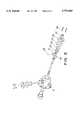
- FIG. 1is a schematic longitudinal cross-sectional view of a burner according to the present invention installed in a radiant tube furnace.
- FIG. 2is an exploded view of the burner housing and gas inlet tube of FIG. 1.
- FIG. 3is an enlarged cross-sectional view of the burner tip assembly of FIG. 1.
- FIG. 4is a cross-sectional view of the burner nozzle of FIG. 3.
- FIG. 5ais a cross-sectional view of the burner tip of FIG. 3.
- FIG. 5bis a radial cross-sectional view of the mixing chamber of FIG. 5a.
- FIG. 6is a schematic cross-sectional diagram of the ignition rod assembly.
- FIG. 7ais a side view of an air shroud.
- FIG. 7bis an end view of the air shroud of FIG. 7a.
- the present inventionis directed to spark ignited burners that can be used in essentially any application where a gaseous fuel is burned.
- the spark ignited burner of the present inventionis particularly useful in gas fired radiant tube furnaces, because of its unique ability to produce a long diffusion-type flame which can be used to uniformly heat a radiant tube.
- the spark ignited burner of the present inventionutilizes a plasma-type ignition system which incorporates a continuous spark that provides a high energy ignition.
- the burnerprovides for a small amount of air-gas pre-mix at the exact point of ignition which ignites a primary gas stream which in turn ignites the main burner raw gas stream.
- the continuous sparkis maintained by applying an electrical potential across the primary air and gas inlet tubes at a narrow annular gap between the outlet ends of the primary air and gas inlet tubes. In operation, the continuous spark established and maintained across the annular gap moves randomly around the annular gap.
- the annular spark gapprovides a large electrode area at which the ignition spark can be established and maintained, thus extending the service life of the burner.
- the ignited main burner raw gas streamflows centrally through a radiant tube, and is surrounded by an annular stream of preheated combustion air, flowing at a matching velocity. This produces a long diffusion-type flame which uniformly heats the radiant tube.
- the annular stream of preheated combustion air which surrounds the ignited main burner raw gas streamis axially directed as it leaves the burner so as to reduce turbulence, and thus produce a long uniform flame which extends throughout the radiant tube.
- the low turbulence-low temperature flametransfers energy with high efficiency while reducing potentially polluting oxides of nitrogen in the exhaust gas stream.
- Carbon monoxide emissionscan be lowered by 20 to 40 percent or more utilizing the burner of the present invention, and fuel consumption can be reduced by 35 to 50 percent.
- FIG. 1is a schematic longitudinal cross-sectional view of a burner according to the present invention installed in a radiant tube furnace.
- the burnerhas a housing assembly which includes burner housing 1 and air inlet housing 2. As shown in FIG. 1, the burner housing 1 and air inlet housing 2 are secured together at respective flanges 3 and 4 by suitable mechanical fasteners 5.
- the air inlet housing 2is likewise provided with a flange 6 or other suitable connector by which it can be attached to a furnace 7 at an opening of a radiant tube 8 in a known manner.
- the radiant tube 8may be U-shaped, M-shaped, or have any other suitable shape.
- the radiant tube 8can be a pressure tube, a negative pressure tube, or an electrified tube.
- the basic elements of the burnerinclude the gas inlet tube 9, the primary air tube 10, and the burner tip assembly 11.
- the gas inlet tube 9 and the primary air tube 10are supported by the burner housing 1 so as to be coaxial and concentric as depicted.
- the primary air tube 10extends outwardly from the front of the burner housing 1 as depicted in FIG. 1.
- Suitable means for attaching primary air tube 10 to the front of burner housing 1may include a collar 12 into which primary air tube 10 can be inserted and a plurality of set screws 13 which can be tightened to secure primary air tube 10 in collar 12.
- Other equivalent mechanical meansmay be used to attach the primary air tube 10 to the front of burner housing 1, such as a threaded collar and cooperating threads on the primary air tube.
- the primary air tube 10is in fluid communication with primary air chamber 14. Air is introduced into air chamber 14 through primary air inlet 15. As shown in FIG. 1, air flow regulating valves, including a shutoff valve can be connected to primary air inlet 15. In FIG. 1, port 16 is provided in burner housing 1 to gain access to primary air chamber 14. Port 16 is plugged during operation of the burner.
- the gas inlet tube 9extends through the burner housing 1 and outwardly beyond the front face of the burner housing 1 coaxially with primary air tube 10.
- the gas inlet tube 9is in fluid communication with a gas inlet 17 to which is connected suitable control valves as discussed in more detail below.
- FIG. 2is an exploded view of the burner housing 1 which depicts one manner by which the gas inlet tube 9 can be attached thereto.
- the rear portion of the burner housing 1includes a stepped through-bore 18.
- Through-bore 18receives a set of ring-shaped insulating elements including first, second and third insulating elements.
- the first insulating element 19has an outer diameter slightly smaller than the inner diameter of the through-bore, and a central hole which is slightly larger than the outer diameter of the gas inlet tube 9. The first insulating element 19 abuts the stepped portion of through-bore 18 as shown in FIG. 1.
- the second insulating element 20has the same outer diameter as the first insulating element 19. However, the central hole in the second insulating element 20 is sized so as to receive a set collar 21 which is slid over gas inlet tube 9 and secured in position at or near the end of the gas inlet tube 9 by one or more set screws 22 (one shown).
- the third insulating element 23is of the same size as the first insulating element 19.
- the gas inlet tube 9is attached to burner housing 1 by fixing set collar 21 at or near the end of the gas inlet tube 9, sandwiching the set collar between the first and third insulating elements 19 and 23 with the second insulating element 20 positioned over set collar 21, and positioning the assembly into through-bore 18.
- gasket 24(FIG. 2) and flange 25 are used to secure the insulator/set collar assembly in through-bore 18.
- Suitable mechanical fastenerssuch as bolts 26 can be used to secure flange 25 in position.
- Bushing 27is received in gas inlet 17 and can be attached to a bore in flange 25 by screw threads.
- the opposite or front ends of the gas inlet and primary inlet tubes 9 and 10are unsupported by the radiant tube 8 into which they are inserted when the burner is attached to furnace 7.
- a burner tip assembly 11is attached to the ends of the gas inlet tube 9 and the primary air tube 10.
- the burner tip assembly 11 shown in FIG. 3includes a burner nozzle 28 which is attached to the front end of the gas inlet tube 9, and a burner tip 29 which is attached to the front end of the primary air tube 10.
- FIG. 4is a cross-sectional view of the burner nozzle 28.
- the burner nozzle 28is made from a high temperature resistant alloy such as stainless steel, and includes a shallow stepped bore 30 by which it can be attached to the gas inlet tube 9.
- the inner and outer diameters of the burner nozzle 28are substantially the same as the inner and outer diameters of the inlet tube 9 except for a restrictive orifice 31 provided at the tip of the burner nozzle 28.
- This restrictive orifice 31is provided to create a back pressure which forces a portion of the fuel gas to flow outward through a plurality of openings 32 provided in the wall of the burner nozzle 28 adjacent restrictive orifice 31.
- FIG. 5ais a cross-sectional view of the burner tip 29.
- the burner tip 29includes a main body portion 33 and a flame retention cup 34 which extends from the front portion of the main body portion 33.
- the main body portion 33 of the burner tip 29includes a multiple stepped bore 35, having first 36, second 37, third 38, and fourth 39 stepped portions of progressively smaller diameters.
- the first stepped portion 36 of bore 35is dimensioned to receive the front end of primary air tube 10 as shown in FIG. 1.
- the second stepped portion 37is dimensioned to receive ceramic spacers 40 (see FIG. 3) which maintain the alignment of the burner assembly 11 and electrically insulate the gas inlet tube 9 from the primary air tube 10 and other elements of the burner tip assembly 11.
- the ceramic spacers 40preferably have a square cross-sectional shape and diagonal dimensions which are slightly smaller that the inner diameter of the second stepped bore portion 37. This ensures that the ceramic spacers 40 do not block the flow of primary air through the annular space 41 between the burner nozzle 28 and the burner tip 29 (FIG. 3).
- the ceramic spacers 40may have other non-circular cross-sectional shapes including triangular, and other polygonal and non-polygonal shapes so long as they do not completely block the flow of primary air through the annular space 41 between the burner nozzle 28 and the burner tip 29.
- Each of the ceramic spacers 40includes a centrally located through-hole having an inner diameter which is slightly larger than the outside diameter of the burner nozzle 28. The burner nozzle 28 is received in these through-holes as depicted in FIGS. 1 and 3.
- the third stepped bore portion 38defines a pre-mixing chamber 42 into which fuel gas passing through openings 32 of the burner nozzle 28 mixes with the primary air flow.
- the third stepped bore portion 28can be defined by fluted or grooved structures which ensure that the ceramic spacers 40 do not significantly block the flow of gases through annular space 41.
- the fluted or grooved structureassists in more efficient mixing of the primary air and fuel gas passing through openings 32.
- the fourth stepped bore portion 39has an inner diameter which is sized to form an annular or ignition spark discharge gap 42 between the distal end of burner nozzle 28 and the front end of burner tip 29. It is across this gap 42 that an ignition spark is generated and maintained when an electric potential is applied to the gas inlet tube 9 and the primary air tube 10 is grounded. In operation, the ignition spark moves randomly around annular gap 42.
- Flame retention cup 35extends from the front end of the burner tip 29 in both radial and longitudinal directions, and includes a plurality of openings 43 adjacent the end of the burner tip 29 through which a portion of the main combustion air stream can enter the flame retention cup 34 and mix with the main gas stream exiting restrictive orifice 31.
- FIG. 6is a schematic cross-sectional diagram of the ignition rod assembly.
- an electrode or ignition rod 43is connected to the gas inlet tube 9. This is done by providing a stepped bore 44 in one side of the burner housing 1. For example, in FIG. 1 the stepped bore 44 would have an axis which would extend out of the page.
- An insulator 45is received in stepped bore 44 and secured therein by a retaining flange 46 which is attached by mechanical fasteners to the burner housing 1.
- the insulator 45includes a through-hole 47 through which the electrode or ignition rod 43 extends.
- the electrode or ignition rod 43is attached to the outer surface of gas inlet tube 9 by a set collar 48 which is secured to the gas inlet tube 9 by one or more set screws (not shown) and/or by providing threads on the end of the electrode or ignition rod 43 and screwing the threaded end thereof into set collar 48.
- electrode or ignition rod 43which extends out through insulator 45 is secured against the insulator 45 by means of mechanical fasteners, such as brass nuts 49 and washer 50.
- An air shroud 51is provided in the air inlet housing 2 in the annular space between the primary air inlet tube 10 and the wall of the air inlet housing 2.
- the air shroud 51 shown in FIGS. 7a and 7bincludes a cylindrical body portion 52 and a plurality of fins or ribs 53 which extend axially along a portion of the outer surface of the cylindrical body portion 52.
- the ratio of the height of the fins or ribs 53 to the diameter of the cylindrical body portion 52is about 0.18 to 0.44.
- the air shroud 51diverts and directs the flow of the main combustion air entering the air inlet housing 2 so that the air, which enters the housing in a radial direction, is evenly distributed about the primary air tube 10 and directed axially along the primary air tube 10 as it exits the air inlet housing 2.
- the air flowexits the air inlet housing in a laminar flow pattern. This ensures that the main gas flame generated in the flame retention cup 34 extends within the surrounding annular air flow along the length of the radiant tube 8, so as to effect complete combustion of the fuel gas and thereby minimize undesirable combustion products.
- the fuel gasenters the burner housing 1 through a gas supply line (not shown) which is connected to metering orifice 54.
- This metering orifice 54is connected to a fitting 55 which includes a sight glass 56 that allows visual and instrumental (e.g. ultra violet) observation of the main burner flame though the central axis of the gas inlet tube 9.
- primary air flowis established by introducing air into primary air chamber 14 via primary air inlet 15.
- Fuel gasis introduced into gas inlet tube 9 through inlet 17.
- an ignition sparkis generated and maintained between the gas inlet tube 9 and the primary air tube 10 across ignition spark discharge gap 42 by applying an electric potential on the order of between 6,000 and 10,000 volts to the igniter rod 43.
- Air and fuel gas which are pre-mixed in the pre-mixing chamber defined by the third stepped bore position 38are ignited as they pass through gap 42 and encounter the ignition spark. This ignited air-fuel gas mixture in turn ignites the main gas flow which enters the flame retention cup 34 from the burner nozzle 28.
- the length of the main gas flameis controlled by adjusting the primary to main combustion air flow ratios. Such adjustment allows the burner assembly to obtain optimum tube temperature over a wide range of firing rates and preheated air temperatures.
- at least the main combustion airis heated by a recuperator which recovers heat from the exhaust end of the radiant tube in a known manner.
- Preheated air temperaturesof up to 650° C. or greater can be used with the burner assembly of the present invention. Stability can be maintained and flame length can be controlled with firing rates of as little as 80,000 BTU/Hr input to as much as 700,000 BTU/Hr.
- the burner assembly of the present inventioncan produce an extremely stable flame and luminous envelope profile that maximizes heat release throughout the radiant tube. This effect reduces thermal stress on the radiant tube which can occur during uneven heating.
- the use of a continuous ignition sparkensures instant ignition of the fuel gas during pulsed fuel gas operation and thus uniform heating of the radiant tube. Because of its ability to provide uniform heating, it has been determined that the burner assembly of the present invention can be used in conjunction with radiant tubes which are made of materials such as ceramics which cannot tolerate thermal stresses.
- the use of a continuous ignition sparkallows the burner assembly to operate from the Duration Adjustment Type (DAT) output from a Proportional, Derivative, Integral (PID) control loop.
- DATDuration Adjustment Type
- PIDProportional, Derivative, Integral
- tube temperature variationsas low as ⁇ 4° F. have been achieved.
- the burner assembly of the present inventioncan be operated with proportional control over the entire firing rate range, in a high-low mode, an on-off mode or a pulse-fired mode, which is preferred because temperature control is optimized.
- the burner assemblyis preferably constructed of cast iron and carbon steel, with the high temperature components being constructed of stainless steel.
- the insulator elementsare made from electrically insulative ceramic materials.
Landscapes
- Engineering & Computer Science (AREA)
- Chemical & Material Sciences (AREA)
- Combustion & Propulsion (AREA)
- Mechanical Engineering (AREA)
- General Engineering & Computer Science (AREA)
- Combustion Of Fluid Fuel (AREA)
Abstract
Description
Claims (39)
Priority Applications (1)
| Application Number | Priority Date | Filing Date | Title |
|---|---|---|---|
| US08/709,387US5779465A (en) | 1996-09-06 | 1996-09-06 | Spark ignited burner |
Applications Claiming Priority (1)
| Application Number | Priority Date | Filing Date | Title |
|---|---|---|---|
| US08/709,387US5779465A (en) | 1996-09-06 | 1996-09-06 | Spark ignited burner |
Publications (1)
| Publication Number | Publication Date |
|---|---|
| US5779465Atrue US5779465A (en) | 1998-07-14 |
Family
ID=24849655
Family Applications (1)
| Application Number | Title | Priority Date | Filing Date |
|---|---|---|---|
| US08/709,387Expired - LifetimeUS5779465A (en) | 1996-09-06 | 1996-09-06 | Spark ignited burner |
Country Status (1)
| Country | Link |
|---|---|
| US (1) | US5779465A (en) |
Cited By (12)
| Publication number | Priority date | Publication date | Assignee | Title |
|---|---|---|---|---|
| WO2006043870A1 (en)* | 2004-10-22 | 2006-04-27 | Sandvik Intellectual Property Ab | Method and device for igniting and monitoring a burner. |
| JP2008261617A (en)* | 2007-03-16 | 2008-10-30 | Chugai Ro Co Ltd | Radiant tube burner |
| US20100183989A1 (en)* | 2009-01-16 | 2010-07-22 | L'air Liquide Societe Anonyme Pour L'etude Et L'exploitation Des Procedes Georges Claude | Air-Gas Pilot Burner that can Operate with Oxygen |
| US20130213005A1 (en)* | 2012-02-08 | 2013-08-22 | Soundblast Technologies, Llc | System and method for zero reaction time combustion |
| WO2013184928A1 (en)* | 2012-06-07 | 2013-12-12 | Chentronics Corporation | Combined high energy igniter and flame detector |
| US20170184311A1 (en)* | 2015-12-28 | 2017-06-29 | Souhel Khanania | Burner Assembly and Heat Exchanger |
| US20170184304A1 (en)* | 2015-12-28 | 2017-06-29 | Souhel Khanania | Burner Assembly and Heat Exchanger |
| US9995481B2 (en) | 2011-12-20 | 2018-06-12 | Eclipse, Inc. | Method and apparatus for a dual mode burner yielding low NOx emission |
| US20180306438A1 (en)* | 2015-12-28 | 2018-10-25 | Souhel Khanania | Burner Assembly And Systems Incorporating A Burner Assembly |
| CN110513719A (en)* | 2019-08-12 | 2019-11-29 | 西安航天动力研究所 | A gas oxygen/gas methane torch igniter |
| KR102076156B1 (en)* | 2018-10-15 | 2020-02-13 | 한국에너지기술연구원 | Regenerative type radiant tube burner with plasma reformer |
| US11690471B2 (en) | 2015-12-28 | 2023-07-04 | Souhel Khanania | Cooking system with burner assembly and heat exchanger |
Citations (19)
| Publication number | Priority date | Publication date | Assignee | Title |
|---|---|---|---|---|
| US1835215A (en)* | 1930-03-22 | 1931-12-08 | Nat Welding Equipment Company | Heating torch |
| US2073448A (en)* | 1933-03-09 | 1937-03-09 | Western Electric Co | Burner |
| US2796118A (en)* | 1954-07-21 | 1957-06-18 | Hanck Mfg Co | Burner for tube firing |
| US2996113A (en)* | 1957-07-10 | 1961-08-15 | Selas Corp Of America | Burner |
| US3007084A (en)* | 1958-12-24 | 1961-10-31 | Harvey A Thomasian | Ignition means |
| US3032096A (en)* | 1953-05-01 | 1962-05-01 | Minor W Stoul | Combustion apparatus |
| US3361185A (en)* | 1966-04-15 | 1968-01-02 | North Western Gas Board | Gas burners |
| US3418060A (en)* | 1967-05-25 | 1968-12-24 | Eclipse Fuel Eng Co | Nozzle mixing gas burner |
| US3439995A (en)* | 1966-09-30 | 1969-04-22 | Crown Sangyo Kk | Spark ignited gas burner |
| US3529915A (en)* | 1967-06-09 | 1970-09-22 | Ishikawajima Harima Heavy Ind | Burner |
| US3685949A (en)* | 1970-12-18 | 1972-08-22 | Derek Vincent Greaves | Aerated gas burners |
| US4431400A (en)* | 1981-08-04 | 1984-02-14 | Union Carbide Corporation | Ignition system for post-mixed burner |
| US4494923A (en)* | 1982-08-25 | 1985-01-22 | L'air Liquide, Societe Anonyme Pour L'etude Et L'exploitation Des Procedes Georges Claude | Oxy-fuel burners |
| US4496314A (en)* | 1983-02-28 | 1985-01-29 | Beresford N Clarke | Recuperator |
| US4524752A (en)* | 1983-04-26 | 1985-06-25 | Clarke Beresford N | Recuperator |
| US4541798A (en)* | 1983-11-07 | 1985-09-17 | Union Carbide Corporation | Post-mixed spark-ignited burner |
| US4595353A (en)* | 1984-05-23 | 1986-06-17 | Shell Oil Company | Burner with ignition device |
| US5000159A (en)* | 1990-03-19 | 1991-03-19 | Mpi Furnace Company | Spark ignited burner |
| US5460515A (en)* | 1991-11-22 | 1995-10-24 | Aichelin Gmbh | Burner for an industrial furnace |
- 1996
- 1996-09-06USUS08/709,387patent/US5779465A/ennot_activeExpired - Lifetime
Patent Citations (19)
| Publication number | Priority date | Publication date | Assignee | Title |
|---|---|---|---|---|
| US1835215A (en)* | 1930-03-22 | 1931-12-08 | Nat Welding Equipment Company | Heating torch |
| US2073448A (en)* | 1933-03-09 | 1937-03-09 | Western Electric Co | Burner |
| US3032096A (en)* | 1953-05-01 | 1962-05-01 | Minor W Stoul | Combustion apparatus |
| US2796118A (en)* | 1954-07-21 | 1957-06-18 | Hanck Mfg Co | Burner for tube firing |
| US2996113A (en)* | 1957-07-10 | 1961-08-15 | Selas Corp Of America | Burner |
| US3007084A (en)* | 1958-12-24 | 1961-10-31 | Harvey A Thomasian | Ignition means |
| US3361185A (en)* | 1966-04-15 | 1968-01-02 | North Western Gas Board | Gas burners |
| US3439995A (en)* | 1966-09-30 | 1969-04-22 | Crown Sangyo Kk | Spark ignited gas burner |
| US3418060A (en)* | 1967-05-25 | 1968-12-24 | Eclipse Fuel Eng Co | Nozzle mixing gas burner |
| US3529915A (en)* | 1967-06-09 | 1970-09-22 | Ishikawajima Harima Heavy Ind | Burner |
| US3685949A (en)* | 1970-12-18 | 1972-08-22 | Derek Vincent Greaves | Aerated gas burners |
| US4431400A (en)* | 1981-08-04 | 1984-02-14 | Union Carbide Corporation | Ignition system for post-mixed burner |
| US4494923A (en)* | 1982-08-25 | 1985-01-22 | L'air Liquide, Societe Anonyme Pour L'etude Et L'exploitation Des Procedes Georges Claude | Oxy-fuel burners |
| US4496314A (en)* | 1983-02-28 | 1985-01-29 | Beresford N Clarke | Recuperator |
| US4524752A (en)* | 1983-04-26 | 1985-06-25 | Clarke Beresford N | Recuperator |
| US4541798A (en)* | 1983-11-07 | 1985-09-17 | Union Carbide Corporation | Post-mixed spark-ignited burner |
| US4595353A (en)* | 1984-05-23 | 1986-06-17 | Shell Oil Company | Burner with ignition device |
| US5000159A (en)* | 1990-03-19 | 1991-03-19 | Mpi Furnace Company | Spark ignited burner |
| US5460515A (en)* | 1991-11-22 | 1995-10-24 | Aichelin Gmbh | Burner for an industrial furnace |
Cited By (27)
| Publication number | Priority date | Publication date | Assignee | Title |
|---|---|---|---|---|
| EP1802917A4 (en)* | 2004-10-22 | 2015-08-19 | Sandvik Intellectual Property | Method and device for igniting and monitoring a burner. |
| US20070298359A1 (en)* | 2004-10-22 | 2007-12-27 | Bo Jonsson | Method and Device for Igniting and Monitoring a Burner |
| KR100885715B1 (en) | 2004-10-22 | 2009-02-26 | 산드빅 인터렉츄얼 프로퍼티 에이비 | Burner ignition and monitoring method and device |
| US7833011B2 (en) | 2004-10-22 | 2010-11-16 | Sandvik Intellectual Property Ab | Method and device for igniting and monitoring a burner |
| WO2006043870A1 (en)* | 2004-10-22 | 2006-04-27 | Sandvik Intellectual Property Ab | Method and device for igniting and monitoring a burner. |
| JP2008261617A (en)* | 2007-03-16 | 2008-10-30 | Chugai Ro Co Ltd | Radiant tube burner |
| US20100183989A1 (en)* | 2009-01-16 | 2010-07-22 | L'air Liquide Societe Anonyme Pour L'etude Et L'exploitation Des Procedes Georges Claude | Air-Gas Pilot Burner that can Operate with Oxygen |
| US9995481B2 (en) | 2011-12-20 | 2018-06-12 | Eclipse, Inc. | Method and apparatus for a dual mode burner yielding low NOx emission |
| US20130213005A1 (en)* | 2012-02-08 | 2013-08-22 | Soundblast Technologies, Llc | System and method for zero reaction time combustion |
| US9546788B2 (en) | 2012-06-07 | 2017-01-17 | Chentronics, Llc | Combined high energy igniter and flame detector |
| US9822978B2 (en) | 2012-06-07 | 2017-11-21 | Chentronics, Llc | Combined high energy igniter and flame detector |
| CN104822991A (en)* | 2012-06-07 | 2015-08-05 | 申特罗尼克斯有限责任公司 | Combined high energy igniter and flame detector |
| KR20150068349A (en)* | 2012-06-07 | 2015-06-19 | 첸트로닉스, 엘엘씨 | Combined high energy igniter and flame detector |
| JP2015522788A (en)* | 2012-06-07 | 2015-08-06 | チェントロニクス コーポレーション | Combined high energy igniter and flame detector |
| WO2013184928A1 (en)* | 2012-06-07 | 2013-12-12 | Chentronics Corporation | Combined high energy igniter and flame detector |
| CN104822991B (en)* | 2012-06-07 | 2017-08-25 | 申特罗尼克斯有限责任公司 | Combined type energetic igniter and flame detector |
| US20180306438A1 (en)* | 2015-12-28 | 2018-10-25 | Souhel Khanania | Burner Assembly And Systems Incorporating A Burner Assembly |
| US20170184304A1 (en)* | 2015-12-28 | 2017-06-29 | Souhel Khanania | Burner Assembly and Heat Exchanger |
| US20170184311A1 (en)* | 2015-12-28 | 2017-06-29 | Souhel Khanania | Burner Assembly and Heat Exchanger |
| US11346549B2 (en)* | 2015-12-28 | 2022-05-31 | Souhel Khanania | Burner assembly and systems incorporating a burner assembly |
| US11346548B2 (en)* | 2015-12-28 | 2022-05-31 | Souhel Khanania | Burner assembly and heat exchanger |
| AU2016380160B2 (en)* | 2015-12-28 | 2022-07-14 | Souhel Khanania | Burner assembly and heat exchanger |
| US11690471B2 (en) | 2015-12-28 | 2023-07-04 | Souhel Khanania | Cooking system with burner assembly and heat exchanger |
| US12222102B2 (en) | 2015-12-28 | 2025-02-11 | Souhel Khanania | Burner assembly and systems incorporating a burner assembly |
| KR102076156B1 (en)* | 2018-10-15 | 2020-02-13 | 한국에너지기술연구원 | Regenerative type radiant tube burner with plasma reformer |
| CN110513719A (en)* | 2019-08-12 | 2019-11-29 | 西安航天动力研究所 | A gas oxygen/gas methane torch igniter |
| CN110513719B (en)* | 2019-08-12 | 2021-01-12 | 西安航天动力研究所 | Oxygen/methane torch igniter |
Similar Documents
| Publication | Publication Date | Title |
|---|---|---|
| US5431559A (en) | Oxygen-fuel burner with staged oxygen supply | |
| US5490775A (en) | Forward injection oxy-fuel burner | |
| US4825658A (en) | Fuel nozzle with catalytic glow plug | |
| US5779465A (en) | Spark ignited burner | |
| US20030235798A1 (en) | U-tube diffusion flame burner assembly having unique flame stabilization | |
| CZ49293A3 (en) | Combustion system employing oxygen and fuel | |
| KR101838761B1 (en) | Non-centric oxy-fuel burner for glass melting systems | |
| EP0733187B1 (en) | Oxygen-fuel burner with integral staged oxygen supply | |
| US4780077A (en) | Flame retention head assembly for fuel burners | |
| US4120639A (en) | High momentum burners | |
| CA2079136C (en) | Radiant gas burner | |
| EP0119786B1 (en) | Improvements in burners | |
| CA1100029A (en) | Premix gas burner assembly for copper melting furnace | |
| JP2001524656A (en) | Oxy-fuel pilot with integrated ignition | |
| HUP0003643A2 (en) | Burning | |
| CA1263059A (en) | Annular nozzle burner and method of operation | |
| US5000159A (en) | Spark ignited burner | |
| GB2279141A (en) | Burner assembly for a radiant heater | |
| US3247884A (en) | Burner means for furnaces | |
| US4470798A (en) | Method of operating a burner without using a fuel pump, and burner assembly operating in accordance with such method | |
| CN204084368U (en) | Low-heat value gas radiant tube burner | |
| USRE39425E1 (en) | Oxygen-fuel burner with integral staged oxygen supply | |
| CN113028398B (en) | Glow flame generating method of glow flame burner and glow flame burner | |
| RU2042883C1 (en) | Burner | |
| RU2230257C2 (en) | Device for burning gaseous fuel |
Legal Events
| Date | Code | Title | Description |
|---|---|---|---|
| STCF | Information on status: patent grant | Free format text:PATENTED CASE | |
| FEPP | Fee payment procedure | Free format text:PAYOR NUMBER ASSIGNED (ORIGINAL EVENT CODE: ASPN); ENTITY STATUS OF PATENT OWNER: LARGE ENTITY | |
| FPAY | Fee payment | Year of fee payment:4 | |
| AS | Assignment | Owner name:MAXON CORPORATION, INDIANA Free format text:ASSIGNMENT OF ASSIGNORS INTEREST;ASSIGNORS:CLARKE, BERESFORD N.;CLARKE, JOHN B.;REEL/FRAME:012590/0697;SIGNING DATES FROM 20010926 TO 20011012 | |
| REMI | Maintenance fee reminder mailed | ||
| AS | Assignment | Owner name:MASSACHUSETTS MUTUAL LIFE INSURANCE COMPANY C/O BA Free format text:SECURITY AND PLEDGE AGREEMENT;ASSIGNOR:MAXON CORPORATION;REEL/FRAME:015223/0591 Effective date:20040930 Owner name:C.M. LIFE INDSURANCE COMPANY C/O MASSACHUSETTS MUT Free format text:SECURITY AND PLEDGE AGREEMENT;ASSIGNOR:MAXON CORPORATION;REEL/FRAME:015223/0591 Effective date:20040930 Owner name:MASSMUTUAL CORPORATE INVESTOR C/O BABSON CAPITAL M Free format text:SECURITY AND PLEDGE AGREEMENT;ASSIGNOR:MAXON CORPORATION;REEL/FRAME:015223/0591 Effective date:20040930 Owner name:MASSMUTUAL PARTICIPATION INVESTORS C/O BABSON CAPI Free format text:SECURITY AND PLEDGE AGREEMENT;ASSIGNOR:MAXON CORPORATION;REEL/FRAME:015223/0591 Effective date:20040930 Owner name:JOHN HANCOCK LIFE INSURACE COMPANY, MASSACHUSETTS Free format text:SECURITY AND PLEDGE AGREEMENT;ASSIGNOR:MAXON CORPORATION;REEL/FRAME:015223/0591 Effective date:20040930 Owner name:HANCOCK MEZZANINE PARTNERS III L.P. C/O JOHN HANCO Free format text:SECURITY AND PLEDGE AGREEMENT;ASSIGNOR:MAXON CORPORATION;REEL/FRAME:015223/0591 Effective date:20040930 Owner name:ALLSTATE LIFE INSURANCE COMPANY C/O JOHN HANCOCK L Free format text:SECURITY AND PLEDGE AGREEMENT;ASSIGNOR:MAXON CORPORATION;REEL/FRAME:015223/0591 Effective date:20040930 Owner name:SIGNATURE 7 L.P. C/O JOHN HANCOCK LIFE INSURANCE C Free format text:SECURITY AND PLEDGE AGREEMENT;ASSIGNOR:MAXON CORPORATION;REEL/FRAME:015223/0591 Effective date:20040930 Owner name:SIGNATURE 5 L.P. C/O JOHN HANCOCK LIFE INSURANCE C Free format text:SECURITY AND PLEDGE AGREEMENT;ASSIGNOR:MAXON CORPORATION;REEL/FRAME:015223/0591 Effective date:20040930 | |
| FPAY | Fee payment | Year of fee payment:8 | |
| AS | Assignment | Owner name:MAXON CORPORATION, INDIANA Free format text:RELEASE BY SECURED PARTY;ASSIGNORS:C.M. LIFE INSURANCE COMPANY;MASSMUTUAL PARTICIPATION INVESTORS;MASSMUTUAL CORPORATE INVESTORS;AND OTHERS;REEL/FRAME:020218/0033 Effective date:20071207 Owner name:MAXON CORPORATION, INDIANA Free format text:RELEASE BY SECURED PARTY;ASSIGNORS:JOHN HANCOCK LIFE INSURANCE COMPANY;HANCOCK MEZZANINE PARTNERS III, L.P.;SIGNATURE 5 L.P.;AND OTHERS;REEL/FRAME:020218/0047 Effective date:20071207 | |
| FEPP | Fee payment procedure | Free format text:PAYER NUMBER DE-ASSIGNED (ORIGINAL EVENT CODE: RMPN); ENTITY STATUS OF PATENT OWNER: LARGE ENTITY Free format text:PAYOR NUMBER ASSIGNED (ORIGINAL EVENT CODE: ASPN); ENTITY STATUS OF PATENT OWNER: LARGE ENTITY | |
| FEPP | Fee payment procedure | Free format text:PAT HOLDER NO LONGER CLAIMS SMALL ENTITY STATUS, ENTITY STATUS SET TO UNDISCOUNTED (ORIGINAL EVENT CODE: STOL); ENTITY STATUS OF PATENT OWNER: LARGE ENTITY | |
| REFU | Refund | Free format text:REFUND - PAYMENT OF MAINTENANCE FEE, 12TH YR, SMALL ENTITY (ORIGINAL EVENT CODE: R2553); ENTITY STATUS OF PATENT OWNER: LARGE ENTITY | |
| FPAY | Fee payment | Year of fee payment:12 | |
| SULP | Surcharge for late payment | Year of fee payment:11 |