US5778813A - Composite steel structural plastic sandwich plate systems - Google Patents
Composite steel structural plastic sandwich plate systemsDownload PDFInfo
- Publication number
- US5778813A US5778813AUS08/746,539US74653996AUS5778813AUS 5778813 AUS5778813 AUS 5778813AUS 74653996 AUS74653996 AUS 74653996AUS 5778813 AUS5778813 AUS 5778813A
- Authority
- US
- United States
- Prior art keywords
- metal layer
- hull
- containment vessel
- laminate
- outer metal
- Prior art date
- Legal status (The legal status is an assumption and is not a legal conclusion. Google has not performed a legal analysis and makes no representation as to the accuracy of the status listed.)
- Expired - Lifetime
Links
Images


Classifications
- B—PERFORMING OPERATIONS; TRANSPORTING
- B32—LAYERED PRODUCTS
- B32B—LAYERED PRODUCTS, i.e. PRODUCTS BUILT-UP OF STRATA OF FLAT OR NON-FLAT, e.g. CELLULAR OR HONEYCOMB, FORM
- B32B3/00—Layered products comprising a layer with external or internal discontinuities or unevennesses, or a layer of non-planar shape; Layered products comprising a layer having particular features of form
- B32B3/10—Layered products comprising a layer with external or internal discontinuities or unevennesses, or a layer of non-planar shape; Layered products comprising a layer having particular features of form characterised by a discontinuous layer, i.e. formed of separate pieces of material
- B—PERFORMING OPERATIONS; TRANSPORTING
- B32—LAYERED PRODUCTS
- B32B—LAYERED PRODUCTS, i.e. PRODUCTS BUILT-UP OF STRATA OF FLAT OR NON-FLAT, e.g. CELLULAR OR HONEYCOMB, FORM
- B32B1/00—Layered products having a non-planar shape
- B—PERFORMING OPERATIONS; TRANSPORTING
- B32—LAYERED PRODUCTS
- B32B—LAYERED PRODUCTS, i.e. PRODUCTS BUILT-UP OF STRATA OF FLAT OR NON-FLAT, e.g. CELLULAR OR HONEYCOMB, FORM
- B32B15/00—Layered products comprising a layer of metal
- B32B15/04—Layered products comprising a layer of metal comprising metal as the main or only constituent of a layer, which is next to another layer of the same or of a different material
- B32B15/06—Layered products comprising a layer of metal comprising metal as the main or only constituent of a layer, which is next to another layer of the same or of a different material of natural rubber or synthetic rubber
- B—PERFORMING OPERATIONS; TRANSPORTING
- B32—LAYERED PRODUCTS
- B32B—LAYERED PRODUCTS, i.e. PRODUCTS BUILT-UP OF STRATA OF FLAT OR NON-FLAT, e.g. CELLULAR OR HONEYCOMB, FORM
- B32B15/00—Layered products comprising a layer of metal
- B32B15/04—Layered products comprising a layer of metal comprising metal as the main or only constituent of a layer, which is next to another layer of the same or of a different material
- B32B15/08—Layered products comprising a layer of metal comprising metal as the main or only constituent of a layer, which is next to another layer of the same or of a different material of synthetic resin
- B32B15/095—Layered products comprising a layer of metal comprising metal as the main or only constituent of a layer, which is next to another layer of the same or of a different material of synthetic resin comprising polyurethanes
- B—PERFORMING OPERATIONS; TRANSPORTING
- B32—LAYERED PRODUCTS
- B32B—LAYERED PRODUCTS, i.e. PRODUCTS BUILT-UP OF STRATA OF FLAT OR NON-FLAT, e.g. CELLULAR OR HONEYCOMB, FORM
- B32B15/00—Layered products comprising a layer of metal
- B32B15/18—Layered products comprising a layer of metal comprising iron or steel
- B—PERFORMING OPERATIONS; TRANSPORTING
- B63—SHIPS OR OTHER WATERBORNE VESSELS; RELATED EQUIPMENT
- B63B—SHIPS OR OTHER WATERBORNE VESSELS; EQUIPMENT FOR SHIPPING
- B63B25/00—Load-accommodating arrangements, e.g. stowing, trimming; Vessels characterised thereby
- B63B25/02—Load-accommodating arrangements, e.g. stowing, trimming; Vessels characterised thereby for bulk goods
- B63B25/08—Load-accommodating arrangements, e.g. stowing, trimming; Vessels characterised thereby for bulk goods fluid
- B63B25/082—Arrangements for minimizing pollution by accidents
- B—PERFORMING OPERATIONS; TRANSPORTING
- B63—SHIPS OR OTHER WATERBORNE VESSELS; RELATED EQUIPMENT
- B63B—SHIPS OR OTHER WATERBORNE VESSELS; EQUIPMENT FOR SHIPPING
- B63B3/00—Hulls characterised by their structure or component parts
- B63B3/14—Hull parts
- B—PERFORMING OPERATIONS; TRANSPORTING
- B63—SHIPS OR OTHER WATERBORNE VESSELS; RELATED EQUIPMENT
- B63B—SHIPS OR OTHER WATERBORNE VESSELS; EQUIPMENT FOR SHIPPING
- B63B3/00—Hulls characterised by their structure or component parts
- B63B3/14—Hull parts
- B63B3/16—Shells
- B63B3/20—Shells of double type
- B—PERFORMING OPERATIONS; TRANSPORTING
- B63—SHIPS OR OTHER WATERBORNE VESSELS; RELATED EQUIPMENT
- B63B—SHIPS OR OTHER WATERBORNE VESSELS; EQUIPMENT FOR SHIPPING
- B63B3/00—Hulls characterised by their structure or component parts
- B63B3/14—Hull parts
- B63B3/68—Panellings; Linings, e.g. for insulating purposes
- B—PERFORMING OPERATIONS; TRANSPORTING
- B63—SHIPS OR OTHER WATERBORNE VESSELS; RELATED EQUIPMENT
- B63B—SHIPS OR OTHER WATERBORNE VESSELS; EQUIPMENT FOR SHIPPING
- B63B5/00—Hulls characterised by their construction of non-metallic material
- B—PERFORMING OPERATIONS; TRANSPORTING
- B32—LAYERED PRODUCTS
- B32B—LAYERED PRODUCTS, i.e. PRODUCTS BUILT-UP OF STRATA OF FLAT OR NON-FLAT, e.g. CELLULAR OR HONEYCOMB, FORM
- B32B2311/00—Metals, their alloys or their compounds
- B32B2311/30—Iron, e.g. steel
- B—PERFORMING OPERATIONS; TRANSPORTING
- B32—LAYERED PRODUCTS
- B32B—LAYERED PRODUCTS, i.e. PRODUCTS BUILT-UP OF STRATA OF FLAT OR NON-FLAT, e.g. CELLULAR OR HONEYCOMB, FORM
- B32B2375/00—Polyureas; Polyurethanes
- B—PERFORMING OPERATIONS; TRANSPORTING
- B63—SHIPS OR OTHER WATERBORNE VESSELS; RELATED EQUIPMENT
- B63B—SHIPS OR OTHER WATERBORNE VESSELS; EQUIPMENT FOR SHIPPING
- B63B2231/00—Material used for some parts or elements, or for particular purposes
- B63B2231/02—Metallic materials
- B63B2231/04—Irons, steels or ferrous alloys
- B—PERFORMING OPERATIONS; TRANSPORTING
- B63—SHIPS OR OTHER WATERBORNE VESSELS; RELATED EQUIPMENT
- B63B—SHIPS OR OTHER WATERBORNE VESSELS; EQUIPMENT FOR SHIPPING
- B63B2231/00—Material used for some parts or elements, or for particular purposes
- B63B2231/40—Synthetic materials
- B63B2231/42—Elastomeric materials
Definitions
- the present inventionrelates to a flexible impact and tear resistant composite sandwich plate and construction system for vessels such as tankers, bulk carriers or ships for which it is desirable to contain the vessel contents during conditions of extreme or accidental load.
- a conventional double hullhas longitudinal and transverse frames between the inner and outer hulls.
- a more advanced, alternative double hullhas only longitudinal frames between the inner and outer hulls, allowing for simplified construction suitable for assembly line production by robotic devices.
- Both conventional and advanced double hull designshave transverse bulkheads between cargo compartments in the inner hull, and may have bulkheads between ballast compartments which are generally located between the inner and outer hulls.
- Variations in double hull designinclude constructions with a double bottom only, or with a double bottom and double hull sides. To reduce weight, the deck is generally a single plate construction.
- convexly curved hull plates between longitudinal framesmay provide high energy absorption in the curved plate double hull.
- FIG. 1shows a cross-section of a typical double hull oil tanker designed according to conventional naval architecture.
- FIG. 2illustrates the arrangement of cargo tanks and other sections for a typical double hull vessel.
- double hull construction over conventional single hull designsare also well known. These advantages include improved cargo handling efficiency, better cargo purity, and reduced water pollution by isolating ballast tanks from cargo holds. Furthermore, double hulls constructed to international standards which require a two meter space between inner and outer hulls also offer reduced risk of leakage or rupture due to penetration of the outer hull during collisions or groundings.
- the claimed innovative features of advanced double hullsare improved strength, ease of manufacture and reduced welding and steel surface areas in ballast tanks, increased accessibility to ballast tanks which results in better inspection and improved maintenance and inner hull retention of oil during high energy grounding. With current technology, double hull vessels involved in low energy, low velocity impacts are less likely to be compromised and less likely to cause pollution than a single hull vessel.
- the improved tanker designssuch as double-bottom, double sides, double hull, mid-deck, etc. are known to reduce but not eliminate the risk of oil spills in accidents.
- testsindicate that an advanced all steel double hull design will dissipate more energy than a conventional all steel double hull design, both designs are subject to compromise of the inner hull due to crack propagation resulting from fatigue cracks or from cracks that propagate from a ruptured plate during extreme load events.
- Patents related to improving the energy absorption capacity of double hull construction due to accidental or extreme load events such as grounding or collisioninclude U.S. Pat. Nos. 5,218,919 to Krulikowski III et al. and 5,477,797 to Stuart. Both patents are directed to retrofitting existing single hull tankers with external hulls to make a double hull tanker.
- Krulikowski III et al.describe the use of energy absorbing telescoping members arranged in a truss-like formation to support a laminated steel auxiliary hull to the outside of an existing oil tanker hull. Construction details of attachments to transverse bulkheads and deflection control devices are also described.
- the void between hullsis filled with polyurethane foam/balls to distribute impact forces, to support the auxiliary hull under hydrostatic loads and to provide additional buoyancy in the case where the auxiliary hull is ruptured.
- Stuartdescribes the construction of an auxiliary hull attached to the outside hull of an existing oil tanker. It is composed of a series of longitudinally framed steel plates that form a honeycomb configuration, when viewed in section, between the hulls.
- the combination of stress relief joints, which make the outer hull discontinuous, and the honeycomb inner hull structurecreate a damage resistant hull.
- the constructionalso allows the inner hull space to be flooded to any level to provide the appropriate ballast by means of a pressurized inert gas and a vacuum pressure system.
- U.S. Pat. Nos. 4,083,318 to Verolme and 4,672,906 to Asaiare directed to LNG (liquid natural gas) tankers and to tankers carrying cryogenic or high temperature freight in which the cargo tanks are separate structures from the tanker and do not form part of the load carrying hull girder system of the tanker.
- Hulls constructed according to traditional naval architecture standardsgenerally provide a complex system of steel plates and plate steel structural members, such as frames, bulkheads and girders.
- the carrying capacity of the steel plates and supporting membersis increased by reinforcing the plates and structural members with multiple stiffeners of the type well known in the art, such as flat, angle or channel metal stock fastened to plate surfaces.
- This complex hull structure and plate stiffener systemis a source of fatigue failures and a source for tearing (rupture) of the hull plate during accidental or extreme loads.
- This type of hullis costly to fabricate due to the large number of pieces which must be cut, handled and welded, and because of the significantly increased surface area on which protective coatings must be applied.
- these typical complex structural systemsare very congested, leading to poor access, poor inspection, poor and costly maintenance, and a decreased service life due to corrosion.
- a large scale composite steel polyurethane foam sandwich platehas been tested for its ability to prevent leak and rupture of a hull. These tests illustrate that polyurethane foam does not adequately adhere to the steel plates and has little shear strength. Low shear strength minimizes the flexural capacity of the composite and lack of adhesion precludes the possibility of using polyurethane foam and steel in a composite to increase the in-plane buckling capacity so that plate stiffeners can be eliminated.
- the low density foam used in the test compositehad little or no tensile strength and insufficient compressive strength to be beneficial structurally. Generally, the tested foam acted as a crack arrest layer but did not function structurally. Therefore, the desired crack arresting structural composite configuration was not achieved.
- the tested foampossessed some energy absorption capacity; however, this capacity was small when compared to that of the steel in membrane action.
- the foamlessens the localized straining of the steel plates around a concentrated load point which delays, but does not prevent, the shear tension failure of the steel hull plates.
- the above-described drawbacks inherent in the art for providing double hull tankersare advantageously eliminated in accordance with the teachings of the present invention by bonding a tough structural elastomer between steel plates to form steel-elastomer-steel composite hull panels, frames and supporting members.
- the elastomeris preferably hydrophobic to prevent water absorption which could lead to rusting of the plates and should have sufficient ductility to exceed the yield strain of the steel plates without rupturing.
- the composite panelsare used in constructing at least the inner hull of the double hull.
- the steel-elastomer-steel composite panelsare used to construct the inner hull, outer hull, bulkheads, floors, decks and collapsible frame and support members and may be formed in any necessary shape.
- the elastomer layer within the composite panels forming the inner hullparticularly provides an effective crack arrest layer between the inner steel plate of the inner hull and the outer steel plate of the inner hull, which effectively isolates the inner steel plate of the inner hull from cracks that propagate from the outer hull, the transverse members, such as floor frames and bulkheads, and other supporting elements, such as web frames and horizontal frames, that are designed for both in-service loads and for accidental or extreme loads.
- the composite panelsare stronger and stiffer than conventional steel plates, the number of framing and supporting elements can be significantly reduced while meeting or exceeding current design standards for strength, service life, construction cost, maintenance cost and survivability.
- a composite steel polyurethane elastomer sandwich plate system with properly detailed floor and transverse bulkheads and which is particularly suited for use in containment vessels such as, for example, oil tankers,is fabricated to substantially eliminate the drawbacks associated with known all steel vessels.
- containment vesselssuch as, for example, oil tankers.
- the specific details relating to ship designmay be found in American Bureau of Shipping and affiliated Companies, 1996 Part 3, Hull Construction and Equipment; Part 5, Specialized Vessels and Services, which is incorporated herein by reference.
- FIG. 1is a perspective cross-sectional view of a prior art all-steel double hull oil tanker which includes a unidirectional girder system and stiffened steel hull plates;
- FIG. 2is a plan view of a prior art double hull tanker illustrating the general arrangement of cargo and ballast compartments;
- FIG. 3is a cross-sectional view of a prior art double hull tanker midsection taken at a transverse bulkhead illustrating the structural members and stiffener system;
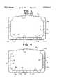
- FIG. 4is a cross-sectional view of a double hull midsection taken at a transverse bulkhead constructed with composite panels according to the present invention
- FIG. 5is a partial cross-section view of a cargo hold of a double hull vessel constructed with composite panels according to the present invention
- FIG. 6is a cutaway cross-section view of a double hull vessel transverse bulkhead construction with composite panels according to the present invention.
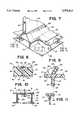
- FIG. 7is a cutaway cross section view of a crack arrest detail for a transverse bulkhead according to the present invention.
- FIG. 8is a cross-section view of a composite panel constructed according to the present invention.
- FIG. 9is a cross-section view of the inner hull and bulkhead constructed with composite panels according to the present invention.
- FIG. 10is a cross-section view of the inner and outer hull and supporting members constructed with composite panels according to the present invention.
- FIG. 11is a cross-section view taken along line 11--11 in FIG. 10, showing details of the elastomer plug sealing the crack arrest cut-out;
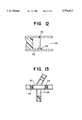
- FIG. 12is a cross-section view of a composite panel under construction according to the present invention.
- FIG. 13is a cross-section view of the inner hull, bulkhead and composite spacer constructed with composite panels according to the present invention.
- teachings of the present inventionare applicable to any structure, vessel, tanker, bulk carrier or ship in which it is desired to contain the contents during an extreme or accidental load event.
- the present inventionwill be discussed in the context of double hull oil tankers.
- teachings of the present inventioncan be incorporated into the structural configuration of other vessels, bulk carriers, etc., such as, road vehicles, rail cars and storage tanks.
- a typical conventional double hull (CDH) design as illustrated in FIGS. 2 and 3, for example, for a 40,000 DWT (deadweight tons) tankeris characterized by an inner hull 10 and an outer hull 12, with an orthogonally stiffened bottom 1, transverse web frames 2 and longitudinal girders 3.
- Hull plates 4are welded or otherwise attached to the longitudinal girders 3.
- Web frames 2, oriented transversely to the longitudinal girders 3,are attached between longitudinal girders 3 to retain and stabilize the girders 3.
- FIG. 2illustrates a typical layout for a tanker having an outer hull 12 and an inner hull 10 in the cargo containing portion of outer hull 12.
- the compartmentalized cargo holds 13 in the inner hull 10are separated by bulkheads 6.
- Compartments 102, outboard from the cargo holds 13,may serve as ballast tanks in the lower part of the hull.
- the advanced double hullhas significantly fewer transverse members, but the advanced double hull does have transverse bulkheads 6 between cargo compartments 13, and may have transverse floor frames 11 between ballast compartments 102 located between the inner and outer hulls.
- the carrying capacity of advanced double hull steel plate componentsis enhanced by fixing numerous stiffeners 7 to the surface of the plate steel components.
- a portion of the inner hull 10is pushed inward ("lifted") either by direct contact with the intruding object, or indirectly by support members, such as, for example, a hull girder 3, or floor frame 11 which is pushed inward by the intruding object.
- the inner hull plates 14 in the impact areamay deform as a membrane until a transverse member 11 restrains the inner hull 10 from further inward movement, e.g., "lift” of the inner hull plate 14 is restrained, causing extreme membrane stresses at or near the location of the intruding object.
- the extreme membrane stresstriggers an initial crack, either in the transverse member 2, 6, 11 restraining the inner hull plate 14, or directly in the restrained inner hull plate 14, leading to inner hull 10 rupture. It is generally required that a spill proof tanker bottom structure must be designed to allow "lift” and inelastic membrane deformation of the inner hull 10 without rupture.
- a crack arrest layer 15(FIG. 4) is incorporated in the hull structure at least at or near all transverse members, such as for example floor frames 24 and bulkheads 26, but preferably throughout the entire hull structure, wherever practical.
- innerwhen “inner” is used with respect to components, it will generally refer to components relatively closer to the cargo hold of the vessel. When “inner” is used with respect to a surface, it will generally refer to a surface facing the cargo hold. In particular, the inner surface 63 (FIG. 8) of the inner metal plate or layer 34 of the inner hull 20 faces and is generally exposed to the cargo hold 68. When “outer” is used with respect to components, it will generally refer to components relatively further from the cargo hold. When “outer” is used with respect to a surface, it will generally refer to a surface facing away from the cargo hold.
- a composite panel vessel construction system for buildingfor example, a tanker constructed with a unidirectional double hull sandwich plate system (UDHSPS), incorporates a tough impact resistant hull 16 composed of steel-elastomer-steel composite panels 18 supported by a properly detailed collapsible structure, some or all of which may also be of composite panel construction.
- the composite panels 18are comprised of an inner metal plate 34 spaced apart from and facing an outer metal plate 36, the inner and outer metal plates being bonded to an intermediate elastomer core 38.
- a deck 40extends from the top of side 74 to the top of side 78 to close the top of the cargo hold 68.
- a bulkhead 26 at each end of the cargo hold 68is connected to the sides 74 and 78, and the bottom 76 and deck 40, to substantially completely enclose cargo hold 68.
- An outer hull 28having two sides 80 and 82 and a bottom 84, is spaced apart from and encloses, respectively, the two sides 74 and 78 and bottom 76 of inner hull 20.
- the outer hull 28is connected to the inner hull 20 by support members including longitudinal girders 22 and transverse floor frames 24. At least the inner hull 20 is constructed of composite panels 18.
- the inner hull 20, outer hull 28, longitudinal girders 22, floor frames 24 and bulkheads 26are constructed of composite panels 18.
- the various components, whether made of composite panels 18 or of conventional single plate steelare connected together by welding or by other conventional means, with certain allowances, discussed below, necessary to accommodate the elastomer core 38 of the composite panel 18.
- the UDHSPSwill significantly enhance survivability of the inner cargo containing hull 20 in the event of a collision or grounding, and significantly reduces, if not eliminates, the outflow of oil during such an event, particularly in comparison to conventional double hull counterparts.
- the UDHSPSis constructed to behave in a ductile mode under accidental or extreme loads and to absorb the energy through inelastic membrane action of the composite panel hull and plastic deformation of conventional steel and/or steel-elastomer-steel composite panel supporting elements. To minimize or eliminate oil outflow, cargo hold crack or tear propagation is prevented.
- the UDHSPScan be designed to provide equivalent or greater strength for operational loads than existing conventional or advanced all-steel double hull vessels designed according to current standards.
- the steel-elastomer-steel hull girder 22according to the present invention has an inner metal plate 34 and an outer metal plate 36 on an elastomer core 38 to provide sufficient bending, shear and torsional strength to act as a hollow thin-walled box beam capable of withstanding typical or extreme static and dynamic loads such as those associated with operating a cargo vessel.
- loadsinclude for example, still water loads, dry docking loads, thermal loads, wave-induced dynamic pressure distributions on the hull, sloshing of liquid cargoes, green-seas on the deck, wave slap, inertia loads, launching and berthing loads, ice breaking loads, slamming, forced vibration, collision and grounding.
- FIGS. 4 and 6illustrate a double hull midship section 42 and transverse bulkhead 26 for a double hull tanker constructed with composite steel-elastomer-steel panels 18.
- Both the inner and outer hulls 20 and 28, respectively,are constructed from composite steel-elastomer-steel panels 18 suitably designed and dimensioned for a vessel of a particular size and purpose.
- the transverse bulkheads 26 shown in FIGS. 6, 7 and 9are also constructed of composite steel-elastomer-steel panels 18 supported by both horizontal and vertical web plates 30 and 32 respectively, which may also be of composite panel 18 construction.
- the composite panels 18can be manufactured as individual components, such as, for example, hull panels 17, floor frames 24, girders 22, bulkheads 26, etc., which can subsequently be shipped or assembled into sub-assemblies of a complete vessel, in a number of different ways.
- the inner and outer metal plates 34 and 36 (FIG. 5) of a composite panel 18are positioned in an appropriate spaced apart relationship to form a cavity 56 (FIG. 12) for the elastomer core 38.
- the inner and outer metal plates 34 and 36 respectivelyare steel.
- Other suitable metalsmay be used, such as for example, stainless steel for high corrosion applications, or aluminum for light weight applications. Because the composite panels 18 are significantly stronger than single plate metal, other softer types of metal may be used to construct composite panels.
- spacer elements 44provided between the inner and outer metal layers 34 and 36.
- the spacer element 44may comprise a continuous strip-like member, or alternatively the spacer element 44 can comprise multiple individual spacer members arranged randomly or in a pattern.
- the spacers 44can be made of metal or any other suitable material that is placed between the metal inner and outer layers 34 and 36.
- the spacer elements 44may be welded or bonded to the inner and/or outer metal layer 34 and 36.
- the spacers 44are continuous strip-like members having opposite longitudinal edges 46 and 50.
- the spacers 44are welded on one longitudinal edge 46 with fillet welds 48 to the outer metal plate 36 at points along the mid-line of the plate 36 and generally mid-way between longitudinal girders 22.
- the spacersrun generally only in the longitudinal direction with respect to the hull construction, but may also run in a transverse direction where necessary.
- the inner metal plates 34which have substantially the same length and width dimensions as the outer metal plates 36, are laterally staggered, so that the edges 52 and 54 of the abutting inner plates 18a and 18b fall naturally on the spacer edge 50.
- the edge 50 of the spacer 44may serve as a support for adjacent edges 52 and 54 of abutting panels 18a and 18b.
- the spacer element edge 50acts as a weld backing bar, supporting the inner metal layer plates 18a and 18b until butt weld 55 is completed.
- the spacer element 44 acting as a backing baralso helps to establish a proper weld gap and minimizes weld preparation.
- the butt weld 55securely fastens the edges 52 and 54 of panels 18a and 18b to the edge 50 of spacer 44.
- the elastomer core 38may be added subsequent to welding of the plates 18a and 18b through apertures 70 in the inner or outer metal plates 34 and 36, respectively.
- the spacer elements 44may alternatively be premanufactured or precast elastomer strips or blocks, bonded or thermoset into position between the metal layers 34 and 36.
- the spacingmay be maintained by, for example, a manufacturing jig which holds the inner and outer plate, 34 and 36 respectively, in a spaced apart relationship to form core cavity 56 until the elastomer core 38 is provided and cured.
- the individual componentssuch as the longitudinal girders 22, floor frames 24, bulkheads 26, inner and outer hull 20 and 28 and composite hull panels 18 are integrally manufactured on a vessel under construction by at least partially fastening the inner and outer steel plates 34 and 36 of a particular component at the designated location for that component, while maintaining a suitable core cavity 56 between the plates of the component.
- the elastomeris subsequently placed in the core cavity between the inner and outer metal plates 34 and 36 by flowing or injecting it in a liquid or viscous state, and allowing or causing the elastomer to cast in place in the core cavity.
- the elastomercan alternatively be placed in the core through a tube or tubes cross-sectionally dimensioned to enter the empty core cavity at an open or unfastened edge of the component, the tubes being of a length suitable to enter the dimensions of the component.
- the tubesare withdrawn.
- the elastomertakes on the form of the void, in this case the core cavity 56, in which it is cast.
- the elastomercan be placed in the core cavity by injection or flowing through plate apertures or ports 70 (FIG. 7) provided in the inner or outer metal plates 34 and 36.
- the preferred location of the plate apertures 70are on the inner metal plate 34 of the outer hull 28 and the outer metal plate 36 of the inner hull 20, away from exposure to the outside environment and away from exposure to the cargo. These plate apertures 70 are then sealed with threaded metal plugs 72.
- the elastomercan be placed in the core cavity 56 of individual construction components as construction of the hull progresses, or large sections or an entire hull can be constructed with an empty core cavity 56 between inner and outer plates 34 and 36, and elastomer can subsequently be placed in the core cavity 56. Once the flowable elastomer is in the core cavity 56, the elastomer core 38 is cured by, for example, applying heat.
- each of the inner and outer steel layers 34 and 36ranges from, for example, 6 mm to 25 mm, with 10 mm considered an ideal thickness. These dimensions will change with service or component requirements, and with changes in the type or quality of the materials employed. It will be appreciated by those familiar with the art that the inner and outer metal layers 34 and 36 need not have identical thickness dimensions and need not be made of the same type or quality of metal. Numerous combinations and variations are possible without deviating from the spirit or scope of the invention.
- the dimensional thickness of the composite panelcan be selectively adjusted during assembly of the laminate to achieve desired structural strength requirements for various components and applications.
- the dimensional thickness of each of the inner and outer metal plates 34 and 36 and/or the elastomer core 38can be varied according to a particular requirement.
- the laminate panels 18can be constructed to have dimensionally thickened panel portions for localized adjustment of structural strength.
- the dimensionally thickened portion of a panelcan be the result of a thickened elastomer core 38 provided by varying spacer element 44 dimensions such as, by varying the depth of the spacer element along the length of the spacer element, providing composite panels 18 with variable thickness.
- the dimensionally thickened panelcan result from thickening of one or both of the metal inner and outer plates 34 and 36 of the composite.
- the elastomeris preferably a thermosetting type of plastic, which may require heat to cure the material and complete the casting process.
- the preferred polyurethane elastomerscure at temperatures of approximately 20° C.-60° C. Residual heat from the welding of components will provide a portion of the casting heat, particularly near the weld joints. However, portions of the core cavity 56 that are remote from the weld joints will require application of supplemental curing heat.
- the heat necessary to cure the elastomer core 38can be provided to the inner and outer metal plates 34 and 36 of the composite panel 18. The metal plates 34 and 36 will readily transmit the heat to the elastomer 38 in the core cavity 56 to complete casting of the elastomer.
- an elastomercan be selected that flows at reduced or elevated temperatures, and cures at ambient temperatures.
- any apertures 70 in the inner and outer metal plates 34 and 36are sealed with threaded metal plugs 72.
- the apertures 70are preferably on the inner plate 34 of the outer hull 28, away from exposure to the outside environment, and on the outer plate 36 of the inner hull 20, away from exposure to the cargo.
- the apertures 70 and plugs 72are generally exposed to the void between the inner hull 20 and outer hull 28, where inspection and maintenance is readily possible.
- the component assembly processis repeated to complete installation of adjoining components as the vessel construction progresses.
- the assembly methods discussed hereinare merely illustrative. Other methods of vessel assembly are known and are contemplated as being part of the present invention.
- a welding margin 58must be provided.
- the welding margin 58is a suitably dimensioned portion of the core cavity 56 proximal to a joint to be welded, which margin 58 is at least initially devoid of elastomer.
- a margin 58 of approximately 75 mm from the joint being weldedis sufficient to prevent damage to the elastomer core 38.
- Steel temperatures 75 mm from a weld jointare generally about 150° C. while the temperature of the steel at or close to the weld joint is significantly higher.
- the void in the welding margincan be filled through apertures 70 provided for that purpose in the component inner and outer metal plates 34 and 36.
- the welding margin 58 of one componentcan be filled through the empty core cavity 56 of an adjacent component.
- an elastomerwill be selected with bonding capabilities suitable for the metal of the inner and outer metal plates 34 and 36.
- suitable bonding agentscan be used to promote adhesion, or adhesive can be used to bond the elastomer to the metal plates.
- the metal "skin” platescan also, by known means, be mechanically or chemically bonded to a pre-cast elastomer core. Spacers of an appropriate dimension may be placed between the "skin" plates to maintain the proper spacing during bonding operations.
- the preferred elastomer for the core of the composite panelis a thermoset polyurethane elastomer having appropriate chemical and physical properties. Specific details relating to elastomers may be found in Engineered Materials Handbook, Volume 2, Engineering Plastics (1988 ASM International) which is incorporated herein by reference.
- Thermoset polyurethane elastomeris an engineered material with, for example, the following range of physical properties and characteristics: tensile strength of 20 to 55 MPa, shore hardness of 70A to 80D, elongation of 100-800%, flexural modulus of 2 to 104 MPa, glass transition temperature of -70° to 15° C., abrasion resistance, low-temperature flexibility, low-temperature impact strength, long-term flexibility, tear/cut resistance, fuel and oil resistance, good elasticity and rebound, ozone resistance, weather resistance and temperature resistance. These properties are defined and can be characterized in accordance with applicable ASTM standards.
- polyurethane elastomersCommercial applications include load bearing industrial rollers, caster wheels, exterior painted autobody parts, hydraulic seals, drive belts, injection/blow-molded dust shields, injection molded grease boots (covers), blow and flat die extruded film and sheet products (0.03 mm to 3 mm thick), tubing, hose covers, sport shoes, wire and cable protective covers.
- the properties and characteristics of commercially available polyurethane elastomerscan be tailored for a particular application by varying the chemistry. Polyurethane elastomers have heretofore not been used in a composite sandwich with metal skins for containment vessels such as double hull oil tankers.
- the elastomeric core material of a structural composite panel 18must adhere securely to both metal skin plates 34 and 36 in order to support operational loads.
- the cured elastomeric core material 38must possess suitable structural characteristics, such as sufficient density, tensile strength, ductility, shear strength and compressive strength to provide the composite panel 18 with the properties desirable in a ship building application, such as, for example, high strength and ductility, durability and impact resistance in accidental or extreme load events like groundings or collisions.
- a properly formulated polyurethane elastomerpossesses other suitable characteristics, such as water and oil resistance, and thermal resistance for insulation.
- the elastomer core 38 of the composite panel 18 constructioncontributes in carrying the operating loads in several ways.
- the elastomer core 38is provided with physical properties and in dimensions suitable to transfer sufficient shear between the inner and outer metal plates 34 and 36 to enhance the flexural strength of the inner and outer plates 34 and 36.
- composite componentssuch as, for example, longitudinal girders 22, frames 24 or bulkheads 26, can be spaced further apart and thus fewer are required.
- the stronger composite componentsrequire significantly fewer or no stiffeners 7.
- steel normally used for the additional longitudinal girders 3, frames, 11 and 2, and plate stiffeners 7 required in prior art steel double hullscan be reallocated to the composite hull plates 17 and 18 and structural members such as girders 22, floors 24, bulkheads 26 and webs 32, to obtain stronger individual components capable of improved structural performance without increasing steel costs.
- the elastomer core 38provides sufficient longitudinal shear transfer between the inner and outer metal plates 34 and 36 of the composite panel 18, to enable all of the plates 34 and 36 to contribute to the elastic section modulus and hence the moment resistance of the tanker as a whole.
- the elastomerincreases the shear buckling capacity of the hull structure.
- a tear or rupture resistant hullis achieved at a cost equivalent to or lower than conventional construction, since the steel plate may not have to be specified as a more costly notch tough steel.
- the distribution of the thickness of the two steel plates 34 and 36 in the composite panel 18is not prescribed and can be distributed to optimize structural performance and durability for factors such as, for example, load bearing capacity, and corrosion and abrasion resistance.
- the stronger composite panels 18allow construction with significantly fewer structural members, which in turn significantly reduces the number of structural intersections, such as, for example longitudinals passing through floor frames 24, bulkheads 26, frame end brackets (not shown), tripping brackets (not shown), etc.
- the reduction in structural intersectionsin turn reduces the number of fatigue sensitive details and the corresponding number of fatigue failures that may occur. Fewer structural members also reduces the chances that a crack will propagate to the inner hull 20 in an accident situation.
- the composite plate systemcombined with innovative naval architecture details provides an impact resistant tough structure.
- the outer steel plate 36 of the composite panel 18acts as a hard protective wearing surface.
- the elastomer core 38absorbs energy, dissipates transverse loads to the inner steel plate 34 and provides a continuous high elongation thermal resistant membrane.
- the inner steel plate 34also serves as a hard protective wearing surface, and carries the majority of the impact load in inelastic membrane action.
- the sandwich conceptallows for the optimum distribution of steel layer thicknesses between the outer and inner steel plates 34 and 36 of the composite panel 18 to provide the most efficient structural system.
- the thermal insulating properties of the elastomer core 38provide a warmer environment to the inner steel plate 34 and supporting structural steel elements, such as longitudinal girders 22 and floor frames 24, allowing for the use of less costly lower fracture tough steel.
- the ductile elastomer core 38 of the composite panel 18increases the puncture resistance of the inner and outer metal plates 34 and 36, creates more uniform strain fields within the inner and outer metal plates 34 and 36 as they deform over supporting elements, such as longitudinal girders 22 and floor frames 24, decreases localized shear deformations, and, in the case of impact loads, greatly enhances the resistance of the inner and outer metal plates 34 and 36 to tearing at transverse support elements.
- the elastomer core 38 within the inner hull 20 composite panel 18provides an effective crack arrest layer between the outer hull 28, bottom or side structure that generally sustains damage during a collision or grounding, and the inner steel plates 34 of the inner hull 20 which line the cargo tanks.
- This crack arrest layer in conjunction with other crack arrest detailingwill significantly reduce the likelihood of or even eliminate oil outflow that would occur from cracks propagating into the cargo tank from the rupture of the outer hull.
- the simplified structural systemis less congested, and with its flat surfaces, it is easier to apply, inspect and maintain protective coatings thereon. Coating breakdown is generally most common in areas which are difficult to access, such as the underside of flanges or flange web intersections (not shown), where the original coating application may be inadequate and subsequent coating maintenance applications are difficult. Because the composite panel system has less surface area to protect, there is a reduced probability of corrosion problems and an increased service life.
- the initial cost to build the composite steel-elastomer-steel panel double hull structureis less than its traditional all-steel stiffened plate counterpart.
- the cost of the elastomer core material, installation and additional welding associated with the composite panelsis offset by the elimination of a substantial number of conventional steel plate stiffeners 7, the elimination of support members, such as, for example, collar plates or compensating lugs at longitudinal transverse frame, floor or bulkhead intersections, and the elimination of substantial surface areas which in conventional hulls require painting and maintenance. Further cost benefits are realized in increased service life and lower liability and cargo insurance costs and lower operating costs that result from a lighter vessel and lower heating costs of oil during transit.
- the fundamental reason for double hull oil tankersis to minimize the probability of oil outflow in the case of accidental or extreme load events such as grounding or collisions.
- the inventive systemprovides superior performance to prior art designs.
- FIGS. 7-10illustrate the interconnection of the composite hull plates 18 with the composite transverse bulkhead 26, the composite floor frame 24 and the composite longitudinal girder 22.
- the composite longitudinal girder 22extends toward and connects with the composite floor frame 24 beneath the transverse bulkhead 26.
- the longitudinal edges of the longitudinal girder 22are connected directly only to the inner plate 34 of the outer hull 28 and the outer plate 36 of the inner hull 20.
- the spacers 44are arranged within the composite plate 18 of the inner hull 20 so that they are located midway between longitudinal girders 22. Referring to FIG. 8, a simple fillet weld 48 fastens edge 46 of the spacer 44 to the inner surface 66 of the outer plate 36 of the inner hull 20, and a single butt weld 55 fastens the edges 52 and 54 of inner hull inner plates 35a and 35b, respectively, and edge 50 of spacer 44, joining the respective plates of the composite panel 18. These simplified weld details are configured for ease of fabrication and to facilitate automation of welding operations.
- FIGS. 8-10clearly illustrate that the only direct, metal-to-metal contact between the inner metal layer 34 and the outer metal layer 36 of the inner hull 20 is the spacer 44.
- the inner hull 20has effectively been isolated from crack propagation effects by placing spacer 44 at a significant distance from longitudinal girders 22, and by providing a clearance 60 in floor frame 24 proximal to the location of spacer 44 in the inner hull composite panel 18.
- the semi-circular clearance 60is a typical structural discontinuity that is used to terminate cracks in structures subject to crack propagation due to fatigue.
- a plug 62fills the semi-circular clearance 60.
- the plug 62has peripheral flanges 64 on either side of the floor frame 24 which create water tight compartments on either side.
- the plugmay, for example, be a cast-in-place elastomer, although other types of plugs are contemplated.
- the bulkhead 26is fastened by welding or other means to the inner plate 34 of inner hull 20.
- floor frame 24supports bulkhead 26 and is fastened by welding or other means to the outer plate 36 of inner hull 20.
- the elastomer layer 38forms a crack arrest layer 15 between the floor frame 24 and the bulkhead 26.
- a gap 67may be provided in the longitudinal spacer 44 (shown from a side view in FIG.
- the present inventionalso provides increased energy absorption capacity over that of CDH or ADH.
- the higher concentration of steel plate material in the hull plates coupled with the physical and behavior characteristics of the steel-elastomer-steel sandwich panel, such as increased section modulus and elastic rebounding properties of the elastomer,tend to spread local plasticity, e.g. decreases localized bending and shear strains around sharp or small load points, and with longitudinal girders that are designed to plastically deform (crumple) under accidental or extreme loads, will maximize the material deforming in plastic membrane action, maximize the material in contact with the object struck or striking object, delay the initiation of tearing and increase the energy absorption capacity.
- the resultis a tough skin hull and an oil tanker with greater resistance to impact loads.
- the oil tankeris designed to maintain hull girder integrity after any probable accidental or extreme load event.
- the simplification of the structural arrangementreduces the number of intersections of perpendicular framing elements and the number of fatigue prone details.
- the thermal characteristics of the polyurethane elastomermay insulate the inner plate of the outside hull, the plates of the inside hull and the longitudinal girders from ambient temperatures such as, for example, oil tankers operating in cold weather regions, reducing the notch toughness requirements for the steel and the possibility of brittle fracture under impact loads. For the inside hull, this thermal insulation reduces in-service costs associated with heating of the oil cargo in transit.
- the elastomermay be selected to be fuel and oil resistant, and impermeable to water.
- the selected elastomershould fully adhere to the steel plates to which it is cast. If properly selected, the elastomer will prevent the migration of water, fuel or oil between the inner and outer plates of either hull in the event where corrosion or abrasion causes a hole in any part of one of the hull plates.
- the inventive systemhas been designed to be constructable and cost competitive to build and to maintain.
Landscapes
- Engineering & Computer Science (AREA)
- Mechanical Engineering (AREA)
- Chemical & Material Sciences (AREA)
- Combustion & Propulsion (AREA)
- Ocean & Marine Engineering (AREA)
- Health & Medical Sciences (AREA)
- Environmental & Geological Engineering (AREA)
- Public Health (AREA)
- Laminated Bodies (AREA)
- Rod-Shaped Construction Members (AREA)
Abstract
Description
Claims (27)
Priority Applications (25)
| Application Number | Priority Date | Filing Date | Title |
|---|---|---|---|
| US08/746,539US5778813A (en) | 1996-11-13 | 1996-11-13 | Composite steel structural plastic sandwich plate systems |
| KR10-1999-7004169AKR100531044B1 (en) | 1996-11-13 | 1997-11-12 | Composite steel structural plastic sandwich plate systems |
| IDW990332AID22728A (en) | 1996-11-13 | 1997-11-12 | PLASTIC CLAMP PLATE STRUCTURE STEEL COMPOSITE STEEL PLATE |
| ES97909553TES2339723T3 (en) | 1996-11-13 | 1997-11-12 | STRUCTURAL SYSTEMS OF INTERLAMINARY COMPOSITE STEEL-PLASTIC PLATES. |
| DE69739782TDE69739782D1 (en) | 1996-11-13 | 1997-11-12 | METAL PLASTIC SANDWICH COMPOSITE PLATE SYSTEMS |
| BR9713504-6ABR9713504A (en) | 1996-11-13 | 1997-11-12 | Structural structural steel sandwich plate composite systems |
| EEP199900192AEE04806B1 (en) | 1996-11-13 | 1997-11-12 | Laminated composite panel, method of manufacture, vessel or vessel, and method of fabricating a double-hulled structure |
| CA002271731ACA2271731C (en) | 1996-11-13 | 1997-11-12 | Composite steel structural plastic sandwich plate systems |
| EP97909553AEP0938410B1 (en) | 1996-11-13 | 1997-11-12 | Composite steel structural plastic sandwich plate systems |
| CNB971812217ACN1213852C (en) | 1996-11-13 | 1997-11-12 | Composite steel structural plastic sandwich plate systems |
| PCT/IB1997/001426WO1998021029A1 (en) | 1996-11-13 | 1997-11-12 | Composite steel structural plastic sandwich plate systems |
| DK97909553.6TDK0938410T3 (en) | 1996-11-13 | 1997-11-12 | Metal-plastic sandwich-like composite plate systems |
| AU47204/97AAU731893B2 (en) | 1996-11-13 | 1997-11-12 | Composite steel structural plastic sandwich plate systems |
| HK99103967.5AHK1019719B (en) | 1996-11-13 | 1997-11-12 | Composite steel structural plastic sandwich plate systems |
| PL97333359APL189127B1 (en) | 1996-11-13 | 1997-11-12 | Composite laminated steel panel-like systems interspersed with layers of plastic material |
| TR1999/01694TTR199901694T2 (en) | 1996-11-13 | 1997-11-12 | Compound steel structural plastic sandwich plate systems. |
| PT97909553TPT938410E (en) | 1996-11-13 | 1997-11-12 | Composite steel structural plastic sandwich plate systems |
| UA99052596AUA67731C2 (en) | 1996-11-13 | 1997-12-11 | Systems of composite laminate panel |
| US09/075,108US6050208A (en) | 1996-11-13 | 1998-05-08 | Composite structural laminate |
| BG103394ABG64617B1 (en) | 1996-11-13 | 1999-05-11 | Composite laminated element and method for the preparation thereof |
| NO19992318ANO324446B1 (en) | 1996-11-13 | 1999-05-12 | Structural plate systems with sandwich construction made of steel and plastic |
| US09/496,072US6706406B1 (en) | 1996-11-13 | 2000-02-01 | Composite steel structural plastic sandwich plate systems |
| US09/854,175US6630249B2 (en) | 1996-11-13 | 2001-05-11 | Composite steel structural plastic sandwich plate systems |
| US10/138,919US7261932B2 (en) | 1996-11-13 | 2002-05-03 | Composite structural laminate plate construction |
| US10/801,331US6984452B2 (en) | 1996-11-13 | 2004-03-15 | Composite steel structural plastic sandwich plate systems |
Applications Claiming Priority (1)
| Application Number | Priority Date | Filing Date | Title |
|---|---|---|---|
| US08/746,539US5778813A (en) | 1996-11-13 | 1996-11-13 | Composite steel structural plastic sandwich plate systems |
Related Child Applications (2)
| Application Number | Title | Priority Date | Filing Date |
|---|---|---|---|
| US5355198AContinuation | 1996-11-13 | 1998-04-01 | |
| US09/075,108Continuation-In-PartUS6050208A (en) | 1996-11-13 | 1998-05-08 | Composite structural laminate |
Publications (1)
| Publication Number | Publication Date |
|---|---|
| US5778813Atrue US5778813A (en) | 1998-07-14 |
Family
ID=25001280
Family Applications (1)
| Application Number | Title | Priority Date | Filing Date |
|---|---|---|---|
| US08/746,539Expired - LifetimeUS5778813A (en) | 1996-11-13 | 1996-11-13 | Composite steel structural plastic sandwich plate systems |
Country Status (19)
| Country | Link |
|---|---|
| US (1) | US5778813A (en) |
| EP (1) | EP0938410B1 (en) |
| KR (1) | KR100531044B1 (en) |
| CN (1) | CN1213852C (en) |
| AU (1) | AU731893B2 (en) |
| BG (1) | BG64617B1 (en) |
| BR (1) | BR9713504A (en) |
| CA (1) | CA2271731C (en) |
| DE (1) | DE69739782D1 (en) |
| DK (1) | DK0938410T3 (en) |
| EE (1) | EE04806B1 (en) |
| ES (1) | ES2339723T3 (en) |
| ID (1) | ID22728A (en) |
| NO (1) | NO324446B1 (en) |
| PL (1) | PL189127B1 (en) |
| PT (1) | PT938410E (en) |
| TR (1) | TR199901694T2 (en) |
| UA (1) | UA67731C2 (en) |
| WO (1) | WO1998021029A1 (en) |
Cited By (65)
| Publication number | Priority date | Publication date | Assignee | Title |
|---|---|---|---|---|
| US6050208A (en)* | 1996-11-13 | 2000-04-18 | Fern Investments Limited | Composite structural laminate |
| GB2355957A (en)* | 1999-11-05 | 2001-05-09 | Intelligent Engineering | Composite structural laminate plate construction |
| WO2002016460A1 (en)* | 2000-08-21 | 2002-02-28 | Basf Aktiengesellschaft | Composite elements containing polyisocyanate polyaddition products |
| GB2366543A (en)* | 2000-09-08 | 2002-03-13 | Intelligent Engineering | Method of reinforcing metal panels |
| WO2002020342A1 (en) | 2000-09-04 | 2002-03-14 | Intelligent Engineering (Bahamas) Limited | Sandwich plate ramps |
| GB2367526A (en)* | 2000-10-03 | 2002-04-10 | Intelligent Engineering | Sandwich plate panels for bridge decks |
| WO2002033200A1 (en) | 2000-10-17 | 2002-04-25 | Intelligent Engineering (Bahamas) Limited | Sandwich plate stepped risers |
| US6386131B1 (en) | 2000-08-28 | 2002-05-14 | Roshdy George S. Barsoum | Hybrid ship hull |
| GB2372476A (en)* | 2001-02-27 | 2002-08-28 | Intelligent Engineering | Structural sandwich plate members |
| WO2003002321A1 (en)* | 2001-06-27 | 2003-01-09 | Basf Aktiengesellschaft | Method for producing composite elements |
| US6505571B1 (en)* | 2001-10-17 | 2003-01-14 | The United States Of America As Represented By The Secretary Of The Navy | Hybrid hull construction for marine vessels |
| US6546887B2 (en) | 2001-08-03 | 2003-04-15 | Intelligent Engineering (Bahamas) Limited | Movable bulkhead |
| US20030104241A1 (en)* | 2001-11-28 | 2003-06-05 | Werner Rasshofer | Metal-polyurethane laminates |
| EP1266821A3 (en)* | 2001-06-13 | 2003-11-05 | Elpis Oy Ltd. | Building method |
| GB2389081A (en)* | 2002-05-31 | 2003-12-03 | Intelligent Engineering | Double hull formed from elastomer laminate plating |
| WO2003101728A1 (en)* | 2002-05-29 | 2003-12-11 | Intelligent Engineering (Bahamas) Limited | Improved structural sandwich plate members |
| US20030230375A1 (en)* | 2000-09-08 | 2003-12-18 | Intelligent Engineering (Bahamas) Limited | Method of reinforcing an existing metal structure, method of reinforcing pipes and method of addition or spur lines to pipelines |
| US20040040489A1 (en)* | 2002-02-15 | 2004-03-04 | Martin Calford S. | Combination boat and distressed boat flotation apparatus and related methods |
| US20040045492A1 (en)* | 2001-01-18 | 2004-03-11 | Jens Dierssen | Bituminous composite elements |
| US20040098293A1 (en)* | 1997-02-04 | 2004-05-20 | Hanson Daniel A. | Prepay telecommunications system |
| US20040105960A1 (en)* | 1999-11-05 | 2004-06-03 | Kennedy Stephen John | Structural sandwich members |
| WO2004096672A1 (en) | 2003-04-25 | 2004-11-11 | Basf Aktiengesellschaft | Container based on composite elements |
| US20040253472A1 (en)* | 2001-10-15 | 2004-12-16 | Kennedy Stephen John | Connector for structural sandwich plate members |
| US20050039666A1 (en)* | 2002-03-07 | 2005-02-24 | Moses William E. | Structural flotation device |
| JP2005178756A (en)* | 2003-12-16 | 2005-07-07 | Roshdy G S Barsoum | Hybrid ship hull |
| US20050158562A1 (en)* | 1996-11-13 | 2005-07-21 | Fern Investments Limited | Composite steel structural plastic sandwich plate systems |
| US20050161850A1 (en)* | 2002-03-26 | 2005-07-28 | Thomas Droge | Composite elements |
| WO2005108072A1 (en) | 2004-05-11 | 2005-11-17 | Intelligent Engineering (Bahamas) Limited | A method of reinforcing a structure and a clamp |
| US20060090673A1 (en)* | 2002-05-31 | 2006-05-04 | Composhield A/S | Reinforced composite panel |
| WO2006067433A1 (en) | 2004-12-23 | 2006-06-29 | Intelligent Engineering (Bahamas) Limited | Improved structural sandwich plate members |
| US20060150540A1 (en)* | 2004-12-28 | 2006-07-13 | Intelligent Engineering (Bahamas) Limited | Sandwich plate risers |
| US20060153641A1 (en)* | 2002-10-28 | 2006-07-13 | Intelligent Engineering (Bahamas) Limited | Reinforcement of tubular structures |
| US20060283140A1 (en)* | 2005-06-03 | 2006-12-21 | Intelligent Engineering (Bahamas) Limited | Wooden decks |
| US20070082204A1 (en)* | 2003-10-27 | 2007-04-12 | Basf Aktiengesellschaft | Composite elements |
| US20070093158A1 (en)* | 2004-04-23 | 2007-04-26 | Dudt Philip J | Elastomeric damage-control barrier |
| US7261932B2 (en) | 1996-11-13 | 2007-08-28 | Intelligent Engineering (Bahamas) Limited | Composite structural laminate plate construction |
| US20070237278A1 (en)* | 2005-04-12 | 2007-10-11 | Lamont John S | Inertial fusion reactor device |
| US20070245941A1 (en)* | 2004-07-02 | 2007-10-25 | Sandstrom Robert E | Lng Sloshing Impact Reduction System |
| US20070254179A1 (en)* | 1999-11-04 | 2007-11-01 | Jurgen Mertes | Composite Elements |
| WO2008087402A1 (en) | 2007-01-18 | 2008-07-24 | Intelligent Engineering (Bahamas) Limited | Improved flooring panels |
| US20080175346A1 (en)* | 2005-04-12 | 2008-07-24 | Lamont John S | Energy Reactor Containment System |
| KR100853178B1 (en) | 2007-02-22 | 2008-08-20 | 삼성중공업 주식회사 | Gas leak prevention structure of insulation panel |
| US20080292443A1 (en)* | 2004-07-15 | 2008-11-27 | Tetsuro Nose | Boom and Arm Member of Construction Machine Excellent in Weld Zone Fatigue Strength and Method of Improvement of Its Fatigue Strength |
| CN100448595C (en)* | 2003-03-18 | 2009-01-07 | 智能工程(巴哈马)有限公司 | Method for connecting by welding structural sandwich plate members with channel-shaped connecting members |
| US20090114141A1 (en)* | 2007-11-07 | 2009-05-07 | Chih-Hsiung Chien | Double-layer boat hull structure |
| WO2009071918A2 (en) | 2007-12-05 | 2009-06-11 | Intelligent Engineering (Bahamas) Limited | Structural member and a stepped structure |
| WO2009087366A1 (en) | 2008-01-07 | 2009-07-16 | Intelligent Engineering (Bahamas) Limited | Improved structural sandwich plate panels and methods of making the same |
| US20090278026A1 (en)* | 2008-05-06 | 2009-11-12 | Keppel Offshore & Marine Technology Centre Pte Ltd | method and apparatus for forming a metal-cementitious core-metal composite sandwich structure |
| WO2011020999A2 (en) | 2009-08-20 | 2011-02-24 | Intelligent Engineering (Bahamas) Limited | Improved hatchcover |
| WO2011083289A1 (en) | 2010-01-05 | 2011-07-14 | Intelligent Engineering (Bahamas) Limited | Improved structural sandwich panel and method of manufacture thereof |
| US8430046B1 (en)* | 2011-12-21 | 2013-04-30 | Beltran, Inc. | Material-transition structural component for producing of hybrid ship hulls, ship hulls containing the same, and method of manufacturing the same |
| US20130180445A1 (en)* | 2012-01-16 | 2013-07-18 | Seahorse Equipment Corp | Method and Apparatus for Corrosion Allowance Mitigation |
| DE10350240B4 (en)* | 2003-10-27 | 2013-07-25 | Basf Se | Method for introducing liquids into a mold by means of a conveyor |
| US20140255620A1 (en)* | 2013-03-06 | 2014-09-11 | Rolls-Royce Corporation | Sonic grain refinement of laser deposits |
| US9115264B2 (en) | 2010-02-15 | 2015-08-25 | Productive Research Llc | Delamination resistant, weldable and formable light weight composites |
| US9233526B2 (en) | 2012-08-03 | 2016-01-12 | Productive Research Llc | Composites having improved interlayer adhesion and methods thereof |
| US9239068B2 (en) | 2009-12-28 | 2016-01-19 | Productive Research Llc | Processes for welding composite materials and articles therefrom |
| US9434134B2 (en) | 2008-08-18 | 2016-09-06 | Productive Research Llc | Formable light weight composites |
| WO2018042205A1 (en) | 2016-09-05 | 2018-03-08 | Intelligent Engineering (Bahamas) Limited | Tubular structure repair |
| US9933119B2 (en)* | 2010-11-30 | 2018-04-03 | Single Buoy Moorings, Inc. | Floating LNG plant |
| US20190061886A1 (en)* | 2016-04-27 | 2019-02-28 | Thyssenkrupp Steel Europe Ag | Multilayer Component and Method for the Manufacture Thereof |
| US10689088B2 (en)* | 2015-03-06 | 2020-06-23 | Airbus Operations Gmbh | Extended rear pressure bulkhead |
| CN111615451A (en)* | 2018-01-31 | 2020-09-01 | 巴斯夫欧洲公司 | Composite elements with improved properties |
| US11338552B2 (en) | 2019-02-15 | 2022-05-24 | Productive Research Llc | Composite materials, vehicle applications and methods thereof |
| US11618536B2 (en)* | 2017-09-12 | 2023-04-04 | Tae Young Chung | Heat-insulating structural material, and low temperature and ultra-low temperature liquefied gas carrier using the same |
Families Citing this family (22)
| Publication number | Priority date | Publication date | Assignee | Title |
|---|---|---|---|---|
| GB2337022B (en)* | 1998-05-08 | 2002-07-24 | Fern Investments Ltd | Composite structural laminate |
| DE19825083A1 (en)* | 1998-06-05 | 1999-12-09 | Basf Ag | Composite elements containing compact polyisocyanate polyaddition products |
| DE19825087B4 (en) | 1998-06-05 | 2018-12-27 | Basf Se | Method for producing ship hulls, load compartment covers or bridges comprising composite elements |
| DE19914420A1 (en)* | 1999-03-30 | 2000-10-05 | Basf Ag | Composite elements for use as structural components, especially in boats and bridges, comprise two layers of metal with a polyurethane interlayer made by reacting isocyanate with polyether-polyol in presence of air |
| DE10058982A1 (en)* | 2000-11-28 | 2002-05-29 | Basf Ag | Process for the production of composite elements |
| DE10225338A1 (en)* | 2002-06-06 | 2003-12-18 | Basf Ag | Method for producing a compound element with two metal, plastic or wooden cover layers bracketing a plastic core layer involves introduction of the latter in liquid state in at least two steps |
| CN100467344C (en)* | 2006-08-31 | 2009-03-11 | 国营武昌造船厂 | Support structure between decks of long-span multi-storey superstructure of ships |
| CN102530201B (en)* | 2010-12-13 | 2015-05-20 | 舟山中远船务工程有限公司 | Steel structure chute for shipway to launch |
| GB201215796D0 (en)* | 2012-09-04 | 2012-10-17 | Mojo Maritime Ltd | Apparatus |
| KR101538866B1 (en) | 2013-12-24 | 2015-07-22 | 주식회사 포스코 | Tank for storing fluid |
| CN103910043B (en)* | 2014-03-10 | 2016-07-06 | 华北水利水电大学 | A kind of tubular structure core frame and the composite engineering material of foamed synthetic resin common mode foam production |
| DE102014208415A1 (en) | 2014-05-06 | 2015-11-12 | Evonik Degussa Gmbh | Production of a steel and polyurethane-based fiber composite component |
| DE102014208423A1 (en) | 2014-05-06 | 2015-11-12 | Evonik Degussa Gmbh | Production of an aluminum and polyurethane-based fiber composite component |
| CN105697997A (en)* | 2015-12-28 | 2016-06-22 | 青海模具制造科技有限公司 | Metal structural part |
| CN105644707B (en)* | 2016-02-05 | 2019-01-29 | 孙亚非 | A kind of high strength composite deck of boat and its application and anti-settling passenger boat |
| CN106043594B (en)* | 2016-06-06 | 2018-10-16 | 中国人民解放军海军工程大学 | Naval Vessels Cabin variable strength venting of dust explosion bulkhead structure |
| CN108058792B (en)* | 2016-08-24 | 2020-05-29 | 泰州三福船舶工程有限公司 | High boats and ships bottom plate protector of security |
| WO2019072381A1 (en)* | 2017-10-10 | 2019-04-18 | Thyssenkrupp Steel Europe Ag | METHOD FOR PRODUCING AN INCOMPLETABLE CONNECTION BETWEEN A FIRST AND A SECOND WORKPIECE, CONSTRUCTION AND USE |
| TWI657966B (en)* | 2018-01-15 | 2019-05-01 | 香港商香港旭陽科技有限公司 | Ballast tank bulkhead of duplex stainless steel chemical tanker and processing method thereof |
| CN111661265B (en)* | 2020-06-12 | 2021-11-30 | 中船黄埔文冲船舶有限公司 | Support platform of ship stabilizing fin |
| CN114655355A (en)* | 2022-04-22 | 2022-06-24 | 广船国际有限公司 | Fuel tank and ship |
| CN115476964A (en)* | 2022-09-28 | 2022-12-16 | 上海船舶研究设计院 | Novel hatch corner panel protection structure |
Citations (22)
| Publication number | Priority date | Publication date | Assignee | Title |
|---|---|---|---|---|
| US1289760A (en)* | 1918-05-25 | 1918-12-31 | Kiyoshi Hirota | Hull construction for vessels. |
| US3003810A (en)* | 1956-02-02 | 1961-10-10 | Evans Prod Co | Plastic truck body construction |
| US3212956A (en)* | 1962-12-18 | 1965-10-19 | Yoshikawa Mitsue | Building material |
| US3298345A (en)* | 1964-11-13 | 1967-01-17 | Exxon Research Engineering Co | Double hulled ship |
| US3337079A (en)* | 1965-06-04 | 1967-08-22 | Exxon Research Engineering Co | Stressed membrane liquified gas container |
| US4079689A (en)* | 1975-07-10 | 1978-03-21 | Sener, Tecnica Industrial Y Naval, S.A. | Partial secondary barriers for self-supporting, axi-symmetrical tanks on board vessels |
| US4083318A (en)* | 1976-02-03 | 1978-04-11 | Naval Project Development Sarl | LNG tanker |
| US4089285A (en)* | 1976-09-22 | 1978-05-16 | Hitachi Shipbuilding & Engineering Co., Ltd. | Secondary barrier construction for vessels carrying spherical low temperature liquified gas storage tanks |
| US4100860A (en)* | 1971-08-13 | 1978-07-18 | Nuclear Engineering Co., Inc. | Safe transporation of hazardous materials |
| US4410595A (en)* | 1979-03-08 | 1983-10-18 | Asahi Kasei Kogyo Kabushiki Kaisha | Laminate of thermoplastic resinous composition |
| US4672906A (en)* | 1984-06-08 | 1987-06-16 | Mitsubishi Jukogyo Kabushiki Kaisha | Freight carrier's hull construction for carrying cryogenic or high temperature freight |
| US4698278A (en)* | 1985-10-21 | 1987-10-06 | Alliance Pentagon A/S | Three-layer laminated panel and method for production |
| US4810321A (en)* | 1986-06-06 | 1989-03-07 | Bayer Akteingesellschaft | Process for the preparation of a metal-plastic laminate |
| US4851271A (en)* | 1987-10-01 | 1989-07-25 | Soundwich Incorporated | Sound dampened automotive enclosure such as an oil pan |
| US5070801A (en)* | 1989-06-01 | 1991-12-10 | Environmental Innovations, Inc. | Method and apparatus for impeding the spillage of a liquid cargo from a damaged water-traveling vessel |
| US5107782A (en)* | 1989-06-01 | 1992-04-28 | Environmental Innovations, Inc. | Method and apparatus for impeding the spillage of a liquid cargo from a damaged water-traveling vessel |
| US5203272A (en)* | 1991-08-12 | 1993-04-20 | Rudolph Kassinger | Flexible double hull for liquid cargo vessels |
| US5218919A (en)* | 1991-02-19 | 1993-06-15 | Special Projects Research Corp. | Method and device for the installation of double hull protection |
| US5225812A (en)* | 1991-05-30 | 1993-07-06 | Wright State University | Protective composite liner |
| US5349914A (en)* | 1993-06-30 | 1994-09-27 | Lapo Robert M | Leakproof oil super-tanker |
| US5477797A (en)* | 1990-12-05 | 1995-12-26 | Stuart; William | Watercraft hull modification |
| US5520132A (en)* | 1991-02-21 | 1996-05-28 | Crippen; W. Stuart | Containment integrity system for vessels |
Family Cites Families (9)
| Publication number | Priority date | Publication date | Assignee | Title |
|---|---|---|---|---|
| US3298559A (en)* | 1963-10-08 | 1967-01-17 | Continental Can Co | Containers cold-formed from plastic and metal laminate |
| US3732138A (en)* | 1971-03-31 | 1973-05-08 | E Almog | Panel constructions |
| US3911190A (en)* | 1974-12-23 | 1975-10-07 | Monsanto Co | Composite construction |
| US4116150A (en)* | 1976-03-09 | 1978-09-26 | Mcdonnell Douglas Corporation | Cryogenic insulation system |
| US4369207A (en)* | 1979-02-23 | 1983-01-18 | Teijin Limited | Process for production of laminated film structure of aromatic polyester |
| US4313996A (en)* | 1979-05-21 | 1982-02-02 | The Dow Chemical Company | Formable metal-plastic-metal structural laminates |
| DE3005015A1 (en)* | 1980-02-11 | 1981-08-20 | Olbrich, Kurt, 6120 Erbach | Structural sandwich material - with rigid foam centre intersected by webs joining coating layers on both sides |
| JPS6274646A (en)* | 1985-09-30 | 1987-04-06 | 東レ株式会社 | Thermoplastic polyurethane laminated structure |
| US4739722A (en)* | 1987-01-08 | 1988-04-26 | Rogstad Keith L | Laminate structure and boat hull made therefrom |
- 1996
- 1996-11-13USUS08/746,539patent/US5778813A/ennot_activeExpired - Lifetime
- 1997
- 1997-11-12CACA002271731Apatent/CA2271731C/ennot_activeExpired - Fee Related
- 1997-11-12DKDK97909553.6Tpatent/DK0938410T3/enactive
- 1997-11-12CNCNB971812217Apatent/CN1213852C/ennot_activeExpired - Fee Related
- 1997-11-12AUAU47204/97Apatent/AU731893B2/ennot_activeCeased
- 1997-11-12WOPCT/IB1997/001426patent/WO1998021029A1/ennot_activeApplication Discontinuation
- 1997-11-12DEDE69739782Tpatent/DE69739782D1/ennot_activeExpired - Lifetime
- 1997-11-12IDIDW990332Apatent/ID22728A/enunknown
- 1997-11-12EPEP97909553Apatent/EP0938410B1/ennot_activeExpired - Lifetime
- 1997-11-12EEEEP199900192Apatent/EE04806B1/enunknown
- 1997-11-12ESES97909553Tpatent/ES2339723T3/ennot_activeExpired - Lifetime
- 1997-11-12PTPT97909553Tpatent/PT938410E/enunknown
- 1997-11-12KRKR10-1999-7004169Apatent/KR100531044B1/ennot_activeExpired - Fee Related
- 1997-11-12TRTR1999/01694Tpatent/TR199901694T2/enunknown
- 1997-11-12PLPL97333359Apatent/PL189127B1/enunknown
- 1997-11-12BRBR9713504-6Apatent/BR9713504A/ennot_activeIP Right Cessation
- 1997-12-11UAUA99052596Apatent/UA67731C2/enunknown
- 1999
- 1999-05-11BGBG103394Apatent/BG64617B1/enunknown
- 1999-05-12NONO19992318Apatent/NO324446B1/ennot_activeIP Right Cessation
Patent Citations (22)
| Publication number | Priority date | Publication date | Assignee | Title |
|---|---|---|---|---|
| US1289760A (en)* | 1918-05-25 | 1918-12-31 | Kiyoshi Hirota | Hull construction for vessels. |
| US3003810A (en)* | 1956-02-02 | 1961-10-10 | Evans Prod Co | Plastic truck body construction |
| US3212956A (en)* | 1962-12-18 | 1965-10-19 | Yoshikawa Mitsue | Building material |
| US3298345A (en)* | 1964-11-13 | 1967-01-17 | Exxon Research Engineering Co | Double hulled ship |
| US3337079A (en)* | 1965-06-04 | 1967-08-22 | Exxon Research Engineering Co | Stressed membrane liquified gas container |
| US4100860A (en)* | 1971-08-13 | 1978-07-18 | Nuclear Engineering Co., Inc. | Safe transporation of hazardous materials |
| US4079689A (en)* | 1975-07-10 | 1978-03-21 | Sener, Tecnica Industrial Y Naval, S.A. | Partial secondary barriers for self-supporting, axi-symmetrical tanks on board vessels |
| US4083318A (en)* | 1976-02-03 | 1978-04-11 | Naval Project Development Sarl | LNG tanker |
| US4089285A (en)* | 1976-09-22 | 1978-05-16 | Hitachi Shipbuilding & Engineering Co., Ltd. | Secondary barrier construction for vessels carrying spherical low temperature liquified gas storage tanks |
| US4410595A (en)* | 1979-03-08 | 1983-10-18 | Asahi Kasei Kogyo Kabushiki Kaisha | Laminate of thermoplastic resinous composition |
| US4672906A (en)* | 1984-06-08 | 1987-06-16 | Mitsubishi Jukogyo Kabushiki Kaisha | Freight carrier's hull construction for carrying cryogenic or high temperature freight |
| US4698278A (en)* | 1985-10-21 | 1987-10-06 | Alliance Pentagon A/S | Three-layer laminated panel and method for production |
| US4810321A (en)* | 1986-06-06 | 1989-03-07 | Bayer Akteingesellschaft | Process for the preparation of a metal-plastic laminate |
| US4851271A (en)* | 1987-10-01 | 1989-07-25 | Soundwich Incorporated | Sound dampened automotive enclosure such as an oil pan |
| US5070801A (en)* | 1989-06-01 | 1991-12-10 | Environmental Innovations, Inc. | Method and apparatus for impeding the spillage of a liquid cargo from a damaged water-traveling vessel |
| US5107782A (en)* | 1989-06-01 | 1992-04-28 | Environmental Innovations, Inc. | Method and apparatus for impeding the spillage of a liquid cargo from a damaged water-traveling vessel |
| US5477797A (en)* | 1990-12-05 | 1995-12-26 | Stuart; William | Watercraft hull modification |
| US5218919A (en)* | 1991-02-19 | 1993-06-15 | Special Projects Research Corp. | Method and device for the installation of double hull protection |
| US5520132A (en)* | 1991-02-21 | 1996-05-28 | Crippen; W. Stuart | Containment integrity system for vessels |
| US5225812A (en)* | 1991-05-30 | 1993-07-06 | Wright State University | Protective composite liner |
| US5203272A (en)* | 1991-08-12 | 1993-04-20 | Rudolph Kassinger | Flexible double hull for liquid cargo vessels |
| US5349914A (en)* | 1993-06-30 | 1994-09-27 | Lapo Robert M | Leakproof oil super-tanker |
Non-Patent Citations (13)
| Title |
|---|
| ASM International Handbook Committee, Engineered Materials Handbook, Engineering Plastics, ASM International, 1988.* |
| Jeffrey L. Sevart; O. Hayden Griffin, Jr.; Zafer G u rdal and Gail A. Warner, Flammability and Toxicity of Composite Materials for Marine Vehicles, Naval Engineers Journal, Sep. 1990, pp. 45 54.* |
| Jeffrey L. Sevart; O. Hayden Griffin, Jr.; Zafer Gurdal and Gail A. Warner, Flammability and Toxicity of Composite Materials for Marine Vehicles, Naval Engineers Journal, Sep. 1990, pp. 45-54. |
| John C. Daldola, Tanker Structure Behavior During Collision and Grounding, Marine Technology, Jan. 1995, vol. 32, pp. 20 32.* |
| John C. Daldola, Tanker Structure Behavior During Collision and Grounding, Marine Technology, Jan. 1995, vol. 32, pp. 20-32. |
| Josef Linder, Development and Behavior of Advance Double Hull Sandwich Plate Systems: Experimental Investigation, Masters of thesis, Carlton U., Ottawa, Canada , Aug. 1995, pp. 1 134.* |
| Josef Linder, Development and Behavior of Advance Double Hull Sandwich Plate Systems: Experimental Investigation, Masters of thesis, Carlton U., Ottawa, Canada, Aug. 1995, pp. 1-134. |
| Robert D. Goldbach, MarC Guardin Tanker Concept Introduction of a World Competitive American Environmental Tanker, SNAME Transactions, vol. 102, 1994, pp. 265 294.* |
| Robert D. Goldbach, MarC Guardin Tanker Concept-Introduction of a World Competitive American Environmental Tanker, SNAME Transactions, vol. 102, 1994, pp. 265-294. |
| Staff of Modern Plastics Magazine, Plastics Handbook, Library of Congress Cataloging in Publication Data, 1994, pp. 82 85, 209 211.* |
| Staff of Modern Plastics Magazine, Plastics Handbook, Library of Congress Cataloging-in-Publication Data, 1994, pp. 82-85, 209-211. |
| Tomiyasu Okamoto; Tohru Hori; Masaru Tateishi; Sherif M.H. Rashed and Shigeru Miwa, Strength Evaluation of Novel Unidirectional Girder System Product Oil Carrier by Reliability Analysis, SNAME Transactions, vol. 93, 1985, pp. 55 77.* |
| Tomiyasu Okamoto; Tohru Hori; Masaru Tateishi; Sherif M.H. Rashed and Shigeru Miwa, Strength Evaluation of Novel Unidirectional-Girder-System Product Oil Carrier by Reliability Analysis, SNAME Transactions, vol. 93, 1985, pp. 55-77. |
Cited By (113)
| Publication number | Priority date | Publication date | Assignee | Title |
|---|---|---|---|---|
| US20050158562A1 (en)* | 1996-11-13 | 2005-07-21 | Fern Investments Limited | Composite steel structural plastic sandwich plate systems |
| US7261932B2 (en) | 1996-11-13 | 2007-08-28 | Intelligent Engineering (Bahamas) Limited | Composite structural laminate plate construction |
| US6050208A (en)* | 1996-11-13 | 2000-04-18 | Fern Investments Limited | Composite structural laminate |
| US6984452B2 (en)* | 1996-11-13 | 2006-01-10 | Intelligent Engineering (Bahamas) Limited | Composite steel structural plastic sandwich plate systems |
| US20040098293A1 (en)* | 1997-02-04 | 2004-05-20 | Hanson Daniel A. | Prepay telecommunications system |
| US20070254179A1 (en)* | 1999-11-04 | 2007-11-01 | Jurgen Mertes | Composite Elements |
| US8449967B2 (en)* | 1999-11-04 | 2013-05-28 | Basf Aktiengesellschaft | Composite elements |
| GB2355957A (en)* | 1999-11-05 | 2001-05-09 | Intelligent Engineering | Composite structural laminate plate construction |
| GB2355957B (en)* | 1999-11-05 | 2003-07-02 | Intelligent Engineering | Composite structural laminate plate construction |
| US20040105960A1 (en)* | 1999-11-05 | 2004-06-03 | Kennedy Stephen John | Structural sandwich members |
| AU2001295466B2 (en)* | 2000-08-21 | 2006-06-01 | Basf Aktiengesellschaft | Composite elements containing polyisocyanate polyaddition products |
| US20030148080A1 (en)* | 2000-08-21 | 2003-08-07 | Heinz Forster | Composite elements containing polyisocyanate polyadditon products |
| WO2002016460A1 (en)* | 2000-08-21 | 2002-02-28 | Basf Aktiengesellschaft | Composite elements containing polyisocyanate polyaddition products |
| US7914880B2 (en) | 2000-08-21 | 2011-03-29 | Basf Aktiengesellschaft | Composite elements containing polyisocyanate polyaddition products |
| KR100700465B1 (en)* | 2000-08-21 | 2007-03-28 | 바스프 악티엔게젤샤프트 | Composites containing polyisocyanate polyaddition products |
| US6386131B1 (en) | 2000-08-28 | 2002-05-14 | Roshdy George S. Barsoum | Hybrid ship hull |
| WO2002020342A1 (en) | 2000-09-04 | 2002-03-14 | Intelligent Engineering (Bahamas) Limited | Sandwich plate ramps |
| GB2366543A (en)* | 2000-09-08 | 2002-03-13 | Intelligent Engineering | Method of reinforcing metal panels |
| US7524387B2 (en) | 2000-09-08 | 2009-04-28 | Intelligent Engineering ( Bahamas ) Limited | Method of reinforcing an existing metal structure, method of reinforcing pipes and method of addition or spur lines to pipelines |
| US20030230375A1 (en)* | 2000-09-08 | 2003-12-18 | Intelligent Engineering (Bahamas) Limited | Method of reinforcing an existing metal structure, method of reinforcing pipes and method of addition or spur lines to pipelines |
| GB2366543B (en)* | 2000-09-08 | 2003-03-12 | Intelligent Engineering | Method of reinforcing stiffened metal plates |
| WO2002029160A1 (en) | 2000-10-03 | 2002-04-11 | Intelligent Engineering (Bahamas) Limited | Bridge deck panels, fabrication methods and use |
| GB2367526A (en)* | 2000-10-03 | 2002-04-10 | Intelligent Engineering | Sandwich plate panels for bridge decks |
| US20040055249A1 (en)* | 2000-10-03 | 2004-03-25 | Kennedy Stephen John | Bridge deck panels, fabrication methods and use |
| GB2367526B (en)* | 2000-10-03 | 2004-09-15 | Intelligent Engineering | Sandwich plate panels |
| WO2002033200A1 (en) | 2000-10-17 | 2002-04-25 | Intelligent Engineering (Bahamas) Limited | Sandwich plate stepped risers |
| US7047699B2 (en) | 2000-10-17 | 2006-05-23 | Intelligent Engineering (Bahamas) Limited | Sandwich plate stepped risers |
| US20040045492A1 (en)* | 2001-01-18 | 2004-03-11 | Jens Dierssen | Bituminous composite elements |
| GB2372476A (en)* | 2001-02-27 | 2002-08-28 | Intelligent Engineering | Structural sandwich plate members |
| US20040067373A1 (en)* | 2001-02-27 | 2004-04-08 | Kennedy Stephen John | Structural sandwich plate members |
| JP2004528196A (en)* | 2001-02-27 | 2004-09-16 | インテリジエント・エンジニアリング(バハマズ)リミテツド | Improved structural sandwich plate members |
| US7877960B2 (en)* | 2001-02-27 | 2011-02-01 | Intelligent Engineering (Bahamas) Limited | Structural sandwich plate members |
| WO2002068186A1 (en) | 2001-02-27 | 2002-09-06 | Intelligent Engineering (Bahamas) Limited | Improved structural sandwich plate members |
| EP1266821A3 (en)* | 2001-06-13 | 2003-11-05 | Elpis Oy Ltd. | Building method |
| WO2003002321A1 (en)* | 2001-06-27 | 2003-01-09 | Basf Aktiengesellschaft | Method for producing composite elements |
| US6546887B2 (en) | 2001-08-03 | 2003-04-15 | Intelligent Engineering (Bahamas) Limited | Movable bulkhead |
| US7225543B2 (en) | 2001-10-15 | 2007-06-05 | Intelligent Engineering (Bahamas) Limited | Connector for structural sandwich plate members |
| US20040253472A1 (en)* | 2001-10-15 | 2004-12-16 | Kennedy Stephen John | Connector for structural sandwich plate members |
| US6505571B1 (en)* | 2001-10-17 | 2003-01-14 | The United States Of America As Represented By The Secretary Of The Navy | Hybrid hull construction for marine vessels |
| US20030104241A1 (en)* | 2001-11-28 | 2003-06-05 | Werner Rasshofer | Metal-polyurethane laminates |
| US20040040489A1 (en)* | 2002-02-15 | 2004-03-04 | Martin Calford S. | Combination boat and distressed boat flotation apparatus and related methods |
| US7086345B2 (en)* | 2002-03-07 | 2006-08-08 | Moses William E | Structural flotation device |
| US20050039666A1 (en)* | 2002-03-07 | 2005-02-24 | Moses William E. | Structural flotation device |
| US20050161850A1 (en)* | 2002-03-26 | 2005-07-28 | Thomas Droge | Composite elements |
| US20050199166A1 (en)* | 2002-05-29 | 2005-09-15 | Intelligent Engineering (Bahamas) Limited | Structural sandwich plate members |
| WO2003101728A1 (en)* | 2002-05-29 | 2003-12-11 | Intelligent Engineering (Bahamas) Limited | Improved structural sandwich plate members |
| CN100361810C (en)* | 2002-05-29 | 2008-01-16 | 智能工程(巴哈马)有限公司 | Improved structural sandwich plate members |
| GB2413308B (en)* | 2002-05-31 | 2006-03-15 | Intelligent Engineering | Double hull formed from elastomer laminate plating |
| GB2413308A (en)* | 2002-05-31 | 2005-10-26 | Intelligent Engineering | Double hull formed from elastomer laminate plating |
| WO2003101821A1 (en)* | 2002-05-31 | 2003-12-11 | Intelligent Engineering (Bahamas) Limited | Double hulls |
| US20060090673A1 (en)* | 2002-05-31 | 2006-05-04 | Composhield A/S | Reinforced composite panel |
| GB2389081B (en)* | 2002-05-31 | 2005-11-09 | Intelligent Engineering | Double hull formed from elastomer laminate plating |
| US20050229832A1 (en)* | 2002-05-31 | 2005-10-20 | Intelligent Engineering (Bahamas) Limited | Double hulls |
| US7337736B2 (en) | 2002-05-31 | 2008-03-04 | Intelligent Engineering (Bahamas) Limited | Double hulls |
| GB2389081A (en)* | 2002-05-31 | 2003-12-03 | Intelligent Engineering | Double hull formed from elastomer laminate plating |
| US20060153641A1 (en)* | 2002-10-28 | 2006-07-13 | Intelligent Engineering (Bahamas) Limited | Reinforcement of tubular structures |
| US7334966B2 (en) | 2002-10-28 | 2008-02-26 | Intelligent Engineering (Bahamas) Limited | Reinforcement of tubular structures |
| CN100448595C (en)* | 2003-03-18 | 2009-01-07 | 智能工程(巴哈马)有限公司 | Method for connecting by welding structural sandwich plate members with channel-shaped connecting members |
| WO2004096672A1 (en) | 2003-04-25 | 2004-11-11 | Basf Aktiengesellschaft | Container based on composite elements |
| US20070082204A1 (en)* | 2003-10-27 | 2007-04-12 | Basf Aktiengesellschaft | Composite elements |
| DE10350240B4 (en)* | 2003-10-27 | 2013-07-25 | Basf Se | Method for introducing liquids into a mold by means of a conveyor |
| US7807266B2 (en) | 2003-10-27 | 2010-10-05 | Basf Aktiengesellschaft | Composite elements |
| JP2005178756A (en)* | 2003-12-16 | 2005-07-07 | Roshdy G S Barsoum | Hybrid ship hull |
| US20070093158A1 (en)* | 2004-04-23 | 2007-04-26 | Dudt Philip J | Elastomeric damage-control barrier |
| US7794808B2 (en)* | 2004-04-23 | 2010-09-14 | The United States Of America As Represented By The Secretary Of The Navy | Elastomeric damage-control barrier |
| WO2005108072A1 (en) | 2004-05-11 | 2005-11-17 | Intelligent Engineering (Bahamas) Limited | A method of reinforcing a structure and a clamp |
| US20070245941A1 (en)* | 2004-07-02 | 2007-10-25 | Sandstrom Robert E | Lng Sloshing Impact Reduction System |
| US7469651B2 (en) | 2004-07-02 | 2008-12-30 | Exxonmobil Upstream Research Company | Lng sloshing impact reduction system |
| US8146794B2 (en)* | 2004-07-15 | 2012-04-03 | Nippon Steel Corporation | Boom and arm member of construction machine excellent in weld zone fatigue strength and method of improvement of its fatigue strength |
| US20080292443A1 (en)* | 2004-07-15 | 2008-11-27 | Tetsuro Nose | Boom and Arm Member of Construction Machine Excellent in Weld Zone Fatigue Strength and Method of Improvement of Its Fatigue Strength |
| WO2006067433A1 (en) | 2004-12-23 | 2006-06-29 | Intelligent Engineering (Bahamas) Limited | Improved structural sandwich plate members |
| EP2236279A1 (en) | 2004-12-23 | 2010-10-06 | Intelligent Engineering (Bahamas) Limited | Sandwich plate |
| US7849643B2 (en) | 2004-12-28 | 2010-12-14 | Intelligent Engineering (Bahamas) Limited | Structural step unit with run portion and rise portion |
| US20060150540A1 (en)* | 2004-12-28 | 2006-07-13 | Intelligent Engineering (Bahamas) Limited | Sandwich plate risers |
| US20080175346A1 (en)* | 2005-04-12 | 2008-07-24 | Lamont John S | Energy Reactor Containment System |
| US20070237278A1 (en)* | 2005-04-12 | 2007-10-11 | Lamont John S | Inertial fusion reactor device |
| US20060283140A1 (en)* | 2005-06-03 | 2006-12-21 | Intelligent Engineering (Bahamas) Limited | Wooden decks |
| US20100031599A1 (en)* | 2007-01-18 | 2010-02-11 | Stephen John Kennedy | Flooring panels |
| WO2008087402A1 (en) | 2007-01-18 | 2008-07-24 | Intelligent Engineering (Bahamas) Limited | Improved flooring panels |
| KR100853178B1 (en) | 2007-02-22 | 2008-08-20 | 삼성중공업 주식회사 | Gas leak prevention structure of insulation panel |
| US20090114141A1 (en)* | 2007-11-07 | 2009-05-07 | Chih-Hsiung Chien | Double-layer boat hull structure |
| US7530323B1 (en)* | 2007-11-07 | 2009-05-12 | Chih-Hsiung Chien | Double-layer boat hull structure |
| WO2009071918A2 (en) | 2007-12-05 | 2009-06-11 | Intelligent Engineering (Bahamas) Limited | Structural member and a stepped structure |
| WO2009087366A1 (en) | 2008-01-07 | 2009-07-16 | Intelligent Engineering (Bahamas) Limited | Improved structural sandwich plate panels and methods of making the same |
| US8079840B2 (en) | 2008-05-06 | 2011-12-20 | Keppel Offshore & Marine Technology Centre Pte Ltd | Method and apparatus for forming a metal-cementitious core-metal composite sandwich structure |
| US20090278026A1 (en)* | 2008-05-06 | 2009-11-12 | Keppel Offshore & Marine Technology Centre Pte Ltd | method and apparatus for forming a metal-cementitious core-metal composite sandwich structure |
| US9889634B2 (en) | 2008-08-18 | 2018-02-13 | Productive Research Llc | Formable light weight composites |
| US9434134B2 (en) | 2008-08-18 | 2016-09-06 | Productive Research Llc | Formable light weight composites |
| WO2011020999A2 (en) | 2009-08-20 | 2011-02-24 | Intelligent Engineering (Bahamas) Limited | Improved hatchcover |
| US9239068B2 (en) | 2009-12-28 | 2016-01-19 | Productive Research Llc | Processes for welding composite materials and articles therefrom |
| WO2011083289A1 (en) | 2010-01-05 | 2011-07-14 | Intelligent Engineering (Bahamas) Limited | Improved structural sandwich panel and method of manufacture thereof |
| US10457019B2 (en) | 2010-02-15 | 2019-10-29 | Productive Research Llc | Light weight composite material systems, polymeric materials, and methods |
| US9981451B2 (en) | 2010-02-15 | 2018-05-29 | Productive Research Llc | Delamination resistant, weldable and formable light weight composites |
| US9115264B2 (en) | 2010-02-15 | 2015-08-25 | Productive Research Llc | Delamination resistant, weldable and formable light weight composites |
| US9415568B2 (en) | 2010-02-15 | 2016-08-16 | Productive Research Llc | Formable light weight composite material systems and methods |
| US11331880B2 (en) | 2010-02-15 | 2022-05-17 | Productive Research Llc | Delamination resistant, weldable and formable light weight composites |
| US9849651B2 (en) | 2010-02-15 | 2017-12-26 | Productive Research Llc | Formable light weight composite material systems and methods |
| US11084253B2 (en) | 2010-02-15 | 2021-08-10 | Productive Research Llc | Light weight composite material systems, polymeric materials, and methods |
| US10710338B2 (en) | 2010-02-15 | 2020-07-14 | Productive Research Llc | Delamination resistant, weldable and formable light weight composites |
| US9933119B2 (en)* | 2010-11-30 | 2018-04-03 | Single Buoy Moorings, Inc. | Floating LNG plant |
| US8430046B1 (en)* | 2011-12-21 | 2013-04-30 | Beltran, Inc. | Material-transition structural component for producing of hybrid ship hulls, ship hulls containing the same, and method of manufacturing the same |
| US20130180445A1 (en)* | 2012-01-16 | 2013-07-18 | Seahorse Equipment Corp | Method and Apparatus for Corrosion Allowance Mitigation |
| US9233526B2 (en) | 2012-08-03 | 2016-01-12 | Productive Research Llc | Composites having improved interlayer adhesion and methods thereof |
| US20140255620A1 (en)* | 2013-03-06 | 2014-09-11 | Rolls-Royce Corporation | Sonic grain refinement of laser deposits |
| US10689088B2 (en)* | 2015-03-06 | 2020-06-23 | Airbus Operations Gmbh | Extended rear pressure bulkhead |
| US20190061886A1 (en)* | 2016-04-27 | 2019-02-28 | Thyssenkrupp Steel Europe Ag | Multilayer Component and Method for the Manufacture Thereof |
| WO2018042205A1 (en) | 2016-09-05 | 2018-03-08 | Intelligent Engineering (Bahamas) Limited | Tubular structure repair |
| US11618536B2 (en)* | 2017-09-12 | 2023-04-04 | Tae Young Chung | Heat-insulating structural material, and low temperature and ultra-low temperature liquefied gas carrier using the same |
| CN111615451A (en)* | 2018-01-31 | 2020-09-01 | 巴斯夫欧洲公司 | Composite elements with improved properties |
| US20210107255A1 (en)* | 2018-01-31 | 2021-04-15 | Basf Se | Composite element having improved properties |
| US11806965B2 (en)* | 2018-01-31 | 2023-11-07 | Basf Se | Composite element having improved properties |
| CN111615451B (en)* | 2018-01-31 | 2025-09-02 | 巴斯夫欧洲公司 | Composite components with improved properties |
| US11338552B2 (en) | 2019-02-15 | 2022-05-24 | Productive Research Llc | Composite materials, vehicle applications and methods thereof |
Also Published As
| Publication number | Publication date |
|---|---|
| AU4720497A (en) | 1998-06-03 |
| NO992318L (en) | 1999-07-13 |
| BG64617B1 (en) | 2005-09-30 |
| KR20000053202A (en) | 2000-08-25 |
| EP0938410B1 (en) | 2010-02-24 |
| CA2271731C (en) | 2008-02-26 |
| PL189127B1 (en) | 2005-06-30 |
| NO992318D0 (en) | 1999-05-12 |
| EP0938410A1 (en) | 1999-09-01 |
| KR100531044B1 (en) | 2005-11-24 |
| PL333359A1 (en) | 1999-12-06 |
| CA2271731A1 (en) | 1998-05-22 |
| BG103394A (en) | 2000-01-31 |
| CN1213852C (en) | 2005-08-10 |
| PT938410E (en) | 2010-04-26 |
| HK1019719A1 (en) | 2000-02-25 |
| CN1242737A (en) | 2000-01-26 |
| DE69739782D1 (en) | 2010-04-08 |
| EE9900192A (en) | 1999-12-15 |
| UA67731C2 (en) | 2004-07-15 |
| ES2339723T3 (en) | 2010-05-24 |
| WO1998021029A1 (en) | 1998-05-22 |
| NO324446B1 (en) | 2007-10-22 |
| BR9713504A (en) | 2000-02-29 |
| EE04806B1 (en) | 2007-04-16 |
| DK0938410T3 (en) | 2010-05-31 |
| ID22728A (en) | 1999-12-09 |
| AU731893B2 (en) | 2001-04-05 |
| TR199901694T2 (en) | 2000-03-21 |
Similar Documents
| Publication | Publication Date | Title |
|---|---|---|
| US5778813A (en) | Composite steel structural plastic sandwich plate systems | |
| US6706406B1 (en) | Composite steel structural plastic sandwich plate systems | |
| KR100625371B1 (en) | Laminate component and manufacturing method | |
| GB2337022A (en) | Composite structural laminate | |
| US5379711A (en) | Retrofittable monolithic box beam composite hull system | |
| SK287790B6 (en) | Method of reinforcing panel of existing metal structure, vessel and reinforced metal structure | |
| JP4566289B2 (en) | Composite sandwich plate system with steel structure and plastic | |
| HK1019719B (en) | Composite steel structural plastic sandwich plate systems | |
| MXPA00010772A (en) | Composite structural laminate | |
| HK1032563B (en) | Composite structural laminate |
Legal Events
| Date | Code | Title | Description |
|---|---|---|---|
| AS | Assignment | Owner name:ACME TOOL & DIE (I.O.M.) LIMITED, ISLE OF MAN Free format text:ASSIGNMENT OF ASSIGNORS INTEREST;ASSIGNOR:KENNEDY, STEPHEN J.;REEL/FRAME:008394/0126 Effective date:19970205 | |
| AS | Assignment | Owner name:ACME TOOL & DIE (I.O.M.) LIMITED, ISLE OF MAN Free format text:CORRECTIVE ASSIGNMENT TO CORRECT ASSIGNEE'S ADDRESS. AN ASSIGNMENT WAS PREVIOUSLY RECORDED AT REEL 8394, FRAME 0126;ASSIGNOR:KENNEDY, STEPHEN J.;REEL/FRAME:008557/0025 Effective date:19970205 | |
| AS | Assignment | Owner name:FERN INVESTMENTS LIMITED, CHANNEL ISLANDS Free format text:ASSIGNMENT OF ASSIGNORS INTEREST;ASSIGNOR:ACME TOOL & DIE (I.O.M.) LIMITED;REEL/FRAME:009108/0516 Effective date:19980210 Owner name:ACME TOOL & DIE (I.O.M.) LIMITED, ISLE OF MAN Free format text:CONFIRMATORY ASSIGNMENT;ASSIGNOR:KENNEDY, STEPHEN J.;REEL/FRAME:009108/0514 Effective date:19980220 | |
| STCF | Information on status: patent grant | Free format text:PATENTED CASE | |
| FPAY | Fee payment | Year of fee payment:4 | |
| FPAY | Fee payment | Year of fee payment:8 | |
| FEPP | Fee payment procedure | Free format text:PAYOR NUMBER ASSIGNED (ORIGINAL EVENT CODE: ASPN); ENTITY STATUS OF PATENT OWNER: LARGE ENTITY | |
| FPAY | Fee payment | Year of fee payment:12 |