US5778130A - Optical fiber connector housing - Google Patents
Optical fiber connector housingDownload PDFInfo
- Publication number
- US5778130A US5778130AUS08/777,227US77722796AUS5778130AUS 5778130 AUS5778130 AUS 5778130AUS 77722796 AUS77722796 AUS 77722796AUS 5778130 AUS5778130 AUS 5778130A
- Authority
- US
- United States
- Prior art keywords
- plate member
- door
- optical fiber
- connector
- lower plate
- Prior art date
- Legal status (The legal status is an assumption and is not a legal conclusion. Google has not performed a legal analysis and makes no representation as to the accuracy of the status listed.)
- Expired - Lifetime
Links
Images


Classifications
- G—PHYSICS
- G02—OPTICS
- G02B—OPTICAL ELEMENTS, SYSTEMS OR APPARATUS
- G02B6/00—Light guides; Structural details of arrangements comprising light guides and other optical elements, e.g. couplings
- G02B6/44—Mechanical structures for providing tensile strength and external protection for fibres, e.g. optical transmission cables
- G02B6/4439—Auxiliary devices
- G02B6/444—Systems or boxes with surplus lengths
- G02B6/4452—Distribution frames
- G02B6/44526—Panels or rackmounts covering a whole width of the frame or rack
- G—PHYSICS
- G02—OPTICS
- G02B—OPTICAL ELEMENTS, SYSTEMS OR APPARATUS
- G02B6/00—Light guides; Structural details of arrangements comprising light guides and other optical elements, e.g. couplings
- G02B6/44—Mechanical structures for providing tensile strength and external protection for fibres, e.g. optical transmission cables
- G02B6/4439—Auxiliary devices
- G02B6/444—Systems or boxes with surplus lengths
- G02B6/44528—Patch-cords; Connector arrangements in the system or in the box
- G—PHYSICS
- G02—OPTICS
- G02B—OPTICAL ELEMENTS, SYSTEMS OR APPARATUS
- G02B6/00—Light guides; Structural details of arrangements comprising light guides and other optical elements, e.g. couplings
- G02B6/44—Mechanical structures for providing tensile strength and external protection for fibres, e.g. optical transmission cables
- G02B6/4439—Auxiliary devices
- G02B6/444—Systems or boxes with surplus lengths
- G02B6/4453—Cassettes
- G02B6/4455—Cassettes characterised by the way of extraction or insertion of the cassette in the distribution frame, e.g. pivoting, sliding, rotating or gliding
- G—PHYSICS
- G02—OPTICS
- G02B—OPTICAL ELEMENTS, SYSTEMS OR APPARATUS
- G02B6/00—Light guides; Structural details of arrangements comprising light guides and other optical elements, e.g. couplings
- G02B6/44—Mechanical structures for providing tensile strength and external protection for fibres, e.g. optical transmission cables
- G02B6/4439—Auxiliary devices
- G02B6/444—Systems or boxes with surplus lengths
- G02B6/4453—Cassettes
Definitions
- This inventionrelates to an optical fiber connection housing used to cross-connect and interconnect optical fibers.
- Optical fibersare increasingly preferred over copper wires for the transmission of telecommunication signals and other data.
- optical fiber networksare increasingly being utilized in the so called “premises market" to provide signal transmission between groups of nearby buildings, such as a university or business campus, and even for intrabuilding connections of telephone systems, computer networks, and other such office systems.
- the physical routing of optical fibersis an area of significant concern in designing optical fiber equipment, due primarily to signal losses, fracturing, or breakage which can occur when an optical fiber is bent too sharply.
- Each fiberhas a "minimum bend radius" which may not be exceeded without risking signal loss or other damage to the fiber.
- the fibersmay be damaged if they are subjected to excessive tension or physical impact from external sources.
- Optical fiber connection apparatusalso known as distribution frames or "patch panels" are used wherever the interconnection or cross-connection of multiple optical fibers is required, such as where a optical fiber cable comprising numerous individual fibers enters a building for connection to the individual optical fibers of the building's computer network. Due to space limitations in many buildings, it is desirable that the connection apparatus allow for the interconnection of a large number of individual fibers in as small a space as possible, thus requiring a high "density" of connections. It is also desirable to make the work of technicians installing and servicing the connection apparatus and associated optical fibers as simple as possible.
- connection apparatusprotect the fibers and connectors from damage due to excessive bending, excessive tension, or physical damage from the external environment, such as, for example, someone passing by the equipment with a ladder which could crush or snag unprotected fibers or connectors.
- an optical fiber interconnect devicesuch as achieving high connection density, allowing access to the front of the connection panel for installation and maintenance activities, protecting the fibers and connectors from excessive bending, excessive tension, and mechanical damage from external sources, while, at the same time, giving an installer a range of options for cable routing from the front of the connection panel so as to facilitate the "tracing" of individual optical fibers and their removal or addition from the cable array.
- a connector housingcomprising a housing having at least one connector panel portion for holding an array of connectors.
- the connector panel portionis generally rectilinear with four sides.
- a dooris attached to the housing and spaced from and parallel with the connector panel portion.
- the dooris spaced from the housing substantially along at least three sides of the connector panel portion so as to allow cables that are connected to the connector panel portion between the door and the connector panel portion to be routed away from at least three sides of the connector panel portion.
- the present inventionprovides for both the protection of the fibers and the versalitity of routing cables from three sides of the connector panel.
- an optical fiber connector housingfor facilitating the cross-connection of optical fibers terminated with connectors and having a minimum bend radius.
- the housingincludes upper and lower plate members, a connector panel, a door, and a means for releasably securing the door in a closed position.
- the upper and lower plate membersare generally horizontal and space apart from one another, with the front edge of the lower plate member extending further forward than the front edge of the upper plate member.
- the connector paneldepends generally vertically downward from the front edge of the upper plate member and connects to the lower plate member along an attachment line which is rearwardly disposed with respect to the front edge of the lower plate member, thereby defining a shelf portion of the lower plate member.
- the connector panelhas a front face and a rear face and is adapted for mounting therethrough a plurality of optical fiber adaptors adapted for receiving and mounting an optical alignment a pair of optical fibers routed to opposite sides of the adaptor and each being terminated with a connector.
- the dooris hingeably connected to the front edge of the lower plate member and is thereby movable between an open position and a closed position. When in the closed position, the door has a generally vertical orientation and is vertically aligned with the connector panel thereby defining a forward cable area, at least one side aperture, and at least one top aperture.
- a plurality of optical fibers connected to the front side of the connector panelcan be advantageously routed out of the forward cable area by routing a first portion of the plurality of fibers through at least one side aperture and routing a second portion of the plurality of fibers through at least one top aperture, thereby reducing the density of the cables routed in each direction while the door protects the connectors and optical fibers in the forward cable area from damage and maintains the minimum required bend radius of the optical fibers.
- the dooris selectively detachable from the lower plate member when in the open position thereby allowing unrestricted access to the forward cable area.
- the doorcomprises a transparent material allowing visual inspection of the optical fiber cables, connectors, and adaptors in the forward cable area when the door is in the closed position.
- the means for securing the doorcomprises a bracket extending from the connector panel and releasably inter-fitting with a latch mechanism mounted on the door.
- side plate membersare provided which are connected between the upper plate member and the rear portion of the lower plate member thereby defining a rear cable area.
- the rear cable areais bounded by the upper plate, the rear portion of the lower plate, the side plates, and the rear face of the connector plate.
- a rear plate membercan be provided which can be connected to a rear portion of the housing to fully enclose the rear cable area.
- FIG. 1is a generalized front view of an optical fiber distribution facility including an optical fiber connector housing according to one embodiment of the present invention
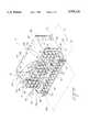
- FIG. 2is a perspective view, with some portions broken away, of an optical fiber connector housing according to one aspect of the present invention
- FIG. 3is a simplified perspective view, similar to FIG. 2, showing the side and top aperatures of a connector housing according to one embodiment of the present invention
- FIG. 4ais a simplified perspective view showing another embodiment of a connector housing according to the present invention.
- FIG. 4bis a simplified perspective view showing still another embodiment of a connector housing according to the present invention.
- FIG. 1a front view of a fiber optic distribution center 20 is shown which can incorporate a optical fiber connector housing according to the current invention.
- the typical distribution center 20comprises one or more vertical equipment stacks 22, also known as "bays", each comprising several components supported by vertical frame members 24.
- the frame members 24may be attached to a wall or free standing on the floor.
- the distribution facility shown in FIG. 1comprises two equipment bays 22, however it will be readily apparent that the numbers of bays to be used will be dependant on the number of connections required in the distribution facility.
- an interbay storage unit 25may be positioned between bays 22 to further aid in cable management.
- each equipment bay 22typically includes at least one optical fiber connector housing 26 and at least one horizontal raceway 28 positioned above and adjacent each connector housing 26.
- each equipment bay 22has two connector housings 26 and two horizontal raceways 28. It should be noted, however, that while it is preferred to use horizontal raceways 28 in conjunction with connector housings 26, the use of horizontal raceways is optional, and connector housings 26 may be used alone or in conjunction with other equipment depending on the needs of the user.
- splice housings(not shown) and other equipment may be included in the equipment bays 22 as dictated by the needs of the user.
- each connector housing 26includes a connector panel 30 for interconnecting individual optical fibers 32 at the front side of connector panel 30 to other optical fibers (not shown) at the rear side of connector panel 30.
- Connector housing 26can further include cable management brackets 34 positioned below the connector panel to facilitate in the routing of optical fibers 32 toward the side of connector housing 26.
- each horizontal raceway 28can also include cable management brackets 36 to facilitate the routing of optical fibers 32 from connector panel 30 through the top of the connector housing 26.
- the optical fibers 32 from each connector housing 26can then be routed via the horizontal raceways 28 and the interbay storage unit 25 to other connector housings 26 in the distribution facility 20 or to optical cables for interconnection with other parts of the user's facility.
- a door 36(best seen on housings marked 26b) is shut over the forward cable area of each connector housing 26 to protect the fibers and connectors from damage due to excessive bending, excessive tension, or physical damage from the external environment.
- protective covers 38can be affixed on horizontal raceways 28 (best seen in horizontal raceways marked 28b) to further protect the optical fibers routed therethrough.
- Connector housing 26comprises upper and lower plate members 40, 42, respectively, a connector panel 30, a door 36, and a means 44 for releasably securing the door 36 in a closed position.
- Upper and lower plate members 40, 42are generally horizontal and spaced apart from one another.
- the plate members 40, 42are adapted for attachment to a supporting frame. In the embodiment shown in FIG.
- the upper and lower plate members 40, 42can be attached to the supporting frame (not shown) by means of mounting holes 46 formed in the side plates 48 connected between the plate members 40 and 42, by mounting holes 50 formed in connector panel 30 connected to plate members 40, 42, or by other means of connection known in the art.
- Upper and lower plate members 40, 42each have front edges 52, 54, respectively, and rear edges 56, 58, respectively, with the front edge 54 of the lower plate member 42 extending further forward than the front edge 52 of the upper plate member 40.
- the connector panel 30depends generally vertically downward from the front edge 52 of the upper plate member 40 and is connected to the lower plate member 42 along an attachment line 60 which is rearwardly disposed with respect to the front edge 54 of the lower plate member 42, thereby defining a shelf portion 62 and a rear portion 64 of the lower plate member 42.
- the shelf portion 62 of lower plate member 42is between the front edge 54 of the lower plate member 42 and the attachment line 60 and the rear portion 64 of the lower plate member 42 is between the attachment line 60 and the rear edge 58 of the lower plate member 42.
- Connector panel 30has a front face 66 and a rear face 68 and is adapted for mounting therethrough a plurality of optical fiber adaptors 70 of the type wherein each adaptor has a front side 72 and a rear side 74 and is adapted for receiving and mounting in optical alignment a pair of optical fibers 32 being routed to opposite sides of the adaptor 70 and each being terminated with a connector 76.
- optical fiber adaptors and connectorsare well known in the art and are available in a variety of configurations.
- the connector panel 30is adapted for mounting a plurality of connector modules 78 each including three duplex optical fiber adaptors 70, thus allowing each module 78 to accommodate six optical fiber connections.
- Each connector module 78is mounted to the connector panel 30 by means of quick release fasteners 80 which are inserted into mounting holes 82 on connector panel 30.
- the connector panel 30can mount up to 12 connector modules 78 for providing a total of 72 optical fiber connections, however, three connector modules have been removed in FIG. 2 for the purposes of illustration so that connections on the rear side of connector panel 30 can be seen.
- the door 36has top and bottom edges 84 and 86, respectively, and side edges 88.
- the door 36is hingeably connected at the bottom edge 86 to the front edge 54 of the lower plate member 42 and is thereby moveable between a closed position (shown as 36a) and an open position (shown as 36b in phantom).
- two hinges 90are used for connection of door 36 to lower plate member 42.
- the door 36when in the closed position, has a generally vertically orientation and is spaced from and generally parallel with the connector panel 30, thereby defining a forward cable area 92, at least one side aperture 94, and at least one top aperture 96.
- the forward cable area 92is bounded by the door 36, the front face 66 of the connector panel 30, and the shelf portion 62 of the lower plate member 42.
- the side aperture 94is defined as being between the side edge 88 of the door 36 and the front face 66 of the connector panel 30.
- the top aperture 96is defined as being between the top edge 84 of the door 36 and the front face 66 of the connector panel 30.
- a means 44 for releaseably securing the door 36 in the closed positionis also provided.
- the securing meanscomprises a bracket 98 extending from connector panel 30 and releaseably interfitting with a latch mechanism 100 mounted on the door 36, however, it will be readily apparent that other mechanisms known in the art for holding the door 36 in the closed position could be substituted for the bracket and latch mechanism shown in FIG. 2 without departing from the scope of the invention, including other types of mechanical latches, magnetic latches, hook and loop material (such as Velcro®), and latches and hinges having mechanical detents.
- a hinged door 36is preferred, in alternative embodiments of the current invention, a sliding door or a completely removable door or panel could be used as long as it can be vertically oriented and vertically aligned with the connector panel 30 when in the closed position.
- a plurality of optic fibers 32 each being terminated with a connector 76may be connected to the rear side 74 of adaptors 70 of connector panel 30.
- the fiber marked 32ahas been routed through side plate 48 and is connected to the middle adaptor of a connector module 78 while the optical fiber marked 32b has been routed through a slot 101 formed in the upper plate member 40 and is connected to the lower adaptor in the same connector module.
- a plurality of optical fibers 32may be connected to the front side 72 of adaptors 70 on the connector panel 30 and advantageously routed out of the forward cable area 92 by routing a first portion of the plurality of fibers through at least one side aperture 94 and routing a second portion of the plurality of fibers through at least one top aperture 96.
- the optical fiber marked 32cis connected to the front side 72 of the middle adaptor, thus interconnecting it with optical fiber 32a.
- Optical fiber 32cis then routed out of forward cable area 92 by means of top aperture 96.
- optical fiber 32dis connected to the front side 72 of the lower adaptor, thereby interconnecting it with optical fiber 32b.
- Optical fiber 32dis routed from forward cable area 92 by means of the cable management bracket 34 and the side aperture 94.
- FIG. 2shows only two optical fibers 32 being connected and routed out of forward cable area 92, however, it will be readily apparent that the entire array of adaptors from connector panel 30 could be populated by optical fibers which could then be routed as necessary from forward cable area 92 out the side aperture 94 and out the top aperture 96 as determined by the installer.
- optical fibers passing through top aperture 96could be fed directly into an above adjacent horizontal raceway 28 while optical fibers exiting by way of the side aperture 94, could be routed directly to a interbay storage unit 25.
- a connector housing 26allows the routing of optical fibers so as to reduce the density of fibers routed in each direction (i.e., vertically and laterally) while the closed door 36 protects the connectors 76, adaptors 70, and optical fibers 32 from damage and maintains the minimum required bend radius of the optical fibers.
- the door 36is selectively detachable from lower plate member 42 when the door is in the open position. This makes initial installation of the optical cables 32 easier for the technicians since the door does not get in the way. Once the initial installation is complete, the door 36 can be replaced so that the connectors 76 and optical fibers 32 are protected from damage.
- any of the detachable hinge mechanisms known in the artmay be used to allow the selective detachment of the door 36 from the lower plate 42.
- door 36comprises a transparent material which allows visual inspection in the forward cable area 92 when the door 36 is in the closed position.
- the transparent materialis an impact-resistant plastic which provides breakage resistance as well as allowing inspection of the contents of the forward cable area, however, the transparent material of door 36 may also be a glass.
- the transparent material of door 36may be tinted or coated with other materials so as to affect light transmission therethrough.
- the optical fiber connector housing 26may further comprise a rear plate member 102 connected to a rear portion of the housing to enclose a rear cable area 104.
- the rear cable area 104is bounded by the upper plate 40, the rear portion 64 of the lower plate 42, side members 48, the rear face 68 of the connector panel 30, and by rear plate member 102, if used.
- the use of a rear plate member 102 to enclose the rear cable area 104is optional; however, it helps protect the optical fibers on the rear side of the connector panel.
- FIGS. 4A and 4Bit will be readily appreciated that essentially the same benefits may be obtained from an alternative connector housing 106 such as shown in FIG. 4A, which has been vertically "inverted", from the configuration shown in FIG. 2 such that the extending shelf section 108 of the connector housing is on the upper plate member rather than on the lower plate member and the door 110 opens towards the top rather than towards the bottom.
- a second alternative connector housing 112 shown in FIG. 4Bwould have the extending shelf member 114 oriented vertically with the door 116 opening to the side as shown in FIG. 4B. It will be readily apparent that the use of these alternative embodiments such as shown in FIG. 4A and FIG. 4B would require the repositioning or reorientation of raceways or other equipment to derive the maximum benefit from the optical fiber routing options made available by the current invention.
Landscapes
- Physics & Mathematics (AREA)
- General Physics & Mathematics (AREA)
- Optics & Photonics (AREA)
- Light Guides In General And Applications Therefor (AREA)
Abstract
Description
Claims (11)
Priority Applications (4)
| Application Number | Priority Date | Filing Date | Title |
|---|---|---|---|
| US08/777,227US5778130A (en) | 1996-12-31 | 1996-12-31 | Optical fiber connector housing |
| CA002221938ACA2221938C (en) | 1996-12-31 | 1997-11-19 | Optical fiber connector housing |
| EP97310466AEP0851257B1 (en) | 1996-12-31 | 1997-12-22 | Optical fiber connector housing |
| DE69739551TDE69739551D1 (en) | 1996-12-31 | 1997-12-22 | Optical fiber connection housing |
Applications Claiming Priority (1)
| Application Number | Priority Date | Filing Date | Title |
|---|---|---|---|
| US08/777,227US5778130A (en) | 1996-12-31 | 1996-12-31 | Optical fiber connector housing |
Publications (1)
| Publication Number | Publication Date |
|---|---|
| US5778130Atrue US5778130A (en) | 1998-07-07 |
Family
ID=25109649
Family Applications (1)
| Application Number | Title | Priority Date | Filing Date |
|---|---|---|---|
| US08/777,227Expired - LifetimeUS5778130A (en) | 1996-12-31 | 1996-12-31 | Optical fiber connector housing |
Country Status (4)
| Country | Link |
|---|---|
| US (1) | US5778130A (en) |
| EP (1) | EP0851257B1 (en) |
| CA (1) | CA2221938C (en) |
| DE (1) | DE69739551D1 (en) |
Cited By (90)
| Publication number | Priority date | Publication date | Assignee | Title |
|---|---|---|---|---|
| US5937130A (en)* | 1998-04-20 | 1999-08-10 | Amberg; Mark F. | Method and apparatus for installing fiber optic jumper cables in an equipment enclosure |
| US5987203A (en)* | 1997-10-09 | 1999-11-16 | Lucent Technologies Inc. | Distribution module for optical couplings |
| US6064791A (en)* | 1998-04-24 | 2000-05-16 | New York Telephone | Restoration of loose tube fiber optic cable |
| EP1039326A1 (en)* | 1999-03-19 | 2000-09-27 | Siecor Operations, LLC | Panel for managing jumper storage |
| US6254278B1 (en)* | 1999-10-06 | 2001-07-03 | Lucent Technologies Inc. | Optical fiber tunable connector adapter |
| US6314230B1 (en)* | 2000-03-08 | 2001-11-06 | Avaya Technology Corp. | Fiber interconnection assembly |
| US6347963B1 (en) | 1999-12-22 | 2002-02-19 | Cisco Technology, Inc. | Interchangeable backplane interface connection panel |
| US6418262B1 (en)* | 2000-03-13 | 2002-07-09 | Adc Telecommunications, Inc. | Fiber distribution frame with fiber termination blocks |
| USD465455S1 (en) | 2000-12-11 | 2002-11-12 | Fiber Optic Network Solutions Corporation | Module for fiber optic equipment |
| US20020181924A1 (en)* | 2000-12-22 | 2002-12-05 | Fiber Optic Network Solutions, Inc. | Module and housing for DWDM equipment |
| US6515227B1 (en) | 2002-05-24 | 2003-02-04 | Alcoa Fujikura Limited | Fiber optic cable management enclosure with integral bend radius control |
| US6526210B1 (en)* | 2000-06-27 | 2003-02-25 | Cisco Technology, Inc. | Optical connector retainer panel and system |
| US6553172B2 (en)* | 2001-06-08 | 2003-04-22 | Ceyba Inc. | Fiber optic cable routing device with pre-alignment feature |
| US20030087505A1 (en)* | 2000-11-14 | 2003-05-08 | Peter Deane | Method and apparatus for adapting a miniature form-factor connector to a standard format fiber optic connector plug |
| US6591053B2 (en) | 2000-03-08 | 2003-07-08 | Panduit Corp. | Fiber optic wall mount cabinet |
| US6600106B2 (en)* | 2001-07-11 | 2003-07-29 | Adc Telecommunications, Inc. | Cable management bar and patch panel |
| US20030174996A1 (en)* | 2002-03-15 | 2003-09-18 | Fiber Optic Network Solutions, Inc. | Optical fiber enclosure system using integrated optical connector and coupler assembly |
| US6633717B1 (en)* | 2000-09-08 | 2003-10-14 | Telect, Inc. | High density fiber optic cable distribution frame system |
| WO2003101074A3 (en)* | 2002-05-23 | 2004-01-29 | 3M Innovative Properties Co | Cover plates for adsl-splitter positions in modular distribution frames |
| US6728461B1 (en) | 2003-03-13 | 2004-04-27 | Marc Senatore | Optical fiber cable manager |
| US20040094491A1 (en)* | 2002-11-15 | 2004-05-20 | Smith Trevor D. | Cable management assembly, system and method |
| US20050111810A1 (en)* | 2003-11-26 | 2005-05-26 | Giraud William J. | Connector housing for a communication network |
| US20050111809A1 (en)* | 2003-11-26 | 2005-05-26 | Giraud William J. | Connector housing having a sliding tray with a hingeable portion |
| US20050191901A1 (en)* | 1998-06-05 | 2005-09-01 | Adc Telecommunications, Inc. | Telecommunications patch panel with angled connector modules |
| US20050284651A1 (en)* | 2004-06-29 | 2005-12-29 | Lite-On Technology Corp. | Space structure for tidying up cables connecting to an electronic appliance |
| US20060032990A1 (en)* | 2004-08-11 | 2006-02-16 | Cask John A | Rack and duct system |
| US7091418B1 (en) | 2005-04-01 | 2006-08-15 | Adc Telecommunications, Inc. | Cable management bar and patch panel |
| US20060228087A1 (en)* | 2005-04-07 | 2006-10-12 | Yilmaz Bayazit | Cable management assembly, system and method |
| WO2007050470A1 (en)* | 2005-10-24 | 2007-05-03 | 3M Innovative Properties Company | Optical connector, fiber distribution unit, and fiber termination platform for optical connectors |
| US20070189693A1 (en)* | 2006-02-16 | 2007-08-16 | Mark Smrha | Cable management device and method |
| US20080050085A1 (en)* | 2006-08-25 | 2008-02-28 | Tinucci Thomas C | Cable management system with spring latch |
| US20080050083A1 (en)* | 2006-08-25 | 2008-02-28 | Frazier Brent M | Fiber optic housing assembly for fiber optic connections comprising pivotable portion |
| US20080050084A1 (en)* | 2006-08-25 | 2008-02-28 | Sjodin Chad J | Cable management system with twist latch |
| US20080273842A1 (en)* | 2005-08-31 | 2008-11-06 | Nippon Telegraph And Telephone Corporation | Optical Connector |
| US20080293294A1 (en)* | 2006-06-22 | 2008-11-27 | Adc Telecommunications, Inc. | Telecommunications patch |
| US20080298763A1 (en)* | 2007-05-31 | 2008-12-04 | Mark David Appenzeller | Telecommunications housing with optical fiber management |
| US20090097813A1 (en)* | 2007-10-01 | 2009-04-16 | John Paul Hill | Modular optical fiber cassettes and fiber management methods |
| US20090324189A1 (en)* | 2007-10-01 | 2009-12-31 | Clearfield, Inc. | Modular optical fiber cassette |
| US20100142910A1 (en)* | 2007-10-01 | 2010-06-10 | Clearfield, Inc. | Modular optical fiber cassette |
| US20100209065A1 (en)* | 2009-02-18 | 2010-08-19 | Gil Ruiz | Optical fiber management shelf including door with push-push fastener |
| US20100301720A1 (en)* | 2009-05-12 | 2010-12-02 | Chad Anderson | Cable management module with pivot cover assembly |
| US20110030190A1 (en)* | 2009-08-06 | 2011-02-10 | 3M Innovative Properties Company | System and method for providing final drop in a living unit in a building |
| US20120049711A1 (en)* | 2010-08-27 | 2012-03-01 | Gil Ruiz | Fiber Optic Enclosure Having Tamper Resistant Lock |
| US8433171B2 (en) | 2009-06-19 | 2013-04-30 | Corning Cable Systems Llc | High fiber optic cable packing density apparatus |
| US8457464B2 (en) | 2011-09-26 | 2013-06-04 | Hubbell Incorporated | Cable enclosure and radius-limiting cable guide with integral magnetic door catch |
| US8538226B2 (en) | 2009-05-21 | 2013-09-17 | Corning Cable Systems Llc | Fiber optic equipment guides and rails configured with stopping position(s), and related equipment and methods |
| US8542973B2 (en) | 2010-04-23 | 2013-09-24 | Ccs Technology, Inc. | Fiber optic distribution device |
| US8593828B2 (en) | 2010-02-04 | 2013-11-26 | Corning Cable Systems Llc | Communications equipment housings, assemblies, and related alignment features and methods |
| US8625950B2 (en) | 2009-12-18 | 2014-01-07 | Corning Cable Systems Llc | Rotary locking apparatus for fiber optic equipment trays and related methods |
| WO2014008338A1 (en)* | 2012-07-03 | 2014-01-09 | Nitro Fiber | Optical fiber connectivity management system |
| US8660397B2 (en) | 2010-04-30 | 2014-02-25 | Corning Cable Systems Llc | Multi-layer module |
| US8662760B2 (en) | 2010-10-29 | 2014-03-04 | Corning Cable Systems Llc | Fiber optic connector employing optical fiber guide member |
| US8699838B2 (en) | 2009-05-14 | 2014-04-15 | Ccs Technology, Inc. | Fiber optic furcation module |
| US8705926B2 (en) | 2010-04-30 | 2014-04-22 | Corning Optical Communications LLC | Fiber optic housings having a removable top, and related components and methods |
| US8712206B2 (en) | 2009-06-19 | 2014-04-29 | Corning Cable Systems Llc | High-density fiber optic modules and module housings and related equipment |
| US8718436B2 (en) | 2010-08-30 | 2014-05-06 | Corning Cable Systems Llc | Methods, apparatuses for providing secure fiber optic connections |
| US8879881B2 (en) | 2010-04-30 | 2014-11-04 | Corning Cable Systems Llc | Rotatable routing guide and assembly |
| US8913866B2 (en) | 2010-03-26 | 2014-12-16 | Corning Cable Systems Llc | Movable adapter panel |
| US8953924B2 (en) | 2011-09-02 | 2015-02-10 | Corning Cable Systems Llc | Removable strain relief brackets for securing fiber optic cables and/or optical fibers to fiber optic equipment, and related assemblies and methods |
| US8985862B2 (en) | 2013-02-28 | 2015-03-24 | Corning Cable Systems Llc | High-density multi-fiber adapter housings |
| US8989547B2 (en) | 2011-06-30 | 2015-03-24 | Corning Cable Systems Llc | Fiber optic equipment assemblies employing non-U-width-sized housings and related methods |
| US8995812B2 (en) | 2012-10-26 | 2015-03-31 | Ccs Technology, Inc. | Fiber optic management unit and fiber optic distribution device |
| US9008485B2 (en) | 2011-05-09 | 2015-04-14 | Corning Cable Systems Llc | Attachment mechanisms employed to attach a rear housing section to a fiber optic housing, and related assemblies and methods |
| US9020320B2 (en) | 2008-08-29 | 2015-04-28 | Corning Cable Systems Llc | High density and bandwidth fiber optic apparatuses and related equipment and methods |
| US9022814B2 (en) | 2010-04-16 | 2015-05-05 | Ccs Technology, Inc. | Sealing and strain relief device for data cables |
| US9038832B2 (en) | 2011-11-30 | 2015-05-26 | Corning Cable Systems Llc | Adapter panel support assembly |
| US9042702B2 (en) | 2012-09-18 | 2015-05-26 | Corning Cable Systems Llc | Platforms and systems for fiber optic cable attachment |
| US9059578B2 (en) | 2009-02-24 | 2015-06-16 | Ccs Technology, Inc. | Holding device for a cable or an assembly for use with a cable |
| US9075216B2 (en) | 2009-05-21 | 2015-07-07 | Corning Cable Systems Llc | Fiber optic housings configured to accommodate fiber optic modules/cassettes and fiber optic panels, and related components and methods |
| US9075217B2 (en) | 2010-04-30 | 2015-07-07 | Corning Cable Systems Llc | Apparatuses and related components and methods for expanding capacity of fiber optic housings |
| US20150295655A1 (en)* | 2014-04-10 | 2015-10-15 | Corning Optical Communications LLC | Optical interconnection assemblies supporting multiplexed data signals, and related components, methods and systems |
| US9213161B2 (en) | 2010-11-05 | 2015-12-15 | Corning Cable Systems Llc | Fiber body holder and strain relief device |
| US9250409B2 (en) | 2012-07-02 | 2016-02-02 | Corning Cable Systems Llc | Fiber-optic-module trays and drawers for fiber-optic equipment |
| US9279951B2 (en) | 2010-10-27 | 2016-03-08 | Corning Cable Systems Llc | Fiber optic module for limited space applications having a partially sealed module sub-assembly |
| US9519118B2 (en) | 2010-04-30 | 2016-12-13 | Corning Optical Communications LLC | Removable fiber management sections for fiber optic housings, and related components and methods |
| US9632270B2 (en) | 2010-04-30 | 2017-04-25 | Corning Optical Communications LLC | Fiber optic housings configured for tool-less assembly, and related components and methods |
| US9645317B2 (en) | 2011-02-02 | 2017-05-09 | Corning Optical Communications LLC | Optical backplane extension modules, and related assemblies suitable for establishing optical connections to information processing modules disposed in equipment racks |
| US9720195B2 (en) | 2010-04-30 | 2017-08-01 | Corning Optical Communications LLC | Apparatuses and related components and methods for attachment and release of fiber optic housings to and from an equipment rack |
| US10067309B2 (en) | 1999-03-01 | 2018-09-04 | Commscope Technologies Llc | Optical fiber distribution frame with outside plant enclosure |
| US10094996B2 (en) | 2008-08-29 | 2018-10-09 | Corning Optical Communications, Llc | Independently translatable modules and fiber optic equipment trays in fiber optic equipment |
| US10126509B2 (en) | 2004-06-18 | 2018-11-13 | Commscope Technologies Llc | Telecommunications cabinet with connector storage |
| US10151896B2 (en) | 2003-07-02 | 2018-12-11 | CommScope Technologies, LLC | Telecommunications connection cabinet |
| US10168491B2 (en) | 2003-06-30 | 2019-01-01 | Commscope Technologies Llc | Fiber optic connector holder and method |
| US10393980B2 (en) | 2003-11-17 | 2019-08-27 | Commscope Technologies Llc | Fiber distribution device |
| US10416406B1 (en) | 2018-03-01 | 2019-09-17 | Afl Telecommunications Llc | Communications module housing |
| US10451828B1 (en) | 2018-11-09 | 2019-10-22 | Afl Telecommunications Llc | Communications module housing |
| US11294136B2 (en) | 2008-08-29 | 2022-04-05 | Corning Optical Communications LLC | High density and bandwidth fiber optic apparatuses and related equipment and methods |
| US11493717B2 (en)* | 2020-07-31 | 2022-11-08 | Google Llc | Fiber optic cable distribution and management system |
| US20230010285A1 (en)* | 2021-07-12 | 2023-01-12 | Ciena Corporation | Auxiliary cable organization structure for network rack system |
| US20240114665A1 (en)* | 2021-06-29 | 2024-04-04 | Ciena Corporation | Front-to-rear airflow assembly for an equipment casing mounted on a rack |
Families Citing this family (10)
| Publication number | Priority date | Publication date | Assignee | Title |
|---|---|---|---|---|
| US6160946A (en) | 1998-07-27 | 2000-12-12 | Adc Telecommunications, Inc. | Outside plant fiber distribution apparatus and method |
| US7120347B2 (en) | 2004-01-27 | 2006-10-10 | Corning Cable Systems Llc | Multi-port optical connection terminal |
| CA2558996A1 (en) | 2004-03-08 | 2005-09-22 | Adc Telecommunications, Inc. | Fiber access terminal |
| US7489849B2 (en) | 2004-11-03 | 2009-02-10 | Adc Telecommunications, Inc. | Fiber drop terminal |
| US7740409B2 (en) | 2007-09-19 | 2010-06-22 | Corning Cable Systems Llc | Multi-port optical connection terminal |
| EP2198328B1 (en) | 2007-10-09 | 2018-09-26 | ADC Telecommunications, INC. | Mini drop terminal |
| US7903923B2 (en) | 2007-10-09 | 2011-03-08 | Adc Telecommunications, Inc. | Drop terminal releasable engagement mechanism |
| WO2012058391A1 (en) | 2010-10-28 | 2012-05-03 | Corning Cable Systems Llc | Impact resistant fiber optic enclosures and related methods |
| US9069151B2 (en) | 2011-10-26 | 2015-06-30 | Corning Cable Systems Llc | Composite cable breakout assembly |
| US8873926B2 (en) | 2012-04-26 | 2014-10-28 | Corning Cable Systems Llc | Fiber optic enclosures employing clamping assemblies for strain relief of cables, and related assemblies and methods |
Citations (14)
| Publication number | Priority date | Publication date | Assignee | Title |
|---|---|---|---|---|
| US4630886A (en)* | 1984-04-16 | 1986-12-23 | At&T Bell Laboratories | Lightguide distributing unit |
| US4708430A (en)* | 1984-10-25 | 1987-11-24 | Northern Telecom Limited | Cabinet for optical cable terminating equipment |
| US4824196A (en)* | 1987-05-26 | 1989-04-25 | Minnesota Mining And Manufacturing Company | Optical fiber distribution panel |
| US4911662A (en)* | 1988-12-20 | 1990-03-27 | Northern Telecom Limited | Distribution frame for telecommunications cable |
| US4971421A (en)* | 1989-09-29 | 1990-11-20 | Reliance Comm/Tec Corporation | Fiber optic splice and patch enclosure |
| US5093885A (en)* | 1990-07-11 | 1992-03-03 | Adc Telecommunications, Inc. | Fiber optic connector module |
| US5100221A (en)* | 1990-01-22 | 1992-03-31 | Porta Systems Corp. | Optical fiber cable distribution frame and support |
| US5129030A (en)* | 1991-05-30 | 1992-07-07 | At&T Bell Laboratories | Movable lightguide connector panel |
| US5179618A (en)* | 1990-07-11 | 1993-01-12 | Adc Telecommunications, Inc. | Fiber optic connector module |
| US5339379A (en)* | 1993-06-18 | 1994-08-16 | Telect, Inc. | Telecommunication fiber optic cable distribution apparatus |
| US5363465A (en)* | 1993-02-19 | 1994-11-08 | Adc Telecommunications, Inc. | Fiber optic connector module |
| US5402515A (en)* | 1994-03-01 | 1995-03-28 | Minnesota Mining And Manufacturing Company | Fiber distribution frame system, cabinets, trays and fiber optic connector couplings |
| USRE34955E (en)* | 1989-07-31 | 1995-05-30 | Adc Telecommunications, Inc. | Optical fiber distribution frame |
| US5442726A (en)* | 1994-02-22 | 1995-08-15 | Hubbell Incorporated | Optical fiber storage system |
Family Cites Families (4)
| Publication number | Priority date | Publication date | Assignee | Title |
|---|---|---|---|---|
| US5142607A (en)* | 1990-03-20 | 1992-08-25 | Rittal-Werk Rudolf Loh Gmbh & Co. Kg | Splice box for optical wave guide |
| US5442725A (en)* | 1993-08-30 | 1995-08-15 | At&T Corp. | Pivotally mounted tray for organizing optical fibers |
| DE4413136C1 (en)* | 1994-04-19 | 1995-05-04 | Loh Kg Rittal Werk | Optical-fibre splice box |
| US5506927A (en)* | 1995-01-24 | 1996-04-09 | Nec Corporation | Framework for housing optical equipment having optical fiber cable |
- 1996
- 1996-12-31USUS08/777,227patent/US5778130A/ennot_activeExpired - Lifetime
- 1997
- 1997-11-19CACA002221938Apatent/CA2221938C/ennot_activeExpired - Lifetime
- 1997-12-22EPEP97310466Apatent/EP0851257B1/ennot_activeExpired - Lifetime
- 1997-12-22DEDE69739551Tpatent/DE69739551D1/ennot_activeExpired - Lifetime
Patent Citations (14)
| Publication number | Priority date | Publication date | Assignee | Title |
|---|---|---|---|---|
| US4630886A (en)* | 1984-04-16 | 1986-12-23 | At&T Bell Laboratories | Lightguide distributing unit |
| US4708430A (en)* | 1984-10-25 | 1987-11-24 | Northern Telecom Limited | Cabinet for optical cable terminating equipment |
| US4824196A (en)* | 1987-05-26 | 1989-04-25 | Minnesota Mining And Manufacturing Company | Optical fiber distribution panel |
| US4911662A (en)* | 1988-12-20 | 1990-03-27 | Northern Telecom Limited | Distribution frame for telecommunications cable |
| USRE34955E (en)* | 1989-07-31 | 1995-05-30 | Adc Telecommunications, Inc. | Optical fiber distribution frame |
| US4971421A (en)* | 1989-09-29 | 1990-11-20 | Reliance Comm/Tec Corporation | Fiber optic splice and patch enclosure |
| US5100221A (en)* | 1990-01-22 | 1992-03-31 | Porta Systems Corp. | Optical fiber cable distribution frame and support |
| US5179618A (en)* | 1990-07-11 | 1993-01-12 | Adc Telecommunications, Inc. | Fiber optic connector module |
| US5093885A (en)* | 1990-07-11 | 1992-03-03 | Adc Telecommunications, Inc. | Fiber optic connector module |
| US5129030A (en)* | 1991-05-30 | 1992-07-07 | At&T Bell Laboratories | Movable lightguide connector panel |
| US5363465A (en)* | 1993-02-19 | 1994-11-08 | Adc Telecommunications, Inc. | Fiber optic connector module |
| US5339379A (en)* | 1993-06-18 | 1994-08-16 | Telect, Inc. | Telecommunication fiber optic cable distribution apparatus |
| US5442726A (en)* | 1994-02-22 | 1995-08-15 | Hubbell Incorporated | Optical fiber storage system |
| US5402515A (en)* | 1994-03-01 | 1995-03-28 | Minnesota Mining And Manufacturing Company | Fiber distribution frame system, cabinets, trays and fiber optic connector couplings |
Cited By (178)
| Publication number | Priority date | Publication date | Assignee | Title |
|---|---|---|---|---|
| US5987203A (en)* | 1997-10-09 | 1999-11-16 | Lucent Technologies Inc. | Distribution module for optical couplings |
| US5937130A (en)* | 1998-04-20 | 1999-08-10 | Amberg; Mark F. | Method and apparatus for installing fiber optic jumper cables in an equipment enclosure |
| US6064791A (en)* | 1998-04-24 | 2000-05-16 | New York Telephone | Restoration of loose tube fiber optic cable |
| US8491331B2 (en) | 1998-06-05 | 2013-07-23 | Adc Telecommunications, Inc. | Telecommunications patch panel with angled connector modules |
| US7244144B2 (en) | 1998-06-05 | 2007-07-17 | Adc Telecommunications, Inc. | Telecommunications patch panel with angled connector modules |
| US9033728B2 (en) | 1998-06-05 | 2015-05-19 | Adc Telecommunications, Inc. | Telecommunications patch panel with angled connector modules |
| US9356384B2 (en) | 1998-06-05 | 2016-05-31 | Commscope Technologies Llc | Telecommunications patch panel with angled connector modules |
| US9755381B2 (en) | 1998-06-05 | 2017-09-05 | Commscope Technologies Llc | Telecommunications patch panel with angled connector modules |
| US7179119B2 (en) | 1998-06-05 | 2007-02-20 | Adc Telecommunications, Inc. | Telecommunications patch panel with angled connector modules |
| US20060025011A1 (en)* | 1998-06-05 | 2006-02-02 | Adc Telecommunications, Inc. | Telecommunications patch panel with angled connector modules |
| US20050191901A1 (en)* | 1998-06-05 | 2005-09-01 | Adc Telecommunications, Inc. | Telecommunications patch panel with angled connector modules |
| US10067309B2 (en) | 1999-03-01 | 2018-09-04 | Commscope Technologies Llc | Optical fiber distribution frame with outside plant enclosure |
| EP1039326A1 (en)* | 1999-03-19 | 2000-09-27 | Siecor Operations, LLC | Panel for managing jumper storage |
| US6353696B1 (en) | 1999-03-19 | 2002-03-05 | Corning Cable Systems Llc | Panel for managing jumper storage |
| US6254278B1 (en)* | 1999-10-06 | 2001-07-03 | Lucent Technologies Inc. | Optical fiber tunable connector adapter |
| US6347963B1 (en) | 1999-12-22 | 2002-02-19 | Cisco Technology, Inc. | Interchangeable backplane interface connection panel |
| US6591053B2 (en) | 2000-03-08 | 2003-07-08 | Panduit Corp. | Fiber optic wall mount cabinet |
| US6314230B1 (en)* | 2000-03-08 | 2001-11-06 | Avaya Technology Corp. | Fiber interconnection assembly |
| US6418262B1 (en)* | 2000-03-13 | 2002-07-09 | Adc Telecommunications, Inc. | Fiber distribution frame with fiber termination blocks |
| US6526210B1 (en)* | 2000-06-27 | 2003-02-25 | Cisco Technology, Inc. | Optical connector retainer panel and system |
| US6633717B1 (en)* | 2000-09-08 | 2003-10-14 | Telect, Inc. | High density fiber optic cable distribution frame system |
| US20030087505A1 (en)* | 2000-11-14 | 2003-05-08 | Peter Deane | Method and apparatus for adapting a miniature form-factor connector to a standard format fiber optic connector plug |
| US6802653B2 (en)* | 2000-11-14 | 2004-10-12 | National Semiconductor Corporation | Method and apparatus for adapting a miniature form-factor connector to a standard format fiber optic connector plug |
| USD465455S1 (en) | 2000-12-11 | 2002-11-12 | Fiber Optic Network Solutions Corporation | Module for fiber optic equipment |
| US6901200B2 (en) | 2000-12-22 | 2005-05-31 | Fiber Optic Network Solutions, Inc. | Module and housing for optical fiber distribution and DWDM equipment |
| US20020181924A1 (en)* | 2000-12-22 | 2002-12-05 | Fiber Optic Network Solutions, Inc. | Module and housing for DWDM equipment |
| US6553172B2 (en)* | 2001-06-08 | 2003-04-22 | Ceyba Inc. | Fiber optic cable routing device with pre-alignment feature |
| US6600106B2 (en)* | 2001-07-11 | 2003-07-29 | Adc Telecommunications, Inc. | Cable management bar and patch panel |
| US6909833B2 (en)* | 2002-03-15 | 2005-06-21 | Fiber Optic Network Solutions, Inc. | Optical fiber enclosure system using integrated optical connector and coupler assembly |
| US20030174996A1 (en)* | 2002-03-15 | 2003-09-18 | Fiber Optic Network Solutions, Inc. | Optical fiber enclosure system using integrated optical connector and coupler assembly |
| US20050023020A1 (en)* | 2002-05-23 | 2005-02-03 | Friedrich Denter | Cover plates for ADSL-splitter positions in modular distribution frames |
| WO2003101074A3 (en)* | 2002-05-23 | 2004-01-29 | 3M Innovative Properties Co | Cover plates for adsl-splitter positions in modular distribution frames |
| US6515227B1 (en) | 2002-05-24 | 2003-02-04 | Alcoa Fujikura Limited | Fiber optic cable management enclosure with integral bend radius control |
| US7083051B2 (en) | 2002-11-15 | 2006-08-01 | Adc Telecommunications, Inc. | Cable management assembly, system and method |
| US8403154B2 (en) | 2002-11-15 | 2013-03-26 | Adc Telecommunications, Inc. | Cable management assembly, system and method |
| US8127941B2 (en) | 2002-11-15 | 2012-03-06 | Adc Telecommunications, Inc. | Cable management assembly, system and method |
| US20040094491A1 (en)* | 2002-11-15 | 2004-05-20 | Smith Trevor D. | Cable management assembly, system and method |
| US20060237377A1 (en)* | 2002-11-15 | 2006-10-26 | Adc Telecommunications | Cable management assembly, system and method |
| US20100314340A1 (en)* | 2002-11-15 | 2010-12-16 | Adc Telecommunications, Inc. | Cable management assembly, system and method |
| US7748541B2 (en) | 2002-11-15 | 2010-07-06 | Adc Telecommunications, Inc. | Cable management assembly, system and method |
| US20090223909A1 (en)* | 2002-11-15 | 2009-09-10 | Adc Telecommunications, Inc. | Cable management assembly, system and method |
| US7513374B2 (en) | 2002-11-15 | 2009-04-07 | Adc Telecommunications, Inc. | Cable management assembly, system and method |
| US20080116153A1 (en)* | 2002-11-15 | 2008-05-22 | Adc Telecommunications | Cable management assembly, system and method |
| US7331473B2 (en) | 2002-11-15 | 2008-02-19 | Adc Telecommunications, Inc. | Cable management assembly, system and method |
| US6728461B1 (en) | 2003-03-13 | 2004-04-27 | Marc Senatore | Optical fiber cable manager |
| US11119285B2 (en) | 2003-06-30 | 2021-09-14 | Commscope Technologies Llc | Fiber optic connector holder and method |
| US10168491B2 (en) | 2003-06-30 | 2019-01-01 | Commscope Technologies Llc | Fiber optic connector holder and method |
| US10634860B2 (en) | 2003-06-30 | 2020-04-28 | Commscope Technologies Llc | Fiber optic connector holder and method |
| US10436998B2 (en) | 2003-07-02 | 2019-10-08 | Commscope Technologies Llc | Telecommunications connection cabinet |
| US10527809B2 (en) | 2003-07-02 | 2020-01-07 | Commscope Technologies Llc | Telecommunications connection cabinet |
| US10151896B2 (en) | 2003-07-02 | 2018-12-11 | CommScope Technologies, LLC | Telecommunications connection cabinet |
| US10782497B2 (en) | 2003-07-02 | 2020-09-22 | Commscope Technologies Llc | Telecommunications connection cabinet |
| US10371915B2 (en) | 2003-07-02 | 2019-08-06 | Commscope Technologies Llc | Telecommunications connection cabinet |
| US10782498B2 (en) | 2003-11-17 | 2020-09-22 | Commscope Technologies Llc | Fiber distribution device |
| US11579390B2 (en) | 2003-11-17 | 2023-02-14 | Commscope Technologies Llc | Fiber distribution device |
| US10393980B2 (en) | 2003-11-17 | 2019-08-27 | Commscope Technologies Llc | Fiber distribution device |
| US20050111809A1 (en)* | 2003-11-26 | 2005-05-26 | Giraud William J. | Connector housing having a sliding tray with a hingeable portion |
| US6944389B2 (en) | 2003-11-26 | 2005-09-13 | Corning Cable Systems Llc | Connector housing having a sliding tray with a hingeable portion |
| US7200316B2 (en)* | 2003-11-26 | 2007-04-03 | Corning Cable Systems Llc | Connector housing for a communication network |
| US20050111810A1 (en)* | 2003-11-26 | 2005-05-26 | Giraud William J. | Connector housing for a communication network |
| US10274686B2 (en) | 2004-06-18 | 2019-04-30 | Commscope Technologies Llc | Telecommunications cabinet with connector storage |
| US11428876B2 (en) | 2004-06-18 | 2022-08-30 | Commscope Technologies Llc | Telecommunications cabinet with connector storage |
| US10126509B2 (en) | 2004-06-18 | 2018-11-13 | Commscope Technologies Llc | Telecommunications cabinet with connector storage |
| US10809467B2 (en) | 2004-06-18 | 2020-10-20 | Commscope Technologies Llc | Telecommunications cabinet with connector storage |
| US10634859B2 (en) | 2004-06-18 | 2020-04-28 | Commscope Technologies Llc | Fiber optic connector holder unit |
| US10345539B2 (en) | 2004-06-18 | 2019-07-09 | Commscope Technologies Llc | Telecommunications cabinet with connector storage |
| US20050284651A1 (en)* | 2004-06-29 | 2005-12-29 | Lite-On Technology Corp. | Space structure for tidying up cables connecting to an electronic appliance |
| US20060032990A1 (en)* | 2004-08-11 | 2006-02-16 | Cask John A | Rack and duct system |
| US7091418B1 (en) | 2005-04-01 | 2006-08-15 | Adc Telecommunications, Inc. | Cable management bar and patch panel |
| US7200931B2 (en) | 2005-04-01 | 2007-04-10 | Adc Telecommunications, Inc. | Cable management bar and patch panel |
| US20060225912A1 (en)* | 2005-04-01 | 2006-10-12 | Adc Telecommunications, Inc. | Cable Management Bar and Patch Panel |
| US20060228087A1 (en)* | 2005-04-07 | 2006-10-12 | Yilmaz Bayazit | Cable management assembly, system and method |
| US7677400B2 (en) | 2005-04-07 | 2010-03-16 | Adc Telecommunications, Inc. | Cable management assembly, system and method |
| US8899424B2 (en) | 2005-04-07 | 2014-12-02 | Adc Telecommunications, Inc. | Cable management assembly, system and method |
| US20080273842A1 (en)* | 2005-08-31 | 2008-11-06 | Nippon Telegraph And Telephone Corporation | Optical Connector |
| US7824109B2 (en)* | 2005-08-31 | 2010-11-02 | Nippon Telegraph And Telephone Corporation | Optical connector |
| WO2007050470A1 (en)* | 2005-10-24 | 2007-05-03 | 3M Innovative Properties Company | Optical connector, fiber distribution unit, and fiber termination platform for optical connectors |
| US7280733B2 (en) | 2005-10-24 | 2007-10-09 | 3M Innovative Properties Company | Fiber termination platform for optical connectors |
| CN101297224B (en)* | 2005-10-24 | 2010-09-15 | 3M创新有限公司 | Optical fiber connector, optical fiber distribution device, and optical fiber termination platform for optical fiber connector |
| US7369738B2 (en) | 2005-10-24 | 2008-05-06 | 3M Innovative Properties Company | Optical connector and fiber distribution unit |
| US20070104445A1 (en)* | 2005-10-24 | 2007-05-10 | 3M Innovative Properties Company | Fiber termination platform for optical connectors |
| US20070104425A1 (en)* | 2005-10-24 | 2007-05-10 | 3M Innovative Properties Company | Optical connector and fiber distribution unit |
| US7298951B2 (en) | 2006-02-16 | 2007-11-20 | Adc Telecommunications, Inc. | Cable management device and method |
| US20070189693A1 (en)* | 2006-02-16 | 2007-08-16 | Mark Smrha | Cable management device and method |
| US7607938B2 (en)* | 2006-06-22 | 2009-10-27 | Adc Telecommunications | Telecommunications patch |
| US20080293294A1 (en)* | 2006-06-22 | 2008-11-27 | Adc Telecommunications, Inc. | Telecommunications patch |
| US20100081319A1 (en)* | 2006-06-22 | 2010-04-01 | Adc Telecommunications, Inc. | Telecommunications Patch |
| US7811122B2 (en) | 2006-06-22 | 2010-10-12 | Adc Telecommunications, Inc. | Telecommunications patch |
| US7369740B2 (en) | 2006-08-25 | 2008-05-06 | Adc Telecommunications, Inc. | Cable management system with spring latch |
| US7349615B2 (en) | 2006-08-25 | 2008-03-25 | Corning Cable Systems Llc | Fiber optic housing assembly for fiber optic connections comprising pivotable portion |
| US20080050085A1 (en)* | 2006-08-25 | 2008-02-28 | Tinucci Thomas C | Cable management system with spring latch |
| US20080050083A1 (en)* | 2006-08-25 | 2008-02-28 | Frazier Brent M | Fiber optic housing assembly for fiber optic connections comprising pivotable portion |
| US20080050084A1 (en)* | 2006-08-25 | 2008-02-28 | Sjodin Chad J | Cable management system with twist latch |
| US20100272409A1 (en)* | 2006-08-25 | 2010-10-28 | Adc Telecommunications, Inc. | Cable management system with twist latch |
| US7764857B2 (en) | 2006-08-25 | 2010-07-27 | Adc Telecommunications, Inc. | Cable management system with twist latch |
| US7620287B2 (en) | 2007-05-31 | 2009-11-17 | Corning Cable Systems Llc | Telecommunications housing with optical fiber management |
| US20080298763A1 (en)* | 2007-05-31 | 2008-12-04 | Mark David Appenzeller | Telecommunications housing with optical fiber management |
| US8059932B2 (en) | 2007-10-01 | 2011-11-15 | Clearfield, Inc. | Modular optical fiber cassette |
| US20100142910A1 (en)* | 2007-10-01 | 2010-06-10 | Clearfield, Inc. | Modular optical fiber cassette |
| US7751674B2 (en) | 2007-10-01 | 2010-07-06 | Clearfield, Inc. | Modular optical fiber cassettes and fiber management methods |
| US20090097813A1 (en)* | 2007-10-01 | 2009-04-16 | John Paul Hill | Modular optical fiber cassettes and fiber management methods |
| US8374477B2 (en) | 2007-10-01 | 2013-02-12 | Clearfield, Inc. | Modular optical fiber cassettes |
| US7945138B2 (en) | 2007-10-01 | 2011-05-17 | Clearfield, Inc. | Modular optical fiber cassette |
| US20090324189A1 (en)* | 2007-10-01 | 2009-12-31 | Clearfield, Inc. | Modular optical fiber cassette |
| US9910236B2 (en) | 2008-08-29 | 2018-03-06 | Corning Optical Communications LLC | High density and bandwidth fiber optic apparatuses and related equipment and methods |
| US11092767B2 (en) | 2008-08-29 | 2021-08-17 | Corning Optical Communications LLC | High density and bandwidth fiber optic apparatuses and related equipment and methods |
| US12072545B2 (en) | 2008-08-29 | 2024-08-27 | Corning Optical Communications LLC | High density and bandwidth fiber optic apparatuses and related equipment and methods |
| US11754796B2 (en) | 2008-08-29 | 2023-09-12 | Corning Optical Communications LLC | Independently translatable modules and fiber optic equipment trays in fiber optic equipment |
| US11609396B2 (en) | 2008-08-29 | 2023-03-21 | Corning Optical Communications LLC | High density and bandwidth fiber optic apparatuses and related equipment and methods |
| US10416405B2 (en) | 2008-08-29 | 2019-09-17 | Corning Optical Communications LLC | Independently translatable modules and fiber optic equipment trays in fiber optic equipment |
| US10564378B2 (en) | 2008-08-29 | 2020-02-18 | Corning Optical Communications LLC | High density and bandwidth fiber optic apparatuses and related equipment and methods |
| US9020320B2 (en) | 2008-08-29 | 2015-04-28 | Corning Cable Systems Llc | High density and bandwidth fiber optic apparatuses and related equipment and methods |
| US10422971B2 (en) | 2008-08-29 | 2019-09-24 | Corning Optical Communicatinos LLC | High density and bandwidth fiber optic apparatuses and related equipment and methods |
| US10222570B2 (en) | 2008-08-29 | 2019-03-05 | Corning Optical Communications LLC | Independently translatable modules and fiber optic equipment trays in fiber optic equipment |
| US10120153B2 (en) | 2008-08-29 | 2018-11-06 | Corning Optical Communications, Llc | Independently translatable modules and fiber optic equipment trays in fiber optic equipment |
| US11294135B2 (en) | 2008-08-29 | 2022-04-05 | Corning Optical Communications LLC | High density and bandwidth fiber optic apparatuses and related equipment and methods |
| US10444456B2 (en) | 2008-08-29 | 2019-10-15 | Corning Optical Communications LLC | High density and bandwidth fiber optic apparatuses and related equipment and methods |
| US10094996B2 (en) | 2008-08-29 | 2018-10-09 | Corning Optical Communications, Llc | Independently translatable modules and fiber optic equipment trays in fiber optic equipment |
| US11294136B2 (en) | 2008-08-29 | 2022-04-05 | Corning Optical Communications LLC | High density and bandwidth fiber optic apparatuses and related equipment and methods |
| US10126514B2 (en) | 2008-08-29 | 2018-11-13 | Corning Optical Communications, Llc | Independently translatable modules and fiber optic equipment trays in fiber optic equipment |
| US10606014B2 (en) | 2008-08-29 | 2020-03-31 | Corning Optical Communications LLC | Independently translatable modules and fiber optic equipment trays in fiber optic equipment |
| US11086089B2 (en) | 2008-08-29 | 2021-08-10 | Corning Optical Communications LLC | High density and bandwidth fiber optic apparatuses and related equipment and methods |
| US10852499B2 (en) | 2008-08-29 | 2020-12-01 | Corning Optical Communications LLC | High density and bandwidth fiber optic apparatuses and related equipment and methods |
| US10459184B2 (en) | 2008-08-29 | 2019-10-29 | Corning Optical Communications LLC | High density and bandwidth fiber optic apparatuses and related equipment and methods |
| US8554042B2 (en)* | 2009-02-18 | 2013-10-08 | Commscope, Inc. | Optical fiber management shelf including door with push-push fastener |
| US20100209065A1 (en)* | 2009-02-18 | 2010-08-19 | Gil Ruiz | Optical fiber management shelf including door with push-push fastener |
| US9059578B2 (en) | 2009-02-24 | 2015-06-16 | Ccs Technology, Inc. | Holding device for a cable or an assembly for use with a cable |
| US20100301720A1 (en)* | 2009-05-12 | 2010-12-02 | Chad Anderson | Cable management module with pivot cover assembly |
| US8699838B2 (en) | 2009-05-14 | 2014-04-15 | Ccs Technology, Inc. | Fiber optic furcation module |
| US8538226B2 (en) | 2009-05-21 | 2013-09-17 | Corning Cable Systems Llc | Fiber optic equipment guides and rails configured with stopping position(s), and related equipment and methods |
| US9075216B2 (en) | 2009-05-21 | 2015-07-07 | Corning Cable Systems Llc | Fiber optic housings configured to accommodate fiber optic modules/cassettes and fiber optic panels, and related components and methods |
| US8712206B2 (en) | 2009-06-19 | 2014-04-29 | Corning Cable Systems Llc | High-density fiber optic modules and module housings and related equipment |
| US8433171B2 (en) | 2009-06-19 | 2013-04-30 | Corning Cable Systems Llc | High fiber optic cable packing density apparatus |
| US20110030832A1 (en)* | 2009-08-06 | 2011-02-10 | 3M Innovative Properties Company | Adhesive backed ducts for cabling applications |
| US9343885B2 (en) | 2009-08-06 | 2016-05-17 | 3M Innovative Properties Company | System and method for providing final drop in a living unit in a building |
| US9343886B2 (en) | 2009-08-06 | 2016-05-17 | 3M Innovative Properties Company | System and method for providing final drop in a living unit in a building |
| US20110030190A1 (en)* | 2009-08-06 | 2011-02-10 | 3M Innovative Properties Company | System and method for providing final drop in a living unit in a building |
| US8625950B2 (en) | 2009-12-18 | 2014-01-07 | Corning Cable Systems Llc | Rotary locking apparatus for fiber optic equipment trays and related methods |
| US8593828B2 (en) | 2010-02-04 | 2013-11-26 | Corning Cable Systems Llc | Communications equipment housings, assemblies, and related alignment features and methods |
| US8992099B2 (en) | 2010-02-04 | 2015-03-31 | Corning Cable Systems Llc | Optical interface cards, assemblies, and related methods, suited for installation and use in antenna system equipment |
| US8913866B2 (en) | 2010-03-26 | 2014-12-16 | Corning Cable Systems Llc | Movable adapter panel |
| US9022814B2 (en) | 2010-04-16 | 2015-05-05 | Ccs Technology, Inc. | Sealing and strain relief device for data cables |
| US8542973B2 (en) | 2010-04-23 | 2013-09-24 | Ccs Technology, Inc. | Fiber optic distribution device |
| US8660397B2 (en) | 2010-04-30 | 2014-02-25 | Corning Cable Systems Llc | Multi-layer module |
| US9720195B2 (en) | 2010-04-30 | 2017-08-01 | Corning Optical Communications LLC | Apparatuses and related components and methods for attachment and release of fiber optic housings to and from an equipment rack |
| US9075217B2 (en) | 2010-04-30 | 2015-07-07 | Corning Cable Systems Llc | Apparatuses and related components and methods for expanding capacity of fiber optic housings |
| US8879881B2 (en) | 2010-04-30 | 2014-11-04 | Corning Cable Systems Llc | Rotatable routing guide and assembly |
| US9519118B2 (en) | 2010-04-30 | 2016-12-13 | Corning Optical Communications LLC | Removable fiber management sections for fiber optic housings, and related components and methods |
| US8705926B2 (en) | 2010-04-30 | 2014-04-22 | Corning Optical Communications LLC | Fiber optic housings having a removable top, and related components and methods |
| US9632270B2 (en) | 2010-04-30 | 2017-04-25 | Corning Optical Communications LLC | Fiber optic housings configured for tool-less assembly, and related components and methods |
| US8820860B2 (en)* | 2010-08-27 | 2014-09-02 | Commscope, Inc. Of North Carolina | Fiber optic enclosure having tamper resistant lock |
| US20120049711A1 (en)* | 2010-08-27 | 2012-03-01 | Gil Ruiz | Fiber Optic Enclosure Having Tamper Resistant Lock |
| US8718436B2 (en) | 2010-08-30 | 2014-05-06 | Corning Cable Systems Llc | Methods, apparatuses for providing secure fiber optic connections |
| US9279951B2 (en) | 2010-10-27 | 2016-03-08 | Corning Cable Systems Llc | Fiber optic module for limited space applications having a partially sealed module sub-assembly |
| US8662760B2 (en) | 2010-10-29 | 2014-03-04 | Corning Cable Systems Llc | Fiber optic connector employing optical fiber guide member |
| US9213161B2 (en) | 2010-11-05 | 2015-12-15 | Corning Cable Systems Llc | Fiber body holder and strain relief device |
| US10481335B2 (en) | 2011-02-02 | 2019-11-19 | Corning Optical Communications, Llc | Dense shuttered fiber optic connectors and assemblies suitable for establishing optical connections for optical backplanes in equipment racks |
| US9645317B2 (en) | 2011-02-02 | 2017-05-09 | Corning Optical Communications LLC | Optical backplane extension modules, and related assemblies suitable for establishing optical connections to information processing modules disposed in equipment racks |
| US9008485B2 (en) | 2011-05-09 | 2015-04-14 | Corning Cable Systems Llc | Attachment mechanisms employed to attach a rear housing section to a fiber optic housing, and related assemblies and methods |
| US8989547B2 (en) | 2011-06-30 | 2015-03-24 | Corning Cable Systems Llc | Fiber optic equipment assemblies employing non-U-width-sized housings and related methods |
| US8953924B2 (en) | 2011-09-02 | 2015-02-10 | Corning Cable Systems Llc | Removable strain relief brackets for securing fiber optic cables and/or optical fibers to fiber optic equipment, and related assemblies and methods |
| US8457464B2 (en) | 2011-09-26 | 2013-06-04 | Hubbell Incorporated | Cable enclosure and radius-limiting cable guide with integral magnetic door catch |
| US9038832B2 (en) | 2011-11-30 | 2015-05-26 | Corning Cable Systems Llc | Adapter panel support assembly |
| US9250409B2 (en) | 2012-07-02 | 2016-02-02 | Corning Cable Systems Llc | Fiber-optic-module trays and drawers for fiber-optic equipment |
| WO2014008338A1 (en)* | 2012-07-03 | 2014-01-09 | Nitro Fiber | Optical fiber connectivity management system |
| US9042702B2 (en) | 2012-09-18 | 2015-05-26 | Corning Cable Systems Llc | Platforms and systems for fiber optic cable attachment |
| US8995812B2 (en) | 2012-10-26 | 2015-03-31 | Ccs Technology, Inc. | Fiber optic management unit and fiber optic distribution device |
| US8985862B2 (en) | 2013-02-28 | 2015-03-24 | Corning Cable Systems Llc | High-density multi-fiber adapter housings |
| US20150295655A1 (en)* | 2014-04-10 | 2015-10-15 | Corning Optical Communications LLC | Optical interconnection assemblies supporting multiplexed data signals, and related components, methods and systems |
| US10416406B1 (en) | 2018-03-01 | 2019-09-17 | Afl Telecommunications Llc | Communications module housing |
| US10823927B2 (en) | 2018-03-01 | 2020-11-03 | Afl Telecommunications Llc | Communications module housing |
| US10802235B2 (en) | 2018-11-09 | 2020-10-13 | Afl Telecommunications Llc | Communications module housing |
| US10451828B1 (en) | 2018-11-09 | 2019-10-22 | Afl Telecommunications Llc | Communications module housing |
| US11493717B2 (en)* | 2020-07-31 | 2022-11-08 | Google Llc | Fiber optic cable distribution and management system |
| US20240114665A1 (en)* | 2021-06-29 | 2024-04-04 | Ciena Corporation | Front-to-rear airflow assembly for an equipment casing mounted on a rack |
| US12439567B2 (en)* | 2021-06-29 | 2025-10-07 | Ciena Corporation | Front-to-rear airflow assembly for an equipment casing mounted on a rack |
| US20230010285A1 (en)* | 2021-07-12 | 2023-01-12 | Ciena Corporation | Auxiliary cable organization structure for network rack system |
| US12238888B2 (en)* | 2021-07-12 | 2025-02-25 | Ciena Corporation | Auxiliary cable organization structure for network rack system |
Also Published As
| Publication number | Publication date |
|---|---|
| CA2221938C (en) | 2005-04-12 |
| EP0851257A1 (en) | 1998-07-01 |
| CA2221938A1 (en) | 1998-06-30 |
| DE69739551D1 (en) | 2009-10-08 |
| EP0851257B1 (en) | 2009-08-26 |
Similar Documents
| Publication | Publication Date | Title |
|---|---|---|
| US5778130A (en) | Optical fiber connector housing | |
| EP0851255B1 (en) | Optical fiber distribution facility | |
| US7233732B2 (en) | Wall mount chassis | |
| US9810868B2 (en) | Optical fiber distribution frame with outside plant enclosure | |
| US6944387B2 (en) | Fiber optic connector tray system | |
| USRE41777E1 (en) | Outside plant fiber distribution apparatus and method | |
| EP1325371B1 (en) | High density fiber distribution tray system | |
| US6362422B1 (en) | Enclosure for use in fiber optic management systems | |
| CA2485229A1 (en) | Optical fiber management module with cable storage spools | |
| CA2252485A1 (en) | Optical network unit (onu) mechanical enclosure | |
| MXPA06013049A (en) | SUPPORT FOR OPTICAL FIBER CONNECTOR OF MULTIPLE POSITIONS AND METHOD. | |
| US20170082814A1 (en) | Pivotably attachable fiber optic housing, modular housing system and method | |
| US6157715A (en) | Modular layered network interface unit | |
| JP2008538424A (en) | Hinged storage in a fiber distribution hub | |
| US6845206B2 (en) | Interbay housing assembly for fiber optic management systems | |
| JP3881101B2 (en) | Optical fiber connector housing | |
| JPH11202146A (en) | Optical fiber splice housing | |
| US6104806A (en) | Modular layered network interface unit having improved cable dressing capabilities |
Legal Events
| Date | Code | Title | Description |
|---|---|---|---|
| AS | Assignment | Owner name:SIECOR CORPORATION, DISTRICT OF COLUMBIA Free format text:ASSIGNMENT OF ASSIGNORS INTEREST;ASSIGNORS:WALTERS, MARK D.;MORGAN, KEVIN L.;REEL/FRAME:008436/0085 Effective date:19961220 | |
| STCF | Information on status: patent grant | Free format text:PATENTED CASE | |
| AS | Assignment | Owner name:SIECOR TECHNOLOGY, INC., DELAWARE Free format text:ASSIGNMENT OF ASSIGNORS INTEREST;ASSIGNOR:SIECOR CORPORATION;REEL/FRAME:009525/0040 Effective date:19981012 | |
| FPAY | Fee payment | Year of fee payment:4 | |
| FPAY | Fee payment | Year of fee payment:8 | |
| FPAY | Fee payment | Year of fee payment:12 | |
| AS | Assignment | Owner name:CCS TECHNOLOGY, INC., DELAWARE Free format text:CHANGE OF NAME;ASSIGNOR:SIECOR TECHNOLOGY, INC.;REEL/FRAME:033578/0796 Effective date:20000524 | |
| AS | Assignment | Owner name:CORNING OPTICAL COMMUNICATIONS LLC, NORTH CAROLINA Free format text:MERGER;ASSIGNORS:CCS TECHNOLOGY, INC.;CORNING OPTICAL COMMUNICATIONS BRANDS, INC.;REEL/FRAME:043601/0427 Effective date:20170630 |