US5777315A - Method and apparatus for programming system function parameters in programmable code symbol readers - Google Patents
Method and apparatus for programming system function parameters in programmable code symbol readersDownload PDFInfo
- Publication number
- US5777315A US5777315AUS08/697,154US69715496AUS5777315AUS 5777315 AUS5777315 AUS 5777315AUS 69715496 AUS69715496 AUS 69715496AUS 5777315 AUS5777315 AUS 5777315A
- Authority
- US
- United States
- Prior art keywords
- code symbol
- function
- bar code
- function parameter
- symbol reader
- Prior art date
- Legal status (The legal status is an assumption and is not a legal conclusion. Google has not performed a legal analysis and makes no representation as to the accuracy of the status listed.)
- Expired - Lifetime
Links
Images


Classifications
- G—PHYSICS
- G06—COMPUTING OR CALCULATING; COUNTING
- G06K—GRAPHICAL DATA READING; PRESENTATION OF DATA; RECORD CARRIERS; HANDLING RECORD CARRIERS
- G06K7/00—Methods or arrangements for sensing record carriers, e.g. for reading patterns
- G06K7/10—Methods or arrangements for sensing record carriers, e.g. for reading patterns by electromagnetic radiation, e.g. optical sensing; by corpuscular radiation
- G06K7/10544—Methods or arrangements for sensing record carriers, e.g. for reading patterns by electromagnetic radiation, e.g. optical sensing; by corpuscular radiation by scanning of the records by radiation in the optical part of the electromagnetic spectrum
- G06K7/10821—Methods or arrangements for sensing record carriers, e.g. for reading patterns by electromagnetic radiation, e.g. optical sensing; by corpuscular radiation by scanning of the records by radiation in the optical part of the electromagnetic spectrum further details of bar or optical code scanning devices
- G06K7/10861—Methods or arrangements for sensing record carriers, e.g. for reading patterns by electromagnetic radiation, e.g. optical sensing; by corpuscular radiation by scanning of the records by radiation in the optical part of the electromagnetic spectrum further details of bar or optical code scanning devices sensing of data fields affixed to objects or articles, e.g. coded labels
- G06K7/10871—Methods or arrangements for sensing record carriers, e.g. for reading patterns by electromagnetic radiation, e.g. optical sensing; by corpuscular radiation by scanning of the records by radiation in the optical part of the electromagnetic spectrum further details of bar or optical code scanning devices sensing of data fields affixed to objects or articles, e.g. coded labels randomly oriented data-fields, code-marks therefore, e.g. concentric circles-code
- G—PHYSICS
- G02—OPTICS
- G02B—OPTICAL ELEMENTS, SYSTEMS OR APPARATUS
- G02B26/00—Optical devices or arrangements for the control of light using movable or deformable optical elements
- G02B26/08—Optical devices or arrangements for the control of light using movable or deformable optical elements for controlling the direction of light
- G02B26/10—Scanning systems
- G02B26/106—Scanning systems having diffraction gratings as scanning elements, e.g. holographic scanners
- G—PHYSICS
- G06—COMPUTING OR CALCULATING; COUNTING
- G06K—GRAPHICAL DATA READING; PRESENTATION OF DATA; RECORD CARRIERS; HANDLING RECORD CARRIERS
- G06K17/00—Methods or arrangements for effecting co-operative working between equipments covered by two or more of main groups G06K1/00 - G06K15/00, e.g. automatic card files incorporating conveying and reading operations
- G06K17/0022—Methods or arrangements for effecting co-operative working between equipments covered by two or more of main groups G06K1/00 - G06K15/00, e.g. automatic card files incorporating conveying and reading operations arrangements or provisions for transferring data to distant stations, e.g. from a sensing device
- G—PHYSICS
- G06—COMPUTING OR CALCULATING; COUNTING
- G06K—GRAPHICAL DATA READING; PRESENTATION OF DATA; RECORD CARRIERS; HANDLING RECORD CARRIERS
- G06K7/00—Methods or arrangements for sensing record carriers, e.g. for reading patterns
- G06K7/10—Methods or arrangements for sensing record carriers, e.g. for reading patterns by electromagnetic radiation, e.g. optical sensing; by corpuscular radiation
- G06K7/10544—Methods or arrangements for sensing record carriers, e.g. for reading patterns by electromagnetic radiation, e.g. optical sensing; by corpuscular radiation by scanning of the records by radiation in the optical part of the electromagnetic spectrum
- G06K7/10554—Moving beam scanning
- G06K7/10564—Light sources
- G06K7/10584—Source control
- G—PHYSICS
- G06—COMPUTING OR CALCULATING; COUNTING
- G06K—GRAPHICAL DATA READING; PRESENTATION OF DATA; RECORD CARRIERS; HANDLING RECORD CARRIERS
- G06K7/00—Methods or arrangements for sensing record carriers, e.g. for reading patterns
- G06K7/10—Methods or arrangements for sensing record carriers, e.g. for reading patterns by electromagnetic radiation, e.g. optical sensing; by corpuscular radiation
- G06K7/10544—Methods or arrangements for sensing record carriers, e.g. for reading patterns by electromagnetic radiation, e.g. optical sensing; by corpuscular radiation by scanning of the records by radiation in the optical part of the electromagnetic spectrum
- G06K7/10554—Moving beam scanning
- G06K7/10594—Beam path
- G06K7/10603—Basic scanning using moving elements
- G06K7/10663—Basic scanning using moving elements using hologram
- G—PHYSICS
- G06—COMPUTING OR CALCULATING; COUNTING
- G06K—GRAPHICAL DATA READING; PRESENTATION OF DATA; RECORD CARRIERS; HANDLING RECORD CARRIERS
- G06K7/00—Methods or arrangements for sensing record carriers, e.g. for reading patterns
- G06K7/10—Methods or arrangements for sensing record carriers, e.g. for reading patterns by electromagnetic radiation, e.g. optical sensing; by corpuscular radiation
- G06K7/10544—Methods or arrangements for sensing record carriers, e.g. for reading patterns by electromagnetic radiation, e.g. optical sensing; by corpuscular radiation by scanning of the records by radiation in the optical part of the electromagnetic spectrum
- G06K7/10554—Moving beam scanning
- G06K7/10594—Beam path
- G06K7/10603—Basic scanning using moving elements
- G06K7/10673—Parallel lines
- G—PHYSICS
- G06—COMPUTING OR CALCULATING; COUNTING
- G06K—GRAPHICAL DATA READING; PRESENTATION OF DATA; RECORD CARRIERS; HANDLING RECORD CARRIERS
- G06K7/00—Methods or arrangements for sensing record carriers, e.g. for reading patterns
- G06K7/10—Methods or arrangements for sensing record carriers, e.g. for reading patterns by electromagnetic radiation, e.g. optical sensing; by corpuscular radiation
- G06K7/10544—Methods or arrangements for sensing record carriers, e.g. for reading patterns by electromagnetic radiation, e.g. optical sensing; by corpuscular radiation by scanning of the records by radiation in the optical part of the electromagnetic spectrum
- G06K7/10554—Moving beam scanning
- G06K7/10594—Beam path
- G06K7/10683—Arrangement of fixed elements
- G06K7/10693—Arrangement of fixed elements for omnidirectional scanning
- G—PHYSICS
- G06—COMPUTING OR CALCULATING; COUNTING
- G06K—GRAPHICAL DATA READING; PRESENTATION OF DATA; RECORD CARRIERS; HANDLING RECORD CARRIERS
- G06K7/00—Methods or arrangements for sensing record carriers, e.g. for reading patterns
- G06K7/10—Methods or arrangements for sensing record carriers, e.g. for reading patterns by electromagnetic radiation, e.g. optical sensing; by corpuscular radiation
- G06K7/10544—Methods or arrangements for sensing record carriers, e.g. for reading patterns by electromagnetic radiation, e.g. optical sensing; by corpuscular radiation by scanning of the records by radiation in the optical part of the electromagnetic spectrum
- G06K7/10554—Moving beam scanning
- G06K7/10594—Beam path
- G06K7/10683—Arrangement of fixed elements
- G06K7/10702—Particularities of propagating elements, e.g. lenses, mirrors
- G—PHYSICS
- G06—COMPUTING OR CALCULATING; COUNTING
- G06K—GRAPHICAL DATA READING; PRESENTATION OF DATA; RECORD CARRIERS; HANDLING RECORD CARRIERS
- G06K7/00—Methods or arrangements for sensing record carriers, e.g. for reading patterns
- G06K7/10—Methods or arrangements for sensing record carriers, e.g. for reading patterns by electromagnetic radiation, e.g. optical sensing; by corpuscular radiation
- G06K7/10544—Methods or arrangements for sensing record carriers, e.g. for reading patterns by electromagnetic radiation, e.g. optical sensing; by corpuscular radiation by scanning of the records by radiation in the optical part of the electromagnetic spectrum
- G06K7/10792—Special measures in relation to the object to be scanned
- G06K7/10801—Multidistance reading
- G06K7/10811—Focalisation
- G—PHYSICS
- G06—COMPUTING OR CALCULATING; COUNTING
- G06K—GRAPHICAL DATA READING; PRESENTATION OF DATA; RECORD CARRIERS; HANDLING RECORD CARRIERS
- G06K7/00—Methods or arrangements for sensing record carriers, e.g. for reading patterns
- G06K7/10—Methods or arrangements for sensing record carriers, e.g. for reading patterns by electromagnetic radiation, e.g. optical sensing; by corpuscular radiation
- G06K7/10544—Methods or arrangements for sensing record carriers, e.g. for reading patterns by electromagnetic radiation, e.g. optical sensing; by corpuscular radiation by scanning of the records by radiation in the optical part of the electromagnetic spectrum
- G06K7/10821—Methods or arrangements for sensing record carriers, e.g. for reading patterns by electromagnetic radiation, e.g. optical sensing; by corpuscular radiation by scanning of the records by radiation in the optical part of the electromagnetic spectrum further details of bar or optical code scanning devices
- G06K7/10851—Circuits for pulse shaping, amplifying, eliminating noise signals, checking the function of the sensing device
- G—PHYSICS
- G06—COMPUTING OR CALCULATING; COUNTING
- G06K—GRAPHICAL DATA READING; PRESENTATION OF DATA; RECORD CARRIERS; HANDLING RECORD CARRIERS
- G06K7/00—Methods or arrangements for sensing record carriers, e.g. for reading patterns
- G06K7/10—Methods or arrangements for sensing record carriers, e.g. for reading patterns by electromagnetic radiation, e.g. optical sensing; by corpuscular radiation
- G06K7/10544—Methods or arrangements for sensing record carriers, e.g. for reading patterns by electromagnetic radiation, e.g. optical sensing; by corpuscular radiation by scanning of the records by radiation in the optical part of the electromagnetic spectrum
- G06K7/10821—Methods or arrangements for sensing record carriers, e.g. for reading patterns by electromagnetic radiation, e.g. optical sensing; by corpuscular radiation by scanning of the records by radiation in the optical part of the electromagnetic spectrum further details of bar or optical code scanning devices
- G06K7/10861—Methods or arrangements for sensing record carriers, e.g. for reading patterns by electromagnetic radiation, e.g. optical sensing; by corpuscular radiation by scanning of the records by radiation in the optical part of the electromagnetic spectrum further details of bar or optical code scanning devices sensing of data fields affixed to objects or articles, e.g. coded labels
- G—PHYSICS
- G06—COMPUTING OR CALCULATING; COUNTING
- G06K—GRAPHICAL DATA READING; PRESENTATION OF DATA; RECORD CARRIERS; HANDLING RECORD CARRIERS
- G06K7/00—Methods or arrangements for sensing record carriers, e.g. for reading patterns
- G06K7/10—Methods or arrangements for sensing record carriers, e.g. for reading patterns by electromagnetic radiation, e.g. optical sensing; by corpuscular radiation
- G06K7/10544—Methods or arrangements for sensing record carriers, e.g. for reading patterns by electromagnetic radiation, e.g. optical sensing; by corpuscular radiation by scanning of the records by radiation in the optical part of the electromagnetic spectrum
- G06K7/10821—Methods or arrangements for sensing record carriers, e.g. for reading patterns by electromagnetic radiation, e.g. optical sensing; by corpuscular radiation by scanning of the records by radiation in the optical part of the electromagnetic spectrum further details of bar or optical code scanning devices
- G06K7/10881—Methods or arrangements for sensing record carriers, e.g. for reading patterns by electromagnetic radiation, e.g. optical sensing; by corpuscular radiation by scanning of the records by radiation in the optical part of the electromagnetic spectrum further details of bar or optical code scanning devices constructional details of hand-held scanners
- G06K7/10891—Methods or arrangements for sensing record carriers, e.g. for reading patterns by electromagnetic radiation, e.g. optical sensing; by corpuscular radiation by scanning of the records by radiation in the optical part of the electromagnetic spectrum further details of bar or optical code scanning devices constructional details of hand-held scanners the scanner to be worn on a finger or on a wrist
- G—PHYSICS
- G06—COMPUTING OR CALCULATING; COUNTING
- G06K—GRAPHICAL DATA READING; PRESENTATION OF DATA; RECORD CARRIERS; HANDLING RECORD CARRIERS
- G06K7/00—Methods or arrangements for sensing record carriers, e.g. for reading patterns
- G06K7/10—Methods or arrangements for sensing record carriers, e.g. for reading patterns by electromagnetic radiation, e.g. optical sensing; by corpuscular radiation
- G06K7/10544—Methods or arrangements for sensing record carriers, e.g. for reading patterns by electromagnetic radiation, e.g. optical sensing; by corpuscular radiation by scanning of the records by radiation in the optical part of the electromagnetic spectrum
- G06K7/10821—Methods or arrangements for sensing record carriers, e.g. for reading patterns by electromagnetic radiation, e.g. optical sensing; by corpuscular radiation by scanning of the records by radiation in the optical part of the electromagnetic spectrum further details of bar or optical code scanning devices
- G06K7/10881—Methods or arrangements for sensing record carriers, e.g. for reading patterns by electromagnetic radiation, e.g. optical sensing; by corpuscular radiation by scanning of the records by radiation in the optical part of the electromagnetic spectrum further details of bar or optical code scanning devices constructional details of hand-held scanners
- G06K7/109—Methods or arrangements for sensing record carriers, e.g. for reading patterns by electromagnetic radiation, e.g. optical sensing; by corpuscular radiation by scanning of the records by radiation in the optical part of the electromagnetic spectrum further details of bar or optical code scanning devices constructional details of hand-held scanners adaptations to make the hand-held scanner useable as a fixed scanner
- G—PHYSICS
- G06—COMPUTING OR CALCULATING; COUNTING
- G06K—GRAPHICAL DATA READING; PRESENTATION OF DATA; RECORD CARRIERS; HANDLING RECORD CARRIERS
- G06K7/00—Methods or arrangements for sensing record carriers, e.g. for reading patterns
- G06K7/10—Methods or arrangements for sensing record carriers, e.g. for reading patterns by electromagnetic radiation, e.g. optical sensing; by corpuscular radiation
- G06K7/14—Methods or arrangements for sensing record carriers, e.g. for reading patterns by electromagnetic radiation, e.g. optical sensing; by corpuscular radiation using light without selection of wavelength, e.g. sensing reflected white light
- G06K7/1404—Methods for optical code recognition
- G06K7/1439—Methods for optical code recognition including a method step for retrieval of the optical code
- G06K7/1443—Methods for optical code recognition including a method step for retrieval of the optical code locating of the code in an image
- G—PHYSICS
- G06—COMPUTING OR CALCULATING; COUNTING
- G06K—GRAPHICAL DATA READING; PRESENTATION OF DATA; RECORD CARRIERS; HANDLING RECORD CARRIERS
- G06K2207/00—Other aspects
- G06K2207/1012—Special detection of object
- G—PHYSICS
- G06—COMPUTING OR CALCULATING; COUNTING
- G06K—GRAPHICAL DATA READING; PRESENTATION OF DATA; RECORD CARRIERS; HANDLING RECORD CARRIERS
- G06K2207/00—Other aspects
- G06K2207/1016—Motor control or optical moving unit control
- G—PHYSICS
- G06—COMPUTING OR CALCULATING; COUNTING
- G06K—GRAPHICAL DATA READING; PRESENTATION OF DATA; RECORD CARRIERS; HANDLING RECORD CARRIERS
- G06K2207/00—Other aspects
- G06K2207/1017—Programmable
- G—PHYSICS
- G06—COMPUTING OR CALCULATING; COUNTING
- G06K—GRAPHICAL DATA READING; PRESENTATION OF DATA; RECORD CARRIERS; HANDLING RECORD CARRIERS
- G06K2207/00—Other aspects
- G06K2207/1018—Source control
Definitions
- the present inventionrelates generally to a novel method and apparatus for setting the various system function parameters of programmable code symbol reading systems in a simple and convenient manner.
- Bar code symbol readershave gained increasing popularity in recent years as they permit easy and reliable identification of goods for various business, scientific and educational purposes.
- the classes of system functions that are selectively availableinclude: decode functions; supplemental functions; ITF symbol lengths; minimum symbol length; symbol length lock; communication mode selection; beeper operating characteristics; scanner definition and test modes; same symbol time-out; scanner functionality features; UPC formatting options; Non-UPC formatting options; depth-of field selections; etc.
- a "master" or model bar code symbol readeris configured (i.e., programmed) to the satisfaction of productivity experts and application engineers, it is then desirable to duplicate (i.e., clone) the "master" bar code symbol reader a number of times.
- the "cloned" bar code symbol readersare either situated of are to be used at remote locations far away from the master bar code symbol reader. This would be the case for a network of bar code symbol readers being used throughout a chain of retail department stores.
- the store managershave a high degree of certainty that each configured bar code symbol reader will function substantially the same way, and thus ensure that a predictable level of scanner performance in a given working environment.
- the system functionsare programmable by way of the microprocessor used in the realization of the bar code symbol reader. This is achieved by assigning a unique function parameter to each system function available in the bar code symbol reading system.
- each available system functionis assigned to a different memory structure in the programmable memory (NOVRAM) directly accessible by the microprocessor.
- NOVRAMprogrammable memory
- one or several bits of memoryare required for each programmable parameter assigned to each available system function.
- the collection of system parameters assigned to any particular bar code symbol readeris typically referred to as the "system configuration parameters" or “scanner configuration parameters" of the scanner or reader, as they specify the particular system function configuration into which the bar code symbol reader is programmed.
- the first function programming techniqueinvolves programming each available system function into a "master" bar code symbol reader by reading a function-encoded bar code symbol printed on either a bar code symbol programming menu, or a sheet in a bar code symbol programming booklet.
- an "enter-programming-mode" bar code symbolis first read, to prepare the microprocessor for changing system functions in the bar code symbol reader. Thereafter, the function-encoded bar code symbol is read to effect the preprogramming of a corresponding system function parameter in its non-volatile memory. This process is repeated for each function to be programmed into the bar code symbol reader.
- an "exit-programming-mode" bar code symbolis read off the bar code symbol programming menu.
- steps of the above techniquemust be repeated for each individual bar code symbol reader to be cloned. Consequently, this approach is time-consuming and laborious to carry our in practice.
- a second function programming techniqueinvolves connecting the communication port of the bar code symbol reader to be reconfigured, to the communication port of a host or programming computer system, and then sending function-encoded commands to the microprocessor in the connected bar code symbol reader. Each function-encoded command is then used by the microprocessor in order to reconfigure the function parameters in the non-volatile memory of the bar code symbol reader.
- the above procedureis repeated for each bar code symbol reader to be cloned therefrom. In situations where bar code symbol readers of interest are located in physically remote locations, this technique is difficult to practice without the use of expensive communications equipment.
- a number of bar code symbol scannersare each connected to a host computer system through a computer network.
- the systemallows any configured (i.e., master) bar code symbol reader to transmit its system function parameters to any other bar code symbol scanner in the network in order to clone any other bar code symbol reader in the network.
- This approachis not only expensive and complicated to implement, but it does not provide a simple way to reconfigure a bar code symbol reader that is disconnected from such a computer network, or has no data communication channel therebetween.
- Another object of the present inventionis to provide such a system and method for use with any type of bar code symbol reading system, including laser-based system, flash-illumination based systems and CCD-based systems.
- Another object of the present inventionis to provide a novel system and method of programming the function parameters of programmable code symbol scanners, while avoiding the need to couple with the data communication port of the programmable code symbol reader to be configured.
- a further object of the present inventionis to provide a novel system and method of programming a bar code symbol reader, in which (i) the function-encoded parameters of a master bar code symbol reader are read using a computer-based function-parameter reading device having a memory contained therein for buffering real function parameters; (ii) the buffered function-encoded parameters are used to produce a list (i.e., ordered set) of function-encoded bar code symbols which are printed in a prespecified reading-sequence; and (iii) the list of printed function-encoded bar code symbols are read in the prespecified reading sequence in order so as to reconfigure (i.e., program) the bar code symbol reader with the same set of function-encoded parameters preprogrammed in the master bar code symbol reader.
- a further object of the present inventionis to provide such a system and method of programming a bar code symbol reader, in which data representative of the list of function-encoded bar code symbols is first transmitted from the function-parameter reading device to a remotely situated computer-based system, at which the list of function-encoded bar code symbols is printed prior to reconfiguring a bar code symbol reader by reading the same.
- a further object of the present inventionis to provide a novel system and method of programming a code symbol reader, in which (i) the function-encoded parameters of a master bar code symbol reader are read using a computer-based function-parameter reading device and subsequently buffered therein; (ii) the buffered function-encoded parameters are used to produce a list of symbol reading instructions for reading specific function-encoded symbols on particular pages of a preprinted bar code symbol programming guide; and (iii) the list of symbol reading instructions are used to read specified function-encoded bar code symbols printed on specified pages of the preprinted bar code symbol programming guide so as to reconfigure (i.e., program) the bar code symbol reader with the same set of function-encoded parameters preprogrammed in the master bar code symbol reader.
- a further object of the present inventionis to provide such a system and method of programming a bar code symbol reader, in which data representative of the list of symbol reading instructions is first transmitted from the buffer memory of the function parameter reading device to a remotely situated computer-based system, at which the list of symbol reading instructions is printed prior to reconfiguring a bar code symbol reader by reading the same.
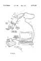
- FIG. 1is a perspective view of an automatic programmable hand-supportable laser bar code symbol reading device which may be used in conjunction with system and method of the present invention
- FIG. 2is a cross-sectional elevated side view along the longitudinal extent of the automatic bar code symbol reading device of FIG. 1, showing various hardware and software components used in realizing the same;
- FIG. 2Ais a cross-sectional plan view along the longitudinal extent of the automatic programmable bar code symbol reading device taken along line 2A--2A of FIG. 2, also showing the various components used in realizing the device;
- FIG. 3Ais an elevated side view of the programmable bar code reading device of the present invention, illustrating the spatial relationship between the object detection and scan fields of the device, and the programmable long and short ranges of programmed object detection and bar code presence detection;
- FIG. 3Bis a plan view of the automatic programmable bar code reading device taken along line 3A--3A of FIG. 3, also illustrating the spatial relationship between the object detection and scan fields of the device and the programmable long and short ranges of object and bar code presence detection;
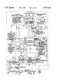
- FIG. 4is block functional system diagram of the automatic programmable bar code symbol reading device of FIG. 1, illustrating the principal components of the device integrated with the control system thereof;
- FIG. 5is a block functional diagram of a first embodiment of the object detection means of the automatic programmable bar code symbol reading device of the present invention
- FIG. 6is a block functional diagram of a second embodiment of the object detection means of the programmable bar code symbol reading device
- FIG. 7is a schematic representation of the memory structure of the function-parameter storage memory in the programmable bar code symbol reading device of FIG. 1;
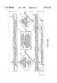
- FIG. 8is a block process diagram illustrating the major steps undertaken when carrying out the method of programming (i.e., configuring) a master set of system function parameters in a programmable bar code symbol reader according to a first illustrative embodiment of the present invention
- FIG. 9is a perspective view of the programmable bar code symbol reader of FIG. 1 operably connected to the function parameter acquisition system of the present invention, showing the function parameter reading system reading (i.e., acquiring) the "master" set of function parameters stored in the programmable bar code symbol reader and converting such function parameters directly into a printable list of function-encoded bar code symbols uniquely corresponding thereto, which when read in sequential order by another programmable bar code symbol reader, automatically programs the programmable bar code symbol reader with the master set of function parameters;
- the function parameter reading systemreading (i.e., acquiring) the "master" set of function parameters stored in the programmable bar code symbol reader and converting such function parameters directly into a printable list of function-encoded bar code symbols uniquely corresponding thereto, which when read in sequential order by another programmable bar code symbol reader, automatically programs the programmable bar code symbol reader with the master set of function parameters;
- FIG. 10is a schematic representation of an exemplary list of function-encoded bar code symbols printed in sequential order in accordance with the principles of the present invention.
- FIG. 10Ais a schematic representation of the format of each function-encoded bar code symbol printed in the exemplary master list of FIG. 10;
- FIG. 11is a schematic representation showing a programmable bar code symbol reader reading (i.e., scanning and decoding) the master list of function-encoded bar code symbols shown in FIG. 14;
- FIG. 12is a block process diagram illustrating the major steps undertaken when carrying out the method of programming a master set of system function parameters in a programmable bar code symbol reader according to a second illustrative embodiment of the present invention
- FIG. 13is a perspective view of a programmable bar code symbol reader of FIG. 1 operably connected to the function parameter reading system of the present invention, showing the function reading computer system reading (i.e., acquiring) the master set of function parameters stored in the programmable bar code symbol reader and converting such function parameters into a function-parameter programming file transmittable to a remotely situated computer system for printing out a master list of function-encoded bar code symbols uniquely corresponding thereto, and when read in sequential order by another programmable bar code symbol reader, automatically programs the bar code symbol reader with the master set of function parameters;
- the function reading computer systemreading (i.e., acquiring) the master set of function parameters stored in the programmable bar code symbol reader and converting such function parameters into a function-parameter programming file transmittable to a remotely situated computer system for printing out a master list of function-encoded bar code symbols uniquely corresponding thereto, and when read in sequential order by another programmable bar code symbol reader, automatically programs the bar code symbol reader with the master set of function parameters
- FIG. 14is a schematic representation of a master list of bar code symbol reading instructions referencing specific function-encoded bar code symbols preprinted in the bar code symbol programming booklet of FIG. 15, and when read in sequential order, automatically programs a bar code symbol reader with a particular master set of function parameters set in a master bar code symbol reader from which other bar code symbol scanners are to be configured;
- FIG. 15is a schematic representation of a preprinted bar code symbol programming guide constructed in accordance with the principles of the present invention.
- FIGS. 16A through 16Ctaken together, show a high level flow chart of a system control program (i.e., Main System Control Routine) illustrating various courses of programmed system operation that the automatic bar code symbol reading device may undergo during bar code symbol reading operations, as well as during function-parameter programming and acquisition operations; and
- a system control programi.e., Main System Control Routine
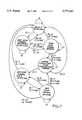
- FIG. 17is a state transition diagram showing the various state transitions that the programmable bar code symbol reading device of the present invention may undergo while in its bar code symbol reading mode.
- automatic bar code symbol reading system 1comprises an automatic hand-supportable bar code symbol reading device 2 operably associated with hand-supportable data collection device 3 of the present invention.
- Operable interconnection of bar code symbol reading device 2 and data collection device 3is achieved by a flexible multi-wire connector cord 4 extending from bar code symbol device 2 and plugged directly into the serial data-input communications port of the data collection device 3.
- RFRadio-Frequency
- automatic bar code symbol reading device 2comprises an ultra lightweight hand-supportable housing 5 having a head portion 5A that continuously extends into a contoured handle portion 5B at an obtuse deflection angle which can be in the range of 150 to about 170 degrees. In a preferred embodiment, deflection angle a is about 160 degrees.
- This ergonomic housing designis sculpted (i.e., form-fitted) to the hand, making scanning as easy and effortless as a wave of the hand.
- this featureeliminates risks of musculoskeletal disorders, such as carpal tunnel syndrome, which can result from repeated biomechanical stress commonly associated with pointing prior art gun-shaped scanners at a bar code, squeezing the trigger to activate the scanning beam, and then releasing the trigger.
- the head portion of housing 5has a transmission aperture 6 formed in upper portion of front panel 7, to permit desired optical radiation to exit and enter the housing, as will be described in detail hereinafter.
- the lower portion of front panel 7Bis optically opaque, as are all other surfaces of the hand-supportable housing.
- automatic bar code reading device 2generates two different fields external to the hand-supportable housing, in order to carry out automatic bar code symbol reading according to the principles of the present invention.
- an object detection fieldindicated by broken and dotted lines, is provided externally to the housing for detecting energy reflected off an object bearing a bar code, located within the object detection field.
- a scan fieldis provided external to the housing for scanning an object present within the scan field. Such scanning is achieved with a light beam so that scan data can be collected for detecting the presence of a bar code within the scan field, and for subsequently reading (i.e., scanning and decoding) the detected bar code symbol.
- the energy reflected of an object in the object detection fieldcan be optical radiation or acoustical energy, either sensible or non-sensible by the operator, and may be either generated by an external ambient source, or from the automatic bar code symbol reading device itself.
- this energyis a beam of infrared light projected forwardly from transmission aperture 6 in a spatially directed fashion, preferably essentially parallel to the longitudinal axis 8 of the head portion of the housing.
- the object detection fieldhas a three-dimensional volumetric expanse spatially coincident with the transmitted infrared light beam. This ensures that an object within the object detection field will be illuminated by the infrared light beam and that infrared light reflected therefrom will be directed generally towards the transmission aperture of the housing where it can be detected, to indicate that an object is within the object detection field.
- a light beamis automatically generated within the head portion of the housing and repeatedly scanned through the transmission aperture across the scan field. As illustrated in FIG. 1, at least a portion of the scanned light beam aligned with bar code on the detected object, will be reflected off the bar code and directed back towards and through the transmission aperture for collection, detection and subsequent processing in a manner which will be described in detail hereinafter.
- the object detection fieldis designed to spatially encompass at least a portion of the scan field along the operative scanning range of the device, as illustrated in FIGS. 3A and 3B.
- bar code symbol reading device of the first illustrated embodimentcomprises a number of system components, namely, an object detection circuit 9, scanning means 10, photoreceiving circuit 11, analog-to-digital (A/D) conversion circuit 12, bar code presence detection module 13, bar code scan range detection module 14, symbol decoding module 15, data format conversion module 16, symbol character data storage unit 17, function parameter storage memory (i.e., EPROM) 18, and serial data transceiver circuit 19.
- a magnetic field sensing circuit 20is provided for detecting housing support stand, while a manual switch 21 is provided for selecting long or short range modes of object and bar code presence detection.
- these componentsare operably associated with a programmable system controller 22 which provides a great degree of versatility in system control, capability and operation. The structure, function and advantages of this controller will be described in detail hereinafter.
- system controller 22bar code presence detection module 14, bar code scan range detection module 15, symbol decoding module 16, and data format conversion module 17 are realized using a single programmable device, such as a microprocessor having accessible program and buffer memory, and external timing means. It is understood, however, that any of these elements can be realized using separate discrete components as will be apparent to those skilled in the art.
- automatic bar code symbol reading device 2also includes power receiving lines 23 which lead to conventional power distribution circuitry (not shown) for providing requisite power to each of the system components, when and for time prescribed by the system controller.
- power receiving lines 23are provided within the encasing of flexible connector cord 4, run alongside data communication lines 24 of the device, and are thus physically associated with a multi-pin connector plug 25 at the end of the flexible connector cord.
- An on/off power switch or functionally equivalent devicemay be provided external the hand-supportable housing to permit the user to energize and de-energize the device.
- power delivered through the connector cord to the bar code symbol reading deviceis continuously provided to system controller 22 and object detection circuit 10 to continuously enable their operation, while only biasing voltages and the like are provided to all other system components. In this way, each remaining system component is initially deactivated (i.e., disabled) from operation and must be activated (i.e., enabled) by the system controller.
- flexible connector cord 4can be eliminated replaced by RF signal transmission circuitry and a miniature internally disposed power supply as described therein.
- the purpose of the object detection circuitis to determine (i.e., detect) the presence of an object (e.g., product, document, etc.) within the object detection field of bar code symbol reading device 2, and in response thereto, automatically produce first control activation signal A 1 .
- first control activation signal A 1is provided as input to the system controller which, as will be described in greater detail hereinafter, causes the device to undergo a transition to the bar code symbol presence detection state.
- FIGS. 5A and 5Btwo different approaches to detecting the presence of an object within the object detection field are disclosed.
- an "active" object detection circuit 10Ais shown. In essence, this circuit operates by transmitting an infrared (IR) light signal forwardly into the object detection field.
- First control activation signal A 1is generated upon receiving a reflection of the transmitted signal off an object within the object detection field.
- object detection circuit 10Ais realized as an IR sensing circuit which comprises a synchronous receiver/transmitter 27 and an infrared LED 28 that generates a 940 nanometer pulsed signal at a rate of 2.0 KHZ.
- This pulsed IR signalis transmitted through focusing lens 29 to illuminate the object detection field.
- a reflected pulse signalis produced and focused through focusing lens 30 onto photodiode 31.
- the light collecting (i.e., optical) characteristics of focusing lens 30 and aperturewill essentially determine the geometric characteristics of the object detection field. Consequently, the optical characteristics of lens 30 and aperture will be selected to provide an object detection field which spatially encompasses at least a portion of the scanning field along the operative scanning range of the device.
- first control activation signal A 11
- a passive object detection circuit 10Bis shown. In essence this circuit operates by passively detecting ambient light within the object detection field. First control activation signal A 1 is generated upon receiving light of different intensity reflected off an object within the object detection field.
- object detection circuit 10Bis realized as a passive ambient light detection circuit which comprises a pair of photodiodes 35 and 36, that sense ambient light gathered from two spatially overlapping parts of the object detection field using focusing lenses 37 and 38, respectively.
- the optical characteristics of focusing lenses 37 and 38will essentially determine the geometric characteristics of the object detection field. Consequently, the optical characteristics of these lenses will be selected to provide an object detection field which spatially encompasses at least a portion of the scanning field along the operative scanning range of the device.
- the output signals of photodiodes 35 and 36are converted to voltages by current-to-voltage amplifiers 39 and 40 respectively, and are provided as input to a differential amplifier 41.
- the output of differential amplifier 41is provided as input to a sample and hold amplifier 42 in order to reject 60 and 120 Hz noise.
- Output signal of amplifier 42is provided as input to a logarithmic amplifier 43 to compand signal swing.
- the output signal of logarithmic amplifier 43is provided as input to a differentiator 44 and then to a comparator 45.
- the output of comparator 45provides first control activation signal A 1 .
- object detection circuit 10is realized as an ultrasonic energy sensing mechanism.
- ultrasonic energyis generated and transmitted forwardly of the housing head portion into the object detection field.
- ultrasonic energy reflected off an object within the object detection fieldis detected closely adjacent the transmission window using an ultrasonic energy detector.
- a focusing elementis disposed in front of the detector in order to effectively maximize collection of reflected ultrasonic energy.
- the focusing elementwill essentially determine the geometrical characteristics of the object detection field of the device. Consequently, as with the other above-described object detection circuits, the energy focusing (i.e., collecting) characteristics of the focusing element will be selected to provide an object detection field which spatially encompasses at least a portion of the scan field.
- the IR sensing circuiti.e., object detection means
- the long range specification for object detectionis preselected to be the full or entire range of sensitivity provided by IR sensing circuit 10A (e.g., 0 to about 10 inches), which is schematically indicated in FIGS. 3A and 3B.
- the short range of object detectionis about 0 to about 3 inches or so, as schematically indicated in FIGS. 3 and 3A, to provide CCD-like scanner emulation.
- the inherently limited depth of field and width of field associated with the short range mode of object detectionprevents, in essence, the scanning means 11 from flooding the scan field with laser scanning light and inadvertently detecting undesired bar code symbols.
- object detection range selectionis described in great detail in U.S. Pat. No. 5,340,971.
- scanning means 11comprises a light source 47 which, in general, may be any source of intense light (e.g., laser light) suitably selected for maximizing the reflectively from the object's surface bearing the bar code symbol.
- light source 47comprises a solid-state visible laser diode (VLD) which is driven by a conventional driver circuit 48.
- VLDvisible laser diode
- the wavelength of visible laser light produced from laser diode 47is about 670 nanometers.
- a planar scanning mirror 49can be oscillated back and forth by a stepper motor 50 driven by a conventional driver circuit 51, as shown.
- a stepper motor 50driven by a conventional driver circuit 51, as shown.
- one of a variety of conventional scanning mechanismsmay be alternatively used with excellent results.
- the system controllerprovides laser diode enable signal E L and scanning motor enable signal E M as input to driver circuits 48 and 51, respectively.
- E Mis a logical high level the laser beam is scanned through the transmission aperture and across the scan field.
- Photoreceiving circuit 12is provided for the purpose of detecting at least a portion of laser light of variable intensity, which is reflected off the object and bar code symbol within the scan field. Upon detection of this scan data signal, photoreceiving circuit 12 produces an analog scan data signal D 1 indicative of the detected light intensity.
- photoreceiving circuit 12comprises scan data collection mirror 53 which focuses received optical scan data signals for subsequent detection by a photoreceiver 54 having, mounted in front of its sensor, a wavelength selective filter 150 which only transmits optical radiation of wavelengths up to a small band above 670 nanometers.
- Photoreceiver 54in turn, produces an analog signal which is subsequently amplified by preamplifier 55 to produce analog scan data signal D 1 .
- scanning means 11 and photoreceiving circuit 12cooperate to generate scan data signals from the scan field, over time intervals specified by the system controller. As will illustrated hereinafter, these scan data signals are used by bar code presence detection module 14, bar code scan range detection module 15 and symbol decoding module 16.
- analog scan data signal D 1is provided as input to A/D conversion circuit 13.
- A/D conversion circuit 13processes analog scan data signal D 1 to provide a digital scan data signal D 2 which resembles, in form, a pulse width modulated signal, where logical "1" signal levels represent spaces of the scanned bar code and logical "0" signal levels represent bars of the scanned bar code.
- A/D conversion circuit 13can be realized by any conventional A/D chip. Digitized scan data signal D 2 is provided as input to bar code presence detection module 14, bar code scan range detection module 15 and symbol decoding module 16.
- bar code presence detection module 14is realized as a microcode program carried out by the microprocessor and associated program and buffer memory, described hereinbefore.
- the function of the bar code presence detection moduleis not to carry out a decoding process but rather to simply and rapidly determine whether the received scan data signals produced during bar code presence detection, represent a bar code symbol residing within the scan field. There are many ways in which to achieve this through a programming implementation.
- the aim of bar code presence detection module 14is to simply detect a bar code symbol "envelope". This is achieved by first processing a digital scan data signal D 2 so as to produce digitized "count” data and digital "sign" data.
- the digital count datais representative of the measured time interval (i.e., duration) of each signal level between detected signal level transitions which occur in digitized scan data signal D 2 .
- the digital sign dataindicates whether the signal level between detected signal level transitions is either a logical "1", representative of a space, or a logical "0", representative of a bar within a bar code symbol.
- the bar code presence detection moduleuses the digital count and sign data, the bar code presence detection module then determines in a straightforward manner whether or not the envelope of a bar code symbol is represented by the collected scan data.
- long range specification for bar code presence detectionis preselected to be the entire operative scanning range available to the device. In an illustrated embodiment, this range can be from about 0 to about 10 inches from the transmission aperture, depending on the optics employed in the scanning means. This range is schematically indicated in FIGS. 3A and 3B.
- short range specification for bar code presence detectionis preselected to be the same range selected for short range object detection (e.g. approximately 0 to about 3 inches from the transmission aperture), as indicated in FIGS. 3 and 3A.
- the inherently limited depth of field and width of field associated with the short range mode of bar code symbol detectionprevents scanning means 11 and bar code symbol detection module 14 from actuating the reading of undesired bar code symbols in the scan field.
- the purpose and function of the bar code scan range detection moduleis not to detect the presence of a bar code symbol in the scan field, but rather to determine the range that a detected bar code symbol resides from the transmission aperture of the bar code symbol reading device.
- This data processing moduleoperates upon digitized scan data signal D 2 collected from a bar code symbol which has been previously detected by the bar code symbol presence detection module.
- symbol decoding module 16The function of symbol decoding module 16 is to process, scan line by scan line, the stream of digitized scan data D 2 , in an attempt to decode a valid bar code symbol within a predetermined time period allowed by the system controller.
- symbol character data D 3(typically in ASCII code format) is produced corresponding to the decoded bar code symbol.
- a third control activation signal A 3is automatically produced by the symbol decoding module and is provided to the system controller in order to perform its system control functions.
- the system controllergenerates and provides enable signals E FC , E DS and E DT to data format conversion module 17, data storage unit 18 and serial data transceiver circuit 19, respectively, at particular stages of its control program.
- symbol decoding module 16provides symbol character data D 3 to data format module 17 to convert data D 3 into two differently formatted types of symbol character data, namely D 4 and D 5 .
- Format-converted symbol character data D 4is of the "packed data" format, particularly adapted for efficient storage in data storage unit 18.
- Format-converted symbol character data D 5is particularly adapted for data transmission to data collection and storage device 3, or a host device such as, a computer or electronic cash register.
- symbol character data D 4When symbol character data D 4 is to be converted into the format of the user's choice (based on a selected option mode), the system controller will generate and provide enable signal E DS to data storage unit 18, as shown in FIG. 4. Similarly, when format converted data D 5 is to be transmitted to a host device, the system controller will generate and provide enable signal E DT to data transmission circuit 19. Thereupon, data transmission circuit 19 transmits format-converted symbol character data D 5 to data collection device 3, via the data transmission lines of flexible connector cable 4.
- bar code symbol reading device 2In order to select either the long or short range mode of object (and/or bar code symbol presence) detection, bar code symbol reading device 2 is provided with both manual and automated mechanisms for effectuating such selections.
- a manual switche.g., step button 21 is mounted onto the top surface of the handle portion of the housing, so that long and short range modes of object detection can be simply selected by depressing this switch with ones thumb while handling the bar code reading device.
- the switchgenerates and provides mode activation signal A 4 to the system controller, which in turn generates the appropriate mode enable signal E IRT .
- housing support stand detection means 20is operably associated with the system controller to automatically generate mode activation signal A 4 , when the hand-supportable housing is not, for example, being supported within a housing support stand (not shown) which bears a permanent magnetic disposed in proximity with its housing support surfaces.
- a visual indicator lightis provided to the housing to visually indicate the particular mode which has been manually or automatically selected.
- magnetic sensing circuit 20comprises a magnetic flux detector 60, a preamplifier and a threshold detection circuit.
- Magnetic flux detector 60produces as output an electrical signal representative of the intensity of detected magnetic flux density in its proximity.
- housing 5When housing 5 is placed in housing support stand embodying a permanent magnet(not shown), magnetic flux detector 60 will be in position to detect flux emanating from the permanent magnet.
- magnetic flux detector 60is mounted to the rearward underside surface of the handle portion of the housing.
- a ferrous bar 61is interiorly mounted to the underside surface of the housing handle portion as shown.
- This arrangementfacilitates releasable magnetic attachment of the hand-supportable housing to the magnetic bar fixedly installed in a housing support stand of the type described above.
- a hole 62is drilled through ferrous bar 61 to permit installation of magnetic flux detector 60 so that magnetic flux emanating from the magnetic bar in the support stand is detectable when the housing is positioned within the housing support stand.
- FIGS. 2 and 2Aone preferred arrangement is illustrated.
- FIG. 2Athe optical arrangement of the system components is shown. Specifically, visible laser diode 47 is mounted in the rear corner of circuit board 64 installed within the head portion of the housing.
- a stationary concave mirror 53is mounted centrally at the front end of circuit board 63, primarily for collecting laser light. Notably, the height of concave mirror 53 is such as not to block light transmission aperture 6.
- Mounted off center onto the surface of concave mirror 53is very small second mirror 64 for directing the laser beam to planar mirror 49 which is connected to the motor shaft of a scanning motor 50, for joint oscillatory movement therewith.
- scanning motor 50is mounted centrally at the rear end of circuit board 63.
- photodetector 54is mounted in the opposite rear corner of circuit board 63.
- laser diode 47 adjacent the rear of the head portionproduces and directs a laser beam in a forward direction to the small stationary mirror 64 and is reflected back to oscillating mirror 49.
- Oscillating mirror 49scans the laser beam over the scan field.
- the returning light beam, reflected from the bar codeis directed back to oscillating mirror 49, which also acts as a collecting mirror.
- This oscillating mirrorthen directs the beam to stationary concave mirror 53 at the forward end of the housing head portion.
- the beam reflected from the concave mirror 53is directed to photodetector 54 to produce an electrical signal representative of the intensity of the reflected light.
- IR LED 28 and photodiode 31are mounted to circuit board 63, in a slightly offset manner from longitudinal axis 9 of the head portion of the housing.
- Apertures 65 and 66are formed in opaque portion 7B of the housing below the transmission aperture, to permit transmission and reception of IR type object sensing energy, as hereinbefore described.
- a metallic optical tube 67 having an aperture 68encases photodiode 31.
- a plastic filter lens 69is installed over the transmission aperture for transmitting only optical radiation from slightly below 670 nanometers.
- the combination of filter lens 69 at the transmission aperture and wavelength selective filter 150 before photoreceiver 54cooperate to form a narrow band-pass optical filter having a center wavelength of about 670 nanometers. This arrangement provides improved signal-to-noise ratio for detected scan data signals D 1 .
- the automatic bar code symbol reading device described abovehas numerous programmable system functions that can be selected (i.e., programmed) by simply entering its Function-Programming Mode, and then reading specific function-encoded bar code symbols that correspond to particular system functions that one wants programmably implemented.
- the purpose of function parameter storage memory 19is to store parametric data representative of particular functions that have been programmably selected while the device was in the Function-Programming Mode.
- each function parameteris assigned a unique memory address 19A, and is grouped into a function class indicated in FIG. 7 by reference numeral 19B. In general, within each function class, one or more function parameters may be selected.
- the function parameter storage memory 19stores function parameters for the following set of function classes: decode functions 19C; supplemental functions 19D; ITF symbol lengths 19E; minimum symbol length 19F; symbol length lock 19G; communication mode selection 19H; beeper operating characteristics 19I; scanner definition and test modes and same symbol time-out 19J; scanner functionality features 19K; UPC formatting options 19L; Non-UPC formatting options 19M; and long-range/short range selections 19N; etc.
- one or more function parameters in storage memory 19are set during the Function-Programming Mode of the bar code symbol reader of the illustrative embodiment.
- the bar code symbol reader hereofmay be programmed into any one of typically tens of thousands of different possible Function Configuration States.
- Function Configuration Statesthere is one Default Function Configuration State, in which each function parameter within each function class is set to a prespecified (i.e., default) parameter value.
- the bar code symbol readeroperates in a predetermined manner.
- Any desired Function Configuration Statecan be programmably selected by first causing the bar code symbol reader to first enter its Function Programming Mode.
- this programming modeis entered whenever a user desires to program (i.e., select) functions in the bar code symbol reader for either mastering or cloning a bar code symbol scanner/reader.
- one or more function parameters in any single Function Classcan then be individually set by reading one or more corresponding function-encoded bar code symbols off a preprinted Bar Code Symbol Programming Guide.
- the preprinted Bar Code Symbol Programming Guideis of the general type distributed by Metrologic Instruments, Inc. with each one of its programmable bar code symbol scanners and readers.
- the first step in the method of FIG. 8involves connecting a local function-parameter reading (i.e., acquisition) computer system 70 to "master" bar code symbol reader.
- function parameter reading computer system 70is realized as a laptop computer system running either MS-DOS, Microsoft Windows, X-Windows, or Macintosh System 7.5 Operating System software.
- the computer systemhas a high-resolution local printer 71 and printer drivers for printing bar code symbols in a manner well known in the art.
- the function-parameter reading computer system 70has stored on its hard-drive memory, a Function Parameter Configuration Program which is particularly designed to cooperate with the Main System Control Routine of each master bar code symbol reader. The functions of the Function Configuration Program will be described in great detail hereinafter with reference to FIGS. 8 and 12.
- the master bar code symbol reader 2is connected to the function-parameter reading computer system 70 by connecting the serial data communication port of the master bar code symbol reader to the serial data communication port of the function-parameter reading computer system 70.
- a conventional serial data communication cable 73is used to achieve such a connection.
- the function parameter reading computer system 70reads the function parameters from the function parameter storage memory 19 of the master bar code symbol reader 2, and buffers these parameters within its memory.
- the function-parameter reading computer system 70running the Function Parameter Configuration Program, uses the buffered function parameters to create an (ASCII-based) Function Parameter Configuration File.
- Function Parameter Programming Filecomprises a list of ASCII codes whose first list entry is representative of Function Programming Mode Activation, and whose last list entry is representative of Function Programming Mode Deactivation.
- the second list entryis an ASCII code which represents the setting of all function parameters to the predetermined Default Parameter Settings.
- the third to the second-to-last list entriesare ASCII codes representative of function parameters of the master bar code symbol reader, arranged in a predetermined order between the first and last list entries of this list-type file structure.
- the function parameter reading computer system 70then locally converts the Function Parameter Programming File Structure into a Bar Code Symbol (BCS) Encoded Function Parameter Programming File Structure.
- the BCS-Encoded Function Parameter Programming Filerepresents a list of Function-Encoded Bar Code Symbols which, when read in sequence by a clone bar code symbol reader 2', automatically programs the function parameters in clone bar code symbol reader 2' to that of the master bar code symbol reader 2.
- each ASCII code in the Function Parameter Programming Fileis assigned a unique bar code symbol (e.g., typically representative of a unique number) and the digital code associated with the assigned bar code symbol is placed in the BCS-Encoded Function Parameter Programming File.
- the BCS-Encoded Function Parameter Programming Fileis provided to local printer 71, its processor can decode such digital codes and properly print the bar code symbol assigned to each list entry in the Function Parameter Programming File.
- the local function parameter reading computer system 70uses the BCS-Encoded Function Parameter Programming File to produce a bar code symbol list 75.
- bar code symbol list 75is particularly encoded to programmably configure a compatible bar code symbol reader 2 with the same function parameters set in master bar code symbol reader 2.
- a compatible (i.e., like) bar code symbol reader 2'is configured into the master bar code symbol reader 2, by reading, in sequential order, the list of bar code symbols 75 custom-printed by the local printer 71.
- each bar code symbol printed in the third through the second-to-last position in the list 75has three fields, namely: Memory Address Field 76; Function Parameter Value Field 77; and Set/Clear Field 78.
- the Memory Address Field 77indicates the address location in function parameters storage 19 where the function parameter data is stored.
- the Function Parameter Valve Field 78identifies the value of the function parameter to be set.
- the Set/Clear Field 79indicates the particular operation that is to be performed on the parameter stored in the addressed memory storage location. The binary bits in each of these fields are decoded by system controller 22 shown in FIG. 4.
- the first bar code symbol 80 in the printed list 75is read by clone bar code symbol reader 2' as shown in FIG. 11, it automatically causes (i.e., induces) bar code symbol reader 2' being configured to enter its Function-Programming Mode of Operation.
- the second bar code symbol (i.e., the "Recall Default Function Parameters" bar code symbol) 81 in the printed listis read, it automatically causes all the function parameters to be set to their Default values, thus providing a memory reference. This memory reference is used when particular function parameters are changed during whenever the third bar code symbol 82 through the second-from-last bar code symbol 83 are read from the printed list 75.
- the bar code symbol reader 2'When all of the steps in FIG. 8 are completed, the bar code symbol reader 2', which has read the printed list of bar code symbols 75 in sequential order, will be automatically programmed with the identical configuration of function parameters set in the master bar code symbol reader 2'. As such, the clone bar code symbol scanner 2' will have the same configuration of functionalities as the master bar code symbol reader 2.
- FIG. 12the method of the second illustrative embodiment present invention is shown carried out using the function reading computer system 70 of FIG. 9, with several modifications.
- a printer 89remotely located from "local" function parameter reading computer system 70, is operably associated with a remote computer system 90.
- Local and remote computer systems 70 and 90are in data communication with each other by way of a pair of modems 91 and 92, which may be either external or internal to its respective computer system.
- Each of these modemsin turn are connected to a data combination network 93 of one sort of another.
- the data communication networkcan be a public switching telecommunications network, local area network (LAN), wide area network (WAN), or any other communication medium over which serial or parallel data communication can be performed.
- Blocks A through D of FIG. 12are identical to Block A through D of FIG. 8.
- the BCS-Encoded Function Parameter Programming Fileis transmitted from local function parameter reading computer system 70 to the remote computer system 90 by way of modems 91 and 92 and communication network 93.
- the received BCS-Encoded Function Parameter Programming Fileis stored in memory within computer system 90.
- the remote computer system 90uses the stored BCS-Encoded Function Parameter Programming File to print a list of Bar Code Symbol Reading Instructions 95 which contains a list of codes for printing a specific list of Bar Code Symbol Reading Instructions.
- Each Bar Code Symbol Reading Instruction in this custom listspecifies a specific function-encoded bar code symbol, referenced and preprinted in a Bar Code Symbol Programming Booklet 96 of the type shown in FIG. 15, which is read in a particular order during function parameter configuration process.
- each Bar Code Symbol Reading Instruction 97has a Page Reference and Function-Encoded Symbol reference.
- the Page Referencemakes a reference to a particular page in the Bar Code Symbol Programming Booklet 96, whereas Function-encoded Symbol reference refers to a function-encoded bar code symbol printed on the referenced page in the BCS-Programming Booklet.
- each pagealso includes printed bar code symbols 80 and 84 for entering and exiting the Function Parameter Programming Mode, respectively, of the programming bar code symbol reader 2' being configured.
- the Bar Code Symbol Reading Instruction List 95is read in the specified order, so as to automatically configure the function parameters of the bar code symbol reader 2' to have identically the same system function configuration as the master bar code symbol reader 2.
- This last step, at Block G,is carried out as follows. First, the user must first the read bar code symbol specified by the first bar code symbol reading instruction 97, which causes the symbol reading device to enter its Function Parameter Programming Mode of operation. Secondly, the user must then the read bar code symbol specified by the second bar code symbol reading instruction 98, which causes all of the function parameters in the symbol reading device to be set to their Default values. Thereafter, the third instruction 99, forth and subsequent instructions are followed in order to automatically program the function parameters specified thereby.
- the last bar code symbol, referenced by instruction 100is read in order to cause the bar code symbol reader to exit the Function Programming Mode and return to its normal Symbol Reading Mode.
- the bar code symbol reading deviceis initialized. This involves continuously activating (i.e., enabling) IR sensing circuit 10A and the system controller.
- a preset time periode.g., 0 ⁇ T 1 , ⁇ 3 seconds
- Block Hthis represents a state from the bar code presence detection state to the bar code symbol reading state. Proceeding to block H, the system controller continues activation of laser diode 47, scanning motor 50, photoreceiving circuit 12, and A/D conversion circuit 13, and commences activation of symbol decoding module 14. At this stage, fresh bar code scan data is collected and is subject to decode processing. At essentially the same time, at Block I, the system controller starts timer T 3 to run for a time period 0 ⁇ T 3 ⁇ 1 second.
- this eventcauses a transition from the bar code reading state to the object detection state.
- the system controllerreturns to Block A, as shown.
- control activation signal A 31 from symbol decoding module 16, indicative that a bar code symbol has been successfully read
- the system controllerproceeds to Block 0 in FIG. 16B.
- the system controllerdetermines whether the read bar code symbol is preassigned (i.e., pre-encoded) to activate the Function Parameter Reading Mode of the bar code symbol reading device. Typically, such a bar code symbol will be read by the "master" bar code symbol reader 2 as illustrated in FIGS. 9 and 13.
- the system controllerdetermines whether the serial data communication port of the bar code symbol reading device (i.e., serving as a "master” symbol reader) is operably connected to the serial data communication port of the function-parameter reading computer system 70. In the illustrative embodiment, this connection is achieved by way of data communication cable 73. If such connection or communication link is not established at this stage of the process, then at Block P the system controller returns to Block A in FIG. 16A, as shown. If, however, these devices are operably linked for data communication, then at Block Q the system controller in master bar code symbol reading device 2 enters its Function Parameter Reading Mode.
- the system controllerreads the function parameters set in its function parameter memory 19, and then transmits the read function parameters to the function-parameter reading computer system 70 operably connected to the data communication port of the master bar code symbol reader 2.
- the system controllerremains at Block S until all read function parameters have been successfully transmitted to function-parameter reading computer system 70.
- the received set of function parametersare then stored in the buffer memory within computer system 70, and subsequently processed and utilized as described above in connection with FIGS. 8 and 12, above.
- the system controller in master bar code symbol reader 2automatically exits its Function Parameter Reading Mode, returning to its normal Bar Code Symbol Reading Mode at Block A in 16A, as shown.
- the system controllerdetermines whether the read bar code symbol is the activation code symbol for the Function Parameter Reading Mode. If it is the activation code symbol for the Function Parameter Programming Mode, then at Block V the system controller enters the Function Parameter Programming Mode of the master bar code symbol reading device 2 and therefor automatically returns to Block A so that function-encoded read code symbols can be subsequently read during the "mastering" (i.e., function configuring process).
- the system controllerdetermines whether the read bar code symbol is the deactivation code symbol for deactivating the Function Parameter Programming Mode. If it is such a mode deactivation code symbol, then at Block X the system controller exits the Function Parameter Programming Mode and returns to Block A in FIG. 16A, as shown. If at Block W the read bar code symbol is not the deactivation code symbol for the Function Parameter Programming Mode, then at Block Y the system controller determines whether the Function Parameter Programming Mode is presently activated.
- the system controllerdetermines whether the read (i.e., scanned and decoded) bar code symbol is a function-encoded bar code symbol, such as the type 82-83 printed on list 75 shown in FIG. 11. If the read bar code symbol is a function-encoded bar code symbol, then at Block AA in FIG. 16B, the system controller (e.g., in the clone bar code symbol reader 2') decodes the bits in the fields of the function-encoded bar code symbol, sets the identified function parameter to the specified function parameter valve, and then returns to Block A in FIG. 16A, as shown. If, however, at Block Z, the system controller determines that the decode bar code symbol is not a function-encoded bar code symbol, then the system controller returns to the Block A in FIG. 16A, as shown.
- the system controllerdetermines that the decode bar code symbol is not a function-encoded bar code symbol, then the system controller returns to the Block A in FIG. 16A, as shown.
- Block Ythe system controller determines that the Function Programming Mode is not presently active, then the system controller proceeds to Block BB in FIG. 16C.
- the system controllercontinues to activate laser diode 47, scanning motor 50, photoreceiving circuit 12 and A/D conversion circuit 13, while deactivating symbol decoding module 16 and commencing activation of data format conversion module 17, data storage unit 18 and data transmission circuit 19.
- These operationsmaintain the scanning of the laser beam across the scan field, while symbol character data is appropriately formatted and transmitted to data collection device 3, or a host device, by a conventional data communication process well known in the art.
- the system controllerAfter transmission of symbol character data to the host device is completed, the system controller enters Block CC and continues activation of laser diode 47, scanning motor 50, photoreceiving circuit 12 and A/D conversion circuit 13, while deactivating symbol decoding module 16, data format-conversion module 18, data storage unit 18 and data transmission circuit 19.
- the system controllerproceeds through Blocks JJ and KK to reactivate the symbol decoding module and start timer T 6 to run for a time period 0 ⁇ T 6 ⁇ 1 second. These events represent a state transition from bar code symbol presence detection to bar code symbol reading.
- Block GGthe system controller determines at Block MM whether the decoded bar code symbol is different from the previously decoded bar code symbol. If it is different, then the system controller returns to Block BB as illustrated, to format and transmit symbol character data as described hereinabove.
- Block NN in FIG. 16Cthe system controller checks to determine whether timer T 4 has lapsed. If it has not lapsed, the system controller returns to Block GG to form a second loop, within which the device is permitted to detect or redetect a bar code symbol in the scan field and then successfully read a valid bar code symbol within the set time interval 0 ⁇ T 4 ⁇ 5 seconds. If, however, timer T 4 lapses, then the system controller proceeds to Block 00 at which the system controller deactivates laser diode 47, scanning motor 50, photoreceiving circuit 12, A/D conversion circuit 13, bar code presence detection module 14, and symbol decoding module 16.
- control activation signal A 10 is received from IR sensing circuit 10A, indicative that the object detection field is free of any objects.
- the system controllerreturns to the Block A, as shown in FIG. 8C.
- the bar code symbol reading device of the present inventionis capable of conditioning each of these states on whether the detected bar code symbol is present in either the long or short range portion of the scan field of the device. Additional details regarding the operation of the long and short range modes of the bar code symbol reading device hereof can be found in U.S. Pat. No. 5,340,971.
- FIG. 13provides a state transition diagram for the illustrative embodiment.
- the automatic bar code symbol reading device of the present inventionhas four basic states of operation namely: object detection, bar code symbol presence detection, bar code symbol reading, and symbol character data transmission/storage. The nature of each of these states have been described hereinabove in great detail. These four states are schematically illustrated as A, B, C and D, respectively, in the state transition diagram of FIG. 17. Notably, two "extensional states" have also been provided so that the automatic bar code reading devices of the illustrative embodiments are capable of reading an infinite number of consecutively different bar code symbols without returning to the object detection state. These states of operation are indicated as E and F and represent bar code presence detection and bar code symbol reading operations, respectively. As described above, these operations are employed when attempting to automatically read one or more consecutively different bar codes symbols, that is, after a first bar code symbol has been successfully read utilizing operation states A through C.
- transitions between the various statesare indicated by directional arrows, besides each of which are transition conditions expressed in terms of control activation signals (e.g., A 1 , A 2 and A 3 ), and where appropriate, state time intervals (e.g., T 1 , T 2 , T 3 , T 4 , T 5 and T 6 ).
- control activation signalse.g., A 1 , A 2 and A 3
- state time intervalse.g., T 1 , T 2 , T 3 , T 4 , T 5 and T 6 .
- the state diagram of FIG. 17expresses most simply the four basic and two extensional operations occurring during the control flow within the system control programs of FIGS. 16A-16C.
- the control activation signals A 1 , A 2 and A 3 in FIG. 17indicate which events within the object detection and/or scan fields can effect a state transition within the allotted time frame(s), where prescribed.
- the master and clone symbol reading devicesneed not be hand-supportable, nor automatic-type bar code symbol readers or scanners.
- the master and compatible clone symbol reading devicesmay be a programmable in-counter scanner; a programmable hand-held manually-trigger actuated scanner or reader; a programmable laser projection scanner; a programmable holographic scanner or reader; or the like.
- anyone of these bar code symbol scannersmay be fixed in position with respect to a support surface, such as a counter-top or work surface.
- the function parameter reading computer system of the present inventionneed not generate a list of function-encoded bar code symbols based on those listed in conventional programming manuals. Instead, the function parameter reading computer system may be programmed to generate a shorter list of function-encoded bar code symbols, than otherwise required when using bar code symbols listed in the conventional programming manual, while achieving equivalent results.
- This embodiment of the present inventionwill have the added advantage of minimizing the amount of paper and number of codes needed to clone a multitude of bar code symbol scanners.
- the function parameter reading computer system of the present inventionmay be programmed to read function parameters and create a facsimile list of function parameter encoded bar code symbols which are directly transmitted to a FAX machine located at a remote site not equipped with a conventional modem and bar code printing equipment.
- the function parameter computer system of the present inventioncan be programmed to generate a BCS-Encoded Function Parameter Programming File for direct transmission to either the host computer system (e.g., cash register) or "dumb" data terminal, to which the fixed position scanner is connected.
- host computer systeme.g., cash register
- umb data terminale.g., "dumb" data terminal
- POSPoint of Sale
- Compatible bar code symbol scannerscan then be programmed as "clones" of the master scanner by simply reading the list of printed bar code symbols.
- bar and space type code symbol scannershave been described in the illustrative embodiments, it is understood that the present invention may be practiced using other types of code symbols, such as 2-D codes that do not employ bars and spaces, such as UPC codes.
Landscapes
- Physics & Mathematics (AREA)
- Engineering & Computer Science (AREA)
- Electromagnetism (AREA)
- General Physics & Mathematics (AREA)
- Theoretical Computer Science (AREA)
- General Health & Medical Sciences (AREA)
- Artificial Intelligence (AREA)
- Computer Vision & Pattern Recognition (AREA)
- Toxicology (AREA)
- Health & Medical Sciences (AREA)
- General Engineering & Computer Science (AREA)
- Optics & Photonics (AREA)
- Programmable Controllers (AREA)
- Cash Registers Or Receiving Machines (AREA)
Abstract
Description
Claims (5)
Priority Applications (4)
| Application Number | Priority Date | Filing Date | Title |
|---|---|---|---|
| US08/697,154US5777315A (en) | 1991-09-17 | 1996-08-21 | Method and apparatus for programming system function parameters in programmable code symbol readers |
| US09/481,798US6321989B1 (en) | 1991-09-17 | 1998-07-06 | Method and apparatus for programming system function parameters in programmable code symbol readers |
| US09/777,114US6347743B2 (en) | 1991-09-17 | 2001-02-05 | Method and apparatus for programming functional system parameters in optical bar code scanners |
| US09/967,421US6565005B1 (en) | 1991-09-17 | 2001-09-28 | Method and apparatus for programming functional system parameters in optical bar code scanners |
Applications Claiming Priority (7)
| Application Number | Priority Date | Filing Date | Title |
|---|---|---|---|
| US07/761,123US5340971A (en) | 1990-09-17 | 1991-09-17 | Automatic bar code reading system having selectable long range and short range modes of operation |
| US07/898,919US5340973A (en) | 1990-09-17 | 1992-06-12 | Automatic laser scanning system and method of reading bar code symbols using same |
| US08/292,237US5808285A (en) | 1990-09-17 | 1994-08-17 | Portable code symbol reading device with one-way wireless data packet transmission link to base unit employing condition-dependent acoustical signalling for data packet reception acknowledgement |
| US29349294A | 1994-08-19 | 1994-08-19 | |
| US08/293,695US5468951A (en) | 1990-09-17 | 1994-08-19 | Automatic hand-supportable code symbol scanning device with improved laser beam pointing efficiency |
| US38932095A | 1995-02-16 | 1995-02-16 | |
| US08/697,154US5777315A (en) | 1991-09-17 | 1996-08-21 | Method and apparatus for programming system function parameters in programmable code symbol readers |
Related Parent Applications (2)
| Application Number | Title | Priority Date | Filing Date |
|---|---|---|---|
| US08/293,695Continuation-In-PartUS5468951A (en) | 1990-09-10 | 1994-08-19 | Automatic hand-supportable code symbol scanning device with improved laser beam pointing efficiency |
| US38932095AContinuation | 1991-09-17 | 1995-02-16 |
Related Child Applications (1)
| Application Number | Title | Priority Date | Filing Date |
|---|---|---|---|
| US09/481,798ContinuationUS6321989B1 (en) | 1991-09-17 | 1998-07-06 | Method and apparatus for programming system function parameters in programmable code symbol readers |
Publications (1)
| Publication Number | Publication Date |
|---|---|
| US5777315Atrue US5777315A (en) | 1998-07-07 |
Family
ID=27559614
Family Applications (4)
| Application Number | Title | Priority Date | Filing Date |
|---|---|---|---|
| US08/697,154Expired - LifetimeUS5777315A (en) | 1991-09-17 | 1996-08-21 | Method and apparatus for programming system function parameters in programmable code symbol readers |
| US09/481,798Expired - Fee RelatedUS6321989B1 (en) | 1991-09-17 | 1998-07-06 | Method and apparatus for programming system function parameters in programmable code symbol readers |
| US09/777,114Expired - Fee RelatedUS6347743B2 (en) | 1991-09-17 | 2001-02-05 | Method and apparatus for programming functional system parameters in optical bar code scanners |
| US09/967,421Expired - Fee RelatedUS6565005B1 (en) | 1991-09-17 | 2001-09-28 | Method and apparatus for programming functional system parameters in optical bar code scanners |
Family Applications After (3)
| Application Number | Title | Priority Date | Filing Date |
|---|---|---|---|
| US09/481,798Expired - Fee RelatedUS6321989B1 (en) | 1991-09-17 | 1998-07-06 | Method and apparatus for programming system function parameters in programmable code symbol readers |
| US09/777,114Expired - Fee RelatedUS6347743B2 (en) | 1991-09-17 | 2001-02-05 | Method and apparatus for programming functional system parameters in optical bar code scanners |
| US09/967,421Expired - Fee RelatedUS6565005B1 (en) | 1991-09-17 | 2001-09-28 | Method and apparatus for programming functional system parameters in optical bar code scanners |
Country Status (1)
| Country | Link |
|---|---|
| US (4) | US5777315A (en) |
Cited By (50)
| Publication number | Priority date | Publication date | Assignee | Title |
|---|---|---|---|---|
| US5914474A (en)* | 1996-04-29 | 1999-06-22 | Webscan, Inc. | Methods of calibrating bar code evaluation systems |
| EP1026626A1 (en)* | 1999-02-02 | 2000-08-09 | Sony Corporation | Mobile electronic information apparatus |
| US6129796A (en)* | 1994-12-06 | 2000-10-10 | Winchester-Auburn Mills, Inc. | Apparatus and method for dispensing and labeling cord |
| US6325283B1 (en)* | 2000-10-25 | 2001-12-04 | Soy Chu | Computer implemented program for inventory management |
| US6347743B2 (en)* | 1991-09-17 | 2002-02-19 | Metrologic Instruments, Inc. | Method and apparatus for programming functional system parameters in optical bar code scanners |
| US6349879B1 (en)* | 1999-02-02 | 2002-02-26 | Fujitsu Limited | POS system, an optical reader, and an information processing system |
| US6357659B1 (en)* | 1999-06-03 | 2002-03-19 | Psc Scanning, Inc. | Hands free optical scanner trigger |
| US20020171745A1 (en)* | 2001-05-15 | 2002-11-21 | Welch Allyn Data Collection, Inc. | Multimode image capturing and decoding optical reader |
| US6484937B1 (en)* | 1997-02-14 | 2002-11-26 | Oberthur Card Systems Sa | Method for storing data in a chip card rewritable memory |
| US20030085284A1 (en)* | 2000-02-28 | 2003-05-08 | Psc Scanning, Inc. | Multi-format bar code reader |
| US20030098352A1 (en)* | 2000-11-24 | 2003-05-29 | Metrologic Instruments, Inc. | Handheld imaging device employing planar light illumination and linear imaging with image-based velocity detection and aspect ratio compensation |
| US20030156303A1 (en)* | 2001-11-21 | 2003-08-21 | Metrologic Instruments, Inc. | Planar light illumination and linear imaging (PLILIM) device with image-based velocity detection and aspect ratio compensation |
| US20040016812A1 (en)* | 1998-12-03 | 2004-01-29 | Metrologic Instruments, Inc. | Wireless bar code symbol reading system capable of automatically collecting and storing symbol character data when hand-supportable unit is operated outside of its RF data communication range, and automatically transmitting stored symbol character data when the hand-supportable unit is operated within its RF data communication range |
| US6776342B1 (en)* | 1997-07-29 | 2004-08-17 | Intermec Ip Corp. | Process for the parameterization of scanners for one-dimensional or two-dimensional printed codes |
| US20040173684A1 (en)* | 1998-12-03 | 2004-09-09 | Metrologic Instruments, Inc. | Automatically-activated hand-supportable omni-directional laser scanning bar code symbol reader having a user-selectable linear scanning menu-reading mode supported by a stroboscopically-pulsed omni-directional laser scanning pattern for improved bar code symbol navigation and alignment during menu-reading operations |
| US20040222300A1 (en)* | 2003-04-10 | 2004-11-11 | Strickland Stephen Scott | Method and system for automated setup of configuration parameters for a control processor |
| US20040258275A1 (en)* | 1999-05-19 | 2004-12-23 | Rhoads Geoffrey B. | Methods and systems for interacting with posters |
| US20050005102A1 (en)* | 2003-07-03 | 2005-01-06 | Meggitt Adam E. | Memory data copying system for devices |
| US20050082371A1 (en)* | 1998-12-03 | 2005-04-21 | Metrologic Instruments, Inc. | Automatically-activated wireless hand-supportable laser scanning bar code symbol reading system with data transmission activation switch and automatic communication range dependent control |
| US20050211782A1 (en)* | 1998-12-03 | 2005-09-29 | William Martin | Automatically-activated hand-supportable laser scanning bar code symbol reading system with omnidirectional and unidirectional scanning modes in addition to a data transmission activation switch |
| US20060000910A1 (en)* | 2004-06-30 | 2006-01-05 | Kelvin Chong | System and method for rapid deployment of a wireless device |
| US7059519B1 (en)* | 1999-06-17 | 2006-06-13 | Ier | Man/machine interface method and device for a ticket processing device comprising a magnetic stripe |
| US20070027964A1 (en)* | 2005-07-28 | 2007-02-01 | Allan Herrod | System and method for rapid deployment of network appliances and infrastructure devices |
| US20070119941A1 (en)* | 2005-11-30 | 2007-05-31 | Symbol Technologies, Inc. | Bar code scanner programming |
| US20070152056A1 (en)* | 2005-12-29 | 2007-07-05 | David Tuschel | Method and apparatus for counterfeiting protection |
| US20070152058A1 (en)* | 2006-01-05 | 2007-07-05 | Yeakley Daniel D | Data collection system having reconfigurable data collection terminal |
| WO2000028510A3 (en)* | 1998-11-12 | 2007-08-23 | Thomas Cies | Z-configuration structure for computers, scanners, and communications and video devices |
| US20080121711A1 (en)* | 2006-07-10 | 2008-05-29 | Blumer Larry L | Apparatus and Methods for Controlling an Imager |
| US20080121686A1 (en)* | 2006-11-08 | 2008-05-29 | Inventec Corporation | Input system and method |
| US20080283608A1 (en)* | 2003-11-13 | 2008-11-20 | Metrologic Instruments, Inc. | Method of illuminating objects on a countertop surface using an automatically-triggered digital image capture and processing system which maintains illumination rays substantially within the field of view (FOV) of said system, above which the field of view (FOV) of human operator and spectating customers are positioned |
| US20090001173A1 (en)* | 2007-06-28 | 2009-01-01 | Sevier Mitchel P | Bar code reading terminal with video capturing mode |
| US20090044003A1 (en)* | 2007-08-09 | 2009-02-12 | Hand Held Products, Inc. | Methods and apparatus to change a feature set on data collection devices |
| US20110095079A1 (en)* | 2009-10-26 | 2011-04-28 | Xerox Corporation | Method and apparatus for generating and using an options enablement sheet to activate options on an image production device |
| US20110102845A1 (en)* | 1999-06-30 | 2011-05-05 | Silverbrook Research Pty Ltd | Method of printing a copy of a previously printed document |
| US20110261203A1 (en)* | 2010-04-22 | 2011-10-27 | Hand Held Products, Inc. | Imaging scanner utilized as a cctv camera |
| US20120137348A1 (en)* | 2001-04-13 | 2012-05-31 | The Code Corporation | System and method for encoding and decoding data and references to data in machine-readable graphical codes |
| US20120138686A1 (en)* | 2010-12-01 | 2012-06-07 | Symbol Technologies, Inc. | Enhanced laser barcode scanning |
| US20120193426A1 (en)* | 2011-01-31 | 2012-08-02 | Metrologic Instruments, Inc. | Method, apparatus, and system for programming a barcode symbol scanning terminal with two-dimensional programming code |
| US20120250106A1 (en)* | 2011-03-30 | 2012-10-04 | Infosys Technologies Ltd. | Method, device and system for updating an application on a mobile device |
| US20130105569A1 (en)* | 2008-12-09 | 2013-05-02 | Felica Networks, Inc. | Information processing apparatus, information processing method, program and information processing system |
| US8517269B2 (en) | 2010-11-09 | 2013-08-27 | Hand Held Products, Inc. | Using a user'S application to configure user scanner |
| USD692431S1 (en)* | 2013-03-15 | 2013-10-29 | Rubbermaid Commercial Products Llc | Bar code scanner |
| US8608053B2 (en) | 2012-04-30 | 2013-12-17 | Honeywell International Inc. | Mobile communication terminal configured to display multi-symbol decodable indicia |
| US20140266589A1 (en)* | 2013-03-15 | 2014-09-18 | Overhead Door Corporation | Factory programming of paired authorization codes in wireless transmitter and door operator |
| US9143401B2 (en) | 2006-11-06 | 2015-09-22 | Ikan Holdings Llc | Methods and systems for network configuration |
| US9171193B1 (en)* | 2014-12-16 | 2015-10-27 | The Code Corporation | System and method for setting a real-time clock of a barcode reading device |
| EP2990990A1 (en)* | 2014-08-27 | 2016-03-02 | NCR Corporation | Automatic scanner configuration |
| US9311515B2 (en)* | 2014-08-29 | 2016-04-12 | Ncr Corporation | Automatic tuning of scanner lighting |
| EP1016953B1 (en)* | 1998-12-31 | 2019-07-24 | Xerox Corporation | Multi-level selection methods and apparatus using context identification |
| WO2019214398A1 (en)* | 2018-05-07 | 2019-11-14 | 腾讯科技(深圳)有限公司 | Methods and devices for displaying and scanning barcode, storage medium and electronic device |
Families Citing this family (36)
| Publication number | Priority date | Publication date | Assignee | Title |
|---|---|---|---|---|
| GB2282906B (en) | 1993-10-13 | 1996-11-06 | Dataquill Ltd | Data enty systems |
| US7387253B1 (en) | 1996-09-03 | 2008-06-17 | Hand Held Products, Inc. | Optical reader system comprising local host processor and optical reader |
| US20040004128A1 (en)* | 1996-09-03 | 2004-01-08 | Hand Held Products, Inc. | Optical reader system comprising digital conversion circuit |
| US6976626B2 (en)* | 1997-09-16 | 2005-12-20 | Metrologic Instruments, Inc. | Wireless bar code symbol driven portable data terminal (PDT) system adapted for single handed operation |
| US6745941B1 (en)* | 1999-06-21 | 2004-06-08 | Ge Interlogix, Inc. | Electronic key with optical scanner |
| US7708205B2 (en) | 2003-11-13 | 2010-05-04 | Metrologic Instruments, Inc. | Digital image capture and processing system employing multi-layer software-based system architecture permitting modification and/or extension of system features and functions by way of third party code plug-ins |
| US20020129259A1 (en)* | 2001-03-06 | 2002-09-12 | Chatterton Scott Johnson | System and method for accessing peripheral devices |
| US6676014B2 (en)* | 2001-03-31 | 2004-01-13 | Koninklijke Philips Electronics N.V. | Machine readable label system with offline capture and processing |
| US7055747B2 (en) | 2002-06-11 | 2006-06-06 | Hand Held Products, Inc. | Long range optical reader |
| US6959865B2 (en)* | 2002-03-28 | 2005-11-01 | Hand Held Products, Inc. | Customizable optical reader |
| US7219843B2 (en) | 2002-06-04 | 2007-05-22 | Hand Held Products, Inc. | Optical reader having a plurality of imaging modules |
| US20030222147A1 (en) | 2002-06-04 | 2003-12-04 | Hand Held Products, Inc. | Optical reader having a plurality of imaging modules |
| US7090132B2 (en) | 2002-06-11 | 2006-08-15 | Hand Held Products, Inc. | Long range optical reader |
| US8596542B2 (en) | 2002-06-04 | 2013-12-03 | Hand Held Products, Inc. | Apparatus operative for capture of image data |
| FR2849252A1 (en)* | 2002-12-19 | 2004-06-25 | Adhipress | Electronic lottery device, especially for use in supermarkets or similar, to enable winning of discount coupons or similar comprises a barcode reader and a coupon distributor |
| WO2004092993A1 (en)* | 2003-04-09 | 2004-10-28 | Gtech Rhode Island Corporation | Electronic payment system |
| US20050045635A1 (en)* | 2003-09-03 | 2005-03-03 | Jane Dong | Containers for storing articles |
| FR2867272B1 (en)* | 2004-03-06 | 2006-07-28 | Wilfrid Pierre Meffre | APPARATUS AND ASSOCIATED METHOD FOR MONITORING THE COLORIMETRIC QUALITY AND TRACEABILITY OF ANY DOCUMENT OR PRINTER OF ANY NATURE BY ANY USER HAVING THIS DOCUMENT |
| US8001550B2 (en)* | 2004-03-22 | 2011-08-16 | The Code Corporation | Object identifier readers that are configured to automatically send and/or store data read from an object identifier |
| US7273179B2 (en)* | 2004-07-09 | 2007-09-25 | Datalogic Scanning, Inc. | Portable data reading device with integrated web server for configuration and data extraction |
| US20110284625A1 (en) | 2005-12-16 | 2011-11-24 | Taylor Smith | Digital image capture and processing system supporting multiple third party code plug-ins with configuration files having conditional programming logic controlling the chaining of multiple third-party plug-ins |
| US8194254B2 (en)* | 2007-01-30 | 2012-06-05 | Hewlett-Packard Development Company, L.P. | Print device preconditioning |
| US7552863B2 (en)* | 2007-02-28 | 2009-06-30 | Hand Held Products, Inc. | Method for updating indicia readers |
| WO2008125997A1 (en)* | 2007-04-12 | 2008-10-23 | Koninklijke Philips Electronics, N.V. | Use of barcode menus to configure and set-up vital signs monitors |
| US8157176B2 (en)* | 2007-05-25 | 2012-04-17 | Hewlett-Packard Development Company, L.P. | Modular marking apparatus and method |
| US20090078774A1 (en)* | 2007-09-21 | 2009-03-26 | Symbol Technologies, Inc. | Graphical User Interface for Use in Programming a Barcode Reader |
| US20120168508A1 (en)* | 2010-12-30 | 2012-07-05 | Hand Held Products, Inc. | Indicia reading terminal having configurable operating characteristics |
| US8561903B2 (en) | 2011-01-31 | 2013-10-22 | Hand Held Products, Inc. | System operative to adaptively select an image sensor for decodable indicia reading |
| US8511572B2 (en) | 2011-08-31 | 2013-08-20 | Hand Held Products, Inc. | Encoded information reading terminal with data formatting functionality |
| US8608071B2 (en) | 2011-10-17 | 2013-12-17 | Honeywell Scanning And Mobility | Optical indicia reading terminal with two image sensors |
| US9092682B2 (en)* | 2012-05-25 | 2015-07-28 | Metrologic Instruments, Inc. | Laser scanning code symbol reading system employing programmable decode time-window filtering |
| US11110648B2 (en) | 2012-07-31 | 2021-09-07 | Makerbot Industries, Llc | Build material switching |
| US9070032B2 (en) | 2013-04-10 | 2015-06-30 | Hand Held Products, Inc. | Method of programming a symbol reading system |
| JP7194351B2 (en)* | 2018-09-26 | 2022-12-22 | ブラザー工業株式会社 | printer |
| US11803720B2 (en)* | 2022-01-28 | 2023-10-31 | Zebra Technologies Corporation | Methods and apparatus to determine barcode decoding parameters for a plurality of barcodes in an image |
| CN116578037B (en)* | 2023-07-10 | 2023-09-29 | 杭州鄂达精密机电科技有限公司 | Full inspection machine PLC control system and full inspection machine system |
Citations (11)
| Publication number | Priority date | Publication date | Assignee | Title |
|---|---|---|---|---|
| US4721849A (en)* | 1985-10-02 | 1988-01-26 | Videx, Inc. | Portable programmable optical code reader |
| US4825058A (en)* | 1986-10-14 | 1989-04-25 | Hewlett-Packard Company | Bar code reader configuration and control using a bar code menu to directly access memory |
| US4841132A (en)* | 1986-07-21 | 1989-06-20 | Matsushita Electric Industrial Co., Ltd. | Program recording scheduling apparatus using an optical reader |
| US4861972A (en)* | 1987-11-05 | 1989-08-29 | Spectra-Physics, Inc. | Bar code scanner and method of programming |
| US4866257A (en)* | 1987-11-19 | 1989-09-12 | Spectra-Physics, Inc. | Bar code scanner and method |
| US4868375A (en)* | 1988-08-22 | 1989-09-19 | Ncr Corporation | Method for changing the functions of a bar code reader |
| US5120943A (en)* | 1989-06-19 | 1992-06-09 | Wandel & Goltermann Gmbh & Co. | Method of and apparatus for setting a measuring instrument |
| US5185514A (en)* | 1991-09-19 | 1993-02-09 | Ncr Corporation | Programmable apparatus and method for optical scanners |
| US5214268A (en)* | 1991-08-15 | 1993-05-25 | Ncr Corporation | Apparatus for programming a bar code reader |
| US5256865A (en)* | 1991-11-05 | 1993-10-26 | Ncr Corporation | Automatic sensing and programming circuit and programming method for optical scanners |
| US5469291A (en)* | 1990-11-15 | 1995-11-21 | Gap Technologies, Inc. | Gyrating programmable scanner |
Family Cites Families (7)
| Publication number | Priority date | Publication date | Assignee | Title |
|---|---|---|---|---|
| CA2021519C (en)* | 1990-05-29 | 2001-09-04 | Jerome Swartz | Scanning system implemented on semiconductor or electro-optical substrate |
| US5340973A (en)* | 1990-09-17 | 1994-08-23 | Metrologic Instruments, Inc. | Automatic laser scanning system and method of reading bar code symbols using same |
| US5777315A (en)* | 1991-09-17 | 1998-07-07 | Metrologic Instruments, Inc. | Method and apparatus for programming system function parameters in programmable code symbol readers |
| FR2682396B1 (en)* | 1991-10-09 | 1995-01-06 | Pasteur Institut | NUCLEIC SEQUENCE OF THE GENE ASSOCIATED WITH KALLMANN SYNDROME LINKED TO CHROMOSOME X, CORRESPONDING PEPTIDE SEQUENCES; DIAGNOSTIC APPLICATIONS. |
| US5965863A (en)* | 1994-03-04 | 1999-10-12 | Welch Allyn, Inc. | Optical reader system comprising local host processor and optical reader |
| US5900613A (en)* | 1994-03-04 | 1999-05-04 | Welch Allyn, Inc. | Optical reader having improved reprogramming features |
| US20020079370A1 (en)* | 1998-03-11 | 2002-06-27 | Wood Robert J. | Illumination source for optical reading apparatus |
- 1996
- 1996-08-21USUS08/697,154patent/US5777315A/ennot_activeExpired - Lifetime
- 1998
- 1998-07-06USUS09/481,798patent/US6321989B1/ennot_activeExpired - Fee Related
- 2001
- 2001-02-05USUS09/777,114patent/US6347743B2/ennot_activeExpired - Fee Related
- 2001-09-28USUS09/967,421patent/US6565005B1/ennot_activeExpired - Fee Related
Patent Citations (13)
| Publication number | Priority date | Publication date | Assignee | Title |
|---|---|---|---|---|
| US4721849A (en)* | 1985-10-02 | 1988-01-26 | Videx, Inc. | Portable programmable optical code reader |
| US4841132A (en)* | 1986-07-21 | 1989-06-20 | Matsushita Electric Industrial Co., Ltd. | Program recording scheduling apparatus using an optical reader |
| US4825058A (en)* | 1986-10-14 | 1989-04-25 | Hewlett-Packard Company | Bar code reader configuration and control using a bar code menu to directly access memory |
| US4861972B1 (en)* | 1987-11-05 | 2000-12-05 | Spectra Physics Scanning Syst | Bar code scanner and method of programming |
| US4861972A (en)* | 1987-11-05 | 1989-08-29 | Spectra-Physics, Inc. | Bar code scanner and method of programming |
| US4866257A (en)* | 1987-11-19 | 1989-09-12 | Spectra-Physics, Inc. | Bar code scanner and method |
| US4866257C1 (en)* | 1987-11-19 | 2001-01-09 | Spectra Physics Scanning Syst | Bar code scanner and method |
| US4868375A (en)* | 1988-08-22 | 1989-09-19 | Ncr Corporation | Method for changing the functions of a bar code reader |
| US5120943A (en)* | 1989-06-19 | 1992-06-09 | Wandel & Goltermann Gmbh & Co. | Method of and apparatus for setting a measuring instrument |
| US5469291A (en)* | 1990-11-15 | 1995-11-21 | Gap Technologies, Inc. | Gyrating programmable scanner |
| US5214268A (en)* | 1991-08-15 | 1993-05-25 | Ncr Corporation | Apparatus for programming a bar code reader |
| US5185514A (en)* | 1991-09-19 | 1993-02-09 | Ncr Corporation | Programmable apparatus and method for optical scanners |
| US5256865A (en)* | 1991-11-05 | 1993-10-26 | Ncr Corporation | Automatic sensing and programming circuit and programming method for optical scanners |
Non-Patent Citations (1)
| Title |
|---|
| Intermec 9511 Online Reader, System Manual, Intermec Corporation, Dec. 1986.* |
Cited By (129)
| Publication number | Priority date | Publication date | Assignee | Title |
|---|---|---|---|---|
| US6565005B1 (en)* | 1991-09-17 | 2003-05-20 | Metrologic Instruments, Inc. | Method and apparatus for programming functional system parameters in optical bar code scanners |
| US6347743B2 (en)* | 1991-09-17 | 2002-02-19 | Metrologic Instruments, Inc. | Method and apparatus for programming functional system parameters in optical bar code scanners |
| US6129796A (en)* | 1994-12-06 | 2000-10-10 | Winchester-Auburn Mills, Inc. | Apparatus and method for dispensing and labeling cord |
| US5914474A (en)* | 1996-04-29 | 1999-06-22 | Webscan, Inc. | Methods of calibrating bar code evaluation systems |
| US6484937B1 (en)* | 1997-02-14 | 2002-11-26 | Oberthur Card Systems Sa | Method for storing data in a chip card rewritable memory |
| US6776342B1 (en)* | 1997-07-29 | 2004-08-17 | Intermec Ip Corp. | Process for the parameterization of scanners for one-dimensional or two-dimensional printed codes |
| WO2000028510A3 (en)* | 1998-11-12 | 2007-08-23 | Thomas Cies | Z-configuration structure for computers, scanners, and communications and video devices |
| US20050211782A1 (en)* | 1998-12-03 | 2005-09-29 | William Martin | Automatically-activated hand-supportable laser scanning bar code symbol reading system with omnidirectional and unidirectional scanning modes in addition to a data transmission activation switch |
| US20050199727A1 (en)* | 1998-12-03 | 2005-09-15 | Mark Schmidt | Wireless bar code symbol reading system capable of automatically collecting and storing symbol character data when hand-supportable unit is operated outside of its RF data communication range, and automatically transmitting stored symbol character data when the hand-supportable unit is operated within its RF data communication range |
| US7097105B2 (en) | 1998-12-03 | 2006-08-29 | Metrologic Instruments, Inc. | Automatically-activated hand-supportable omni-directional laser scanning bar code symbol reader having a user-selectable linear scanning menu-reading mode supported by a stroboscopically-pulsed omni-directional laser scanning pattern for improved bar code symbol navigation and alignment during menu-reading operations |
| US20060169782A1 (en)* | 1998-12-03 | 2006-08-03 | Metrologic Instruments, Inc. | Automatically-activated wireless laser scanning 2D bar code symbol reading system capable of automatically transmitting stored symbol character data when the hand-supportable unit is operated within its RF data communication range and automatically collecting and storing symbol character data when the hand-supportable unit is operated outside of its RF data communication range |
| US7137561B2 (en) | 1998-12-03 | 2006-11-21 | Metrologic Instruments, Inc. | Wireless laser scanning bar code symbol reading system employing a low-battery protection circuit, vibrational alarm and sleep mode of operation |
| US20080128512A1 (en)* | 1998-12-03 | 2008-06-05 | Metrologic Instruments, Inc. | Wireless hand-supportable code symbol reading system with automatic communication range dependent control |
| US7325740B2 (en) | 1998-12-03 | 2008-02-05 | Metrologic Instruments, Inc. | Automatically-activated laser scanning 2D bar code symbol reading system employing a visible linear-type laser scanning pattern and an audible feedback signal during scan data capturing and buffering operations |
| US7281663B2 (en) | 1998-12-03 | 2007-10-16 | Metrologic Instruments, Inc. | Wireless bar code symbol reading system having hand-supportable unit and remote base station |
| US7048192B2 (en) | 1998-12-03 | 2006-05-23 | Metrologic Instruments, Inc. | Wireless bar code symbol reading system employing a base station with a cradle having a hinged support hooks for enabling vertical and horizontal installations |
| US7028904B2 (en) | 1998-12-03 | 2006-04-18 | Metrologic Instruments, Inc. | Wireless bar code symbol reading system capable of automatically collecting and storing symbol character data when hand-supportable unit is operated outside of its rf data communication range, and automatically transmitting stored symbol character data when the hand-supportable unit is operated within its rf data communication range |
| US7278578B2 (en) | 1998-12-03 | 2007-10-09 | Metrologic Instruments, Inc. | Automatically-activated wireless laser scanning 2D bar code symbol reading system capable of automatically transmitting stored symbol character data when the hand-supportable unit is operated within its RF data communication range and automatically collecting and storing symbol character data when the hand-supportable unit is operated outside of its RF data communication range |
| US7111786B2 (en) | 1998-12-03 | 2006-09-26 | Metrologic Instruments, Inc. | Automatically-activated wireless hand-supportable laser scanning bar code symbol reading system with data transmission activation switch and automatic communication range dependent control |
| US20040173684A1 (en)* | 1998-12-03 | 2004-09-09 | Metrologic Instruments, Inc. | Automatically-activated hand-supportable omni-directional laser scanning bar code symbol reader having a user-selectable linear scanning menu-reading mode supported by a stroboscopically-pulsed omni-directional laser scanning pattern for improved bar code symbol navigation and alignment during menu-reading operations |
| US7007849B2 (en) | 1998-12-03 | 2006-03-07 | Metrologic Instruments, Inc. | Automatically-activated hand-supportable 2-d bar code symbol reading system employing a linear laser scanning pattern generator, an automatic bar code symbol data detector, audible data capture feedback generator, and a manually-activated data transmission activation switch |
| US7523867B2 (en) | 1998-12-03 | 2009-04-28 | Metrologic Instruments, Inc. | Automatically-activated hand-supportable laser scanning bar code symbol reading system with omnidirectional and unidirectional scanning modes in addition to a data transmission activation switch |
| US7686225B2 (en) | 1998-12-03 | 2010-03-30 | Metrologic Instruments, Inc. | Wireless code symbol reading system with automatic communication range dependent control |
| US20040016812A1 (en)* | 1998-12-03 | 2004-01-29 | Metrologic Instruments, Inc. | Wireless bar code symbol reading system capable of automatically collecting and storing symbol character data when hand-supportable unit is operated outside of its RF data communication range, and automatically transmitting stored symbol character data when the hand-supportable unit is operated within its RF data communication range |
| US7172126B2 (en) | 1998-12-03 | 2007-02-06 | Metrologic Instruments, Inc. | Wireless automatic laser scanning bar code symbol reading system, wherein the RF-based transceiver chipsets within the wireless hand-supportable unit and base station thereof are automatically deactivated and said RF data communication link therebetween terminated when said system enters its power-saving sleep mode, and reactivated and re-established when re-entering its operational mode |
| US20050082371A1 (en)* | 1998-12-03 | 2005-04-21 | Metrologic Instruments, Inc. | Automatically-activated wireless hand-supportable laser scanning bar code symbol reading system with data transmission activation switch and automatic communication range dependent control |
| US20050121523A1 (en)* | 1998-12-03 | 2005-06-09 | Metrologic Instruments, Inc. | Wireless laser scanning bar code symbol reading system employing a low-battery protection circuit, vibrational alarm and sleep mode of operation |
| US20050199726A1 (en)* | 1998-12-03 | 2005-09-15 | Metrologic Instruments, Inc. | Automatically-activated laser scanning 2D bar code symbol reading system |
| US20050199728A1 (en)* | 1998-12-03 | 2005-09-15 | Mark Schmidt | Wireless laser scanning bar code symbol reading system, wherein the RF-based transceiver chipsets within the wireless hand-supportable unit and base station thereof are automatically deactivated and said RF data communication link therebetween terminated when said system enters its power-saving sleep mode, and reactivated and re-eastablished when re-entering its operational mode |
| US20040251307A1 (en)* | 1998-12-03 | 2004-12-16 | Metrologic Instruments, Inc. | Automatically-activated hand-supportable 2-D bar code symbol reading system employing a linear laser scanning pattern generator, an automatic bar code symbol data detector, audible data capture feedback generator, and a manually-activated data transmission activation switch |
| US7464878B2 (en) | 1998-12-03 | 2008-12-16 | Metrologic Instruments, Inc. | Automatically-activated wireless hand-supportable laser scanning bar code symbol reading system with automatic communication range dependent control |
| US20050274810A1 (en)* | 1998-12-03 | 2005-12-15 | Metrologic Instruments, Inc. | Wireless bar code symbol reading system employing a base station with a cradle having a hinged support hooks for enabling vertical and horizontal installations |
| EP1016953B1 (en)* | 1998-12-31 | 2019-07-24 | Xerox Corporation | Multi-level selection methods and apparatus using context identification |
| EP1026621A3 (en)* | 1999-02-02 | 2002-08-14 | Fujitsu Limited | A point of sales system and an optical reader |
| EP1026626A1 (en)* | 1999-02-02 | 2000-08-09 | Sony Corporation | Mobile electronic information apparatus |
| US6520413B2 (en) | 1999-02-02 | 2003-02-18 | Fujitsu Limited | POS system, an optical reader, and an information processing system |
| US6349879B1 (en)* | 1999-02-02 | 2002-02-26 | Fujitsu Limited | POS system, an optical reader, and an information processing system |
| US20040258275A1 (en)* | 1999-05-19 | 2004-12-23 | Rhoads Geoffrey B. | Methods and systems for interacting with posters |
| US7377421B2 (en) | 1999-05-19 | 2008-05-27 | Digimarc Corporation | Methods and systems for interacting with printed articles, such as posters |
| EP1198778A4 (en)* | 1999-06-03 | 2004-03-31 | Psc Scanning Inc | FREELY OPERATED TRIGGER FOR AN OPTICAL SCANNER |
| US6357659B1 (en)* | 1999-06-03 | 2002-03-19 | Psc Scanning, Inc. | Hands free optical scanner trigger |
| US7059519B1 (en)* | 1999-06-17 | 2006-06-13 | Ier | Man/machine interface method and device for a ticket processing device comprising a magnetic stripe |
| US20110102845A1 (en)* | 1999-06-30 | 2011-05-05 | Silverbrook Research Pty Ltd | Method of printing a copy of a previously printed document |
| US20030085284A1 (en)* | 2000-02-28 | 2003-05-08 | Psc Scanning, Inc. | Multi-format bar code reader |
| US20070001014A1 (en)* | 2000-02-28 | 2007-01-04 | Psc Scanning, Inc. | Multi-format bar code reader |
| US7137555B2 (en) | 2000-02-28 | 2006-11-21 | Psc Scanning, Inc. | Multi-format bar code reader |
| US20080011856A1 (en)* | 2000-02-28 | 2008-01-17 | Datalogic Scanning, Inc. | Multi-format bar code reader |
| US7246747B2 (en) | 2000-02-28 | 2007-07-24 | Datalogic Scanning, Inc. | Multi-format bar code reader |
| US7527203B2 (en) | 2000-02-28 | 2009-05-05 | Datalogic Scanning, Inc. | Multi-format bar code reader |
| US6325283B1 (en)* | 2000-10-25 | 2001-12-04 | Soy Chu | Computer implemented program for inventory management |
| US20030098352A1 (en)* | 2000-11-24 | 2003-05-29 | Metrologic Instruments, Inc. | Handheld imaging device employing planar light illumination and linear imaging with image-based velocity detection and aspect ratio compensation |
| US8464930B2 (en)* | 2001-04-13 | 2013-06-18 | The Code Corporation | System and method for encoding and decoding data and references to data in machine-readable graphical codes |
| US20120137348A1 (en)* | 2001-04-13 | 2012-05-31 | The Code Corporation | System and method for encoding and decoding data and references to data in machine-readable graphical codes |
| US7543747B2 (en) | 2001-05-15 | 2009-06-09 | Hand Held Products, Inc. | Image capture apparatus and method |
| US7111787B2 (en) | 2001-05-15 | 2006-09-26 | Hand Held Products, Inc. | Multimode image capturing and decoding optical reader |
| US8794522B2 (en) | 2001-05-15 | 2014-08-05 | Hand Held Products, Inc. | Image capture apparatus and method |
| US20020171745A1 (en)* | 2001-05-15 | 2002-11-21 | Welch Allyn Data Collection, Inc. | Multimode image capturing and decoding optical reader |
| US8439262B2 (en) | 2001-05-15 | 2013-05-14 | Hand Held Products, Inc. | Image capture apparatus and method |
| US20030156303A1 (en)* | 2001-11-21 | 2003-08-21 | Metrologic Instruments, Inc. | Planar light illumination and linear imaging (PLILIM) device with image-based velocity detection and aspect ratio compensation |
| US7164810B2 (en) | 2001-11-21 | 2007-01-16 | Metrologic Instruments, Inc. | Planar light illumination and linear imaging (PLILIM) device with image-based velocity detection and aspect ratio compensation |
| US7668406B2 (en) | 2002-06-27 | 2010-02-23 | Metrologic Instruments, Inc. | Digital image acquisition system capable of compensating for changes in relative object velocity |
| US20080019615A1 (en)* | 2002-06-27 | 2008-01-24 | Schnee Michael D | Digital image acquisition system capable of compensating for changes in relative object velocity |
| EP1400915A3 (en)* | 2002-09-18 | 2004-04-14 | PSC Scanning, Inc. | Multi-format bar code reader |
| US7353995B2 (en)* | 2003-04-10 | 2008-04-08 | Siemens Energy & Automation, Inc. | Method and system for automated setup of configuration parameters for a control processor |
| US20040222300A1 (en)* | 2003-04-10 | 2004-11-11 | Strickland Stephen Scott | Method and system for automated setup of configuration parameters for a control processor |
| US20080203167A1 (en)* | 2003-07-03 | 2008-08-28 | Soule Robert M | Reprogramming system and method for devices including programming symbol |
| US8196832B2 (en) | 2003-07-03 | 2012-06-12 | Hand Held Products, Inc. | Reprogramming system and method for devices including programming symbol |
| US9262664B2 (en) | 2003-07-03 | 2016-02-16 | Hand Held Products, Inc. | Reprogramming system and method for devices including programming symbol |
| US8528821B2 (en) | 2003-07-03 | 2013-09-10 | Hand Held Products, Inc. | Reprogramming system and method for devices including programming symbol |
| US8985457B2 (en) | 2003-07-03 | 2015-03-24 | Hand Held Products, Inc. | Reprogramming system and method for devices including programming symbol |
| US20050005102A1 (en)* | 2003-07-03 | 2005-01-06 | Meggitt Adam E. | Memory data copying system for devices |
| US7367514B2 (en) | 2003-07-03 | 2008-05-06 | Hand Held Products, Inc. | Reprogramming system including reprogramming symbol |
| US7337317B2 (en) | 2003-07-03 | 2008-02-26 | Hand Held Products, Inc. | Memory data copying system for devices |
| US20050039092A1 (en)* | 2003-07-03 | 2005-02-17 | Soule Robert M. | Reprogramming system including reprogramming symbol |
| US9104930B2 (en) | 2003-11-13 | 2015-08-11 | Metrologic Instruments, Inc. | Code symbol reading system |
| US8317105B2 (en) | 2003-11-13 | 2012-11-27 | Metrologic Instruments, Inc. | Optical scanning system having an extended programming mode and method of unlocking restricted extended classes of features and functionalities embodied therewithin |
| US20080283608A1 (en)* | 2003-11-13 | 2008-11-20 | Metrologic Instruments, Inc. | Method of illuminating objects on a countertop surface using an automatically-triggered digital image capture and processing system which maintains illumination rays substantially within the field of view (FOV) of said system, above which the field of view (FOV) of human operator and spectating customers are positioned |
| US7980471B2 (en) | 2003-11-13 | 2011-07-19 | Metrologic Instruments, Inc. | Method of unlocking restricted extended classes of features and functionalities embodied within a digital image capture and processing system by reading feature/functionality-unlocking type code symbols |
| US8052057B2 (en) | 2003-11-13 | 2011-11-08 | Metrologic Instruments, Inc. | Method of programming the system configuration parameters of a digital image capture and processing system during the implementation of its communication interface with a host system without reading programming-type bar code symbols |
| US20060000910A1 (en)* | 2004-06-30 | 2006-01-05 | Kelvin Chong | System and method for rapid deployment of a wireless device |
| US7306153B2 (en)* | 2004-06-30 | 2007-12-11 | Symbol Technologies, Inc. | System and method for rapid deployment of a wireless device |
| US20070027964A1 (en)* | 2005-07-28 | 2007-02-01 | Allan Herrod | System and method for rapid deployment of network appliances and infrastructure devices |
| US20070119941A1 (en)* | 2005-11-30 | 2007-05-31 | Symbol Technologies, Inc. | Bar code scanner programming |
| US20070152056A1 (en)* | 2005-12-29 | 2007-07-05 | David Tuschel | Method and apparatus for counterfeiting protection |
| US9740905B2 (en) | 2006-01-05 | 2017-08-22 | Hand Held Products, Inc. | Data collection system having reconfigurable data collection terminal |
| US10223565B2 (en) | 2006-01-05 | 2019-03-05 | Hand Held Products, Inc. | Data collection system having reconfigurable data collection terminal |
| US20070152058A1 (en)* | 2006-01-05 | 2007-07-05 | Yeakley Daniel D | Data collection system having reconfigurable data collection terminal |
| US7934660B2 (en) | 2006-01-05 | 2011-05-03 | Hand Held Products, Inc. | Data collection system having reconfigurable data collection terminal |
| US9256772B2 (en) | 2006-01-05 | 2016-02-09 | Hand Held Products, Inc. | Data collection system having reconfigurable data collection terminal |
| US8851383B2 (en) | 2006-01-05 | 2014-10-07 | Hand Held Products, Inc. | Data collection system having reconfigurable data collection terminal |
| US20080121711A1 (en)* | 2006-07-10 | 2008-05-29 | Blumer Larry L | Apparatus and Methods for Controlling an Imager |
| US7798408B2 (en) | 2006-07-10 | 2010-09-21 | Hand Held Products, Inc. | Apparatus and methods for controlling an imager |
| US9979558B2 (en) | 2006-11-06 | 2018-05-22 | Ikan Holdings Llc | Methods and systems for network configuration |
| US9559858B2 (en) | 2006-11-06 | 2017-01-31 | Ikan Holdings Llc | Methods and systems for network configuration |
| US9143401B2 (en) | 2006-11-06 | 2015-09-22 | Ikan Holdings Llc | Methods and systems for network configuration |
| US10225097B2 (en) | 2006-11-06 | 2019-03-05 | Ikan Holdings Llc | Methods and systems for network configuration |
| US20080121686A1 (en)* | 2006-11-08 | 2008-05-29 | Inventec Corporation | Input system and method |
| US8496177B2 (en) | 2007-06-28 | 2013-07-30 | Hand Held Products, Inc. | Bar code reading terminal with video capturing mode |
| US20090001173A1 (en)* | 2007-06-28 | 2009-01-01 | Sevier Mitchel P | Bar code reading terminal with video capturing mode |
| US20090044003A1 (en)* | 2007-08-09 | 2009-02-12 | Hand Held Products, Inc. | Methods and apparatus to change a feature set on data collection devices |
| US8635309B2 (en) | 2007-08-09 | 2014-01-21 | Hand Held Products, Inc. | Methods and apparatus to change a feature set on data collection devices |
| US10242017B2 (en) | 2007-08-09 | 2019-03-26 | Hand Held Products, Inc. | Methods and apparatus to change a feature set on data collection devices |
| US8840026B2 (en)* | 2008-12-09 | 2014-09-23 | Felica Networks, Inc. | Information processing apparatus, information processing method, program and information processing system |
| US20130105569A1 (en)* | 2008-12-09 | 2013-05-02 | Felica Networks, Inc. | Information processing apparatus, information processing method, program and information processing system |
| US20110095079A1 (en)* | 2009-10-26 | 2011-04-28 | Xerox Corporation | Method and apparatus for generating and using an options enablement sheet to activate options on an image production device |
| US8418913B2 (en)* | 2009-10-26 | 2013-04-16 | Xerox Corporation | Method and apparatus for generating and using an options enablement sheet to activate options on an image production device |
| US20110261203A1 (en)* | 2010-04-22 | 2011-10-27 | Hand Held Products, Inc. | Imaging scanner utilized as a cctv camera |
| US8944327B2 (en) | 2010-11-09 | 2015-02-03 | Hand Held Products, Inc. | Using a user's application to configure user scanner |
| US8517269B2 (en) | 2010-11-09 | 2013-08-27 | Hand Held Products, Inc. | Using a user'S application to configure user scanner |
| US8579198B2 (en)* | 2010-12-01 | 2013-11-12 | Symbol Technologies, Inc. | Enhanced laser barcode scanning |
| US20120138686A1 (en)* | 2010-12-01 | 2012-06-07 | Symbol Technologies, Inc. | Enhanced laser barcode scanning |
| US20120193426A1 (en)* | 2011-01-31 | 2012-08-02 | Metrologic Instruments, Inc. | Method, apparatus, and system for programming a barcode symbol scanning terminal with two-dimensional programming code |
| US8302865B2 (en)* | 2011-01-31 | 2012-11-06 | Metrologic Instruments, Inc. | Method, apparatus, and system for programming a barcode symbol scanning terminal with two-dimensional programming code |
| US20120250106A1 (en)* | 2011-03-30 | 2012-10-04 | Infosys Technologies Ltd. | Method, device and system for updating an application on a mobile device |
| US8608053B2 (en) | 2012-04-30 | 2013-12-17 | Honeywell International Inc. | Mobile communication terminal configured to display multi-symbol decodable indicia |
| US9316038B2 (en)* | 2013-03-15 | 2016-04-19 | Overhead Door Corporation | Factory programming of paired authorization codes in wireless transmitter and door operator |
| US9869120B2 (en) | 2013-03-15 | 2018-01-16 | Overhead Door Corporation | Programming of paired authorization codes in wireless transmitter and barrier operator prior to use by end user |
| USD692431S1 (en)* | 2013-03-15 | 2013-10-29 | Rubbermaid Commercial Products Llc | Bar code scanner |
| US20140266589A1 (en)* | 2013-03-15 | 2014-09-18 | Overhead Door Corporation | Factory programming of paired authorization codes in wireless transmitter and door operator |
| US20160063285A1 (en)* | 2014-08-27 | 2016-03-03 | Ncr Corporation | Automatic scanner configuration |
| US10769389B2 (en)* | 2014-08-27 | 2020-09-08 | Ncr Corporation | Automatic scanner configuration |
| CN105389601B (en)* | 2014-08-27 | 2019-01-18 | Ncr公司 | Autoscanner configuration |
| EP2990990A1 (en)* | 2014-08-27 | 2016-03-02 | NCR Corporation | Automatic scanner configuration |
| US9311515B2 (en)* | 2014-08-29 | 2016-04-12 | Ncr Corporation | Automatic tuning of scanner lighting |
| US9171193B1 (en)* | 2014-12-16 | 2015-10-27 | The Code Corporation | System and method for setting a real-time clock of a barcode reading device |
| US9418268B2 (en)* | 2014-12-16 | 2016-08-16 | The Code Corporation | System and method for setting a real-time clock of a barcode reading device |
| WO2019214398A1 (en)* | 2018-05-07 | 2019-11-14 | 腾讯科技(深圳)有限公司 | Methods and devices for displaying and scanning barcode, storage medium and electronic device |
| US11347954B2 (en) | 2018-05-07 | 2022-05-31 | Tencent Technology (Shenzhen) Company Limited | Bar code generation scanning, and display method, apparatus, storage medium, and electronic device |
| US11620469B2 (en) | 2018-05-07 | 2023-04-04 | Tencent Technology (Shenzhen) Company Limited | Bar code generation scanning, and display method, apparatus, storage medium, and electronic device |
Also Published As
| Publication number | Publication date |
|---|---|
| US6565005B1 (en) | 2003-05-20 |
| US6321989B1 (en) | 2001-11-27 |
| US20010007334A1 (en) | 2001-07-12 |
| US6347743B2 (en) | 2002-02-19 |
Similar Documents
| Publication | Publication Date | Title |
|---|---|---|
| US5777315A (en) | Method and apparatus for programming system function parameters in programmable code symbol readers | |
| US6976632B2 (en) | Automatic hand-supportable laser scanner and method of reading bar code symbols using same | |
| US5789730A (en) | Automatic hand-supportable laser scanner and method of reading bar code symbols using same | |
| EP1457916B1 (en) | Automatically-activated hand-supportable laser scanning bar code reading system having data-transmission activation switch | |
| US5468951A (en) | Automatic hand-supportable code symbol scanning device with improved laser beam pointing efficiency | |
| US7077327B1 (en) | System for reading bar code symbols using bar code readers having RF signal transmission links with base stations | |
| US6575369B1 (en) | Automatic optical projection scanner with improved activation controlling mechanism | |
| US5883375A (en) | Bar code symbol scanner having fixed and hand-held modes | |
| US5484992A (en) | Automatic hand-supportable laser scanner with flickering laser scanning beam to improve visibility thereof and beam-symbol alignment during bar code symbol presence detection | |
| US5627359A (en) | Laser code symbol scanner employing optical filtering system having narrow band-pass characteristics and spatially separated optical filter elements with laser light collection optics arranged along laser light return path disposed therebetween | |
| US6860427B1 (en) | Automatic optical projection scanner for omni-directional reading of bar code symbols within a confined scanning volume | |
| US6182898B1 (en) | Bar code scanner with intuitive head aiming and collimated scan volume | |
| US5942743A (en) | Portable automatic hand-supportable omnidirectional laser projection scanner with power conserving control system | |
| US6286760B1 (en) | Automatic hand-supportable laser projection scanner for omni-directional reading of bar code symbols within a narrowly confined scanning volume | |
| US6604684B1 (en) | Automatic optical projection scanner for omni-directional reading of bar code symbols within a confined scanning volume |
Legal Events
| Date | Code | Title | Description |
|---|---|---|---|
| STCF | Information on status: patent grant | Free format text:PATENTED CASE | |
| FEPP | Fee payment procedure | Free format text:PAYOR NUMBER ASSIGNED (ORIGINAL EVENT CODE: ASPN); ENTITY STATUS OF PATENT OWNER: LARGE ENTITY | |
| AS | Assignment | Owner name:PNC BANK, NATIONAL ASSOCIATION, PENNSYLVANIA Free format text:SECURITY AGREEMENT;ASSIGNORS:METROLOGIC INSTRUMENTS, INC.;ADAPTIVE OPTICS ASSOCIATES, INC.;REEL/FRAME:011511/0142 Effective date:20010108 | |
| FEPP | Fee payment procedure | Free format text:PAT HOLDER NO LONGER CLAIMS SMALL ENTITY STATUS, ENTITY STATUS SET TO UNDISCOUNTED (ORIGINAL EVENT CODE: STOL); ENTITY STATUS OF PATENT OWNER: LARGE ENTITY | |
| REFU | Refund | Free format text:REFUND - PAYMENT OF MAINTENANCE FEE, 4TH YR, SMALL ENTITY (ORIGINAL EVENT CODE: R283); ENTITY STATUS OF PATENT OWNER: LARGE ENTITY | |
| FPAY | Fee payment | Year of fee payment:4 | |
| FEPP | Fee payment procedure | Free format text:PAYOR NUMBER ASSIGNED (ORIGINAL EVENT CODE: ASPN); ENTITY STATUS OF PATENT OWNER: LARGE ENTITY Free format text:PAYER NUMBER DE-ASSIGNED (ORIGINAL EVENT CODE: RMPN); ENTITY STATUS OF PATENT OWNER: LARGE ENTITY | |
| AS | Assignment | Owner name:METROLOGIC INSTRUMENTS, INC., NEW JERSEY Free format text:RELEASE OF SECURITY INTEREST;ASSIGNOR:PNC BANK, NATIONAL ASSOCIATION;REEL/FRAME:016026/0789 Effective date:20041026 | |
| FPAY | Fee payment | Year of fee payment:8 | |
| AS | Assignment | Owner name:MORGAN STANLEY & CO. INCORPORATED, NEW YORK Free format text:FIRST LIEN IP SECURITY AGREEMENT;ASSIGNORS:METROLOGIC INSTRUMENTS, INC.;METEOR HOLDING CORP.;OMNIPLANAR, INC.;REEL/FRAME:018942/0315 Effective date:20061221 Owner name:MORGAN STANLEY & CO. INCORPORATED, NEW YORK Free format text:SECOND LIEN IP SECURITY AGREEMENT;ASSIGNORS:METROLOGIC INSTRUMENTS, INC.;METEOR HOLDING CORP.;OMNIPLANAR, INC.;REEL/FRAME:018942/0671 Effective date:20061221 Owner name:MORGAN STANLEY & CO. INCORPORATED,NEW YORK Free format text:FIRST LIEN IP SECURITY AGREEMENT;ASSIGNORS:METROLOGIC INSTRUMENTS, INC.;METEOR HOLDING CORP.;OMNIPLANAR, INC.;REEL/FRAME:018942/0315 Effective date:20061221 Owner name:MORGAN STANLEY & CO. INCORPORATED,NEW YORK Free format text:SECOND LIEN IP SECURITY AGREEMENT;ASSIGNORS:METROLOGIC INSTRUMENTS, INC.;METEOR HOLDING CORP.;OMNIPLANAR, INC.;REEL/FRAME:018942/0671 Effective date:20061221 | |
| AS | Assignment | Owner name:METROLOGIC INSTRUMENTS, INC., NEW JERSEY Free format text:FIRST LIEN INTELLECTUAL PROPERTY SECURITY AGREEMENT RELEASE;ASSIGNOR:MORGAN STANLEY & CO. INCORPORATED;REEL/FRAME:023085/0754 Effective date:20080701 Owner name:METEOR HOLDING CORPORATION, NEW JERSEY Free format text:FIRST LIEN INTELLECTUAL PROPERTY SECURITY AGREEMENT RELEASE;ASSIGNOR:MORGAN STANLEY & CO. INCORPORATED;REEL/FRAME:023085/0754 Effective date:20080701 Owner name:OMNIPLANAR, INC., NEW JERSEY Free format text:FIRST LIEN INTELLECTUAL PROPERTY SECURITY AGREEMENT RELEASE;ASSIGNOR:MORGAN STANLEY & CO. INCORPORATED;REEL/FRAME:023085/0754 Effective date:20080701 Owner name:METROLOGIC INSTRUMENTS, INC., NEW JERSEY Free format text:SECOND LIEN INTELLECTUAL PROPERTY SECURITY AGREEMENT RELEASE;ASSIGNOR:MORGAN STANLEY & CO. INCORPORATED;REEL/FRAME:023085/0809 Effective date:20080701 Owner name:METEOR HOLDING CORPORATION, NEW JERSEY Free format text:SECOND LIEN INTELLECTUAL PROPERTY SECURITY AGREEMENT RELEASE;ASSIGNOR:MORGAN STANLEY & CO. INCORPORATED;REEL/FRAME:023085/0809 Effective date:20080701 Owner name:OMNIPLANAR, INC., NEW JERSEY Free format text:SECOND LIEN INTELLECTUAL PROPERTY SECURITY AGREEMENT RELEASE;ASSIGNOR:MORGAN STANLEY & CO. INCORPORATED;REEL/FRAME:023085/0809 Effective date:20080701 Owner name:METROLOGIC INSTRUMENTS, INC.,NEW JERSEY Free format text:FIRST LIEN INTELLECTUAL PROPERTY SECURITY AGREEMENT RELEASE;ASSIGNOR:MORGAN STANLEY & CO. INCORPORATED;REEL/FRAME:023085/0754 Effective date:20080701 Owner name:METEOR HOLDING CORPORATION,NEW JERSEY Free format text:FIRST LIEN INTELLECTUAL PROPERTY SECURITY AGREEMENT RELEASE;ASSIGNOR:MORGAN STANLEY & CO. INCORPORATED;REEL/FRAME:023085/0754 Effective date:20080701 Owner name:OMNIPLANAR, INC.,NEW JERSEY Free format text:FIRST LIEN INTELLECTUAL PROPERTY SECURITY AGREEMENT RELEASE;ASSIGNOR:MORGAN STANLEY & CO. INCORPORATED;REEL/FRAME:023085/0754 Effective date:20080701 Owner name:METROLOGIC INSTRUMENTS, INC.,NEW JERSEY Free format text:SECOND LIEN INTELLECTUAL PROPERTY SECURITY AGREEMENT RELEASE;ASSIGNOR:MORGAN STANLEY & CO. INCORPORATED;REEL/FRAME:023085/0809 Effective date:20080701 Owner name:METEOR HOLDING CORPORATION,NEW JERSEY Free format text:SECOND LIEN INTELLECTUAL PROPERTY SECURITY AGREEMENT RELEASE;ASSIGNOR:MORGAN STANLEY & CO. INCORPORATED;REEL/FRAME:023085/0809 Effective date:20080701 Owner name:OMNIPLANAR, INC.,NEW JERSEY Free format text:SECOND LIEN INTELLECTUAL PROPERTY SECURITY AGREEMENT RELEASE;ASSIGNOR:MORGAN STANLEY & CO. INCORPORATED;REEL/FRAME:023085/0809 Effective date:20080701 | |
| FPAY | Fee payment | Year of fee payment:12 |