US5777229A - Sensor transport system for combination flash butt welder - Google Patents
Sensor transport system for combination flash butt welderDownload PDFInfo
- Publication number
- US5777229A US5777229AUS08/668,957US66895796AUS5777229AUS 5777229 AUS5777229 AUS 5777229AUS 66895796 AUS66895796 AUS 66895796AUS 5777229 AUS5777229 AUS 5777229A
- Authority
- US
- United States
- Prior art keywords
- emat
- weld
- sheet metal
- control unit
- transport apparatus
- Prior art date
- Legal status (The legal status is an assumption and is not a legal conclusion. Google has not performed a legal analysis and makes no representation as to the accuracy of the status listed.)
- Expired - Fee Related
Links
- 238000003466weldingMethods0.000claimsabstractdescription27
- 238000007689inspectionMethods0.000claimsabstractdescription18
- 238000004891communicationMethods0.000claimsabstractdescription10
- 238000003708edge detectionMethods0.000claimsabstractdescription10
- 239000002184metalSubstances0.000claimsdescription41
- 238000000034methodMethods0.000claimsdescription16
- 230000007547defectEffects0.000claimsdescription6
- 238000012360testing methodMethods0.000abstractdescription10
- 230000001066destructive effectEffects0.000abstractdescription7
- 238000004519manufacturing processMethods0.000description6
- 238000005096rolling processMethods0.000description3
- 238000010008shearingMethods0.000description3
- 239000000463materialSubstances0.000description2
- 238000009659non-destructive testingMethods0.000description2
- 230000002411adverseEffects0.000description1
- 230000004888barrier functionEffects0.000description1
- 230000001934delayEffects0.000description1
- 230000002939deleterious effectEffects0.000description1
- 230000001419dependent effectEffects0.000description1
- 238000001514detection methodMethods0.000description1
- 238000001035dryingMethods0.000description1
- 230000000694effectsEffects0.000description1
- 230000008030eliminationEffects0.000description1
- 238000003379elimination reactionMethods0.000description1
- 238000011156evaluationMethods0.000description1
- 230000003116impacting effectEffects0.000description1
- 230000010354integrationEffects0.000description1
- 238000005259measurementMethods0.000description1
- 238000005554picklingMethods0.000description1
- 238000012545processingMethods0.000description1
- 238000012552reviewMethods0.000description1
- 230000035945sensitivityEffects0.000description1
- 230000000007visual effectEffects0.000description1
- 238000012800visualizationMethods0.000description1
- XLYOFNOQVPJJNP-UHFFFAOYSA-NwaterSubstancesOXLYOFNOQVPJJNP-UHFFFAOYSA-N0.000description1
Images

Classifications
- G—PHYSICS
- G01—MEASURING; TESTING
- G01N—INVESTIGATING OR ANALYSING MATERIALS BY DETERMINING THEIR CHEMICAL OR PHYSICAL PROPERTIES
- G01N29/00—Investigating or analysing materials by the use of ultrasonic, sonic or infrasonic waves; Visualisation of the interior of objects by transmitting ultrasonic or sonic waves through the object
- G01N29/22—Details, e.g. general constructional or apparatus details
- G01N29/24—Probes
- G01N29/2412—Probes using the magnetostrictive properties of the material to be examined, e.g. electromagnetic acoustic transducers [EMAT]
- G—PHYSICS
- G01—MEASURING; TESTING
- G01N—INVESTIGATING OR ANALYSING MATERIALS BY DETERMINING THEIR CHEMICAL OR PHYSICAL PROPERTIES
- G01N29/00—Investigating or analysing materials by the use of ultrasonic, sonic or infrasonic waves; Visualisation of the interior of objects by transmitting ultrasonic or sonic waves through the object
- G01N29/22—Details, e.g. general constructional or apparatus details
- G01N29/26—Arrangements for orientation or scanning by relative movement of the head and the sensor
- G01N29/265—Arrangements for orientation or scanning by relative movement of the head and the sensor by moving the sensor relative to a stationary material
- G—PHYSICS
- G01—MEASURING; TESTING
- G01N—INVESTIGATING OR ANALYSING MATERIALS BY DETERMINING THEIR CHEMICAL OR PHYSICAL PROPERTIES
- G01N2291/00—Indexing codes associated with group G01N29/00
- G01N2291/04—Wave modes and trajectories
- G01N2291/042—Wave modes
- G01N2291/0422—Shear waves, transverse waves, horizontally polarised waves
- G—PHYSICS
- G01—MEASURING; TESTING
- G01N—INVESTIGATING OR ANALYSING MATERIALS BY DETERMINING THEIR CHEMICAL OR PHYSICAL PROPERTIES
- G01N2291/00—Indexing codes associated with group G01N29/00
- G01N2291/04—Wave modes and trajectories
- G01N2291/042—Wave modes
- G01N2291/0425—Parallel to the surface, e.g. creep waves
- G—PHYSICS
- G01—MEASURING; TESTING
- G01N—INVESTIGATING OR ANALYSING MATERIALS BY DETERMINING THEIR CHEMICAL OR PHYSICAL PROPERTIES
- G01N2291/00—Indexing codes associated with group G01N29/00
- G01N2291/04—Wave modes and trajectories
- G01N2291/044—Internal reflections (echoes), e.g. on walls or defects
- G—PHYSICS
- G01—MEASURING; TESTING
- G01N—INVESTIGATING OR ANALYSING MATERIALS BY DETERMINING THEIR CHEMICAL OR PHYSICAL PROPERTIES
- G01N2291/00—Indexing codes associated with group G01N29/00
- G01N2291/10—Number of transducers
- G01N2291/102—Number of transducers one emitter, one receiver
- G—PHYSICS
- G01—MEASURING; TESTING
- G01N—INVESTIGATING OR ANALYSING MATERIALS BY DETERMINING THEIR CHEMICAL OR PHYSICAL PROPERTIES
- G01N2291/00—Indexing codes associated with group G01N29/00
- G01N2291/26—Scanned objects
- G01N2291/267—Welds
Definitions
- the present inventionrelates in general to an automated system for non-destructive inspection of a weld through the use of ultrasonic waves, and specifically, to a sensor transport system for a combination flash butt welder.
- An inspection devicethat uses ultrasonic waves to non-destructively test the welds shortly after they have been made.
- the deviceemploys Electromagnetic Acoustic Transducers (EMAT) which are arranged to transmit and receive what are known to be SH shear waves.
- EMATElectromagnetic Acoustic Transducers
- the SH shear wavesare launched by a transmitter meander coil EMAT, and the waves travel through the sheet metal to the weld where they are reflected back through the sheet metal and are received by a separate receiver meander coil EMAT located near the transmitter.
- the reflected waveproduces an electrical signal in the receiver coil, which is monitored while both the transmitter coil and the receiver coil are scanned close to the surface of the sheet metal, parallel to the weld line, and over the full width of the sheet metal. During the scanning, the amplitude of the signal produced in the receiver coil is measured and used to indicate the quality of the weld.
- the known deviceis retrofitted into a flash butt welding machine on a production line, and a motorized transport apparatus into which the transmitter and receiver coils are mounted is used to carry out each weld scan.
- operation of the known devicerequires full-time control by a human operator, who, through the manipulation of push buttons, moves and positions the transport apparatus with the transmitter and receiver coils onto and across the sheet metal surface subsequent to the making of each weld by the welding machine.
- Results of the testi.e., the measured amplitude of the receiver coil signal, are recorded on a device such as a strip chart recorder and are monitored by the human operator.
- the present inventionhas among its principal novel features the ability to automatically sense the completion of the welding process, immediately thereafter position a transport apparatus containing EMAT transmitter and receiver coils near the weld, scan the weld, receive and monitor the electrical signal produced in the receiver coil by the reflected SH shear wave, and indicate the presence of a defect in the weld.
- the present inventionmakes use of a computer control unit which is instrumental in providing automated control of the transport apparatus.
- the computer control unithas an electrical interface with the controller of the welding apparatus, as well as, with the transport apparatus and a data acquisition device.
- the interface to the controller of the welding apparatusis used to coordinate the sequence by which the inspection process is actuated.
- signalsare received by the computer control unit from the welding apparatus.
- the transport apparatus employed by the present inventionprovides two-axis positioning of the EMAT transmitter and receiver coils.
- the transport apparatusenables inspection scanning of the sheet metal surface and safe positioning of the EMAT coils during non-inspection periods.
- the transport apparatusis permitted to move in a direction generally perpendicular to the sheet metal surface at the same time that the metal surface is scanned.
- Real-time positional feedbackis provided by the transport apparatus. The positional feedback is used to relate weld quality data to actual position along the weld.
- the present inventionalso utilizes a flat, plate-like, metal calibration station which provides on-line checkout and adjustment of EMAT coils without adversely impacting production operations.
- An edge detection sensoris affixed to the transport apparatus.
- the edge detection sensorwhich is in electrical communication with the computer control unit, produces electrical signals which are used to position the EMAT coils onto the sheet metal surface at one of the sheet's edges.
- the sensoris also used to detect when the weld scan is complete by sensing the other of the sheet's edges.
- the edge detection sensorthus enables the present invention to automatically adapt to variations in the sheet metal width and position. Additionally, the edge detection sensor significantly improves collection of critical weld data at the extreme edges of a weld. Under prior art, the data collected from a weld is dependent on less reliable visual methods.
- the present inventionincludes an electrostatic shield which acts as a barrier to protect the EMAT receiver coil from Electromagnetic Interference and Radio Frequency Interference (EMI/RFI) which have been shown to pose significant problems in using EMAT instrumentation in an industrial environment where welders, grinders and other manufacturing equipment can generate deleterious electrical interference.
- EMI/RFIElectromagnetic Interference and Radio Frequency Interference
- the electrostatic shieldsignificantly improves the performance and reliability of non-destructive testing of butt welds by reducing unwanted interference and by increasing test sensitivity.
- An improved diode expander for the EMAT transmitter coil electronicsis also part of the present invention.
- a plurality of pairs of fast switching diodes, which are part of a transmitter matching network,are placed back to back and then combined in parallel and in series to form a diode network which couples the transmitter pulses with very little loss and which blocks any low level spurious noise from the transmitter circuitry when the transmitter is off. This allows the EMAT receiver coil to receive incoming signals without interference from noise generated by the transmitter coil circuitry.
- the present inventionalso employs a novel, remote preamplifier and an impedance matching circuit which enable the EMAT coils to be operated at distances greater than 100 feet from the computer control unit and other electronic instrumentation which might be used along with the invention.
- the remote preamplifier and impedance matching circuitdecrease RF power losses in cables and minimize the impedance mismatch between the RF power amplifier and the EMAT coil for a variety of cable lengths.
- the preamplifierincreases most signal responses to levels that are much greater than EMI signals that might enter the system through the receiver cables. Any EMI attributed to long cable length is negligible when compared to signals received from the EMAT receiver coil.
- the preamplifierhas circuitry which has been designed in a package that is small enough to be attached to the EMAT with relatively little increase in total EMAT size and weight. The present invention thus enhances the utility and versatility of the known pulsed magnet inspection system.
- Also part of the present inventionis a new magnet pulser/switching circuit which generates high current pulses necessary to charge pulsed magnets.
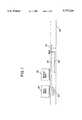
- FIG. 1is a schematic illustration displaying, in cross section, end portions of two sheet metal coils, joined by a butt weld and EMAT transmitter and receiver coils positioned near the weld, along with a one-dimensional path of travel of transmitted and reflected ultrasonic waves within the sheet metal.
- FIG. 2is an illustration of the present invention, pointing out the principal components thereof.
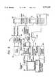
- FIG. 3is a schematic drawing of the electronics employed with the EMAT transmitter and receiver coil of the present invention.
- a typical sheet metal production and treatment line on which the present invention may be utilizedis comprised of a rolling mill, a plurality of roughing stands, a plurality of finishing stands, a first shearing apparatus, a welding apparatus, a temper mill, a pickling apparatus, a water rinse apparatus, a drying apparatus, a second shearing apparatus, a side splitter apparatus and a tandem cold mill.
- a long flat sheet of metal produced by the rolling millwill be wound into a coil after passing through the finishing stands.
- the coilwill then be transported to the first shearing apparatus located at another section of the factory and the end of that coil will be joined at the welding apparatus to the trailing end of another earlier transported coil which, for the most part, has already passed through a number of processing and treatment stations downstream of the welding apparatus.
- the location where the non-destructive weld test is madelies between the welding apparatus and the temper mill.
- FIG. 1provides a cross sectional visualization of end portions (20) of two sheet metal coils, which are connected by a butt weld (22) made by the welding apparatus. Also shown in FIG. 1, are an EMAT transmitter coil (24) and an EMAT receiver coil (26), both of which are positioned just downstream of the butt weld (22) on a surface of the end portion (20) of one of the sheet metal coils.
- EMAT transmitter coil (24)produces an ultrasonic SH shear wave (28) which travels through end portion (20) toward butt weld (22) where a fraction of the SH shear wave (28) passes through the butt weld (22) and a fraction of the wave passes back through the end portion (20) and toward the EMAT receiver coil (26) as a reflected wave (29).
- FIG. 2illustrates the fundamental components of the present invention.
- the present inventionhas a computer control unit (31) which is in electrical communication with the welding apparatus, an L-shaped transport apparatus (32) and a data acquisition unit (62), shown in FIG. 3.
- a first cable (33)provides the electrical connection between the computer control unit (31) and the welding apparatus.
- a second cable (34)electrically connects the computer control unit (31) to the transport apparatus (32).
- a third cable (37)links the computer control unit to the data acquisition unit (62).
- the transport apparatus (32)which is positioned just down stream of the butt weld (22), has housed within one of its ends the EMAT transmitter coil (24) and the EMAT receiver coil (26).
- An edge detection sensor (35)is affixed to the transport apparatus in proximity of the EMAT transmitter coil (24).
- the edge detection sensor (35)which is in electrical communication with the computer control unit (31), is used to position the EMAT coils (24) and (26) at an edge of the end portion (20) of one of the sheet metal coils and
- a flat, plate-like metal calibration station (36)which is used with the transport apparatus (32) to provide on-line checkout and manual adjustment of the EMAT transmitter coil (24) and the EMAT receiver coil (26) as well as other system electronics.
- FIG. 3provides a schematic illustration of the electronics employed with the EMAT transmitter coil (24) and the EMAT receiver coil (26).
- the electronics (50)include a power supply (51), a transmitter drive waveform generator (52), a programmable filter/gain module (53), a control bus computer interface (54), a first magnet pulser (55), a second magnet pulser (56), a gated power amp (57), a pre-amp (58), a transmitter matching network (59), a first magnet (60), and a second magnet (61) and an electrostatic shield (63).
- the power supply (51)provides electric current to the first magnet pulser (55) and to the second magnet pulser (56).
- the first magnet pulser (55)is connected to first magnet (60), and the second magnet pulser (56) is linked to second magnet (61).
- First magnet pulser (55) and second magnet pulser (56)generate high current pulses which are employed to charge first magnet (60) and second magnet (61), respectively.
- the transmitter drive waveform generator (52)is linked electrically to the second magnet pulser (56), the gated power amp (57), the programmable filter/gain module (53), and a data acquisition unit (62).
- a sync pulse and a transmitter triggerare provided to the transmitter wave form generator (52) from the data acquisition unit (62).
- a magnet drive pulseis provided to the second magnet pulser (56)
- a tone burstis provided to the gated power amp (57) and a gain shift is supplied to the programmable filter/gain module (53).
- the programmable filter/gain module (53)is in electrical,communication with the data acquisition unit (62), the pre-amp (58) and the control bus computer interface (54).
- a control busis provided from the control bus computer interface (54).
- a RF outputis supplied from the programmable filter/gain module (53) to the data acquisition unit (62).
- control bus computer interface (54)in addition to having an electrical connection with the programmable filter/gain module (53), has an electrical link to the data acquisition unit (62). Welding process parameters which have been stored on the data acquisition unit (62) are provided to the control bus computer interface (54).
- the gated power amp (57)is joined to the transmitter matching network (59) which is in turn linked to the EMAT transmitter coil (24).
- the pre-amp (58)is in electrical communication with the EMAT receiver coil (26) which is located within an electrostatic shield (63) and which receives the reflected SH shear wave (29) from the butt weld (22).
- the pre-amp (58) and the transmitter matching network (59)enable the EMAT coils (24 and 26) to be operated at distances greater than 100 feet from the computer control unit (31) and other electronic instrumentation which might be used along with the present invention.
Landscapes
- Physics & Mathematics (AREA)
- Biochemistry (AREA)
- Health & Medical Sciences (AREA)
- Life Sciences & Earth Sciences (AREA)
- Chemical & Material Sciences (AREA)
- Analytical Chemistry (AREA)
- General Health & Medical Sciences (AREA)
- General Physics & Mathematics (AREA)
- Immunology (AREA)
- Pathology (AREA)
- Electromagnetism (AREA)
- Investigating Or Analyzing Materials By The Use Of Ultrasonic Waves (AREA)
- Investigating Or Analyzing Materials By The Use Of Magnetic Means (AREA)
Abstract
Description
Claims (12)
Priority Applications (1)
| Application Number | Priority Date | Filing Date | Title |
|---|---|---|---|
| US08/668,957US5777229A (en) | 1994-07-18 | 1996-06-21 | Sensor transport system for combination flash butt welder |
Applications Claiming Priority (2)
| Application Number | Priority Date | Filing Date | Title |
|---|---|---|---|
| US27623094A | 1994-07-18 | 1994-07-18 | |
| US08/668,957US5777229A (en) | 1994-07-18 | 1996-06-21 | Sensor transport system for combination flash butt welder |
Related Parent Applications (1)
| Application Number | Title | Priority Date | Filing Date |
|---|---|---|---|
| US27623094AContinuation | 1994-07-18 | 1994-07-18 |
Publications (1)
| Publication Number | Publication Date |
|---|---|
| US5777229Atrue US5777229A (en) | 1998-07-07 |
Family
ID=23055757
Family Applications (1)
| Application Number | Title | Priority Date | Filing Date |
|---|---|---|---|
| US08/668,957Expired - Fee RelatedUS5777229A (en) | 1994-07-18 | 1996-06-21 | Sensor transport system for combination flash butt welder |
Country Status (4)
| Country | Link |
|---|---|
| US (1) | US5777229A (en) |
| EP (1) | EP0771419A4 (en) |
| AU (1) | AU2241695A (en) |
| WO (1) | WO1996002831A1 (en) |
Cited By (48)
| Publication number | Priority date | Publication date | Assignee | Title |
|---|---|---|---|---|
| US6684681B1 (en) | 2002-09-06 | 2004-02-03 | Siemens Westinghouse Power Corporation | Mechanical ultrasonic and high frequency sonic device |
| US20040134969A1 (en)* | 1999-03-08 | 2004-07-15 | Elpatronic Ag | Method and device for welding sheets |
| US6877555B2 (en) | 2001-04-24 | 2005-04-12 | Shell Oil Company | In situ thermal processing of an oil shale formation while inhibiting coking |
| US20050092715A1 (en)* | 2001-12-31 | 2005-05-05 | Alford Robert A. | Method for interconnecting tubulars by forge welding |
| US6932155B2 (en) | 2001-10-24 | 2005-08-23 | Shell Oil Company | In situ thermal processing of a hydrocarbon containing formation via backproducing through a heater well |
| US6948562B2 (en) | 2001-04-24 | 2005-09-27 | Shell Oil Company | Production of a blending agent using an in situ thermal process in a relatively permeable formation |
| US6969123B2 (en) | 2001-10-24 | 2005-11-29 | Shell Oil Company | Upgrading and mining of coal |
| US7011154B2 (en) | 2000-04-24 | 2006-03-14 | Shell Oil Company | In situ recovery from a kerogen and liquid hydrocarbon containing formation |
| US7040400B2 (en) | 2001-04-24 | 2006-05-09 | Shell Oil Company | In situ thermal processing of a relatively impermeable formation using an open wellbore |
| US7066254B2 (en) | 2001-04-24 | 2006-06-27 | Shell Oil Company | In situ thermal processing of a tar sands formation |
| US7073578B2 (en) | 2002-10-24 | 2006-07-11 | Shell Oil Company | Staged and/or patterned heating during in situ thermal processing of a hydrocarbon containing formation |
| US7077199B2 (en) | 2001-10-24 | 2006-07-18 | Shell Oil Company | In situ thermal processing of an oil reservoir formation |
| US7090013B2 (en) | 2001-10-24 | 2006-08-15 | Shell Oil Company | In situ thermal processing of a hydrocarbon containing formation to produce heated fluids |
| US7104319B2 (en) | 2001-10-24 | 2006-09-12 | Shell Oil Company | In situ thermal processing of a heavy oil diatomite formation |
| US7121342B2 (en) | 2003-04-24 | 2006-10-17 | Shell Oil Company | Thermal processes for subsurface formations |
| US7165615B2 (en) | 2001-10-24 | 2007-01-23 | Shell Oil Company | In situ recovery from a hydrocarbon containing formation using conductor-in-conduit heat sources with an electrically conductive material in the overburden |
| US7320364B2 (en) | 2004-04-23 | 2008-01-22 | Shell Oil Company | Inhibiting reflux in a heated well of an in situ conversion system |
| US7500528B2 (en) | 2005-04-22 | 2009-03-10 | Shell Oil Company | Low temperature barrier wellbores formed using water flushing |
| US7533719B2 (en) | 2006-04-21 | 2009-05-19 | Shell Oil Company | Wellhead with non-ferromagnetic materials |
| US7540324B2 (en) | 2006-10-20 | 2009-06-02 | Shell Oil Company | Heating hydrocarbon containing formations in a checkerboard pattern staged process |
| US20090140026A1 (en)* | 2006-04-11 | 2009-06-04 | Kawasaki Jukogyo Kabushiki Kaisha | Method and Apparatus for Inspecting Joined Object Formed by Friction Stir Joining |
| US20090151457A1 (en)* | 2005-11-21 | 2009-06-18 | Yukinori Iizuka | Ultrasonic Testing System and Ultrasonic Testing Technique for Pipe Member |
| US7549470B2 (en) | 2005-10-24 | 2009-06-23 | Shell Oil Company | Solution mining and heating by oxidation for treating hydrocarbon containing formations |
| US20090272526A1 (en)* | 2008-04-18 | 2009-11-05 | David Booth Burns | Electrical current flow between tunnels for use in heating subsurface hydrocarbon containing formations |
| EP1770393A3 (en)* | 2005-09-30 | 2010-05-26 | Airbus Operations S.L. | Ultrasonic head for pulse-echo multichannel inspection |
| US7798220B2 (en) | 2007-04-20 | 2010-09-21 | Shell Oil Company | In situ heat treatment of a tar sands formation after drive process treatment |
| US7798221B2 (en) | 2000-04-24 | 2010-09-21 | Shell Oil Company | In situ recovery from a hydrocarbon containing formation |
| US7866388B2 (en) | 2007-10-19 | 2011-01-11 | Shell Oil Company | High temperature methods for forming oxidizer fuel |
| US20110284508A1 (en)* | 2010-05-21 | 2011-11-24 | Kabushiki Kaisha Toshiba | Welding system and welding method |
| US8220539B2 (en) | 2008-10-13 | 2012-07-17 | Shell Oil Company | Controlling hydrogen pressure in self-regulating nuclear reactors used to treat a subsurface formation |
| US8327932B2 (en) | 2009-04-10 | 2012-12-11 | Shell Oil Company | Recovering energy from a subsurface formation |
| US20130200047A1 (en)* | 2012-02-08 | 2013-08-08 | Toyota Jidosha Kabushiki Kaisha | Spot welding apparatus and spot welding method |
| US8631866B2 (en) | 2010-04-09 | 2014-01-21 | Shell Oil Company | Leak detection in circulated fluid systems for heating subsurface formations |
| US8701768B2 (en) | 2010-04-09 | 2014-04-22 | Shell Oil Company | Methods for treating hydrocarbon formations |
| US8820406B2 (en) | 2010-04-09 | 2014-09-02 | Shell Oil Company | Electrodes for electrical current flow heating of subsurface formations with conductive material in wellbore |
| US9016370B2 (en) | 2011-04-08 | 2015-04-28 | Shell Oil Company | Partial solution mining of hydrocarbon containing layers prior to in situ heat treatment |
| US9033042B2 (en) | 2010-04-09 | 2015-05-19 | Shell Oil Company | Forming bitumen barriers in subsurface hydrocarbon formations |
| US9068326B2 (en) | 2009-06-30 | 2015-06-30 | Shanghai Kohler Electronics, Ltd. | Automatic sensing system and method for use with a plumbing fixture |
| US9217731B2 (en) | 2010-05-21 | 2015-12-22 | Kabushiki Kaisha Toshiba | Welding inspection method and apparatus thereof |
| US20160003751A1 (en)* | 2014-07-04 | 2016-01-07 | Georg Fischer Rohrleitungssysteme Ag | Contactless examination of a butt weld |
| US9309755B2 (en) | 2011-10-07 | 2016-04-12 | Shell Oil Company | Thermal expansion accommodation for circulated fluid systems used to heat subsurface formations |
| US9605524B2 (en) | 2012-01-23 | 2017-03-28 | Genie Ip B.V. | Heater pattern for in situ thermal processing of a subsurface hydrocarbon containing formation |
| US9726647B2 (en) | 2015-03-17 | 2017-08-08 | Hemosonics, Llc | Determining mechanical properties via ultrasound-induced resonance |
| US10047594B2 (en) | 2012-01-23 | 2018-08-14 | Genie Ip B.V. | Heater pattern for in situ thermal processing of a subsurface hydrocarbon containing formation |
| US20180313790A1 (en)* | 2017-04-28 | 2018-11-01 | GM Global Technology Operations LLC | Portable acoustic apparatus for in-situ monitoring of a weld in a workpiece |
| CN112065362A (en)* | 2020-09-24 | 2020-12-11 | 东北石油大学 | Anti-interference type natural potential logging device and method |
| US10962524B2 (en) | 2011-02-15 | 2021-03-30 | HomoSonics LLC | Characterization of blood hemostasis and oxygen transport parameters |
| US11585788B2 (en)* | 2016-10-19 | 2023-02-21 | Saipem S.A | Method for automatically inspecting a weld bead deposited in a chamfer formed between two metal pieces to be assembled |
Families Citing this family (5)
| Publication number | Priority date | Publication date | Assignee | Title |
|---|---|---|---|---|
| US5652389A (en)* | 1996-05-22 | 1997-07-29 | The United States Of America As Represented By The Secretary Of Commerce | Non-contact method and apparatus for inspection of inertia welds |
| CA2492668C (en)* | 2002-07-17 | 2011-08-09 | Shell Canada Limited | Electromagnetic acoustic transducer (emat) weld inspection |
| DK1531959T3 (en) | 2002-07-17 | 2008-06-16 | Shell Int Research | Method of joining extensible tubes |
| US7282663B2 (en)* | 2002-07-29 | 2007-10-16 | Shell Oil Company | Forge welding process |
| US7774917B2 (en) | 2003-07-17 | 2010-08-17 | Tubefuse Applications B.V. | Forge welding tubulars |
Citations (16)
| Publication number | Priority date | Publication date | Assignee | Title |
|---|---|---|---|---|
| US3575042A (en)* | 1968-08-28 | 1971-04-13 | Gen Dynamics Corp | Automatic digital recording weld defect detector |
| US3850028A (en)* | 1972-11-16 | 1974-11-26 | Rockwell International Corp | Method for ultrasonic inspection |
| US3861574A (en)* | 1972-03-15 | 1975-01-21 | Ralf Hoffmann | Apparatus for the production and/or testing of welded helical seam pipe |
| US4058002A (en)* | 1976-12-23 | 1977-11-15 | The United States Of America As Represented By The Secretary Of The Air Force | Dispersive electromagnetic surface acoustic wave transducer |
| US4100809A (en)* | 1975-07-28 | 1978-07-18 | Vladimir Timofeevich Bobrov | Method for excitation and reception of ultrasonic plate waves in workpieces and devices for realizing same |
| US4289030A (en)* | 1979-08-01 | 1981-09-15 | Rockwell International Corporation | Nondestructive testing utilizing horizontally polarized shear waves |
| US4295214A (en)* | 1979-08-23 | 1981-10-13 | Rockwell International Corporation | Ultrasonic shear wave transducer |
| US4294118A (en)* | 1979-10-29 | 1981-10-13 | Sumitomo Kinzoku Kogyo Kabushiki Kaisha | Fully automatic ultrasonic flaw detection apparatus |
| US4296486A (en)* | 1980-01-24 | 1981-10-20 | Rockwell International Corporation | Shielded electromagnetic acoustic transducers |
| US4578909A (en)* | 1982-12-30 | 1986-04-01 | Enercept, Inc. | Insulated building construction |
| US4627289A (en)* | 1984-11-06 | 1986-12-09 | Nippon Steel Corporation | Method for the ultrasonic flaw detection of an electric welded pipe |
| US5062301A (en)* | 1987-12-10 | 1991-11-05 | Aleshin Nikolai P | Scanning device for ultrasonic quality control of articles |
| US5154081A (en)* | 1989-07-21 | 1992-10-13 | Iowa State University Research Foundation, Inc. | Means and method for ultrasonic measurement of material properties |
| US5439157A (en)* | 1994-07-18 | 1995-08-08 | The Babcock & Wilcox Company | Automated butt weld inspection system |
| US5474225A (en)* | 1994-07-18 | 1995-12-12 | The Babcock & Wilcox Company | Automated method for butt weld inspection and defect diagnosis |
| US5537876A (en)* | 1994-08-02 | 1996-07-23 | Davidson; Paul K. | Apparatus and method for nondestructive evaluation of butt welds |
Family Cites Families (1)
| Publication number | Priority date | Publication date | Assignee | Title |
|---|---|---|---|---|
| US4578999A (en)* | 1982-02-10 | 1986-04-01 | Mannesmann A.G. | Instrument for testing materials |
- 1995
- 1995-04-06WOPCT/US1995/004232patent/WO1996002831A1/ennot_activeApplication Discontinuation
- 1995-04-06AUAU22416/95Apatent/AU2241695A/ennot_activeAbandoned
- 1995-04-06EPEP95915573Apatent/EP0771419A4/ennot_activeWithdrawn
- 1996
- 1996-06-21USUS08/668,957patent/US5777229A/ennot_activeExpired - Fee Related
Patent Citations (16)
| Publication number | Priority date | Publication date | Assignee | Title |
|---|---|---|---|---|
| US3575042A (en)* | 1968-08-28 | 1971-04-13 | Gen Dynamics Corp | Automatic digital recording weld defect detector |
| US3861574A (en)* | 1972-03-15 | 1975-01-21 | Ralf Hoffmann | Apparatus for the production and/or testing of welded helical seam pipe |
| US3850028A (en)* | 1972-11-16 | 1974-11-26 | Rockwell International Corp | Method for ultrasonic inspection |
| US4100809A (en)* | 1975-07-28 | 1978-07-18 | Vladimir Timofeevich Bobrov | Method for excitation and reception of ultrasonic plate waves in workpieces and devices for realizing same |
| US4058002A (en)* | 1976-12-23 | 1977-11-15 | The United States Of America As Represented By The Secretary Of The Air Force | Dispersive electromagnetic surface acoustic wave transducer |
| US4289030A (en)* | 1979-08-01 | 1981-09-15 | Rockwell International Corporation | Nondestructive testing utilizing horizontally polarized shear waves |
| US4295214A (en)* | 1979-08-23 | 1981-10-13 | Rockwell International Corporation | Ultrasonic shear wave transducer |
| US4294118A (en)* | 1979-10-29 | 1981-10-13 | Sumitomo Kinzoku Kogyo Kabushiki Kaisha | Fully automatic ultrasonic flaw detection apparatus |
| US4296486A (en)* | 1980-01-24 | 1981-10-20 | Rockwell International Corporation | Shielded electromagnetic acoustic transducers |
| US4578909A (en)* | 1982-12-30 | 1986-04-01 | Enercept, Inc. | Insulated building construction |
| US4627289A (en)* | 1984-11-06 | 1986-12-09 | Nippon Steel Corporation | Method for the ultrasonic flaw detection of an electric welded pipe |
| US5062301A (en)* | 1987-12-10 | 1991-11-05 | Aleshin Nikolai P | Scanning device for ultrasonic quality control of articles |
| US5154081A (en)* | 1989-07-21 | 1992-10-13 | Iowa State University Research Foundation, Inc. | Means and method for ultrasonic measurement of material properties |
| US5439157A (en)* | 1994-07-18 | 1995-08-08 | The Babcock & Wilcox Company | Automated butt weld inspection system |
| US5474225A (en)* | 1994-07-18 | 1995-12-12 | The Babcock & Wilcox Company | Automated method for butt weld inspection and defect diagnosis |
| US5537876A (en)* | 1994-08-02 | 1996-07-23 | Davidson; Paul K. | Apparatus and method for nondestructive evaluation of butt welds |
Non-Patent Citations (14)
| Title |
|---|
| Brochure entitled "EMAT Inspection Systems for Non-Destructive Testing", published Sep. 1993 by The Babcock & Wilcox Company, CIM Systems, Lynchburg, VA. |
| Brochure entitled Automated Butt Weld Inspection System, published Aug. 1993 by The Taylor Winfield Corp., Warren, OH.* |
| Brochure entitled Automated Butt-Weld Inspection System, published Aug. 1993 by The Taylor-Winfield Corp., Warren, OH. |
| Brochure entitled EMAT Inspection Systems for Non Destructive Testing , published Sep. 1993 by The Babcock & Wilcox Company, CIM Systems, Lynchburg, VA.* |
| Brochure entitled: "Butt Weld Inspection and Weld Machine Diagnostic System", published Jul. 1994 by The Babcock & Wilcox Company, Innerspec Technologies, Lynchburg, VA. |
| Brochure entitled: Butt Weld Inspection and Weld Machine Diagnostic System , published Jul. 1994 by The Babcock & Wilcox Company, Innerspec Technologies, Lynchburg, VA.* |
| Proposal #9315SA06295.017 Rev. A., dated Sep. 13, 1993 and made to Armco Steel Company, L.P. by The Taylor-Winfield Corp.; Re: Automated Flash Butt Welder Inspection System for #4 Pickle Line Welder. |
| Proposal #CB-011-B-00, dated Sep. 24, 1993 and made to Armco Steel Company L.P. by The Babcock & Wilcox Company; Re: Welder Diagnostic System. |
| Proposal 9315SA06295.017 Rev. A., dated Sep. 13, 1993 and made to Armco Steel Company, L.P. by The Taylor Winfield Corp.; Re: Automated Flash Butt Welder Inspection System for 4 Pickle Line Welder.* |
| Proposal CB 011 B 00, dated Sep. 24, 1993 and made to Armco Steel Company L.P. by The Babcock & Wilcox Company; Re: Welder Diagnostic System.* |
| Specification entitled "Armco Spec RES 1174 (Inquiry #M-1174-00)", dated Nov. 7, 1993, issued by Armco Steel Company L.P. for No. 4 Pickle Line Automated Flash Butt Welder Inspection System. |
| Specification entitled Armco Spec RES 1174 (Inquiry M 1174 00) , dated Nov. 7, 1993, issued by Armco Steel Company L.P. for No. 4 Pickle Line Automated Flash Butt Welder Inspection System.* |
| Technical Article by D.T. MacLauchlin, G.A. Alers and J.J. Jackson, "Detection and Measurement of Defects in Butt Welds", Review of Progress in Quantitative Nondestructive Evaluaton, 1989, pp. 1039-1046. |
| Technical Article by D.T. MacLauchlin, G.A. Alers and J.J. Jackson, Detection and Measurement of Defects in Butt Welds , Review of Progress in Quantitative Nondestructive Evaluaton, 1989, pp. 1039 1046.* |
Cited By (229)
| Publication number | Priority date | Publication date | Assignee | Title |
|---|---|---|---|---|
| US20040134969A1 (en)* | 1999-03-08 | 2004-07-15 | Elpatronic Ag | Method and device for welding sheets |
| US7798221B2 (en) | 2000-04-24 | 2010-09-21 | Shell Oil Company | In situ recovery from a hydrocarbon containing formation |
| US8789586B2 (en) | 2000-04-24 | 2014-07-29 | Shell Oil Company | In situ recovery from a hydrocarbon containing formation |
| US7011154B2 (en) | 2000-04-24 | 2006-03-14 | Shell Oil Company | In situ recovery from a kerogen and liquid hydrocarbon containing formation |
| US8485252B2 (en) | 2000-04-24 | 2013-07-16 | Shell Oil Company | In situ recovery from a hydrocarbon containing formation |
| US8225866B2 (en) | 2000-04-24 | 2012-07-24 | Shell Oil Company | In situ recovery from a hydrocarbon containing formation |
| US6991036B2 (en) | 2001-04-24 | 2006-01-31 | Shell Oil Company | Thermal processing of a relatively permeable formation |
| US6994169B2 (en) | 2001-04-24 | 2006-02-07 | Shell Oil Company | In situ thermal processing of an oil shale formation with a selected property |
| US6923257B2 (en) | 2001-04-24 | 2005-08-02 | Shell Oil Company | In situ thermal processing of an oil shale formation to produce a condensate |
| US6929067B2 (en) | 2001-04-24 | 2005-08-16 | Shell Oil Company | Heat sources with conductive material for in situ thermal processing of an oil shale formation |
| US6918442B2 (en) | 2001-04-24 | 2005-07-19 | Shell Oil Company | In situ thermal processing of an oil shale formation in a reducing environment |
| US6948562B2 (en) | 2001-04-24 | 2005-09-27 | Shell Oil Company | Production of a blending agent using an in situ thermal process in a relatively permeable formation |
| US6951247B2 (en) | 2001-04-24 | 2005-10-04 | Shell Oil Company | In situ thermal processing of an oil shale formation using horizontal heat sources |
| US6964300B2 (en) | 2001-04-24 | 2005-11-15 | Shell Oil Company | In situ thermal recovery from a relatively permeable formation with backproduction through a heater wellbore |
| US6966374B2 (en) | 2001-04-24 | 2005-11-22 | Shell Oil Company | In situ thermal recovery from a relatively permeable formation using gas to increase mobility |
| US6915850B2 (en) | 2001-04-24 | 2005-07-12 | Shell Oil Company | In situ thermal processing of an oil shale formation having permeable and impermeable sections |
| US6981548B2 (en) | 2001-04-24 | 2006-01-03 | Shell Oil Company | In situ thermal recovery from a relatively permeable formation |
| US6991032B2 (en) | 2001-04-24 | 2006-01-31 | Shell Oil Company | In situ thermal processing of an oil shale formation using a pattern of heat sources |
| US7096942B1 (en) | 2001-04-24 | 2006-08-29 | Shell Oil Company | In situ thermal processing of a relatively permeable formation while controlling pressure |
| US7735935B2 (en) | 2001-04-24 | 2010-06-15 | Shell Oil Company | In situ thermal processing of an oil shale formation containing carbonate minerals |
| US6991033B2 (en) | 2001-04-24 | 2006-01-31 | Shell Oil Company | In situ thermal processing while controlling pressure in an oil shale formation |
| US6918443B2 (en) | 2001-04-24 | 2005-07-19 | Shell Oil Company | In situ thermal processing of an oil shale formation to produce hydrocarbons having a selected carbon number range |
| US6997518B2 (en) | 2001-04-24 | 2006-02-14 | Shell Oil Company | In situ thermal processing and solution mining of an oil shale formation |
| US7004247B2 (en) | 2001-04-24 | 2006-02-28 | Shell Oil Company | Conductor-in-conduit heat sources for in situ thermal processing of an oil shale formation |
| US7004251B2 (en) | 2001-04-24 | 2006-02-28 | Shell Oil Company | In situ thermal processing and remediation of an oil shale formation |
| US6880633B2 (en) | 2001-04-24 | 2005-04-19 | Shell Oil Company | In situ thermal processing of an oil shale formation to produce a desired product |
| US7013972B2 (en) | 2001-04-24 | 2006-03-21 | Shell Oil Company | In situ thermal processing of an oil shale formation using a natural distributed combustor |
| US7032660B2 (en) | 2001-04-24 | 2006-04-25 | Shell Oil Company | In situ thermal processing and inhibiting migration of fluids into or out of an in situ oil shale formation |
| US7040400B2 (en) | 2001-04-24 | 2006-05-09 | Shell Oil Company | In situ thermal processing of a relatively impermeable formation using an open wellbore |
| US7040399B2 (en) | 2001-04-24 | 2006-05-09 | Shell Oil Company | In situ thermal processing of an oil shale formation using a controlled heating rate |
| US7040398B2 (en) | 2001-04-24 | 2006-05-09 | Shell Oil Company | In situ thermal processing of a relatively permeable formation in a reducing environment |
| US7051807B2 (en) | 2001-04-24 | 2006-05-30 | Shell Oil Company | In situ thermal recovery from a relatively permeable formation with quality control |
| US8608249B2 (en) | 2001-04-24 | 2013-12-17 | Shell Oil Company | In situ thermal processing of an oil shale formation |
| US7051811B2 (en) | 2001-04-24 | 2006-05-30 | Shell Oil Company | In situ thermal processing through an open wellbore in an oil shale formation |
| US7055600B2 (en) | 2001-04-24 | 2006-06-06 | Shell Oil Company | In situ thermal recovery from a relatively permeable formation with controlled production rate |
| US6877555B2 (en) | 2001-04-24 | 2005-04-12 | Shell Oil Company | In situ thermal processing of an oil shale formation while inhibiting coking |
| US7066254B2 (en) | 2001-04-24 | 2006-06-27 | Shell Oil Company | In situ thermal processing of a tar sands formation |
| US7225866B2 (en) | 2001-04-24 | 2007-06-05 | Shell Oil Company | In situ thermal processing of an oil shale formation using a pattern of heat sources |
| US7077198B2 (en) | 2001-10-24 | 2006-07-18 | Shell Oil Company | In situ recovery from a hydrocarbon containing formation using barriers |
| US7461691B2 (en) | 2001-10-24 | 2008-12-09 | Shell Oil Company | In situ recovery from a hydrocarbon containing formation |
| US20100126727A1 (en)* | 2001-10-24 | 2010-05-27 | Shell Oil Company | In situ recovery from a hydrocarbon containing formation |
| US7086465B2 (en) | 2001-10-24 | 2006-08-08 | Shell Oil Company | In situ production of a blending agent from a hydrocarbon containing formation |
| US7090013B2 (en) | 2001-10-24 | 2006-08-15 | Shell Oil Company | In situ thermal processing of a hydrocarbon containing formation to produce heated fluids |
| US8627887B2 (en) | 2001-10-24 | 2014-01-14 | Shell Oil Company | In situ recovery from a hydrocarbon containing formation |
| US7100994B2 (en) | 2001-10-24 | 2006-09-05 | Shell Oil Company | Producing hydrocarbons and non-hydrocarbon containing materials when treating a hydrocarbon containing formation |
| US7104319B2 (en) | 2001-10-24 | 2006-09-12 | Shell Oil Company | In situ thermal processing of a heavy oil diatomite formation |
| US7051808B1 (en) | 2001-10-24 | 2006-05-30 | Shell Oil Company | Seismic monitoring of in situ conversion in a hydrocarbon containing formation |
| US6969123B2 (en) | 2001-10-24 | 2005-11-29 | Shell Oil Company | Upgrading and mining of coal |
| US7128153B2 (en) | 2001-10-24 | 2006-10-31 | Shell Oil Company | Treatment of a hydrocarbon containing formation after heating |
| US7156176B2 (en) | 2001-10-24 | 2007-01-02 | Shell Oil Company | Installation and use of removable heaters in a hydrocarbon containing formation |
| US7165615B2 (en) | 2001-10-24 | 2007-01-23 | Shell Oil Company | In situ recovery from a hydrocarbon containing formation using conductor-in-conduit heat sources with an electrically conductive material in the overburden |
| US7063145B2 (en) | 2001-10-24 | 2006-06-20 | Shell Oil Company | Methods and systems for heating a hydrocarbon containing formation in situ with an opening contacting the earth's surface at two locations |
| US7077199B2 (en) | 2001-10-24 | 2006-07-18 | Shell Oil Company | In situ thermal processing of an oil reservoir formation |
| US7066257B2 (en) | 2001-10-24 | 2006-06-27 | Shell Oil Company | In situ recovery from lean and rich zones in a hydrocarbon containing formation |
| US6932155B2 (en) | 2001-10-24 | 2005-08-23 | Shell Oil Company | In situ thermal processing of a hydrocarbon containing formation via backproducing through a heater well |
| US6991045B2 (en) | 2001-10-24 | 2006-01-31 | Shell Oil Company | Forming openings in a hydrocarbon containing formation using magnetic tracking |
| US7199325B2 (en) | 2001-12-31 | 2007-04-03 | Shell Oil Company | Method for interconnecting tubulars by forge welding |
| US20050092715A1 (en)* | 2001-12-31 | 2005-05-05 | Alford Robert A. | Method for interconnecting tubulars by forge welding |
| US6684681B1 (en) | 2002-09-06 | 2004-02-03 | Siemens Westinghouse Power Corporation | Mechanical ultrasonic and high frequency sonic device |
| US8224163B2 (en) | 2002-10-24 | 2012-07-17 | Shell Oil Company | Variable frequency temperature limited heaters |
| US8224164B2 (en) | 2002-10-24 | 2012-07-17 | Shell Oil Company | Insulated conductor temperature limited heaters |
| US8238730B2 (en) | 2002-10-24 | 2012-08-07 | Shell Oil Company | High voltage temperature limited heaters |
| US7219734B2 (en) | 2002-10-24 | 2007-05-22 | Shell Oil Company | Inhibiting wellbore deformation during in situ thermal processing of a hydrocarbon containing formation |
| US7121341B2 (en) | 2002-10-24 | 2006-10-17 | Shell Oil Company | Conductor-in-conduit temperature limited heaters |
| US7073578B2 (en) | 2002-10-24 | 2006-07-11 | Shell Oil Company | Staged and/or patterned heating during in situ thermal processing of a hydrocarbon containing formation |
| US8579031B2 (en) | 2003-04-24 | 2013-11-12 | Shell Oil Company | Thermal processes for subsurface formations |
| US7360588B2 (en) | 2003-04-24 | 2008-04-22 | Shell Oil Company | Thermal processes for subsurface formations |
| US7640980B2 (en) | 2003-04-24 | 2010-01-05 | Shell Oil Company | Thermal processes for subsurface formations |
| US7121342B2 (en) | 2003-04-24 | 2006-10-17 | Shell Oil Company | Thermal processes for subsurface formations |
| US7942203B2 (en) | 2003-04-24 | 2011-05-17 | Shell Oil Company | Thermal processes for subsurface formations |
| US7383877B2 (en) | 2004-04-23 | 2008-06-10 | Shell Oil Company | Temperature limited heaters with thermally conductive fluid used to heat subsurface formations |
| US8355623B2 (en) | 2004-04-23 | 2013-01-15 | Shell Oil Company | Temperature limited heaters with high power factors |
| US7510000B2 (en) | 2004-04-23 | 2009-03-31 | Shell Oil Company | Reducing viscosity of oil for production from a hydrocarbon containing formation |
| US7370704B2 (en) | 2004-04-23 | 2008-05-13 | Shell Oil Company | Triaxial temperature limited heater |
| US7424915B2 (en) | 2004-04-23 | 2008-09-16 | Shell Oil Company | Vacuum pumping of conductor-in-conduit heaters |
| US7357180B2 (en) | 2004-04-23 | 2008-04-15 | Shell Oil Company | Inhibiting effects of sloughing in wellbores |
| US7431076B2 (en) | 2004-04-23 | 2008-10-07 | Shell Oil Company | Temperature limited heaters using modulated DC power |
| US7353872B2 (en) | 2004-04-23 | 2008-04-08 | Shell Oil Company | Start-up of temperature limited heaters using direct current (DC) |
| US7320364B2 (en) | 2004-04-23 | 2008-01-22 | Shell Oil Company | Inhibiting reflux in a heated well of an in situ conversion system |
| US7481274B2 (en) | 2004-04-23 | 2009-01-27 | Shell Oil Company | Temperature limited heaters with relatively constant current |
| US7490665B2 (en) | 2004-04-23 | 2009-02-17 | Shell Oil Company | Variable frequency temperature limited heaters |
| US7831134B2 (en) | 2005-04-22 | 2010-11-09 | Shell Oil Company | Grouped exposed metal heaters |
| US7546873B2 (en) | 2005-04-22 | 2009-06-16 | Shell Oil Company | Low temperature barriers for use with in situ processes |
| US8224165B2 (en) | 2005-04-22 | 2012-07-17 | Shell Oil Company | Temperature limited heater utilizing non-ferromagnetic conductor |
| US8233782B2 (en) | 2005-04-22 | 2012-07-31 | Shell Oil Company | Grouped exposed metal heaters |
| US8070840B2 (en) | 2005-04-22 | 2011-12-06 | Shell Oil Company | Treatment of gas from an in situ conversion process |
| US8230927B2 (en) | 2005-04-22 | 2012-07-31 | Shell Oil Company | Methods and systems for producing fluid from an in situ conversion process |
| US8027571B2 (en) | 2005-04-22 | 2011-09-27 | Shell Oil Company | In situ conversion process systems utilizing wellbores in at least two regions of a formation |
| US7575053B2 (en) | 2005-04-22 | 2009-08-18 | Shell Oil Company | Low temperature monitoring system for subsurface barriers |
| US7986869B2 (en) | 2005-04-22 | 2011-07-26 | Shell Oil Company | Varying properties along lengths of temperature limited heaters |
| US7942197B2 (en) | 2005-04-22 | 2011-05-17 | Shell Oil Company | Methods and systems for producing fluid from an in situ conversion process |
| US7860377B2 (en) | 2005-04-22 | 2010-12-28 | Shell Oil Company | Subsurface connection methods for subsurface heaters |
| US7527094B2 (en) | 2005-04-22 | 2009-05-05 | Shell Oil Company | Double barrier system for an in situ conversion process |
| US7500528B2 (en) | 2005-04-22 | 2009-03-10 | Shell Oil Company | Low temperature barrier wellbores formed using water flushing |
| US7575052B2 (en) | 2005-04-22 | 2009-08-18 | Shell Oil Company | In situ conversion process utilizing a closed loop heating system |
| EP1770393A3 (en)* | 2005-09-30 | 2010-05-26 | Airbus Operations S.L. | Ultrasonic head for pulse-echo multichannel inspection |
| US7559367B2 (en) | 2005-10-24 | 2009-07-14 | Shell Oil Company | Temperature limited heater with a conduit substantially electrically isolated from the formation |
| US8606091B2 (en) | 2005-10-24 | 2013-12-10 | Shell Oil Company | Subsurface heaters with low sulfidation rates |
| US7556096B2 (en) | 2005-10-24 | 2009-07-07 | Shell Oil Company | Varying heating in dawsonite zones in hydrocarbon containing formations |
| US7584789B2 (en) | 2005-10-24 | 2009-09-08 | Shell Oil Company | Methods of cracking a crude product to produce additional crude products |
| US8151880B2 (en) | 2005-10-24 | 2012-04-10 | Shell Oil Company | Methods of making transportation fuel |
| US7556095B2 (en) | 2005-10-24 | 2009-07-07 | Shell Oil Company | Solution mining dawsonite from hydrocarbon containing formations with a chelating agent |
| US7549470B2 (en) | 2005-10-24 | 2009-06-23 | Shell Oil Company | Solution mining and heating by oxidation for treating hydrocarbon containing formations |
| US7591310B2 (en) | 2005-10-24 | 2009-09-22 | Shell Oil Company | Methods of hydrotreating a liquid stream to remove clogging compounds |
| US7559368B2 (en) | 2005-10-24 | 2009-07-14 | Shell Oil Company | Solution mining systems and methods for treating hydrocarbon containing formations |
| US7581589B2 (en) | 2005-10-24 | 2009-09-01 | Shell Oil Company | Methods of producing alkylated hydrocarbons from an in situ heat treatment process liquid |
| US7562706B2 (en) | 2005-10-24 | 2009-07-21 | Shell Oil Company | Systems and methods for producing hydrocarbons from tar sands formations |
| US7635025B2 (en) | 2005-10-24 | 2009-12-22 | Shell Oil Company | Cogeneration systems and processes for treating hydrocarbon containing formations |
| US7779694B2 (en)* | 2005-11-21 | 2010-08-24 | Jfe Steel Corporation | Ultrasonic testing system and ultrasonic testing technique for pipe member |
| US20090151457A1 (en)* | 2005-11-21 | 2009-06-18 | Yukinori Iizuka | Ultrasonic Testing System and Ultrasonic Testing Technique for Pipe Member |
| US7861910B2 (en)* | 2006-04-11 | 2011-01-04 | Kawasaki Jukogyo Kabushiki Kaisha | Method and apparatus for inspecting joined object formed by friction stir joining |
| US8590766B2 (en) | 2006-04-11 | 2013-11-26 | Kawasaki Jukogyo Kabushiki Kaisha | Method and apparatus for inspecting joined object formed by friction stir joining |
| US20090140026A1 (en)* | 2006-04-11 | 2009-06-04 | Kawasaki Jukogyo Kabushiki Kaisha | Method and Apparatus for Inspecting Joined Object Formed by Friction Stir Joining |
| US8857506B2 (en) | 2006-04-21 | 2014-10-14 | Shell Oil Company | Alternate energy source usage methods for in situ heat treatment processes |
| US8083813B2 (en) | 2006-04-21 | 2011-12-27 | Shell Oil Company | Methods of producing transportation fuel |
| US7793722B2 (en) | 2006-04-21 | 2010-09-14 | Shell Oil Company | Non-ferromagnetic overburden casing |
| US7683296B2 (en) | 2006-04-21 | 2010-03-23 | Shell Oil Company | Adjusting alloy compositions for selected properties in temperature limited heaters |
| US7785427B2 (en) | 2006-04-21 | 2010-08-31 | Shell Oil Company | High strength alloys |
| US7635023B2 (en) | 2006-04-21 | 2009-12-22 | Shell Oil Company | Time sequenced heating of multiple layers in a hydrocarbon containing formation |
| US7533719B2 (en) | 2006-04-21 | 2009-05-19 | Shell Oil Company | Wellhead with non-ferromagnetic materials |
| US7597147B2 (en) | 2006-04-21 | 2009-10-06 | Shell Oil Company | Temperature limited heaters using phase transformation of ferromagnetic material |
| US7604052B2 (en) | 2006-04-21 | 2009-10-20 | Shell Oil Company | Compositions produced using an in situ heat treatment process |
| US7610962B2 (en) | 2006-04-21 | 2009-11-03 | Shell Oil Company | Sour gas injection for use with in situ heat treatment |
| US7673786B2 (en) | 2006-04-21 | 2010-03-09 | Shell Oil Company | Welding shield for coupling heaters |
| US7631689B2 (en) | 2006-04-21 | 2009-12-15 | Shell Oil Company | Sulfur barrier for use with in situ processes for treating formations |
| US8192682B2 (en) | 2006-04-21 | 2012-06-05 | Shell Oil Company | High strength alloys |
| US7866385B2 (en) | 2006-04-21 | 2011-01-11 | Shell Oil Company | Power systems utilizing the heat of produced formation fluid |
| US7912358B2 (en) | 2006-04-21 | 2011-03-22 | Shell Oil Company | Alternate energy source usage for in situ heat treatment processes |
| US7562707B2 (en) | 2006-10-20 | 2009-07-21 | Shell Oil Company | Heating hydrocarbon containing formations in a line drive staged process |
| US7841401B2 (en) | 2006-10-20 | 2010-11-30 | Shell Oil Company | Gas injection to inhibit migration during an in situ heat treatment process |
| US7730947B2 (en) | 2006-10-20 | 2010-06-08 | Shell Oil Company | Creating fluid injectivity in tar sands formations |
| US7644765B2 (en) | 2006-10-20 | 2010-01-12 | Shell Oil Company | Heating tar sands formations while controlling pressure |
| US7631690B2 (en) | 2006-10-20 | 2009-12-15 | Shell Oil Company | Heating hydrocarbon containing formations in a spiral startup staged sequence |
| US7730945B2 (en) | 2006-10-20 | 2010-06-08 | Shell Oil Company | Using geothermal energy to heat a portion of a formation for an in situ heat treatment process |
| US7730946B2 (en) | 2006-10-20 | 2010-06-08 | Shell Oil Company | Treating tar sands formations with dolomite |
| US7673681B2 (en) | 2006-10-20 | 2010-03-09 | Shell Oil Company | Treating tar sands formations with karsted zones |
| US7540324B2 (en) | 2006-10-20 | 2009-06-02 | Shell Oil Company | Heating hydrocarbon containing formations in a checkerboard pattern staged process |
| US8555971B2 (en) | 2006-10-20 | 2013-10-15 | Shell Oil Company | Treating tar sands formations with dolomite |
| US7845411B2 (en) | 2006-10-20 | 2010-12-07 | Shell Oil Company | In situ heat treatment process utilizing a closed loop heating system |
| US7717171B2 (en) | 2006-10-20 | 2010-05-18 | Shell Oil Company | Moving hydrocarbons through portions of tar sands formations with a fluid |
| US7703513B2 (en) | 2006-10-20 | 2010-04-27 | Shell Oil Company | Wax barrier for use with in situ processes for treating formations |
| US7635024B2 (en) | 2006-10-20 | 2009-12-22 | Shell Oil Company | Heating tar sands formations to visbreaking temperatures |
| US7681647B2 (en) | 2006-10-20 | 2010-03-23 | Shell Oil Company | Method of producing drive fluid in situ in tar sands formations |
| US7677314B2 (en) | 2006-10-20 | 2010-03-16 | Shell Oil Company | Method of condensing vaporized water in situ to treat tar sands formations |
| US7677310B2 (en) | 2006-10-20 | 2010-03-16 | Shell Oil Company | Creating and maintaining a gas cap in tar sands formations |
| US8191630B2 (en) | 2006-10-20 | 2012-06-05 | Shell Oil Company | Creating fluid injectivity in tar sands formations |
| US7841408B2 (en) | 2007-04-20 | 2010-11-30 | Shell Oil Company | In situ heat treatment from multiple layers of a tar sands formation |
| US8791396B2 (en) | 2007-04-20 | 2014-07-29 | Shell Oil Company | Floating insulated conductors for heating subsurface formations |
| US7931086B2 (en) | 2007-04-20 | 2011-04-26 | Shell Oil Company | Heating systems for heating subsurface formations |
| US7849922B2 (en) | 2007-04-20 | 2010-12-14 | Shell Oil Company | In situ recovery from residually heated sections in a hydrocarbon containing formation |
| US7950453B2 (en) | 2007-04-20 | 2011-05-31 | Shell Oil Company | Downhole burner systems and methods for heating subsurface formations |
| US8459359B2 (en) | 2007-04-20 | 2013-06-11 | Shell Oil Company | Treating nahcolite containing formations and saline zones |
| US7841425B2 (en) | 2007-04-20 | 2010-11-30 | Shell Oil Company | Drilling subsurface wellbores with cutting structures |
| US7832484B2 (en) | 2007-04-20 | 2010-11-16 | Shell Oil Company | Molten salt as a heat transfer fluid for heating a subsurface formation |
| US8381815B2 (en) | 2007-04-20 | 2013-02-26 | Shell Oil Company | Production from multiple zones of a tar sands formation |
| US8662175B2 (en) | 2007-04-20 | 2014-03-04 | Shell Oil Company | Varying properties of in situ heat treatment of a tar sands formation based on assessed viscosities |
| US8327681B2 (en) | 2007-04-20 | 2012-12-11 | Shell Oil Company | Wellbore manufacturing processes for in situ heat treatment processes |
| US9181780B2 (en) | 2007-04-20 | 2015-11-10 | Shell Oil Company | Controlling and assessing pressure conditions during treatment of tar sands formations |
| US8042610B2 (en) | 2007-04-20 | 2011-10-25 | Shell Oil Company | Parallel heater system for subsurface formations |
| US7798220B2 (en) | 2007-04-20 | 2010-09-21 | Shell Oil Company | In situ heat treatment of a tar sands formation after drive process treatment |
| US8146669B2 (en) | 2007-10-19 | 2012-04-03 | Shell Oil Company | Multi-step heater deployment in a subsurface formation |
| US8162059B2 (en) | 2007-10-19 | 2012-04-24 | Shell Oil Company | Induction heaters used to heat subsurface formations |
| US8240774B2 (en) | 2007-10-19 | 2012-08-14 | Shell Oil Company | Solution mining and in situ treatment of nahcolite beds |
| US7866386B2 (en) | 2007-10-19 | 2011-01-11 | Shell Oil Company | In situ oxidation of subsurface formations |
| US8272455B2 (en) | 2007-10-19 | 2012-09-25 | Shell Oil Company | Methods for forming wellbores in heated formations |
| US8276661B2 (en) | 2007-10-19 | 2012-10-02 | Shell Oil Company | Heating subsurface formations by oxidizing fuel on a fuel carrier |
| US8536497B2 (en) | 2007-10-19 | 2013-09-17 | Shell Oil Company | Methods for forming long subsurface heaters |
| US8113272B2 (en) | 2007-10-19 | 2012-02-14 | Shell Oil Company | Three-phase heaters with common overburden sections for heating subsurface formations |
| US7866388B2 (en) | 2007-10-19 | 2011-01-11 | Shell Oil Company | High temperature methods for forming oxidizer fuel |
| US8196658B2 (en) | 2007-10-19 | 2012-06-12 | Shell Oil Company | Irregular spacing of heat sources for treating hydrocarbon containing formations |
| US8011451B2 (en) | 2007-10-19 | 2011-09-06 | Shell Oil Company | Ranging methods for developing wellbores in subsurface formations |
| US8146661B2 (en) | 2007-10-19 | 2012-04-03 | Shell Oil Company | Cryogenic treatment of gas |
| US8151907B2 (en) | 2008-04-18 | 2012-04-10 | Shell Oil Company | Dual motor systems and non-rotating sensors for use in developing wellbores in subsurface formations |
| US8162405B2 (en) | 2008-04-18 | 2012-04-24 | Shell Oil Company | Using tunnels for treating subsurface hydrocarbon containing formations |
| US9528322B2 (en) | 2008-04-18 | 2016-12-27 | Shell Oil Company | Dual motor systems and non-rotating sensors for use in developing wellbores in subsurface formations |
| US8636323B2 (en) | 2008-04-18 | 2014-01-28 | Shell Oil Company | Mines and tunnels for use in treating subsurface hydrocarbon containing formations |
| US20090272526A1 (en)* | 2008-04-18 | 2009-11-05 | David Booth Burns | Electrical current flow between tunnels for use in heating subsurface hydrocarbon containing formations |
| US8177305B2 (en) | 2008-04-18 | 2012-05-15 | Shell Oil Company | Heater connections in mines and tunnels for use in treating subsurface hydrocarbon containing formations |
| US8172335B2 (en) | 2008-04-18 | 2012-05-08 | Shell Oil Company | Electrical current flow between tunnels for use in heating subsurface hydrocarbon containing formations |
| US8562078B2 (en) | 2008-04-18 | 2013-10-22 | Shell Oil Company | Hydrocarbon production from mines and tunnels used in treating subsurface hydrocarbon containing formations |
| US8752904B2 (en) | 2008-04-18 | 2014-06-17 | Shell Oil Company | Heated fluid flow in mines and tunnels used in heating subsurface hydrocarbon containing formations |
| US8281861B2 (en) | 2008-10-13 | 2012-10-09 | Shell Oil Company | Circulated heated transfer fluid heating of subsurface hydrocarbon formations |
| US9129728B2 (en) | 2008-10-13 | 2015-09-08 | Shell Oil Company | Systems and methods of forming subsurface wellbores |
| US8256512B2 (en) | 2008-10-13 | 2012-09-04 | Shell Oil Company | Movable heaters for treating subsurface hydrocarbon containing formations |
| US8881806B2 (en) | 2008-10-13 | 2014-11-11 | Shell Oil Company | Systems and methods for treating a subsurface formation with electrical conductors |
| US8220539B2 (en) | 2008-10-13 | 2012-07-17 | Shell Oil Company | Controlling hydrogen pressure in self-regulating nuclear reactors used to treat a subsurface formation |
| US8353347B2 (en) | 2008-10-13 | 2013-01-15 | Shell Oil Company | Deployment of insulated conductors for treating subsurface formations |
| US8261832B2 (en) | 2008-10-13 | 2012-09-11 | Shell Oil Company | Heating subsurface formations with fluids |
| US8267170B2 (en) | 2008-10-13 | 2012-09-18 | Shell Oil Company | Offset barrier wells in subsurface formations |
| US9051829B2 (en) | 2008-10-13 | 2015-06-09 | Shell Oil Company | Perforated electrical conductors for treating subsurface formations |
| US9022118B2 (en) | 2008-10-13 | 2015-05-05 | Shell Oil Company | Double insulated heaters for treating subsurface formations |
| US8267185B2 (en) | 2008-10-13 | 2012-09-18 | Shell Oil Company | Circulated heated transfer fluid systems used to treat a subsurface formation |
| US8851170B2 (en) | 2009-04-10 | 2014-10-07 | Shell Oil Company | Heater assisted fluid treatment of a subsurface formation |
| US8327932B2 (en) | 2009-04-10 | 2012-12-11 | Shell Oil Company | Recovering energy from a subsurface formation |
| US8434555B2 (en) | 2009-04-10 | 2013-05-07 | Shell Oil Company | Irregular pattern treatment of a subsurface formation |
| US8448707B2 (en) | 2009-04-10 | 2013-05-28 | Shell Oil Company | Non-conducting heater casings |
| US9068326B2 (en) | 2009-06-30 | 2015-06-30 | Shanghai Kohler Electronics, Ltd. | Automatic sensing system and method for use with a plumbing fixture |
| US9127523B2 (en) | 2010-04-09 | 2015-09-08 | Shell Oil Company | Barrier methods for use in subsurface hydrocarbon formations |
| US9127538B2 (en) | 2010-04-09 | 2015-09-08 | Shell Oil Company | Methodologies for treatment of hydrocarbon formations using staged pyrolyzation |
| US8631866B2 (en) | 2010-04-09 | 2014-01-21 | Shell Oil Company | Leak detection in circulated fluid systems for heating subsurface formations |
| US8701768B2 (en) | 2010-04-09 | 2014-04-22 | Shell Oil Company | Methods for treating hydrocarbon formations |
| US9022109B2 (en) | 2010-04-09 | 2015-05-05 | Shell Oil Company | Leak detection in circulated fluid systems for heating subsurface formations |
| US9033042B2 (en) | 2010-04-09 | 2015-05-19 | Shell Oil Company | Forming bitumen barriers in subsurface hydrocarbon formations |
| US8701769B2 (en) | 2010-04-09 | 2014-04-22 | Shell Oil Company | Methods for treating hydrocarbon formations based on geology |
| US8833453B2 (en) | 2010-04-09 | 2014-09-16 | Shell Oil Company | Electrodes for electrical current flow heating of subsurface formations with tapered copper thickness |
| US8820406B2 (en) | 2010-04-09 | 2014-09-02 | Shell Oil Company | Electrodes for electrical current flow heating of subsurface formations with conductive material in wellbore |
| US9399905B2 (en) | 2010-04-09 | 2016-07-26 | Shell Oil Company | Leak detection in circulated fluid systems for heating subsurface formations |
| US8739874B2 (en) | 2010-04-09 | 2014-06-03 | Shell Oil Company | Methods for heating with slots in hydrocarbon formations |
| US20110284508A1 (en)* | 2010-05-21 | 2011-11-24 | Kabushiki Kaisha Toshiba | Welding system and welding method |
| US9217731B2 (en) | 2010-05-21 | 2015-12-22 | Kabushiki Kaisha Toshiba | Welding inspection method and apparatus thereof |
| US10962524B2 (en) | 2011-02-15 | 2021-03-30 | HomoSonics LLC | Characterization of blood hemostasis and oxygen transport parameters |
| US11680940B2 (en) | 2011-02-15 | 2023-06-20 | Hemosonics Llc | Characterization of blood hemostasis and oxygen transport parameters |
| US9016370B2 (en) | 2011-04-08 | 2015-04-28 | Shell Oil Company | Partial solution mining of hydrocarbon containing layers prior to in situ heat treatment |
| US9309755B2 (en) | 2011-10-07 | 2016-04-12 | Shell Oil Company | Thermal expansion accommodation for circulated fluid systems used to heat subsurface formations |
| US10047594B2 (en) | 2012-01-23 | 2018-08-14 | Genie Ip B.V. | Heater pattern for in situ thermal processing of a subsurface hydrocarbon containing formation |
| US9605524B2 (en) | 2012-01-23 | 2017-03-28 | Genie Ip B.V. | Heater pattern for in situ thermal processing of a subsurface hydrocarbon containing formation |
| US9440307B2 (en)* | 2012-02-08 | 2016-09-13 | Toyota Jidosha Kabushiki Kaisha | Spot welding apparatus and spot welding method |
| US20130200047A1 (en)* | 2012-02-08 | 2013-08-08 | Toyota Jidosha Kabushiki Kaisha | Spot welding apparatus and spot welding method |
| US9816943B2 (en)* | 2014-07-04 | 2017-11-14 | Georg Fischer Rohrleitungssysteme Ag | Contactless examination of a butt weld |
| US20160003751A1 (en)* | 2014-07-04 | 2016-01-07 | Georg Fischer Rohrleitungssysteme Ag | Contactless examination of a butt weld |
| US9726647B2 (en) | 2015-03-17 | 2017-08-08 | Hemosonics, Llc | Determining mechanical properties via ultrasound-induced resonance |
| US10495613B2 (en) | 2015-03-17 | 2019-12-03 | Hemosonics, Llc | Determining mechanical properties via ultrasound-induced resonance |
| US11002712B2 (en) | 2015-03-17 | 2021-05-11 | Hemosonics Llc | Determining mechanical properties via ultrasound-induced resonance |
| US11656206B2 (en) | 2015-03-17 | 2023-05-23 | Hemosonics Llc | Determining mechanical properties via ultrasound-induced resonance |
| US12163925B2 (en) | 2015-03-17 | 2024-12-10 | Hemosonics Llc | Determining mechanical properties via ultrasound-induced resonance |
| US11585788B2 (en)* | 2016-10-19 | 2023-02-21 | Saipem S.A | Method for automatically inspecting a weld bead deposited in a chamfer formed between two metal pieces to be assembled |
| US20180313790A1 (en)* | 2017-04-28 | 2018-11-01 | GM Global Technology Operations LLC | Portable acoustic apparatus for in-situ monitoring of a weld in a workpiece |
| US10557832B2 (en)* | 2017-04-28 | 2020-02-11 | GM Global Technology Operations LLC | Portable acoustic apparatus for in-situ monitoring of a weld in a workpiece |
| CN112065362A (en)* | 2020-09-24 | 2020-12-11 | 东北石油大学 | Anti-interference type natural potential logging device and method |
Also Published As
| Publication number | Publication date |
|---|---|
| AU2241695A (en) | 1996-02-16 |
| WO1996002831A1 (en) | 1996-02-01 |
| EP0771419A1 (en) | 1997-05-07 |
| EP0771419A4 (en) | 1999-06-23 |
Similar Documents
| Publication | Publication Date | Title |
|---|---|---|
| US5777229A (en) | Sensor transport system for combination flash butt welder | |
| US5439157A (en) | Automated butt weld inspection system | |
| US5474225A (en) | Automated method for butt weld inspection and defect diagnosis | |
| US5763786A (en) | Automated mill roll inspection system | |
| US5537876A (en) | Apparatus and method for nondestructive evaluation of butt welds | |
| US4144766A (en) | Apparatus for the in-situ detection and location of flaws in welds | |
| US4419562A (en) | Nondestructive real-time method for monitoring the quality of a weld | |
| US5866820A (en) | Coil volumetric and surface defect detection system | |
| CN201503415U (en) | Online detection device for strip welding seam defects | |
| US4644272A (en) | Hot annealed weld inspection | |
| JPS63188754A (en) | Eddy current flaw inspection by electronic scanning | |
| CN111855806B (en) | Ultrasonic detection method for brazing of generator bridging strands | |
| US4567764A (en) | Detection of clad disbond | |
| US4187725A (en) | Method for ultrasonic inspection of materials and device for effecting same | |
| CN117607202A (en) | Welding quality detection device and method for converter transformer oil tank based on electromagnetic induction principle | |
| EP0029070B1 (en) | Apparatus for surface inspection and treatment of steel members | |
| JP2953301B2 (en) | Ultrasonic flaw detection method and device | |
| GB1591814A (en) | Method and apparatus for continuous manufacture and non-destruction testing of tubes | |
| US4292847A (en) | Testing the material of a product for defects therein and processing the material employing such a method | |
| CN219715320U (en) | Pulse eddy current energy-collecting probe | |
| JP2004085478A (en) | Ultrasonic flaw detection method and device | |
| Sadeghi et al. | A Combined ACFM-SMFM System for Real-Time Detection and Sizing of Surface Cracks in Metals | |
| JPS5896247A (en) | Weld detection device | |
| KR20020052867A (en) | A method of and apparatus for inspecting weld parts on the cold rolled steel strip | |
| JPH1038862A (en) | Iron loss value evaluation method and apparatus |
Legal Events
| Date | Code | Title | Description |
|---|---|---|---|
| AS | Assignment | Owner name:BWX TECHNOLOGIES, INC., VIRGINIA Free format text:ASSIGNMENT OF ASSIGNORS INTEREST;ASSIGNOR:BABCOCK & WILCOX COMPANY, THE;REEL/FRAME:008829/0402 Effective date:19970630 | |
| AS | Assignment | Owner name:IMPERIAL COLLIERY COMPANY, VIRGINIA Free format text:SECURITY INTEREST;ASSIGNOR:MAST AUTOMATION, INC.;REEL/FRAME:008967/0077 Effective date:19980109 Owner name:MAST AUTOMATION, INC., VIRGINIA Free format text:ASSIGNMENT OF ASSIGNORS INTEREST;ASSIGNOR:BWX TECHNOLOGIES, INC.;REEL/FRAME:008967/0150 Effective date:19980109 | |
| AS | Assignment | Owner name:MAST AUTOMATION, INC., VIRGINIA Free format text:ASSIGNMENT OF ASSIGNORS INTEREST;ASSIGNOR:BWX TECHNOLOGIES, INC.;REEL/FRAME:009901/0688 Effective date:19980109 | |
| FEPP | Fee payment procedure | Free format text:PAYOR NUMBER ASSIGNED (ORIGINAL EVENT CODE: ASPN); ENTITY STATUS OF PATENT OWNER: LARGE ENTITY | |
| FPAY | Fee payment | Year of fee payment:4 | |
| REMI | Maintenance fee reminder mailed | ||
| REMI | Maintenance fee reminder mailed | ||
| LAPS | Lapse for failure to pay maintenance fees | ||
| STCH | Information on status: patent discontinuation | Free format text:PATENT EXPIRED DUE TO NONPAYMENT OF MAINTENANCE FEES UNDER 37 CFR 1.362 | |
| FP | Lapsed due to failure to pay maintenance fee | Effective date:20060707 |