US5776181A - Expandable stent - Google Patents
Expandable stentDownload PDFInfo
- Publication number
- US5776181A US5776181AUS08/687,223US68722396AUS5776181AUS 5776181 AUS5776181 AUS 5776181AUS 68722396 AUS68722396 AUS 68722396AUS 5776181 AUS5776181 AUS 5776181A
- Authority
- US
- United States
- Prior art keywords
- links
- struts
- stent
- linkages
- stent according
- Prior art date
- Legal status (The legal status is an assumption and is not a legal conclusion. Google has not performed a legal analysis and makes no representation as to the accuracy of the status listed.)
- Expired - Fee Related
Links
Images


Classifications
- A—HUMAN NECESSITIES
- A61—MEDICAL OR VETERINARY SCIENCE; HYGIENE
- A61F—FILTERS IMPLANTABLE INTO BLOOD VESSELS; PROSTHESES; DEVICES PROVIDING PATENCY TO, OR PREVENTING COLLAPSING OF, TUBULAR STRUCTURES OF THE BODY, e.g. STENTS; ORTHOPAEDIC, NURSING OR CONTRACEPTIVE DEVICES; FOMENTATION; TREATMENT OR PROTECTION OF EYES OR EARS; BANDAGES, DRESSINGS OR ABSORBENT PADS; FIRST-AID KITS
- A61F2/00—Filters implantable into blood vessels; Prostheses, i.e. artificial substitutes or replacements for parts of the body; Appliances for connecting them with the body; Devices providing patency to, or preventing collapsing of, tubular structures of the body, e.g. stents
- A61F2/82—Devices providing patency to, or preventing collapsing of, tubular structures of the body, e.g. stents
- A61F2/86—Stents in a form characterised by the wire-like elements; Stents in the form characterised by a net-like or mesh-like structure
- A61F2/90—Stents in a form characterised by the wire-like elements; Stents in the form characterised by a net-like or mesh-like structure characterised by a net-like or mesh-like structure
- A61F2/91—Stents in a form characterised by the wire-like elements; Stents in the form characterised by a net-like or mesh-like structure characterised by a net-like or mesh-like structure made from perforated sheets or tubes, e.g. perforated by laser cuts or etched holes
- A61F2/915—Stents in a form characterised by the wire-like elements; Stents in the form characterised by a net-like or mesh-like structure characterised by a net-like or mesh-like structure made from perforated sheets or tubes, e.g. perforated by laser cuts or etched holes with bands having a meander structure, adjacent bands being connected to each other
- A61F2002/91533—Stents in a form characterised by the wire-like elements; Stents in the form characterised by a net-like or mesh-like structure characterised by a net-like or mesh-like structure made from perforated sheets or tubes, e.g. perforated by laser cuts or etched holes with bands having a meander structure, adjacent bands being connected to each other characterised by the phase between adjacent bands
- A—HUMAN NECESSITIES
- A61—MEDICAL OR VETERINARY SCIENCE; HYGIENE
- A61F—FILTERS IMPLANTABLE INTO BLOOD VESSELS; PROSTHESES; DEVICES PROVIDING PATENCY TO, OR PREVENTING COLLAPSING OF, TUBULAR STRUCTURES OF THE BODY, e.g. STENTS; ORTHOPAEDIC, NURSING OR CONTRACEPTIVE DEVICES; FOMENTATION; TREATMENT OR PROTECTION OF EYES OR EARS; BANDAGES, DRESSINGS OR ABSORBENT PADS; FIRST-AID KITS
- A61F2/00—Filters implantable into blood vessels; Prostheses, i.e. artificial substitutes or replacements for parts of the body; Appliances for connecting them with the body; Devices providing patency to, or preventing collapsing of, tubular structures of the body, e.g. stents
- A61F2/82—Devices providing patency to, or preventing collapsing of, tubular structures of the body, e.g. stents
- A61F2/86—Stents in a form characterised by the wire-like elements; Stents in the form characterised by a net-like or mesh-like structure
- A61F2/90—Stents in a form characterised by the wire-like elements; Stents in the form characterised by a net-like or mesh-like structure characterised by a net-like or mesh-like structure
- A61F2/91—Stents in a form characterised by the wire-like elements; Stents in the form characterised by a net-like or mesh-like structure characterised by a net-like or mesh-like structure made from perforated sheets or tubes, e.g. perforated by laser cuts or etched holes
- A61F2/915—Stents in a form characterised by the wire-like elements; Stents in the form characterised by a net-like or mesh-like structure characterised by a net-like or mesh-like structure made from perforated sheets or tubes, e.g. perforated by laser cuts or etched holes with bands having a meander structure, adjacent bands being connected to each other
- A61F2002/9155—Adjacent bands being connected to each other
- A61F2002/91575—Adjacent bands being connected to each other connected peak to trough
- A—HUMAN NECESSITIES
- A61—MEDICAL OR VETERINARY SCIENCE; HYGIENE
- A61F—FILTERS IMPLANTABLE INTO BLOOD VESSELS; PROSTHESES; DEVICES PROVIDING PATENCY TO, OR PREVENTING COLLAPSING OF, TUBULAR STRUCTURES OF THE BODY, e.g. STENTS; ORTHOPAEDIC, NURSING OR CONTRACEPTIVE DEVICES; FOMENTATION; TREATMENT OR PROTECTION OF EYES OR EARS; BANDAGES, DRESSINGS OR ABSORBENT PADS; FIRST-AID KITS
- A61F2230/00—Geometry of prostheses classified in groups A61F2/00 - A61F2/26 or A61F2/82 or A61F9/00 or A61F11/00 or subgroups thereof
- A61F2230/0002—Two-dimensional shapes, e.g. cross-sections
- A61F2230/0004—Rounded shapes, e.g. with rounded corners
- A61F2230/0013—Horseshoe-shaped, e.g. crescent-shaped, C-shaped, U-shaped
Definitions
- Expandable stentsare widely used to provide local reinforcement in fluid-carrying vessels within the human body.
- the stentis essentially a cylindrical member which may be expanded radially to dilate the vessel and to provide support for the wall of the vessel to maintain it in the dilated condition.
- the catheterIn order to insert the stent, it has previously been proposed to place the stent into the vessel on an expandable or balloon catheter. With the stent positioned at the appropriate location, the catheter is inflated and the stent is caused to expand radially against the wall of the vessel. Once the stent is expanded to the required diameter, the catheter is deflated and may be removed, leaving the stent in position.
- the stentmust of course remain expanded against the wall of the vessel and should be capable of withstanding the forces imposed by the wall of the vessel. Moreover, the stent should be able to negotiate tight turns in the arterial system during placement while minimizing damage to the arterial wall.
- the stentis configured to be plastically deformable so that after expansion it retains the increased diameter.
- the plastic deformationis provided by means of an open-mesh diamond structure. As the catheter is expanded, the intersecting members of the mesh deform so that the stent adopts an increased diameter.
- a radial expansion of the stentis accompanied by an axial foreshortening of the stent.
- the degree of foreshorteningis predictable but the ultimate location of the stent along the vessel is not predictable.
- one end of the stentmay remain stationary relative to the blood vessel so that the opposite end is subjected to the maximum axial displacement or there may be progressive foreshortening from both ends with an intermediate location remaining stationary.
- the foreshortening of the stentleads to an unpredictable location for the stent in its expanded condition and induces relative movement in an axial direction between the vessel wall and the stent which is generally undesirable.
- the present inventionprovides a stent in which a plurality of circumferentially-spaced longitudinal struts are interconnected by multi-bar linkages. Adjacent links of the linkages are angularly disposed to one another such that a radial force causes relative rotation between adjacent links to permit radial enlargement of the stent.
- the longitudinal strutsinhibit foreshortening of the stent so that the final location of the stent can be predicted.
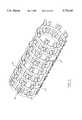
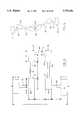
- FIG. 1is a side elevation of an assembled stent
- FIG. 2is a view on the line 2--2 of FIG. 1;
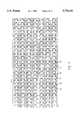
- FIG. 3is a developed view of the stent shown in FIG. 1;
- FIG. 4is a view on an enlarged scale of a portion of the stent shown in FIGS. 1-3;
- FIG. 5is a view of the portion of the stent shown in FIG. 4 after radial expansion
- FIG. 6is a view similar to FIG. 4 of an alternative embodiment of stent
- FIG. 7is a view of the embodiment of FIG. 6 after radial expansion
- FIG. 8is a further alternative of stent shown in FIG. 4;
- FIG. 9is a view of the embodiment of FIG. 8 after radial expansion
- FIG. 10is a comparative curve between the embodiments of stent shown in FIGS. 4, 6 and 8;
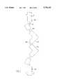
- FIG. 11is a perspective view of a further embodiment of stent.
- FIG. 12is a developed view of the embodiment of stent shown in FIG. 11;
- FIG. 13is an enlarged view of a portion of the stent shown in FIG. 11;
- FIG. 14is a view similar to FIG. 9 showing the stent after radial expansion
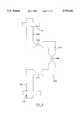
- FIG. 15is a sectional view of a stent support and catheter.
- FIG. 16is a developed view, similar to FIG. 12, of a further embodiment.
- a stent 10has a generally tubular body 12 which is initially dimensioned to permit insertion into a vessel such as an artery.
- the body 12includes a plurality of longitudinal struts 14 which are interconnected by multi-bar linkages 16.
- the linkages 16are regularly spaced along the axial extent of the struts 14 and maintain struts 14 in circumferentially spaced relationship.
- each of the linkages 16includes a pair of oppositely directed circumferential links 18 with axial links 20 connected to the circumferential links 18 and extending parallel to the struts 14 but spaced therefrom.
- the axial links 20are connected to an L-shaped corner link 22 which has an axial leg 24 and circumferential leg 26.
- the legs 26 of opposed corner links 22are interconnected by a circumferential connecting link 28 to interconnect the adjacent struts 14.
- the links 18, 20, 22 and 28 of the linkage 16are formed by removal of material from a seamless tube of bio-compatible material so that the links are integrally connected to one another.
- Such materialwould be a metal such as both pure and alloyed titanium, platinum, nitinol memory metals, gold or stainless steel, and the linkage may suitably be machined through micro machining techniques.
- Other materialscould be used that are considered suitable for implantation including plastics materials having the requisite properties.
- Each of the linkages 16is similar and the relative dimensions between the links in each linkage determine the change in diameter for a given load.
- the relative dimensions of the other links as indicated by the letters or FIG. 4are as follows:
- the stent 10is typically inserted into the vessel by using a balloon catheter 60.
- the stent 10is mounted on the catheter 60 shown in FIG. 15.
- the stentis initially located on a support 62 that has a bar-like head 64 and a tapered body 66.
- the stent 10is snugly received on the body 66 which has a concave recess 68 at one end to locate the tip of catheter 60.
- a bore 70extends through the body 66 to accomodate a wire if the catheter is of the type that employs such.
- a protective sleeve 72is located over the body 66 and is retained on a boss 74 on the head 64. The sleeve 72 thus protects the stent 10 from extraneous external forces with the body 66 providing support for the stent 10 in transit.
- the sleeve 72is removed and the body 66 is aligned with the catheter 60.
- the stentmay then be slid axially from the body 66 over the catheter 60 and the support and sleeve discarded. In this way, the stent is guided during transfer and the placement of the stent on the catheter facilitated.
- the recess 68assists in locating and aligning the catheter 60 during transfer and of course the wire, if present, may be fed through the bore 70.
- the stent 10is located on the body 66 such that the links 28 are closer to the boss 74 than the associated links 18. Transfer of the stent 10 to the catheter thus ensures that the stent 10 is oriented on the catheter 60 such that the connecting link 28 of the linkage 16 is in advance of the circumferential links 18 during insertion of the stent 10 into the vessel.
- the catheteris inserted into the vessel in a conventional manner until it is located at the stenosis.
- the catheterAfter placement within the vessel, the catheter is then inflated to apply a radially expanding force to the stent.
- the application of the radial forcecauses the circumferential spacing of struts 14 to increase.
- the circumferential links 18are carried with the struts 14 and a hinging action occurs at the connection of the axial link 20 to both the circumferential link 18 and the corner link 22 by plastic deformation of the links.
- the connecting link 28hinges at its connection to the corner link 22 to provide a hinging action between the links.
- the links 22is thus bodily rotated as the struts 14 are spread.
- the catheteris then deflated and removed, leaving the stent 10 in situ. It will be noted, however, that during inflation the struts 14 maintain the axial spacing between the circumferential links 18 so that the overall length of the stent remains the same with no relative axial movement between the vessel and the stent.
- linkage 16is shown in FIGS. 6 and 7, in which like components will be denoted with like reference numerals with a suffix ⁇ a ⁇ added for clarity.
- the circumferential link 18ais formed as a pair of rectangular nodes 30,32 interconnected by a narrow bar 34.
- the length of the axial link 20ais reduced to 0.5 of a unit value and a corresponding reduction in the length of the connecting link 28 to 0.5 is made.
- the application of the radial loadcauses the connection at the bar 34 to plastically deform, allowing rotation of the rectangular bar 32.
- the connecting link 28ais also subjected to bending load as well as plastic deformation at the connection to the links 22a.
- FIG. 8A further embodiment is seen in FIG. 8 where again like reference numerals will be used to denote like components with a suffix ⁇ b ⁇ added for clarity.
- the connection between the connecting links 20b and the circumferential links 18bprogressively tapers to the dimension F.
- the junction between the connecting link 28b and the link 22bprogressively tapers and in each case the overall length of the links 20b,28b is reduced from 1 unit value to 0.5 unit value.
- a tapering in the order of 45°is found to be appropriate.
- FIGS. 11-14offer enhanced flexibility for the stent during insertion, as may be needed to negotiate tight turns in the arterial system during placement, thereby minimizing damage to the arterial wall.
- each of the struts 14cis segmented so as to be comprised of either a series of unitary struts 40 or a series of linking struts 42.
- the unitary struts 40alternate with linking struts 42 about the circumference of stent 10c and in the preferred embodiment an even number of each Is provided so that the linking struts 42 are diametrically opposed. It is preferred that four linking struts 42 are provided and are circumferentially spaced at 90° intervals.
- Each of the unitary struts 40extend between two of the linkages 16c so as to interconnect them.
- the unitary strutsare spaced apart from one another by a gap indicated at 44 so that each linkage 16c is connected to only one of the adjacent linkages 16c.
- the linking struts 42extend between four of the linkages 16c and are then spaced from the next of the linking struts 42 by a space indicated at 46.
- the gaps 44 between the unitary strutsare circumferentially aligned to provide annular bands 48 whereas spaces 46 are staggered between alternate linking struts 42.
- Each of the linking struts 42has a waist 50 to provide a region of enhanced flexibility in a plane tangential to the surface of the stent 10c.
- the waist 50is aligned with one of the bands 48 and so provides the connection across the band 48 between the linkages 16c.
- the waists 50are located at diametrically opposed locations it the respective bank 48 to define a pair of pivot axes X--X.
- the waists 50are displaced by 90° in adjacent bands 48 so that the pivot axes X--X are disposed at 90°.
- This arrangementprovides flexibility about mutually perpendicular axially spaced axes allowing relative pivotal movement between sections of the stent to conform to the vessel into which it is inserted.
- the linkage 16cis shown in detail in FIG. 13 and includes circumferential links 18c and axial links 20c connected by a node 32c.
- the circumferential link 28cis connected to axial link 20c by corner link 22c which is formed as a rectangular leg 24c.
- the relative dimensionsare as follows:
- the fillets 52are each 0.125 and the thickness of the material between 0.0625 and 0.125.
- each band 48has two axial struts that inhibit relative axial movement between adjacent linkages 16c.
- the relatively flexible waists 50 disposed at 90° to one anotherprovides the requisite flexibility for insertion of the stent 10c.
- FIG. 11shows axes of rotation at 90° to one another
- alternative arrangementsmay be used by varying the relative orientation of the waisted links. For example, by spacing the links at 60° angles, three axes of rotation are obtained at axially spaced locations.
- linkage 16The following relative dimensions of linkage 16 have also been found to provide satisfactory performance:
- the unitsare 0.001 inches and the thickness of the material used was 0.003 inches.
- the width, ie. circumferential dimension, of the struts 14was 5 units and the axial spacing between adjacent linkages 16 was 12 units.
- Example IIthe width of the struts 14 was 2.85 units and the axial spacing between adjacent linkages was 3 units.
- the linkagesare repeated 4 times about the circumference.
- the diameter of the stent prior to expansionwas 65 units and after expansion with a 45° rotation of the links 20c an outside diameter of 197 units was obtained with Example II and 152.3 units with Example III.
- the axial spacing between linkages 16was sufficient to permit the bodily rotation of the corner links as the stent expands radially.
- the provision of the strut 14inhibits foreshortening and therefore ensures that the linkages can rotate as required.
- FIG. 16A further embodiment is shown in FIG. 16 in which like components will be identified with like reference numerals with a suffix ⁇ d ⁇ added for clarity.
- the embodiment of FIG. 16is similar to that shown in FIGS. 12 and 13.
- each of the struts 14dis segmented into a series of unitary struts 40d that extend between two adjacent linkages 16d.
- the struts 40dare staggered circumferentially to alternate the direction of connection between adjacent linkages.
- the unitary linkages 40dare thus aligned at diametrically opposed locations and thus define a pair of orthogonal axes at axially spaced locations to provide flexibility during insertion.
- the stentwill of course be dimensioned to fit within the intended vessel and engage the wall when extended.
- a typical stent for insertion in an arterywill have a diameter of between 1.5 mm and 3.5 mm when inserted and may have a diameter of between 2 mm and 12 mm when expanded.
Landscapes
- Health & Medical Sciences (AREA)
- Engineering & Computer Science (AREA)
- Biomedical Technology (AREA)
- Life Sciences & Earth Sciences (AREA)
- General Health & Medical Sciences (AREA)
- Cardiology (AREA)
- Oral & Maxillofacial Surgery (AREA)
- Transplantation (AREA)
- Heart & Thoracic Surgery (AREA)
- Vascular Medicine (AREA)
- Physics & Mathematics (AREA)
- Animal Behavior & Ethology (AREA)
- Optics & Photonics (AREA)
- Public Health (AREA)
- Veterinary Medicine (AREA)
- Media Introduction/Drainage Providing Device (AREA)
- Prostheses (AREA)
- Materials For Medical Uses (AREA)
- Hydrogenated Pyridines (AREA)
- Pharmaceuticals Containing Other Organic And Inorganic Compounds (AREA)
Abstract
Description
Expandable stents are widely used to provide local reinforcement in fluid-carrying vessels within the human body. The stent is essentially a cylindrical member which may be expanded radially to dilate the vessel and to provide support for the wall of the vessel to maintain it in the dilated condition.
In order to insert the stent, it has previously been proposed to place the stent into the vessel on an expandable or balloon catheter. With the stent positioned at the appropriate location, the catheter is inflated and the stent is caused to expand radially against the wall of the vessel. Once the stent is expanded to the required diameter, the catheter is deflated and may be removed, leaving the stent in position.
The stent must of course remain expanded against the wall of the vessel and should be capable of withstanding the forces imposed by the wall of the vessel. Moreover, the stent should be able to negotiate tight turns in the arterial system during placement while minimizing damage to the arterial wall.
A number of different mechanisms have been proposed to permit the expansion of the stent, including devices which reorient the components forming the stent so that they may adopt a greater overall diameter.
In another class of stents, as typified by the stent shown in U.S. Pat. No. 4,733,665 to Palmaz, the stent is configured to be plastically deformable so that after expansion it retains the increased diameter. In the Palmaz stent, the plastic deformation is provided by means of an open-mesh diamond structure. As the catheter is expanded, the intersecting members of the mesh deform so that the stent adopts an increased diameter.
With the arrangements shown in the Palmaz stent and similar configurations, a radial expansion of the stent is accompanied by an axial foreshortening of the stent. The degree of foreshortening is predictable but the ultimate location of the stent along the vessel is not predictable. Thus, one end of the stent may remain stationary relative to the blood vessel so that the opposite end is subjected to the maximum axial displacement or there may be progressive foreshortening from both ends with an intermediate location remaining stationary. The foreshortening of the stent leads to an unpredictable location for the stent in its expanded condition and induces relative movement in an axial direction between the vessel wall and the stent which is generally undesirable.
It is therefore an object of the present invention to provide a stent in which the above disadvantages are obviated or mitigated.
In general terms, the present invention provides a stent in which a plurality of circumferentially-spaced longitudinal struts are interconnected by multi-bar linkages. Adjacent links of the linkages are angularly disposed to one another such that a radial force causes relative rotation between adjacent links to permit radial enlargement of the stent. The longitudinal struts inhibit foreshortening of the stent so that the final location of the stent can be predicted.
Embodiments of the invention will now be described by way of example only with reference to the accompanying drawings, in which
FIG. 1 is a side elevation of an assembled stent;
FIG. 2 is a view on theline 2--2 of FIG. 1;
FIG. 3 is a developed view of the stent shown in FIG. 1;
FIG. 4 is a view on an enlarged scale of a portion of the stent shown in FIGS. 1-3;
FIG. 5 is a view of the portion of the stent shown in FIG. 4 after radial expansion;
FIG. 6 is a view similar to FIG. 4 of an alternative embodiment of stent;
FIG. 7 is a view of the embodiment of FIG. 6 after radial expansion;
FIG. 8 is a further alternative of stent shown in FIG. 4;
FIG. 9 is a view of the embodiment of FIG. 8 after radial expansion;
FIG. 10 is a comparative curve between the embodiments of stent shown in FIGS. 4, 6 and 8;
FIG. 11 is a perspective view of a further embodiment of stent;
FIG. 12 is a developed view of the embodiment of stent shown in FIG. 11;
FIG. 13 is an enlarged view of a portion of the stent shown in FIG. 11;
FIG. 14 is a view similar to FIG. 9 showing the stent after radial expansion;
FIG. 15 is a sectional view of a stent support and catheter; and
FIG. 16 is a developed view, similar to FIG. 12, of a further embodiment.
Referring therefore to FIG. 1, astent 10 has a generallytubular body 12 which is initially dimensioned to permit insertion into a vessel such as an artery. Thebody 12 includes a plurality oflongitudinal struts 14 which are interconnected bymulti-bar linkages 16. Thelinkages 16 are regularly spaced along the axial extent of thestruts 14 and maintainstruts 14 in circumferentially spaced relationship.
As can best be seen in FIG. 4, each of thelinkages 16 includes a pair of oppositely directedcircumferential links 18 withaxial links 20 connected to thecircumferential links 18 and extending parallel to thestruts 14 but spaced therefrom.. Theaxial links 20 are connected to an L-shaped corner link 22 which has anaxial leg 24 and circumferential leg 26. The legs 26 ofopposed corner links 22 are interconnected by acircumferential connecting link 28 to interconnect theadjacent struts 14. Thelinks linkage 16 are formed by removal of material from a seamless tube of bio-compatible material so that the links are integrally connected to one another. Typically such material would be a metal such as both pure and alloyed titanium, platinum, nitinol memory metals, gold or stainless steel, and the linkage may suitably be machined through micro machining techniques. Other materials could be used that are considered suitable for implantation including plastics materials having the requisite properties.
Each of thelinkages 16 is similar and the relative dimensions between the links in each linkage determine the change in diameter for a given load. In a typical example, as shown in FIG. 4, taking the length of the connectinglink 28 to be of unit length, then the relative dimensions of the other links as indicated by the letters or FIG. 4 are as follows:
______________________________________ a b c d e f g h i j k ______________________________________ 1 2 1 0.625 1.125 0.125 2.125 2.0 1.375 1.125 0.125 ______________________________________
Thestent 10 is typically inserted into the vessel by using aballoon catheter 60. Thestent 10 is mounted on thecatheter 60 shown in FIG. 15. To assist in placement of thestent 10 on thecatheter 60, the stent is initially located on a support 62 that has a bar-like head 64 and a tapered body 66. Thestent 10 is snugly received on the body 66 which has aconcave recess 68 at one end to locate the tip ofcatheter 60. Abore 70 extends through the body 66 to accomodate a wire if the catheter is of the type that employs such.
Aprotective sleeve 72 is located over the body 66 and is retained on aboss 74 on thehead 64. Thesleeve 72 thus protects thestent 10 from extraneous external forces with the body 66 providing support for thestent 10 in transit.
To transfer the stent to thecatheter 60, thesleeve 72 is removed and the body 66 is aligned with thecatheter 60. The stent may then be slid axially from the body 66 over thecatheter 60 and the support and sleeve discarded. In this way, the stent is guided during transfer and the placement of the stent on the catheter facilitated.
Therecess 68 assists in locating and aligning thecatheter 60 during transfer and of course the wire, if present, may be fed through thebore 70.
Thestent 10 is located on the body 66 such that thelinks 28 are closer to theboss 74 than the associatedlinks 18. Transfer of thestent 10 to the catheter thus ensures that thestent 10 is oriented on thecatheter 60 such that the connectinglink 28 of thelinkage 16 is in advance of thecircumferential links 18 during insertion of thestent 10 into the vessel.
The catheter is inserted into the vessel in a conventional manner until it is located at the stenosis.
After placement within the vessel, the catheter is then inflated to apply a radially expanding force to the stent.
As shown in FIG. 5, the application of the radial force causes the circumferential spacing ofstruts 14 to increase. Thecircumferential links 18 are carried with thestruts 14 and a hinging action occurs at the connection of theaxial link 20 to both thecircumferential link 18 and thecorner link 22 by plastic deformation of the links. Similarly, the connectinglink 28 hinges at its connection to thecorner link 22 to provide a hinging action between the links. Thelinks 22 is thus bodily rotated as thestruts 14 are spread.
By virtue of the relativelynarrow links larger links axial links 20 and circumferential link 28 is distributed between two locations.
The catheter is then deflated and removed, leaving thestent 10 in situ. It will be noted, however, that during inflation thestruts 14 maintain the axial spacing between thecircumferential links 18 so that the overall length of the stent remains the same with no relative axial movement between the vessel and the stent.
In tests with samples of the configuration of FIGS. 4 and 5, an extension from the spacing of thestruts 14 was increased from an initial value of 6 units to 8.48 units upon application of loads consistent with those used in the expansion of such stents.
An alternative embodiment oflinkage 16 is shown in FIGS. 6 and 7, in which like components will be denoted with like reference numerals with a suffix `a` added for clarity.
In the embodiment of FIG. 6, thecircumferential link 18a is formed as a pair ofrectangular nodes narrow bar 34. The length of theaxial link 20a is reduced to 0.5 of a unit value and a corresponding reduction in the length of the connectinglink 28 to 0.5 is made. As may be seen in FIG. 7, the application of the radial load causes the connection at thebar 34 to plastically deform, allowing rotation of therectangular bar 32. The connectinglink 28a is also subjected to bending load as well as plastic deformation at the connection to thelinks 22a.
In tests conducted with samples of the arrangements shown in FIGS. 6 and 7, the initial spacing of thestruts 14 was increased to 8.5 units after application of a radial force consistent with that found in balloon catheters.
A further embodiment is seen in FIG. 8 where again like reference numerals will be used to denote like components with a suffix `b` added for clarity. In the embodiment of FIG. 8, the connection between the connectinglinks 20b and thecircumferential links 18b progressively tapers to the dimension F. In a similar manner, the junction between the connectinglink 28b and thelink 22b progressively tapers and in each case the overall length of thelinks
The results of tests conducted on the embodiment shown in FIGS. 4, 6 and 8 are represented on the curve of FIG. 10. This curve represents the applied radial load and the deflection obtained and it will be seen that in each embodiment there is an initial proportional increase of load and deflection followed by a much flatter curve indicating a plastic deformation. Thereafter, the load progressively increases, indicating that the orientation of the links is approaching a linear orientation. It will be seen that the embodiment of FIG. 8 provides a lower load to achieve the requisite deflections. With the provision of the relatively narrow links, it is possible to control the radial force necessary to expand the stent and the location at which the bending will occur. The force necessary to achieve radial expansion must be compatible with the forces available from a balloon catheter and the reduced width of the links permits this. Moreover, the plastic deformation of the narrow links maintains control of the orientation of the wider links during expansion.
A further embodiment is shown in FIGS. 11-14 offering enhanced flexibility for the stent during insertion, as may be needed to negotiate tight turns in the arterial system during placement, thereby minimizing damage to the arterial wall.
In the embodiment of FIGS. 11-14, in which like components are denoted with like numerals with a suffic "c" added for clarity, each of thestruts 14c is segmented so as to be comprised of either a series ofunitary struts 40 or a series of linking struts 42.
The unitary struts 40 alternate with linkingstruts 42 about the circumference of stent 10c and in the preferred embodiment an even number of each Is provided so that the linking struts 42 are diametrically opposed. It is preferred that four linkingstruts 42 are provided and are circumferentially spaced at 90° intervals.
Each of theunitary struts 40 extend between two of the linkages 16c so as to interconnect them. The unitary struts are spaced apart from one another by a gap indicated at 44 so that each linkage 16c is connected to only one of the adjacent linkages 16c. By contrast, the linking struts 42 extend between four of the linkages 16c and are then spaced from the next of the linking struts 42 by a space indicated at 46.
The gaps 44 between the unitary struts are circumferentially aligned to provideannular bands 48 whereasspaces 46 are staggered between alternate linking struts 42. Each of the linking struts 42 has awaist 50 to provide a region of enhanced flexibility in a plane tangential to the surface of the stent 10c. Thewaist 50 is aligned with one of thebands 48 and so provides the connection across theband 48 between the linkages 16c.
As can be seen in FIG. 11, thewaists 50 are located at diametrically opposed locations it therespective bank 48 to define a pair of pivot axes X--X. By virtue of the staggered relationship between adjacent linking struts 42, thewaists 50 are displaced by 90° inadjacent bands 48 so that the pivot axes X--X are disposed at 90°.
This arrangement provides flexibility about mutually perpendicular axially spaced axes allowing relative pivotal movement between sections of the stent to conform to the vessel into which it is inserted.
The linkage 16c is shown in detail in FIG. 13 and includescircumferential links 18c andaxial links 20c connected by anode 32c.
Thecircumferential link 28c is connected toaxial link 20c bycorner link 22c which is formed as arectangular leg 24c.
It will be noted that the connection of each of thelinks struts 14c,nodes 32c andcorner link 22c by radiused fillets 52 that reduce local stress concentrations.
In one preferred example, the relative dimensions are as follows:
______________________________________ a b c d e f g h i ______________________________________ 1.20 0.75 1.40 1.40 2.00 0.90 0.25 6.9 5.30 ______________________________________
The fillets 52 are each 0.125 and the thickness of the material between 0.0625 and 0.125.
With this configuration, the application of a radial load results in the circumferential expansion shown in FIG. 14 from which it can be seen that a uniform bending of thelinks 18c is obtained and that theaxial links 20 have assumed a circumferential orientation.
Upon circumferential expansion, the linking struts 42 inhibit foreshortening as eachband 48 has two axial struts that inhibit relative axial movement between adjacent linkages 16c. At the same time the relativelyflexible waists 50 disposed at 90° to one another provides the requisite flexibility for insertion of the stent 10c.
Although the embodiment of FIG. 11 shows axes of rotation at 90° to one another, alternative arrangements may be used by varying the relative orientation of the waisted links. For example, by spacing the links at 60° angles, three axes of rotation are obtained at axially spaced locations.
The following relative dimensions oflinkage 16 have also been found to provide satisfactory performance:
Example I:
______________________________________ a b c d e f g h i ______________________________________ 10 7.5 11 17.8 38.6 12.3 3 46 74.2 ______________________________________
Example II:
______________________________________ a b c d e f g h i ______________________________________ 10.3 7.7 12.2 17.8 38.6 12.3 3 48.2 74.2 ______________________________________
Example III:
______________________________________ a b c d e f g h i ______________________________________ 10.0 7.5 11 14.3 20.4 9.2 3 46 49 ______________________________________
In each of these examples, the units are 0.001 inches and the thickness of the material used was 0.003 inches.
In Examples I and III, the width, ie. circumferential dimension, of thestruts 14 was 5 units and the axial spacing betweenadjacent linkages 16 was 12 units.
In Example II, the width of thestruts 14 was 2.85 units and the axial spacing between adjacent linkages was 3 units.
In each case, the linkages are repeated 4 times about the circumference. The diameter of the stent prior to expansion was 65 units and after expansion with a 45° rotation of thelinks 20c an outside diameter of 197 units was obtained with Example II and 152.3 units with Example III. The axial spacing betweenlinkages 16 was sufficient to permit the bodily rotation of the corner links as the stent expands radially. The provision of thestrut 14 inhibits foreshortening and therefore ensures that the linkages can rotate as required.
A further embodiment is shown in FIG. 16 in which like components will be identified with like reference numerals with a suffix `d` added for clarity. The embodiment of FIG. 16 is similar to that shown in FIGS. 12 and 13. However, each of the struts 14d is segmented into a series of unitary struts 40d that extend between two adjacent linkages 16d. The struts 40d are staggered circumferentially to alternate the direction of connection between adjacent linkages. The unitary linkages 40d are thus aligned at diametrically opposed locations and thus define a pair of orthogonal axes at axially spaced locations to provide flexibility during insertion.
The stent will of course be dimensioned to fit within the intended vessel and engage the wall when extended. A typical stent for insertion in an artery will have a diameter of between 1.5 mm and 3.5 mm when inserted and may have a diameter of between 2 mm and 12 mm when expanded.
Claims (61)
1. A stent having a generally tubular body with a plurality of circumferentially spaced longitudinal struts extending parallel to a longitudinal axis of said body, circumferentially adjacent pairs of said struts being interconnected solely by a set of linkages axially spaced from one another and each including a plurality of links connected to one another, adjacent links of said linkages being angularly disposed relative to one another such that a radial force causes relative rotation between adjacent links and plastic deformation thereof to permit radial expansion of said stent, said struts inhibiting relative axial movement between said linkages and foreshortening of said body and said struts remaining in substantially parallel relationship with said longitudinal axis upon radial expansion of said stent and wherein all of said sets of linkages are unidirectionally facing with one of said links of each linkage being offset axially from the connection of said linkage to said struts in a common direction.
2. A stent according to claim 1 wherein each of said linkages comprises an opposing pair of first circumferentially extending links connected at one end to said struts and connected at an opposite end to axially extending links, said axially extending links being connected to each other by a second circumferentially extending link axially spaced from said first circumferentially extending links.
3. A stent according to claim 2 wherein the intersection of at least one pair of adjacent links of each of said linkages has a zone of relative weakness adjacent to but spaced from said intersection to provide a pair of spaced hinge points, whereby relative rotation between said at least one pair of links is distributed between said hinge points.
4. A stent according to claim 2 wherein said first circumferentially extending links and said axially extending links are enlarged at their intersections to provide a pair of spaced hinges at each connection thereof.
5. A stent according to claim 4 wherein said axially extending links and said second circumferentially extending link are enlarged at their intersections to provide a pair of spaced hinges at each connection thereof.
6. A stent according to claim 2 wherein said axially extending links are perpendicular to said first and second circumferentially extending links.
7. A stent according to claim 1 wherein each of said struts extends between at least two axially adjacent linkages.
8. A stent according to claim 7 wherein selected ones of said struts are discontinuous thereby providing a plurality of gaps along the length thereof, the axial location of said gaps being staggered about the circumference of said body whereby relative axial movement between said linkages is inhibited by struts circumferentially spaced from and axially aligned with said gaps.
9. A stent according to claim 8 wherein said struts axially aligned with said gaps are reduced in section to facilitate flexure thereof.
10. A stent according to claim 9 wherein struts having a reduced section are diametrically aligned to provide pivot axes of relative pivotal movement between said adjacent linkages.
11. A stent according to claim 10 wherein said pivot axes are angularly disposed relative to one another.
12. A stent according to claim 11 wherein said axes are disposed at 90° to one another.
13. A stent according to claim 10 wherein said axially extending links and said first and second circumferentially extending links are enlarged at their intersections to provide pairs of spaced hinges at each connection thereof.
14. A stent according to claim 13 wherein said enlarged intersections are generally rectangular.
15. A stent having a generally tubular body with a plurality of circumferentially spaced longitudinal struts extending parallel to a longitudinal axis of said body, circumferentially adjacent pairs of said struts being interconnected by a plurality of linkages axially spaced from one another and each including a plurality of links connected to one another, adjacent links of said linkages being angularly disposed relative to one another such that a radial force causes relative rotation between adjacent links and plastic deformation thereof to permit radial expansion of said stent, said struts inhibiting relative axial movement between said linkages and foreshortening of said body wherein each of said linkages comprises an opposing pair of first circumferentially extending links connected at one end to said struts and connected at an opposite end to axially extending links, said axially extending links being connected to each other by a second circumferentially extending link axially spaced from said first circumferentially extending links, and wherein said axially extending links and said first and second circumferentially extending links are enlarged at their intersections to provide pairs of spaced hinges at each connection thereof.
16. A stent according to claim 15 wherein said axially extending links are perpendicular to said first and second circumferentially extending links.
17. A stent according to claim 16 wherein said enlarged intersections are generally rectangular.
18. A stent according to claim 17 wherein each of said struts extends between at least two axially adjacent linkages.
19. A stent according to claim 18 wherein selected ones of said struts are discontinuous thereby providing a plurality of gaps along the length thereof, the axial location of said gaps being staggered about the circumference of said body whereby relative axial movement between said linkages is inhibited by struts circumferentially spaced from and axially aligned with said gaps.
20. A stent according to claim 19 wherein said struts axially aligned with said gaps are reduced in section to facilitate flexure thereof.
21. A stent according to claim 20 wherein struts having a reduced section are diametrically aligned to provide pivot axes of relative pivotal movement between said adjacent linkages.
22. A stent according to claim 21 wherein said pivot axes are angularly disposed relative to one another.
23. A stent according to claim 22 wherein said axes are disposed at 90° to one another.
24. A stent having a generally tubular body with a plurality of circumferentially spaced longitudinal struts extending along the entire length of and parallel to a longitudinal axis of said body, circumferentially adjacent pairs of said struts being interconnected by a plurality of linkages axially spaced from one another and each including a plurality of links connected to one another, adjacent links of said linkages being angularly disposed relative to one another such that a radial force causes relative rotation between adjacent links and plastic deformation thereof to permit radial expansion of said stent, said struts inhibiting relative axial movement between said linkages and foreshortening of said body, wherein selected ones of said struts are discontinuous thereby providing a plurality of gaps along the length thereof, the axial location of said gaps being staggered about the circumference of said body whereby relative axial movement between said linkages is inhibited by struts circumferentially spaced from and axially aligned with said gaps, and wherein selected ones of said struts have a reduced cross-section and are arranged such that a gap and a strut with a reduced cross-section lie in a common plane orthogonal to the longitudinal axis of said body.
25. A stent according to claim 24 wherein struts having a reduced section are diametrically aligned to provide pivot axes of relative pivotal movement between said adjacent linkages.
26. A stent according to claim 25 wherein said pivot axes are angularly disposed relative to one another.
27. A stent according to claim 26 wherein said axes are disposed at 90° to one another.
28. A stent according to claim 27 wherein each of said linkages comprises an opposing pair of first circumferentially extending links connected at one end to said struts and connected at an opposite end to axially extending links, said axially extending links being connected to each other by a second circumferentially extending link axially spaced from said first circumferentially extending links.
29. A stent according to claim 28 wherein said axially extending links and said first and second circumferentially extending links are enlarged at their intersections to provide pairs of spaced hinges at each connection thereof.
30. A stent according to claim 29 wherein each of said struts extends between at least two axially adjacent linkages.
31. A stent according to claim 30 wherein said axially extending links are perpendicular to said first and second circumferentially extending links.
32. A stent according to claim 31 wherein said enlarged intersections are generally rectangular.
33. A stent having a generally tubular body with a plurality of circumferentially spaced longitudinal struts extending parallel to a longitudinal axis of said body, circumferentially adjacent pairs of said struts being interconnected by a plurality of linkages axially spaced from one another and each including a plurality of links connected to one another, adjacent links of said linkages being angularly disposed relative to one another such that a radial force causes relative rotation between adjacent links and plastic deformation thereof to permit radial expansion of said stent, said struts inhibiting relative axial movement between said linkages and foreshortening of said body and said struts remaining in parallel relationship with said longitudinal axis upon radial expansion of said stent and wherein the intersection of at least one pair of adjacent links of each said linkages has a zone of relative weakness adjacent to but spaced from said intersection to provide a pair of spaced hinge points, whereby relative rotation between said at least one pair of links is distributed between said hinge points.
34. A stent as claimed in claim 33 wherein said intersection of at least one pair of links comprises an enlarged node.
35. A stent as claimed in claim 34 wherein said enlarged node is rectangular.
36. A stent having a generally tubular body with a plurality of circumferentially spaced longitudinal struts extending parallel to a longitudinal axis of said body, circumferentially adjacent pairs of said struts being interconnected by a plurality of linkages axially spaced from one another and each including a plurality of links connected to one another, adjacent links of said linkages being angularly disposed relative to one another such that a radial force causes relative rotation between adjacent links and plastic deformation thereof to permit radial expansion of said stent, said struts inhibiting relative axial movement between said linkages and foreshortening of said body, wherein selected ones of said struts are discontinuous thereby providing a plurality of gaps along the length thereof, the axial location of said gaps being staggered about the circumference of said body whereby relative axial movement between said linkages is inhibited by struts circumferentially spaced from and axially aligned with said gaps, and wherein said gaps are configured to provide only a pair of diametrically aligned struts at selected ones of said axial locations to facilitate flexure of said stent.
37. A stent as claimed in claim 36 wherein said pairs of diametrically aligned struts provide pivot axes of relative pivotal movement between said adjacent linkages.
38. A stent according to claim 37 wherein said pivot axes are angularly disposed relative to one another.
39. A stent according to claim 38 wherein said axes are disposed at 90° to one another.
40. A stent as claimed in claim 39 wherein said diametrically aligned struts are reduced in section.
41. A stent having a generally tubular body with a plurality of circumferentially spaced longitudinal struts extending parallel to a longitudinal axis of said body, circumferentially adjacent pairs of said struts being interconnected solely by a set of linkages axially spaced from one another and defining a predetermined space between adjacent pairs of said struts, all of said sets of linkages being unidirectionally facing and each having a plurality of links angularly disposed relative to one another in an unexpanded condition such that when a radial force is exerted on said tubular body, relative rotation between adjacent links and plastic deformation occurs, thereby increasing said space between said adjacent pairs of sad struts and permitting radial expansion of said stent, said struts inhibiting relative axial movement between said linkages and foreshortening of said body.
42. A stent according to claim 41 wherein each of said linkages includes hinge points spaced apart along said linkage, said hinge points deforming upon radial expansion of said stent to facilitate relative rotation of said links.
43. A stent according to claim 42 wherein said hinge points are provided by zones of relative weakness along said links.
44. A stent according to claim 43 wherein said zones of relative weakness are located adjacent an intersection of adjacent links.
45. A stent according to claim 44 wherein said linkage includes a pair of spaced axial links connected at one end to respective ones of said struts and interconnected at an opposite end by a first circumferential link.
46. A stent according to claim 45 wherein said axial links are perpendicular to said circumferential link in said unexpanded condition.
47. A stent according to claim 46 wherein said axial links are connected to respective ones of said struts by second circumferential links.
48. A stent according to claim 45 wherein said first circumferential link and said axial links intersect at an enlarged node to provide a pair of spaced hinge points adjacent to said node.
49. A stent according to claim 45 wherein opposite ends of said axial link are connected to adjacent links by an enlarged node to provide a pair of spaced hinge points on said axial link.
50. A stent according to claim 45 wherein said first circumferential link is connected at opposite ends to respective axial links by an enlarged node to provide a pair of spaced hinge points on said first circumferential link.
51. A stent having a generally tubular body with a plurality of circumferentially spaced longitudinal struts extending parallel to a longitudinal axis of said body, circumferentially adjacent pairs of said struts being interconnected by a plurality of linkages, each of said linkages having a plurality of links angularly disposed relative to one another and including a pair of axially extending links connected to respective ones of said struts and interconnected to one another at a location spaced axially from their respective connections to said struts, said linkage including at least a pair of links having a portion of reduced cross-section to provide at least three hinge points spaced apart along said linkage and disposed to permit rotation of each of said axially extending links relative to said struts upon application of a radial load to said stent.
52. A stent according to claim 51 wherein said axially extending links are interconnected by a circumferentially extending link.
53. A stent according to claim 52 wherein said circumferentially extending link has a portion of reduced cross-section to provide a pair of circumferentially spaced hinge points adjacent to respective ones of said axial links.
54. A stent according to claim 51 wherein said axially extending links are connected to respective ones of said struts by one of a pair of circumferentially extending links.
55. A stent according to claim 54 wherein said axially extending links are interconnected by a circumferentially extending link.
56. A stent according to claim 55 wherein each of said circumferentially extending links includes a portion of reduced cross-section to provide a pair of spaced hinge points on each of said circumferentially spaced links.
57. A stent according to claim 56 wherein each of said axially extending links includes a portion of reduced cross-section.
58. A stent having a generally tubular body with a plurality of circumferentially spaced longitudinal struts extending parallel to a longitudinal axis of said body, circumferentially adjacent pairs of said struts being interconnected by a plurality of linkages, each of said linkages having a plurality of links angularly disposed relative to one another and including a pair of axially extending links connected to respective ones of said struts and interconnected to one another by a circumferentially extending link, at least a portion of said circumferentially extending link having a reduced cross-section to provide a pair of circumferentially spaced hinge points which, in conjunction with an additional pair of hinge points disposed on said linkage, permit rotation of said axially extending links relative to said circumferentially extending link upon application of a radial load to said body to expand said body.
59. A stent according to claim 58 wherein said additional pair of hinge points is located on respective ones of said axially extending links.
60. A stent according to claim 59 wherein each of said axially extending links has a pair of spaced hinge points formed thereon.
61. A stent according to claim 58 wherein said hinge points plastically deform upon application of a radial load to maintain said body in an expanded condition.
Priority Applications (2)
| Application Number | Priority Date | Filing Date | Title |
|---|---|---|---|
| US09/063,496US6261318B1 (en) | 1995-07-25 | 1998-04-20 | Expandable stent |
| US10/759,527US20050060024A1 (en) | 1995-07-25 | 2004-01-20 | Expandible stent |
Applications Claiming Priority (4)
| Application Number | Priority Date | Filing Date | Title |
|---|---|---|---|
| GB9515282 | 1995-07-25 | ||
| GBGB9515282.3AGB9515282D0 (en) | 1995-07-25 | 1995-07-25 | Expandable stent |
| GBGB9605486.1AGB9605486D0 (en) | 1996-03-15 | 1996-03-15 | Flexible expandable stent |
| GB9605486 | 1996-03-15 |
Related Child Applications (1)
| Application Number | Title | Priority Date | Filing Date |
|---|---|---|---|
| US09/063,496Continuation-In-PartUS6261318B1 (en) | 1995-07-25 | 1998-04-20 | Expandable stent |
Publications (1)
| Publication Number | Publication Date |
|---|---|
| US5776181Atrue US5776181A (en) | 1998-07-07 |
Family
ID=26307463
Family Applications (1)
| Application Number | Title | Priority Date | Filing Date |
|---|---|---|---|
| US08/687,223Expired - Fee RelatedUS5776181A (en) | 1995-07-25 | 1996-07-25 | Expandable stent |
Country Status (17)
| Country | Link |
|---|---|
| US (1) | US5776181A (en) |
| EP (1) | EP0840578B1 (en) |
| JP (1) | JPH11509754A (en) |
| KR (1) | KR100452916B1 (en) |
| CN (1) | CN1208101C (en) |
| AT (1) | ATE352267T1 (en) |
| AU (1) | AU716536B2 (en) |
| BR (1) | BR9609817A (en) |
| CA (1) | CA2227754C (en) |
| DE (1) | DE69636867T2 (en) |
| HU (1) | HU221910B1 (en) |
| IL (1) | IL123039A (en) |
| MX (1) | MX9800714A (en) |
| NO (1) | NO314337B1 (en) |
| NZ (1) | NZ313115A (en) |
| PL (1) | PL184769B1 (en) |
| WO (1) | WO1997004721A1 (en) |
Cited By (93)
| Publication number | Priority date | Publication date | Assignee | Title |
|---|---|---|---|---|
| US6027527A (en)* | 1996-12-06 | 2000-02-22 | Piolax Inc. | Stent |
| US6179868B1 (en)* | 1998-03-27 | 2001-01-30 | Janet Burpee | Stent with reduced shortening |
| US6187035B1 (en)* | 1997-07-16 | 2001-02-13 | Yang-Soo Jang | Vascular stent |
| US6241760B1 (en)* | 1996-04-26 | 2001-06-05 | G. David Jang | Intravascular stent |
| US6241762B1 (en)* | 1998-03-30 | 2001-06-05 | Conor Medsystems, Inc. | Expandable medical device with ductile hinges |
| US6273909B1 (en) | 1998-10-05 | 2001-08-14 | Teramed Inc. | Endovascular graft system |
| US6280466B1 (en) | 1999-12-03 | 2001-08-28 | Teramed Inc. | Endovascular graft system |
| US6309414B1 (en)* | 1997-11-04 | 2001-10-30 | Sorin Biomedica Cardio S.P.A. | Angioplasty stents |
| US20020049493A1 (en)* | 1996-04-26 | 2002-04-25 | Jang G. David | Intravascular stent |
| US20020068969A1 (en)* | 2000-10-16 | 2002-06-06 | Shanley John F. | Expandable medical device with improved spatial distribution |
| US20020107563A1 (en)* | 2001-02-05 | 2002-08-08 | Shanley John F. | Expandable medical device with locking mechanism |
| US6432127B1 (en) | 1996-10-11 | 2002-08-13 | Transvascular, Inc. | Devices for forming and/or maintaining connections between adjacent anatomical conduits |
| US20020138129A1 (en)* | 1999-01-22 | 2002-09-26 | Armstrong Joseph R. | Method of producing low profile stent and graft combination |
| US20030040791A1 (en)* | 2001-08-22 | 2003-02-27 | Oktay Hasan Semih | Flexible MEMS actuated controlled expansion stent |
| US6527799B2 (en) | 1998-10-29 | 2003-03-04 | Conor Medsystems, Inc. | Expandable medical device with ductile hinges |
| US20030055487A1 (en)* | 2001-09-18 | 2003-03-20 | Jomed Nv | Stent |
| US20030074052A1 (en)* | 1997-01-24 | 2003-04-17 | Jomed Gmbh | Bistable spring construction for a stent and other medical apparatus |
| US6613081B2 (en) | 1997-11-14 | 2003-09-02 | Transvascular, Inc. | Deformable scaffolding multicellular stent |
| US6679910B1 (en) | 1999-11-12 | 2004-01-20 | Latin American Devices Llc | Intraluminal stent |
| US20040122506A1 (en)* | 2000-10-16 | 2004-06-24 | Conor Medsystems, Inc. | Expandable medical device for delivery of beneficial agent |
| US20040127976A1 (en)* | 2002-09-20 | 2004-07-01 | Conor Medsystems, Inc. | Method and apparatus for loading a beneficial agent into an expandable medical device |
| US6776791B1 (en) | 1998-04-01 | 2004-08-17 | Endovascular Technologies, Inc. | Stent and method and device for packing of same |
| US6805706B2 (en) | 2002-08-15 | 2004-10-19 | Gmp Cardiac Care, Inc. | Stent-graft with rails |
| US20040236408A1 (en)* | 1998-03-30 | 2004-11-25 | Conor Medsystems, Inc. | Expandable medical device for delivery of beneficial agent |
| US20050004651A1 (en)* | 1998-09-05 | 2005-01-06 | Abbott Laboratories Vascular Enterprises Limited | Methods and apparatus for a stent having an expandable web structure and delivery system |
| US20050015135A1 (en)* | 1999-05-20 | 2005-01-20 | Conor Medsystems, Inc. | Expandable medical device delivery system and method |
| US20050060024A1 (en)* | 1995-07-25 | 2005-03-17 | Lee J. Michael | Expandible stent |
| US20050234503A1 (en)* | 1998-09-25 | 2005-10-20 | Ravenscroft Adrian C | Removeable embolus blood clot filter and filter delivery unit |
| USD516723S1 (en) | 2004-07-06 | 2006-03-07 | Conor Medsystems, Inc. | Stent wall structure |
| US20060079956A1 (en)* | 2004-09-15 | 2006-04-13 | Conor Medsystems, Inc. | Bifurcation stent with crushable end and method for delivery of a stent to a bifurcation |
| US7056338B2 (en) | 2003-03-28 | 2006-06-06 | Conor Medsystems, Inc. | Therapeutic agent delivery device with controlled therapeutic agent release rates |
| US20060149352A1 (en)* | 2002-11-13 | 2006-07-06 | Biotronik Gmbh & Co. Kg | Bearing structure |
| US20060175727A1 (en)* | 2001-09-28 | 2006-08-10 | Abbott Laboratories Vascular Enterprises Limited | Porous membranes for medical implants and methods of manufacture |
| US7112217B1 (en) | 1998-03-16 | 2006-09-26 | Cordis Corporation | Biluminal endovascular graft system |
| US20060217795A1 (en)* | 1997-01-24 | 2006-09-28 | Paragon Intellectual Properties, Llc | Fracture-resistant helical stent incorporating bistable cells and methods of use |
| US20060241739A1 (en)* | 1997-01-24 | 2006-10-26 | Paragon Intellectual Properties, Llc | Device comprising biodegradable bistable or multistable cells and methods of use |
| US7169179B2 (en) | 2003-06-05 | 2007-01-30 | Conor Medsystems, Inc. | Drug delivery device and method for bi-directional drug delivery |
| US7208011B2 (en) | 2001-08-20 | 2007-04-24 | Conor Medsystems, Inc. | Implantable medical device with drug filled holes |
| US20070244543A1 (en)* | 2006-04-18 | 2007-10-18 | Medtronic Vascular, Inc. A Delaware Corporation | Stent With Movable Crown |
| US20080097579A1 (en)* | 2006-10-18 | 2008-04-24 | Conor Medsystems, Inc. | Stent with flexible hinges |
| US20090131970A1 (en)* | 2005-08-09 | 2009-05-21 | C.R. Bard Inc. | Embolus blood clot filter and delivery system |
| US7766956B2 (en) | 2000-09-22 | 2010-08-03 | Boston Scientific Scimed, Inc. | Intravascular stent and assembly |
| US7811314B2 (en) | 1998-09-05 | 2010-10-12 | Abbott Laboratories Vascular Enterprises Limited | Methods and apparatus for stenting comprising enhanced embolic protection coupled with improved protections against restenosis and thrombus formation |
| US7850726B2 (en) | 2007-12-20 | 2010-12-14 | Abbott Laboratories Vascular Enterprises Limited | Endoprosthesis having struts linked by foot extensions |
| US7887578B2 (en) | 1998-09-05 | 2011-02-15 | Abbott Laboratories Vascular Enterprises Limited | Stent having an expandable web structure |
| US8016874B2 (en) | 2007-05-23 | 2011-09-13 | Abbott Laboratories Vascular Enterprises Limited | Flexible stent with elevated scaffolding properties |
| US20110224781A1 (en)* | 2008-07-21 | 2011-09-15 | White Jennifer K | Repositionable endoluminal support structure and its applications |
| US8128679B2 (en) | 2007-05-23 | 2012-03-06 | Abbott Laboratories Vascular Enterprises Limited | Flexible stent with torque-absorbing connectors |
| US8197881B2 (en) | 2003-09-22 | 2012-06-12 | Conor Medsystems, Inc. | Method and apparatus for loading a beneficial agent into an expandable medical device |
| US8230913B2 (en) | 2001-01-16 | 2012-07-31 | Halliburton Energy Services, Inc. | Expandable device for use in a well bore |
| EP2489337A1 (en) | 2011-02-18 | 2012-08-22 | Cook Medical Technologies LLC | Prosthesis and method of manufacture |
| US8337544B2 (en) | 2007-12-20 | 2012-12-25 | Abbott Laboratories Vascular Enterprises Limited | Endoprosthesis having flexible connectors |
| US8349390B2 (en) | 2002-09-20 | 2013-01-08 | Conor Medsystems, Inc. | Method and apparatus for loading a beneficial agent into an expandable medical device |
| US8361537B2 (en) | 1998-03-30 | 2013-01-29 | Innovational Holdings, Llc | Expandable medical device with beneficial agent concentration gradient |
| US8372109B2 (en) | 2004-08-04 | 2013-02-12 | C. R. Bard, Inc. | Non-entangling vena cava filter |
| US8449901B2 (en) | 2003-03-28 | 2013-05-28 | Innovational Holdings, Llc | Implantable medical device with beneficial agent concentration gradient |
| US8535380B2 (en) | 2010-05-13 | 2013-09-17 | Stout Medical Group, L.P. | Fixation device and method |
| US8562665B2 (en) | 1998-02-02 | 2013-10-22 | Boston Scientific Scimed, Inc. | Tubular stent consists of chevron-shape expansion struts and contralaterally attached diagonal-connectors |
| US8574261B2 (en) | 2005-05-12 | 2013-11-05 | C. R. Bard, Inc. | Removable embolus blood clot filter |
| US8613754B2 (en) | 2005-05-12 | 2013-12-24 | C. R. Bard, Inc. | Tubular filter |
| CN101594839B (en)* | 2006-10-18 | 2013-12-25 | 革新控股有限责任公司 | Brackets with flexible hinges |
| US8709042B2 (en) | 2004-09-21 | 2014-04-29 | Stout Medical Group, LP | Expandable support device and method of use |
| USRE45011E1 (en) | 2000-10-20 | 2014-07-15 | Halliburton Energy Services, Inc. | Expandable tubing and method |
| US8920488B2 (en) | 2007-12-20 | 2014-12-30 | Abbott Laboratories Vascular Enterprises Limited | Endoprosthesis having a stable architecture |
| US9039756B2 (en) | 2008-07-21 | 2015-05-26 | Jenesis Surgical, Llc | Repositionable endoluminal support structure and its applications |
| US9050112B2 (en) | 2011-08-23 | 2015-06-09 | Flexmedex, LLC | Tissue removal device and method |
| US9131999B2 (en) | 2005-11-18 | 2015-09-15 | C.R. Bard Inc. | Vena cava filter with filament |
| US9149286B1 (en) | 2010-11-12 | 2015-10-06 | Flexmedex, LLC | Guidance tool and method for use |
| US9173977B2 (en) | 2010-04-19 | 2015-11-03 | Angioscore, Inc. | Coating formulations for scoring or cutting balloon catheters |
| US9179936B2 (en) | 2012-02-08 | 2015-11-10 | Quattro Vascular Pte Ltd. | Constraining structure with non-linear axial struts |
| US9199066B2 (en) | 2010-03-12 | 2015-12-01 | Quattro Vascular Pte Ltd. | Device and method for compartmental vessel treatment |
| US9204956B2 (en) | 2002-02-20 | 2015-12-08 | C. R. Bard, Inc. | IVC filter with translating hooks |
| US9216033B2 (en) | 2012-02-08 | 2015-12-22 | Quattro Vascular Pte Ltd. | System and method for treating biological vessels |
| US9301860B2 (en) | 2013-03-13 | 2016-04-05 | Jenesis Surgical, Llc | Articulated commissure valve stents and methods |
| US9326842B2 (en) | 2006-06-05 | 2016-05-03 | C. R . Bard, Inc. | Embolus blood clot filter utilizable with a single delivery system or a single retrieval system in one of a femoral or jugular access |
| US9351756B2 (en) | 2010-09-21 | 2016-05-31 | Angioscore, Inc. | Method and system for treating valve stenosis |
| US9375328B2 (en) | 2001-11-09 | 2016-06-28 | Angioscore, Inc. | Balloon catheter with non-deployable stent |
| US9445926B2 (en) | 1996-04-26 | 2016-09-20 | Boston Scientific Scimed, Inc. | Intravascular stent |
| US9586031B2 (en) | 2005-05-11 | 2017-03-07 | Angioscore, Inc. | Methods and systems for delivering substances into luminal walls |
| US9700442B2 (en) | 2013-11-11 | 2017-07-11 | Edwards Lifesciences Cardiaq Llc | Methods for manufacturing a stent frame |
| US9770339B2 (en)* | 2005-07-14 | 2017-09-26 | Stout Medical Group, L.P. | Expandable support device and method of use |
| US9962529B2 (en) | 2003-01-21 | 2018-05-08 | Angioscore, Inc. | Apparatus and methods for treating hardened vascular lesions |
| US10070968B2 (en) | 2010-08-24 | 2018-09-11 | Flexmedex, LLC | Support device and method for use |
| US10086178B2 (en) | 2001-11-09 | 2018-10-02 | Angioscore, Inc. | Balloon catheter with non-deployable stent |
| US10117668B2 (en) | 2013-10-08 | 2018-11-06 | The Spectranetics Corporation | Balloon catheter with non-deployable stent having improved stability |
| US10188496B2 (en) | 2006-05-02 | 2019-01-29 | C. R. Bard, Inc. | Vena cava filter formed from a sheet |
| US10220193B2 (en) | 2012-02-01 | 2019-03-05 | TriReme Medical, LLC | Device for compartmental dilatation of blood vessels |
| US10232148B2 (en) | 2014-11-17 | 2019-03-19 | TriReme Medical, LLC | Balloon catheter system and method of using same |
| US10285820B2 (en) | 2008-11-12 | 2019-05-14 | Stout Medical Group, L.P. | Fixation device and method |
| US10603195B1 (en) | 2015-05-20 | 2020-03-31 | Paul Sherburne | Radial expansion and contraction features of medical devices |
| US10758289B2 (en) | 2006-05-01 | 2020-09-01 | Stout Medical Group, L.P. | Expandable support device and method of use |
| US10940014B2 (en) | 2008-11-12 | 2021-03-09 | Stout Medical Group, L.P. | Fixation device and method |
| US12115057B2 (en) | 2005-05-12 | 2024-10-15 | C.R. Bard, Inc. | Tubular filter |
Families Citing this family (31)
| Publication number | Priority date | Publication date | Assignee | Title |
|---|---|---|---|---|
| CA2134997C (en)* | 1994-11-03 | 2009-06-02 | Ian M. Penn | Stent |
| US6896696B2 (en) | 1998-11-20 | 2005-05-24 | Scimed Life Systems, Inc. | Flexible and expandable stent |
| US7204848B1 (en) | 1995-03-01 | 2007-04-17 | Boston Scientific Scimed, Inc. | Longitudinally flexible expandable stent |
| US5891071A (en)* | 1995-12-07 | 1999-04-06 | Lenox Hill, A Division Fo Dobi-Symplex | Leg brace |
| AU768748B2 (en)* | 1996-03-05 | 2004-01-08 | Evysio Medical Devices Ulc | Expandable stent and method for delivery of same |
| EP1066804B1 (en) | 1996-03-05 | 2004-07-14 | Evysio Medical Devices Ulc | Expandable stent |
| WO1998018407A1 (en)* | 1996-10-28 | 1998-05-07 | BIOTRONIK MESS- UND THERAPIEGERäTE GMBH & CO. INGENIEURBüRO BERLIN | Stent |
| JP4555845B2 (en)* | 1997-03-31 | 2010-10-06 | 株式会社 京都医療設計 | Vascular stent |
| CA2308396A1 (en)* | 1997-05-14 | 1998-11-19 | Novo Rps Ulc | Expandable stent and method for production of same |
| US6013091A (en) | 1997-10-09 | 2000-01-11 | Scimed Life Systems, Inc. | Stent configurations |
| US6113627A (en) | 1998-02-03 | 2000-09-05 | Jang; G. David | Tubular stent consists of horizontal expansion struts and contralaterally attached diagonal-connectors |
| EP1723930B1 (en)† | 1998-03-30 | 2008-02-13 | Conor Medsystems, Inc. | Expandable medical device |
| US6261319B1 (en) | 1998-07-08 | 2001-07-17 | Scimed Life Systems, Inc. | Stent |
| US8070792B2 (en) | 2000-09-22 | 2011-12-06 | Boston Scientific Scimed, Inc. | Stent |
| US6740114B2 (en) | 2001-03-01 | 2004-05-25 | Cordis Corporation | Flexible stent |
| US6998060B2 (en) | 2001-03-01 | 2006-02-14 | Cordis Corporation | Flexible stent and method of manufacture |
| AU784552B2 (en) | 2001-03-02 | 2006-05-04 | Cardinal Health 529, Llc | Flexible stent |
| AU2004277970A1 (en)* | 2003-09-30 | 2005-04-14 | Merit Medical Systems, Inc. | Active stent |
| US8435280B2 (en) | 2005-03-31 | 2013-05-07 | Boston Scientific Scimed, Inc. | Flexible stent with variable width elements |
| WO2006116761A2 (en)* | 2005-04-27 | 2006-11-02 | Stout Medical Group, L.P. | Expandable support device and methods of use |
| US9387100B2 (en)* | 2007-01-08 | 2016-07-12 | Cardinal Health Switzerland GmbH | Intraluminal medical device having variable axial flexibility about the circumference of the device |
| US8211162B2 (en) | 2007-05-25 | 2012-07-03 | Boston Scientific Scimed, Inc. | Connector node for durable stent |
| EP2166984B1 (en) | 2007-06-22 | 2016-08-31 | C.R. Bard, Inc. | Flexible stent with hinged connectors |
| KR101060607B1 (en) | 2009-07-09 | 2011-08-31 | 전남대학교산학협력단 | Method of manufacturing drug-releasing stent using titanium oxide thin film coating |
| DE112009005236A5 (en)* | 2009-09-16 | 2012-11-15 | Bentley Surgical Gmbh | Stent with stretching elements |
| KR101116673B1 (en) | 2010-12-13 | 2012-02-22 | 전남대학교병원 | Gene Transfer Stent using Titanium Oxide Thin Film Coating and Manufacturing Method Thereof |
| US9381103B2 (en)* | 2014-10-06 | 2016-07-05 | Abbott Cardiovascular Systems Inc. | Stent with elongating struts |
| CN105769398B (en)* | 2016-03-18 | 2017-09-29 | 上海工程技术大学 | Biodegradable vascular scaffold based on polyhedron deformation mechanism |
| CN109833521B (en)* | 2017-11-29 | 2021-10-26 | 郑州大学 | Method and device for preparing artificial blood vessel |
| WO2019246268A1 (en)* | 2018-06-20 | 2019-12-26 | W. L. Gore & Associates, Inc. | Support structure for an implantable device with enhanced compressive stiffness region(s) |
| CN115500992B (en)* | 2022-07-26 | 2024-12-10 | 柏为(武汉)医疗科技股份有限公司 | Intra-otonasal stent, stent pushing device and stent expansion device |
Citations (55)
| Publication number | Priority date | Publication date | Assignee | Title |
|---|---|---|---|---|
| US4503569A (en)* | 1983-03-03 | 1985-03-12 | Dotter Charles T | Transluminally placed expandable graft prosthesis |
| US4553545A (en)* | 1981-09-16 | 1985-11-19 | Medinvent S.A. | Device for application in blood vessels or other difficultly accessible locations and its use |
| US4580568A (en)* | 1984-10-01 | 1986-04-08 | Cook, Incorporated | Percutaneous endovascular stent and method for insertion thereof |
| US4655771A (en)* | 1982-04-30 | 1987-04-07 | Shepherd Patents S.A. | Prosthesis comprising an expansible or contractile tubular body |
| US4665918A (en)* | 1986-01-06 | 1987-05-19 | Garza Gilbert A | Prosthesis system and method |
| US4733665A (en)* | 1985-11-07 | 1988-03-29 | Expandable Grafts Partnership | Expandable intraluminal graft, and method and apparatus for implanting an expandable intraluminal graft |
| US4856516A (en)* | 1989-01-09 | 1989-08-15 | Cordis Corporation | Endovascular stent apparatus and method |
| US5104404A (en)* | 1989-10-02 | 1992-04-14 | Medtronic, Inc. | Articulated stent |
| US5197978A (en)* | 1991-04-26 | 1993-03-30 | Advanced Coronary Technology, Inc. | Removable heat-recoverable tissue supporting device |
| US5201757A (en)* | 1992-04-03 | 1993-04-13 | Schneider (Usa) Inc. | Medial region deployment of radially self-expanding stents |
| EP0540290A2 (en)* | 1991-10-28 | 1993-05-05 | Advanced Cardiovascular Systems, Inc. | Expandable stents and method for making same |
| US5217483A (en)* | 1990-11-28 | 1993-06-08 | Numed, Inc. | Intravascular radially expandable stent |
| US5226913A (en)* | 1988-09-01 | 1993-07-13 | Corvita Corporation | Method of making a radially expandable prosthesis |
| US5344426A (en)* | 1990-04-25 | 1994-09-06 | Advanced Cardiovascular Systems, Inc. | Method and system for stent delivery |
| US5354308A (en)* | 1992-05-01 | 1994-10-11 | Beth Israel Hospital Association | Metal wire stent |
| US5356423A (en)* | 1991-01-04 | 1994-10-18 | American Medical Systems, Inc. | Resectable self-expanding stent |
| WO1995003010A1 (en)* | 1993-07-23 | 1995-02-02 | Cook Incorporated | A flexible stent having a pattern formed from a sheet of material |
| US5389106A (en)* | 1993-10-29 | 1995-02-14 | Numed, Inc. | Impermeable expandable intravascular stent |
| US5395390A (en)* | 1992-05-01 | 1995-03-07 | The Beth Israel Hospital Association | Metal wire stent |
| US5397355A (en)* | 1994-07-19 | 1995-03-14 | Stentco, Inc. | Intraluminal stent |
| US5405377A (en)* | 1992-02-21 | 1995-04-11 | Endotech Ltd. | Intraluminal stent |
| US5405380A (en)* | 1992-10-12 | 1995-04-11 | Schneider (Europe) A.G. | Catheter with a vascular support |
| WO1995009584A1 (en)* | 1993-10-05 | 1995-04-13 | Guerbet S.A. | Tubular expandable member for an intraluminal endoprosthesis, intraluminal endoprosthesis and method of production |
| US5433723A (en)* | 1991-10-11 | 1995-07-18 | Angiomed Ag | Apparatus for widening a stenosis |
| US5443500A (en)* | 1989-01-26 | 1995-08-22 | Advanced Cardiovascular Systems, Inc. | Intravascular stent |
| US5443499A (en)* | 1993-01-14 | 1995-08-22 | Meadox Medicals, Inc. | Radially expandable tubular prosthesis |
| US5449373A (en)* | 1994-03-17 | 1995-09-12 | Medinol Ltd. | Articulated stent |
| US5476505A (en)* | 1993-11-18 | 1995-12-19 | Advanced Cardiovascular Systems, Inc. | Coiled stent and delivery system |
| US5476508A (en)* | 1994-05-26 | 1995-12-19 | Tfx Medical | Stent with mutually interlocking filaments |
| US5478349A (en)* | 1994-04-28 | 1995-12-26 | Boston Scientific Corporation | Placement of endoprostheses and stents |
| WO1996009013A1 (en)* | 1994-09-21 | 1996-03-28 | Wake Forest University | Expandable, intraluminal stents |
| US5507767A (en)* | 1992-01-15 | 1996-04-16 | Cook Incorporated | Spiral stent |
| US5507771A (en)* | 1992-06-15 | 1996-04-16 | Cook Incorporated | Stent assembly |
| US5507768A (en)* | 1991-01-28 | 1996-04-16 | Advanced Cardiovascular Systems, Inc. | Stent delivery system |
| US5514176A (en)* | 1995-01-20 | 1996-05-07 | Vance Products Inc. | Pull apart coil stent |
| US5534007A (en)* | 1995-05-18 | 1996-07-09 | Scimed Life Systems, Inc. | Stent deployment catheter with collapsible sheath |
| US5540712A (en)* | 1992-05-01 | 1996-07-30 | Nitinol Medical Technologies, Inc. | Stent and method and apparatus for forming and delivering the same |
| US5549662A (en)* | 1994-11-07 | 1996-08-27 | Scimed Life Systems, Inc. | Expandable stent using sliding members |
| US5549635A (en)* | 1994-01-24 | 1996-08-27 | Solar, Rita & Gaterud, Ltd. | Non-deformable self-expanding parallel flow endovascular stent and deployment apparatus therefore |
| US5556414A (en)* | 1995-03-08 | 1996-09-17 | Wayne State University | Composite intraluminal graft |
| US5562725A (en)* | 1992-09-14 | 1996-10-08 | Meadox Medicals Inc. | Radially self-expanding implantable intraluminal device |
| US5562697A (en)* | 1995-09-18 | 1996-10-08 | William Cook, Europe A/S | Self-expanding stent assembly and methods for the manufacture thereof |
| US5571135A (en)* | 1993-10-22 | 1996-11-05 | Scimed Life Systems Inc. | Stent delivery apparatus and method |
| US5575816A (en)* | 1994-08-12 | 1996-11-19 | Meadox Medicals, Inc. | High strength and high density intraluminal wire stent |
| US5591229A (en)* | 1990-06-11 | 1997-01-07 | Parodi; Juan C. | Aortic graft for repairing an abdominal aortic aneurysm |
| US5591197A (en)* | 1995-03-14 | 1997-01-07 | Advanced Cardiovascular Systems, Inc. | Expandable stent forming projecting barbs and method for deploying |
| US5591196A (en)* | 1994-02-10 | 1997-01-07 | Endovascular Systems, Inc. | Method for deployment of radially expandable stents |
| US5591198A (en)* | 1995-04-27 | 1997-01-07 | Medtronic, Inc. | Multiple sinusoidal wave configuration stent |
| US5593442A (en)* | 1995-06-05 | 1997-01-14 | Localmed, Inc. | Radially expansible and articulated vessel scaffold |
| US5593434A (en)* | 1992-01-31 | 1997-01-14 | Advanced Cardiovascular Systems, Inc. | Stent capable of attachment within a body lumen |
| US5601593A (en)* | 1995-03-06 | 1997-02-11 | Willy Rusch Ag | Stent for placement in a body tube |
| US5603722A (en)* | 1995-06-06 | 1997-02-18 | Quanam Medical Corporation | Intravascular stent |
| US5607467A (en)* | 1990-09-14 | 1997-03-04 | Froix; Michael | Expandable polymeric stent with memory and delivery apparatus and method |
| US5618300A (en)* | 1994-02-10 | 1997-04-08 | Endovascular Systems, Inc. | Apparatus and method for deployment of radially expandable stents by a mechanical linkage |
| US5626603A (en)* | 1994-10-05 | 1997-05-06 | Fogazzi Di Ventureli Andrea & C. S.N.C. | Hydraulic stent inserter |
- 1996
- 1996-07-25ILIL12303996Apatent/IL123039A/ennot_activeIP Right Cessation
- 1996-07-25JPJP9507051Apatent/JPH11509754A/ennot_activeWithdrawn
- 1996-07-25KRKR10-1998-0700588Apatent/KR100452916B1/ennot_activeExpired - Fee Related
- 1996-07-25NZNZ313115Apatent/NZ313115A/ennot_activeIP Right Cessation
- 1996-07-25BRBR9609817-1Apatent/BR9609817A/ennot_activeIP Right Cessation
- 1996-07-25ATAT96924723Tpatent/ATE352267T1/ennot_activeIP Right Cessation
- 1996-07-25EPEP96924723Apatent/EP0840578B1/ennot_activeExpired - Lifetime
- 1996-07-25PLPL96324781Apatent/PL184769B1/ennot_activeIP Right Cessation
- 1996-07-25AUAU65111/96Apatent/AU716536B2/ennot_activeCeased
- 1996-07-25HUHU9900429Apatent/HU221910B1/ennot_activeIP Right Cessation
- 1996-07-25WOPCT/CA1996/000504patent/WO1997004721A1/enactiveIP Right Grant
- 1996-07-25CNCNB961969903Apatent/CN1208101C/ennot_activeExpired - Fee Related
- 1996-07-25DEDE69636867Tpatent/DE69636867T2/ennot_activeExpired - Fee Related
- 1996-07-25USUS08/687,223patent/US5776181A/ennot_activeExpired - Fee Related
- 1996-07-25CACA002227754Apatent/CA2227754C/ennot_activeExpired - Fee Related
- 1998
- 1998-01-23NONO19980302Apatent/NO314337B1/ennot_activeIP Right Cessation
- 1998-01-26MXMX9800714Apatent/MX9800714A/ennot_activeIP Right Cessation
Patent Citations (60)
| Publication number | Priority date | Publication date | Assignee | Title |
|---|---|---|---|---|
| US4553545A (en)* | 1981-09-16 | 1985-11-19 | Medinvent S.A. | Device for application in blood vessels or other difficultly accessible locations and its use |
| US4655771A (en)* | 1982-04-30 | 1987-04-07 | Shepherd Patents S.A. | Prosthesis comprising an expansible or contractile tubular body |
| US4655771B1 (en)* | 1982-04-30 | 1996-09-10 | Medinvent Ams Sa | Prosthesis comprising an expansible or contractile tubular body |
| US4503569A (en)* | 1983-03-03 | 1985-03-12 | Dotter Charles T | Transluminally placed expandable graft prosthesis |
| US4580568A (en)* | 1984-10-01 | 1986-04-08 | Cook, Incorporated | Percutaneous endovascular stent and method for insertion thereof |
| US4733665C2 (en)* | 1985-11-07 | 2002-01-29 | Expandable Grafts Partnership | Expandable intraluminal graft and method and apparatus for implanting an expandable intraluminal graft |
| US4733665A (en)* | 1985-11-07 | 1988-03-29 | Expandable Grafts Partnership | Expandable intraluminal graft, and method and apparatus for implanting an expandable intraluminal graft |
| US4733665B1 (en)* | 1985-11-07 | 1994-01-11 | Expandable Grafts Partnership | Expandable intraluminal graft,and method and apparatus for implanting an expandable intraluminal graft |
| US4665918A (en)* | 1986-01-06 | 1987-05-19 | Garza Gilbert A | Prosthesis system and method |
| US5226913A (en)* | 1988-09-01 | 1993-07-13 | Corvita Corporation | Method of making a radially expandable prosthesis |
| US4856516A (en)* | 1989-01-09 | 1989-08-15 | Cordis Corporation | Endovascular stent apparatus and method |
| US5443500A (en)* | 1989-01-26 | 1995-08-22 | Advanced Cardiovascular Systems, Inc. | Intravascular stent |
| US5104404A (en)* | 1989-10-02 | 1992-04-14 | Medtronic, Inc. | Articulated stent |
| US5344426A (en)* | 1990-04-25 | 1994-09-06 | Advanced Cardiovascular Systems, Inc. | Method and system for stent delivery |
| US5591229A (en)* | 1990-06-11 | 1997-01-07 | Parodi; Juan C. | Aortic graft for repairing an abdominal aortic aneurysm |
| US5607467A (en)* | 1990-09-14 | 1997-03-04 | Froix; Michael | Expandable polymeric stent with memory and delivery apparatus and method |
| US5217483A (en)* | 1990-11-28 | 1993-06-08 | Numed, Inc. | Intravascular radially expandable stent |
| US5356423A (en)* | 1991-01-04 | 1994-10-18 | American Medical Systems, Inc. | Resectable self-expanding stent |
| US5507768A (en)* | 1991-01-28 | 1996-04-16 | Advanced Cardiovascular Systems, Inc. | Stent delivery system |
| US5197978B1 (en)* | 1991-04-26 | 1996-05-28 | Advanced Coronary Tech | Removable heat-recoverable tissue supporting device |
| US5197978A (en)* | 1991-04-26 | 1993-03-30 | Advanced Coronary Technology, Inc. | Removable heat-recoverable tissue supporting device |
| US5433723A (en)* | 1991-10-11 | 1995-07-18 | Angiomed Ag | Apparatus for widening a stenosis |
| EP0540290A2 (en)* | 1991-10-28 | 1993-05-05 | Advanced Cardiovascular Systems, Inc. | Expandable stents and method for making same |
| US5507767A (en)* | 1992-01-15 | 1996-04-16 | Cook Incorporated | Spiral stent |
| US5593434A (en)* | 1992-01-31 | 1997-01-14 | Advanced Cardiovascular Systems, Inc. | Stent capable of attachment within a body lumen |
| US5405377A (en)* | 1992-02-21 | 1995-04-11 | Endotech Ltd. | Intraluminal stent |
| US5201757A (en)* | 1992-04-03 | 1993-04-13 | Schneider (Usa) Inc. | Medial region deployment of radially self-expanding stents |
| US5540712A (en)* | 1992-05-01 | 1996-07-30 | Nitinol Medical Technologies, Inc. | Stent and method and apparatus for forming and delivering the same |
| US5354308A (en)* | 1992-05-01 | 1994-10-11 | Beth Israel Hospital Association | Metal wire stent |
| US5395390A (en)* | 1992-05-01 | 1995-03-07 | The Beth Israel Hospital Association | Metal wire stent |
| US5507771A (en)* | 1992-06-15 | 1996-04-16 | Cook Incorporated | Stent assembly |
| US5562725A (en)* | 1992-09-14 | 1996-10-08 | Meadox Medicals Inc. | Radially self-expanding implantable intraluminal device |
| US5405380A (en)* | 1992-10-12 | 1995-04-11 | Schneider (Europe) A.G. | Catheter with a vascular support |
| US5626602A (en)* | 1992-10-12 | 1997-05-06 | Schneider (Europe) A.G. | Catheter with a vascular support |
| US5443499A (en)* | 1993-01-14 | 1995-08-22 | Meadox Medicals, Inc. | Radially expandable tubular prosthesis |
| WO1995003010A1 (en)* | 1993-07-23 | 1995-02-02 | Cook Incorporated | A flexible stent having a pattern formed from a sheet of material |
| WO1995009584A1 (en)* | 1993-10-05 | 1995-04-13 | Guerbet S.A. | Tubular expandable member for an intraluminal endoprosthesis, intraluminal endoprosthesis and method of production |
| US5571135A (en)* | 1993-10-22 | 1996-11-05 | Scimed Life Systems Inc. | Stent delivery apparatus and method |
| US5389106A (en)* | 1993-10-29 | 1995-02-14 | Numed, Inc. | Impermeable expandable intravascular stent |
| US5476505A (en)* | 1993-11-18 | 1995-12-19 | Advanced Cardiovascular Systems, Inc. | Coiled stent and delivery system |
| US5549635A (en)* | 1994-01-24 | 1996-08-27 | Solar, Rita & Gaterud, Ltd. | Non-deformable self-expanding parallel flow endovascular stent and deployment apparatus therefore |
| US5591196A (en)* | 1994-02-10 | 1997-01-07 | Endovascular Systems, Inc. | Method for deployment of radially expandable stents |
| US5618300A (en)* | 1994-02-10 | 1997-04-08 | Endovascular Systems, Inc. | Apparatus and method for deployment of radially expandable stents by a mechanical linkage |
| US5449373A (en)* | 1994-03-17 | 1995-09-12 | Medinol Ltd. | Articulated stent |
| US5478349A (en)* | 1994-04-28 | 1995-12-26 | Boston Scientific Corporation | Placement of endoprostheses and stents |
| US5476508A (en)* | 1994-05-26 | 1995-12-19 | Tfx Medical | Stent with mutually interlocking filaments |
| US5397355A (en)* | 1994-07-19 | 1995-03-14 | Stentco, Inc. | Intraluminal stent |
| US5575816A (en)* | 1994-08-12 | 1996-11-19 | Meadox Medicals, Inc. | High strength and high density intraluminal wire stent |
| WO1996009013A1 (en)* | 1994-09-21 | 1996-03-28 | Wake Forest University | Expandable, intraluminal stents |
| US5626603A (en)* | 1994-10-05 | 1997-05-06 | Fogazzi Di Ventureli Andrea & C. S.N.C. | Hydraulic stent inserter |
| US5549662A (en)* | 1994-11-07 | 1996-08-27 | Scimed Life Systems, Inc. | Expandable stent using sliding members |
| US5514176A (en)* | 1995-01-20 | 1996-05-07 | Vance Products Inc. | Pull apart coil stent |
| US5601593A (en)* | 1995-03-06 | 1997-02-11 | Willy Rusch Ag | Stent for placement in a body tube |
| US5556414A (en)* | 1995-03-08 | 1996-09-17 | Wayne State University | Composite intraluminal graft |
| US5591197A (en)* | 1995-03-14 | 1997-01-07 | Advanced Cardiovascular Systems, Inc. | Expandable stent forming projecting barbs and method for deploying |
| US5591198A (en)* | 1995-04-27 | 1997-01-07 | Medtronic, Inc. | Multiple sinusoidal wave configuration stent |
| US5534007A (en)* | 1995-05-18 | 1996-07-09 | Scimed Life Systems, Inc. | Stent deployment catheter with collapsible sheath |
| US5593442A (en)* | 1995-06-05 | 1997-01-14 | Localmed, Inc. | Radially expansible and articulated vessel scaffold |
| US5603722A (en)* | 1995-06-06 | 1997-02-18 | Quanam Medical Corporation | Intravascular stent |
| US5562697A (en)* | 1995-09-18 | 1996-10-08 | William Cook, Europe A/S | Self-expanding stent assembly and methods for the manufacture thereof |
Cited By (242)
| Publication number | Priority date | Publication date | Assignee | Title |
|---|---|---|---|---|
| US20050060024A1 (en)* | 1995-07-25 | 2005-03-17 | Lee J. Michael | Expandible stent |
| US20020062149A1 (en)* | 1996-04-26 | 2002-05-23 | Jang G. David | Intravascular stent |
| US6409761B1 (en) | 1996-04-26 | 2002-06-25 | G. David Jang | Intravascular stent |
| US6241760B1 (en)* | 1996-04-26 | 2001-06-05 | G. David Jang | Intravascular stent |
| US7326241B2 (en) | 1996-04-26 | 2008-02-05 | Boston Scientific Scimed, Inc. | Intravascular stent |
| US9078778B2 (en) | 1996-04-26 | 2015-07-14 | Boston Scientific Scimed, Inc. | Intravascular stent |
| US7081130B2 (en) | 1996-04-26 | 2006-07-25 | Boston Scientific Scimed, Inc. | Intravascular Stent |
| US8021414B2 (en) | 1996-04-26 | 2011-09-20 | Boston Scientific Scimed, Inc. | Intravascular stent |
| US20020049493A1 (en)* | 1996-04-26 | 2002-04-25 | Jang G. David | Intravascular stent |
| US9445926B2 (en) | 1996-04-26 | 2016-09-20 | Boston Scientific Scimed, Inc. | Intravascular stent |
| US6432127B1 (en) | 1996-10-11 | 2002-08-13 | Transvascular, Inc. | Devices for forming and/or maintaining connections between adjacent anatomical conduits |
| US6027527A (en)* | 1996-12-06 | 2000-02-22 | Piolax Inc. | Stent |
| US20060241739A1 (en)* | 1997-01-24 | 2006-10-26 | Paragon Intellectual Properties, Llc | Device comprising biodegradable bistable or multistable cells and methods of use |
| US7828836B2 (en) | 1997-01-24 | 2010-11-09 | Nexeon Medsystems Inc. | Bistable spring construction for a stent and other medical apparatus |
| US8353948B2 (en) | 1997-01-24 | 2013-01-15 | Celonova Stent, Inc. | Fracture-resistant helical stent incorporating bistable cells and methods of use |
| US9241782B2 (en)* | 1997-01-24 | 2016-01-26 | Celonova Stent, Inc. | Bistable spring construction for a stent and other medical apparatus |
| US20110208291A1 (en)* | 1997-01-24 | 2011-08-25 | Nexeon Medsystems, Inc. | Bistable spring construction for a stent and other medical apparatus |
| US20060217795A1 (en)* | 1997-01-24 | 2006-09-28 | Paragon Intellectual Properties, Llc | Fracture-resistant helical stent incorporating bistable cells and methods of use |
| US8663311B2 (en)* | 1997-01-24 | 2014-03-04 | Celonova Stent, Inc. | Device comprising biodegradable bistable or multistable cells and methods of use |
| US20040193247A1 (en)* | 1997-01-24 | 2004-09-30 | Besselink Petrus A. | Expandable device having bistable spring construction |
| US20030074052A1 (en)* | 1997-01-24 | 2003-04-17 | Jomed Gmbh | Bistable spring construction for a stent and other medical apparatus |
| US7758628B2 (en) | 1997-01-24 | 2010-07-20 | Nexeon Medsystems, Inc. | Expandable device having bistable spring construction |
| US6187035B1 (en)* | 1997-07-16 | 2001-02-13 | Yang-Soo Jang | Vascular stent |
| US7267684B2 (en) | 1997-11-04 | 2007-09-11 | Sorin Biomedica Cardio S.R.L. | Angioplasty stents |
| US20070191928A1 (en)* | 1997-11-04 | 2007-08-16 | Sorin Biomedica Cardio S.P.A. | Angioplasty stents |
| US6896698B2 (en) | 1997-11-04 | 2005-05-24 | Sorin Biomedica Cardio S.P.A. | Angioplasty stents |
| US6616690B2 (en)* | 1997-11-04 | 2003-09-09 | Sorin Biomedica Cardio S.P.A. | Angioplasty stents |
| US6309414B1 (en)* | 1997-11-04 | 2001-10-30 | Sorin Biomedica Cardio S.P.A. | Angioplasty stents |
| US8439965B2 (en) | 1997-11-04 | 2013-05-14 | Cid S.P.A. | Angioplasty stents |
| US20040153140A1 (en)* | 1997-11-04 | 2004-08-05 | Sorin Biomedica Cardio S.P.A. | Angioplasty stents |
| US20100004736A1 (en)* | 1997-11-04 | 2010-01-07 | Sorin Biomedica Cardio S.R.L. | Angioplasty stents |
| US20050228485A1 (en)* | 1997-11-04 | 2005-10-13 | Sorin Biomedica Cardio S.P.A. | Angioplasty stents |
| US20110213457A1 (en)* | 1997-11-04 | 2011-09-01 | Sorin Biomedica Cardio S.R.L. | Angioplasty stents |
| US6565602B2 (en) | 1997-11-04 | 2003-05-20 | Sorin Biomedica Cardio S.P.A. | Angioplasty stents |
| US20040015225A1 (en)* | 1997-11-14 | 2004-01-22 | Kim Steven W. | Deformable scaffolding multicellular stent |
| US6613081B2 (en) | 1997-11-14 | 2003-09-02 | Transvascular, Inc. | Deformable scaffolding multicellular stent |
| US6863684B2 (en) | 1997-11-14 | 2005-03-08 | Medtronic Vascular, Inc. | Deformable scaffolding multicellular stent |
| US8562665B2 (en) | 1998-02-02 | 2013-10-22 | Boston Scientific Scimed, Inc. | Tubular stent consists of chevron-shape expansion struts and contralaterally attached diagonal-connectors |
| US7112217B1 (en) | 1998-03-16 | 2006-09-26 | Cordis Corporation | Biluminal endovascular graft system |
| US6179868B1 (en)* | 1998-03-27 | 2001-01-30 | Janet Burpee | Stent with reduced shortening |
| US20040122505A1 (en)* | 1998-03-30 | 2004-06-24 | Conor Medsystems, Inc. | Expandable medical device with curved hinge |
| US8052735B2 (en) | 1998-03-30 | 2011-11-08 | Innovational Holdings, Llc | Expandable medical device with ductile hinges |
| US8361537B2 (en) | 1998-03-30 | 2013-01-29 | Innovational Holdings, Llc | Expandable medical device with beneficial agent concentration gradient |
| US20030009214A1 (en)* | 1998-03-30 | 2003-01-09 | Shanley John F. | Medical device with beneficial agent delivery mechanism |
| US7279004B2 (en)* | 1998-03-30 | 2007-10-09 | Innovational Holdings, Llc. | Expandable medical device with curved hinge |
| US8623068B2 (en) | 1998-03-30 | 2014-01-07 | Conor Medsystems, Inc. | Expandable medical device with ductile hinges |
| US8439968B2 (en) | 1998-03-30 | 2013-05-14 | Innovational Holdings, Llc | Expandable medical device for delivery of beneficial agent |
| US20050203608A1 (en)* | 1998-03-30 | 2005-09-15 | Conor Medsystems, Inc. | Expandable medical device for delivery of beneficial agent |
| US20040236408A1 (en)* | 1998-03-30 | 2004-11-25 | Conor Medsystems, Inc. | Expandable medical device for delivery of beneficial agent |
| US6562065B1 (en) | 1998-03-30 | 2003-05-13 | Conor Medsystems, Inc. | Expandable medical device with beneficial agent delivery mechanism |
| US20070067026A1 (en)* | 1998-03-30 | 2007-03-22 | Conor Medsystems, Inc. | Medical device with beneficial agent delivery mechanism |
| US7179288B2 (en) | 1998-03-30 | 2007-02-20 | Conor Medsystems, Inc. | Expandable medical device for delivery of beneficial agent |
| US7160321B2 (en) | 1998-03-30 | 2007-01-09 | Conor Medsystems, Inc. | Expandable medical device for delivery of beneficial agent |
| US7909865B2 (en) | 1998-03-30 | 2011-03-22 | Conor Medsystems, LLC | Expandable medical device for delivery of beneficial agent |
| US7819912B2 (en) | 1998-03-30 | 2010-10-26 | Innovational Holdings Llc | Expandable medical device with beneficial agent delivery mechanism |
| US8052734B2 (en) | 1998-03-30 | 2011-11-08 | Innovational Holdings, Llc | Expandable medical device with beneficial agent delivery mechanism |
| US8206435B2 (en) | 1998-03-30 | 2012-06-26 | Conor Medsystems, Inc. | Expandable medical device for delivery of beneficial agent |
| US6241762B1 (en)* | 1998-03-30 | 2001-06-05 | Conor Medsystems, Inc. | Expandable medical device with ductile hinges |
| US7896912B2 (en) | 1998-03-30 | 2011-03-01 | Innovational Holdings, Llc | Expandable medical device with S-shaped bridging elements |
| US6776791B1 (en) | 1998-04-01 | 2004-08-17 | Endovascular Technologies, Inc. | Stent and method and device for packing of same |
| US7789904B2 (en) | 1998-09-05 | 2010-09-07 | Abbott Laboratories Vascular Enterprises Limited | Methods and apparatus for a stent having an expandable web structure |
| US20050004651A1 (en)* | 1998-09-05 | 2005-01-06 | Abbott Laboratories Vascular Enterprises Limited | Methods and apparatus for a stent having an expandable web structure and delivery system |
| US7794491B2 (en) | 1998-09-05 | 2010-09-14 | Abbott Laboratories Vascular Enterprises Limited | Apparatus for a stent having an expandable web structure and delivery system |
| US7811314B2 (en) | 1998-09-05 | 2010-10-12 | Abbott Laboratories Vascular Enterprises Limited | Methods and apparatus for stenting comprising enhanced embolic protection coupled with improved protections against restenosis and thrombus formation |
| US7815672B2 (en) | 1998-09-05 | 2010-10-19 | Abbott Laboratories Vascular Enterprises Limited | Apparatus for a stent having an expandable web structure |
| US8088157B2 (en) | 1998-09-05 | 2012-01-03 | Abbott Laboratories Vascular Enterprises Limited | Methods and apparatus for stenting comprising enhanced embolic protection coupled with improved protections against restenosis and thrombus formation |
| US8303645B2 (en) | 1998-09-05 | 2012-11-06 | Abbott Laboratories Vascular Enterprises Limited | Methods and apparatus for a stent having an expandable web structure |
| US9517146B2 (en) | 1998-09-05 | 2016-12-13 | Abbott Laboratories Vascular Enterprises Limited | Methods and apparatus for stenting comprising enhanced embolic protection coupled with improved protections against restenosis and thrombus formation |
| US8343208B2 (en) | 1998-09-05 | 2013-01-01 | Abbott Laboratories Vascular Enterprises Limited | Stent having an expandable web structure |
| US7927364B2 (en) | 1998-09-05 | 2011-04-19 | Abbott Laboratories Vascular Enterprises Limited | Methods and apparatus for stenting comprising enhanced embolic protection coupled with improved protections against restenosis and thrombus formation |
| US7927365B2 (en) | 1998-09-05 | 2011-04-19 | Abbott Laboratories Vascular Enterprises Limited | Methods and apparatus for stenting comprising enhanced embolic protection coupled with improved protections against restenosis and thrombus formation |
| US7789905B2 (en) | 1998-09-05 | 2010-09-07 | Abbottt Laboratories Vascular Enterprises Limited | Apparatus for a stent having an expandable web structure |
| US7842079B2 (en) | 1998-09-05 | 2010-11-30 | Abbott Laboratories Vascular Enterprises Limited | Apparatus for a stent having an expandable web structure and delivery system |
| US7887577B2 (en) | 1998-09-05 | 2011-02-15 | Abbott Laboratories Vascular Enterprises Limited | Apparatus for a stent having an expandable web structure |
| US8814926B2 (en) | 1998-09-05 | 2014-08-26 | Abbott Laboratories Vascular Enterprises Limited | Methods and apparatus for stenting comprising enhanced embolic protection coupled with improved protections against restenosis and thrombus formation |
| US7842078B2 (en) | 1998-09-05 | 2010-11-30 | Abbott Laboratories Vascular Enterprises Limited | Apparatus for a stent having an expandable web structure and delivery system |
| US7887578B2 (en) | 1998-09-05 | 2011-02-15 | Abbott Laboratories Vascular Enterprises Limited | Stent having an expandable web structure |
| US10420637B2 (en) | 1998-09-05 | 2019-09-24 | Abbott Laboratories Vascular Enterprises Limited | Methods and apparatus for stenting comprising enhanced embolic protection coupled with improved protections against restenosis and thrombus formation |
| US7846196B2 (en) | 1998-09-05 | 2010-12-07 | Abbott Laboratories Vascular Enterprises Limited | Apparatus for a stent having an expandable web structure |
| US8690906B2 (en) | 1998-09-25 | 2014-04-08 | C.R. Bard, Inc. | Removeable embolus blood clot filter and filter delivery unit |
| US7314477B1 (en) | 1998-09-25 | 2008-01-01 | C.R. Bard Inc. | Removable embolus blood clot filter and filter delivery unit |
| US20050234503A1 (en)* | 1998-09-25 | 2005-10-20 | Ravenscroft Adrian C | Removeable embolus blood clot filter and filter delivery unit |
| US9351821B2 (en) | 1998-09-25 | 2016-05-31 | C. R. Bard, Inc. | Removable embolus blood clot filter and filter delivery unit |
| US9615909B2 (en) | 1998-09-25 | 2017-04-11 | C.R. Bard, Inc. | Removable embolus blood clot filter and filter delivery unit |
| US8133251B2 (en) | 1998-09-25 | 2012-03-13 | C.R. Bard, Inc. | Removeable embolus blood clot filter and filter delivery unit |
| US6939371B2 (en) | 1998-10-05 | 2005-09-06 | Cordis Corporation | Endovascular graft system |
| US20020052645A1 (en)* | 1998-10-05 | 2002-05-02 | Kugler Chad J. | Endovascular graft system |
| US6652572B2 (en) | 1998-10-05 | 2003-11-25 | Cordis Corporation | Endovascular graft system |
| US6273909B1 (en) | 1998-10-05 | 2001-08-14 | Teramed Inc. | Endovascular graft system |
| US6527799B2 (en) | 1998-10-29 | 2003-03-04 | Conor Medsystems, Inc. | Expandable medical device with ductile hinges |
| US9056001B2 (en) | 1999-01-22 | 2015-06-16 | W. L. Gore & Associates, Inc. | Method of producing low profile stent and graft combination |
| US20060015167A1 (en)* | 1999-01-22 | 2006-01-19 | Armstrong Joseph R | Method of producing low profile stent and graft combination |
| US6981982B2 (en) | 1999-01-22 | 2006-01-03 | Gore Enterprise Holdings, Inc. | Method of producing low profile stent and graft combination |
| US7691109B2 (en) | 1999-01-22 | 2010-04-06 | Gore Enterprise Holdings, Inc. | Method of producing low profile stent and graft combination |
| US20020138129A1 (en)* | 1999-01-22 | 2002-09-26 | Armstrong Joseph R. | Method of producing low profile stent and graft combination |
| US7344514B2 (en) | 1999-05-20 | 2008-03-18 | Innovational Holdings, Llc | Expandable medical device delivery system and method |
| US20050015135A1 (en)* | 1999-05-20 | 2005-01-20 | Conor Medsystems, Inc. | Expandable medical device delivery system and method |
| US6855125B2 (en) | 1999-05-20 | 2005-02-15 | Conor Medsystems, Inc. | Expandable medical device delivery system and method |
| US6679910B1 (en) | 1999-11-12 | 2004-01-20 | Latin American Devices Llc | Intraluminal stent |
| US6884260B2 (en) | 1999-12-03 | 2005-04-26 | Cordis Corporation | Endovascular graft system |
| US6280466B1 (en) | 1999-12-03 | 2001-08-28 | Teramed Inc. | Endovascular graft system |
| US20030135261A1 (en)* | 1999-12-03 | 2003-07-17 | Kugler Chad J. | Endovascular graft system |
| US6517572B2 (en) | 1999-12-03 | 2003-02-11 | Teramaed, Inc. | Endovascular graft system |
| US7766956B2 (en) | 2000-09-22 | 2010-08-03 | Boston Scientific Scimed, Inc. | Intravascular stent and assembly |
| US6764507B2 (en)* | 2000-10-16 | 2004-07-20 | Conor Medsystems, Inc. | Expandable medical device with improved spatial distribution |
| US8187321B2 (en) | 2000-10-16 | 2012-05-29 | Innovational Holdings, Llc | Expandable medical device for delivery of beneficial agent |
| US20040122506A1 (en)* | 2000-10-16 | 2004-06-24 | Conor Medsystems, Inc. | Expandable medical device for delivery of beneficial agent |
| US7208010B2 (en) | 2000-10-16 | 2007-04-24 | Conor Medsystems, Inc. | Expandable medical device for delivery of beneficial agent |
| US7850728B2 (en) | 2000-10-16 | 2010-12-14 | Innovational Holdings Llc | Expandable medical device for delivery of beneficial agent |
| US20020068969A1 (en)* | 2000-10-16 | 2002-06-06 | Shanley John F. | Expandable medical device with improved spatial distribution |
| USRE45244E1 (en) | 2000-10-20 | 2014-11-18 | Halliburton Energy Services, Inc. | Expandable tubing and method |
| USRE45011E1 (en) | 2000-10-20 | 2014-07-15 | Halliburton Energy Services, Inc. | Expandable tubing and method |
| USRE45099E1 (en) | 2000-10-20 | 2014-09-02 | Halliburton Energy Services, Inc. | Expandable tubing and method |
| US8230913B2 (en) | 2001-01-16 | 2012-07-31 | Halliburton Energy Services, Inc. | Expandable device for use in a well bore |
| US20020107563A1 (en)* | 2001-02-05 | 2002-08-08 | Shanley John F. | Expandable medical device with locking mechanism |
| US6964680B2 (en) | 2001-02-05 | 2005-11-15 | Conor Medsystems, Inc. | Expandable medical device with tapered hinge |
| US7517362B2 (en) | 2001-08-20 | 2009-04-14 | Innovational Holdings Llc. | Therapeutic agent delivery device with controlled therapeutic agent release rates |
| US7850727B2 (en) | 2001-08-20 | 2010-12-14 | Innovational Holdings, Llc | Expandable medical device for delivery of beneficial agent |
| US7208011B2 (en) | 2001-08-20 | 2007-04-24 | Conor Medsystems, Inc. | Implantable medical device with drug filled holes |
| US20030040791A1 (en)* | 2001-08-22 | 2003-02-27 | Oktay Hasan Semih | Flexible MEMS actuated controlled expansion stent |
| US7097658B2 (en)* | 2001-08-22 | 2006-08-29 | Hasan Semih Oktay | Flexible MEMS actuated controlled expansion stent |
| US20060206195A1 (en)* | 2001-09-18 | 2006-09-14 | Abbott Laboratories Vascular Entities Limited | Stent |
| US7611531B2 (en)* | 2001-09-18 | 2009-11-03 | Abbott Laboratories Vascular Enterprises Limited | Stent |
| US20100114297A1 (en)* | 2001-09-18 | 2010-05-06 | Abbott Laboratories Vascular Enterprises Limited | Stent |
| US20030055487A1 (en)* | 2001-09-18 | 2003-03-20 | Jomed Nv | Stent |
| US20060175727A1 (en)* | 2001-09-28 | 2006-08-10 | Abbott Laboratories Vascular Enterprises Limited | Porous membranes for medical implants and methods of manufacture |
| US7815763B2 (en) | 2001-09-28 | 2010-10-19 | Abbott Laboratories Vascular Enterprises Limited | Porous membranes for medical implants and methods of manufacture |
| US9375328B2 (en) | 2001-11-09 | 2016-06-28 | Angioscore, Inc. | Balloon catheter with non-deployable stent |
| US10086178B2 (en) | 2001-11-09 | 2018-10-02 | Angioscore, Inc. | Balloon catheter with non-deployable stent |
| US11571554B2 (en) | 2001-11-09 | 2023-02-07 | Angioscore, Inc. | Balloon catheter with non-deployable stent |
| US9204956B2 (en) | 2002-02-20 | 2015-12-08 | C. R. Bard, Inc. | IVC filter with translating hooks |
| US6805706B2 (en) | 2002-08-15 | 2004-10-19 | Gmp Cardiac Care, Inc. | Stent-graft with rails |
| US8349390B2 (en) | 2002-09-20 | 2013-01-08 | Conor Medsystems, Inc. | Method and apparatus for loading a beneficial agent into an expandable medical device |
| US20040127976A1 (en)* | 2002-09-20 | 2004-07-01 | Conor Medsystems, Inc. | Method and apparatus for loading a beneficial agent into an expandable medical device |
| US9254202B2 (en) | 2002-09-20 | 2016-02-09 | Innovational Holdings Llc | Method and apparatus for loading a beneficial agent into an expandable medical device |
| US20060149352A1 (en)* | 2002-11-13 | 2006-07-06 | Biotronik Gmbh & Co. Kg | Bearing structure |
| US7727272B2 (en)* | 2002-11-13 | 2010-06-01 | Biotronik Gmbh & Co. Kg | Bearing structure |
| US9962529B2 (en) | 2003-01-21 | 2018-05-08 | Angioscore, Inc. | Apparatus and methods for treating hardened vascular lesions |
| US10722694B2 (en) | 2003-01-21 | 2020-07-28 | Angioscore, Inc. | Apparatus and methods for treating hardened vascular lesions |
| US7056338B2 (en) | 2003-03-28 | 2006-06-06 | Conor Medsystems, Inc. | Therapeutic agent delivery device with controlled therapeutic agent release rates |
| US8449901B2 (en) | 2003-03-28 | 2013-05-28 | Innovational Holdings, Llc | Implantable medical device with beneficial agent concentration gradient |
| US7169179B2 (en) | 2003-06-05 | 2007-01-30 | Conor Medsystems, Inc. | Drug delivery device and method for bi-directional drug delivery |
| US8197881B2 (en) | 2003-09-22 | 2012-06-12 | Conor Medsystems, Inc. | Method and apparatus for loading a beneficial agent into an expandable medical device |
| USD516723S1 (en) | 2004-07-06 | 2006-03-07 | Conor Medsystems, Inc. | Stent wall structure |
| USD523558S1 (en) | 2004-07-06 | 2006-06-20 | Conor Medsystems, Inc. | Stent wall structure |
| US8372109B2 (en) | 2004-08-04 | 2013-02-12 | C. R. Bard, Inc. | Non-entangling vena cava filter |
| US8628556B2 (en) | 2004-08-04 | 2014-01-14 | C. R. Bard, Inc. | Non-entangling vena cava filter |
| US11103339B2 (en) | 2004-08-04 | 2021-08-31 | C. R. Bard, Inc. | Non-entangling vena cava filter |
| US9144484B2 (en) | 2004-08-04 | 2015-09-29 | C. R. Bard, Inc. | Non-entangling vena cava filter |
| US20060079956A1 (en)* | 2004-09-15 | 2006-04-13 | Conor Medsystems, Inc. | Bifurcation stent with crushable end and method for delivery of a stent to a bifurcation |
| US9314349B2 (en) | 2004-09-21 | 2016-04-19 | Stout Medical Group, L.P. | Expandable support device and method of use |
| US9259329B2 (en) | 2004-09-21 | 2016-02-16 | Stout Medical Group, L.P. | Expandable support device and method of use |
| US11051954B2 (en) | 2004-09-21 | 2021-07-06 | Stout Medical Group, L.P. | Expandable support device and method of use |
| US8709042B2 (en) | 2004-09-21 | 2014-04-29 | Stout Medical Group, LP | Expandable support device and method of use |
| US9586031B2 (en) | 2005-05-11 | 2017-03-07 | Angioscore, Inc. | Methods and systems for delivering substances into luminal walls |
| US11420030B2 (en) | 2005-05-11 | 2022-08-23 | Angioscore, Inc. | Methods and systems for delivering substances into luminal walls |
| US10076641B2 (en) | 2005-05-11 | 2018-09-18 | The Spectranetics Corporation | Methods and systems for delivering substances into luminal walls |
| US10342960B2 (en) | 2005-05-11 | 2019-07-09 | Angioscore, Inc. | Methods and systems for delivering substances into luminal walls |
| US9017367B2 (en) | 2005-05-12 | 2015-04-28 | C. R. Bard, Inc. | Tubular filter |
| US11554006B2 (en) | 2005-05-12 | 2023-01-17 | C. R. Bard Inc. | Removable embolus blood clot filter |
| US9498318B2 (en) | 2005-05-12 | 2016-11-22 | C.R. Bard, Inc. | Removable embolus blood clot filter |
| US8574261B2 (en) | 2005-05-12 | 2013-11-05 | C. R. Bard, Inc. | Removable embolus blood clot filter |
| US10813738B2 (en) | 2005-05-12 | 2020-10-27 | C.R. Bard, Inc. | Tubular filter |
| US12115057B2 (en) | 2005-05-12 | 2024-10-15 | C.R. Bard, Inc. | Tubular filter |
| US10729527B2 (en) | 2005-05-12 | 2020-08-04 | C.R. Bard, Inc. | Removable embolus blood clot filter |
| US8613754B2 (en) | 2005-05-12 | 2013-12-24 | C. R. Bard, Inc. | Tubular filter |
| US11730583B2 (en) | 2005-05-12 | 2023-08-22 | C.R. Band. Inc. | Tubular filter |
| US9770339B2 (en)* | 2005-07-14 | 2017-09-26 | Stout Medical Group, L.P. | Expandable support device and method of use |
| US11517415B2 (en) | 2005-08-09 | 2022-12-06 | C.R. Bard, Inc. | Embolus blood clot filter and delivery system |
| US10492898B2 (en) | 2005-08-09 | 2019-12-03 | C.R. Bard, Inc. | Embolus blood clot filter and delivery system |
| US8062327B2 (en) | 2005-08-09 | 2011-11-22 | C. R. Bard, Inc. | Embolus blood clot filter and delivery system |
| US20090131970A1 (en)* | 2005-08-09 | 2009-05-21 | C.R. Bard Inc. | Embolus blood clot filter and delivery system |
| US8430903B2 (en) | 2005-08-09 | 2013-04-30 | C. R. Bard, Inc. | Embolus blood clot filter and delivery system |
| US9387063B2 (en) | 2005-08-09 | 2016-07-12 | C. R. Bard, Inc. | Embolus blood clot filter and delivery system |
| US12226302B2 (en) | 2005-11-18 | 2025-02-18 | C.R. Bard, Inc. | Vena cava filter with filament |
| US10842608B2 (en) | 2005-11-18 | 2020-11-24 | C.R. Bard, Inc. | Vena cava filter with filament |
| US9131999B2 (en) | 2005-11-18 | 2015-09-15 | C.R. Bard Inc. | Vena cava filter with filament |
| US20070244543A1 (en)* | 2006-04-18 | 2007-10-18 | Medtronic Vascular, Inc. A Delaware Corporation | Stent With Movable Crown |
| US8066760B2 (en)* | 2006-04-18 | 2011-11-29 | Medtronic Vascular, Inc. | Stent with movable crown |
| US10813677B2 (en) | 2006-05-01 | 2020-10-27 | Stout Medical Group, L.P. | Expandable support device and method of use |
| US11141208B2 (en) | 2006-05-01 | 2021-10-12 | Stout Medical Group, L.P. | Expandable support device and method of use |
| US10758289B2 (en) | 2006-05-01 | 2020-09-01 | Stout Medical Group, L.P. | Expandable support device and method of use |
| US10980626B2 (en) | 2006-05-02 | 2021-04-20 | C. R. Bard, Inc. | Vena cava filter formed from a sheet |
| US10188496B2 (en) | 2006-05-02 | 2019-01-29 | C. R. Bard, Inc. | Vena cava filter formed from a sheet |
| US9326842B2 (en) | 2006-06-05 | 2016-05-03 | C. R . Bard, Inc. | Embolus blood clot filter utilizable with a single delivery system or a single retrieval system in one of a femoral or jugular access |
| US11141257B2 (en) | 2006-06-05 | 2021-10-12 | C. R. Bard, Inc. | Embolus blood clot filter utilizable with a single delivery system or a single retrieval system in one of a femoral or jugular access |
| WO2008049045A3 (en)* | 2006-10-18 | 2008-09-25 | Innovational Holdings Llc | Stent with flexible hinges |
| US8353950B2 (en) | 2006-10-18 | 2013-01-15 | Conor Medsystems, Inc. | Stent with flexible hinges |
| US8545545B2 (en) | 2006-10-18 | 2013-10-01 | Innovational Holdings Llc | Stent with flexible hinges |
| CN101594839B (en)* | 2006-10-18 | 2013-12-25 | 革新控股有限责任公司 | Brackets with flexible hinges |
| US20080097579A1 (en)* | 2006-10-18 | 2008-04-24 | Conor Medsystems, Inc. | Stent with flexible hinges |
| US8974515B2 (en) | 2006-10-18 | 2015-03-10 | Innovational Holdings Llc | Stent with flexible hinges |
| US8016874B2 (en) | 2007-05-23 | 2011-09-13 | Abbott Laboratories Vascular Enterprises Limited | Flexible stent with elevated scaffolding properties |
| US9320627B2 (en) | 2007-05-23 | 2016-04-26 | Abbott Laboratories Vascular Enterprises Limited | Flexible stent with torque-absorbing connectors |
| US8128679B2 (en) | 2007-05-23 | 2012-03-06 | Abbott Laboratories Vascular Enterprises Limited | Flexible stent with torque-absorbing connectors |
| US8337544B2 (en) | 2007-12-20 | 2012-12-25 | Abbott Laboratories Vascular Enterprises Limited | Endoprosthesis having flexible connectors |
| US8920488B2 (en) | 2007-12-20 | 2014-12-30 | Abbott Laboratories Vascular Enterprises Limited | Endoprosthesis having a stable architecture |
| US8246674B2 (en) | 2007-12-20 | 2012-08-21 | Abbott Laboratories Vascular Enterprises Limited | Endoprosthesis having struts linked by foot extensions |
| US7850726B2 (en) | 2007-12-20 | 2010-12-14 | Abbott Laboratories Vascular Enterprises Limited | Endoprosthesis having struts linked by foot extensions |
| US9364323B2 (en) | 2008-07-21 | 2016-06-14 | Jennifer K. White | Repositionable endoluminal support structure and its applications |
| US9801714B2 (en) | 2008-07-21 | 2017-10-31 | Edwards Lifesciences Cardiaq Llc | Repositionable endoluminal support structure and its applications |
| US9039756B2 (en) | 2008-07-21 | 2015-05-26 | Jenesis Surgical, Llc | Repositionable endoluminal support structure and its applications |
| US8226707B2 (en) | 2008-07-21 | 2012-07-24 | Jenesis Surgical, Llc | Repositionable endoluminal support structure and its applications |
| US8685080B2 (en) | 2008-07-21 | 2014-04-01 | Jenesis Surgical, Llc | Repositionable endoluminal support structure and its applications |
| US9259314B2 (en) | 2008-07-21 | 2016-02-16 | Jenesis Surgical, Llc | Repositionable endoluminal support structure and its applications |
| US20110224781A1 (en)* | 2008-07-21 | 2011-09-15 | White Jennifer K | Repositionable endoluminal support structure and its applications |
| US9005272B2 (en) | 2008-07-21 | 2015-04-14 | Jenesis Surgical, Llc | Repositionable endoluminal support structure and its applications |
| US8852261B2 (en) | 2008-07-21 | 2014-10-07 | Jenesis Surgical, Llc | Repositionable endoluminal support structure and its applications |
| US10285820B2 (en) | 2008-11-12 | 2019-05-14 | Stout Medical Group, L.P. | Fixation device and method |
| US10940014B2 (en) | 2008-11-12 | 2021-03-09 | Stout Medical Group, L.P. | Fixation device and method |
| US10292828B2 (en) | 2008-11-12 | 2019-05-21 | Stout Medical Group, L.P. | Fixation device and method |
| US10285819B2 (en) | 2008-11-12 | 2019-05-14 | Stout Medical Group, L.P. | Fixation device and method |
| US9199066B2 (en) | 2010-03-12 | 2015-12-01 | Quattro Vascular Pte Ltd. | Device and method for compartmental vessel treatment |
| US10549077B2 (en) | 2010-03-12 | 2020-02-04 | TriReme Medical, LLC | Device and method for compartmental vessel treatment |
| US11529500B2 (en) | 2010-03-12 | 2022-12-20 | TriReme Medical, LLC | Device and method for compartmental vessel treatment |
| US10314947B2 (en) | 2010-04-19 | 2019-06-11 | Angioscore, Inc. | Coating formulations for scoring or cutting balloon catheters |
| US10471184B2 (en) | 2010-04-19 | 2019-11-12 | Angioscore, Inc. | Coating formulations for scoring or cutting balloon catheters |
| US9173977B2 (en) | 2010-04-19 | 2015-11-03 | Angioscore, Inc. | Coating formulations for scoring or cutting balloon catheters |
| US8535380B2 (en) | 2010-05-13 | 2013-09-17 | Stout Medical Group, L.P. | Fixation device and method |
| US10070968B2 (en) | 2010-08-24 | 2018-09-11 | Flexmedex, LLC | Support device and method for use |
| US9351756B2 (en) | 2010-09-21 | 2016-05-31 | Angioscore, Inc. | Method and system for treating valve stenosis |
| US10736652B2 (en) | 2010-09-21 | 2020-08-11 | Angioscore, Inc. | Method and system for treating valve stenosis |
| US9364254B2 (en) | 2010-09-21 | 2016-06-14 | Angioscore, Inc. | Method and system for treating valve stenosis |
| US9149286B1 (en) | 2010-11-12 | 2015-10-06 | Flexmedex, LLC | Guidance tool and method for use |
| EP2489337A1 (en) | 2011-02-18 | 2012-08-22 | Cook Medical Technologies LLC | Prosthesis and method of manufacture |
| US9050112B2 (en) | 2011-08-23 | 2015-06-09 | Flexmedex, LLC | Tissue removal device and method |
| US10220193B2 (en) | 2012-02-01 | 2019-03-05 | TriReme Medical, LLC | Device for compartmental dilatation of blood vessels |
| US9216033B2 (en) | 2012-02-08 | 2015-12-22 | Quattro Vascular Pte Ltd. | System and method for treating biological vessels |
| US10524825B2 (en) | 2012-02-08 | 2020-01-07 | TriReme Medical, LLC | Constraining structure with non-linear axial struts |
| US11234843B2 (en) | 2012-02-08 | 2022-02-01 | TriReme Medical, LLC | System and method for treating biological vessels |
| US9179936B2 (en) | 2012-02-08 | 2015-11-10 | Quattro Vascular Pte Ltd. | Constraining structure with non-linear axial struts |
| US12144750B2 (en) | 2012-02-08 | 2024-11-19 | TriReme Medical, LLC | System and method for treating biological vessels |
| US11583424B2 (en) | 2012-02-08 | 2023-02-21 | TriReme Medical, LLC | Constraining structure with non-linear axial struts |
| US9301860B2 (en) | 2013-03-13 | 2016-04-05 | Jenesis Surgical, Llc | Articulated commissure valve stents and methods |
| US10117668B2 (en) | 2013-10-08 | 2018-11-06 | The Spectranetics Corporation | Balloon catheter with non-deployable stent having improved stability |
| US10485571B2 (en) | 2013-10-08 | 2019-11-26 | Angioscore, Inc. | Balloon catheter with non-deployable stent having improved stability |
| US9700442B2 (en) | 2013-11-11 | 2017-07-11 | Edwards Lifesciences Cardiaq Llc | Methods for manufacturing a stent frame |
| US11000680B2 (en) | 2014-11-17 | 2021-05-11 | TriReme Medical, LLC | Balloon catheter system and method of using same |
| US10232148B2 (en) | 2014-11-17 | 2019-03-19 | TriReme Medical, LLC | Balloon catheter system and method of using same |
| US10603195B1 (en) | 2015-05-20 | 2020-03-31 | Paul Sherburne | Radial expansion and contraction features of medical devices |
| US11998465B2 (en) | 2015-05-20 | 2024-06-04 | Elemental Portfolio, Llc | Radial expansion and contraction features of medical devices |
| US12213900B2 (en) | 2015-05-20 | 2025-02-04 | Elemental Portfolio, Llc | Radial expansion and contraction features of medical devices |
Also Published As
| Publication number | Publication date |
|---|---|
| WO1997004721A1 (en) | 1997-02-13 |
| AU716536B2 (en) | 2000-02-24 |
| IL123039A (en) | 2002-02-10 |
| MX9800714A (en) | 1998-11-30 |
| HUP9900429A3 (en) | 1999-11-29 |
| HU221910B1 (en) | 2003-02-28 |
| EP0840578A1 (en) | 1998-05-13 |
| NO314337B1 (en) | 2003-03-10 |
| CN1207657A (en) | 1999-02-10 |
| NO980302D0 (en) | 1998-01-23 |
| CA2227754A1 (en) | 1997-02-13 |
| IL123039A0 (en) | 1998-09-24 |
| DE69636867D1 (en) | 2007-03-15 |
| NO980302L (en) | 1998-03-24 |
| HK1018393A1 (en) | 1999-12-24 |
| NZ313115A (en) | 2000-01-28 |
| CA2227754C (en) | 2008-01-22 |
| PL184769B1 (en) | 2002-12-31 |
| AU6511196A (en) | 1997-02-26 |
| HUP9900429A2 (en) | 1999-05-28 |
| EP0840578B1 (en) | 2007-01-24 |
| ATE352267T1 (en) | 2007-02-15 |
| CN1208101C (en) | 2005-06-29 |
| PL324781A1 (en) | 1998-06-08 |
| DE69636867T2 (en) | 2007-08-30 |
| BR9609817A (en) | 1999-12-21 |
| KR19990035927A (en) | 1999-05-25 |
| KR100452916B1 (en) | 2005-05-27 |
| JPH11509754A (en) | 1999-08-31 |
Similar Documents
| Publication | Publication Date | Title |
|---|---|---|
| US5776181A (en) | Expandable stent | |
| US6261318B1 (en) | Expandable stent | |
| US6638300B1 (en) | Radially expandable non-contracting surgical stent | |
| US8900289B2 (en) | Stent with dual support structure | |
| EP1970033B1 (en) | Improved longitudinally flexible expandable stent | |
| EP1021140B1 (en) | Compliant intraluminal stents | |
| US9034029B2 (en) | Stents with tapered struts | |
| US6962603B1 (en) | Longitudinally flexible expandable stent | |
| US5755776A (en) | Permanent expandable intraluminal tubular stent | |
| JP2003500101A (en) | Expandable medical device with ductile hinge | |
| GB2369062A (en) | Extendable stent | |
| HK1018393B (en) | Expandible stent |
Legal Events
| Date | Code | Title | Description |
|---|---|---|---|
| AS | Assignment | Owner name:MEDSTENT INC., CANADA Free format text:ASSIGNMENT OF ASSIGNORS INTEREST;ASSIGNORS:LEE, J. MICHAEL;CREWE, KATHERINE H.;MASTRANGELO, CHRISTINE;REEL/FRAME:008217/0756 Effective date:19960929 | |
| FEPP | Fee payment procedure | Free format text:PAYOR NUMBER ASSIGNED (ORIGINAL EVENT CODE: ASPN); ENTITY STATUS OF PATENT OWNER: SMALL ENTITY | |
| FPAY | Fee payment | Year of fee payment:4 | |
| FPAY | Fee payment | Year of fee payment:8 | |
| REMI | Maintenance fee reminder mailed | ||
| LAPS | Lapse for failure to pay maintenance fees | ||
| STCH | Information on status: patent discontinuation | Free format text:PATENT EXPIRED DUE TO NONPAYMENT OF MAINTENANCE FEES UNDER 37 CFR 1.362 | |
| FP | Lapsed due to failure to pay maintenance fee | Effective date:20100707 |