US5776176A - Microwave antenna for arterial for arterial microwave applicator - Google Patents
Microwave antenna for arterial for arterial microwave applicatorDownload PDFInfo
- Publication number
- US5776176A US5776176AUS08/672,505US67250596AUS5776176AUS 5776176 AUS5776176 AUS 5776176AUS 67250596 AUS67250596 AUS 67250596AUS 5776176 AUS5776176 AUS 5776176A
- Authority
- US
- United States
- Prior art keywords
- insulator
- coaxial cable
- antenna
- catheter
- reduced diameter
- Prior art date
- Legal status (The legal status is an assumption and is not a legal conclusion. Google has not performed a legal analysis and makes no representation as to the accuracy of the status listed.)
- Expired - Lifetime
Links
Images


Classifications
- A—HUMAN NECESSITIES
- A61—MEDICAL OR VETERINARY SCIENCE; HYGIENE
- A61B—DIAGNOSIS; SURGERY; IDENTIFICATION
- A61B18/00—Surgical instruments, devices or methods for transferring non-mechanical forms of energy to or from the body
- A61B18/18—Surgical instruments, devices or methods for transferring non-mechanical forms of energy to or from the body by applying electromagnetic radiation, e.g. microwaves
- A61B18/1815—Surgical instruments, devices or methods for transferring non-mechanical forms of energy to or from the body by applying electromagnetic radiation, e.g. microwaves using microwaves
Definitions
- the present inventionrelates to the field of microwave thermal ablation therapy of tissue.
- the present inventionrelates to a microwave antenna for placement in a cardiovascular catheter for microwave thermal ablation therapy of cardiac tissue.
- Cardiac arrhythmiashave traditionally been treated with medication and/or through surgery. However, medications are limited in their application since they are successful in treating only certain types of cardiac arrhythmlas. On the other hand, while a portion of cardiac tissue which is damaged can be surgically removed, surgery carries much more risk than medicinal treatment of cardiac arrhythmias.
- Alternative methods of treating cardiac arrhythmiasinclude applying heat to the damaged cardiac tissue by inserting a catheter into a chamber of the heart, e.g., ventricle, and using the catheter to apply heat locally to ablate the damaged portion of cardiac tissue to neutralize its effect on the electrical and rhythmical impulse.
- Fram PCT International Publication WO 94/07446, published Apr. 14, 1994discloses a catheter and method for ablating electrically conductive pathways of a heart.
- This catheterincludes a balloon mounted on a catheter shaft and a heating device located within the balloon to heat the fluid inside the balloon. The heated fluid heats the cardiac tissue by thermal conduction from the balloon fluid to the tissue through a wall of the balloon.
- This techniquecarries several disadvantages.
- some cardiac ablation cathetersinclude cooling systems incorporated into the catheter adjacent the heat generating portion of the catheter.
- NardellaU.S. Pat. No. 5,334,193, discloses an ablation catheter which includes at its distal end, an electrode for directing radio frequency energy (RF) to necrose damaged cardiac tissue and a cooling lumen centrally aligned throughout the catheter for delivering cooling fluid adjacent the electrode for limiting heat transferred by the electrodes to adjacent tissues.
- RFradio frequency energy
- a microwave ablation catheterincluding a structure for blocking the propagation of a microwave field in a desired direction to prevent undesired heating of blood within the cardiac chamber which surrounds the heat producing end of the catheter.
- This catheteralso has a mechanism for pivoting a distal portion of its catheter relative to a remaining proximal portion of the catheter to orient the microwave field in a desired orientation relative to the tissue site to be treated.
- Previous cardiac ablation cathetershave attempted to limit the heat applied- to tissues and/or blood immediately surrounding the heat producing end of the catheter. However, thus far, previous catheters have. failed to: (1) deliver adequate microwave energy in cardiac tissue at depths which actually necrose the damaged tissue; (2) adequately cool healthy tissue immediately adjacent the microwave energy producing portion of the catheter; and (3) adequately protect a cardiac environment, such as blood, immediately surrounding an outer surface of the microwave energy producing portion of the catheter.
- a microwave antennais insertable into a cardiovascular catheter and is formed from a coaxial cable including an inner conductor and an inner insulator with the inner insulator having a reduced diameter portion adjacent a distal end of the catheter.
- An antenna coil portion of the microwave antennais disposed about the reduced diameter portion and has a first section, a second section, and a point intermediate to the first and second sections. The intermediate point is electrically connected to an outer conductor of the coaxial cable.
- An impedance matching meansis connected to the inner conductor and to the second section of the antenna coil portion.
- This antenna structureenables the catheter of the present invention to deliver microwave energy at depths well below the cardiac chamber wall surface due to: (1) its good impedance matching (which miminiizes reflective losses); (2) good current carrying capability; and (3) due to the antenna having an effective electrical length which is generally one-half of the wavelength of the radiation emitted in the surrounding medium and which is independent of the physical length of the antenna.
- This latter featureallows the antenna and catheter to be made with different physical lengths while still maintaining the same effective electrical length for predictability in microwave energy radiation application.
- the reduced diameter portion of the inner insulatorpermits the antenna to have a low profile to facilitate advancement of the catheter through the cardiovascular system for distally remote cardiac applications.
- FIG. 9a sectional view of a ventricle of a human heart showing a portion of damaged cardiac tissue.
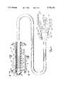
- FIG.2is a Sectional view of an intravascular ablation catheter of the present invention with a proximal end and a distal end of the catheter enlarged for clarity.
- FIG. 3is a sectional view of a shaft of the catheter of FIG. 2 taken along lines 3--3.
- FIG. 4is a sectional view of the catheter shaft of FIG. 2 taken along lines 4--4.
- FIG. 5Ais a sectional view of the catheter shaft of FIG. 2 taken along lines 5A--5A.
- FIG. 5Bis a sectional view of the catheter shaft of FIG. 2 taken along lines 5B--5B.
- FIG. 6is a plain view of a second side of the catheter shaft shown in FIGS. 5A and 5B with a balloon portion removed and as taken along lines 6--6.
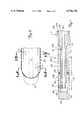
- FIG. 7is an enlarged sectional view of a microwave antenna incorporated into catheter of the present invention.
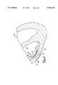
- FIG. 8is a partial sectional view of a catheter of the present invention as disposed within a ventricle of a heart for applying microwave thermal ablation therapy to the ventricle wall.
- FIG. 9is a plan view of an alternate embodiment of second side of the catheter shown in FIG. 6.
- FIG. 10is a sectional view of FIG. 9 as taken along lines 10--10.
- FIG. 11is a plain view of an second alternate embodiment of second side of the catheter shown in FIG. 6.
- FIG. 12is a sectional view of a shaft of an alternate embodiment of the catheter, similar to the view shown in FIG. 3.
- FIG. 13is a sectional view of a shaft of an alternate embodiment of the catheter, similar to the view shown in FIG. 5A.
- FIG. 1is a vertical sectional view of a human heart showing a location of damaged tissue which can cause cardiac arrhythmia.
- Heart 10includes right atrium 12, right ventricle 14, and blood 15 within atrium 12 and ventricle 14.
- Ventricle 14includes wall 16, surface 18, and damaged tissue 20.
- the damaged tissue 20 of ventricle wall 16which causes cardiac arrhythmias, such as ventricular tachycardia, can be effectively removed by heating and necrosing damaged tissue 20.
- only damaged tissue 20 of ventricle wall 16 spaced from surface 18is heated and necrosed while, at the same time, damage to ventricle wall surface 18 and to blood 15 is prevented.
- a selective thermal heating of damaged tissue 20 of ventricle wall 16is made possible by microwave antenna-containing catheter 28 of the present invention, which is shown in FIG. 2.
- FIG. 2shows a side view of catheter 28 including a sectional view of a distal end 29A of catheter 28 and a plan view of a proximal end 29B of catheter 28. Both distal end 29A and proximal end 29B are enlarged relative to shaft 32 of catheter 28 for illustrative purposes.
- catheter 28generally includes manifold 30, multi-lumen shaft 32, microwave antenna 34, cooling balloon 36, and thermometry sensor 37.
- Catheter 28is used with cooling system 38, microwave generating source 40, and thermometry unit 42.
- Manifold 30receives coaxial cable 41 (from microwave generating source 40), thermometry sensor 37, and cooling system delivery tubing 44 for alignment with corresponding lumens within shaft 32.
- Shaft 32is an extruded multi-lumen, intravascular catheter shaft connected to manifold 30 at proximal shaft end 50 via strain relief member 51.
- Manifold 30 and shaft 32are preferably made of a polymeric material such as polyethylene terephthalate (PET) sold by ATOCHEM, INC. (Glen Rock, N.J.) under the trademark PEBAXO or sold by Consolidated Polymers, Inc. under the tradename C-FLEX.
- PETpolyethylene terephthalate
- the polymeric materialpreferably has a hardness of about 20 to about 80 on the Shore D hardness scale.
- Shaft 32also includes outer surface 52.
- shaft 32includes a coating (e.g., TEFLON®) having a low coefficient of friction well known in the art forming outer surface 52 of shaft 32 to facilitate its advancement through a guide catheter positioned within the vascular system.
- Shaft 32has an outer diameter of about 0.1 inches, suitable for insertion within a 10 French size guide catheter.
- Shaft 32is long enough (e.g., 135 centimeters) and of a small enough diameter to permit insertion of distal shaft end 54 through the vascular system and into ventricle 14 (FIG. 1).
- Manifold 30preferably has a length of about 2 inches.
- a proximal portion of shaft 32can be augmented with additional design features well known to those skilled in the art to provide adequate steerability, size, pushability, tracking, and biocompatibility.
- the catheter polymer material forming shaft 32can include a radiopaque filler material well known in the art (e.g., bismuth subcarbonate or barium sulfate) to facilitate visualization of catheter shaft 32 under fluoroscopy.
- shaft 32also includes temperature sensing lumen 56, and microwave antenna lumen 58.
- Lumens 56 and 58generally extend from proximal shaft end 50 to distal shaft end 54.
- Temperature sensing lumen 56is positioned near first side 60 of shaft 32. Temperature sensing lumen 56 permits insertion of thermnometry sensor 37 within shaft 32 to monitor the temperature of adjacent tissue when shaft 32 is inserted within ventricle 14. Sensor 37- exits through manifold 30 and is connected to thermometry unit 42. In a preferred embodiment, thermometry sensor 37 is a fiber optic luminescence type temperature sensor sold by Luxtron Corporation.
- Microwave antenna lumen 58is aligned centrally relative to the longitudinal axis of shaft 32 along a majority of the length of shaft 32, antenna lumen 58 being equidistant between first side 60 of shaft 32 and second side 62 of shaft 32. However, at the distal-most end of shaft 32, adjacent cooling balloon 36, antenna lumen 58 effectively becomes oriented nearer first side 60 than second side 62 due to the presence of cooling balloon 36.. At its proximal end, antenna lumen 58 communicates with manifold 30.
- Antenna lumen 58is adapted for receiving microwave antenna 34 to be permanently positioned within antenna lumen 58 near cooling balloon 36 so that antenna 34 will be generally situated adjacent damaged tissue 20 of ventricle wall 16 when shaft 32 is properly positioned within heart 10.
- Antenna 34can be bonded within antenna lumen 58 by an adhesive bond and is carried at the distal-most end of coaxial cable 41.
- the proximal-most end of coaxial cable 41is connected to microwave generating source 40.
- Microwave generating source 40produces high frequency microwaves, preferably at about 915 MHz.
- Cooling balloon 36cooperates with multi-lumen shaft and is secured about distal end 54 of catheter shaft 32. Cooling balloon 36 is provided so that when filled with a cooling fluid, cooling balloon 36 absorbs microwave energy emitted by antenna 34 to prevent unwanted heating of blood on second side 62 of catheter 28 within a cardiac chamber of the heart while microwave energy radiating from a first side of catheter 28 heats damaged tissue 20. Cooling balloon 36 cools blood immediately surrounding and passing by the cooling balloon 36.
- Cooling balloon 36includes distal tip end 70, expandable wall portion 72, connection portion 73 and proximal waist end 74.
- Balloon 36is secured over shaft 32 by slip-fitting balloon 36 over the distal end 54 of the catheter shaft 32.
- Distal tip end 70 of balloon 36is then adhesively bonded to exterior surface 52 of shaft 32 at distal shaft end 54.
- Connection portion 73 of cooling balloon 36is adhesively bonded to outer surface 52 on shaft first side 60 while proximal waist 74 of cooling balloon 36 is adhesive bonded to outer surface 52 on both shaft sides 60 and 62.
- This arrangementcreates a sealed connection at distal end 70, proximal end 74, and along connection portion 73 to secure cooling balloon 36 on catheter shaft 32.
- An inner surface of expandable portion 72is spaced from and is not secured to shaft outer surface 52 so that expandable portion 72 remains free to expand relative to catheter outer surface 52 upon introduction and passage of an inflation cooling fluid through an interior of cooling balloon 36.
- outer surface 52 of catheter second side 62 and expandable portion 72effectively define a cooling chamber which can be inflated (as seen in FIG. 2) and deflated (shown in phantom in FIG. 2) by the selective introduction and removal of an inflation fluid within an interior of expandable wall portion 72.
- Expandable portion 72 of cooling balloon 36is positioned adjacent to microwave antenna 34 so that in use, cooling fluid within cooling balloon 36 will cool blood surrounding catheter second side 62 and absorb microwave energy radiating towards second side 62 when antenna 35 is energized.
- Cooling balloon 36extends for a length adjacent distal shaft end 54 that is substantially less than the length of catheter shaft 32, yet equal to or greater than a length of microwave antenna 34. Moreover, cooling balloon 36 has a length less than an entire length of the ventricle wall (shown in FIG. 1). For example, cooling balloon 36 preferably has a length of about 1 to 2.5 centimeters with expandable wall portion 72 preferably having a length of about 0.5 to 2 centimeters. Balloon 36 is a flexible tubular member formed of PET, cross-linked polyethylene or some other thermoplastic material that acts as a low-compliance balloon material.
- Cooling balloon 36cooperates with multi-lumen shaft 32.
- shaft 32further includes cooling lumens 76A, 76B and cooling lumens 78A, 78B in addition to temperature sensing lumen 56 and antenna lumen 58.
- Temperature sensing lumen 56preferably has a generally circular shaped transverse cross-section with a diameter of about 0.02 inches and an outer surface radius (defined by outer surface 52) of about 0.013 inches.
- Microwave antenna lumen 58preferably has a generally circular shaped transverse cross-sectional area which is substantially larger than a transverse cross-sectional area of any other respective lumen of catheter shaft 32.
- Antenna lumen 58preferably has a diameter of about 0.060 inches.
- Cooling fluid intake lumens 76A, 76Bare positioned adjacent shaft first side 60 between first side 60 and antenna lumen 58 while cooling fluid exhaust lumens 78A, 78B are positioned adjacent shaft second side 62 between second side 62 and antenna lumen 58.
- Cooling fluid intake lumens 76A, 76B and exhaust lumens 78A, 78Bextend from proximal shaft end 50 to distal shaft end 54 where lumens 76A, 76B and 78A, 78B terminate.
- Cooling fluid intake lumens 76A, 76B and exhaust lumens 78A, 78Bare defined by single wall 77 having a uniform thickness and preferably have a generally arc shaped transverse cross-section configured to surround antenna lumen 58.
- Cooling lumens 76A, 76B and 78A, 78Bpreferably have a uniform radial thickness of about 0.010 inches defined by an inner radius of about 0.035 inches and an outer radius of about 0.045 inches.
- cooling lumens 76A, 76B and cooling lumens 78A, 78Bsubstantially surround antenna lumen 58 about a substantial majority (about 75%) of a circumference of antenna lumen 58.
- Cooling lumens 76A, 76B and 78A, 78Bsurround antenna lumen 58, so that when filled with a cooling fluid, cooling exhaust lumens 78A and 78B absorb microwave energy emitted by antenna 34 (within antenna lumen 58) to protect blood immediately surrounding catheter shaft second side 62 and cooling intake lumens 76A, 76B cool tissues immediately adjacent catheter shaft first side 60.
- Cooling fluid intake lumens 76A and 76Bcommunicate with cooling exhaust lumens 78A and 78B, respectively, near distal shaft end 54 of catheter shaft 32 distal to expandable portion 72 of cooling balloon 36 (FIG. 2).
- catheter wall 77includes holes 79A and 79B and distal portion 70 of cooling balloon 36 is secured to catheter shaft outer surface 52.
- Hole 79A in catheter wall 77permits communication between cooling intake lumen 76A and cooling exhaust lumen 78A while hole 79B in catheter wall 77 permits communication between cooling intake lumen 76B and cooling exhaust lumen 78B.
- Cooling intakes lumens 76A and 76B and cooling exhaust lumens 78A and 78Bcooperate with cooling system 38 (via manifold 30) to provide a selectively controlled flow of fluid through cooling lumens 76A, 76B, 78A, and 78B during a treatment session.
- intake lumens 76A, 76B and exhaust lumens 78A, 78Bare supplied with deionized water from cooling system 38. Water from cooling system 38 is chilled to between about 12°-15° C. and pumped through cooling fluid intake lumens 76A, 76B toward distal shaft end 54. Under fluid pressure, water enters cooling fluid exhaust lumens 78A, 78B through holes 79A, 79B and returns to cooling system 38 through exhaust lumens 78A, 78B for re-chilling and re-circulation.
- FIGS. 5A and SBillustrate communication between cooling balloon 36 and cooling exhaust lumens 78A, 78B.
- FIGS. 5A and 5Bare crosssectional views of shaft 32 taken along lines 5A--5A and 5B--5B in FIG. 2.
- cooling balloon 36surrounds shaft outer surface 52 on shaft second side 62 with expandable portion 72 preferably having a generally arc shaped transverse cross-section (when inflated).
- Connection portion 73 of cooling balloon 36is secured to shaft first side 60 while expandable portion 72 is spaced from and substantially surrounds entire second side 62 including cooling fluid exhaust lumens 78A, 78B.
- Cooling balloon 36has a wall thickness of about 0.0005 to 0.005 inches, which is generally less than a wall thickness of wall 77 (e.g., 0.005 inches) defining cooling lumens 76A-78B.
- the cooling chamber defined between catheter outer surface 52 and expandable portion 72 of cooling balloon 36has a radial thickness of about 0.5 to 5.0 millimeters, which is substantially greater than a radial thickness of cooling exhaust lumens 78A, 78B (e.g., 0.25 millimeters).
- expandable portion 72 of cooling balloon 36(when inflated) defines a cooling chamber that has a transverse cross-sectional area substantially greater than the transverse cross-sectional area of cooling exhaust lumens 78A, 78B.
- an outer wall of cooling exhaust lumen 78Aincludes hole 80A and as shown in FIG. 5B, an outer wall of cooling exhaust lumen 78B includes hole 82A.
- Hole 80Apermits communication between exhaust lumen 78A and an interior of cooling balloon 36 while hole 82A permits communication between an interior of cooling balloon 36 and exhaust lumen 78B. Since fluid is flowing under pressure into cooling lumens 78A and 78B, fluid within lumen 78A enters inflatable cooling balloon 36 via hole 80A, passes through cooling balloon 36 and exits into exhaust lumen 78B via hole 82A to recirculate through cooling system 38 via manifold 30. As shown in FIG. 6, holes 80A and 80B are both axially and laterally spaced apart.
- This arrangementcreates a pressure differential between the respective holes 80A and 80B causing a passive inflation of the cooling balloon 36 and insuring that adequate fluid circulation will occur through cooling balloon 36 as cooling fluid moves through cooling lumens 76A, 76B and 78A, 78B.
- the rate of cooling fluid intake into lumens 76A, 76B and the rate of cooling fluid exhaust out of lumens 78A, 78Bcan be manipulated by cooling system 38 via manifold 30 to selectively modify the fluid pressure gradient between hole 80A and hole 80B to maintain cooling balloon 36 in an inflated state and to ensure a constant circulation of cooling fluid therethrough.
- the relative sizing of holes 80A and 80B, respectively,also can be modified to control the flow of cooling fluid in and out of the cooling balloon 36.
- hole 80Acan be made larger than hole 80B to accentuate filling of cooling balloon 36.
- microwave antenna 34The microwave radiation used to ablate target tissue 20 (FIG. 1) is emitted by microwave antenna 34.
- FIG. 7illustrates microwave antenna 34 in detail.
- Microwave antenna 34is adapted for employment in cardiovascular applications. and therefore is designed to have a low profile (minimal outer diameter) while still providing efficient powerful emission of microwave energy to selectively ablate targeted cardiac tissue 20.
- antenna 34is designed so that an outer diameter of antenna 34 is no greater than an outer diameter of coaxial cable 41, and so that antenna 34 is relatively short, e.g., about 2-3 centimeters.
- microwave antenna 34is positioned within microwave antenna lumen 58 and is surrounded by cooling lumens 76A, 76B, 78A, 78B and cooling balloon 36.
- FIG. 7illustrates a sectional view of microwave antenna 34.
- Antenna 34is positioned at the distal most end of shielded coaxial cable 41.
- Cable 41is a standard miniature 30 AWG or 32 AWG coaxial cable and can be obtained from CoonerWire of Chatsworth, Calif.
- Coaxial cable 41includes inner conductor 100, inner insulator 102, outer conductor 104, and outer insulator 106.
- Antenna 34further includes transition portion 108, reduced diameter portion 110 of inner insulator 102, first tubular extension 112, second tubular extension 114, and annular collar 116.
- Antenna 34also includes a flat wire coil 118, capacitor 120, solder 122, and end cap 124.
- First tubular extension 112encompasses outer conductor 104 and reduced diameter portion 110 of inner insulator 102. A proximal end of tubular extension 112 is positioned adjacent transition portion 108 of cable 41. Annular collar 116 also encompasses outer conductor 104 and reduced diameter portion 110 of inner insulator 102 and abuts a distal end of tubular extension 112. Annular collar 116 is a conductive material that is in electrical contact with outer conductor 104. Second tubular extension 114 also encompasses outer conductor 104 and reduced diameter portion 110 of inner insulator 102 with a proximal end of second tubular extension 114 abutting annular collar 116. A distal end of second tubular extension 114 has end cap 124 disposed therein.
- Flat wire 118forms a coil about tubular extensions 112 and 114.
- Capacitor 120is secured about a distal end of inner conductor 100 and is further electrically connected to flat wire coil 118 by solder 122 extending through hole 126.
- Reduced diameter portion 110preferably has a length of about 2 inches and an outer diameter of about 0.05 inches.
- Tubular extensions 112 and 114have lengths of 1 inches and 0.8 inches, respectively, and can have a thickness of about 0.010 inches.
- Reduced diameter portion 110 and tubular extensions 112 and 114have outer diameters (or thicknesses) of a size so that when antenna 34 is fully constructed, antenna 34 has an outer diameter of about 0.060 inches or less.
- Antenna 34includes a first coil section 140 and a second coil section 142, both of which are of equal length. These two sections are created by the electrical connection of annular collar 116 with flat wire coil 118 at a midsection of flat wire coil 118.
- first and second coil sections 140 and 142are each comprised of five equally-spaced windings of flat wire coil 118 about tubular extensions 112 and 114, respectively.
- the combined length of first and second coil sections 140 and 142provide an overall length of antenna 34 of about 2 centimeters. However, this overall length and the number of windings of the coil can be varied as needed to provide the desired length of antenna coil 118.
- flat wire 118is made of a flat ribbon of copper or silver and can be plated with a highly conductive material.
- the ribboncan be 0.02 inches wide and 0.006 inches thick.
- Flat wire 118has a physical length of 4.5 inches, which when coiled provides a total length for first coil wire section 140 and second coil wire section 142 of 2 centimeters.
- the location along coil 118 of an electrical connection between first coil section 140 and capacitor 120corresponds to a tap point used for impedance matching.
- a tap pointis selected along coil 118 so that an impedance presented between the tap point and annular collar 116 (corresponding to the point of electrical connection between coil 118 and inner conductor 100) matches the characteristic impedance of coaxial cable 41.
- the tap pointis located at the end of first coil section 140 of coil 118.
- the tap pointcan be located nearer to annular collar 116 as necessary to obtain the required impedance match.
- first coil section 140 or second coil section 142also includes an inductive component which is eliminated by providing a series capacitance such as capacitor 120. Accordingly, tubular capacitor 120 serves to counteract a reactive component of antenna 34, thereby providing a fifty (50) Ohm resistive impedance match between coaxial cable 41, microwave generating source 40, and antenna 34.
- Tubular capacitor 120preferably has a value of about 2.7 pF and can be obtained from Coors Ceramics Co. of Golden, Colo. Capacitor 120 and preferably is sized to fit over an inner conductor 100 having an inner diameter of about 0.089 to 0.012 inches has a length of 0.125 inches, an outer diameter of about 0.045 inches, and an inner diameter of about 0.025 inches.
- Tubular capacitor 120is substantially similar in design to a tubular capacitor described and shown in Rudie et al. U.S. Pat. No. 5,370,677, which is hereby incorporated by reference, and is mounted and connected to the inner conductor 100 and flat wire antenna coil 118 in a manner substantially similar to that described in Rudie et al. U.S. Pat. No. 5,370,677.
- the characteristic impedance (Zo)can be calculated with the following equation: ##EQU1## where Er is the relative dielectric constant of the inner insulator 102, D is the inner dimaeter of outer conductor 104, and d is the outer diameter of inner conductor 100.
- a characteristic impedance of 50 Ohmscan be maintained with a reduced diameter portion 110 by adjusting the ratio of D/d (e.g., reducing d), by selecting an appropriate relative dielectric constant ( ⁇ r ), or by adjusting both the ratio D/d and the relative dielectric constant ( ⁇ r ).
- any resulting impedance mismatch resulting from the altered diameter of reduced diameter portion 110 of inner insulator 102can be remedied by selecting an appropriate tap point location and a corresponding capacitor valve for capacitor 120.
- antenna 34can include platinum or gold bands located adjacent either or both ends of the flat wire antenna coil 118 to facilitate positioning of antenna 34 and catheter 28 within the cardiovascular system since the gold bands will substantially improve visualization of antenna 34 under fluoroscopy.
- Antenna 34generally has a helical dipole construction similar to the helical dipole construction of a microwave antenna described and shown in Rudie et al., U.S. Pat. Nos. 5,300,099 and 5,370,677, which are hereby incorporated by reference. Accordingly, the helical dipole construction of antenna 34 of the present invention has an effective electrical length generally equal to one-half of the wave length of the radiation emitted in the surrounding medium, e.g., the catheter shaft and surrounding tissue. Because of the helical dipole construction of antenna 34, in accordance with Rudie U.S. Pat. Nos. 5,300,099 and 5,370,677, antenna 34 can have different physical lengths yet have the same effective electrical length to produce a consistent and predictable pattern of radiation.
- microwave antenna 34 of the present inventionhas its own unique advantages. Foremost, in order to minimize the profile of the cardiovascular catheter 28 and antenna 34 located therein, the antenna 34 and coaxial cable 41 are configured and arranged so that the antenna 34 has an outer diameter that is no greater than an outer diameter of the coaxial cable 41.
- This arrangementis achieved through a combination of features. First, inner insulator 102 is modified adjacent a distal end of coaxial cable 41 into a reduced diameter portion 110 along the length of the antenna 34, and outer insulator 106 of coaxial cable 41 is replaced with outer insulating tube sections 112 and 114. Second, flat wire coil 118 is located distally beyond the end of outer insulator 106 of coaxial cable 41 so that no portion of coil 118 extends about outer insulator 106 of coaxial cable 41.
- annular collar 116is positioned to serve as the point of electrical connection between inner conductor 100 and coil 118 with outer insulator tube sections 112 and 114 being positioned on opposite sides of annular collar 116. This arrangement minimizes the length of the antenna portion of cardiovascular catheter 28 so that catheter 28 can be maneuvered more easily within the small confines of the cardiovascular system.
- FIG. 8shows an enlarged view of the ventricle 14 of FIG. 1 with catheter 28 properly positioned within ventricle 14.
- catheter 28is maneuvered into ventricle 14 through guide catheter 90.
- Guide catheter 90has a design suitable for passage through a vascular system, so that a distal end 92 of guide catheter 90 can rest supportedly adjacent ventricle wall 16 to stably support catheter 28 adjacent wall 16.
- Catheter 28is inserted into guide catheter 90 from outside the body at a remote location (e.g., femoral artery) in a manner well known in the art.
- Catheter 28is advanced through guide catheter 90 with cooling balloon 36 in its deflated state (shown in phantom in FIG. 2), which provides catheter 28 with a low profile to facilitate insertion and advancement of catheter 28 through guide catheter 90.
- Catheter shaft 28is advanced through guide catheter 90 until distal end 54 is positioned within ventricle 14 as shown in FIG. 8.
- first side 60 of shaft 32 and cooling fluid intake lumens 76A, 76Bare oriented toward ventricle wall 16 while second side 62 of shaft 32 with cooling fluid exhaust lumens 78A, 78B and cooling balloon 36 are oriented toward blood 15.
- cooling system 38is operated to provide a continuous flow of cooling fluid through cooling fluid intake lumens 76A, 76B, cooling fluid exhaust lumens 78A, 78B, and cooling balloon 36.
- Cooling balloon 36is inflated by the fluid through holes 80A and 82A from cooling exhaust lumens 78A and 78B.
- microwave energyis selectively directed into target tissue 20 by energizing microwave antenna 34 with microwave generating source 40. Since cooling fluid exhaust lumens 78A, 78B and cooling balloon 36 absorb significant amounts of microwave energy while cooling fluid intake lumens 76A, 76B, absorb very little radiation, the radiation pattern applied to the surrounding tissues becomes asymmetrical with large amounts of microwave energy acting on target tissue 20 and almost no microwave energy acting on blood 15. As a result, a relatively large volume of tissue enveloping the damaged target tissue 20, adjacent catheter first side 60, is heated according to a time and temperature relationship that effectively necroses the damaged tissue 20 of ventricle wall 16 (which causes cardiac arrhythmias).
- This preferential heating pattern created by catheter 28allows microwave energy to be concentrated only at selective locations deep within the ventricle wall 16 (e.g., up to 2 cm) at damaged tissue 20 while protecting healthy tissues (e.g., blood 15) from necrosing temperatures (e.g., above 45° C.).
- cooling system 38can be turned off thereby permitting deflation of the cooling balloon 36. Once the cooling balloon 36 is deflated, the catheter 28 can be removed from ventricle 14 proximally through the guide catheter 90.
- Intravascular catheter 28 of the present inventioncan be used as part of an intravascular microwave thermal therapy system substantially similar to the transurethral microwave thermal therapy system described and shown in Rudie et al. U.S. Pat. No. 5,413,588 and hereby incorporated by reference.
- the catheter of the present inventionpermits the application of microwave energy in a cardiovascular environment to ablate tissue lesions located deep (e.g., 2 cm) below a surface of the tissue without causing necrosis of surrounding healthy tissues.
- This capabilityis achieved by a combination of features including, amongst others, an efficient dipole helical antenna design and a microwave energy absorbing system.
- the antenna of the present inventionminimizes reflective losses, provides good current carrying capability, and has an effective electrical length that can remain consistent despite different physical lengths of the antenna.
- the microwave energy absorbing systemincludes a pair of cooling fluid intake lumens, a pair of exhaust lumens and a cooling balloon, which complements the cooling exhaust lumens.
- Cooling balloon 36 in combination with cooling exhaust lumens 78A, 78Benables cooling fluid within catheter 28 to cool blood immediately adjacent catheter second side 62 via thermal conduction.
- the cooling fluid within cooling balloon 36 and within cooling exhaust lumens 78A, 78Babsorbs a substantial amount of microwave energy (when microwave antenna 34 within antenna lumen 58 is energized) so that the temperature of blood adjacent second side 62 of shaft 32 will remain below a necrosing temperature as desired (e.g., below 45° C).
- cooling balloon 36In combination, the relatively large radial dimensions of the cooling balloon 36, and its relative position adjacent a microwave antenna on second side 62 of catheter 28 provides a cooling chamber that protects blood when a microwave antenna within lumen 58 is energized. Conversely, high levels of microwave energy are directed beyond the ventricle wall surface 18 into the ventricle wall 16 as cooling intake lumens 76A, 76B protect wall surface 18 from thermal damage without substantially absorbing microwave radiation directed toward target tissues. This enables tissue in target region 20 (FIG. 8) deep below the ventricle wall surface to be adequately necrosed while at the same time preserving blood passing by a side of the catheter opposite the target location.
- cooling balloon 36accentuates thermal conduction between cooling fluid within cooling balloon 36 and blood flowing through the ventricle since cooling balloon 36 has a wall thickness less than the cooling exhaust lumens 78A, 78B. This feature places cooling fluid into closer contact with blood within the ventricle thereby improving heat transfer away from blood within the ventricle.
- cooling balloon 36also effectively makes antenna lumen 58 nearer to shaft first side 60 than shaft second side 62 (adjacent distal shaft end 54), so that antenna lumen 58 becomes eccentric to a longitudinal axis of catheter 28 adjacent distal shaft end 54. This orientation effectively moves antenna 34 further away from blood adjacent shaft second side 62 to further reduce unwanted heating of blood 15.
- the cooling balloonis capable of being deflated as well as inflated. When deflated, the cooling balloon gives the catheter an overall low profile which facilitates insertion and advancement of the catheter through the cardiovascular system for deployment in distally remote locations, e.g., arteries and chambers of the heart.
- cooling balloon 36surrounds catheter shaft 32 with expandable portion 82 being the only portion of cooling balloon 36 spaced from catheter outer surface 53. This arrangement permits deflated cooling balloon 36 to have a low profile making cooling balloon 36 highly resistant to separation from the catheter shaft 32 and facilitating rotation of catheter 28 within urethra 10. This arrangement also simplifies the need for an elaborate system to wrap balloon 36 in deflated state.
- the cooling balloonconveniently slip fits over the distal tip of the catheter shaft thereby permitting easy manufacture of the catheter and ensuring that the balloon is properly sealed against the catheter shaft to allow proper inflation and deflation.
- interior surface of cooling balloon 36can include a coating capable of reflecting microwave energy from antenna 34, which these can further reduce the amount of microwave energy directed outwardly on the catheter second side 62.
- coating materialscan also be incorporated into shaft 32 as necessary to further prevent the emission of microwave energy in undesired locations.
- the coating materialcould be incorporated into the distal tip end of shaft 32 or along the shaft 32 proximal of antenna 34 to minimize unwanted emission of microwave energy in those areas.
- catheter 160 shown in FIG. 9has all the attributes and features of catheter 28 shown in FIGS. 2-8 except that catheter 160 includes a modified structure for communication between cooling exhaust lumens and a cooling balloon.
- catheter 160 shown in FIG. 9includes catheter shaft 161 having cooling exhaust lumens 166A and 166B, cooling balloon 168, and a first pair of holes 170A, 170B and a second pair of holes 172A, 172B.
- An outer wall of cooling exhaust lumen 166Aincludes holes 170A and 170B, which permit communication between cooling exhaust lumen 166A and an interior of cooling balloon 168.
- An outer wall of cooling exhaust lumen 166Bincludes holes 172A and 172B which permit communication between an interior of cooling balloon. 168 and cooling exhaust lumen 166B. Cooling fluid enters cooling balloon 168 through holes 170A, 172A and exits cooling balloon 168 through holes 170B, 172B.
- Catheter 160further includes restrictor 176A located between holes 170A and 170B and restrictor 176B between holes 172A and 172B, as shown in FIG. 10. For illustration purposes, only restrictor 176A located between holes 170A and 170B is shown.
- Restrictor 176Ais positioned on an outer wall of cooling exhaust lumen 166A at a location selected to create a pressure differential between holes 170A, 170B thereby causing passive inflation and active circulation of fluid through cooling balloon 168.
- Restrictor 176A as shown in FIG. 10,is preferably located immediately adjacent hole 170A and proximal to antenna 178 so that the restrictor 176B does not affect a near field radiation emitted by the antenna 178.
- the restrictor 176Acan be located at a more distal location adjacent the antenna 178 if desired.
- Restrictor 176Ais formed and added to cooling exhaust lumen 166A by depositing adhesive on an inner surface of an outer wall of cooling exhaust lumen 166A at a desired location.
- Restrictor 176Bis situated similar to restrictor 176A except being located between holes 172A and 172B in cooling exhaust lumen 166B.
- cooling fluid passing through cooling exhaust lumens 166A, 166Benters cooling balloon 168 through holes 170A and 172A thereby permitting passive inflation of cooling balloon 168.
- Restrictors 176A and 176Baccentuate passive inflation of cooling balloon 168 and circulation of fluid therethrough by creating a pressure differential between holes 170A and 170B and between holes 172A and 172B.
- Holes 170B and 172Bpermit fluid to exit cooling balloon 168 into cooling exhaust lumens 166A and 166B for recirculation through a cooling system of catheter 160 (not shown).
- FIG. 11shows another modified catheter 180 of the present invention.
- Catheter 180has all the attributes and features of catheter 28 shown in FIGS. 2-8 except that catheter 180 also includes a modified structure for communication between cooling exhaust lumens and cooling balloon 184.
- catheter 180instead of the structure shown in FIG. 6, catheter 180 includes catheter shaft 181 having cooling exhaust lumens 182A and 182B, cooling balloon 184, and a first slot 186 and a second slot 188.
- Slot 186is an elongate hole formed in the side wall of catheter shaft defining exhaust lumen 182A while slot 186 is an elongate hole formed in the side wall of catheter shaft defining exhaust lumen 182B.
- Slot 186permits unrestricted communication between cooling exhaust lumen 182A and an interior of cooling balloon 184 while slot 188 permits unrestricted communication between cooling exhaust lumen 182B and an interior of cooling balloon 184.
- This unrestricted communicationfacilitates relatively turbulent flow of cooling fluid within cooling balloon 184 thereby assuring active circulation of cooling fluid through the cooling balloon 184.
- Cooling balloon 184is passively inflated and maintained in that state by controlling the rate of fluid flow into the cooling intake lumens (not shown) and the rate of fluid flow out of the cooling exhaust lumens 182A and 182B.
- catheter 220is similar to catheter 29 of the present invention (shown in FIGS. 2-8) and has all the attributes and features of catheter 28 except that catheter 220 includes a fluid lumen for inflating a cooling balloon that is independent of cooling exhaust lumens of the catheter.
- catheter 220generally includes multi-lumen shaft 222 having outer surface 223 with first side 224 and second side 225. Shaft 222 also has a distal end and a proximal end similar to those shown for catheter 28 in FIG. 2. Distal end of shaft 222 is connected to a manifold for communication and operation with a complete thermal therapy system as previously described for catheter 28.
- multi-lumen shaft 222includes temperature sensing lumen 226, microwave antenna lumen 228, cooling balloon inflation lumen 230, cooling fluid intake lumens 232A and 232B, and cooling exhaust lumens 234A and 234B.
- Lumens 226-234Bare similar to the corresponding temperature sensing lumen 56, microwave antenna 58, cooling lumens 64A, 64B previously described for catheter 28 in association with FIG. 3.
- catheter 220further includes a cooling balloon inflation lumen 230 and includes cooling exhaust lumens 234A, 234B which have slightly different dimensions than cooling exhaust lumens 78A, 78B of catheter 28 (FIG. 3).
- Cooling balloon inflation lumen 230is positioned between cooling exhaust lumens 234A and 234B adjacent second side 225 on an opposite side of antenna lumen 228 from temperature sensing lumen 226. Cooling balloon inflation lumen 230 preferably has a generally circular cross-sectional shape with a diameter of about 0.040 inches. Cooling balloon inflation lumen 230 communicates with an inflation port in a manifold to permit inflation and deflation of cooling balloon 250.
- Cooling fluid intake lumens 232A, 232Bare positioned adjacent shaft first side 224 and have all the attributes and features of cooling intake lumens 64A, 64B (FIG. 3).
- Cooling fluid exhaust lumens 234A, 234Bare positioned adjacent shaft second side 225 and have all the attributes and features of cooling exhaust lumens 66A, 66B except having a smaller arc to accommodate cooling inflation lumens 230 positioned between lumens 234A and 234B.
- cooling exhaust lumens 234A, 234Black holes in their outer walls similar to holes 80A and 80B in cooling lumens 66A, 66B. (FIG. 6).
- cooling balloon 240surrounds shaft outer surface 223 on shaft second side 225. Cooling balloon 240 has all the attributes and features of cooling balloon 36 of catheter 28 (as previously described in association with FIGS. 2-8). As shown in FIG. 13, an outer wall of cooling balloon inflation lumen 230 includes hole 250. Hole 250 permits communication between cooling balloon inflation lumen 230 and an interior of cooling balloon 240 (shown inflated in FIG. 13). Accordingly, cooling balloon 240 is filled and inflated by the introduction of cooling fluid from cooling balloon inflation lumen 230 through hole 250.
- Cooling inflation lumen 230is independent of cooling exhaust lumens 234A, 234B enabling cooling balloon 240 to be inflated and deflated independently of fluid flow within cooling exhaust lumens 234A, 234B. This relationship provides an additional means of cooling and microwave absorption while permitting independent control of cooling fluid within cooling lumens 232A, 232B, and 234A, 234B. However, since cooling balloon 240 and cooling inflation lumen 230 do not permit recirculation of fluid within cooling balloon 240 while inflated, fluid within cooling exhaust lumens 234A, 234B are relied upon to carry heat away from cooling fluid within cooling balloon 240 via thermal conduction.
Landscapes
- Health & Medical Sciences (AREA)
- Surgery (AREA)
- Life Sciences & Earth Sciences (AREA)
- Biomedical Technology (AREA)
- Medical Informatics (AREA)
- Nuclear Medicine, Radiotherapy & Molecular Imaging (AREA)
- Electromagnetism (AREA)
- Engineering & Computer Science (AREA)
- Physics & Mathematics (AREA)
- Heart & Thoracic Surgery (AREA)
- Otolaryngology (AREA)
- Molecular Biology (AREA)
- Animal Behavior & Ethology (AREA)
- General Health & Medical Sciences (AREA)
- Public Health (AREA)
- Veterinary Medicine (AREA)
- Surgical Instruments (AREA)
Abstract
Description
Claims (22)
Priority Applications (3)
| Application Number | Priority Date | Filing Date | Title |
|---|---|---|---|
| US08/672,505US5776176A (en) | 1996-06-17 | 1996-06-17 | Microwave antenna for arterial for arterial microwave applicator |
| AU33685/97AAU3368597A (en) | 1996-06-17 | 1997-06-10 | Microwave antenna for arterial microwave applicator |
| PCT/US1997/008519WO1997048449A1 (en) | 1996-06-17 | 1997-06-10 | Microwave antenna for arterial microwave applicator |
Applications Claiming Priority (1)
| Application Number | Priority Date | Filing Date | Title |
|---|---|---|---|
| US08/672,505US5776176A (en) | 1996-06-17 | 1996-06-17 | Microwave antenna for arterial for arterial microwave applicator |
Publications (1)
| Publication Number | Publication Date |
|---|---|
| US5776176Atrue US5776176A (en) | 1998-07-07 |
Family
ID=24698836
Family Applications (1)
| Application Number | Title | Priority Date | Filing Date |
|---|---|---|---|
| US08/672,505Expired - LifetimeUS5776176A (en) | 1996-06-17 | 1996-06-17 | Microwave antenna for arterial for arterial microwave applicator |
Country Status (3)
| Country | Link |
|---|---|
| US (1) | US5776176A (en) |
| AU (1) | AU3368597A (en) |
| WO (1) | WO1997048449A1 (en) |
Cited By (101)
| Publication number | Priority date | Publication date | Assignee | Title |
|---|---|---|---|---|
| US5944749A (en)* | 1996-10-04 | 1999-08-31 | Titan Corporation | X-ray needle providing heating with microwave energy |
| US6002967A (en)* | 1997-03-26 | 1999-12-14 | International Medical Electronics, Ltd. | Diathermy apparatus with automatic tuning for applicator head |
| US6002968A (en)* | 1994-06-24 | 1999-12-14 | Vidacare, Inc. | Uterine treatment apparatus |
| WO2000035363A1 (en)* | 1998-12-14 | 2000-06-22 | Ormsby Theodore C | Radio-frequency based catheter system and hollow co-axial cable for ablation of body tissues |
| WO2000048672A1 (en) | 1999-02-19 | 2000-08-24 | Knowlton Edward W | Stomach treatment apparatus and method |
| US6246913B1 (en)* | 1997-02-14 | 2001-06-12 | Oractec Interventions, Inc. | Method and apparatus for the treatment of strabismus |
| US6368304B1 (en) | 1999-02-19 | 2002-04-09 | Alsius Corporation | Central venous catheter with heat exchange membrane |
| US6393320B2 (en) | 1999-02-19 | 2002-05-21 | Alsius Corporation | Method for treating cardiac arrest |
| US6419643B1 (en) | 1998-04-21 | 2002-07-16 | Alsius Corporation | Central venous catheter with heat exchange properties |
| US6458150B1 (en) | 1999-02-19 | 2002-10-01 | Alsius Corporation | Method and apparatus for patient temperature control |
| US6458123B1 (en)* | 2000-04-27 | 2002-10-01 | Biosense Webster, Inc. | Ablation catheter with positional sensor |
| US20030097064A1 (en)* | 2001-11-13 | 2003-05-22 | Dnyanesh Talpade | Impedance-matching apparatus and construction for intravascular device |
| US6572640B1 (en) | 2001-11-21 | 2003-06-03 | Alsius Corporation | Method and apparatus for cardiopulmonary bypass patient temperature control |
| US20030109862A1 (en)* | 2001-11-02 | 2003-06-12 | Mani Prakash | High-strength microwave antenna assemblies and methods of use |
| US6582398B1 (en) | 1999-02-19 | 2003-06-24 | Alsius Corporation | Method of managing patient temperature with a heat exchange catheter |
| US20030130711A1 (en)* | 2001-09-28 | 2003-07-10 | Pearson Robert M. | Impedance controlled tissue ablation apparatus and method |
| RU2209096C1 (en)* | 2002-01-23 | 2003-07-27 | Саратовский научно-исследовательский институт травматологии и ортопедии | Device for applying electromagnetic therapy |
| US6740082B2 (en)* | 1998-12-29 | 2004-05-25 | John H. Shadduck | Surgical instruments for treating gastro-esophageal reflux |
| US6752767B2 (en) | 2002-04-16 | 2004-06-22 | Vivant Medical, Inc. | Localization element with energized tip |
| US20040260278A1 (en)* | 1996-10-22 | 2004-12-23 | Anderson Scott C. | Apparatus and method for ablating tissue |
| US20050062666A1 (en)* | 2001-11-02 | 2005-03-24 | Vivant Medical, Inc. | High-strength microwave antenna assemblies |
| US20060142752A1 (en)* | 2001-11-29 | 2006-06-29 | Ormsby Theodore C | Radio-frequency-based catheter system with improved deflection and steering mechanisms |
| US20060147245A1 (en)* | 2004-12-30 | 2006-07-06 | Carl Cetera | Implement grip |
| US20060258937A1 (en)* | 2005-05-12 | 2006-11-16 | Daane Laurence A | Catheter with compactly terminated electronic component |
| US20060276781A1 (en)* | 2004-04-29 | 2006-12-07 | Van Der Weide Daniel W | Cannula cooling and positioning device |
| US20060289528A1 (en)* | 2003-03-26 | 2006-12-28 | Heng-Mao Chiu | Microwave antenna for medical ablation |
| US7160292B2 (en) | 1999-06-17 | 2007-01-09 | Vivant Medical, Inc. | Needle kit and method for microwave ablation, track coagulation, and biopsy |
| US20070016181A1 (en)* | 2004-04-29 | 2007-01-18 | Van Der Weide Daniel W | Microwave tissue resection tool |
| US20070049918A1 (en)* | 2005-08-24 | 2007-03-01 | Van Der Weide Daniel W | Microwave device for vascular ablation |
| US20070066972A1 (en)* | 2001-11-29 | 2007-03-22 | Medwaves, Inc. | Ablation catheter apparatus with one or more electrodes |
| US7197363B2 (en) | 2002-04-16 | 2007-03-27 | Vivant Medical, Inc. | Microwave antenna having a curved configuration |
| US7278984B2 (en) | 2002-12-31 | 2007-10-09 | Alsius Corporation | System and method for controlling rate of heat exchange with patient |
| US20070288079A1 (en)* | 2006-03-24 | 2007-12-13 | Micrablate | Energy delivery system and uses thereof |
| US20070287995A1 (en)* | 2006-06-08 | 2007-12-13 | Washington University | Cooled Ablation Catheter and Method of Using the Same |
| US20070293855A1 (en)* | 2002-02-15 | 2007-12-20 | Sliwa John W Jr | Methods and devices for ablation |
| US7311703B2 (en) | 2003-07-18 | 2007-12-25 | Vivant Medical, Inc. | Devices and methods for cooling microwave antennas |
| US20080045946A1 (en)* | 1997-10-15 | 2008-02-21 | Matthias Vaska | Devices and methods for ablating cardiac tissue |
| US20080119921A1 (en)* | 2004-04-29 | 2008-05-22 | Micrablate | Air-core microwave ablation antennas |
| US20080147056A1 (en)* | 2006-07-14 | 2008-06-19 | Micrablate | Energy delivery systems and uses thereof |
| US20080208043A1 (en)* | 2004-05-06 | 2008-08-28 | Smith Scott R | Apparatus and construction for intravascular device |
| US20080294042A1 (en)* | 2004-05-06 | 2008-11-27 | Boston Scientific Scimed, Inc. | Intravascular Antenna |
| US7467015B2 (en) | 2004-04-29 | 2008-12-16 | Neuwave Medical, Inc. | Segmented catheter for tissue ablation |
| US20090082762A1 (en)* | 2007-09-20 | 2009-03-26 | Ormsby Theodore C | Radio frequency energy transmission device for the ablation of biological tissues |
| US20090131926A1 (en)* | 2007-11-16 | 2009-05-21 | Tyco Healthcare Group Lp | Dynamically Matched Microwave Antenna for Tissue Ablation |
| US20090187180A1 (en)* | 2008-01-23 | 2009-07-23 | Vivant Medical, Inc. | Choked Dielectric Loaded Tip Dipole Microwave Antenna |
| US20090248005A1 (en)* | 2008-03-27 | 2009-10-01 | Rusin Christopher T | Microwave Ablation Devices Including Expandable Antennas and Methods of Use |
| US20090299360A1 (en)* | 2008-05-28 | 2009-12-03 | Medwaves, Inc. | Tissue ablation apparatus and method using ultrasonic imaging |
| US20090295674A1 (en)* | 2008-05-29 | 2009-12-03 | Kenlyn Bonn | Slidable Choke Microwave Antenna |
| US20100004650A1 (en)* | 2008-07-01 | 2010-01-07 | Medwaves, Inc. | Angioplasty and tissue ablation apparatus and method |
| US20100053015A1 (en)* | 2008-08-28 | 2010-03-04 | Vivant Medical, Inc. | Microwave Antenna |
| US20100087808A1 (en)* | 2008-10-03 | 2010-04-08 | Vivant Medical, Inc. | Combined Frequency Microwave Ablation System, Devices and Methods of Use |
| US20100097284A1 (en)* | 2008-10-17 | 2010-04-22 | Vivant Medical, Inc. | Choked Dielectric Loaded Tip Dipole Microwave Antenna |
| US7799019B2 (en) | 2005-05-10 | 2010-09-21 | Vivant Medical, Inc. | Reinforced high strength microwave antenna |
| US7826904B2 (en) | 2006-02-07 | 2010-11-02 | Angiodynamics, Inc. | Interstitial microwave system and method for thermal treatment of diseases |
| US20100305561A1 (en)* | 2009-06-02 | 2010-12-02 | Vivant Medical, Inc. | Electrosurgical Devices with Directional Radiation Pattern |
| US20110130750A1 (en)* | 2009-11-30 | 2011-06-02 | Medwaves, Inc. | Radio frequency ablation system with tracking sensor |
| US7998139B2 (en) | 2007-04-25 | 2011-08-16 | Vivant Medical, Inc. | Cooled helical antenna for microwave ablation |
| US20110230799A1 (en)* | 2007-04-17 | 2011-09-22 | Christian Steven C | Vacuum-Stabilized Ablation System |
| US8068921B2 (en) | 2006-09-29 | 2011-11-29 | Vivant Medical, Inc. | Microwave antenna assembly and method of using the same |
| US8128595B2 (en) | 1998-04-21 | 2012-03-06 | Zoll Circulation, Inc. | Method for a central venous line catheter having a temperature control system |
| US8292880B2 (en) | 2007-11-27 | 2012-10-23 | Vivant Medical, Inc. | Targeted cooling of deployable microwave antenna |
| US20120271334A1 (en)* | 1998-09-21 | 2012-10-25 | Benjamin Pless | Apparatus and Method for Ablating Tissue |
| US8353901B2 (en) | 2007-05-22 | 2013-01-15 | Vivant Medical, Inc. | Energy delivery conduits for use with electrosurgical devices |
| WO2013023060A1 (en)* | 2011-08-09 | 2013-02-14 | Vivant Medical, Inc. | Microwave antenna having a coaxial cable with an adjustable outer conductor configuration |
| US8535301B2 (en) | 1996-10-22 | 2013-09-17 | St. Jude Medical, Atrial Fibrillation Division, Inc. | Surgical system and procedure for treatment of medically refractory atrial fibrillation |
| US8568404B2 (en) | 2010-02-19 | 2013-10-29 | Covidien Lp | Bipolar electrode probe for ablation monitoring |
| US8651146B2 (en) | 2007-09-28 | 2014-02-18 | Covidien Lp | Cable stand-off |
| US8672932B2 (en) | 2006-03-24 | 2014-03-18 | Neuwave Medical, Inc. | Center fed dipole for use with tissue ablation systems, devices and methods |
| US8721636B2 (en) | 1996-10-22 | 2014-05-13 | St. Jude Medical, Atrial Fibrillation Division, Inc. | Apparatus and method for diagnosis and therapy of electrophysiological disease |
| US8882759B2 (en) | 2009-12-18 | 2014-11-11 | Covidien Lp | Microwave ablation system with dielectric temperature probe |
| US9023024B2 (en) | 2007-06-20 | 2015-05-05 | Covidien Lp | Reflective power monitoring for microwave applications |
| US9055959B2 (en) | 1999-07-19 | 2015-06-16 | St. Jude Medical, Atrial Fibrillation Division, Inc. | Methods and devices for ablation |
| US9113931B2 (en) | 2012-01-06 | 2015-08-25 | Covidien Lp | System and method for treating tissue using an expandable antenna |
| US9119649B2 (en) | 2009-07-28 | 2015-09-01 | Neuwave Medical, Inc. | Energy delivery systems and uses thereof |
| US9119648B2 (en) | 2012-01-06 | 2015-09-01 | Covidien Lp | System and method for treating tissue using an expandable antenna |
| US9192438B2 (en) | 2011-12-21 | 2015-11-24 | Neuwave Medical, Inc. | Energy delivery systems and uses thereof |
| US9198708B2 (en) | 2010-03-25 | 2015-12-01 | Nxthera, Inc. | Systems and methods for prostate treatment |
| US9345507B2 (en) | 2008-11-06 | 2016-05-24 | Nxthera, Inc. | Systems and methods for treatment of BPH |
| US9833277B2 (en) | 2009-04-27 | 2017-12-05 | Nxthera, Inc. | Systems and methods for prostate treatment |
| US9861440B2 (en) | 2010-05-03 | 2018-01-09 | Neuwave Medical, Inc. | Energy delivery systems and uses thereof |
| US9895185B2 (en) | 2011-09-13 | 2018-02-20 | Nxthera, Inc. | Systems and methods for prostate treatment |
| US9968395B2 (en) | 2013-12-10 | 2018-05-15 | Nxthera, Inc. | Systems and methods for treating the prostate |
| US10076384B2 (en) | 2013-03-08 | 2018-09-18 | Symple Surgical, Inc. | Balloon catheter apparatus with microwave emitter |
| US10194970B2 (en) | 2013-12-10 | 2019-02-05 | Nxthera, Inc. | Vapor ablation systems and methods |
| US10335222B2 (en) | 2012-04-03 | 2019-07-02 | Nxthera, Inc. | Induction coil vapor generator |
| US10342593B2 (en) | 2015-01-29 | 2019-07-09 | Nxthera, Inc. | Vapor ablation systems and methods |
| US10363092B2 (en) | 2006-03-24 | 2019-07-30 | Neuwave Medical, Inc. | Transmission line with heat transfer ability |
| US10531917B2 (en) | 2016-04-15 | 2020-01-14 | Neuwave Medical, Inc. | Systems and methods for energy delivery |
| US10610281B2 (en) | 2008-11-06 | 2020-04-07 | Boston Scientific Scimed, Inc. | Systems and methods for treatment of prostatic tissue |
| US10702327B2 (en) | 2015-05-13 | 2020-07-07 | Boston Scientific Scimed, Inc. | Systems and methods for treating the bladder with condensable vapor |
| US10751107B2 (en) | 2017-01-06 | 2020-08-25 | Boston Scientific Scimed, Inc. | Transperineal vapor ablation systems and methods |
| US10772670B2 (en) | 2013-03-14 | 2020-09-15 | Boston Scientific Scimed, Inc. | Systems and methods for treating prostate cancer |
| US10888496B2 (en) | 2015-09-17 | 2021-01-12 | Corvida Medical, Inc. | Medicament vial assembly |
| US10894317B2 (en) | 2015-10-13 | 2021-01-19 | Corvida Medical, Inc. | Automated compounding equipment for closed fluid transfer system |
| US10952792B2 (en) | 2015-10-26 | 2021-03-23 | Neuwave Medical, Inc. | Energy delivery systems and uses thereof |
| US10966905B2 (en) | 2008-05-14 | 2021-04-06 | Corvida Medical, Inc. | Systems and methods for safe medicament transport |
| US11246640B2 (en) | 2016-12-21 | 2022-02-15 | Boston Scientific Scimed, Inc. | Vapor ablation systems and methods |
| US11389235B2 (en) | 2006-07-14 | 2022-07-19 | Neuwave Medical, Inc. | Energy delivery systems and uses thereof |
| US11672596B2 (en) | 2018-02-26 | 2023-06-13 | Neuwave Medical, Inc. | Energy delivery devices with flexible and adjustable tips |
| US11832879B2 (en) | 2019-03-08 | 2023-12-05 | Neuwave Medical, Inc. | Systems and methods for energy delivery |
| US12440258B2 (en) | 2023-11-20 | 2025-10-14 | Boston Scientific Scimed, Inc. | Systems and methods for treating prostate cancer |
Families Citing this family (3)
| Publication number | Priority date | Publication date | Assignee | Title |
|---|---|---|---|---|
| MX348044B (en) | 2010-05-27 | 2017-05-25 | J&J Solutions Inc | Closed fluid transfer system. |
| WO2015017858A1 (en) | 2013-08-02 | 2015-02-05 | J&J SOLUTIONS, INC. d.b.a CORVIDA MEDICAL | Compounding systems and methods for safe medicament transport |
| GB2550414A (en)* | 2016-05-20 | 2017-11-22 | Creo Medical Ltd | Antenna structure |
Citations (24)
| Publication number | Priority date | Publication date | Assignee | Title |
|---|---|---|---|---|
| US4557272A (en)* | 1980-03-31 | 1985-12-10 | Microwave Associates, Inc. | Microwave endoscope detection and treatment system |
| US4559951A (en)* | 1982-11-29 | 1985-12-24 | Cardiac Pacemakers, Inc. | Catheter assembly |
| US4825880A (en)* | 1987-06-19 | 1989-05-02 | The Regents Of The University Of California | Implantable helical coil microwave antenna |
| US4832047A (en)* | 1987-12-15 | 1989-05-23 | Target Therapeutics | Guide wire device |
| US4841988A (en)* | 1987-10-15 | 1989-06-27 | Marquette Electronics, Inc. | Microwave hyperthermia probe |
| US4945318A (en)* | 1988-03-01 | 1990-07-31 | Labthermics Technologies, Inc. | Low frequency isolator for radio frequency hyperthermia probe |
| US5026959A (en)* | 1988-11-16 | 1991-06-25 | Tokyo Keiki Co. Ltd. | Microwave radiator for warming therapy |
| US5057106A (en)* | 1986-02-27 | 1991-10-15 | Kasevich Associates, Inc. | Microwave balloon angioplasty |
| EP0462302A1 (en)* | 1988-07-28 | 1991-12-27 | Bsd Medical Corporation | Urethral inserted applicator for prostate hyperthermia |
| US5246438A (en)* | 1988-11-25 | 1993-09-21 | Sensor Electronics, Inc. | Method of radiofrequency ablation |
| US5281217A (en)* | 1992-04-13 | 1994-01-25 | Ep Technologies, Inc. | Steerable antenna systems for cardiac ablation that minimize tissue damage and blood coagulation due to conductive heating patterns |
| US5300099A (en)* | 1992-03-06 | 1994-04-05 | Urologix, Inc. | Gamma matched, helical dipole microwave antenna |
| US5344435A (en)* | 1988-07-28 | 1994-09-06 | Bsd Medical Corporation | Urethral inserted applicator prostate hyperthermia |
| US5364392A (en)* | 1993-05-14 | 1994-11-15 | Fidus Medical Technology Corporation | Microwave ablation catheter system with impedance matching tuner and method |
| WO1994026188A1 (en)* | 1993-05-14 | 1994-11-24 | Fidus Medical Technology Corporation | Tunable microwave ablation catheter system and method |
| US5370676A (en)* | 1992-04-08 | 1994-12-06 | Institut National De La Sante Et De La Recherche Medicale | Device for application of hyperthermia in a particular body using microwaves |
| US5370678A (en)* | 1992-04-13 | 1994-12-06 | Ep Technologies, Inc. | Steerable microwave antenna systems for cardiac ablation that minimize tissue damage and blood coagulation due to conductive heating patterns |
| WO1995005869A1 (en)* | 1993-08-24 | 1995-03-02 | Kaare Grue | A probe for a microwave apparatus for clinical and surgical treatment |
| US5413588A (en)* | 1992-03-06 | 1995-05-09 | Urologix, Inc. | Device and method for asymmetrical thermal therapy with helical dipole microwave antenna |
| US5423811A (en)* | 1992-12-01 | 1995-06-13 | Cardiac Pathways Corporation | Method for RF ablation using cooled electrode |
| US5462521A (en)* | 1993-12-21 | 1995-10-31 | Angeion Corporation | Fluid cooled and perfused tip for a catheter |
| US5628770A (en)* | 1995-06-06 | 1997-05-13 | Urologix, Inc. | Devices for transurethral thermal therapy |
| US5643335A (en)* | 1993-07-08 | 1997-07-01 | Urologix, Inc. | Benign prostatic hyperplasia treatment catheter with urethral cooling |
| US5649973A (en)* | 1992-11-13 | 1997-07-22 | Dornier Medical Systems, Inc. | Thermotherapy method with tissue cooling |
- 1996
- 1996-06-17USUS08/672,505patent/US5776176A/ennot_activeExpired - Lifetime
- 1997
- 1997-06-10AUAU33685/97Apatent/AU3368597A/ennot_activeAbandoned
- 1997-06-10WOPCT/US1997/008519patent/WO1997048449A1/enactiveApplication Filing
Patent Citations (27)
| Publication number | Priority date | Publication date | Assignee | Title |
|---|---|---|---|---|
| US4557272A (en)* | 1980-03-31 | 1985-12-10 | Microwave Associates, Inc. | Microwave endoscope detection and treatment system |
| US4559951A (en)* | 1982-11-29 | 1985-12-24 | Cardiac Pacemakers, Inc. | Catheter assembly |
| US5057106A (en)* | 1986-02-27 | 1991-10-15 | Kasevich Associates, Inc. | Microwave balloon angioplasty |
| US4825880A (en)* | 1987-06-19 | 1989-05-02 | The Regents Of The University Of California | Implantable helical coil microwave antenna |
| US4841988A (en)* | 1987-10-15 | 1989-06-27 | Marquette Electronics, Inc. | Microwave hyperthermia probe |
| US4841988B1 (en)* | 1987-10-15 | 1990-08-14 | Marquette Electronics Inc | |
| US4832047A (en)* | 1987-12-15 | 1989-05-23 | Target Therapeutics | Guide wire device |
| US4945318A (en)* | 1988-03-01 | 1990-07-31 | Labthermics Technologies, Inc. | Low frequency isolator for radio frequency hyperthermia probe |
| EP0462302A1 (en)* | 1988-07-28 | 1991-12-27 | Bsd Medical Corporation | Urethral inserted applicator for prostate hyperthermia |
| US5344435A (en)* | 1988-07-28 | 1994-09-06 | Bsd Medical Corporation | Urethral inserted applicator prostate hyperthermia |
| US5026959A (en)* | 1988-11-16 | 1991-06-25 | Tokyo Keiki Co. Ltd. | Microwave radiator for warming therapy |
| US5246438A (en)* | 1988-11-25 | 1993-09-21 | Sensor Electronics, Inc. | Method of radiofrequency ablation |
| US5300099A (en)* | 1992-03-06 | 1994-04-05 | Urologix, Inc. | Gamma matched, helical dipole microwave antenna |
| US5413588A (en)* | 1992-03-06 | 1995-05-09 | Urologix, Inc. | Device and method for asymmetrical thermal therapy with helical dipole microwave antenna |
| US5620480A (en)* | 1992-03-06 | 1997-04-15 | Urologix, Inc. | Method for treating benign prostatic hyperplasia with thermal therapy |
| US5370676A (en)* | 1992-04-08 | 1994-12-06 | Institut National De La Sante Et De La Recherche Medicale | Device for application of hyperthermia in a particular body using microwaves |
| US5370678A (en)* | 1992-04-13 | 1994-12-06 | Ep Technologies, Inc. | Steerable microwave antenna systems for cardiac ablation that minimize tissue damage and blood coagulation due to conductive heating patterns |
| US5281217A (en)* | 1992-04-13 | 1994-01-25 | Ep Technologies, Inc. | Steerable antenna systems for cardiac ablation that minimize tissue damage and blood coagulation due to conductive heating patterns |
| US5649973A (en)* | 1992-11-13 | 1997-07-22 | Dornier Medical Systems, Inc. | Thermotherapy method with tissue cooling |
| US5423811A (en)* | 1992-12-01 | 1995-06-13 | Cardiac Pathways Corporation | Method for RF ablation using cooled electrode |
| US5405346A (en)* | 1993-05-14 | 1995-04-11 | Fidus Medical Technology Corporation | Tunable microwave ablation catheter |
| WO1994026188A1 (en)* | 1993-05-14 | 1994-11-24 | Fidus Medical Technology Corporation | Tunable microwave ablation catheter system and method |
| US5364392A (en)* | 1993-05-14 | 1994-11-15 | Fidus Medical Technology Corporation | Microwave ablation catheter system with impedance matching tuner and method |
| US5643335A (en)* | 1993-07-08 | 1997-07-01 | Urologix, Inc. | Benign prostatic hyperplasia treatment catheter with urethral cooling |
| WO1995005869A1 (en)* | 1993-08-24 | 1995-03-02 | Kaare Grue | A probe for a microwave apparatus for clinical and surgical treatment |
| US5462521A (en)* | 1993-12-21 | 1995-10-31 | Angeion Corporation | Fluid cooled and perfused tip for a catheter |
| US5628770A (en)* | 1995-06-06 | 1997-05-13 | Urologix, Inc. | Devices for transurethral thermal therapy |
Non-Patent Citations (7)
| Title |
|---|
| "Heating Characteristics of a Helical Microwave Applicator for Transurethral Hyperthermia of Benign Prostatic Hyperplasia" by M. Astrahan et al, International Journal of Hyperthermia, 1991, vol. 7, No. 1, 141-155. |
| "Implantable Helical Coil Microwave Antenna for Interstitial Hyperthermia" by Torusatoh et al, International Journal of Hyperthermia, 1988, vol. 4, No. 5.497-512. |
| "Introduction to Hyperthermia Device Evaluation" by M.D. Sapozink et al, International Journal of Hyperthermia, 1988, vol. 4, No. 1, 1-15. |
| A Dipole Antenna for Interstitial Microwave Hyperthermia by W. Hurter et al, IEEE Transactions on Microwave Theory and Techniques, vol. 39, No. 6, Jun. 1991.* |
| Heating Characteristics of a Helical Microwave Applicator for Transurethral Hyperthermia of Benign Prostatic Hyperplasia by M. Astrahan et al, International Journal of Hyperthermia, 1991, vol. 7, No. 1, 141 155.* |
| Implantable Helical Coil Microwave Antenna for Interstitial Hyperthermia by Torusatoh et al, International Journal of Hyperthermia, 1988, vol. 4, No. 5.497 512.* |
| Introduction to Hyperthermia Device Evaluation by M.D. Sapozink et al, International Journal of Hyperthermia, 1988, vol. 4, No. 1, 1 15.* |
Cited By (252)
| Publication number | Priority date | Publication date | Assignee | Title |
|---|---|---|---|---|
| US6002968A (en)* | 1994-06-24 | 1999-12-14 | Vidacare, Inc. | Uterine treatment apparatus |
| US5944749A (en)* | 1996-10-04 | 1999-08-31 | Titan Corporation | X-ray needle providing heating with microwave energy |
| US8721636B2 (en) | 1996-10-22 | 2014-05-13 | St. Jude Medical, Atrial Fibrillation Division, Inc. | Apparatus and method for diagnosis and therapy of electrophysiological disease |
| US8535301B2 (en) | 1996-10-22 | 2013-09-17 | St. Jude Medical, Atrial Fibrillation Division, Inc. | Surgical system and procedure for treatment of medically refractory atrial fibrillation |
| US20040260278A1 (en)* | 1996-10-22 | 2004-12-23 | Anderson Scott C. | Apparatus and method for ablating tissue |
| US6246913B1 (en)* | 1997-02-14 | 2001-06-12 | Oractec Interventions, Inc. | Method and apparatus for the treatment of strabismus |
| US6002967A (en)* | 1997-03-26 | 1999-12-14 | International Medical Electronics, Ltd. | Diathermy apparatus with automatic tuning for applicator head |
| US6240319B1 (en) | 1997-03-26 | 2001-05-29 | International Medical Electronics Ltd. | Diathermy apparatus with automatic tuning for applicator head |
| US20080045946A1 (en)* | 1997-10-15 | 2008-02-21 | Matthias Vaska | Devices and methods for ablating cardiac tissue |
| US8709007B2 (en) | 1997-10-15 | 2014-04-29 | St. Jude Medical, Atrial Fibrillation Division, Inc. | Devices and methods for ablating cardiac tissue |
| US6652565B1 (en) | 1998-04-21 | 2003-11-25 | Alsius Corporation | Central venous catheter with heat exchange properties |
| US6419643B1 (en) | 1998-04-21 | 2002-07-16 | Alsius Corporation | Central venous catheter with heat exchange properties |
| US8128595B2 (en) | 1998-04-21 | 2012-03-06 | Zoll Circulation, Inc. | Method for a central venous line catheter having a temperature control system |
| US20060149224A1 (en)* | 1998-05-20 | 2006-07-06 | Shadduck John H | Surgical instruments and techniques for treating gastro-esophageal reflux disease |
| US20040254622A1 (en)* | 1998-05-20 | 2004-12-16 | Shadduck John H. | Surgical instruments and techniques for treating gastro-esophageal reflux disease |
| US20100191237A1 (en)* | 1998-05-20 | 2010-07-29 | Shadduck John H | Surgical instruments and techniques for treating gastro-esophageal reflux disease |
| US20070142831A1 (en)* | 1998-05-20 | 2007-06-21 | Shadduck John H | Surgical Instruments And Techniques For Treating Gastro-Esophageal Reflux Disease |
| US8556952B2 (en) | 1998-05-20 | 2013-10-15 | Mederi Therapeutics Inc. | Surgical instruments and techniques for treating gastro-esophageal reflux disease |
| US7008419B2 (en)* | 1998-05-20 | 2006-03-07 | Shadduck John H | Surgical instruments and techniques for treating gastro-esophageal reflux disease |
| US7507239B2 (en) | 1998-05-20 | 2009-03-24 | Shadduck John H | Surgical instruments and techniques for treating gastro-esophageal reflux disease |
| US20100042091A1 (en)* | 1998-05-20 | 2010-02-18 | Mederi Therapeutics, Inc. | Surgical instruments and techniques for treating gastro-esophageal reflux disease |
| US20120271334A1 (en)* | 1998-09-21 | 2012-10-25 | Benjamin Pless | Apparatus and Method for Ablating Tissue |
| US20080015570A1 (en)* | 1998-12-14 | 2008-01-17 | Ormsby Theodore C | Hollow conductive coaxial cable for radio frequency based tissue ablation system |
| CN100558308C (en)* | 1998-12-14 | 2009-11-11 | 西奥多C.奥姆斯比 | Radio frequency based catheter system and hollow coaxial cable for ablating body tissue |
| WO2000035363A1 (en)* | 1998-12-14 | 2000-06-22 | Ormsby Theodore C | Radio-frequency based catheter system and hollow co-axial cable for ablation of body tissues |
| EP1568331B1 (en)* | 1998-12-14 | 2009-08-19 | Medwaves, Inc. | Radio-frequency based catheter system with hollow co-axial cable for ablation of body tissues |
| US8308722B2 (en) | 1998-12-14 | 2012-11-13 | Medwaves, Inc. | Hollow conductive coaxial cable for radio frequency based tissue ablation system |
| US6663625B1 (en)* | 1998-12-14 | 2003-12-16 | Theodore C. Ormsby | Radio-frequency based catheter system and hollow co-axial cable for ablation of body tissues |
| US6740082B2 (en)* | 1998-12-29 | 2004-05-25 | John H. Shadduck | Surgical instruments for treating gastro-esophageal reflux |
| WO2000048672A1 (en) | 1999-02-19 | 2000-08-24 | Knowlton Edward W | Stomach treatment apparatus and method |
| US6368304B1 (en) | 1999-02-19 | 2002-04-09 | Alsius Corporation | Central venous catheter with heat exchange membrane |
| US6516224B2 (en) | 1999-02-19 | 2003-02-04 | Alsius Corporation | Method for treating cardiac arrest |
| US6458150B1 (en) | 1999-02-19 | 2002-10-01 | Alsius Corporation | Method and apparatus for patient temperature control |
| US6582398B1 (en) | 1999-02-19 | 2003-06-24 | Alsius Corporation | Method of managing patient temperature with a heat exchange catheter |
| US6393320B2 (en) | 1999-02-19 | 2002-05-21 | Alsius Corporation | Method for treating cardiac arrest |
| US6427089B1 (en) | 1999-02-19 | 2002-07-30 | Edward W. Knowlton | Stomach treatment apparatus and method |
| US8690868B2 (en) | 1999-06-17 | 2014-04-08 | Covidien Lp | Needle kit and method for microwave ablation, track coagulation, and biopsy |
| US7160292B2 (en) | 1999-06-17 | 2007-01-09 | Vivant Medical, Inc. | Needle kit and method for microwave ablation, track coagulation, and biopsy |
| US9055959B2 (en) | 1999-07-19 | 2015-06-16 | St. Jude Medical, Atrial Fibrillation Division, Inc. | Methods and devices for ablation |
| US6458123B1 (en)* | 2000-04-27 | 2002-10-01 | Biosense Webster, Inc. | Ablation catheter with positional sensor |
| US7344533B2 (en)* | 2001-09-28 | 2008-03-18 | Angiodynamics, Inc. | Impedance controlled tissue ablation apparatus and method |
| US20030130711A1 (en)* | 2001-09-28 | 2003-07-10 | Pearson Robert M. | Impedance controlled tissue ablation apparatus and method |
| US20060293650A1 (en)* | 2001-11-02 | 2006-12-28 | Mani Prakash | High-strength microwave antenna assemblies |
| US8035570B2 (en) | 2001-11-02 | 2011-10-11 | Vivant Medical, Inc. | High-strength microwave antenna assemblies |
| US7147632B2 (en) | 2001-11-02 | 2006-12-12 | Vivant Medical Inc. | High-strength microwave antenna assemblies |
| US7862559B2 (en) | 2001-11-02 | 2011-01-04 | Vivant Medical, Inc. | High-strength microwave antenna assemblies and methods of use |
| US6878147B2 (en) | 2001-11-02 | 2005-04-12 | Vivant Medical, Inc. | High-strength microwave antenna assemblies |
| US7527623B2 (en) | 2001-11-02 | 2009-05-05 | Vivant Medical, Inc. | High-strength microwave antenna assemblies |
| US9041616B2 (en) | 2001-11-02 | 2015-05-26 | Covidien Lp | High-strength microwave antenna assemblies |
| US20030109862A1 (en)* | 2001-11-02 | 2003-06-12 | Mani Prakash | High-strength microwave antenna assemblies and methods of use |
| US20060264923A1 (en)* | 2001-11-02 | 2006-11-23 | Mani Prakash | High-strength microwave antenna assemblies |
| US7594313B2 (en) | 2001-11-02 | 2009-09-29 | Vivant Medical, Inc. | Method of manufacturing a microwave antenna assembly |
| US20050062666A1 (en)* | 2001-11-02 | 2005-03-24 | Vivant Medical, Inc. | High-strength microwave antenna assemblies |
| US20050085881A1 (en)* | 2001-11-02 | 2005-04-21 | Vivant Medical, Inc. | High-strength microwave antenna assemblies |
| US7318824B2 (en) | 2001-11-02 | 2008-01-15 | Vivant Medical, Inc. | High-strength microwave antenna assemblies |
| US9549779B2 (en) | 2001-11-02 | 2017-01-24 | Covidien Lp | High-strength microwave antenna assemblies |
| US9579152B2 (en) | 2001-11-02 | 2017-02-28 | Covidien Lp | High-strength microwave antenna assemblies |
| US7128739B2 (en) | 2001-11-02 | 2006-10-31 | Vivant Medical, Inc. | High-strength microwave antenna assemblies and methods of use |
| US8643561B2 (en) | 2001-11-02 | 2014-02-04 | Covidien Lp | High-strength microwave antenna assemblies |
| US10154880B2 (en) | 2001-11-02 | 2018-12-18 | Covidien Lp | High-strength microwave antenna assemblies |
| US20030097064A1 (en)* | 2001-11-13 | 2003-05-22 | Dnyanesh Talpade | Impedance-matching apparatus and construction for intravascular device |
| US7194297B2 (en) | 2001-11-13 | 2007-03-20 | Boston Scientific Scimed, Inc. | Impedance-matching apparatus and construction for intravascular device |
| US6572640B1 (en) | 2001-11-21 | 2003-06-03 | Alsius Corporation | Method and apparatus for cardiopulmonary bypass patient temperature control |
| US20110009858A1 (en)* | 2001-11-29 | 2011-01-13 | Medwaves, Inc. | Radio frequency-based catheter system with improved deflection and steering mechanisms |
| US8152799B2 (en) | 2001-11-29 | 2012-04-10 | Medwaves, Inc. | Radio frequency-based catheter system with improved deflection and steering mechanisms |
| US20070066972A1 (en)* | 2001-11-29 | 2007-03-22 | Medwaves, Inc. | Ablation catheter apparatus with one or more electrodes |
| US7815637B2 (en)* | 2001-11-29 | 2010-10-19 | Ormsby Theodore C | Radio-frequency-based catheter system with improved deflection and steering mechanisms |
| US20060142752A1 (en)* | 2001-11-29 | 2006-06-29 | Ormsby Theodore C | Radio-frequency-based catheter system with improved deflection and steering mechanisms |
| RU2209096C1 (en)* | 2002-01-23 | 2003-07-27 | Саратовский научно-исследовательский институт травматологии и ортопедии | Device for applying electromagnetic therapy |
| US20070293855A1 (en)* | 2002-02-15 | 2007-12-20 | Sliwa John W Jr | Methods and devices for ablation |
| US6752767B2 (en) | 2002-04-16 | 2004-06-22 | Vivant Medical, Inc. | Localization element with energized tip |
| US10143520B2 (en) | 2002-04-16 | 2018-12-04 | Covidien Lp | Microwave antenna guide assembly |
| US11045253B2 (en) | 2002-04-16 | 2021-06-29 | Covidien Lp | Electrosurgical energy channel splitters and systems for delivering electrosurgical energy |
| US10363097B2 (en) | 2002-04-16 | 2019-07-30 | Coviden Lp | Ablation system having multiple energy sources |
| US10039602B2 (en) | 2002-04-16 | 2018-08-07 | Covidien Lp | Electrosurgical energy channel splitters and systems for delivering electrosurgical energy |
| US7468042B2 (en) | 2002-04-16 | 2008-12-23 | Vivant Medical, Inc. | Localization element with energized tip |
| US7197363B2 (en) | 2002-04-16 | 2007-03-27 | Vivant Medical, Inc. | Microwave antenna having a curved configuration |
| US7846108B2 (en) | 2002-04-16 | 2010-12-07 | Vivant Medical, Inc. | Localization element with energized tip |
| US8808282B2 (en) | 2002-04-16 | 2014-08-19 | Covidien Lp | Microwave antenna having a curved configuration |
| US7278984B2 (en) | 2002-12-31 | 2007-10-09 | Alsius Corporation | System and method for controlling rate of heat exchange with patient |
| US7641632B2 (en) | 2002-12-31 | 2010-01-05 | Zoll Circulation, Inc. | System and method for controlling rate of heat exchange with patient |
| US20060289528A1 (en)* | 2003-03-26 | 2006-12-28 | Heng-Mao Chiu | Microwave antenna for medical ablation |
| US9820814B2 (en) | 2003-07-18 | 2017-11-21 | Covidien Lp | Devices and methods for cooling microwave antennas |
| US10405921B2 (en) | 2003-07-18 | 2019-09-10 | Covidien Lp | Devices and methods for cooling microwave antennas |
| US9480528B2 (en) | 2003-07-18 | 2016-11-01 | Covidien Lp | Devices and methods for cooling microwave antennas |
| US9468499B2 (en) | 2003-07-18 | 2016-10-18 | Covidien Lp | Devices and methods for cooling microwave antennas |
| US7311703B2 (en) | 2003-07-18 | 2007-12-25 | Vivant Medical, Inc. | Devices and methods for cooling microwave antennas |
| US7875024B2 (en) | 2003-07-18 | 2011-01-25 | Vivant Medical, Inc. | Devices and methods for cooling microwave antennas |
| US20080119921A1 (en)* | 2004-04-29 | 2008-05-22 | Micrablate | Air-core microwave ablation antennas |
| US20060276781A1 (en)* | 2004-04-29 | 2006-12-07 | Van Der Weide Daniel W | Cannula cooling and positioning device |
| US20070016181A1 (en)* | 2004-04-29 | 2007-01-18 | Van Der Weide Daniel W | Microwave tissue resection tool |
| US10342614B2 (en) | 2004-04-29 | 2019-07-09 | Wisconsin Alumni Research Foundation | Triaxial antenna for microwave tissue ablation |
| US20070055224A1 (en)* | 2004-04-29 | 2007-03-08 | Lee Fred T Jr | Intralumenal microwave device |
| US7467015B2 (en) | 2004-04-29 | 2008-12-16 | Neuwave Medical, Inc. | Segmented catheter for tissue ablation |
| US8116846B2 (en) | 2004-05-06 | 2012-02-14 | Boston Scientific Scimed, Inc. | Intravascular antenna |
| US20080208043A1 (en)* | 2004-05-06 | 2008-08-28 | Smith Scott R | Apparatus and construction for intravascular device |
| US20080294042A1 (en)* | 2004-05-06 | 2008-11-27 | Boston Scientific Scimed, Inc. | Intravascular Antenna |
| US7496397B2 (en) | 2004-05-06 | 2009-02-24 | Boston Scientific Scimed, Inc. | Intravascular antenna |
| US20060147245A1 (en)* | 2004-12-30 | 2006-07-06 | Carl Cetera | Implement grip |
| US8663213B2 (en) | 2005-05-10 | 2014-03-04 | Covidien Lp | Reinforced high strength microwave antenna |
| US8012148B2 (en) | 2005-05-10 | 2011-09-06 | Vivant Medical, Inc. | Reinforced high strength microwave antenna |
| US9186216B2 (en) | 2005-05-10 | 2015-11-17 | Covidien Lp | Reinforced high strength microwave antenna |
| US10537386B2 (en) | 2005-05-10 | 2020-01-21 | Covidien Lp | Reinforced high strength microwave antenna |
| US8974452B2 (en) | 2005-05-10 | 2015-03-10 | Covidien Lp | Reinforced high strength microwave antenna |
| US7799019B2 (en) | 2005-05-10 | 2010-09-21 | Vivant Medical, Inc. | Reinforced high strength microwave antenna |
| US11717347B2 (en) | 2005-05-10 | 2023-08-08 | Covidien Lp | Reinforced high strength microwave antenna |
| US8192423B2 (en) | 2005-05-10 | 2012-06-05 | Vivant Medical, Inc. | Reinforced high strength microwave antenna |
| US7660625B2 (en) | 2005-05-12 | 2010-02-09 | Tyco Electronics Corporation | Catheter with compactly terminated electronic component |
| CN101203264B (en)* | 2005-05-12 | 2010-10-20 | 泰科电子有限公司 | Catheter with compactly terminated electronic component |
| US20060258937A1 (en)* | 2005-05-12 | 2006-11-16 | Daane Laurence A | Catheter with compactly terminated electronic component |
| JP2008544774A (en)* | 2005-05-12 | 2008-12-11 | タイコ・エレクトロニクス・コーポレイション | Catheter with compactly terminated electrical components |
| WO2006124593A1 (en) | 2005-05-12 | 2006-11-23 | Tyco Electronics Corporation | Catheter with compactly terminated electronic component |
| US20070049918A1 (en)* | 2005-08-24 | 2007-03-01 | Van Der Weide Daniel W | Microwave device for vascular ablation |
| US7826904B2 (en) | 2006-02-07 | 2010-11-02 | Angiodynamics, Inc. | Interstitial microwave system and method for thermal treatment of diseases |
| US8672932B2 (en) | 2006-03-24 | 2014-03-18 | Neuwave Medical, Inc. | Center fed dipole for use with tissue ablation systems, devices and methods |
| US10363092B2 (en) | 2006-03-24 | 2019-07-30 | Neuwave Medical, Inc. | Transmission line with heat transfer ability |
| US11944376B2 (en) | 2006-03-24 | 2024-04-02 | Neuwave Medical, Inc. | Transmission line with heat transfer ability |
| US20070288079A1 (en)* | 2006-03-24 | 2007-12-13 | Micrablate | Energy delivery system and uses thereof |
| US20070287995A1 (en)* | 2006-06-08 | 2007-12-13 | Washington University | Cooled Ablation Catheter and Method of Using the Same |
| US11576723B2 (en) | 2006-07-14 | 2023-02-14 | Neuwave Medical, Inc. | Energy delivery systems and uses thereof |
| US11596474B2 (en) | 2006-07-14 | 2023-03-07 | Neuwave Medical, Inc. | Energy delivery systems and uses thereof |
| US11389235B2 (en) | 2006-07-14 | 2022-07-19 | Neuwave Medical, Inc. | Energy delivery systems and uses thereof |
| US20080147056A1 (en)* | 2006-07-14 | 2008-06-19 | Micrablate | Energy delivery systems and uses thereof |
| US11576722B2 (en) | 2006-07-14 | 2023-02-14 | Neuwave Medical, Inc. | Energy delivery systems and uses thereof |
| US10376314B2 (en) | 2006-07-14 | 2019-08-13 | Neuwave Medical, Inc. | Energy delivery systems and uses thereof |
| US9333032B2 (en) | 2006-09-29 | 2016-05-10 | Covidien Lp | Microwave antenna assembly and method of using the same |
| US8068921B2 (en) | 2006-09-29 | 2011-11-29 | Vivant Medical, Inc. | Microwave antenna assembly and method of using the same |
| US20110230799A1 (en)* | 2007-04-17 | 2011-09-22 | Christian Steven C | Vacuum-Stabilized Ablation System |
| US9314298B2 (en) | 2007-04-17 | 2016-04-19 | St. Jude Medical, Atrial Fibrillation Divisions, Inc. | Vacuum-stabilized ablation system |
| US7998139B2 (en) | 2007-04-25 | 2011-08-16 | Vivant Medical, Inc. | Cooled helical antenna for microwave ablation |
| US8628523B2 (en) | 2007-05-22 | 2014-01-14 | Covidien Lp | Energy delivery conduits for use with electrosurgical devices |
| US10271903B2 (en) | 2007-05-22 | 2019-04-30 | Covidien Lp | Energy delivery conduits for use with electrosurgical devices |
| US9301802B2 (en) | 2007-05-22 | 2016-04-05 | Covidien Lp | Energy delivery conduits for use with electrosurgical devices |
| US8353901B2 (en) | 2007-05-22 | 2013-01-15 | Vivant Medical, Inc. | Energy delivery conduits for use with electrosurgical devices |
| US9808313B2 (en) | 2007-05-22 | 2017-11-07 | Covidien Lp | Energy delivery conduits for use with electrosurgical devices |
| US9827043B2 (en) | 2007-06-20 | 2017-11-28 | Covidien Lp | Reflective power monitoring for microwave applications |
| US9023024B2 (en) | 2007-06-20 | 2015-05-05 | Covidien Lp | Reflective power monitoring for microwave applications |
| US10987165B2 (en) | 2007-06-20 | 2021-04-27 | Covidien Lp | Reflective power monitoring for microwave applications |
| US20090082762A1 (en)* | 2007-09-20 | 2009-03-26 | Ormsby Theodore C | Radio frequency energy transmission device for the ablation of biological tissues |
| US8651146B2 (en) | 2007-09-28 | 2014-02-18 | Covidien Lp | Cable stand-off |
| US9579151B2 (en) | 2007-11-16 | 2017-02-28 | Covidien Lp | Dynamically matched microwave antenna for tissue ablation |
| US8280525B2 (en) | 2007-11-16 | 2012-10-02 | Vivant Medical, Inc. | Dynamically matched microwave antenna for tissue ablation |
| US20090131926A1 (en)* | 2007-11-16 | 2009-05-21 | Tyco Healthcare Group Lp | Dynamically Matched Microwave Antenna for Tissue Ablation |
| US8968291B2 (en) | 2007-11-16 | 2015-03-03 | Covidien Lp | Dynamically matched microwave antenna for tissue ablation |
| US8292880B2 (en) | 2007-11-27 | 2012-10-23 | Vivant Medical, Inc. | Targeted cooling of deployable microwave antenna |
| US8491580B2 (en) | 2007-11-27 | 2013-07-23 | Covidien Lp | Targeted cooling of deployable microwave antenna and methods of use |
| US8655454B2 (en) | 2007-11-27 | 2014-02-18 | Covidien Lp | Targeted cooling of deployable microwave antenna with cooling chamber |
| US12318133B2 (en) | 2008-01-23 | 2025-06-03 | Covidien Lp | Choked microwave antenna |
| US20090187180A1 (en)* | 2008-01-23 | 2009-07-23 | Vivant Medical, Inc. | Choked Dielectric Loaded Tip Dipole Microwave Antenna |
| US8945111B2 (en) | 2008-01-23 | 2015-02-03 | Covidien Lp | Choked dielectric loaded tip dipole microwave antenna |
| US10058384B2 (en) | 2008-01-23 | 2018-08-28 | Covidien Lp | Choked dielectric loaded tip dipole microwave antenna |
| US10743934B2 (en) | 2008-01-23 | 2020-08-18 | Covidien Lp | Choked dielectric loaded tip dipole microwave antenna |
| US9861439B2 (en) | 2008-01-23 | 2018-01-09 | Covidien Lp | Choked dielectric loaded tip dipole microwave antenna |
| US9949794B2 (en) | 2008-03-27 | 2018-04-24 | Covidien Lp | Microwave ablation devices including expandable antennas and methods of use |
| US20090248005A1 (en)* | 2008-03-27 | 2009-10-01 | Rusin Christopher T | Microwave Ablation Devices Including Expandable Antennas and Methods of Use |
| US10966905B2 (en) | 2008-05-14 | 2021-04-06 | Corvida Medical, Inc. | Systems and methods for safe medicament transport |
| US20090299360A1 (en)* | 2008-05-28 | 2009-12-03 | Medwaves, Inc. | Tissue ablation apparatus and method using ultrasonic imaging |
| US8133222B2 (en) | 2008-05-28 | 2012-03-13 | Medwaves, Inc. | Tissue ablation apparatus and method using ultrasonic imaging |
| US20090295674A1 (en)* | 2008-05-29 | 2009-12-03 | Kenlyn Bonn | Slidable Choke Microwave Antenna |
| US8059059B2 (en) | 2008-05-29 | 2011-11-15 | Vivant Medical, Inc. | Slidable choke microwave antenna |
| US8361062B2 (en) | 2008-05-29 | 2013-01-29 | Vivant Medical, Inc. | Slidable choke microwave antenna |
| US8679106B2 (en) | 2008-07-01 | 2014-03-25 | Medwaves, Inc. | Angioplasty and tissue ablation apparatus and method |
| US20100004650A1 (en)* | 2008-07-01 | 2010-01-07 | Medwaves, Inc. | Angioplasty and tissue ablation apparatus and method |
| US20100053015A1 (en)* | 2008-08-28 | 2010-03-04 | Vivant Medical, Inc. | Microwave Antenna |
| US9113932B1 (en) | 2008-08-28 | 2015-08-25 | Covidien Lp | Microwave antenna with choke |
| US9707038B2 (en) | 2008-08-28 | 2017-07-18 | Covidien Lp | Microwave antenna with cooled handle |
| US11147620B2 (en) | 2008-08-28 | 2021-10-19 | Covidien Lp | Microwave antenna with cooled hub |
| US8251987B2 (en) | 2008-08-28 | 2012-08-28 | Vivant Medical, Inc. | Microwave antenna |
| US9375280B2 (en) | 2008-08-28 | 2016-06-28 | Covidien Lp | Microwave antenna with cooling system |
| US10022186B2 (en) | 2008-08-28 | 2018-07-17 | Covidien Lp | Microwave antenna with cooled handle |
| US9198725B2 (en) | 2008-08-28 | 2015-12-01 | Covidien Lp | Microwave antenna with choke |
| US20100087808A1 (en)* | 2008-10-03 | 2010-04-08 | Vivant Medical, Inc. | Combined Frequency Microwave Ablation System, Devices and Methods of Use |
| US20100097284A1 (en)* | 2008-10-17 | 2010-04-22 | Vivant Medical, Inc. | Choked Dielectric Loaded Tip Dipole Microwave Antenna |
| US10188460B2 (en) | 2008-10-17 | 2019-01-29 | Covidien Lp | Choked dielectric loaded tip dipole microwave antenna |
| US9113924B2 (en) | 2008-10-17 | 2015-08-25 | Covidien Lp | Choked dielectric loaded tip dipole microwave antenna |
| US12303181B2 (en) | 2008-11-06 | 2025-05-20 | Boston Scientific Scimed, Inc. | Systems and methods for treatment of prostatic tissue |
| US11564727B2 (en) | 2008-11-06 | 2023-01-31 | Boston Scientific Scimed, Inc. | Systems and methods for treatment of prostatic tissue |
| US10610281B2 (en) | 2008-11-06 | 2020-04-07 | Boston Scientific Scimed, Inc. | Systems and methods for treatment of prostatic tissue |
| US9345507B2 (en) | 2008-11-06 | 2016-05-24 | Nxthera, Inc. | Systems and methods for treatment of BPH |
| US11331135B2 (en) | 2009-04-27 | 2022-05-17 | Boston Scientific Scimed, Inc. | Systems and methods for prostate treatment |
| US9833277B2 (en) | 2009-04-27 | 2017-12-05 | Nxthera, Inc. | Systems and methods for prostate treatment |
| US10390873B2 (en) | 2009-04-27 | 2019-08-27 | Boston Scientific Scimed, Inc. | Systems and methods for prostate treatment |
| US12419678B2 (en) | 2009-04-27 | 2025-09-23 | Boston Scientific Scimed, Inc. | Systems and methods for prostate treatment |
| US8690869B2 (en) | 2009-06-02 | 2014-04-08 | Covidien Lp | Electrosurgical devices with directional radiation pattern |
| US10736694B2 (en) | 2009-06-02 | 2020-08-11 | Covidien Lp | Electrosurgical devices with directional radiation pattern |
| US20100305561A1 (en)* | 2009-06-02 | 2010-12-02 | Vivant Medical, Inc. | Electrosurgical Devices with Directional Radiation Pattern |
| US8235981B2 (en) | 2009-06-02 | 2012-08-07 | Vivant Medical, Inc. | Electrosurgical devices with directional radiation pattern |
| US9526575B2 (en) | 2009-06-02 | 2016-12-27 | Covidien Lp | Electrosurgical devices with directional radiation pattern |
| US9119649B2 (en) | 2009-07-28 | 2015-09-01 | Neuwave Medical, Inc. | Energy delivery systems and uses thereof |
| US9566115B2 (en) | 2009-07-28 | 2017-02-14 | Neuwave Medical, Inc. | Energy delivery systems and uses thereof |
| US10357312B2 (en) | 2009-07-28 | 2019-07-23 | Neuwave Medical, Inc. | Energy delivery systems and uses thereof |
| US9877783B2 (en) | 2009-07-28 | 2018-01-30 | Neuwave Medical, Inc. | Energy delivery systems and uses thereof |
| US11013557B2 (en) | 2009-07-28 | 2021-05-25 | Neuwave Medical, Inc. | Energy delivery systems and uses thereof |
| US9039698B2 (en) | 2009-11-30 | 2015-05-26 | Medwaves, Inc. | Radio frequency ablation system with tracking sensor |
| US20110130750A1 (en)* | 2009-11-30 | 2011-06-02 | Medwaves, Inc. | Radio frequency ablation system with tracking sensor |
| US8882759B2 (en) | 2009-12-18 | 2014-11-11 | Covidien Lp | Microwave ablation system with dielectric temperature probe |
| US9968401B2 (en) | 2009-12-18 | 2018-05-15 | Covidien Lp | Microwave ablation system with dielectric temperature probe |
| US8568404B2 (en) | 2010-02-19 | 2013-10-29 | Covidien Lp | Bipolar electrode probe for ablation monitoring |
| US9839477B2 (en) | 2010-02-19 | 2017-12-12 | Covidien Lp | Bipolar electrode probe for ablation monitoring |
| US9198708B2 (en) | 2010-03-25 | 2015-12-01 | Nxthera, Inc. | Systems and methods for prostate treatment |
| US11490960B2 (en) | 2010-05-03 | 2022-11-08 | Neuwave Medical, Inc. | Energy delivery systems and uses thereof |
| US10524862B2 (en) | 2010-05-03 | 2020-01-07 | Neuwave Medical, Inc. | Energy delivery systems and uses thereof |
| US9872729B2 (en) | 2010-05-03 | 2018-01-23 | Neuwave Medical, Inc. | Energy delivery systems and uses thereof |
| US10603106B2 (en) | 2010-05-03 | 2020-03-31 | Neuwave Medical, Inc. | Energy delivery systems and uses thereof |
| US9861440B2 (en) | 2010-05-03 | 2018-01-09 | Neuwave Medical, Inc. | Energy delivery systems and uses thereof |
| US12376903B2 (en) | 2010-05-03 | 2025-08-05 | Neuwave Medical, Inc. | Energy delivery systems and uses thereof |
| US10675091B2 (en) | 2011-08-09 | 2020-06-09 | Covidien Lp | Microwave antenna having a coaxial cable with an adjustable outer conductor configuration |
| US8870860B2 (en) | 2011-08-09 | 2014-10-28 | Covidien Lp | Microwave antenna having a coaxial cable with an adjustable outer conductor configuration |
| WO2013023060A1 (en)* | 2011-08-09 | 2013-02-14 | Vivant Medical, Inc. | Microwave antenna having a coaxial cable with an adjustable outer conductor configuration |
| CN103826563A (en)* | 2011-08-09 | 2014-05-28 | 柯惠有限合伙公司 | Microwave antenna having a coaxial cable with an adjustable outer conductor configuration |
| CN103826563B (en)* | 2011-08-09 | 2016-08-24 | 柯惠有限合伙公司 | Microwave antenna comprising coaxial cable with adjustable outer conductor configuration |
| US9724158B2 (en) | 2011-08-09 | 2017-08-08 | Covidien Lp | Microwave antenna having a coaxial cable with an adjustable outer conductor configuration |
| US10987150B2 (en) | 2011-09-13 | 2021-04-27 | Boston Scientific Scimed, Inc. | Systems and methods for prostate treatment |
| US9895185B2 (en) | 2011-09-13 | 2018-02-20 | Nxthera, Inc. | Systems and methods for prostate treatment |
| US11638607B2 (en) | 2011-12-21 | 2023-05-02 | Neuwave Medical, Inc. | Energy delivery systems and uses thereof |
| US9192438B2 (en) | 2011-12-21 | 2015-11-24 | Neuwave Medical, Inc. | Energy delivery systems and uses thereof |
| US10667860B2 (en) | 2011-12-21 | 2020-06-02 | Neuwave Medical, Inc. | Energy delivery systems and uses thereof |
| US9681916B2 (en) | 2012-01-06 | 2017-06-20 | Covidien Lp | System and method for treating tissue using an expandable antenna |
| US9693823B2 (en) | 2012-01-06 | 2017-07-04 | Covidien Lp | System and method for treating tissue using an expandable antenna |
| US10271902B2 (en) | 2012-01-06 | 2019-04-30 | Covidien Lp | System and method for treating tissue using an expandable antenna |
| US9113931B2 (en) | 2012-01-06 | 2015-08-25 | Covidien Lp | System and method for treating tissue using an expandable antenna |
| US9119648B2 (en) | 2012-01-06 | 2015-09-01 | Covidien Lp | System and method for treating tissue using an expandable antenna |
| US10335222B2 (en) | 2012-04-03 | 2019-07-02 | Nxthera, Inc. | Induction coil vapor generator |
| US10076384B2 (en) | 2013-03-08 | 2018-09-18 | Symple Surgical, Inc. | Balloon catheter apparatus with microwave emitter |
| US10772670B2 (en) | 2013-03-14 | 2020-09-15 | Boston Scientific Scimed, Inc. | Systems and methods for treating prostate cancer |
| US11857243B2 (en) | 2013-03-14 | 2024-01-02 | Boston Scientific Scimed, Inc. | Systems and methods for treating prostate cancer |
| US10194970B2 (en) | 2013-12-10 | 2019-02-05 | Nxthera, Inc. | Vapor ablation systems and methods |
| US9968395B2 (en) | 2013-12-10 | 2018-05-15 | Nxthera, Inc. | Systems and methods for treating the prostate |
| US12295635B2 (en) | 2013-12-10 | 2025-05-13 | Boston Scientific Scimed, Inc. | Systems and methods for treating the prostate |
| US10806502B2 (en) | 2013-12-10 | 2020-10-20 | Boston Scientific Scimed, Inc. | Systems and methods for treating the prostate |
| US11849990B2 (en) | 2013-12-10 | 2023-12-26 | Boston Scientific Scimed, Inc. | Vapor ablation systems and methods |
| US11786287B2 (en) | 2013-12-10 | 2023-10-17 | Boston Scientific Scimed, Inc. | Systems and methods for treating the prostate |
| US11559345B2 (en) | 2015-01-29 | 2023-01-24 | Boston Scientific Scimed, Inc. | Vapor ablation systems and methods |
| US10342593B2 (en) | 2015-01-29 | 2019-07-09 | Nxthera, Inc. | Vapor ablation systems and methods |
| US12232793B2 (en) | 2015-01-29 | 2025-02-25 | Boston Scientific Scimed, Inc. | Vapor ablation systems and methods |
| US11864810B2 (en) | 2015-05-13 | 2024-01-09 | Boston Scientific Scimed, Inc. | Systems and methods for treating the bladder with condensable vapor |
| US10702327B2 (en) | 2015-05-13 | 2020-07-07 | Boston Scientific Scimed, Inc. | Systems and methods for treating the bladder with condensable vapor |
| US11246641B2 (en) | 2015-05-13 | 2022-02-15 | Boston Scientific Scimed, Inc. | Systems and methods for treating the bladder with condensable vapor |
| US10888496B2 (en) | 2015-09-17 | 2021-01-12 | Corvida Medical, Inc. | Medicament vial assembly |
| US10894317B2 (en) | 2015-10-13 | 2021-01-19 | Corvida Medical, Inc. | Automated compounding equipment for closed fluid transfer system |
| US10952792B2 (en) | 2015-10-26 | 2021-03-23 | Neuwave Medical, Inc. | Energy delivery systems and uses thereof |
| US11678935B2 (en) | 2015-10-26 | 2023-06-20 | Neuwave Medical, Inc. | Energy delivery systems and uses thereof |
| US11395699B2 (en) | 2016-04-15 | 2022-07-26 | Neuwave Medical, Inc. | Systems and methods for energy delivery |
| US10531917B2 (en) | 2016-04-15 | 2020-01-14 | Neuwave Medical, Inc. | Systems and methods for energy delivery |
| US11246640B2 (en) | 2016-12-21 | 2022-02-15 | Boston Scientific Scimed, Inc. | Vapor ablation systems and methods |
| US12096967B2 (en) | 2016-12-21 | 2024-09-24 | Boston Scientific Scimed, Inc. | Vapor ablation systems and methods |
| US11992254B2 (en) | 2017-01-06 | 2024-05-28 | Boston Scientific Scimed, Inc. | Medical devices and methods |
| US10751107B2 (en) | 2017-01-06 | 2020-08-25 | Boston Scientific Scimed, Inc. | Transperineal vapor ablation systems and methods |
| US12171490B2 (en) | 2018-02-26 | 2024-12-24 | Neuwave Medical, Inc. | Energy delivery devices with flexible and adjustable tips |
| US11672596B2 (en) | 2018-02-26 | 2023-06-13 | Neuwave Medical, Inc. | Energy delivery devices with flexible and adjustable tips |
| US11832879B2 (en) | 2019-03-08 | 2023-12-05 | Neuwave Medical, Inc. | Systems and methods for energy delivery |
| US12440258B2 (en) | 2023-11-20 | 2025-10-14 | Boston Scientific Scimed, Inc. | Systems and methods for treating prostate cancer |
Also Published As
| Publication number | Publication date |
|---|---|
| AU3368597A (en) | 1998-01-07 |
| WO1997048449A1 (en) | 1997-12-24 |
Similar Documents
| Publication | Publication Date | Title |
|---|---|---|
| US5776176A (en) | Microwave antenna for arterial for arterial microwave applicator | |
| US5861021A (en) | Microwave thermal therapy of cardiac tissue | |
| US6223085B1 (en) | Device and method for preventing restenosis | |
| US12285207B2 (en) | Energy delivery systems and uses thereof | |
| AU2016256746B2 (en) | Flexible microwave catheters for natural or artificial lumens | |
| CA2321413C (en) | Radio-frequency based catheter system and hollow co-axial cable for ablation of body tissues | |
| US5464445A (en) | Device and method for asymmetrical thermal therapy with helical dipole microwave antenna | |
| CN102905639B (en) | Systems and methods for lung treatment | |
| US5330518A (en) | Method for treating interstitial tissue associated with microwave thermal therapy | |
| CN101801299B (en) | Radio frequency energy delivery device for ablation of biological tissue | |
| US20030065317A1 (en) | Microwave ablation device | |
| JP7602964B2 (en) | RF electrode ablation catheter for ventricular septum treatment with cooling function | |
| Lin | Transcatheter microwave technology for treatment of cardiovascular diseases |
Legal Events
| Date | Code | Title | Description |
|---|---|---|---|
| AS | Assignment | Owner name:UROLOGIX, INC., MINNESOTA Free format text:ASSIGNMENT OF ASSIGNORS INTEREST;ASSIGNOR:RUDIE, ERIC N.;REEL/FRAME:008118/0443 Effective date:19960821 | |
| FEPP | Fee payment procedure | Free format text:PAYOR NUMBER ASSIGNED (ORIGINAL EVENT CODE: ASPN); ENTITY STATUS OF PATENT OWNER: SMALL ENTITY | |
| STCF | Information on status: patent grant | Free format text:PATENTED CASE | |
| CC | Certificate of correction | ||
| FPAY | Fee payment | Year of fee payment:4 | |
| SULP | Surcharge for late payment | ||
| FPAY | Fee payment | Year of fee payment:8 | |
| FEPP | Fee payment procedure | Free format text:PAYER NUMBER DE-ASSIGNED (ORIGINAL EVENT CODE: RMPN); ENTITY STATUS OF PATENT OWNER: SMALL ENTITY Free format text:PAYOR NUMBER ASSIGNED (ORIGINAL EVENT CODE: ASPN); ENTITY STATUS OF PATENT OWNER: SMALL ENTITY | |
| FPAY | Fee payment | Year of fee payment:12 | |
| AS | Assignment | Owner name:MEDTRONIC, INC., MINNESOTA Free format text:SECURITY INTEREST;ASSIGNOR:UROLOGIX, INC.;REEL/FRAME:037393/0838 Effective date:20151221 | |
| AS | Assignment | Owner name:SCM SPECIALTY FINANCE OPPORTUNITIES FUND, L.P., CO Free format text:SECURITY INTEREST;ASSIGNOR:PROJECT TROJAN IP ACQUISITION LLC;REEL/FRAME:037918/0080 Effective date:20160129 | |
| AS | Assignment | Owner name:PROJECT TROJAN INTELLECTUAL PROPERTY ACQUISITION, Free format text:ASSIGNMENT BY FORECLOSURE;ASSIGNOR:UROLOGIX, INC.;REEL/FRAME:038440/0824 Effective date:20160129 | |
| AS | Assignment | Owner name:AUSLO RESEARCH LLC, CALIFORNIA Free format text:CHANGE OF NAME;ASSIGNOR:PROJECT TROJAN INTELLECTUAL PROPERTY ACQUISITION, LLC;REEL/FRAME:038612/0861 Effective date:20160129 | |
| AS | Assignment | Owner name:PROJECT TROJAN IP ACQUISITION LLC, CALIFORNIA Free format text:SECURITY INTEREST;ASSIGNOR:CNH FINANCE FUND I, L.P., F/K/A SCM SPECIALTY FINANCE OPPORTUNITIES FUND, L.P.;REEL/FRAME:048927/0800 Effective date:20190417 |