US5776154A - Surgical instruments for making precise incisions in a cardiac vessel - Google Patents
Surgical instruments for making precise incisions in a cardiac vesselDownload PDFInfo
- Publication number
- US5776154A US5776154AUS08/603,329US60332996AUS5776154AUS 5776154 AUS5776154 AUS 5776154AUS 60332996 AUS60332996 AUS 60332996AUS 5776154 AUS5776154 AUS 5776154A
- Authority
- US
- United States
- Prior art keywords
- incision
- instrument
- vessel
- blade
- point
- Prior art date
- Legal status (The legal status is an assumption and is not a legal conclusion. Google has not performed a legal analysis and makes no representation as to the accuracy of the status listed.)
- Expired - Lifetime
Links
- 230000000747cardiac effectEffects0.000title1
- 230000000149penetrating effectEffects0.000claimsabstractdescription5
- 238000000034methodMethods0.000abstractdescription32
- 210000001367arteryAnatomy0.000abstractdescription12
- 238000010009beatingMethods0.000abstractdescription12
- 239000008280bloodSubstances0.000abstractdescription8
- 210000004369bloodAnatomy0.000abstractdescription8
- 208000014674injuryDiseases0.000abstractdescription6
- 230000008733traumaEffects0.000abstractdescription6
- 210000004351coronary vesselAnatomy0.000abstractdescription4
- 230000035515penetrationEffects0.000abstractdescription2
- 210000001519tissueAnatomy0.000description13
- 238000001356surgical procedureMethods0.000description6
- 230000003872anastomosisEffects0.000description4
- 210000003813thumbAnatomy0.000description3
- 230000017531blood circulationEffects0.000description2
- 230000002612cardiopulmonary effectEffects0.000description2
- 210000000038chestAnatomy0.000description2
- 230000004087circulationEffects0.000description2
- 238000012986modificationMethods0.000description2
- 230000004048modificationEffects0.000description2
- 229910001220stainless steelInorganic materials0.000description2
- 239000010935stainless steelSubstances0.000description2
- 210000001562sternumAnatomy0.000description2
- 241001631457CannulaSpecies0.000description1
- 230000002411adverseEffects0.000description1
- QVGXLLKOCUKJST-UHFFFAOYSA-Natomic oxygenChemical compound[O]QVGXLLKOCUKJST-UHFFFAOYSA-N0.000description1
- 238000007675cardiac surgeryMethods0.000description1
- 230000000295complement effectEffects0.000description1
- 230000003247decreasing effectEffects0.000description1
- 210000003811fingerAnatomy0.000description1
- 230000003902lesionEffects0.000description1
- 239000000463materialSubstances0.000description1
- 238000003801millingMethods0.000description1
- 230000002107myocardial effectEffects0.000description1
- 229910052760oxygenInorganic materials0.000description1
- 239000001301oxygenSubstances0.000description1
- 230000002980postoperative effectEffects0.000description1
- 210000000115thoracic cavityAnatomy0.000description1
- 230000000472traumatic effectEffects0.000description1
- 230000000007visual effectEffects0.000description1
Images


Classifications
- A—HUMAN NECESSITIES
- A61—MEDICAL OR VETERINARY SCIENCE; HYGIENE
- A61B—DIAGNOSIS; SURGERY; IDENTIFICATION
- A61B17/00—Surgical instruments, devices or methods
- A61B17/32—Surgical cutting instruments
- A—HUMAN NECESSITIES
- A61—MEDICAL OR VETERINARY SCIENCE; HYGIENE
- A61B—DIAGNOSIS; SURGERY; IDENTIFICATION
- A61B17/00—Surgical instruments, devices or methods
- A61B17/32—Surgical cutting instruments
- A61B17/320016—Endoscopic cutting instruments, e.g. arthroscopes, resectoscopes
- A—HUMAN NECESSITIES
- A61—MEDICAL OR VETERINARY SCIENCE; HYGIENE
- A61B—DIAGNOSIS; SURGERY; IDENTIFICATION
- A61B17/00—Surgical instruments, devices or methods
- A61B17/00234—Surgical instruments, devices or methods for minimally invasive surgery
- A61B2017/00238—Type of minimally invasive operation
- A61B2017/00243—Type of minimally invasive operation cardiac
- A—HUMAN NECESSITIES
- A61—MEDICAL OR VETERINARY SCIENCE; HYGIENE
- A61B—DIAGNOSIS; SURGERY; IDENTIFICATION
- A61B17/00—Surgical instruments, devices or methods
- A61B2017/00681—Aspects not otherwise provided for
- A61B2017/00694—Aspects not otherwise provided for with means correcting for movement of or for synchronisation with the body
- A61B2017/00703—Aspects not otherwise provided for with means correcting for movement of or for synchronisation with the body correcting for movement of heart, e.g. ECG-triggered
- A—HUMAN NECESSITIES
- A61—MEDICAL OR VETERINARY SCIENCE; HYGIENE
- A61B—DIAGNOSIS; SURGERY; IDENTIFICATION
- A61B17/00—Surgical instruments, devices or methods
- A61B2017/00743—Type of operation; Specification of treatment sites
- A61B2017/00778—Operations on blood vessels
- A—HUMAN NECESSITIES
- A61—MEDICAL OR VETERINARY SCIENCE; HYGIENE
- A61B—DIAGNOSIS; SURGERY; IDENTIFICATION
- A61B17/00—Surgical instruments, devices or methods
- A61B17/28—Surgical forceps
- A61B17/29—Forceps for use in minimally invasive surgery
- A61B17/2909—Handles
- A61B2017/2925—Pistol grips
- A—HUMAN NECESSITIES
- A61—MEDICAL OR VETERINARY SCIENCE; HYGIENE
- A61B—DIAGNOSIS; SURGERY; IDENTIFICATION
- A61B17/00—Surgical instruments, devices or methods
- A61B17/32—Surgical cutting instruments
- A61B2017/320052—Guides for cutting instruments
Definitions
- CABGcoronary artery bypass graft
- beating heart CABG procedureuses smaller incisions, avoids the use of the extracorporeal pumps, and permits the graft procedure to be accomplished without splitting the sternum.
- beating heart CABG procedureis employed, a number of advantages are observed: patients who are treated without extracorporeal circulation recuperate faster, the hospital stay is shorter and less costly, the need for a postoperative mechanical ventilator is reduced, and the amount and frequency of blood transfusions is also reduced.
- the beating-heart CABG procedureis not widely practiced, in part, because of the difficulty in performing the necessary surgical procedures while the heart is still beating using conventional instruments. If special designed instruments were available to assist the surgeon in performing the CABG procedure on the beating heart, the procedure would be more widely practiced and the treatment of a significant patient population would be improved.
- instrumentsmust be specially designed to facilitate less invasive procedures where minimally sized incisions are placed in the chest.
- the instrumentIn many surgical procedures, such as the beating-heart CABG procedure, the instrument must be manipulated through a comparatively small opening in the chest and at a distance of at least several inches from the tissue being incised.
- instrumentsmust be specially designed to enable the surgeon to complete all the phases of the surgery by remote manipulation through small openings in the chest cavity.
- the proceduresmust be performed quickly, and without undue trauma to the tissue, and must not cause excess loss of blood.
- the surgeonIn many surgical procedures, including the beating-heart CABG procedure, the surgeon must make a substantially linear incision in a vessel, such as an artery which carries blood to the heart.
- the incisionmust completely penetrate a portion of one side of the wall of the vessel to create an opening without damaging the surrounding tissue, including in particular, the interior walls of the vessel proximate to the site of the incision.
- it is particularly important for the surgeon to create a straight, uniform incision through a portion of the vessel wallbecause a precise incision through the wall of a vessel is necessary to create the opening to which an anastomosis will be sewn and through which blood ultimately will flow.
- the surgeoncreates an incision in a vessel to receive the anastomosis, which is completed when the connection is sewn to the periphery of the opening in the artery to re-establish blood flow.
- the current techniquesare also time consuming, imprecise in creating an incision of an exact length, and may cause undue trauma to the surrounding tissue, especially when the tissue is moving due to the motion of the heart. Because blood flow through the vessel may be interrupted during the beating heart CABG procedure, it is also important that the entire incision be made rapidly. If the current techniques result in an incision which is poorly formed, this may lengthen the procedure and adversely affecting the patency of the graft when it is sewn to the periphery of the incision.
- This inventionis surgical instruments which facilitate precise and substantially linear incisions, especially through the wall of vessels, such as arteries, and which have been specially designed for coronary artery bypass graft procedures (CABG) on the beating heart.
- the instruments of this inventionare particularly useful to create the incision in the target artery to complete an anastomosis, typically the left anterior descending artery (LAD), although the actual site for any particular patient is determined clinically.
- the instruments of the inventionallow incisions to be rapidly made, precisely measured, and cleanly formed so that the bypass graft can be rapidly sewn in place.
- the instruments of the inventionalso result in less trauma to the vessel and require fewer manipulations of the vessel by the surgeon. This can be particularly significant where the interior of the vessel contains lesions or deposits.
- the inventionis a hand-held instrument with a curved cutting edge formed on the interior edge of a curved or arcuitous segment located near the end of the instrument.
- the tip of the instrumenthas a point for penetrating the vessel wall.
- the pointmay have several alternate shapes to facilitate penetration of the vessel wall while minimizing the trauma to the surrounding tissue.
- the cutting surfacemaybe disposed on one or more straight surfaces at the terminal end of the instrument.
- Another embodimentis comprised of a hand-held instrument with a movable shaft member such that the incision is created by engaging a cutting edge against a blade stop with the tissue being cut therebetween.
- This instrumentis also constructed to facilitate rapid linear incisions in a vessel while minimizing the possibility for damage to the surrounding tissue.
- the instrumentfeatures a motion-cancelling member which compensates for the movement of the target surface to be incised.
- This embodimenthas a cutting blade which is manipulated from a handle which is isolated from the movement of the tissue containing or proximate to the target of the incision.
- FIGS. 1A and 1Billustrate an embodiment of the invention used to create an incision in a vessel along line segment AB.
- FIG. 2is a detailed view of the portion of the instrument of one embodiment of the invention showing the cutting edge.
- FIG. 3illustrates a side view of one embodiment of the invention.
- FIGS. 4a -4eillustrates alternate designs for the structure of the point used with certain embodiments of the invention.
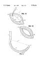
- FIG. 5is an embodiment of the invention which has a movable shaft member, a cutting edge, and a blade stop to achieve the incision.
- FIGS. 6a and 6billustrate an embodiment of the invention wherein the movable shaft member with the cutting edge engages the blade stop of FIG. 5 together with the cutting edge with which it becomes operably engaged.
- FIG. 7is an embodiment of the invention featuring a motion-cancelling device incorporated into the cutting instrument.
- the procedure whereby the surgeon makes an incision in a vessel 1 at the point at which a graft will be sewn about the periphery of the incisionmay be illustrated using an embodiment of the invention to make an incision between points A and B.
- the vesselis an artery, in particular, a coronary artery, this procedure is known as an "arteriotomy".
- the surgeondetermines an appropriate site to make the incision in the vessel 1.
- the site of the appropriate incisionis the site which the surgeon has identified as the location on the vessel at which the anastomosis will be completed.
- the incisionis generally linear and penetrates the entirety of one wall of the vessel such that the incision spans a line segment between two points A and B as shown in FIGS.
- the surgeoninserts the point 2 of the instrument 3 through point A, completely penetrating the outer wall of the vessel 1.
- the surgeonmay then orient the instrument 3, without making a further incision in the vessel 1, by inserting the portion of the instrument 3 containing the cutting edge 5 into the vessel 1 such that the point 2 of the instrument 3 is proximate to point B and such that the portion of the instrument 3 inside the vessel is comprised of the portion of the instrument 3 which features the cutting edge 5
- a curved portion 4 of the instrument 3 comprising the cutting edge 5is inside the vessel and the surgeon can visualize the location of the desired end point of the incision B on the vessel 1.
- the blunt portion of the instrumentis located on the curved portion 4 opposite the cutting edge 5 to avoid damage to the vessel 1 opposite the incision.
- the surgeonmay orient the instrument 3 such that the point 2 pushes lightly on the inside of the vessel 1 such that the location of the point 2 can be observed visually.
- the surgeonmanipulates the instrument 3 to push the point 2 through the vessel 1 from the inside such that the point 2 of the instrument 3 protrudes through point B.
- an ideal incision for receiving a graftcan be made in a few seconds with minimal chance of damage to the surrounding tissue or the interior surface of the vessel 1.
- An additional advantageis that the loss of blood from inside the vessel 1 is minimized until the time at which the surgeon is prepared to make the entire incision.
- the curved portion 4 of the instrument of one embodiment of the inventionis generally arcuitous and may comprise a portion of a circle, and is most preferably less than a semi-circle.
- the cutting edge 5is contained within the curved portion 4 of the instrument and may comprise the entire curved portion 4.
- the curved portion 4 of the instrumentterminates in a point 2 which is shaped to penetrate the vessel wall.
- the cutting edge 5is placed on a straight member (not shown) which extends from the distal (lower) end of the instrument.
- the extensioncontains the cutting edge which may also comprise a portion of the shaft of the instrument 3.
- the curved portion 4has a cutting edge 5 on the upper surface of the curved portion 4 of the instrument 3.
- the width of the curved portion 4may be approximately 0.070, but may very depending on the application, and should not be substantially thicker than the vessel to be incised.
- the embodiment shown in FIG. 2is manufactured from an oval-shaped blank, although the shape is not critical.
- the cutting surfacemay be created by any of several techniques well known to those of ordinary skill such as milling, EDM, etc.
- the material preferred for the cutting surfaceis stainless steel.
- the body of the instrument 3may be plastic having the stainless steel cutting surface attached thereto.
- the cutting edge 5is preferably created in the portion of the instrument 3 comprising the majority of the length of the curved portion 4 of the instrument.
- the opposing surface 6 of the curved portion 4 of the instrument 3is preferably smooth and rounded to avoid damaging the interior walls of the vessel 1 when inserted therein.
- the curved portion 4 and cutting edge 5form a distal (lower) portion of a hand-held embodiment of the invention having a shaft 7 and a handle 8 with a grip portion 9 to facilitate the instrument 3 being manipulated by hand.
- the point 2 of the instrumentmay have several alternative designs and shapes depending, in part, on the structural characteristics of the vessel to be incised.
- the point 2 of FIG. 4a and 4dhas three facing surfaces 10a, 10b and 10c which form the point 2 at the point of their convergence.
- a pointis formed at the convergence of two facing surfaces 11a, 11b which form a point at the convergence with the surface of the curved portion 4 of the instrument 3.
- the pointmay be formed from a cylindrical portion of the tool which has a continuously decreasing diameter to form a pin-like point 2, which may be offset of center (FIG. 4e).
- a cutting edge 14is mounted on a blade member 13 attached to a movable shaft member 15 which comprises a rigid shaft 20 and moves vertically along the length of the instrument 13 and operably engages a blade stop 16 which defines the range of motion of the movable shaft member 15 and terminates the downward movement thereof.
- the cutting edge 14 and the blade stop 16are operably engaged when each contacts the other to cut tissue positioned therebetween.
- the blade stop 16is manipulated in a manner similar to the embodiment described above and in FIG. 2 and as shown in FIG. 1. However, in this instance, the blade stop 16 is inserted into the vessel and oriented such that the cutting edge 14 and the blade stop 16 are brought together to create an incision at the desired location in the artery wall.
- the downward motion of movable shaft member 15 of the instrumentis controlled by a thumb control 17 attached to the a shaft 20.
- the movable shaft member 15 and cutting edge 14are actuated from a thumb control at the proximal (upper) end of the instrument proximate to the grip of the instrument.
- the rigid shaft 20passes into and is contained within the housing 18 of the instrument.
- the movable shaft member 15is tensioned with a pressure spring 21 such that the moveable shaft member 15 remains retracted and the cutting edge 14 and the blade stop 16 are restrained from engaging in another until the blade stop 16 is positioned in the vessel and until the incision is desired to be made.
- the housing 18 of the instrument of this embodiment of the inventionmay have several structural and design alternatives and modifications without altering the essential function of the device.
- the housing 18 of the instrumentprovides a hand-held structural portion which is fixed relative to the movable shaft member 15 such that the movable shaft member 15 can move vertically to engage the cutting edge 14 and blade stop 16 to readily accomplish the incision.
- the housing 18 of the instrumentmay be hollow, containing the movable shaft member 15, the rigid shaft 20 and guide means, such as a rail, which enables reproducible linear movement of the movable shaft member 15.
- the blade stop 16is designed to penetrate the vessel with a point 11 substantially as described in connection with the embodiment of FIGS. 1-3.
- the pointmay have any of the shapes or configurations depicted in FIGS. 4A-4E incorporated into the blade stop 16.
- the structure of the blade stop 16 proximate to the point 11is shaped to function as the blade stop 16 for the cutting edge 14 by having a complementary shape such that when the cutting edge 14 operably engages the blade stop 16, the tissue or other structure therebetween is cut.
- the blade stop 16has an upper surface 17 at the terminal end of the instrument having a groove 17a or like structure disposed in the upper surface 17 such that the cutting edge 14 fits conformingly therein.
- the overall length of the blade stop 16also may be varied to accommodate the desired length of the incision or may match the length and configuration of the cutting edge 14. Depending on the application, the cutting edge 14 and blade stop 16 may have sufficient length to perform the desired incision in one cycle of the instrument. Alternatively, several cycles of the instrument may be performed. As in the first embodiment described above, the bottom surface of the portion of the tool inserted into the artery the is smooth to avoid damage to the interior portion of the vessel opposite the site of the incision.
- the housing 18may also be a substantially closed cylindrical structure with the movable shaft member is contained entirely within.
- the direction of movement of the movable shaft member 15is preferably controlled by a series of guides which surround the movable member 15 in an annular fashion to provide controlled linear movement when the cutting edge 14 engages the blade stop 16 to achieve the desired incision.
- the instrumentmay also have a gripping means such as finger rings 12 or other such structures to facilitate being held by hand.
- the movable shaft member 15may be spring-loaded such as by a spring 21 coiled between the thumb control 17 and the housing 18 of the instrument or may be otherwise tensioned by conventional means in either direction such that the cutting edge 14 and blade stop 16 are drawn together or apart.
- a further alternative embodiment of the inventionwhich is useful for making an incision in any moving structure, is comprising of a fixed handle 21 with blunt stylus point 22 that rests on the surface of a moving vessel 23 and moves freely in conjunction therewith.
- the instrumenthas a blade member 24 with a cutting edge 27 and freely moves relative to the moving vessel 23, and moves in conjunction with the blunt stylus point 22, but which may be controlled from a fixed handle 21.
- the motion of the blunt stylus point 22helps to compensate for the movement of the moving vessel 23 relative to the visual field of the surgeon.
- the fixed handle 21is grasped by the surgeon, at the distal end thereof.
- the blunt stylus point 22is affixed to the fixed handle 21 by a pivot joint 25 which may be lightly damped or spring tensioned such that the blunt stylus point 22 rests against the moving vessel 23 and maintains continuous contact therewith.
- the blade member 24is preferably attached to the fixed handle 21, intermediate to the pivot joint 25 and a control lever 26 which is attached to the fixed handle 21 and to the blade member 24 so that the blade can be moved independent of the blunt stylus point 22 to contact the moving vessel 23 structure where the incision is to be made.
- the blade member 24is attached to the blunt stylus point 22 with a rigid interconnecting shaft 27 so that the blade member 24 moves in tandem with the blunt stylus point 22 relative to any structure in contact with the blunt stylus point 22.
- the control lever 26is slidably connected to the blade member 24 by providing a pin 30 at the end of the control lever 26 at the point of attachment to the blade member 24 and which is disposed to slide within a slot 29 in the blade member 24 thereby permitting the cutting edge 28 to operate below the level of the blunt stylus 22 to create the incision in the moving vessel 23.
Landscapes
- Health & Medical Sciences (AREA)
- Life Sciences & Earth Sciences (AREA)
- Surgery (AREA)
- Heart & Thoracic Surgery (AREA)
- Engineering & Computer Science (AREA)
- Biomedical Technology (AREA)
- Nuclear Medicine, Radiotherapy & Molecular Imaging (AREA)
- Medical Informatics (AREA)
- Molecular Biology (AREA)
- Animal Behavior & Ethology (AREA)
- General Health & Medical Sciences (AREA)
- Public Health (AREA)
- Veterinary Medicine (AREA)
- Surgical Instruments (AREA)
Abstract
Description
Claims (2)
Priority Applications (3)
| Application Number | Priority Date | Filing Date | Title |
|---|---|---|---|
| US08/603,329US5776154A (en) | 1996-02-20 | 1996-02-20 | Surgical instruments for making precise incisions in a cardiac vessel |
| US09/027,611US6113616A (en) | 1996-02-20 | 1998-02-23 | Surgical instruments for making precise incisions in a cardiac vessel |
| US09/541,851US6387108B1 (en) | 1996-02-20 | 2000-04-03 | Surgical instruments for making precise incisions in a cardiac vessel |
Applications Claiming Priority (1)
| Application Number | Priority Date | Filing Date | Title |
|---|---|---|---|
| US08/603,329US5776154A (en) | 1996-02-20 | 1996-02-20 | Surgical instruments for making precise incisions in a cardiac vessel |
Related Child Applications (1)
| Application Number | Title | Priority Date | Filing Date |
|---|---|---|---|
| US09/027,611DivisionUS6113616A (en) | 1996-02-20 | 1998-02-23 | Surgical instruments for making precise incisions in a cardiac vessel |
Publications (1)
| Publication Number | Publication Date |
|---|---|
| US5776154Atrue US5776154A (en) | 1998-07-07 |
Family
ID=24414966
Family Applications (3)
| Application Number | Title | Priority Date | Filing Date |
|---|---|---|---|
| US08/603,329Expired - LifetimeUS5776154A (en) | 1996-02-20 | 1996-02-20 | Surgical instruments for making precise incisions in a cardiac vessel |
| US09/027,611Expired - Fee RelatedUS6113616A (en) | 1996-02-20 | 1998-02-23 | Surgical instruments for making precise incisions in a cardiac vessel |
| US09/541,851Expired - LifetimeUS6387108B1 (en) | 1996-02-20 | 2000-04-03 | Surgical instruments for making precise incisions in a cardiac vessel |
Family Applications After (2)
| Application Number | Title | Priority Date | Filing Date |
|---|---|---|---|
| US09/027,611Expired - Fee RelatedUS6113616A (en) | 1996-02-20 | 1998-02-23 | Surgical instruments for making precise incisions in a cardiac vessel |
| US09/541,851Expired - LifetimeUS6387108B1 (en) | 1996-02-20 | 2000-04-03 | Surgical instruments for making precise incisions in a cardiac vessel |
Country Status (1)
| Country | Link |
|---|---|
| US (3) | US5776154A (en) |
Cited By (27)
| Publication number | Priority date | Publication date | Assignee | Title |
|---|---|---|---|---|
| US6033362A (en)* | 1997-04-25 | 2000-03-07 | Beth Israel Deaconess Medical Center | Surgical retractor and method of use |
| US6458079B1 (en)* | 1997-04-25 | 2002-10-01 | Beth Israel Deaconess Medical Center | Surgical retractor and method of use |
| US6558314B1 (en) | 2000-02-11 | 2003-05-06 | Iotek, Inc. | Devices and method for manipulation of organ tissue |
| EP1330986A1 (en)* | 2002-01-25 | 2003-07-30 | Terumo Kabushiki Kaisha | Vascular incision apparatus |
| US20030176765A1 (en)* | 2002-01-23 | 2003-09-18 | Foley Frederick J. | Devices for holding a body organ |
| US6629980B1 (en)* | 2000-11-28 | 2003-10-07 | The Regents Of The University Of Michigan | Instrument and method for creating an intraocular incision |
| US6641604B1 (en) | 2000-02-11 | 2003-11-04 | Iotek, Inc. | Devices and method for manipulation of organ tissue |
| US6663622B1 (en) | 2000-02-11 | 2003-12-16 | Iotek, Inc. | Surgical devices and methods for use in tissue ablation procedures |
| US6695833B1 (en) | 2000-09-27 | 2004-02-24 | Nellix, Inc. | Vascular stent-graft apparatus and forming method |
| US20040086915A1 (en)* | 2002-08-28 | 2004-05-06 | Board Of Regents, The University Of Texas System | Quantitative RT-PCR to AC133 to diagnose cancer and monitor angiogenic activity in a cell sample |
| US20040102797A1 (en)* | 1999-04-05 | 2004-05-27 | Coalescent Surgical, Inc. | Apparatus and methods for anastomosis |
| US20040116950A1 (en)* | 2000-11-28 | 2004-06-17 | The Regents Of The University Of Michigan | Instrument and method for creating an intraocular incision |
| US20040138685A1 (en)* | 2003-01-14 | 2004-07-15 | Clague Cynthia T. | Methods and apparatus for making precise incisions in body vessels |
| US20050033338A1 (en)* | 2003-06-19 | 2005-02-10 | Ferree Bret A. | Surgical instruments particularly suited to severing ligaments and fibrous tissues |
| US20050033277A1 (en)* | 2002-10-23 | 2005-02-10 | Clague Cynthia T. | Electrosurgical methods and apparatus for making precise incisions in body vessels |
| US20050065542A1 (en)* | 2003-07-08 | 2005-03-24 | Board Of Regents, The University Of Texas System | Surgical cutting tools and related methods |
| US20050165427A1 (en)* | 2004-01-22 | 2005-07-28 | Jahns Scott E. | Vessel sealing devices |
| US20060095055A1 (en)* | 2004-10-29 | 2006-05-04 | Peter Douglas | Device for incising a blood vessel |
| US7235049B1 (en)* | 1997-04-25 | 2007-06-26 | Beth Israel Deaconess Medical Center | Surgical retractor and method of positioning an artery during surgery |
| WO2007120063A3 (en)* | 2006-04-19 | 2008-01-31 | Andrzej Kukwa | Multifunctional surgical instrument for precise operations, particularly for laryngologic and neurosurgical operations |
| WO2009036317A3 (en)* | 2007-09-12 | 2009-04-30 | Daniel H Drake | Mitral hook |
| US7763077B2 (en) | 2003-12-24 | 2010-07-27 | Biomerix Corporation | Repair of spinal annular defects and annulo-nucleoplasty regeneration |
| US7803395B2 (en) | 2003-05-15 | 2010-09-28 | Biomerix Corporation | Reticulated elastomeric matrices, their manufacture and use in implantable devices |
| US8956376B2 (en) | 2011-06-30 | 2015-02-17 | The Spectranetics Corporation | Reentry catheter and method thereof |
| US8998936B2 (en) | 2011-06-30 | 2015-04-07 | The Spectranetics Corporation | Reentry catheter and method thereof |
| US9532799B2 (en) | 1999-08-19 | 2017-01-03 | Covidien Lp | Method and devices for cutting tissue |
| US9814862B2 (en) | 2011-06-30 | 2017-11-14 | The Spectranetics Corporation | Reentry catheter and method thereof |
Families Citing this family (21)
| Publication number | Priority date | Publication date | Assignee | Title |
|---|---|---|---|---|
| US6979338B1 (en) | 1998-05-29 | 2005-12-27 | By-Pass Inc. | Low profile anastomosis connector |
| US20040049221A1 (en)* | 1998-05-29 | 2004-03-11 | By-Pass, Inc. | Method and apparatus for forming apertures in blood vessels |
| KR20010052459A (en) | 1998-05-29 | 2001-06-25 | 바이-패스, 인크. | Methods and devices for vascular surgery |
| US7063711B1 (en) | 1998-05-29 | 2006-06-20 | By-Pass, Inc. | Vascular surgery |
| EP1085837A4 (en)* | 1998-05-29 | 2004-06-02 | By Pass Inc | Vascular port device |
| JP2004500209A (en)* | 2000-03-20 | 2004-01-08 | バイ−パス・インク. | Transfer of grafts and connectors |
| US6527771B1 (en)* | 2001-09-28 | 2003-03-04 | Ethicon, Inc. | Surgical device for endoscopic vein harvesting |
| US7530987B1 (en) | 2002-04-24 | 2009-05-12 | Cardica, Inc. | Surgical tool for creating an incision in a tubular vessel |
| US20060116707A1 (en)* | 2002-09-25 | 2006-06-01 | By-Pass, Inc | Blood vessel cutter |
| WO2004028376A1 (en)* | 2002-09-25 | 2004-04-08 | By-Pass, Inc. | Sliding surgical clip |
| US20060025788A1 (en)* | 2002-09-25 | 2006-02-02 | By-Pass, Inc. | Anastomotic leg arrangement |
| US7361181B2 (en)* | 2002-10-04 | 2008-04-22 | St. Jude Medical Atg, Inc. | Apparatus and methods for creating anastomoses |
| JP3980989B2 (en)* | 2002-10-31 | 2007-09-26 | マニー株式会社 | Blood vessel knife |
| US20060095056A1 (en)* | 2004-10-29 | 2006-05-04 | Peter Douglas | Device for incising a blood vessel |
| CH697179A5 (en)* | 2004-12-17 | 2008-06-25 | Zuercher Hochschule Winterthur | Surgical cutting instrument. |
| US8685050B2 (en) | 2010-10-06 | 2014-04-01 | Rex Medical L.P. | Cutting wire assembly for use with a catheter |
| US8685049B2 (en) | 2010-11-18 | 2014-04-01 | Rex Medical L.P. | Cutting wire assembly for use with a catheter |
| US9282991B2 (en) | 2010-10-06 | 2016-03-15 | Rex Medical, L.P. | Cutting wire assembly with coating for use with a catheter |
| US8702736B2 (en) | 2010-11-22 | 2014-04-22 | Rex Medical L.P. | Cutting wire assembly for use with a catheter |
| WO2014055981A1 (en) | 2012-10-05 | 2014-04-10 | Board Of Regents, The University Of Texas System | System and method for scoring the left ventricular endocardium to increase left ventricular compliance |
| US10433861B2 (en) | 2013-08-27 | 2019-10-08 | Board Of Regents Of The University Of Texas System | System and method for cutting trabeculae carneae of the left ventricle to increase LV compliance |
Citations (4)
| Publication number | Priority date | Publication date | Assignee | Title |
|---|---|---|---|---|
| US5304190A (en)* | 1992-05-08 | 1994-04-19 | Ethicon, Inc. | Endoscopic cutting apparatus |
| US5314440A (en)* | 1992-11-02 | 1994-05-24 | Henry Shapiro | Microsurgical scissor apparatus |
| US5397333A (en)* | 1993-09-24 | 1995-03-14 | Nusurg Medical, Inc. | Surgical hook knife |
| US5562693A (en)* | 1995-08-11 | 1996-10-08 | Alcon Laboratories, Inc. | Cutting blade assembly for a surgical scissors |
Family Cites Families (6)
| Publication number | Priority date | Publication date | Assignee | Title |
|---|---|---|---|---|
| US2249906A (en)* | 1938-09-03 | 1941-07-22 | Ramon Castroviejo | Surgical device |
| US3752161A (en)* | 1971-08-02 | 1973-08-14 | Minnesota Mining & Mfg | Fluid operated surgical tool |
| US5047042A (en)* | 1990-02-09 | 1991-09-10 | Ravinder Jerath | Cervical conization method and instrument |
| US5683359A (en)* | 1992-11-18 | 1997-11-04 | Symbiosis Corporation | Arthroscopic surgical instruments having suction capability |
| US5545172A (en)* | 1994-06-07 | 1996-08-13 | Malvern Technologies, Inc. | Rocking foot plate for surgical knife |
| US6007554A (en)* | 1998-09-03 | 1999-12-28 | Van Ess; Lester Jay | Surgical cutter |
- 1996
- 1996-02-20USUS08/603,329patent/US5776154A/ennot_activeExpired - Lifetime
- 1998
- 1998-02-23USUS09/027,611patent/US6113616A/ennot_activeExpired - Fee Related
- 2000
- 2000-04-03USUS09/541,851patent/US6387108B1/ennot_activeExpired - Lifetime
Patent Citations (4)
| Publication number | Priority date | Publication date | Assignee | Title |
|---|---|---|---|---|
| US5304190A (en)* | 1992-05-08 | 1994-04-19 | Ethicon, Inc. | Endoscopic cutting apparatus |
| US5314440A (en)* | 1992-11-02 | 1994-05-24 | Henry Shapiro | Microsurgical scissor apparatus |
| US5397333A (en)* | 1993-09-24 | 1995-03-14 | Nusurg Medical, Inc. | Surgical hook knife |
| US5562693A (en)* | 1995-08-11 | 1996-10-08 | Alcon Laboratories, Inc. | Cutting blade assembly for a surgical scissors |
Non-Patent Citations (4)
| Title |
|---|
| "Direct Myocardial Revascularization by Saphenous Vein Graft," R.G. Favaloro, M.D.; D.B. Effler, M.D.; L.K. Groves, M.D.; W.G. Sheldon, M.D.; and F.M. Sones, Jr., M.D. The Annals of Thoracic Surgery, vol. 10, No. 2, Aug., 1970. |
| Direct Myocardial Revascularization by Saphenous Vein Graft, R.G. Favaloro, M.D.; D.B. Effler, M.D.; L.K. Groves, M.D.; W.G. Sheldon, M.D.; and F.M. Sones, Jr., M.D. The Annals of Thoracic Surgery , vol. 10, No. 2, Aug., 1970.* |
| Geister product insert for Article No. 16 1020, Diamond Knife for Coronary Surgery.* |
| Geister product insert for Article No. 16-1020, Diamond Knife for Coronary Surgery. |
Cited By (54)
| Publication number | Priority date | Publication date | Assignee | Title |
|---|---|---|---|---|
| US7736308B2 (en) | 1997-04-25 | 2010-06-15 | Teleflex-Ct Devices Incorporated | Surgical retractor |
| US7468030B1 (en) | 1997-04-25 | 2008-12-23 | Beth Israel Deaconess Medical Center | Surgical retractor |
| US20030013941A1 (en)* | 1997-04-25 | 2003-01-16 | Beth Israel Deaconess Medical Center | Surgical Retractor |
| US6458079B1 (en)* | 1997-04-25 | 2002-10-01 | Beth Israel Deaconess Medical Center | Surgical retractor and method of use |
| US6033362A (en)* | 1997-04-25 | 2000-03-07 | Beth Israel Deaconess Medical Center | Surgical retractor and method of use |
| US7235049B1 (en)* | 1997-04-25 | 2007-06-26 | Beth Israel Deaconess Medical Center | Surgical retractor and method of positioning an artery during surgery |
| US20040102797A1 (en)* | 1999-04-05 | 2004-05-27 | Coalescent Surgical, Inc. | Apparatus and methods for anastomosis |
| US7938840B2 (en) | 1999-04-05 | 2011-05-10 | Medtronic, Inc. | Apparatus and methods for anastomosis |
| US8211131B2 (en) | 1999-04-05 | 2012-07-03 | Medtronic, Inc. | Apparatus and methods for anastomosis |
| US9532799B2 (en) | 1999-08-19 | 2017-01-03 | Covidien Lp | Method and devices for cutting tissue |
| US6558314B1 (en) | 2000-02-11 | 2003-05-06 | Iotek, Inc. | Devices and method for manipulation of organ tissue |
| US6663622B1 (en) | 2000-02-11 | 2003-12-16 | Iotek, Inc. | Surgical devices and methods for use in tissue ablation procedures |
| US6641604B1 (en) | 2000-02-11 | 2003-11-04 | Iotek, Inc. | Devices and method for manipulation of organ tissue |
| US20040073206A1 (en)* | 2000-02-11 | 2004-04-15 | Iotek, Inc. | Surgical devices and methods for use in tissue ablation procedures |
| US6695833B1 (en) | 2000-09-27 | 2004-02-24 | Nellix, Inc. | Vascular stent-graft apparatus and forming method |
| US6629980B1 (en)* | 2000-11-28 | 2003-10-07 | The Regents Of The University Of Michigan | Instrument and method for creating an intraocular incision |
| US20040116950A1 (en)* | 2000-11-28 | 2004-06-17 | The Regents Of The University Of Michigan | Instrument and method for creating an intraocular incision |
| US20030176765A1 (en)* | 2002-01-23 | 2003-09-18 | Foley Frederick J. | Devices for holding a body organ |
| US7727250B2 (en)* | 2002-01-25 | 2010-06-01 | Terumo Kabushiki Kaisha | Vascular incision method |
| US7175640B2 (en) | 2002-01-25 | 2007-02-13 | Terumo Kabushiki Kaisha | Vascular incision apparatus |
| US20030144679A1 (en)* | 2002-01-25 | 2003-07-31 | Yuichiro Irisawa | Vascular incision apparatus |
| EP1330986A1 (en)* | 2002-01-25 | 2003-07-30 | Terumo Kabushiki Kaisha | Vascular incision apparatus |
| US20060195127A1 (en)* | 2002-01-25 | 2006-08-31 | Terumo Kabushiki Kaisha | Vascular incision method |
| US20040086915A1 (en)* | 2002-08-28 | 2004-05-06 | Board Of Regents, The University Of Texas System | Quantitative RT-PCR to AC133 to diagnose cancer and monitor angiogenic activity in a cell sample |
| US7252976B2 (en) | 2002-08-28 | 2007-08-07 | Board Of Regents The University Of Texas System | Quantitative RT-PCR to AC133 to diagnose cancer and monitor angiogenic activity in a cell sample |
| US7189231B2 (en) | 2002-10-23 | 2007-03-13 | Medtronic, Inc. | Electrosurgical methods and apparatus for making precise incisions in body vessels |
| US20050033277A1 (en)* | 2002-10-23 | 2005-02-10 | Clague Cynthia T. | Electrosurgical methods and apparatus for making precise incisions in body vessels |
| US7976543B2 (en) | 2002-10-23 | 2011-07-12 | Medtronic, Inc. | Electrosurgical methods and apparatus for making precise incisions in body vessels |
| US20070123854A1 (en)* | 2002-10-23 | 2007-05-31 | Clague Cynthia T | Electrosurgical methods and apparatus for making precise incisions in body vessels |
| US6960209B2 (en) | 2002-10-23 | 2005-11-01 | Medtronic, Inc. | Electrosurgical methods and apparatus for making precise incisions in body vessels |
| US20040138685A1 (en)* | 2003-01-14 | 2004-07-15 | Clague Cynthia T. | Methods and apparatus for making precise incisions in body vessels |
| US8377082B2 (en) | 2003-01-14 | 2013-02-19 | Medtronic, Inc. | Methods and apparatus for making precise incisions in body vessels |
| WO2004064651A3 (en)* | 2003-01-14 | 2004-12-29 | Medtronic Inc | Apparatus for making precise incisions in body vesseles |
| US7803395B2 (en) | 2003-05-15 | 2010-09-28 | Biomerix Corporation | Reticulated elastomeric matrices, their manufacture and use in implantable devices |
| US20050033338A1 (en)* | 2003-06-19 | 2005-02-10 | Ferree Bret A. | Surgical instruments particularly suited to severing ligaments and fibrous tissues |
| WO2005007202A3 (en)* | 2003-07-08 | 2005-06-09 | Univ Texas | Surgical cutting tools and related methods |
| US20050065542A1 (en)* | 2003-07-08 | 2005-03-24 | Board Of Regents, The University Of Texas System | Surgical cutting tools and related methods |
| US7763077B2 (en) | 2003-12-24 | 2010-07-27 | Biomerix Corporation | Repair of spinal annular defects and annulo-nucleoplasty regeneration |
| US20100174281A1 (en)* | 2004-01-22 | 2010-07-08 | Jahns Scott E | Vessel sealing devices |
| US20070073343A1 (en)* | 2004-01-22 | 2007-03-29 | Jahns Scott E | Vessel sealing devices |
| US20050165427A1 (en)* | 2004-01-22 | 2005-07-28 | Jahns Scott E. | Vessel sealing devices |
| US8454634B2 (en) | 2004-01-22 | 2013-06-04 | Medtronic, Inc. | Vessel sealing devices |
| US10278723B2 (en) | 2004-01-22 | 2019-05-07 | Medtronic, Inc. | Vessel sealing devices |
| US20060095055A1 (en)* | 2004-10-29 | 2006-05-04 | Peter Douglas | Device for incising a blood vessel |
| WO2007120063A3 (en)* | 2006-04-19 | 2008-01-31 | Andrzej Kukwa | Multifunctional surgical instrument for precise operations, particularly for laryngologic and neurosurgical operations |
| WO2009036317A3 (en)* | 2007-09-12 | 2009-04-30 | Daniel H Drake | Mitral hook |
| US8998936B2 (en) | 2011-06-30 | 2015-04-07 | The Spectranetics Corporation | Reentry catheter and method thereof |
| US9408998B2 (en) | 2011-06-30 | 2016-08-09 | The Spectranetics Corporation | Reentry catheter and method thereof |
| US9775969B2 (en) | 2011-06-30 | 2017-10-03 | The Spectranetics Corporation | Reentry catheter and method thereof |
| US9814862B2 (en) | 2011-06-30 | 2017-11-14 | The Spectranetics Corporation | Reentry catheter and method thereof |
| US10183151B2 (en) | 2011-06-30 | 2019-01-22 | Spectranetics Corporation | Reentry catheter and method thereof |
| US8956376B2 (en) | 2011-06-30 | 2015-02-17 | The Spectranetics Corporation | Reentry catheter and method thereof |
| US10603467B2 (en) | 2011-06-30 | 2020-03-31 | The Spectranetics Corporation | Reentry catheter and method thereof |
| US10709872B2 (en) | 2011-06-30 | 2020-07-14 | The Spectranetics Corporation | Reentry catheter and method thereof |
Also Published As
| Publication number | Publication date |
|---|---|
| US6387108B1 (en) | 2002-05-14 |
| US6113616A (en) | 2000-09-05 |
Similar Documents
| Publication | Publication Date | Title |
|---|---|---|
| US5776154A (en) | Surgical instruments for making precise incisions in a cardiac vessel | |
| US6080175A (en) | Surgical cutting instrument and method of use | |
| US8377082B2 (en) | Methods and apparatus for making precise incisions in body vessels | |
| US8057499B2 (en) | Ergonomic hand instrument | |
| US5628760A (en) | Surgical hook knife | |
| US6527771B1 (en) | Surgical device for endoscopic vein harvesting | |
| JP5542771B2 (en) | Percutaneous approach device and method | |
| US5797958A (en) | Endoscopic grasping instrument with scissors | |
| US5919202A (en) | Surgical instrument with jaws and movable internal needle and method for use thereof | |
| US5922001A (en) | Surgical instrument with jaws and a movable internal blade member and method for use thereof | |
| US20040097921A1 (en) | Vessel harvesting retractor with electrosurgical plunger | |
| KR19980064465A (en) | Electrosurgical apparatus for harvesting of internal mammary arteries for blood vessels, especially coronary artery bypass grafts | |
| WO1999017661A1 (en) | Subcutaneous endoscopic dissector | |
| EP1435864A4 (en) | Surgical device for clamping, ligating and severing tissue | |
| US20020049459A1 (en) | End-to-side blood vessel anastomosis method and instruments therefor | |
| EP1330986B1 (en) | Vascular incision apparatus | |
| US20060095056A1 (en) | Device for incising a blood vessel | |
| US20060095055A1 (en) | Device for incising a blood vessel | |
| US20220265297A1 (en) | Device for performing a cosmetic or medical procedure | |
| CN111685805B (en) | Cutter device | |
| CN111685804B (en) | Channel device | |
| CN111685806B (en) | Control device | |
| CN111685807B (en) | Opening device |
Legal Events
| Date | Code | Title | Description |
|---|---|---|---|
| AS | Assignment | Owner name:CARDIOTHORACIC SYSTEMS, INC., CALIFORNIA Free format text:ASSIGNMENT OF ASSIGNORS INTEREST;ASSIGNORS:TAYLOR, CHARLES S.;FRANTZEN, JOHN J.;SEPETKA, IVAN;REEL/FRAME:008043/0299;SIGNING DATES FROM 19960508 TO 19960524 | |
| STCF | Information on status: patent grant | Free format text:PATENTED CASE | |
| FPAY | Fee payment | Year of fee payment:4 | |
| FPAY | Fee payment | Year of fee payment:8 | |
| AS | Assignment | Owner name:CARDIOTHORACIC SYSTEMS, LLC, CALIFORNIA Free format text:CHANGE OF NAME;ASSIGNOR:CARDIOTHORACIC SYSTEMS, INC.;REEL/FRAME:021835/0274 Effective date:20080103 Owner name:CARDIOTHORACIC SYSTEMS, LLC,CALIFORNIA Free format text:CHANGE OF NAME;ASSIGNOR:CARDIOTHORACIC SYSTEMS, INC.;REEL/FRAME:021835/0274 Effective date:20080103 | |
| AS | Assignment | Owner name:MAQUET CARDIOVASCULAR, LLC, CALIFORNIA Free format text:ASSIGNMENT OF ASSIGNORS INTEREST;ASSIGNOR:CARDIOTHORACIC SYSTEMS, LLC;REEL/FRAME:021976/0249 Effective date:20081202 Owner name:MAQUET CARDIOVASCULAR, LLC,CALIFORNIA Free format text:ASSIGNMENT OF ASSIGNORS INTEREST;ASSIGNOR:CARDIOTHORACIC SYSTEMS, LLC;REEL/FRAME:021976/0249 Effective date:20081202 | |
| FPAY | Fee payment | Year of fee payment:12 |