US5776147A - Laparoscopic surgical clamp - Google Patents
Laparoscopic surgical clampDownload PDFInfo
- Publication number
- US5776147A US5776147AUS08/727,773US72777396AUS5776147AUS 5776147 AUS5776147 AUS 5776147AUS 72777396 AUS72777396 AUS 72777396AUS 5776147 AUS5776147 AUS 5776147A
- Authority
- US
- United States
- Prior art keywords
- jaw
- clamp
- pawl
- teeth
- jaws
- Prior art date
- Legal status (The legal status is an assumption and is not a legal conclusion. Google has not performed a legal analysis and makes no representation as to the accuracy of the status listed.)
- Expired - Lifetime
Links
- 230000033001locomotionEffects0.000claimsdescription71
- 230000007246mechanismEffects0.000description17
- 238000000034methodMethods0.000description13
- 210000000683abdominal cavityAnatomy0.000description7
- 238000001356surgical procedureMethods0.000description7
- 238000002357laparoscopic surgeryMethods0.000description6
- 210000003815abdominal wallAnatomy0.000description5
- 230000008901benefitEffects0.000description2
- 208000014674injuryDiseases0.000description2
- 238000003780insertionMethods0.000description2
- 230000037431insertionEffects0.000description2
- 238000000926separation methodMethods0.000description2
- 230000008733traumaEffects0.000description2
- 230000003187abdominal effectEffects0.000description1
- 230000009471actionEffects0.000description1
- 230000006835compressionEffects0.000description1
- 238000007906compressionMethods0.000description1
- 230000003247decreasing effectEffects0.000description1
- 230000035876healingEffects0.000description1
- 238000002347injectionMethods0.000description1
- 239000007924injectionSubstances0.000description1
- 238000012830laparoscopic surgical procedureMethods0.000description1
- 238000012986modificationMethods0.000description1
- 230000004048modificationEffects0.000description1
- 239000002991molded plasticSubstances0.000description1
- 210000000056organAnatomy0.000description1
- 230000000717retained effectEffects0.000description1
- 229910001220stainless steelInorganic materials0.000description1
- 239000010935stainless steelSubstances0.000description1
- 238000006467substitution reactionMethods0.000description1
Images


Classifications
- A—HUMAN NECESSITIES
- A61—MEDICAL OR VETERINARY SCIENCE; HYGIENE
- A61B—DIAGNOSIS; SURGERY; IDENTIFICATION
- A61B17/00—Surgical instruments, devices or methods
- A61B17/12—Surgical instruments, devices or methods for ligaturing or otherwise compressing tubular parts of the body, e.g. blood vessels or umbilical cord
- A61B17/128—Surgical instruments, devices or methods for ligaturing or otherwise compressing tubular parts of the body, e.g. blood vessels or umbilical cord for applying or removing clamps or clips
- A61B17/1285—Surgical instruments, devices or methods for ligaturing or otherwise compressing tubular parts of the body, e.g. blood vessels or umbilical cord for applying or removing clamps or clips for minimally invasive surgery
- A—HUMAN NECESSITIES
- A61—MEDICAL OR VETERINARY SCIENCE; HYGIENE
- A61B—DIAGNOSIS; SURGERY; IDENTIFICATION
- A61B17/00—Surgical instruments, devices or methods
- A61B17/12—Surgical instruments, devices or methods for ligaturing or otherwise compressing tubular parts of the body, e.g. blood vessels or umbilical cord
- A61B17/122—Clamps or clips, e.g. for the umbilical cord
- A—HUMAN NECESSITIES
- A61—MEDICAL OR VETERINARY SCIENCE; HYGIENE
- A61B—DIAGNOSIS; SURGERY; IDENTIFICATION
- A61B17/00—Surgical instruments, devices or methods
- A61B17/28—Surgical forceps
- A61B17/2812—Surgical forceps with a single pivotal connection
- A61B17/2833—Locking means
- A61B2017/2837—Locking means with a locking ratchet
Definitions
- This inventionrelates generally to surgical clamp apparatus and more specifically to clamps and clamp appliers for use in occluding body conduits.
- Surgical clamps of the pasthave been adapted for open surgery wherein the size of the clamp is not constrained by the inside diameter of a trocar.
- These clampscommonly include long legs which form the jaws of the clamp and opposing smaller arms which are pivotal with the legs on a fulcrum disposed therebetween.
- These clampsare typically operable by a clamp applier which has a scissor configuration.
- the scissors of the applierin an open state engage the arms of the clamp and compress those arms to open the legs of the clamp.
- either the long legs of the clampare spread or the scissors are spread. In either case, this combination is not adapted for use with the narrow diameters offered by laparoscopic trocars.
- the present inventionincludes a novel surgical clamp and associated clamp applier both of which are insertable through a trocar.
- the clampis provided with an elongate cylindrical configuration having an axis extending between a proximal end and a distal end.
- the clamphas two jaws which are relatively movable between an open state and a closed state.
- One jawmay be formed as an extension of a supporting structure at the proximal end of the clamp, while the other jaw is pivotal on either the supporting structure or the one jaw.
- a first jawhas a movable set of teeth located near a proximal end of the first jaw, and a second jaw has a fixed set of teeth located near a proximal end of the second jaw.
- a slotis formed within the first jaw for accommodating an external pin. The slot is formed between a fixed member and a movable member.
- the movable set of teethis connected to the fixed member, and a contacting protrusion is secured to the movable member.
- the movable set of teethis normally biased against the fixed set of teeth via a leaf spring, which is also connected to the fixed member.
- the clamp applierincludes a housing and an elongate tube which is sized and configured to move through the trocar.
- the clamp applieralso includes an engagement mechanism having a hook which can be advanced to engage the annulus of the clamp. Retraction of the engagement mechanism moves the clamp into a rigid operative position on the applier. Biasing means and locking means cooperate to retain the clamp in the operative position. In this operative position the engagement mechanism can be moved along a line, which is substantially perpendicular to an axis of the elongated tube, to thereby engage and disengage the movable and the fixed sets of teeth of the surgical clamp.
- a surgical clamphas first and second opposed jaws movable between an open position and a closed position.
- a ratchet and pawl assemblyis connected to the two jaws, and is adapted for allowing relative rotational movement of the two jaws in a first direction, while preventing relative rotational movement of the two jaws in a second direction. Movement of the two jaws in the second direction is accomplished by disengaging the pawl from the ratchet. This disengagement function is performed by the engagement mechanism of the applier.
- a pinwhich is connected to the distal end of the engagement mechanism, is movable along a line approximately perpendicular to the axis of the tube.
- Movement of the pin in a downward directionresults in the ratchet and pawl sliding upon one another, and movement of the pin in an upward direction results in disengagement of the pawl from the ratchet wheel. Additionally, movement of the pin in the downward direction applies a force to the first jaw to thereby move a distal end of the first jaw toward a distal end of the second jaw. Movement of the pin in an upward direction, on the other hand, applies a force on the first jaw, which moves the distal end of the first jaw away from the distal end of the second jaw. This open state allows the surgical clamp to accept a body conduit.
- a surgical clamphas a longitudinal axis extending between a proximal end and a distal end, and includes a supporting structure.
- a pair of jawsis coupled to the supporting structure, and is movable between an open position and a closed position.
- a moving apparatus carried by the supporting structureis operable from near the proximal end of the clamp between three configurations.
- the first configurationallows a pawl of the first jaw to be biased into mesh with a ratchet of the second jaw, and a second configuration moves the pawl so that the pawl is no longer biased into mesh with the ratchet.
- the first and second jawscan be moved between both the open position and the closed position.
- the surgical clamp combinationfurther includes a clamp applier having a longitudinal axis extending between a proximal end and a distal end, and a tube disposed at the distal end of the clamp applier.
- An engaging apparatusis disposed within the tube for engaging the moving apparatus at the proximal end of the clamp.
- the engaging apparatusis adapted to both selectively engage and disengage the ratchet and pawl assembly, and is also adapted to apply forces onto the surgical clamp to facilitate movement of the pair of jaws between the open position and the closed position.
- An operating apparatusis disposed at the proximal end of the clamp applier for operating the engaging apparatus to move the jaws of the clamp.
- a surgical clampin another aspect of the present invention, includes a first jaw having a proximal end and a distal end, and a pawl secured to the first jaw near the proximal end.
- the pawlis biased in a proximal direction via a leaf spring.
- the surgical clampfurther includes a second jaw having a proximal end and a distal end.
- the second jawis adapted for being pivotally secured to the first jaw, and includes a ratchet disposed proximally relative to the pawl and in mesh with the pawl when the second jaw is secured to the first jaw.
- the surgical clampfurther includes a movable member secured to the first jaw, which is adapted for contacting and moving the pawl in a distal direction against the bias of a leaf spring to thereby move the pawl out of mesh with the ratchet.
- the first jaw and the second jaware movable from a closed state to an open state when the pawl is moved in the distal direction by the movable member.
- the pawlis adapted to be biased back into mesh with the ratchet when the movable member is removed from contact with the pawl.
- the movable memberis adapted for moving from a first configuration into a second configuration in order to move the pawl in the distal direction, and the movable member is further adapted for subsequently moving from the second configuration into a third configuration in order to move the first jaw and the second jaw from the closed state to the open state.
- the movable memberis also adapted for moving from the third configuration back into the first configuration in order to move the first jaw and the second jaw from the opened state to the closed state.
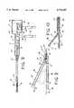
- FIG. 1is a perspective view of a clamp being applied by a clamp applier through a trocar to occlude a body conduit;
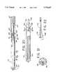
- FIG. 2is a axial cross-section view of one embodiment of the clamp illustrated in FIG. 1;
- FIG. 3is a axial cross-section view of one embodiment of the clamp applier illustrated in FIG. 1;
- FIG. 4is a axial cross-section view of the applier showing a rotatable shaft deployed to an extended position
- FIG. 5is a radial cross-section view taken along lines 5--5 of FIG. 3;
- FIG. 6is a perspective view of the clamp aligned for engagement by the rotatable shaft of the clamp applier
- FIG. 7is an elevation view of the proximal end of the clamp taken along lines 7--7 of FIG. 4;
- FIG. 8is an elevation view of the distal end of the clamp applier taken along lines 8--8 of FIG. 4;
- FIG. 9is a side view, partially in phantom, of the clamp operatively disposed on the clamp applier, and a handle operated to close the clamp;
- FIG. 10is a side view partially in phantom similar to FIG. 9 with the handle operated to open the jaws of the clamp;
- FIG. 11is a perspective view of the abdominal cavity illustrating the placement of outer clamps in a bowelectomy procedure
- FIG. 12is a perspective view similar to FIG. 11 showing the placement of inner clamps in the procedure
- FIG. 13is a perspective view similar to FIG. 11 illustrating the removal of a bowel section from the abdominal cavity;
- FIG. 14is a perspective view similar to FIG. 11 illustrating the suturing of the bowel following removal of the bowel section;
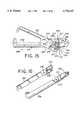
- FIG. 15is a perspective view of a second embodiment of the surgical clamp
- FIG. 16is a partially exploded view of the surgical clamp of the second preferred embodiment
- FIG. 17is a cross-sectional view of the clamp applier according to a second preferred embodiment of the present invention.
- FIG. 18is a top cross-sectional view of the clamp applier of the second preferred embodiment of the present invention.
- FIG. 19is a top cross-sectional view of both the surgical clamp and the clamp applier of the second preferred embodiment of the present invention.
- FIG. 20is a side cross-sectional view of the surgical clamp and the clamp applier of the second preferred embodiment of the present invention.
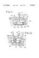
- FIG. 21is a cross-sectional view taken along line 21--21 of FIG. 20;
- FIG. 22is a side view of the pivoting arm and actuator spring of the clamp applier of the second embodiment of the present invention.
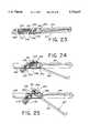
- FIGS. 23-25show the surgical clamp and the clamp applier of the second preferred embodiment in three sequential configurations.
- FIG. 1A surgical clamp and clamp applier are illustrated in FIG. 1 and designated respectively by the reference numerals 10 and 12.
- the clamp 10has a generally cylindrical configuration with an axis 14 extending between a proximal end 16 and a distal end 18.
- the clamp applier 12includes a housing 21 and a tube 23 which extends distally of the housing 21 along an axis 25.
- the tube 23 and the clamp 10are sized and configured to fit through a trocar 27 which has been positioned to provide access across the lapra or abdominal wall 30. Both the trocar 27 and the laparoscopic surgical procedure are described in greater detail in applicant's U.S. Pat. No. 5,209,737 issued on May 11, 1993 and entitled Lever Actuated Septum Seal.
- the clamp appliercan be operated to open and close the clamp 10 about a body conduit, such as a bowel 32.
- a body conduitsuch as a bowel 32.
- the clamp 10is illustrated in an axial cross-section view to include a supporting structure 34 and a pair of jaws 36 and 38.
- the jaw 36is formed as an extension of the supporting structure 34, while the jaw 38 is pivotal on the jaw 36 at a hinge 41.
- the jaws 36 and 38extend longitudinally toward the distal end 18 of the clamp 10 where one of the jaws, such as the jaw 38 is provided with an overhang 43. As the jaw 38 moves into proximity with the jaw 36, the overhang 43 encloses the bowel 32 prior to complete occlusion. This insures that the bowel 32 is captured between the jaws 36, 38 as the final occluding pressure is applied.
- the jaw 38At the proximal end of the jaw 38, distally of the supporting structure 34, the jaw 38 is provided with a beveled surface 45 which faces inwardly toward the axis 14 of the clamp 10. This surface 45 functions in a camming action with a screw 47 which is rotatable within the supporting structure 34.
- the screw 47is disposed for movement along the axis 14 of the clamp 10. As the screw 47 is rotated it moves axially through the supporting structure 34 to engage the beveled surface 45. Further axial movement of the screw 47 forces the jaw 38 to pivot on the hinge 41. This pivotal movement moves the jaw 38 from an open state illustrated in FIG. 2, wherein the jaw 38 is spaced from the jaw 36, to a closed state illustrated in FIG.
- the jaw 38is brought into proximity with the jaw 36.
- the body conduitsuch as the bowel 32, which is disposed between the jaws 36 and 38, is at least partially occluded.
- Soft inserts 49can be provided along the jaws 36 and 38 to reduce trauma to the bowel 32.
- a spring 52can be provided in the hinge 41 in order to bias the jaws 36 and 38 to the open position.
- the jaw 38will automatically separate from the jaw 36.
- the jaw 38moves toward the jaw 36 against the bias of the spring 52.
- both of the jaws 36 and 38are pivotal along the supporting structure 34 and include bevel surfaces, such as surface 45, which are engagable by the screw 47 to open and close the jaws 36, 38.
- annulus 54can be provided at the proximal end of the screw 47 in order to facilitate attachment to the clamp applier 12.
- the annulus 54preferably has an axis 55 which perpendicularly intersects the axis 14 of the clamp 10.
- the clamp applier 12is illustrated in the axial cross-section view of FIG. 3 which shows the interior regions of the housing 21 and the tube 23.
- the tube 23is attached to the distal end of the housing 21 where a distal wall 56 extends generally perpendicular to the axis 25.
- a shaft 58extends through the tube 23 and proximally through a hole 61 in the distal wall 56 into the housing 21.
- the shaft 58extends through a wafer 62 and terminates in the distal end of an aladdin screw 63.
- the diameter of the aladdin screw 63is decreased to define a proximal facing shoulder 65, increased to define a distally facing shoulder 67, and enlarged again at a distally facing shoulder 69 formed on a terminal lug 70.
- the aladdin screw 63has an outer cylindrical surface which is provided with counter-rotating spiral grooves 72 and 74.
- a trigger 81 pivotal on the housing 21operates a pair of fingers 83 and 85. These fingers are closely spaced to receive the reduced diameter of the aladdin screw 63 between the shoulders 65 and 67.
- a handle 90 fixed to the housing 21provides support, in the palm of a user's hand (not shown), against which the trigger 81 can be operated. Pulling the trigger causes the fingers 83, 85 to engage the proximally facing shoulder 65 and to move the aladdin screw 63 and associated shaft 58 distally as illustrated in FIG. 4.
- a compression spring 92 disposed therebetween around the shaft 58functions to bias the aladdin screw 63 and shaft 58 toward a proximal retracted position.
- This proximal positionis illustrated in FIG. 3 along with a locking mechanism which functions to maintain the screw 63 and the shaft 58 in the proximal position.
- the locking mechanismincludes a second trigger 96 and a pair of fingers 98 and 101 which engage the aladdin screw between the shoulders 67 and 69. In a preferred embodiment, these fingers 98, 101 extend perpendicular to the axis 25 and abut the distally facing shoulder 69 to hold the terminal lug 70 in a locked proximal position.
- the aladdin screw 63 and shaft 58are locked in the proximal position.
- the trigger 96is pulled against the handle 90 as illustrated in FIG. 4, the fingers 98 and 101 are removed from the terminal lug 70 to permit distal movement of the screw 63 and shaft 58.
- the trigger 96initially releases the lock as the trigger 81 deploys the screw 93 and shaft 58 to the distal extended position.
- the proximal and distal positions of the shaft 58are best described with reference to the distal end of the shaft 58 which is formed in the shape of a hook 110.
- the distal end of the hook 110includes a terminal portion 112 which extends generally perpendicular to the axis 25.
- the hook 110is sized and configured to engage the annulus 54 at the proximal end of the clamp 10.
- the hook 110 and shaft 58function as an engagement mechanism for initially engaging the clamp 10 and ultimately moving the clamp into operative disposition relative to the tube 23.
- the trigger 81functions to deploy this engaging mechanism to the distal position wherein the hook 110 extends beyond the end of the tube 23. In this position the terminal end 112 of the hook 110 is accessible for insertion into the annulus 54.
- FIG. 6the clamp 10 is illustrated in a free state wherein it is not attached to the clamp applier 12.
- the spring 92functions to move the shaft 58 and hook 110 to the proximal position drawing the annulus 54 of the clamp 10 into the tube 23. In a preferred embodiment, this brings the clamp 10 into abutting relationship with the distal end of the tube 23 wherein the axes 14 and 25 are aligned to facilitate insertion through the trocar 27.
- the clamp 10can be otherwise engaged by the shaft 58 of the applier 12 in a locking but operative position.
- the screw 47needs to be positively engaged by the shaft 58 so that the clamp 10 cannot be accidentally dropped into the abdominal cavity.
- This positive engagement between the clamp 10 and shaft 58must also be capable of transmitting the rotational movement of the shaft 58 to the screw 47.
- the supporting structure 34 of the clamp 10can be held against axial movement by the locking mechanism including the trigger 96.
- the supporting structure of the clamp 10is held against rotational movement relative to the tube 23 by a key 114 on the supporting structure 34 and associated key way 116 on the tube 23.
- the key 114is formed with four sides which are equally spaced around and inclined proximally toward the axis 14. This key 114 registers with similar surfaces which are formed on the inside of the tube 23 and define the key way 116.
- the supporting structure 34forms a proximally facing shoulder 118, best illustrated in FIG. 2. This shoulder 118 is adapted to register with a distal surface 121 on the tube 23.
- the key 114 and key way 116will be apparent. In general, it is desirable that the key 114 can be tapered inwardly, proximally in order to achieve axial alignment of the clamp 10 and tube 23. Any noncircular shape for the key 114 and key way 116 would appear to inhibit rotational movement between the clamp 10 and tube 23.
- the clamp 10When the clamp 10 is operatively disposed, the annulus 54 is engaged by the hook 110 interiorly of the tube 23.
- the key 114registers with the key way 116, and the shoulder 118 is in abutting relationship with the surface 121. With the proximal bias on the shaft 58, the clamp 10 is automatically moved to this operative position where it can be locked in place by operation of the trigger 96.
- a second handle 130can be provided on the housing 21 for engagement by the fingers of a user's hand.
- This handleis fixed to a follower block 132 which is movable along the housing 21 in cooperation with the aladdin screw 63.
- This follower block 132includes a follower 133 movable between two positions by operation of a tab 134 which is accessible outside the housing 21.
- the tab 134is operable to bring the follower 133 into registration with one of the grooves 72 and 74.
- movement of the handle 130 toward the handle 90causes the aladdin screw 63 to rotate in a clockwise direction.
- Thiscauses the shaft 58 to rotate in a clockwise direction and to advance the screw 47 of the clamp 10 toward the beveled surface 45.
- movement of the handle 130 toward the handle 90rotates the aladdin screw 63 in a counter-clockwise direction. This causes the shaft 58 to move counter-clockwise and the screw 47 to be withdrawn from the beveled surface 45 permitting the jaws 36, 38 to open.
- the aladdin screw 63 and associated follower 133, tab 134 and handle 130function so that the linear movement of the handle 130 is converted into rotational movement of the shaft 58.
- movement of the handle 130 in a single direction, toward the handle 90can produce either clockwise or counter-clockwise rotation of the shaft 58 depending on the position of the tab 134 and associated follower 133.
- the clamp 10is initially in a free state, unattached to the clamp applier 12.
- the shaft 58In order to prepare the applier 12 to receive the clamp 10, the shaft 58 initially must be unlocked. This requires that the trigger 96 be pulled against the handle 20 in order to remove the fingers 98, 101 from the shoulder 69 of the terminal lug 70. Thus operation of the trigger 96 elevates the fingers 98, 101 as illustrated in FIG. 4, to free the shaft 58 for axial movement along the axis 25.
- the shaft 58is biased in the retracted position so that operation of the trigger 81 is required to deploy the hook 110.
- the fingers 83, 85are brought into engagement with the shoulder 65. Further proximal movement of the trigger 81 moves the aladdin screw 63 and shaft 58 against the bias of the spring 92 to the extended position illustrated in FIG. 4.
- the terminal end 112 of the hook 110can be introduced through the annulus 54 to engage the clamp 10.
- the bias of the spring 92moves the shaft and aladdin screw 63 toward the retracted position.
- the hook 110is drawn into the tube 23 along with the annulus 54, and the key 114 on the clamp 10 registers with the key way 116 at the distal end of the tube 23.
- the shoulders 118abut the distal surface 121, the clamp 10 has achieved its operative position. It can be retained in this position by moving the trigger 96 distally so that the fingers 98, 101, engage the shoulder 69 on the terminal lug 70.
- registration of the key 114 and key way 116seeks to align the axis 14 of the clamp 10 with the axis 25 of the clamp applier 12.
- Axial movement of the clamp 10 relative to the applier 12is inhibited by the locking mechanism, while rotational movement of the clamp 10 relative to the applier 12 is inhibited by the registration of the key 114 and key way 116.
- the shaft 56can be rotated in two directions to either open or close the jaws 36, 38.
- operation of the handle 130 in a single directioncan cause rotation of the shaft 58 in either of the two directions.
- the tab 134is positioned so that the follower 133 engages the groove 74
- movement of the handle 130 toward the handle 90will be converted into clockwise rotation of the shaft 58.
- the screw 47to advance into the beveled surface 45 causing the jaws 36 and 38 as illustrated in FIG. 9.
- the follower 133engages the groove 72 of the aladdin screw 63.
- movement of the handle 130 toward the handle 90can be converted into rotational movement of the shaft 58 in the counter-clockwise direction. This will remove the screw 47 from the beveled surface 45 resulting in separation of the jaws 36, 38 by operation of the spring 52, as illustrated in FIG. 10.
- FIGS. 11-14wherein three sections of the bowel are designated consecutively by the reference numerals 32a, 32b and 32c. In this procedure, it is the center section 32b which is to be removed.
- a clamp 10ais engaged by the clamp applier 12 and inserted through the trocar 25 to operatively occlude the bowel between the section 32a and 32b.
- the applier 12can be operated to disengage the hook 110 from the associated annulus 54a.
- a second clamp 10bis operatively disposed to occlude the bowel between the section 32b and the section 32c.
- the clamp applier 12can be operated to release the hook 110 from the associated annulus 54b.
- retractors 136 and 138can be introduced through the abdominal wall 30 to engage the respective annulus 54a and 54b.
- the retractors 136, 138can be introduced through secondary trocars (not shown) similar to the trocar 25. Once the clamps 10a and 10b have been engaged by the respective retractors 136, 138, they can be moved toward the abdominal wall 30 to elevate the bowel 32 as illustrated in FIG. 12.
- two additional clamps 10c and 10dcan be attached to occlude the bowel 32 adjacent the respective clamps 10a and 10b. These clamps 10c and 10d can also be released and the clamp applier 12 removed from the trocar 25.
- the center section 32b of the bowel 32can be severed from the sections 32a and 32c by appropriate incisions between the clamp pairs 10a, 10c and 10d, 10b.
- the clamp applier 12can be reinserted through the trocar 25 to engage the clamps 10c and 10d and to remove these clamps through the trocar 25.
- a grasper 141may also be inserted to withdraw the central section 32b of the bowel, as illustrated in FIG. 13.
- a suturing mechanism(not shown) can be introduced through the trocar 12 to facilitate the placement of sutures 143 between the bowel portion 32a to the bowel portion 32c.
- the retractors 136, 138can be operated to disengage the clamps 10a, 10b, and the clamp applier 12 can be reintroduced to retrieve the clamps 10a, 10b.
- the retractors 136, 138 and the trocar 25are removed from the abdominal wall 30 to complete the procedure.
- FIGS. 15-25A second preferred embodiment of the clamp is illustrated in FIGS. 15-25.
- the surgical clamp 208comprises a first jaw 212 and a second jaw 214.
- the first jaw 212 and the second jaw 214preferably comprise injection molded plastic.
- the surgical clamp 208comprises a proximal end near an annulus 216, a distal end opposite the annulus 216, and a clamp axis 232 extending between the proximal end and the distal end.
- the annulus 216 of the surgical clamp 208is adapted for accommodating a hook 218 (FIG. 18).
- the hook 218pulls the proximal portion of the surgical clamp 208 into contact with a tube 223 (FIG. 18), which preferably comprises stainless steel and is similar to the tube 23 shown in FIG. 1, for example.
- a wedge 225 (FIG. 19) of the surgical clamp 208moves into contact with an incline 227 (FIG. 18), which is disposed within the tube 223.
- the close fit between the wedge 225 and the incline 227serves to align an axis 230 (FIG. 18) of the tube 223 with the clamp axis 232 and, further, prevents the surgical clamp 208 from rotating about either of these axes 230 and 232.
- the first jaw 212comprises a slot 234, which is formed between a fixed member 235 and a movable member 236.
- a pawl/spring assembly 237is secured to the fixed member 235 via a first fastener 238, and the movable member 236 is secured to the first jaw 212 via a pivot 239.
- the fixed member 235is integrally formed with the first jaw 212.
- a leaf spring 244allows the pawl 245 to move in and out of mesh with a ratchet 247 of the second jaw 214.
- the pawl 245is biased into mesh with the ratchet 247, but can be moved against this bias out of mesh with the ratchet 247.
- the movement of the pawl 245approximates a pivoting movement about the leaf spring 244, but other engaging and disengaging motions may also be used.
- the contacting protrusion 250is preferably integrally formed with the movable member 236, and is adapted to contact a receptor protrusion 251 of the pawl 245.
- Rotational movement of the movable member 236 about the pivot 239 in a counter-clockwise directionresults in the contacting protrusion 250 moving the pawl 245 against the bias of the leaf spring 244 via the receptor protrusion 251. Movement of the pawl 245 against the bias of the leaf spring 244 results in disengagement of the pawl 245 from the ratchet 247.
- FIG. 16shows the first jaw 212 disassembled from the second jaw 214.
- the first jaw 212is pivotally held to the second jaw 214 with a snap protrusion 240 of the first jaw 212 that fits into a snap aperture 242 of the second jaw 214.
- the teeth of the fixed ratchet 247are slanted in a clockwise direction.
- the teeth of the pawl 245 of the first jaw 212are also slanted in a clockwise direction.
- This orientation of the teeth of the fixed ratchet 247 and of the pawl 245allows the two sets of teeth 245 and 247 to slide upon one another when the first jaw 212 is moved toward the second jaw 214, but does not allow the two sets of teeth 245 and 247 to slide upon one another when the first jaw 212 is moved away from the second jaw 214.
- this slanting of the teeth 245 and 247allows the two jaws 212 and 214 to be shut, but does not allow the two jaws 212 and 214 to be opened.
- any force applied to the distal end 245should be in a general direction of the arrow A1. Further rotational movement of the movable member 236 continues to hold the pawl 245 out of mesh with the ratchet 247 and, additionally, results in movement of the first jaw 212 away from the second jaw 214.
- a pin 254fits within the slot 234. Movement of the pin 254 within the slot 234 in the direction of the arrow A1 results in the pin 254 contacting the movable member 236. This application of force by the pin 254 onto the movable member 236 results in disengagement of the pawl 245 and, subsequently, upon further force by the pin 254, results in movement of the first jaw 212 away from the second jaw 214. Movement of the pin within the slot 234 against the proximal end 251 of the movable member 236 results in the movable member 236 rotating in a clockwise direction to thereby move the contacting protrusion 250 away from the receptor protrusion 251.
- FIG. 17illustrates a clamp applier 210, which is used in conjunction with the surgical clamp 208.
- the clamp applier 210comprises the axis 230, which extends between a proximal end of the clamp applier 210 near the movable handle 270 and a distal end of the clamp applier 210 near a pivoting arm 272.
- FIG. 18illustrates a top view of the clamp applier 210.
- a usermoves the trigger 256 in the proximal direction toward the stationary handle 258, which is preferably integrally molded with the housing 257.
- the trigger 256rotates in a counter-clockwise direction about the first hinge 261, and causes the shaft 263 and the hook 218 to move forward in the distal direction.
- the hook 218is first inserted through the annulus 216 of the surgical clamp 208. Next, the user releases the trigger 256 which causes the spring-biased hook 218 to be retracted back into the tube 223. As the proximal end of the surgical clamp 208 is pulled into the tube 223, the wedge 225 of the surgical clamp 208 moves into contact with the incline 227.
- FIG. 19illustrates the registering of the wedge 225 of the surgical clamp 208 with the incline 227 of the clamp applier 210.
- the close fit between the wedge 225 and the incline 227serves to align the axis 230 of the clamp applier 210 with the clamp axis 232 and, further, prevents the surgical clamp 208 from rotating about either of these axes 230 and 232.
- a side view of the surgical clamp 208 and the clamp applier 210 of FIG. 19is shown in FIG. 20.
- the pin 254 of the clamp applier 210is automatically positioned within the slot 234.
- a cross section taken along the line 21--21 of FIG. 20is shown in FIG. 21.
- the pin 254initially fits within the slot 234, or comes into contact with one of the two ramps 264 disposed on opposite sides of the slot 234.
- One of the ramps 264comprises a surface of the fixed member 235 and other ramp comprises a surface of the movable member 236. If the pin 254 initially contacts one of the two ramps 264, then further movement of the surgical clamp 208 by the hook 218 causes the pin 254 to travel up the ramp 264 and into the slot 234. Since the actuator spring 278 is flexible in a direction normal to the channel 283 of the pivoting arm 271, as shown in FIG. 22, movement of the pin 254 up the ramp 264 does not break or damage the actuator spring 278.
- a rod 265connects the pivoting arm 272 to the movable handle 270.
- the stationary handle 258 and the movable handle 270together comprise a set of scissor handles, which is easy to operate with a single hand of the user. The user can move the movable handle 270 toward and away from the stationary handle 258 with ease.
- the pivoting arm 272which is pivotal in a vertical plane about a pivot hinge 276, has an actuator spring 278 secured thereto.
- the actuator spring 278is secured to the pivoting arm 272 with a single screw 281.
- the actuator spring 278comprises a leaf spring, which fits into a channel 283 of the pivoting arm 272.
- the channel 283 of the pivoting arm 272prevents the actuator spring 278 from moving in the vertical plane, except for when the pivoting arm 272 is also moved in the vertical plane.
- the actuator spring 278Since the actuator spring 278 is only secured to the channel 283 at the proximal end of the actuator spring 278, the actuator spring 278 is able to move slightly in a horizontal plane, which passes through the channel 283. Thus, the distal end of the actuator spring 278 is able to move away from the channel 283, but the proximal end of the actuator spring 278 is secured to the channel by the single screw 281.
- the positioning of the actuator spring 278, after movement away from the channel 283,is shown in phantom in FIG. 22 and denoted by the reference number 285. As the pivoting arm 272 is pivoted about the pivot hinge 276, the actuator spring 278 also pivots about the pivot hinge 276. The actuator spring 278 remains in or directly above the channel 283 of the pivoting arm 272 during this movement.
- the rod 265is moved distally in the direction of the arrow A2.
- the distal movement of the rod 265results in rotation of the pivoting arm 272 in the counter-clockwise direction (clockwise direction in FIG. 17) about the pivot hinge 276.
- This rotation of the pivoting arm 272causes the proximal portion of the pivoting arm 272, which is connected to the rod 265, to move downward and to issue through a slot in the tube 223.
- the tube 223may be configured to surround only the incline 227 and the shaft 263, but not the pivoting arm 272 and the actuator spring 278.
- a distal end 273 of the rod 265travels within a track 275.
- the track 275facilitates rotation of the pivoting arm 272 by the rod 265, without requiring the rod 265 to bend, for example.
- FIG. 24illustrates the distal end 273 of the rod 265 in an intermediate portion of the track 275, corresponding to an intermediate orientation of the pivoting arm 272.
- an initial rotation of the pivoting arm 272 in the counter-clockwise directionresults in movement of the movable member 236 in a counter-clockwise direction about the pivot 239.
- the movable member 236is thus moved from an initial first configuration, shown in FIG. 23, to a second configuration where the first jaw 212 and the second jaw 214 are still closed but the pawl 245 is no longer in mesh with the ratchet 247.
- FIG. 24illustrates the rotational movement of the movable member 236, where the pawl 245 is no longer in mesh with the ratchet 247, and where the first jaw 212 and the second jaw 214 are somewhat opened.
- the movable member 236is shown in FIG. 24 in the third configuration, where the first jaw 212 and the second jaw 214 are opened.
- the first jaw 212 and the second jaw 214are shown in a completely open position, which comprises 35 degrees in the presently preferred embodiment.
- the pin 254has moved from the distal end 245 (FIG. 23), to an intermediate location between the distal end 245 and the proximal end 251 (FIG. 24), and finally to the proximal end 251 of the movable member 236. Movement of the pin 254 to the proximal end 251 of the movable member 236 applies a rotational force onto the movable member 236, to thereby rotate the movable member 236 back into the first configuration, where the teeth of the pawl 245 are in mesh with the teeth of the ratchet 247.
- the rod 265is moved in a proximal direction. Subsequent movement of the rod 265 in the proximal direction results in movement of the first jaw 212 and the second jaw 214 together, as the teeth of the pawl 245 slide against the teeth of the ratchet 247. Thus, proximal movement of the rod 265 results in rotation of the pivoting arm 272 in the counter-clockwise direction about the pivot hinge 276, which causes the pin 254 of the actuator spring 278 to move in a downward direction. This downward movement of the pin 254 results in movement of the first jaw 212 toward the second jaw 214.
- the surgical clamp 208 and clamp applier 210can be used similarly to the surgical clamp 10 and clamp applier 12, as discussed above with reference to FIGS. 11-14, for example.
- clamp configurationscan be adapted to provide a generally cylindrical configuration with jaws openable and closeable by operation of a mechanism generally along the axis of the clamp, or by movement of a mechanism in a direction normal to the axis of the clamp.
- the clampcan be introduced through a trocar to facilitate a wide variation in laparoscopic procedures.
- both apparatus and methods for operating such a clamp with an appropriate clamp applierwill also be apparent.
- the appliermust have an elongate configuration also sized and configured to fit through a trocar.
- An appropriate mechanism for holding the clamp in a fixed operable positionwill be desirable. Once the clamp is in this position, an appropriate mechanism will open and close the jaws of the clamp.
Landscapes
- Health & Medical Sciences (AREA)
- Surgery (AREA)
- Life Sciences & Earth Sciences (AREA)
- Heart & Thoracic Surgery (AREA)
- Nuclear Medicine, Radiotherapy & Molecular Imaging (AREA)
- Vascular Medicine (AREA)
- Engineering & Computer Science (AREA)
- Biomedical Technology (AREA)
- Reproductive Health (AREA)
- Medical Informatics (AREA)
- Molecular Biology (AREA)
- Animal Behavior & Ethology (AREA)
- General Health & Medical Sciences (AREA)
- Public Health (AREA)
- Veterinary Medicine (AREA)
- Surgical Instruments (AREA)
Abstract
Description
Claims (21)
Priority Applications (1)
| Application Number | Priority Date | Filing Date | Title |
|---|---|---|---|
| US08/727,773US5776147A (en) | 1993-10-20 | 1996-10-08 | Laparoscopic surgical clamp |
Applications Claiming Priority (3)
| Application Number | Priority Date | Filing Date | Title |
|---|---|---|---|
| US08/139,919US5496333A (en) | 1993-10-20 | 1993-10-20 | Laparoscopic surgical clamp |
| US08/674,925US5776146A (en) | 1993-10-20 | 1996-07-03 | Laparoscopic surgical clamp |
| US08/727,773US5776147A (en) | 1993-10-20 | 1996-10-08 | Laparoscopic surgical clamp |
Related Parent Applications (1)
| Application Number | Title | Priority Date | Filing Date |
|---|---|---|---|
| US08/674,925Continuation-In-PartUS5776146A (en) | 1993-10-20 | 1996-07-03 | Laparoscopic surgical clamp |
Publications (1)
| Publication Number | Publication Date |
|---|---|
| US5776147Atrue US5776147A (en) | 1998-07-07 |
Family
ID=26837670
Family Applications (1)
| Application Number | Title | Priority Date | Filing Date |
|---|---|---|---|
| US08/727,773Expired - LifetimeUS5776147A (en) | 1993-10-20 | 1996-10-08 | Laparoscopic surgical clamp |
Country Status (1)
| Country | Link |
|---|---|
| US (1) | US5776147A (en) |
Cited By (190)
| Publication number | Priority date | Publication date | Assignee | Title |
|---|---|---|---|---|
| US20020123529A1 (en)* | 1995-05-22 | 2002-09-05 | Hoechst Aktiengesellschaft | Fluorophenyl-substituted alkenylcarboxylic acid guanidides, process for their preparation, their use as a medicament or diagnostic, and medicament containing them |
| US20020188220A1 (en)* | 2001-06-12 | 2002-12-12 | Jacek Krzyzanowski | Method of assembling a non-metallic biopsy forceps jaw and a non-metallic biopsy forceps jaw |
| US20030184071A1 (en)* | 2002-03-28 | 2003-10-02 | Sanyo Electric Co., Ltd. | Mobile carriage |
| US20030212435A1 (en)* | 2002-03-26 | 2003-11-13 | Adam Gold | Handleless clamping device |
| US20050240075A1 (en)* | 2001-10-05 | 2005-10-27 | Scimed Life Systems, Inc. | Expandable surgical implants and methods of using them |
| US6974462B2 (en) | 2001-12-19 | 2005-12-13 | Boston Scientific Scimed, Inc. | Surgical anchor implantation device |
| US20060089525A1 (en)* | 2004-06-14 | 2006-04-27 | Boston Scientific Scimed, Inc. | Systems, methods and devices relating to implantable supportive slings |
| EP1709915A1 (en) | 2005-04-07 | 2006-10-11 | Schnorrenberg Chirurgiemechanik GmbH | Surgical clip for laparoscopic procedures |
| US20060229596A1 (en)* | 2005-04-06 | 2006-10-12 | Boston Scientific Scimed, Inc. | Systems, devices, and methods for treating pelvic floor disorders |
| US20060235444A1 (en)* | 2005-04-14 | 2006-10-19 | Ethicon Endo-Surgery, Inc. | Clip advancer mechanism with alignment features |
| US20060235442A1 (en)* | 2005-04-14 | 2006-10-19 | Ethicon Endo-Surgery, Inc. | Clip applier with migrational resistance features |
| US20070015953A1 (en)* | 2005-07-13 | 2007-01-18 | Boston Scientific Scimed, Inc. | Snap fit sling anchor system and related methods |
| US20070021649A1 (en)* | 2005-07-25 | 2007-01-25 | Boston Scientific Scimed, Inc | Elastic sling system and related methods |
| US7261724B2 (en) | 2005-04-14 | 2007-08-28 | Ethicon Endo-Surgery, Inc. | Surgical clip advancement mechanism |
| US7288098B2 (en) | 2005-04-14 | 2007-10-30 | Ethicon Endo-Surgery, Inc. | Force limiting mechanism for medical instrument |
| US7297149B2 (en) | 2005-04-14 | 2007-11-20 | Ethicon Endo-Surgery, Inc. | Surgical clip applier methods |
| US20090014002A1 (en)* | 2005-04-14 | 2009-01-15 | Honeywell International Inc. | Air filter assembly |
| US20090222029A1 (en)* | 2006-10-03 | 2009-09-03 | Udi Gordin | Clip for assisting surgical procedures |
| US7637917B2 (en) | 2004-10-08 | 2009-12-29 | Tyco Healthcare Group Lp | Endoscopic surgical clip applier |
| US20100050142A1 (en)* | 2004-07-22 | 2010-02-25 | Juergen Dirks | Special engineering change order cells |
| US7686820B2 (en) | 2005-04-14 | 2010-03-30 | Ethicon Endo-Surgery, Inc. | Surgical clip applier ratchet mechanism |
| US7731724B2 (en) | 2005-04-14 | 2010-06-08 | Ethicon Endo-Surgery, Inc. | Surgical clip advancement and alignment mechanism |
| US7743960B2 (en)* | 2002-06-14 | 2010-06-29 | Power Medical Interventions, Llc | Surgical device |
| US7819886B2 (en) | 2004-10-08 | 2010-10-26 | Tyco Healthcare Group Lp | Endoscopic surgical clip applier |
| US20110046437A1 (en)* | 2009-08-24 | 2011-02-24 | Cvdevices, Llc | Tissue restoration devices, systems, and methods |
| US7918230B2 (en) | 2007-09-21 | 2011-04-05 | Tyco Healthcare Group Lp | Surgical device having a rotatable jaw portion |
| US20110087242A1 (en)* | 2009-10-13 | 2011-04-14 | Tyco Healthcare Group Lp | Suture clip applier |
| US7963433B2 (en) | 2007-09-21 | 2011-06-21 | Tyco Healthcare Group Lp | Surgical device having multiple drivers |
| GB2476461A (en)* | 2009-12-22 | 2011-06-29 | Neosurgical Ltd | Laparoscopic surgical device with jaws biased closed |
| US8038686B2 (en) | 2005-04-14 | 2011-10-18 | Ethicon Endo-Surgery, Inc. | Clip applier configured to prevent clip fallout |
| US8056565B2 (en) | 2008-08-25 | 2011-11-15 | Tyco Healthcare Group Lp | Surgical clip applier and method of assembly |
| US8128643B2 (en) | 2006-10-17 | 2012-03-06 | Tyco Healthcare Group Lp | Apparatus for applying surgical clips |
| US8128644B2 (en) | 2000-12-07 | 2012-03-06 | Integrated Vascular Systems, Inc. | Closure device and methods for making and using them |
| US8182497B2 (en) | 2000-12-07 | 2012-05-22 | Integrated Vascular Systems, Inc. | Closure device |
| US8192459B2 (en) | 2002-06-04 | 2012-06-05 | Abbott Vascular Inc. | Blood vessel closure clip and delivery device |
| US8202294B2 (en) | 2003-01-30 | 2012-06-19 | Integrated Vascular Systems, Inc. | Clip applier and methods of use |
| US8202283B2 (en) | 2002-12-31 | 2012-06-19 | Integrated Vascular Systems, Inc. | Methods for manufacturing a clip and clip |
| US8202293B2 (en) | 2003-01-30 | 2012-06-19 | Integrated Vascular Systems, Inc. | Clip applier and methods of use |
| US8226681B2 (en) | 2007-06-25 | 2012-07-24 | Abbott Laboratories | Methods, devices, and apparatus for managing access through tissue |
| US8262679B2 (en) | 2009-10-09 | 2012-09-11 | Ethicon Endo-Surgery, Inc. | Clip advancer |
| US8267945B2 (en) | 2009-10-09 | 2012-09-18 | Ethicon Endo-Surgery, Inc. | Clip advancer with lockout mechanism |
| US8267944B2 (en) | 2008-08-29 | 2012-09-18 | Tyco Healthcare Group Lp | Endoscopic surgical clip applier with lock out |
| WO2012083187A3 (en)* | 2010-12-16 | 2012-09-20 | University Of South Florida | Laparoscopic tool for grasping tissue |
| US8303624B2 (en) | 2010-03-15 | 2012-11-06 | Abbott Cardiovascular Systems, Inc. | Bioabsorbable plug |
| US8313497B2 (en) | 2005-07-01 | 2012-11-20 | Abbott Laboratories | Clip applier and methods of use |
| US8323312B2 (en) | 2008-12-22 | 2012-12-04 | Abbott Laboratories | Closure device |
| US8382773B2 (en) | 2007-03-26 | 2013-02-26 | Covidien Lp | Endoscopic surgical clip applier |
| US8398676B2 (en) | 2008-10-30 | 2013-03-19 | Abbott Vascular Inc. | Closure device |
| US8398656B2 (en) | 2003-01-30 | 2013-03-19 | Integrated Vascular Systems, Inc. | Clip applier and methods of use |
| US8403946B2 (en) | 2010-07-28 | 2013-03-26 | Covidien Lp | Articulating clip applier cartridge |
| US8403945B2 (en) | 2010-02-25 | 2013-03-26 | Covidien Lp | Articulating endoscopic surgical clip applier |
| US8409223B2 (en) | 2008-08-29 | 2013-04-02 | Covidien Lp | Endoscopic surgical clip applier with clip retention |
| US8409222B2 (en) | 2004-10-08 | 2013-04-02 | Covidien Lp | Endoscopic surgical clip applier |
| DE102011119348A1 (en) | 2011-11-25 | 2013-05-29 | Olympus Winter & Ibe Gmbh | Surgical clip for clamping body intestine during surgical operation, has actuator that includes drive elements which are rotatably operated for closing movable jaws against fixed jaw of clamping device |
| US8465502B2 (en) | 2008-08-25 | 2013-06-18 | Covidien Lp | Surgical clip applier and method of assembly |
| US8506580B2 (en) | 2007-04-11 | 2013-08-13 | Covidien Lp | Surgical clip applier |
| US8545486B2 (en) | 2009-12-15 | 2013-10-01 | Covidien Lp | Surgical clip applier |
| US8556930B2 (en) | 2006-06-28 | 2013-10-15 | Abbott Laboratories | Vessel closure device |
| US8579932B2 (en) | 2002-02-21 | 2013-11-12 | Integrated Vascular Systems, Inc. | Sheath apparatus and methods for delivering a closure device |
| US8585717B2 (en) | 2008-08-29 | 2013-11-19 | Covidien Lp | Single stroke endoscopic surgical clip applier |
| US8590760B2 (en) | 2004-05-25 | 2013-11-26 | Abbott Vascular Inc. | Surgical stapler |
| US8597325B2 (en) | 2000-12-07 | 2013-12-03 | Integrated Vascular Systems, Inc. | Apparatus and methods for providing tactile feedback while delivering a closure device |
| US8603116B2 (en) | 2010-08-04 | 2013-12-10 | Abbott Cardiovascular Systems, Inc. | Closure device with long tines |
| US8672953B2 (en) | 2007-12-17 | 2014-03-18 | Abbott Laboratories | Tissue closure system and methods of use |
| US8690910B2 (en) | 2000-12-07 | 2014-04-08 | Integrated Vascular Systems, Inc. | Closure device and methods for making and using them |
| US8728119B2 (en) | 2001-06-07 | 2014-05-20 | Abbott Vascular Inc. | Surgical staple |
| US8758396B2 (en) | 2000-01-05 | 2014-06-24 | Integrated Vascular Systems, Inc. | Vascular sheath with bioabsorbable puncture site closure apparatus and methods of use |
| US8758400B2 (en) | 2000-01-05 | 2014-06-24 | Integrated Vascular Systems, Inc. | Closure system and methods of use |
| US8758399B2 (en) | 2010-08-02 | 2014-06-24 | Abbott Cardiovascular Systems, Inc. | Expandable bioabsorbable plug apparatus and method |
| US8758398B2 (en) | 2006-09-08 | 2014-06-24 | Integrated Vascular Systems, Inc. | Apparatus and method for delivering a closure element |
| US8784447B2 (en) | 2000-09-08 | 2014-07-22 | Abbott Vascular Inc. | Surgical stapler |
| US8808310B2 (en) | 2006-04-20 | 2014-08-19 | Integrated Vascular Systems, Inc. | Resettable clip applier and reset tools |
| US8820602B2 (en) | 2007-12-18 | 2014-09-02 | Abbott Laboratories | Modular clip applier |
| US8821534B2 (en) | 2010-12-06 | 2014-09-02 | Integrated Vascular Systems, Inc. | Clip applier having improved hemostasis and methods of use |
| US8858594B2 (en) | 2008-12-22 | 2014-10-14 | Abbott Laboratories | Curved closure device |
| US8893947B2 (en) | 2007-12-17 | 2014-11-25 | Abbott Laboratories | Clip applier and methods of use |
| US8900253B2 (en) | 2003-03-11 | 2014-12-02 | Covidien Lp | Clip applying apparatus with angled jaw |
| US8905937B2 (en) | 2009-02-26 | 2014-12-09 | Integrated Vascular Systems, Inc. | Methods and apparatus for locating a surface of a body lumen |
| US8926656B2 (en) | 2003-01-30 | 2015-01-06 | Integated Vascular Systems, Inc. | Clip applier and methods of use |
| US8926633B2 (en) | 2005-06-24 | 2015-01-06 | Abbott Laboratories | Apparatus and method for delivering a closure element |
| US8956388B2 (en) | 2000-01-05 | 2015-02-17 | Integrated Vascular Systems, Inc. | Integrated vascular device with puncture site closure component and sealant |
| US8968337B2 (en) | 2010-07-28 | 2015-03-03 | Covidien Lp | Articulating clip applier |
| US9011464B2 (en) | 2010-11-02 | 2015-04-21 | Covidien Lp | Self-centering clip and jaw |
| US9089311B2 (en) | 2009-01-09 | 2015-07-28 | Abbott Vascular Inc. | Vessel closure devices and methods |
| US9089674B2 (en) | 2000-10-06 | 2015-07-28 | Integrated Vascular Systems, Inc. | Apparatus and methods for positioning a vascular sheath |
| US9113892B2 (en) | 2013-01-08 | 2015-08-25 | Covidien Lp | Surgical clip applier |
| US9113991B2 (en) | 2011-05-12 | 2015-08-25 | Boston Scientific Scimed, Inc. | Anchors for bodily implants and methods for anchoring bodily implants into a patient's body |
| US9149276B2 (en) | 2011-03-21 | 2015-10-06 | Abbott Cardiovascular Systems, Inc. | Clip and deployment apparatus for tissue closure |
| US9173644B2 (en) | 2009-01-09 | 2015-11-03 | Abbott Vascular Inc. | Closure devices, systems, and methods |
| US9186136B2 (en) | 2009-12-09 | 2015-11-17 | Covidien Lp | Surgical clip applier |
| US9186153B2 (en) | 2011-01-31 | 2015-11-17 | Covidien Lp | Locking cam driver and jaw assembly for clip applier |
| US9282965B2 (en)* | 2008-05-16 | 2016-03-15 | Abbott Laboratories | Apparatus and methods for engaging tissue |
| US9314230B2 (en) | 2009-01-09 | 2016-04-19 | Abbott Vascular Inc. | Closure device with rapidly eroding anchor |
| US9332976B2 (en) | 2011-11-30 | 2016-05-10 | Abbott Cardiovascular Systems, Inc. | Tissue closure device |
| US9358015B2 (en) | 2008-08-29 | 2016-06-07 | Covidien Lp | Endoscopic surgical clip applier with wedge plate |
| US9364209B2 (en) | 2012-12-21 | 2016-06-14 | Abbott Cardiovascular Systems, Inc. | Articulating suturing device |
| US9364239B2 (en) | 2011-12-19 | 2016-06-14 | Covidien Lp | Jaw closure mechanism for a surgical clip applier |
| US9364216B2 (en) | 2011-12-29 | 2016-06-14 | Covidien Lp | Surgical clip applier with integrated clip counter |
| US9370400B2 (en) | 2011-10-19 | 2016-06-21 | Ethicon Endo-Surgery, Inc. | Clip applier adapted for use with a surgical robot |
| US9402757B2 (en) | 2009-08-24 | 2016-08-02 | Cvdevices, Llc | Devices, systems and methods for tissue restoration |
| US9408610B2 (en) | 2012-05-04 | 2016-08-09 | Covidien Lp | Surgical clip applier with dissector |
| US9414844B2 (en) | 2008-08-25 | 2016-08-16 | Covidien Lp | Surgical clip appliers |
| US9414824B2 (en) | 2009-01-16 | 2016-08-16 | Abbott Vascular Inc. | Closure devices, systems, and methods |
| US9414820B2 (en) | 2009-01-09 | 2016-08-16 | Abbott Vascular Inc. | Closure devices, systems, and methods |
| US9456824B2 (en) | 2011-09-15 | 2016-10-04 | Teleflex Medical Incorporated | Manual surgical ligation clip applier |
| US9486191B2 (en) | 2009-01-09 | 2016-11-08 | Abbott Vascular, Inc. | Closure devices |
| US9532787B2 (en) | 2012-05-31 | 2017-01-03 | Covidien Lp | Endoscopic clip applier |
| US9579091B2 (en) | 2000-01-05 | 2017-02-28 | Integrated Vascular Systems, Inc. | Closure system and methods of use |
| US9585647B2 (en) | 2009-08-26 | 2017-03-07 | Abbott Laboratories | Medical device for repairing a fistula |
| US9636201B2 (en) | 2011-05-12 | 2017-05-02 | Boston Scientific Scimed, Inc. | Delivery members for delivering an implant into a body of a patient |
| US9675436B2 (en) | 2005-07-25 | 2017-06-13 | Boston Scientific Scimed, Inc. | Pelvic floor repair system |
| US9687247B2 (en) | 2004-10-08 | 2017-06-27 | Covidien Lp | Apparatus for applying surgical clips |
| US9750500B2 (en) | 2013-01-18 | 2017-09-05 | Covidien Lp | Surgical clip applier |
| US9763668B2 (en) | 2004-10-08 | 2017-09-19 | Covidien Lp | Endoscopic surgical clip applier |
| US9775623B2 (en) | 2011-04-29 | 2017-10-03 | Covidien Lp | Surgical clip applier including clip relief feature |
| US9775624B2 (en) | 2013-08-27 | 2017-10-03 | Covidien Lp | Surgical clip applier |
| US9901335B2 (en)* | 2014-07-10 | 2018-02-27 | Maxwell Choongwon Park | Method and apparatus for securing soft tissue to bone |
| US9931124B2 (en) | 2015-01-07 | 2018-04-03 | Covidien Lp | Reposable clip applier |
| US9968362B2 (en) | 2013-01-08 | 2018-05-15 | Covidien Lp | Surgical clip applier |
| US9980841B2 (en) | 2009-08-24 | 2018-05-29 | Cvdevices, Llc | Devices and systems configured to fit around a tissue using the same |
| US10159491B2 (en) | 2015-03-10 | 2018-12-25 | Covidien Lp | Endoscopic reposable surgical clip applier |
| CN109078251A (en)* | 2018-06-21 | 2018-12-25 | 中国人民解放军陆军军医大学第二附属医院 | A kind of dual peacetime ERCP clamp device |
| US10292712B2 (en) | 2015-01-28 | 2019-05-21 | Covidien Lp | Surgical clip applier with integrated cutter |
| US10390831B2 (en) | 2015-11-10 | 2019-08-27 | Covidien Lp | Endoscopic reposable surgical clip applier |
| US10426489B2 (en) | 2016-11-01 | 2019-10-01 | Covidien Lp | Endoscopic reposable surgical clip applier |
| US10492795B2 (en) | 2016-11-01 | 2019-12-03 | Covidien Lp | Endoscopic surgical clip applier |
| US10548602B2 (en) | 2017-02-23 | 2020-02-04 | Covidien Lp | Endoscopic surgical clip applier |
| US10582931B2 (en) | 2016-02-24 | 2020-03-10 | Covidien Lp | Endoscopic reposable surgical clip applier |
| US10603038B2 (en) | 2017-02-22 | 2020-03-31 | Covidien Lp | Surgical clip applier including inserts for jaw assembly |
| US10610236B2 (en) | 2016-11-01 | 2020-04-07 | Covidien Lp | Endoscopic reposable surgical clip applier |
| US10639044B2 (en) | 2016-10-31 | 2020-05-05 | Covidien Lp | Ligation clip module and clip applier |
| US10639032B2 (en) | 2017-06-30 | 2020-05-05 | Covidien Lp | Endoscopic surgical clip applier including counter assembly |
| USD884170S1 (en)* | 2018-04-03 | 2020-05-12 | Karl Storz Se & Co. Kg | Clamp for laparoscopic sleeve gastrectomy |
| USD884891S1 (en)* | 2018-04-03 | 2020-05-19 | Karl Storz Se & Co. Kg | Clamp for laparoscopic sleeve gastrectomy |
| US10653429B2 (en) | 2017-09-13 | 2020-05-19 | Covidien Lp | Endoscopic surgical clip applier |
| US10660725B2 (en) | 2017-02-14 | 2020-05-26 | Covidien Lp | Endoscopic surgical clip applier including counter assembly |
| US10660723B2 (en) | 2017-06-30 | 2020-05-26 | Covidien Lp | Endoscopic reposable surgical clip applier |
| US10660651B2 (en) | 2016-10-31 | 2020-05-26 | Covidien Lp | Endoscopic reposable surgical clip applier |
| US10675043B2 (en) | 2017-05-04 | 2020-06-09 | Covidien Lp | Reposable multi-fire surgical clip applier |
| US10675112B2 (en) | 2017-08-07 | 2020-06-09 | Covidien Lp | Endoscopic surgical clip applier including counter assembly |
| US10702278B2 (en) | 2014-12-02 | 2020-07-07 | Covidien Lp | Laparoscopic surgical ligation clip applier |
| US10702279B2 (en) | 2015-11-03 | 2020-07-07 | Covidien Lp | Endoscopic surgical clip applier |
| US10702280B2 (en) | 2015-11-10 | 2020-07-07 | Covidien Lp | Endoscopic reposable surgical clip applier |
| US10709455B2 (en) | 2017-02-02 | 2020-07-14 | Covidien Lp | Endoscopic surgical clip applier |
| US10722236B2 (en) | 2017-12-12 | 2020-07-28 | Covidien Lp | Endoscopic reposable surgical clip applier |
| US10722235B2 (en) | 2017-05-11 | 2020-07-28 | Covidien Lp | Spring-release surgical clip |
| US10743887B2 (en) | 2017-12-13 | 2020-08-18 | Covidien Lp | Reposable multi-fire surgical clip applier |
| US10758245B2 (en) | 2017-09-13 | 2020-09-01 | Covidien Lp | Clip counting mechanism for surgical clip applier |
| US10758244B2 (en) | 2017-02-06 | 2020-09-01 | Covidien Lp | Endoscopic surgical clip applier |
| US10765431B2 (en) | 2016-01-18 | 2020-09-08 | Covidien Lp | Endoscopic surgical clip applier |
| US10786273B2 (en) | 2018-07-13 | 2020-09-29 | Covidien Lp | Rotation knob assemblies for handle assemblies |
| US10786262B2 (en) | 2017-08-09 | 2020-09-29 | Covidien Lp | Endoscopic reposable surgical clip applier |
| US10786263B2 (en) | 2017-08-15 | 2020-09-29 | Covidien Lp | Endoscopic reposable surgical clip applier |
| US10806463B2 (en) | 2011-11-21 | 2020-10-20 | Covidien Lp | Surgical clip applier |
| US10806464B2 (en) | 2016-08-11 | 2020-10-20 | Covidien Lp | Endoscopic surgical clip applier and clip applying systems |
| US10828036B2 (en) | 2017-11-03 | 2020-11-10 | Covidien Lp | Endoscopic surgical clip applier and handle assemblies for use therewith |
| US10835260B2 (en) | 2017-09-13 | 2020-11-17 | Covidien Lp | Endoscopic surgical clip applier and handle assemblies for use therewith |
| US10835341B2 (en) | 2017-09-12 | 2020-11-17 | Covidien Lp | Endoscopic surgical clip applier and handle assemblies for use therewith |
| US10849630B2 (en) | 2017-12-13 | 2020-12-01 | Covidien Lp | Reposable multi-fire surgical clip applier |
| US10863992B2 (en) | 2017-08-08 | 2020-12-15 | Covidien Lp | Endoscopic surgical clip applier |
| US10905425B2 (en) | 2015-11-10 | 2021-02-02 | Covidien Lp | Endoscopic reposable surgical clip applier |
| US10932793B2 (en) | 2016-01-11 | 2021-03-02 | Covidien Lp | Endoscopic reposable surgical clip applier |
| US10932790B2 (en) | 2017-08-08 | 2021-03-02 | Covidien Lp | Geared actuation mechanism and surgical clip applier including the same |
| US10932791B2 (en) | 2017-11-03 | 2021-03-02 | Covidien Lp | Reposable multi-fire surgical clip applier |
| US10945734B2 (en) | 2017-11-03 | 2021-03-16 | Covidien Lp | Rotation knob assemblies and surgical instruments including the same |
| US10959737B2 (en) | 2017-12-13 | 2021-03-30 | Covidien Lp | Reposable multi-fire surgical clip applier |
| US10993721B2 (en) | 2018-04-25 | 2021-05-04 | Covidien Lp | Surgical clip applier |
| US11033256B2 (en) | 2018-08-13 | 2021-06-15 | Covidien Lp | Linkage assembly for reusable surgical handle assemblies |
| US11051828B2 (en) | 2018-08-13 | 2021-07-06 | Covidien Lp | Rotation knob assemblies and surgical instruments including same |
| US11051827B2 (en) | 2018-01-16 | 2021-07-06 | Covidien Lp | Endoscopic surgical instrument and handle assemblies for use therewith |
| US11058432B2 (en) | 2015-01-15 | 2021-07-13 | Covidien Lp | Endoscopic reposable surgical clip applier |
| US11071553B2 (en) | 2016-08-25 | 2021-07-27 | Covidien Lp | Endoscopic surgical clip applier and clip applying systems |
| US11116513B2 (en) | 2017-11-03 | 2021-09-14 | Covidien Lp | Modular surgical clip cartridge |
| US11116514B2 (en) | 2017-02-06 | 2021-09-14 | Covidien Lp | Surgical clip applier with user feedback feature |
| US11147566B2 (en) | 2018-10-01 | 2021-10-19 | Covidien Lp | Endoscopic surgical clip applier |
| US11219463B2 (en) | 2018-08-13 | 2022-01-11 | Covidien Lp | Bilateral spring for surgical instruments and surgical instruments including the same |
| US11246601B2 (en) | 2018-08-13 | 2022-02-15 | Covidien Lp | Elongated assemblies for surgical clip appliers and surgical clip appliers incorporating the same |
| US11253267B2 (en) | 2018-08-13 | 2022-02-22 | Covidien Lp | Friction reduction mechanisms for handle assemblies |
| US11259887B2 (en) | 2018-08-10 | 2022-03-01 | Covidien Lp | Feedback mechanisms for handle assemblies |
| US11278267B2 (en) | 2018-08-13 | 2022-03-22 | Covidien Lp | Latch assemblies and surgical instruments including the same |
| US11344316B2 (en) | 2018-08-13 | 2022-05-31 | Covidien Lp | Elongated assemblies for surgical clip appliers and surgical clip appliers incorporating the same |
| US11376015B2 (en) | 2017-11-03 | 2022-07-05 | Covidien Lp | Endoscopic surgical clip applier and handle assemblies for use therewith |
| US11524398B2 (en) | 2019-03-19 | 2022-12-13 | Covidien Lp | Gear drive mechanisms for surgical instruments |
| US11583291B2 (en) | 2017-02-23 | 2023-02-21 | Covidien Lp | Endoscopic surgical clip applier |
| US11596428B2 (en) | 2018-11-15 | 2023-03-07 | Applied Medical Resources Corporation | Laparoscopic grasper with force-limiting grasping mechanism |
| US20230073110A1 (en)* | 2021-09-06 | 2023-03-09 | Drew Schembre | Endoscopic closure device |
| US11723669B2 (en) | 2020-01-08 | 2023-08-15 | Covidien Lp | Clip applier with clip cartridge interface |
| US11779340B2 (en) | 2020-01-02 | 2023-10-10 | Covidien Lp | Ligation clip loading device |
| US12114866B2 (en) | 2020-03-26 | 2024-10-15 | Covidien Lp | Interoperative clip loading device |
| US12419648B2 (en) | 2022-09-26 | 2025-09-23 | Covidien Lp | Two-part fasteners for surgical clip appliers and surgical clip appliers for deploying the same |
Citations (5)
| Publication number | Priority date | Publication date | Assignee | Title |
|---|---|---|---|---|
| US3510923A (en)* | 1968-06-20 | 1970-05-12 | American Hospital Supply Corp | Parallel jaw ratchet clip and retractor |
| US3882854A (en)* | 1973-08-23 | 1975-05-13 | Research Corp | Surgical clip and applicator |
| US3955249A (en)* | 1973-07-05 | 1976-05-11 | Hiromitsu Shiozaki | Clamping device |
| US4064881A (en)* | 1975-06-06 | 1977-12-27 | Rocket Of London Limited | Surgical clip applicator |
| US4169476A (en)* | 1977-08-12 | 1979-10-02 | Wolf Medical Instruments Corporation | Applicator for surgical clip |
- 1996
- 1996-10-08USUS08/727,773patent/US5776147A/ennot_activeExpired - Lifetime
Patent Citations (5)
| Publication number | Priority date | Publication date | Assignee | Title |
|---|---|---|---|---|
| US3510923A (en)* | 1968-06-20 | 1970-05-12 | American Hospital Supply Corp | Parallel jaw ratchet clip and retractor |
| US3955249A (en)* | 1973-07-05 | 1976-05-11 | Hiromitsu Shiozaki | Clamping device |
| US3882854A (en)* | 1973-08-23 | 1975-05-13 | Research Corp | Surgical clip and applicator |
| US4064881A (en)* | 1975-06-06 | 1977-12-27 | Rocket Of London Limited | Surgical clip applicator |
| US4169476A (en)* | 1977-08-12 | 1979-10-02 | Wolf Medical Instruments Corporation | Applicator for surgical clip |
Cited By (368)
| Publication number | Priority date | Publication date | Assignee | Title |
|---|---|---|---|---|
| US20020123529A1 (en)* | 1995-05-22 | 2002-09-05 | Hoechst Aktiengesellschaft | Fluorophenyl-substituted alkenylcarboxylic acid guanidides, process for their preparation, their use as a medicament or diagnostic, and medicament containing them |
| US9050087B2 (en) | 2000-01-05 | 2015-06-09 | Integrated Vascular Systems, Inc. | Integrated vascular device with puncture site closure component and sealant and methods of use |
| US9579091B2 (en) | 2000-01-05 | 2017-02-28 | Integrated Vascular Systems, Inc. | Closure system and methods of use |
| US10111664B2 (en) | 2000-01-05 | 2018-10-30 | Integrated Vascular Systems, Inc. | Closure system and methods of use |
| US8758396B2 (en) | 2000-01-05 | 2014-06-24 | Integrated Vascular Systems, Inc. | Vascular sheath with bioabsorbable puncture site closure apparatus and methods of use |
| US8758400B2 (en) | 2000-01-05 | 2014-06-24 | Integrated Vascular Systems, Inc. | Closure system and methods of use |
| US8956388B2 (en) | 2000-01-05 | 2015-02-17 | Integrated Vascular Systems, Inc. | Integrated vascular device with puncture site closure component and sealant |
| US9402625B2 (en) | 2000-09-08 | 2016-08-02 | Abbott Vascular Inc. | Surgical stapler |
| US8784447B2 (en) | 2000-09-08 | 2014-07-22 | Abbott Vascular Inc. | Surgical stapler |
| US9060769B2 (en) | 2000-09-08 | 2015-06-23 | Abbott Vascular Inc. | Surgical stapler |
| US9089674B2 (en) | 2000-10-06 | 2015-07-28 | Integrated Vascular Systems, Inc. | Apparatus and methods for positioning a vascular sheath |
| US8597325B2 (en) | 2000-12-07 | 2013-12-03 | Integrated Vascular Systems, Inc. | Apparatus and methods for providing tactile feedback while delivering a closure device |
| US8182497B2 (en) | 2000-12-07 | 2012-05-22 | Integrated Vascular Systems, Inc. | Closure device |
| US9554786B2 (en) | 2000-12-07 | 2017-01-31 | Integrated Vascular Systems, Inc. | Closure device and methods for making and using them |
| US8128644B2 (en) | 2000-12-07 | 2012-03-06 | Integrated Vascular Systems, Inc. | Closure device and methods for making and using them |
| US10245013B2 (en) | 2000-12-07 | 2019-04-02 | Integrated Vascular Systems, Inc. | Closure device and methods for making and using them |
| US8690910B2 (en) | 2000-12-07 | 2014-04-08 | Integrated Vascular Systems, Inc. | Closure device and methods for making and using them |
| US8257390B2 (en) | 2000-12-07 | 2012-09-04 | Integrated Vascular Systems, Inc. | Closure device and methods for making and using them |
| US8236026B2 (en) | 2000-12-07 | 2012-08-07 | Integrated Vascular Systems, Inc. | Closure device and methods for making and using them |
| US8486108B2 (en) | 2000-12-07 | 2013-07-16 | Integrated Vascular Systems, Inc. | Closure device and methods for making and using them |
| US8603136B2 (en) | 2000-12-07 | 2013-12-10 | Integrated Vascular Systems, Inc. | Apparatus and methods for providing tactile feedback while delivering a closure device |
| US9320522B2 (en) | 2000-12-07 | 2016-04-26 | Integrated Vascular Systems, Inc. | Closure device and methods for making and using them |
| US9585646B2 (en) | 2000-12-07 | 2017-03-07 | Integrated Vascular Systems, Inc. | Closure device and methods for making and using them |
| US8486092B2 (en) | 2000-12-07 | 2013-07-16 | Integrated Vascular Systems, Inc. | Closure device and methods for making and using them |
| US8728119B2 (en) | 2001-06-07 | 2014-05-20 | Abbott Vascular Inc. | Surgical staple |
| US20020188220A1 (en)* | 2001-06-12 | 2002-12-12 | Jacek Krzyzanowski | Method of assembling a non-metallic biopsy forceps jaw and a non-metallic biopsy forceps jaw |
| US6792663B2 (en)* | 2001-06-12 | 2004-09-21 | Jacek Krzyzanowski | Method of assembling a non-metallic biopsy forceps jaw |
| US20090076318A1 (en)* | 2001-10-05 | 2009-03-19 | Boston Scientific Scimed, Inc. | Expandable surgical implants and methods of using them |
| US7465270B2 (en) | 2001-10-05 | 2008-12-16 | Boston Scientific Scimed, Inc. | Expandable surgical implants and methods of using them |
| US20050240075A1 (en)* | 2001-10-05 | 2005-10-27 | Scimed Life Systems, Inc. | Expandable surgical implants and methods of using them |
| US8376928B2 (en) | 2001-10-05 | 2013-02-19 | Boston Scientific Scimed, Inc. | Expandable surgical implants and methods of using them |
| US6974462B2 (en) | 2001-12-19 | 2005-12-13 | Boston Scientific Scimed, Inc. | Surgical anchor implantation device |
| US10201340B2 (en) | 2002-02-21 | 2019-02-12 | Integrated Vascular Systems, Inc. | Sheath apparatus and methods for delivering a closure device |
| US8579932B2 (en) | 2002-02-21 | 2013-11-12 | Integrated Vascular Systems, Inc. | Sheath apparatus and methods for delivering a closure device |
| US9498196B2 (en) | 2002-02-21 | 2016-11-22 | Integrated Vascular Systems, Inc. | Sheath apparatus and methods for delivering a closure device |
| US7588585B2 (en) | 2002-03-26 | 2009-09-15 | Novare Surgical Systems, Inc. | Handleless clamping device |
| US9782174B2 (en) | 2002-03-26 | 2017-10-10 | Intuitive Surgical Operations, Inc. | Handleless clamping device |
| US8361108B2 (en) | 2002-03-26 | 2013-01-29 | Intuitive Surgical Operations, Inc. | Handleless clamping device |
| US20090093842A1 (en)* | 2002-03-26 | 2009-04-09 | Novare Surgical Systems, Inc. | Handleless clamping device |
| US11439394B2 (en) | 2002-03-26 | 2022-09-13 | Intuitive Surgical Operations, Inc. | Handleless clamping device |
| US20090093841A1 (en)* | 2002-03-26 | 2009-04-09 | Novare Surgical Systems, Inc. | Handleless clamping device |
| US20090093828A1 (en)* | 2002-03-26 | 2009-04-09 | Novare Surgical Systems, Inc. | Handleless clamping device |
| US10702272B2 (en) | 2002-03-26 | 2020-07-07 | Intuitive Surgical Operations, Inc. | Handleless clamping device |
| WO2003082129A3 (en)* | 2002-03-26 | 2004-06-10 | Novare Surgical Systems Inc | Handleless clamping device |
| US8506590B2 (en) | 2002-03-26 | 2013-08-13 | Intuitive Surgical Operations, Inc. | Handleless clamping device |
| US20030212435A1 (en)* | 2002-03-26 | 2003-11-13 | Adam Gold | Handleless clamping device |
| US20030184071A1 (en)* | 2002-03-28 | 2003-10-02 | Sanyo Electric Co., Ltd. | Mobile carriage |
| US9980728B2 (en) | 2002-06-04 | 2018-05-29 | Abbott Vascular Inc | Blood vessel closure clip and delivery device |
| US8192459B2 (en) | 2002-06-04 | 2012-06-05 | Abbott Vascular Inc. | Blood vessel closure clip and delivery device |
| US9295469B2 (en) | 2002-06-04 | 2016-03-29 | Abbott Vascular Inc. | Blood vessel closure clip and delivery device |
| US8469995B2 (en) | 2002-06-04 | 2013-06-25 | Abbott Vascular Inc. | Blood vessel closure clip and delivery device |
| US8540733B2 (en) | 2002-06-14 | 2013-09-24 | Covidien Lp | Surgical method and device having a first jaw and a second jaw in opposed correspondence for clamping, cutting, and stapling tissue |
| US7743960B2 (en)* | 2002-06-14 | 2010-06-29 | Power Medical Interventions, Llc | Surgical device |
| US9861362B2 (en) | 2002-06-14 | 2018-01-09 | Covidien Lp | Surgical device |
| US8056786B2 (en) | 2002-06-14 | 2011-11-15 | Tyco Healthcare Group Lp | Surgical device |
| US8585836B2 (en) | 2002-12-31 | 2013-11-19 | Integrated Vascular Systems, Inc. | Methods for manufacturing a clip and clip |
| US8202283B2 (en) | 2002-12-31 | 2012-06-19 | Integrated Vascular Systems, Inc. | Methods for manufacturing a clip and clip |
| US11589856B2 (en) | 2003-01-30 | 2023-02-28 | Integrated Vascular Systems, Inc. | Clip applier and methods of use |
| US8398656B2 (en) | 2003-01-30 | 2013-03-19 | Integrated Vascular Systems, Inc. | Clip applier and methods of use |
| US8926656B2 (en) | 2003-01-30 | 2015-01-06 | Integated Vascular Systems, Inc. | Clip applier and methods of use |
| US8529587B2 (en) | 2003-01-30 | 2013-09-10 | Integrated Vascular Systems, Inc. | Methods of use of a clip applier |
| US8202293B2 (en) | 2003-01-30 | 2012-06-19 | Integrated Vascular Systems, Inc. | Clip applier and methods of use |
| US8202294B2 (en) | 2003-01-30 | 2012-06-19 | Integrated Vascular Systems, Inc. | Clip applier and methods of use |
| US9271707B2 (en) | 2003-01-30 | 2016-03-01 | Integrated Vascular Systems, Inc. | Clip applier and methods of use |
| US10398418B2 (en) | 2003-01-30 | 2019-09-03 | Integrated Vascular Systems, Inc. | Clip applier and methods of use |
| US9398914B2 (en) | 2003-01-30 | 2016-07-26 | Integrated Vascular Systems, Inc. | Methods of use of a clip applier |
| US9968361B2 (en) | 2003-03-11 | 2018-05-15 | Covidien Lp | Clip applying apparatus with angled jaw |
| US8900253B2 (en) | 2003-03-11 | 2014-12-02 | Covidien Lp | Clip applying apparatus with angled jaw |
| US8590760B2 (en) | 2004-05-25 | 2013-11-26 | Abbott Vascular Inc. | Surgical stapler |
| US8628465B2 (en) | 2004-06-14 | 2014-01-14 | Boston Scientific Scimed, Inc. | Systems, methods and devices relating to implantable supportive slings |
| US10219885B2 (en) | 2004-06-14 | 2019-03-05 | Boston Scientific Scimed, Inc. | Systems, methods and devices relating to implantable supportive slings |
| US20060089525A1 (en)* | 2004-06-14 | 2006-04-27 | Boston Scientific Scimed, Inc. | Systems, methods and devices relating to implantable supportive slings |
| US11918447B2 (en) | 2004-06-14 | 2024-03-05 | Boston Scientific Scimed, Inc. | Systems, methods and devices relating to implantable supportive slings |
| US20100050142A1 (en)* | 2004-07-22 | 2010-02-25 | Juergen Dirks | Special engineering change order cells |
| US7905890B2 (en) | 2004-10-08 | 2011-03-15 | Tyco Healthcare Group Lp | Endoscopic surgical clip applier |
| US9763668B2 (en) | 2004-10-08 | 2017-09-19 | Covidien Lp | Endoscopic surgical clip applier |
| US7637917B2 (en) | 2004-10-08 | 2009-12-29 | Tyco Healthcare Group Lp | Endoscopic surgical clip applier |
| US8357171B2 (en) | 2004-10-08 | 2013-01-22 | Covidien Lp | Endoscopic surgical clip applier |
| US7819886B2 (en) | 2004-10-08 | 2010-10-26 | Tyco Healthcare Group Lp | Endoscopic surgical clip applier |
| US9011465B2 (en) | 2004-10-08 | 2015-04-21 | Covidien Lp | Endoscopic surgical clip applier |
| US8282655B2 (en) | 2004-10-08 | 2012-10-09 | Tyco Healthcare Group Lp | Endoscopic surgical clip applier |
| US8579918B2 (en) | 2004-10-08 | 2013-11-12 | Covidien Lp | Endoscopic surgical clip applier |
| US8267946B2 (en) | 2004-10-08 | 2012-09-18 | Tyco Healthcare Group Lp | Endoscopic surgical clip applier |
| US9364240B2 (en) | 2004-10-08 | 2016-06-14 | Covidien Lp | Endoscopic surgical clip applier |
| US10349950B2 (en) | 2004-10-08 | 2019-07-16 | Covidien Lp | Apparatus for applying surgical clips |
| US10485538B2 (en) | 2004-10-08 | 2019-11-26 | Covidien Lp | Endoscopic surgical clip applier |
| US8409222B2 (en) | 2004-10-08 | 2013-04-02 | Covidien Lp | Endoscopic surgical clip applier |
| US9687247B2 (en) | 2004-10-08 | 2017-06-27 | Covidien Lp | Apparatus for applying surgical clips |
| US20060229493A1 (en)* | 2005-04-06 | 2006-10-12 | Boston Scientific Scimed, Inc. | Systems, devices, and methods for sub-urethral support |
| US9022920B2 (en) | 2005-04-06 | 2015-05-05 | Boston Scientific Scimed, Inc. | Systems, devices, and methods for sub-urethral support |
| US8016741B2 (en) | 2005-04-06 | 2011-09-13 | Boston Scientific Scimed, Inc. | Systems, devices, and methods for sub-urethral support |
| US20060229596A1 (en)* | 2005-04-06 | 2006-10-12 | Boston Scientific Scimed, Inc. | Systems, devices, and methods for treating pelvic floor disorders |
| EP1709915A1 (en) | 2005-04-07 | 2006-10-11 | Schnorrenberg Chirurgiemechanik GmbH | Surgical clip for laparoscopic procedures |
| US8821516B2 (en) | 2005-04-14 | 2014-09-02 | Ethicon Endo-Surgery, Inc. | Clip applier with migrational resistance features |
| US9782181B2 (en) | 2005-04-14 | 2017-10-10 | Ethicon Llc | Surgical clip applier methods |
| US10639045B2 (en) | 2005-04-14 | 2020-05-05 | Ethicon Llc | Clip applier with clip follower |
| US8216257B2 (en) | 2005-04-14 | 2012-07-10 | Ethicon Endo-Surgery, Inc. | Clip applier configured to prevent clip fallout |
| US8915930B2 (en) | 2005-04-14 | 2014-12-23 | Ethicon Endo-Surgery, Inc. | Force limiting mechanism for medical instrument |
| US20060235444A1 (en)* | 2005-04-14 | 2006-10-19 | Ethicon Endo-Surgery, Inc. | Clip advancer mechanism with alignment features |
| US8523882B2 (en) | 2005-04-14 | 2013-09-03 | Ethicon Endo-Surgery, Inc. | Clip advancer mechanism with alignment features |
| US8075571B2 (en) | 2005-04-14 | 2011-12-13 | Ethicon Endo-Surgery, Inc. | Surgical clip applier methods |
| US10667824B2 (en) | 2005-04-14 | 2020-06-02 | Ethicon Llc | Surgical clip applier methods |
| US20060235442A1 (en)* | 2005-04-14 | 2006-10-19 | Ethicon Endo-Surgery, Inc. | Clip applier with migrational resistance features |
| US9717504B2 (en) | 2005-04-14 | 2017-08-01 | Ethicon Llc | Clip applier with migrational resistance features |
| US8246635B2 (en) | 2005-04-14 | 2012-08-21 | Ethicon Endo-Surgery, Inc. | Clip applier with migrational resistance features |
| US8038686B2 (en) | 2005-04-14 | 2011-10-18 | Ethicon Endo-Surgery, Inc. | Clip applier configured to prevent clip fallout |
| US8236012B2 (en) | 2005-04-14 | 2012-08-07 | Ethicon Endo-Surgery, Inc. | Surgical clip advancement mechanism |
| US7261724B2 (en) | 2005-04-14 | 2007-08-28 | Ethicon Endo-Surgery, Inc. | Surgical clip advancement mechanism |
| US7288098B2 (en) | 2005-04-14 | 2007-10-30 | Ethicon Endo-Surgery, Inc. | Force limiting mechanism for medical instrument |
| US20090014002A1 (en)* | 2005-04-14 | 2009-01-15 | Honeywell International Inc. | Air filter assembly |
| US7297149B2 (en) | 2005-04-14 | 2007-11-20 | Ethicon Endo-Surgery, Inc. | Surgical clip applier methods |
| US20080004639A1 (en)* | 2005-04-14 | 2008-01-03 | Ethicon Endo-Surgery, Inc. | Force limiting mechanism for medical instrument |
| US8753356B2 (en) | 2005-04-14 | 2014-06-17 | Ethicon Endo-Surgery, Inc. | Surgical clip applier methods |
| US8328822B2 (en) | 2005-04-14 | 2012-12-11 | Ethicon Endo-Surgery, Inc. | Surgical clip applier ratchet mechanism |
| US7740641B2 (en) | 2005-04-14 | 2010-06-22 | Ethicon Endo-Surgery, Inc. | Clip applier with migrational resistance features |
| US7731724B2 (en) | 2005-04-14 | 2010-06-08 | Ethicon Endo-Surgery, Inc. | Surgical clip advancement and alignment mechanism |
| US7686820B2 (en) | 2005-04-14 | 2010-03-30 | Ethicon Endo-Surgery, Inc. | Surgical clip applier ratchet mechanism |
| US8246634B2 (en) | 2005-04-14 | 2012-08-21 | Ethicon Endo-Surgery, Inc. | Surgical clip applier ratchet mechanism |
| US8926633B2 (en) | 2005-06-24 | 2015-01-06 | Abbott Laboratories | Apparatus and method for delivering a closure element |
| US11344304B2 (en) | 2005-07-01 | 2022-05-31 | Abbott Laboratories | Clip applier and methods of use |
| US8518057B2 (en) | 2005-07-01 | 2013-08-27 | Abbott Laboratories | Clip applier and methods of use |
| US10085753B2 (en) | 2005-07-01 | 2018-10-02 | Abbott Laboratories | Clip applier and methods of use |
| US8313497B2 (en) | 2005-07-01 | 2012-11-20 | Abbott Laboratories | Clip applier and methods of use |
| US12070214B2 (en) | 2005-07-01 | 2024-08-27 | Abbott Laboratories | Clip applier and methods of use |
| US9050068B2 (en) | 2005-07-01 | 2015-06-09 | Abbott Laboratories | Clip applier and methods of use |
| US9107659B2 (en) | 2005-07-13 | 2015-08-18 | Boston Scientific Scimed, Inc. | Snap fit sling anchor system and related methods |
| US20070015953A1 (en)* | 2005-07-13 | 2007-01-18 | Boston Scientific Scimed, Inc. | Snap fit sling anchor system and related methods |
| US8043205B2 (en) | 2005-07-13 | 2011-10-25 | Boston Scientific Scimed, Inc. | Snap fit sling anchor system |
| US9675436B2 (en) | 2005-07-25 | 2017-06-13 | Boston Scientific Scimed, Inc. | Pelvic floor repair system |
| US7981023B2 (en) | 2005-07-25 | 2011-07-19 | Boston Scientific Scimed, Inc. | Elastic sling system and related methods |
| US20070021649A1 (en)* | 2005-07-25 | 2007-01-25 | Boston Scientific Scimed, Inc | Elastic sling system and related methods |
| US10251738B2 (en) | 2005-07-25 | 2019-04-09 | Boston Scientific Scimed, Inc. | Pelvic floor repair system |
| US8777834B2 (en) | 2005-07-25 | 2014-07-15 | Boston Scientific Scimed, Inc. | Elastic sling system and related methods |
| US8808310B2 (en) | 2006-04-20 | 2014-08-19 | Integrated Vascular Systems, Inc. | Resettable clip applier and reset tools |
| US8556930B2 (en) | 2006-06-28 | 2013-10-15 | Abbott Laboratories | Vessel closure device |
| US9962144B2 (en) | 2006-06-28 | 2018-05-08 | Abbott Laboratories | Vessel closure device |
| US8758398B2 (en) | 2006-09-08 | 2014-06-24 | Integrated Vascular Systems, Inc. | Apparatus and method for delivering a closure element |
| US20090222029A1 (en)* | 2006-10-03 | 2009-09-03 | Udi Gordin | Clip for assisting surgical procedures |
| US8945155B2 (en)* | 2006-10-03 | 2015-02-03 | Virtual Ports Ltd. | Clip for assisting surgical procedures |
| US8128643B2 (en) | 2006-10-17 | 2012-03-06 | Tyco Healthcare Group Lp | Apparatus for applying surgical clips |
| US10166027B2 (en) | 2006-10-17 | 2019-01-01 | Covidien Lp | Apparatus for applying surgical clips |
| US9480477B2 (en) | 2006-10-17 | 2016-11-01 | Covidien Lp | Apparatus for applying surgical clips |
| US8603109B2 (en) | 2006-10-17 | 2013-12-10 | Covidien Lp | Apparatus for applying surgical clips |
| US9398917B2 (en) | 2007-03-26 | 2016-07-26 | Covidien Lp | Endoscopic surgical clip applier |
| US8382773B2 (en) | 2007-03-26 | 2013-02-26 | Covidien Lp | Endoscopic surgical clip applier |
| US8747423B2 (en) | 2007-03-26 | 2014-06-10 | Covidien Lp | Endoscopic surgical clip applier |
| US10363045B2 (en) | 2007-03-26 | 2019-07-30 | Covidien Lp | Endoscopic surgical clip applier |
| US10258346B2 (en) | 2007-04-11 | 2019-04-16 | Covidien Lp | Surgical clip applier |
| US9498227B2 (en) | 2007-04-11 | 2016-11-22 | Covidien Lp | Surgical clip applier |
| US8506580B2 (en) | 2007-04-11 | 2013-08-13 | Covidien Lp | Surgical clip applier |
| US8226681B2 (en) | 2007-06-25 | 2012-07-24 | Abbott Laboratories | Methods, devices, and apparatus for managing access through tissue |
| US7918230B2 (en) | 2007-09-21 | 2011-04-05 | Tyco Healthcare Group Lp | Surgical device having a rotatable jaw portion |
| US10881397B2 (en) | 2007-09-21 | 2021-01-05 | Covidien Lp | Surgical device having a rotatable jaw portion |
| US10420548B2 (en) | 2007-09-21 | 2019-09-24 | Covidien Lp | Surgical device having multiple drivers |
| US8272554B2 (en) | 2007-09-21 | 2012-09-25 | Tyco Healthcare Group Lp | Surgical device having multiple drivers |
| US8342379B2 (en) | 2007-09-21 | 2013-01-01 | Covidien Lp | Surgical device having multiple drivers |
| US7992758B2 (en) | 2007-09-21 | 2011-08-09 | Tyco Healthcare Group Lp | Surgical device having a rotatable jaw portion |
| US9017371B2 (en) | 2007-09-21 | 2015-04-28 | Covidien Lp | Surgical device having multiple drivers |
| US10117651B2 (en) | 2007-09-21 | 2018-11-06 | Covidien Lp | Surgical device having a rotatable jaw portion |
| US8752748B2 (en) | 2007-09-21 | 2014-06-17 | Covidien Lp | Surgical device having a rotatable jaw portion |
| US8353440B2 (en) | 2007-09-21 | 2013-01-15 | Covidien Lp | Surgical device having a rotatable jaw portion |
| US11317909B2 (en) | 2007-09-21 | 2022-05-03 | Covidien Lp | Surgical device having multiple drivers |
| US9282961B2 (en) | 2007-09-21 | 2016-03-15 | Covidien Lp | Surgical device having multiple drivers |
| US7963433B2 (en) | 2007-09-21 | 2011-06-21 | Tyco Healthcare Group Lp | Surgical device having multiple drivers |
| US9204877B2 (en) | 2007-09-21 | 2015-12-08 | Covidien Lp | Surgical device having a rotatable jaw portion |
| US8672953B2 (en) | 2007-12-17 | 2014-03-18 | Abbott Laboratories | Tissue closure system and methods of use |
| US8893947B2 (en) | 2007-12-17 | 2014-11-25 | Abbott Laboratories | Clip applier and methods of use |
| US8820602B2 (en) | 2007-12-18 | 2014-09-02 | Abbott Laboratories | Modular clip applier |
| US9282965B2 (en)* | 2008-05-16 | 2016-03-15 | Abbott Laboratories | Apparatus and methods for engaging tissue |
| US10413295B2 (en) | 2008-05-16 | 2019-09-17 | Abbott Laboratories | Engaging element for engaging tissue |
| US8465502B2 (en) | 2008-08-25 | 2013-06-18 | Covidien Lp | Surgical clip applier and method of assembly |
| US9549741B2 (en) | 2008-08-25 | 2017-01-24 | Covidien Lp | Surgical clip applier and method of assembly |
| US10542999B2 (en) | 2008-08-25 | 2020-01-28 | Covidien Lp | Surgical clip applier and method of assembly |
| US11510682B2 (en) | 2008-08-25 | 2022-11-29 | Covidien Lp | Surgical clip applier and method of assembly |
| US9414844B2 (en) | 2008-08-25 | 2016-08-16 | Covidien Lp | Surgical clip appliers |
| US8336556B2 (en) | 2008-08-25 | 2012-12-25 | Covidien Lp | Surgical clip applier and method of assembly |
| US8056565B2 (en) | 2008-08-25 | 2011-11-15 | Tyco Healthcare Group Lp | Surgical clip applier and method of assembly |
| US9358011B2 (en) | 2008-08-29 | 2016-06-07 | Covidien Lp | Endoscopic surgical clip applier with connector plate |
| US10159484B2 (en) | 2008-08-29 | 2018-12-25 | Covidien Lp | Endoscopic surgical clip applier with connector plate |
| US11806021B2 (en) | 2008-08-29 | 2023-11-07 | Covidien Lp | Endoscopic surgical clip applier with wedge plate |
| US10682135B2 (en) | 2008-08-29 | 2020-06-16 | Covidien Lp | Endoscopic surgical clip applier |
| US8409223B2 (en) | 2008-08-29 | 2013-04-02 | Covidien Lp | Endoscopic surgical clip applier with clip retention |
| US8267944B2 (en) | 2008-08-29 | 2012-09-18 | Tyco Healthcare Group Lp | Endoscopic surgical clip applier with lock out |
| US9089334B2 (en) | 2008-08-29 | 2015-07-28 | Covidien Lp | Endoscopic surgical clip applier with connector plate |
| US8486091B2 (en) | 2008-08-29 | 2013-07-16 | Covidien Lp | Endoscopic surgical clip applier |
| US8491608B2 (en) | 2008-08-29 | 2013-07-23 | Covidien Lp | Endoscopic surgical clip applier with clip retention |
| US9113893B2 (en) | 2008-08-29 | 2015-08-25 | Covidien Lp | Endoscopic surgical clip applier with clip retention |
| US9358015B2 (en) | 2008-08-29 | 2016-06-07 | Covidien Lp | Endoscopic surgical clip applier with wedge plate |
| US11213298B2 (en) | 2008-08-29 | 2022-01-04 | Covidien Lp | Endoscopic surgical clip applier with wedge plate |
| US8419752B2 (en) | 2008-08-29 | 2013-04-16 | Covidien Lp | Endoscopic surgical clip applier with connector plate |
| US9439654B2 (en) | 2008-08-29 | 2016-09-13 | Covidien Lp | Endoscopic surgical clip applier |
| US10231735B2 (en) | 2008-08-29 | 2019-03-19 | Covidien Lp | Endoscopic surgical clip applier |
| US10231738B2 (en) | 2008-08-29 | 2019-03-19 | Covidien Lp | Endoscopic surgical clip applier with wedge plate |
| US9545254B2 (en) | 2008-08-29 | 2017-01-17 | Covidien Lp | Endoscopic surgical clip applier with connector plate |
| US8585717B2 (en) | 2008-08-29 | 2013-11-19 | Covidien Lp | Single stroke endoscopic surgical clip applier |
| US8894665B2 (en) | 2008-08-29 | 2014-11-25 | Covidien Lp | Endoscopic surgical clip applier |
| US8657852B2 (en) | 2008-10-30 | 2014-02-25 | Abbott Vascular Inc. | Closure device |
| US8398676B2 (en) | 2008-10-30 | 2013-03-19 | Abbott Vascular Inc. | Closure device |
| US9241696B2 (en) | 2008-10-30 | 2016-01-26 | Abbott Vascular Inc. | Closure device |
| US8323312B2 (en) | 2008-12-22 | 2012-12-04 | Abbott Laboratories | Closure device |
| US8858594B2 (en) | 2008-12-22 | 2014-10-14 | Abbott Laboratories | Curved closure device |
| US9414820B2 (en) | 2009-01-09 | 2016-08-16 | Abbott Vascular Inc. | Closure devices, systems, and methods |
| US12383247B2 (en) | 2009-01-09 | 2025-08-12 | Abbott Vascular, Inc. | Closure devices and methods |
| US9314230B2 (en) | 2009-01-09 | 2016-04-19 | Abbott Vascular Inc. | Closure device with rapidly eroding anchor |
| US9089311B2 (en) | 2009-01-09 | 2015-07-28 | Abbott Vascular Inc. | Vessel closure devices and methods |
| US10537313B2 (en) | 2009-01-09 | 2020-01-21 | Abbott Vascular, Inc. | Closure devices and methods |
| US11439378B2 (en) | 2009-01-09 | 2022-09-13 | Abbott Cardiovascular Systems, Inc. | Closure devices and methods |
| US9173644B2 (en) | 2009-01-09 | 2015-11-03 | Abbott Vascular Inc. | Closure devices, systems, and methods |
| US9486191B2 (en) | 2009-01-09 | 2016-11-08 | Abbott Vascular, Inc. | Closure devices |
| US9414824B2 (en) | 2009-01-16 | 2016-08-16 | Abbott Vascular Inc. | Closure devices, systems, and methods |
| US8905937B2 (en) | 2009-02-26 | 2014-12-09 | Integrated Vascular Systems, Inc. | Methods and apparatus for locating a surface of a body lumen |
| US9089391B2 (en)* | 2009-08-24 | 2015-07-28 | Cvdevices, Llc | Tissue restoration devices, systems, and methods |
| US9402757B2 (en) | 2009-08-24 | 2016-08-02 | Cvdevices, Llc | Devices, systems and methods for tissue restoration |
| US20110046437A1 (en)* | 2009-08-24 | 2011-02-24 | Cvdevices, Llc | Tissue restoration devices, systems, and methods |
| US11103375B2 (en) | 2009-08-24 | 2021-08-31 | Cvdevices, Llc | Devices and systems configured to fit around a tissue or organ and methods of the same |
| US10390984B2 (en) | 2009-08-24 | 2019-08-27 | Cvdevices, Llc | Gastric devices, systems, and methods |
| US9980841B2 (en) | 2009-08-24 | 2018-05-29 | Cvdevices, Llc | Devices and systems configured to fit around a tissue using the same |
| US9585647B2 (en) | 2009-08-26 | 2017-03-07 | Abbott Laboratories | Medical device for repairing a fistula |
| US8267945B2 (en) | 2009-10-09 | 2012-09-18 | Ethicon Endo-Surgery, Inc. | Clip advancer with lockout mechanism |
| US8262679B2 (en) | 2009-10-09 | 2012-09-11 | Ethicon Endo-Surgery, Inc. | Clip advancer |
| US8496673B2 (en) | 2009-10-09 | 2013-07-30 | Ethicon Endo-Surgery, Inc. | Clip advancer with lockout mechanism |
| US20110087242A1 (en)* | 2009-10-13 | 2011-04-14 | Tyco Healthcare Group Lp | Suture clip applier |
| US8734469B2 (en)* | 2009-10-13 | 2014-05-27 | Covidien Lp | Suture clip applier |
| US10758234B2 (en) | 2009-12-09 | 2020-09-01 | Covidien Lp | Surgical clip applier |
| US10004502B2 (en) | 2009-12-09 | 2018-06-26 | Covidien Lp | Surgical clip applier |
| US9186136B2 (en) | 2009-12-09 | 2015-11-17 | Covidien Lp | Surgical clip applier |
| US10470765B2 (en) | 2009-12-15 | 2019-11-12 | Covidien Lp | Surgical clip applier |
| US9526501B2 (en) | 2009-12-15 | 2016-12-27 | Covidien Lp | Surgical clip applier |
| US8545486B2 (en) | 2009-12-15 | 2013-10-01 | Covidien Lp | Surgical clip applier |
| GB2476461A (en)* | 2009-12-22 | 2011-06-29 | Neosurgical Ltd | Laparoscopic surgical device with jaws biased closed |
| US11213299B2 (en) | 2010-02-25 | 2022-01-04 | Covidien Lp | Articulating endoscopic surgical clip applier |
| US9393024B2 (en) | 2010-02-25 | 2016-07-19 | Covidien Lp | Articulating endoscopic surgical clip applier |
| US8845659B2 (en) | 2010-02-25 | 2014-09-30 | Covidien Lp | Articulating endoscopic surgical clip applier |
| US8403945B2 (en) | 2010-02-25 | 2013-03-26 | Covidien Lp | Articulating endoscopic surgical clip applier |
| US11918231B2 (en) | 2010-02-25 | 2024-03-05 | Covidien Lp | Articulating endoscopic surgical clip applier |
| US10271854B2 (en) | 2010-02-25 | 2019-04-30 | Covidien Lp | Articulating endoscopic surgical clip applier |
| US8303624B2 (en) | 2010-03-15 | 2012-11-06 | Abbott Cardiovascular Systems, Inc. | Bioabsorbable plug |
| US11517322B2 (en) | 2010-07-28 | 2022-12-06 | Covidien Lp | Articulating clip applier |
| US9717505B2 (en) | 2010-07-28 | 2017-08-01 | Covidien Lp | Articulating clip applier cartridge |
| US8403946B2 (en) | 2010-07-28 | 2013-03-26 | Covidien Lp | Articulating clip applier cartridge |
| US9737310B2 (en) | 2010-07-28 | 2017-08-22 | Covidien Lp | Articulating clip applier |
| US8968337B2 (en) | 2010-07-28 | 2015-03-03 | Covidien Lp | Articulating clip applier |
| US8961542B2 (en) | 2010-07-28 | 2015-02-24 | Covidien Lp | Articulating clip applier cartridge |
| US10568635B2 (en) | 2010-07-28 | 2020-02-25 | Covidien Lp | Articulating clip applier |
| US8758399B2 (en) | 2010-08-02 | 2014-06-24 | Abbott Cardiovascular Systems, Inc. | Expandable bioabsorbable plug apparatus and method |
| US8603116B2 (en) | 2010-08-04 | 2013-12-10 | Abbott Cardiovascular Systems, Inc. | Closure device with long tines |
| US9011464B2 (en) | 2010-11-02 | 2015-04-21 | Covidien Lp | Self-centering clip and jaw |
| US9642627B2 (en) | 2010-11-02 | 2017-05-09 | Covidien Lp | Self-centering clip and jaw |
| US8821534B2 (en) | 2010-12-06 | 2014-09-02 | Integrated Vascular Systems, Inc. | Clip applier having improved hemostasis and methods of use |
| US9375228B2 (en) | 2010-12-16 | 2016-06-28 | University Of South Florida | Laparoscopic tool for grasping tissue |
| WO2012083187A3 (en)* | 2010-12-16 | 2012-09-20 | University Of South Florida | Laparoscopic tool for grasping tissue |
| US10357250B2 (en) | 2011-01-31 | 2019-07-23 | Covidien Lp | Locking cam driver and jaw assembly for clip applier |
| US9186153B2 (en) | 2011-01-31 | 2015-11-17 | Covidien Lp | Locking cam driver and jaw assembly for clip applier |
| US9149276B2 (en) | 2011-03-21 | 2015-10-06 | Abbott Cardiovascular Systems, Inc. | Clip and deployment apparatus for tissue closure |
| US9775623B2 (en) | 2011-04-29 | 2017-10-03 | Covidien Lp | Surgical clip applier including clip relief feature |
| US9113991B2 (en) | 2011-05-12 | 2015-08-25 | Boston Scientific Scimed, Inc. | Anchors for bodily implants and methods for anchoring bodily implants into a patient's body |
| US9636201B2 (en) | 2011-05-12 | 2017-05-02 | Boston Scientific Scimed, Inc. | Delivery members for delivering an implant into a body of a patient |
| US10307166B2 (en) | 2011-09-15 | 2019-06-04 | Teleflex Medical Incorporated | Manual surgical ligation clip applier |
| US9456824B2 (en) | 2011-09-15 | 2016-10-04 | Teleflex Medical Incorporated | Manual surgical ligation clip applier |
| US11191544B2 (en) | 2011-10-19 | 2021-12-07 | Ethicon Endo-Surgery, Inc. | Clip applier adapted for use with a surgical robot |
| US9370400B2 (en) | 2011-10-19 | 2016-06-21 | Ethicon Endo-Surgery, Inc. | Clip applier adapted for use with a surgical robot |
| US10039548B2 (en) | 2011-10-19 | 2018-08-07 | Ethicon Llc | Clip applier adapted for use with a surgical robot |
| US10806463B2 (en) | 2011-11-21 | 2020-10-20 | Covidien Lp | Surgical clip applier |
| DE102011119348A1 (en) | 2011-11-25 | 2013-05-29 | Olympus Winter & Ibe Gmbh | Surgical clip for clamping body intestine during surgical operation, has actuator that includes drive elements which are rotatably operated for closing movable jaws against fixed jaw of clamping device |
| US9332976B2 (en) | 2011-11-30 | 2016-05-10 | Abbott Cardiovascular Systems, Inc. | Tissue closure device |
| US9855043B2 (en) | 2011-12-19 | 2018-01-02 | Covidien Lp | Jaw closure mechanism for a surgical clip applier |
| US9364239B2 (en) | 2011-12-19 | 2016-06-14 | Covidien Lp | Jaw closure mechanism for a surgical clip applier |
| US9364216B2 (en) | 2011-12-29 | 2016-06-14 | Covidien Lp | Surgical clip applier with integrated clip counter |
| US10349936B2 (en) | 2011-12-29 | 2019-07-16 | Covidien Lp | Surgical clip applier with integrated clip counter |
| US11278287B2 (en) | 2011-12-29 | 2022-03-22 | Covidien Lp | Surgical clip applier with integrated clip counter |
| US10660639B2 (en) | 2012-05-04 | 2020-05-26 | Covidien Lp | Surgical clip applier with dissector |
| US9408610B2 (en) | 2012-05-04 | 2016-08-09 | Covidien Lp | Surgical clip applier with dissector |
| US9532787B2 (en) | 2012-05-31 | 2017-01-03 | Covidien Lp | Endoscopic clip applier |
| US10159492B2 (en) | 2012-05-31 | 2018-12-25 | Covidien Lp | Endoscopic clip applier |
| US11026696B2 (en) | 2012-05-31 | 2021-06-08 | Covidien Lp | Endoscopic clip applier |
| US10537312B2 (en) | 2012-12-21 | 2020-01-21 | Abbott Cardiovascular Systems, Inc. | Articulating suturing device |
| US9364209B2 (en) | 2012-12-21 | 2016-06-14 | Abbott Cardiovascular Systems, Inc. | Articulating suturing device |
| US11672518B2 (en) | 2012-12-21 | 2023-06-13 | Abbott Cardiovascular Systems, Inc. | Articulating suturing device |
| US10743886B2 (en) | 2013-01-08 | 2020-08-18 | Covidien Lp | Surgical clip applier |
| US9113892B2 (en) | 2013-01-08 | 2015-08-25 | Covidien Lp | Surgical clip applier |
| US9968362B2 (en) | 2013-01-08 | 2018-05-15 | Covidien Lp | Surgical clip applier |
| US9848886B2 (en) | 2013-01-08 | 2017-12-26 | Covidien Lp | Surgical clip applier |
| US9750500B2 (en) | 2013-01-18 | 2017-09-05 | Covidien Lp | Surgical clip applier |
| US10537329B2 (en) | 2013-01-18 | 2020-01-21 | Covidien Lp | Surgical clip applier |
| US10682146B2 (en) | 2013-08-27 | 2020-06-16 | Covidien Lp | Surgical clip applier |
| US9775624B2 (en) | 2013-08-27 | 2017-10-03 | Covidien Lp | Surgical clip applier |
| US9901335B2 (en)* | 2014-07-10 | 2018-02-27 | Maxwell Choongwon Park | Method and apparatus for securing soft tissue to bone |
| US10702278B2 (en) | 2014-12-02 | 2020-07-07 | Covidien Lp | Laparoscopic surgical ligation clip applier |
| US9931124B2 (en) | 2015-01-07 | 2018-04-03 | Covidien Lp | Reposable clip applier |
| US10765435B2 (en) | 2015-01-07 | 2020-09-08 | Covidien Lp | Reposable clip applier |
| US11058432B2 (en) | 2015-01-15 | 2021-07-13 | Covidien Lp | Endoscopic reposable surgical clip applier |
| US11134956B2 (en) | 2015-01-28 | 2021-10-05 | Covidien Lp | Surgical clip applier with integrated cutter |
| US10292712B2 (en) | 2015-01-28 | 2019-05-21 | Covidien Lp | Surgical clip applier with integrated cutter |
| US10159491B2 (en) | 2015-03-10 | 2018-12-25 | Covidien Lp | Endoscopic reposable surgical clip applier |
| US10828044B2 (en) | 2015-03-10 | 2020-11-10 | Covidien Lp | Endoscopic reposable surgical clip applier |
| US10702279B2 (en) | 2015-11-03 | 2020-07-07 | Covidien Lp | Endoscopic surgical clip applier |
| US11298135B2 (en) | 2015-11-10 | 2022-04-12 | Covidien Lp | Endoscopic reposable surgical clip applier |
| US10702280B2 (en) | 2015-11-10 | 2020-07-07 | Covidien Lp | Endoscopic reposable surgical clip applier |
| US10905425B2 (en) | 2015-11-10 | 2021-02-02 | Covidien Lp | Endoscopic reposable surgical clip applier |
| US10390831B2 (en) | 2015-11-10 | 2019-08-27 | Covidien Lp | Endoscopic reposable surgical clip applier |
| US10932793B2 (en) | 2016-01-11 | 2021-03-02 | Covidien Lp | Endoscopic reposable surgical clip applier |
| US10765431B2 (en) | 2016-01-18 | 2020-09-08 | Covidien Lp | Endoscopic surgical clip applier |
| US11478252B2 (en) | 2016-02-24 | 2022-10-25 | Covidien Lp | Endoscopic reposable surgical clip applier |
| US10582931B2 (en) | 2016-02-24 | 2020-03-10 | Covidien Lp | Endoscopic reposable surgical clip applier |
| US10806464B2 (en) | 2016-08-11 | 2020-10-20 | Covidien Lp | Endoscopic surgical clip applier and clip applying systems |
| US11071553B2 (en) | 2016-08-25 | 2021-07-27 | Covidien Lp | Endoscopic surgical clip applier and clip applying systems |
| US10660651B2 (en) | 2016-10-31 | 2020-05-26 | Covidien Lp | Endoscopic reposable surgical clip applier |
| US10639044B2 (en) | 2016-10-31 | 2020-05-05 | Covidien Lp | Ligation clip module and clip applier |
| US11399846B2 (en) | 2016-11-01 | 2022-08-02 | Covidien Lp | Endoscopic surgical clip applier |
| US10610236B2 (en) | 2016-11-01 | 2020-04-07 | Covidien Lp | Endoscopic reposable surgical clip applier |
| US10426489B2 (en) | 2016-11-01 | 2019-10-01 | Covidien Lp | Endoscopic reposable surgical clip applier |
| US10492795B2 (en) | 2016-11-01 | 2019-12-03 | Covidien Lp | Endoscopic surgical clip applier |
| US10709455B2 (en) | 2017-02-02 | 2020-07-14 | Covidien Lp | Endoscopic surgical clip applier |
| US10758244B2 (en) | 2017-02-06 | 2020-09-01 | Covidien Lp | Endoscopic surgical clip applier |
| US11116514B2 (en) | 2017-02-06 | 2021-09-14 | Covidien Lp | Surgical clip applier with user feedback feature |
| US10660725B2 (en) | 2017-02-14 | 2020-05-26 | Covidien Lp | Endoscopic surgical clip applier including counter assembly |
| US10603038B2 (en) | 2017-02-22 | 2020-03-31 | Covidien Lp | Surgical clip applier including inserts for jaw assembly |
| US11583291B2 (en) | 2017-02-23 | 2023-02-21 | Covidien Lp | Endoscopic surgical clip applier |
| US10548602B2 (en) | 2017-02-23 | 2020-02-04 | Covidien Lp | Endoscopic surgical clip applier |
| US11464521B2 (en) | 2017-05-04 | 2022-10-11 | Covidien Lp | Reposable multi-fire surgical clip applier |
| US10675043B2 (en) | 2017-05-04 | 2020-06-09 | Covidien Lp | Reposable multi-fire surgical clip applier |
| US10722235B2 (en) | 2017-05-11 | 2020-07-28 | Covidien Lp | Spring-release surgical clip |
| US10639032B2 (en) | 2017-06-30 | 2020-05-05 | Covidien Lp | Endoscopic surgical clip applier including counter assembly |
| US10660723B2 (en) | 2017-06-30 | 2020-05-26 | Covidien Lp | Endoscopic reposable surgical clip applier |
| US10675112B2 (en) | 2017-08-07 | 2020-06-09 | Covidien Lp | Endoscopic surgical clip applier including counter assembly |
| US10932790B2 (en) | 2017-08-08 | 2021-03-02 | Covidien Lp | Geared actuation mechanism and surgical clip applier including the same |
| US10863992B2 (en) | 2017-08-08 | 2020-12-15 | Covidien Lp | Endoscopic surgical clip applier |
| US10786262B2 (en) | 2017-08-09 | 2020-09-29 | Covidien Lp | Endoscopic reposable surgical clip applier |
| US10786263B2 (en) | 2017-08-15 | 2020-09-29 | Covidien Lp | Endoscopic reposable surgical clip applier |
| US10835341B2 (en) | 2017-09-12 | 2020-11-17 | Covidien Lp | Endoscopic surgical clip applier and handle assemblies for use therewith |
| US10653429B2 (en) | 2017-09-13 | 2020-05-19 | Covidien Lp | Endoscopic surgical clip applier |
| US10835260B2 (en) | 2017-09-13 | 2020-11-17 | Covidien Lp | Endoscopic surgical clip applier and handle assemblies for use therewith |
| US10758245B2 (en) | 2017-09-13 | 2020-09-01 | Covidien Lp | Clip counting mechanism for surgical clip applier |
| US11116513B2 (en) | 2017-11-03 | 2021-09-14 | Covidien Lp | Modular surgical clip cartridge |
| US10932791B2 (en) | 2017-11-03 | 2021-03-02 | Covidien Lp | Reposable multi-fire surgical clip applier |
| US10828036B2 (en) | 2017-11-03 | 2020-11-10 | Covidien Lp | Endoscopic surgical clip applier and handle assemblies for use therewith |
| US10945734B2 (en) | 2017-11-03 | 2021-03-16 | Covidien Lp | Rotation knob assemblies and surgical instruments including the same |
| US11376015B2 (en) | 2017-11-03 | 2022-07-05 | Covidien Lp | Endoscopic surgical clip applier and handle assemblies for use therewith |
| US10722236B2 (en) | 2017-12-12 | 2020-07-28 | Covidien Lp | Endoscopic reposable surgical clip applier |
| US10849630B2 (en) | 2017-12-13 | 2020-12-01 | Covidien Lp | Reposable multi-fire surgical clip applier |
| US10743887B2 (en) | 2017-12-13 | 2020-08-18 | Covidien Lp | Reposable multi-fire surgical clip applier |
| US10959737B2 (en) | 2017-12-13 | 2021-03-30 | Covidien Lp | Reposable multi-fire surgical clip applier |
| US11051827B2 (en) | 2018-01-16 | 2021-07-06 | Covidien Lp | Endoscopic surgical instrument and handle assemblies for use therewith |
| USD884170S1 (en)* | 2018-04-03 | 2020-05-12 | Karl Storz Se & Co. Kg | Clamp for laparoscopic sleeve gastrectomy |
| USD884891S1 (en)* | 2018-04-03 | 2020-05-19 | Karl Storz Se & Co. Kg | Clamp for laparoscopic sleeve gastrectomy |
| US10993721B2 (en) | 2018-04-25 | 2021-05-04 | Covidien Lp | Surgical clip applier |
| CN109078251B (en)* | 2018-06-21 | 2021-02-09 | 中国人民解放军陆军军医大学第二附属医院 | Device is got to dual-purpose ERCP clamp of peacetime and wartime |
| CN109078251A (en)* | 2018-06-21 | 2018-12-25 | 中国人民解放军陆军军医大学第二附属医院 | A kind of dual peacetime ERCP clamp device |
| US10786273B2 (en) | 2018-07-13 | 2020-09-29 | Covidien Lp | Rotation knob assemblies for handle assemblies |
| US11259887B2 (en) | 2018-08-10 | 2022-03-01 | Covidien Lp | Feedback mechanisms for handle assemblies |
| US11246601B2 (en) | 2018-08-13 | 2022-02-15 | Covidien Lp | Elongated assemblies for surgical clip appliers and surgical clip appliers incorporating the same |
| US11051828B2 (en) | 2018-08-13 | 2021-07-06 | Covidien Lp | Rotation knob assemblies and surgical instruments including same |
| US11219463B2 (en) | 2018-08-13 | 2022-01-11 | Covidien Lp | Bilateral spring for surgical instruments and surgical instruments including the same |
| US11278267B2 (en) | 2018-08-13 | 2022-03-22 | Covidien Lp | Latch assemblies and surgical instruments including the same |
| US11253267B2 (en) | 2018-08-13 | 2022-02-22 | Covidien Lp | Friction reduction mechanisms for handle assemblies |
| US11344316B2 (en) | 2018-08-13 | 2022-05-31 | Covidien Lp | Elongated assemblies for surgical clip appliers and surgical clip appliers incorporating the same |
| US11033256B2 (en) | 2018-08-13 | 2021-06-15 | Covidien Lp | Linkage assembly for reusable surgical handle assemblies |
| US11147566B2 (en) | 2018-10-01 | 2021-10-19 | Covidien Lp | Endoscopic surgical clip applier |
| US11812972B2 (en) | 2018-10-01 | 2023-11-14 | Covidien Lp | Endoscopic surgical clip applier |
| US12303137B2 (en) | 2018-10-01 | 2025-05-20 | Covidien Lp | Endoscopic surgical clip applier |
| US12042165B2 (en) | 2018-11-15 | 2024-07-23 | Applied Medical Resources Corporation | Laparoscopic grasper with force-limiting grasping mechanism |
| US11596428B2 (en) | 2018-11-15 | 2023-03-07 | Applied Medical Resources Corporation | Laparoscopic grasper with force-limiting grasping mechanism |
| US11524398B2 (en) | 2019-03-19 | 2022-12-13 | Covidien Lp | Gear drive mechanisms for surgical instruments |
| US11779340B2 (en) | 2020-01-02 | 2023-10-10 | Covidien Lp | Ligation clip loading device |
| US11723669B2 (en) | 2020-01-08 | 2023-08-15 | Covidien Lp | Clip applier with clip cartridge interface |
| US12114866B2 (en) | 2020-03-26 | 2024-10-15 | Covidien Lp | Interoperative clip loading device |
| US20230073110A1 (en)* | 2021-09-06 | 2023-03-09 | Drew Schembre | Endoscopic closure device |
| US12419648B2 (en) | 2022-09-26 | 2025-09-23 | Covidien Lp | Two-part fasteners for surgical clip appliers and surgical clip appliers for deploying the same |
Similar Documents
| Publication | Publication Date | Title |
|---|---|---|
| US5776147A (en) | Laparoscopic surgical clamp | |
| US5776146A (en) | Laparoscopic surgical clamp | |
| US5496333A (en) | Laparoscopic surgical clamp | |
| US6723109B2 (en) | Deployable surgical clamp with delivery/retrieval device and actuator | |
| US6824547B2 (en) | Endoscopic clip applier and method | |
| US20210275203A1 (en) | Systems for performing endoscopic procedures | |
| US5368600A (en) | Steerable bulldog clamp applier | |
| US7131977B2 (en) | Apparatus and method for removing a clip | |
| US5836960A (en) | Endoscopic surgical apparatus with rotation lock | |
| US5304183A (en) | Tethered clamp retractor | |
| US5984932A (en) | Suturing instrument with one or more spreadable needle holders mounted for arcuate movement | |
| US5993466A (en) | Suturing instrument with multiple rotatably mounted spreadable needle holders | |
| US5449365A (en) | Surgical clamp apparatus | |
| JP2005524475A (en) | Endoscopy organ retractor and method of using the same | |
| US20250064472A1 (en) | Articulation locking mechanisms for end effectors and methods of use | |
| EP1654992B1 (en) | Deployable surgical clamp with delivery/retrieval device and actuator | |
| JPH09262242A (en) | Needle carrier | |
| CN112957094A (en) | Clip applier | |
| WO2023018890A1 (en) | Methods and devices for orthopedic surgical techniques | |
| HK1177671A (en) | Endoscopic clip applier | |
| HK1177671B (en) | Endoscopic clip applier |
Legal Events
| Date | Code | Title | Description |
|---|---|---|---|
| AS | Assignment | Owner name:APPLIED MEDICAL RESOURCES, CORPORATION, CALIFORNIA Free format text:ASSIGNMENT OF ASSIGNORS INTEREST;ASSIGNOR:DOLENDO, EDWARD E.;REEL/FRAME:008234/0504 Effective date:19960930 | |
| FEPP | Fee payment procedure | Free format text:PAYOR NUMBER ASSIGNED (ORIGINAL EVENT CODE: ASPN); ENTITY STATUS OF PATENT OWNER: LARGE ENTITY | |
| STCF | Information on status: patent grant | Free format text:PATENTED CASE | |
| FPAY | Fee payment | Year of fee payment:4 | |
| AS | Assignment | Owner name:JPMORGAN CHASE BANK, AS ADMINISTRATIVE AGENT, TEXA Free format text:SECURITY AGREEMENT;ASSIGNORS:MAXXIM MEDICAL, INC.;MAXXIM MEDICAL GROUP, INC.;REEL/FRAME:013323/0963 Effective date:20021230 | |
| AS | Assignment | Owner name:JPMORGAN CHASE BANK, AS AGENT, TEXAS Free format text:SECURITY INTEREST;ASSIGNOR:MAXXIM MEDICAL, INC.;REEL/FRAME:013616/0062 Effective date:20030212 | |
| FEPP | Fee payment procedure | Free format text:PAT HOLDER NO LONGER CLAIMS SMALL ENTITY STATUS, ENTITY STATUS SET TO UNDISCOUNTED (ORIGINAL EVENT CODE: STOL); ENTITY STATUS OF PATENT OWNER: LARGE ENTITY | |
| REFU | Refund | Free format text:REFUND - PAYMENT OF MAINTENANCE FEE, 8TH YR, SMALL ENTITY (ORIGINAL EVENT CODE: R2552); ENTITY STATUS OF PATENT OWNER: LARGE ENTITY | |
| FPAY | Fee payment | Year of fee payment:8 | |
| SULP | Surcharge for late payment | Year of fee payment:7 | |
| FPAY | Fee payment | Year of fee payment:12 | |
| AS | Assignment | Owner name:CITIBANK, N.A., TEXAS Free format text:SECURITY AGREEMENT;ASSIGNOR:APPLIED MEDICAL RESOURCES CORPORATION;REEL/FRAME:028115/0276 Effective date:20120417 | |
| AS | Assignment | Owner name:APPLIED MEDICAL RESOURCES CORPORATION, CALIFORNIA Free format text:RELEASE BY SECURED PARTY;ASSIGNOR:CITIBANK N.A., AS ADMINISTRATIVE AGENT;REEL/FRAME:066795/0595 Effective date:20240129 |