US5774798A - Low power data receiver combined with audio receiver - Google Patents
Low power data receiver combined with audio receiverDownload PDFInfo
- Publication number
- US5774798A US5774798AUS08/502,807US50280795AUS5774798AUS 5774798 AUS5774798 AUS 5774798AUS 50280795 AUS50280795 AUS 50280795AUS 5774798 AUS5774798 AUS 5774798A
- Authority
- US
- United States
- Prior art keywords
- data
- paging
- audio
- receiver
- power source
- Prior art date
- Legal status (The legal status is an assumption and is not a legal conclusion. Google has not performed a legal analysis and makes no representation as to the accuracy of the status listed.)
- Expired - Lifetime
Links
Images


Classifications
- H—ELECTRICITY
- H04—ELECTRIC COMMUNICATION TECHNIQUE
- H04H—BROADCAST COMMUNICATION
- H04H20/00—Arrangements for broadcast or for distribution combined with broadcast
- H04H20/28—Arrangements for simultaneous broadcast of plural pieces of information
- G—PHYSICS
- G08—SIGNALLING
- G08B—SIGNALLING OR CALLING SYSTEMS; ORDER TELEGRAPHS; ALARM SYSTEMS
- G08B5/00—Visible signalling systems, e.g. personal calling systems, remote indication of seats occupied
- G08B5/22—Visible signalling systems, e.g. personal calling systems, remote indication of seats occupied using electric transmission; using electromagnetic transmission
- G08B5/222—Personal calling arrangements or devices, i.e. paging systems
- G08B5/223—Personal calling arrangements or devices, i.e. paging systems using wireless transmission
- G08B5/224—Paging receivers with visible signalling details
- G08B5/228—Paging receivers with visible signalling details combined with other devices having a different main function, e.g. watches
- H—ELECTRICITY
- H04—ELECTRIC COMMUNICATION TECHNIQUE
- H04B—TRANSMISSION
- H04B1/00—Details of transmission systems, not covered by a single one of groups H04B3/00 - H04B13/00; Details of transmission systems not characterised by the medium used for transmission
- H04B1/06—Receivers
- H04B1/16—Circuits
- Y—GENERAL TAGGING OF NEW TECHNOLOGICAL DEVELOPMENTS; GENERAL TAGGING OF CROSS-SECTIONAL TECHNOLOGIES SPANNING OVER SEVERAL SECTIONS OF THE IPC; TECHNICAL SUBJECTS COVERED BY FORMER USPC CROSS-REFERENCE ART COLLECTIONS [XRACs] AND DIGESTS
- Y02—TECHNOLOGIES OR APPLICATIONS FOR MITIGATION OR ADAPTATION AGAINST CLIMATE CHANGE
- Y02D—CLIMATE CHANGE MITIGATION TECHNOLOGIES IN INFORMATION AND COMMUNICATION TECHNOLOGIES [ICT], I.E. INFORMATION AND COMMUNICATION TECHNOLOGIES AIMING AT THE REDUCTION OF THEIR OWN ENERGY USE
- Y02D30/00—Reducing energy consumption in communication networks
- Y02D30/70—Reducing energy consumption in communication networks in wireless communication networks
Definitions
- the present inventionrelates generally to radio signal broadcast apparatus, and particularly to combined paging, audio, and collateral digital data signal apparatus and method.
- Some FM radio signal broadcastsinclude a subcarrier signal.
- Subcarrier signalscan, for example, deliver paging data to a population of paging devices each of which monitor one or more subcarrier signals.
- the paging systemthereby uses the existing FM signal broadcast facilities, i.e., existing radio stations.
- the FM broadcast facilityreceives digital paging messages from a paging system through, for example, a high speed modem coupling the FM broadcast facility to a paging system clearinghouse.
- the FM broadcast facilityincludes a subcarrier generator.
- the subcarrier generatorreceives the digital paging message information and incorporates this paging message information into its output as a subcarrier signal.
- the subcarrier generatorapplies this output to an exciter, and subsequent FM signal broadcasting devices to provide paging messages in the subcarrier portion of the transmitted FM radio signal.
- Radio stationscan provide collateral material such as advertising or name and author of a record or song being played.
- the name and author of a given songmay appear on a radio display during song presentation.
- U.S. patent application Ser. No. 08/365,859filed Dec. 29, 1994, entitled TRANSMITTING AND DISPLAYING ON A RECEIVER INFORMATION DESCRIBING BROADCAST PROGRAMS and assigned in common to the assignee of the present invention.
- a paging systemespecially one with a time-division multiplexed and multi-frequency protocol, introduces difficulty when incorporating also audio and collateral data functions.
- the paging functionmust reliably receive paging data transmissions according to paging system protocol including frequency agility and time slot targeting.
- the collateral data function relative to a given radio stationmay or may not be a paging system broadcast facility.
- the audio functionmust follow user tuning to a desired audio station and present the audio signal continuously with clarity unaffected by any paging or collateral data reception functions.
- a system under the present inventionincludes an audio receiver tunable to a selected radio station and a low power consuming pager in combination.
- the pageroperates during reception periods to receive paging data, and other times tunes to match tuning of the audio receiver to receive for display collateral data relative to the selected radio station.
- a radio signal transmission and reception system under the present inventionincludes a paging system generating and making available paging data by radio signal transmission according to a paging system protocol.
- At least one radio signal transmission stationtransmits a radio signal including an audio portion and a data portion.
- the data portionincludes digital collateral information descriptive of the audio portion.
- At least one remote receiving deviceincludes an audio receiver and a data receiver.
- the audio receiverselectively tunes and presents the audio portion of the radio signal.
- the data receiverselectively tunes as needed to receive paging data according to the paging system protocol, and at other times tunes in response to tuning on the audio receiver to receive digital collateral information corresponding to the audio signal.
- a radio signal receiving device method of operation under the present inventionincludes a high power mode and a low power mode.
- the high power modeoperates in response to availability of an intermittently available power source to receive by radio signal transmission audio, paging message, and digital collateral data.
- the devicetakes power from the intermittently available power source when in the high power mode.
- the low power modeoperates in response to non-availability of the intermittently available power source to receive by radio signal transmission paging messages.
- the devicetakes power from a constantly available relatively lower power source when in the low power mode.
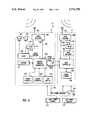
- FIG. 1illustrates a system according to a preferred embodiment of the present invention including a paging system, plurality of radio stations, and plurality of remote receivers each including a low power data receiver combined with an audio receiver.
- FIG. 2is a block diagram of one of the radio stations of FIG. 1 including a multiple-component audio source and a subcarrier generator to produce a combined audio and data transmission.
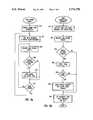
- FIGS. 3A and 3Bare flow charts illustrating operation of the audio source and subcarrier generator, respectively, of FIG. 2.
- FIG. 4is a block diagram of one of the remote receivers of FIG. 1.
- FIG. 5Ais a flow chart illustrating a high power mode of operation for the data receiver portion of a remote receiver of FIG. 1.
- FIG. 5Bis a flow chart illustrating a paging data interrupt routine for the data receiver portion of the remote receiver of FIG. 1.
- a system 10 in accordance with a preferred embodiment of the present inventionwill be illustrated in the context of a paging system 20 coupled to a plurality of FM radio stations 18, individually 18a-18c.
- Radio stations 18each transmit a combined audio and data radio signal 12 to a population of remote receivers 14.
- receivers 14are located in a variety of locations, e.g., home audio system 15 or vehicles 16. While a limited number of radio stations 18 and receivers 14 are illustrated in FIG. 1, it will be understood that the present invention may be implemented with any given number of such radio stations and remote receiving devices.
- Callers 19connect to system 20 and generate paging requests 21 through a public switch telephone network (PSTN) 22.
- PSTNpublic switch telephone network
- paging system 20delivers a stream of paging data 24 to radio stations 18 via PSTN 22 according to a time-division multiplexed protocol.
- Each radio station 18incorporates paging data 24 into a sideband frequency of its signal 12 by use of a subcarrier generator device.
- Radio stations 18transmit the audio portion of signal 12 at a given station frequency in conventional fashion and transmit the sideband or data portion at a given frequency offset relative to the station frequency.
- remote paging devicesactivate at certain brief time slots, monitor a selected sideband signal, and receive a data packet.
- Addressing schemesassociate a given pager with certain time slots and also allow certain pagers to share time slots.
- Pagersseek paging information by selectively tuning to one of a plurality of radio stations and synchronizing relative to a repeating frame of time slots. Each pager targets a given station frequency and time slot for paging message reception, but otherwise remains dormant during virtually all of the repeating time frame.
- the pagersstore and make available for display paging messages addressed thereto.
- each remote receivermust stand ready to tune to a selected frequency during a selected time slot and receive a data packet.
- U.S. Pat. No. 4,713,808shows a paging system including a multi-frequency time-division multiplexed paging system including a clearinghouse and FM radio stations.
- Each FM radio stationprovides in a main audio channel an audio signal and provides in a subcarrier signal paging data directed to a population of remote paging devices.
- the present inventionmay be implemented in a variety of radio signal transmission systems, however, the present invention will be illustrated by reference to paging system 20.
- Each of receivers 14include corresponding receiver decoding circuitry for accessing and decoding the paging system broadcast and protocol.
- Each radio station 18also incorporates into the data portion of its signal 12 information descriptive of the current audio portion presentation, i.e., incorporates digital collateral data, for presentation at receivers 14. While discussed herein generally as textual presentation, it will be understood that digital collateral data may also represent graphic images and may also be converted, e.g. text-to-speech conversion, for audible presentation.
- the term "collateral data"shall refer to a variety of identifying or descriptive information with respect to a given audio presentation, e.g., song title, song classification, producer, artist, advertiser name, radio station identification, and the like.
- the subject matter of the present inventionconcerns coordinated reception and use of the audio portion, e.g. voice, music, and announcement presentation; of the data portion, e.g. textual display of collateral data; and of paging messages, e.g., taken from signals 12 and stored or displayed at receivers 14.
- FIG. 2illustrates generally one of radio stations 18 as coupled to public switch telephone network 22 and providing a combined voice and data radio signal 12.
- a stereo generator 200receives left and right channels of a main audio signal 202 from a multiple-component programmable audio source 204.
- left and right channels of signal 202are combined, subtracted, applied to a pilot generator, and subjected to other known procedures to derive a stereo multiplexed signal 206.
- Exciter 210receives the sum of stereo multiplexed signal 206 and a subcarrier signal 208.
- Excitor 210applies its output 220 to an amplifier 222 driving antenna 224 and to transmit the combined voice and data radio signal 12 to receivers 14.
- a subcarrier generator 214provides subcarrier signal 208 partially from the stream of paging data 24, obtained by way of modem 216 coupled to telephone network 22, and partially from digital collateral data 218 obtained from audio source 204.
- Paging data 24represents the normal flow or stream of paging data obtained from paging system 20 and injected as a subcarrier component of radio signal 12.
- Digital collateral data 218represents identifying or descriptive data with respect to audio signal 202.
- Subcarrier generator 214incorporates the digital collateral data 218 into the stream of paging data 24 according to paging system 20 broadcast protocol. In the illustrated embodiment, paging system 20 broadcasts paging message data packets during particular time slots according to a time-division multiplexed protocol, and digital collateral data 218 replaces unused data packets in the stream of paging data 24.
- a plurality of audio components, or sub-sources, 250drive an audio mixer 252 producing the audio signal 202 as its output.
- Components 250comprise various individual audio sources such as tape machines and CD players storing audio items for programmed presentation by radio station 18.
- a control 254applies control commands 256 and 257 to audio components 250 and audio mixer 252, respectively, according to a prearranged play list 260.
- Play list 260 itemsspecify command information needed to operate a given one of components 250 and further include descriptive or identifying information. Play list 260 thereby dictates operation of control 254 in issuing commands 256 and 257 to components 250 and audio mixer 252, and also serves as a source for the digital collateral data 218.
- FIG. 3Aillustrates control 254 operation with respect to audio signal 202 production.
- FIG. 3is a flow chart illustrating a "play audio" routine executed by control 254 of each radio station 18.
- Control 254first selects a next item from play list 260 in block 300 and then in block 302 starts play of the selected item. The selected item thereby appears in the audio portion of signal 12 for that radio station 18.
- control 254sends corresponding digital collateral data 218 to subcarrier 214.
- control 254sends identifying or descriptive information relative to the audio item just taken from the play list 260 and playing on one of components 250. Programming then loops at decision block 306 until the current audio item completes play. Once complete, processing returns to block 300 where a next audio item is selected and played, and corresponding digital collateral data 218 is sent to subcarrier generator 214.
- FIG. 3Bis a flow chart illustrating operation of the subcarrier generator 214.
- subcarrier generator 214initializes in block 350 a FILL DATA variable with a null value and proceeds to decision block 302 where it determines whether new digital collateral data 218 has arrived from audio source 204. If no new digital collateral data 218 has arrived then processing advances to block 354, but if new digital collateral data 218 has arrived subcarrier generator 214 sets the FILL DATA variable to equal the value of the new digital collateral data 218.
- subcarrier generator 214incorporates the current FILL DATA value into one or more unused data packets of the stream of paging data 24, and thereby fills unused time slots of the paging system 20 protocol with digital collateral data 218 corresponding to the current audio presentation for this radio station 18.
- subcarrier generator 214provides as its output the combined digital collateral data 218, as generated by the radio station 18, and paging data as generated by paging system 20. Processing then returns to decision block 352 to determine whether new digital collateral data 218 has arrived from audio source 204.
- each radio station 218presents a series of programmed audio items in the audio portion of its signal 12 while concurrently presenting in the data or subcarrier portion of its signal 12 combined digital collateral data 218 and paging data 24.
- each radio station 18serves as a paging system 20 transmission facility.
- a given radio station 18need not be part of the paging system 20 transmission facility.
- the radio station 18would include a subcarrier generator, but need not combine paging data with digital collateral data.
- the broadcast 12would then include an audio portion and a data portion including only digital collateral data.
- FIG. 4illustrates in simplified block diagram a receiver 14 as contemplated under the present invention.
- Receivers 14each include an audio portion 15 and a data receiver portion 17.
- Data portion 17is a low power device corresponding generally to a pager under system 20.
- the audio portioncorresponds generally to a conventional FM audio receiver.
- Each of portions 15 and 17are modified to establish interaction therebetween and operation under the present invention as described herein.
- the data portion 17selectively monitors the data portion of one signals 12 as necessary to satisfy the desired paging function according to system 20 protocol. Further, when not seeking paging messages and when sufficient power is available, data portion 17 monitors the subcarrier of a specific signal 12 as indicated by the audio portion 15 of receiver 14, i.e. collects collateral data 218 corresponding to the user-selected radio station 18.
- An audio receiver 400receives, via antenna 402, a signal 12 from one of radio stations 18 as established by a tune signal 408 originating from a general purpose controller 410. Receiver 400 applies the baseband composite signal 412 to a filter 414 to obtain an audio signal 416. Audio signal 416 drives an audio block 420 coupled to a pair of speakers 422 and operating in response to a volume, balance, and tone control signal 424 originating from controller 410.
- Tuner controls block 426includes conventional FM radio control buttons and knobs in implementation of the tune signal 408 and volume, balance, and tone control signal 424.
- Display controls block 428provides user-buttons for manipulation of a textual display at LCD display block 430, e.g., manipulation of paging message and collateral data textual presentation.
- Audio portion 15 of each receiver 14operates generally as a conventional FM radio receiver tunable to a given FM station for presentation of an audio signal at speakers 422. Modification relative to conventional operation includes and interface to the data portion 17 of receiver 14.
- general purpose controller 410provides to data controller 454 a tuned audio frequency 435 representing the station 18 to which audio receiver 400 is currently tuned, i.e., a representation of tune signal 408.
- a data controller 454 of data portion 17provides to general purpose controller 410 decoded data 432 whereby storage and presentation of paging data 24 and digital collateral data 218 is accomplished by the storage and user-interface resources of audio portion 15 of receiver 14. This arrangement avoids duplication of display and storage resources in the receiver 14.
- data portion 17could be provided with its own storage and display resources. Such arrangement would further minimize the interface between data portion 17 and audio portion 17 of receiver 14, and minimize modifications relative to conventional audio receiver design. As will be discussed more fully hereafter, data portion 17 does include a small local storage block 455 for storing selected data packets when general purpose controller 410 is unavailable, i.e., not operating for lack of high power source 470 availability.
- Data receiver 450monitors, via antenna 451, the subcarrier or data portion of a selected station 18 signal 12 according to a tune signal 452 provided by a data controller 454.
- a filter 416couples the data receiver 450 output 418 to a data decoder block 456.
- Decoder block 456reacts to paging system 20 protocol to extract therefrom a sequence of data packets.
- Receiver 14, according to paging system 20 operationactivates only during certain targeted and brief, i.e., 13 millisecond, time slots to receive paging messages. Such time-division multiplexed protocol conserves battery power. As illustrated herein, however, when sufficient power is available, e.g. vehicle 16 ignition power present, controller 454 monitors constantly a sequence of data packets derived from the data portion 418 taken from radio signal 12.
- Controller 454provides selected data packets 432 to controller 410. Controller 454 evaluates received data packets in implementation of a given paging system 20 addressing scheme, i.e., keeping those data packets 432 addressed specifically to a given receiver 14, and also in implementation of the present invention keeping those data packets 432 carrying representation of digital collateral data 218 identifying and describing a current audio presentation in the radio signal 12 to which the audio receiver 400 is currently tuned. Controller 454 determines the current tuning of audio receiver 400 by reference to the tuned audio frequency 435 provided by general purposed controller 410.
- LCD display block 430allows controller 410 to present textually the content of data packets 432 in response to user manipulation of display controls block 428.
- Storage block 431allows controller 410 to save a given number of data packets 432.
- controller 410interacts with blocks 428, 430, and 431 according to an established user-interface to implement selected storage and textual display of paging data 24 addressed to receiver 14 and digital collateral data 218 collected by receiver 14.
- Each receiver 14has two power sources, i.e., a high power source 470 and a low power source 472.
- High power source 470e.g., a vehicle 16 power system
- Low power source 472e.g., a small battery such as a watch battery
- Switch 474receives energy from high power source 470 and from low power source 472.
- Switch 474applies to data portion 17 the high power source 470 when available and otherwise applies low power source 472.
- a high power available signal 476drives switch 474 to apply the selected power source to data portion 17. Further, data portion 17 monitors the high power available signal 476 to determine the current power mode.
- data portion 17when operating from low power source 472, data portion 17 operates according to its normal paging function, i.e., activating at certain targeted time slots and monitoring certain stations 18 to receive data packets bearing paging messages addressed to that particular paging receiver.
- data portion 17constantly collects data packets from a radio station 18 sideband frequency corresponding to the radio station 18 to which audio receiver 400 is currently tuned. Data portion 17 thereby reacts to availability of power and performs the additional function of digital collateral data 418 reception without excessively diminishing the low power source 472 and without interrupting normal paging message reception functions.
- receiver 14could be incorporated into an AC-powered device, e.g., home audio system 15.
- high power source 470is only be available when the device is switched-on or plugged into a wall receptacle.
- low power source 472is always available for operation of data portion 17 to reliably execute the higher priority paging function.
- FIGS. 5A and 5Bare flow charts illustrating programming for data controller 454.
- FIG. 5Ashows a high power mode of operation for controller 454 executed when sufficient power is available to allow constant monitoring of digital collateral data 218.
- FIG. 5Bshows operation relative to receiving of paging data 24, in particular a seek paging data interrupt routine executed with reference to the repeating time frame of system 20 protocol to activate and monitor a selected signal 12 sideband transmission during a targeted time slot.
- the interrupt procedure of FIG. 5Boccurs regardless of high power source 470 availability, there being low power source 472 always available for operation of data portion 17.
- processing of FIG. 5Aoccurs with the interrupt routine of FIG. 5B enabled to allow collection of paging data 24 as a higher priority function relative to collection of digital collateral data 218.
- controller 454reacts to the availability of high power source 470 by first enabling in block 500 the interrupt processing, i.e. paging message targeting and collection, of FIG. 5B. Continuing to block 502, controller 454 references its tuned audio frequency 435 input and tunes data receiver 450 to match the current tuning of audio receiver 400. In block 504 controller 454 receives a data packet according to paging system 20 protocol. Processing then advances to decision block 506 where controller 454 interrogates the content of the received data packet to identify representation of the digital collateral data 218 therein. As may be appreciated, data packets carrying digital collateral 218 include an identification field differentiating digital collateral data 218 from paging messages.
- controller 454sends the just-received digital collateral data 218 to controller 410 as decoded data 432 for textual presentation at display block 430. Otherwise, processing advances to decision block 512. In decision block 512, controller 454 determines if the user has switched to a different station 18 by again referencing its tuned audio frequency 435 input. If audio receiver 400 has been tuned by the user to a new frequency then processing returns to tuning block 502, but otherwise returns to receiving block 504.
- FIG. 5Billustrates the paging data interrupt routine executed by data portion 17 of receiver 14 regardless of availability of high power source 470.
- processingbegins in block 550 where controller 454 activates data receiver 450 and data decoder 456 and also tunes data receiver 450 by application of tune signal 452.
- activationi.e., initiation of the FIG. 5B interrupt process, corresponds to a selected or targeted time slot of system 20 broadcast protocol associated with this particular receiver 14.
- Tuning in block 550corresponds to a selected one of radio stations 18 targeted for collecting specific paging data.
- System 20broadcasts information redundantly on radio stations 18, with a given time offset between station 18 time frames.
- a pagerswitches frequencies, i.e., tunes to a different station 18 and synchronizes to its offset time frame.
- each pagerseeks paging data by selecting a particular radio station 18 and time slot relative to that radio station 18 time frame.
- controller 454receives and decodes a data packet.
- controller 454compares its address with an address field of the decoded packet, i.e., determines whether the data packet is addressed to this particular receiver. If the address fails to match, processing branches from decision block 554 to block 562 where controller 454 sets its interrupt for a next targeted time slot, i.e., a next occurrence for the paging data interrupt routine of FIG. 5B. Processing of FIG. 5B then exits from block 562.
- processingbranches from decision block 554 to block 556 where controller 454 stores the decoded data packet in local storage block 455.
- local storage block 455is of sufficient size to hold a desired number of decoded data packets, i.e., capable of storing a given number of paging messages.
- controller 454determines availability of high power source 470, i.e., references high power command 476. If high power source 470 is currently being used, then processing branches to block 560 where controller 454 sends stored data packets to general purpose controller 410 and clears from local storage block 455 the stored data packets.
- Processingthen advances from block 560 to block 562 and continues as described above. If high power source 470 is not being used, i.e., general purpose controller 410 not available to accept decoded data packets, then processing branches from decision block 558 directly to block 562.
- high power source 470i.e., general purpose controller 410 not available to accept decoded data packets, then processing branches from decision block 558 directly to block 562.
- the data portionmay be incorporated into existing device design by appropriate interface coupling.
- the data portionmay be incorporated into vehicle radios, home audio systems, personal computers, and generally into any existing product form as a mechanism to manage both paging functions and also digital collateral data.
- the deviceadvantageously collects all digital collateral information on a given radio station.
- a second low power sourceremains constantly available to serve the higher priority paging functions. In this manner, a receiver 14 presently unused remains available to collect paging data.
Landscapes
- Engineering & Computer Science (AREA)
- Signal Processing (AREA)
- Computer Networks & Wireless Communication (AREA)
- Physics & Mathematics (AREA)
- Electromagnetism (AREA)
- General Physics & Mathematics (AREA)
- Mobile Radio Communication Systems (AREA)
- Circuits Of Receivers In General (AREA)
Abstract
Description
Claims (8)
Priority Applications (6)
| Application Number | Priority Date | Filing Date | Title |
|---|---|---|---|
| US08/502,807US5774798A (en) | 1995-07-14 | 1995-07-14 | Low power data receiver combined with audio receiver |
| AU63460/96AAU6346096A (en) | 1995-07-14 | 1996-07-02 | Low power data receiver combined with audio receiver |
| JP50670497AJP3917657B2 (en) | 1995-07-14 | 1996-07-02 | Low power data receiver combined with audio receiver |
| PCT/US1996/011327WO1997004531A1 (en) | 1995-07-14 | 1996-07-02 | Low power data receiver combined with audio receiver |
| EP96922660AEP0842565A4 (en) | 1995-07-14 | 1996-07-02 | Low power data receiver combined with audio receiver |
| CA002221742ACA2221742A1 (en) | 1995-07-14 | 1996-07-02 | Low power data receiver combined with audio receiver |
Applications Claiming Priority (1)
| Application Number | Priority Date | Filing Date | Title |
|---|---|---|---|
| US08/502,807US5774798A (en) | 1995-07-14 | 1995-07-14 | Low power data receiver combined with audio receiver |
Publications (1)
| Publication Number | Publication Date |
|---|---|
| US5774798Atrue US5774798A (en) | 1998-06-30 |
Family
ID=23999507
Family Applications (1)
| Application Number | Title | Priority Date | Filing Date |
|---|---|---|---|
| US08/502,807Expired - LifetimeUS5774798A (en) | 1995-07-14 | 1995-07-14 | Low power data receiver combined with audio receiver |
Country Status (6)
| Country | Link |
|---|---|
| US (1) | US5774798A (en) |
| EP (1) | EP0842565A4 (en) |
| JP (1) | JP3917657B2 (en) |
| AU (1) | AU6346096A (en) |
| CA (1) | CA2221742A1 (en) |
| WO (1) | WO1997004531A1 (en) |
Cited By (20)
| Publication number | Priority date | Publication date | Assignee | Title |
|---|---|---|---|---|
| US6041087A (en)* | 1996-09-13 | 2000-03-21 | Sumitomo Wiring Systems, Ltd. | Information receiving system and an information receiving method using such a system |
| US6140937A (en)* | 1997-03-17 | 2000-10-31 | Sony Corporation | Modular pager unit removably incorporated with a personal electronic device |
| US6163683A (en)* | 1999-02-24 | 2000-12-19 | International Business Machines Corporation | Broadcast data radio system and receiver apparatus therefor |
| US6230134B1 (en)* | 1996-06-25 | 2001-05-08 | Robert Bosch Gmbh | Process for separating and characterizing spoken announcements in a radio transmission |
| US6272191B1 (en)* | 1997-09-09 | 2001-08-07 | Sumitomo Wiring Systems, Ltd. | Information receiving system and an information receiving method using such a system |
| US20020099882A1 (en)* | 2001-01-25 | 2002-07-25 | Pioneer Corporation | Switchover device and information recording/reproducing apparatus having the switchover device |
| US6751454B2 (en) | 2001-05-29 | 2004-06-15 | Leap Wireless International, Inc. | System and method for sampling audio recordings on a wireless communication device |
| US6757913B2 (en)* | 1996-07-15 | 2004-06-29 | Gregory D. Knox | Wireless music and data transceiver system |
| US6904270B1 (en)* | 1999-02-04 | 2005-06-07 | Hark C. Chan | Radio receiver for processing digital and analog audio signals |
| US20060250282A1 (en)* | 2005-05-03 | 2006-11-09 | Charles Evans | Systems for and methods of remote host-based media presentation |
| US20070169163A1 (en)* | 1997-11-05 | 2007-07-19 | Sony Corporation | Information Distributing System, Information Processing Terminal Device, Information Center, And Information Distributing Method |
| US7369824B1 (en) | 1999-02-04 | 2008-05-06 | Chan Hark C | Receiver storage system for audio program |
| US20080162300A1 (en)* | 2003-09-26 | 2008-07-03 | Ewald Stephen A | System and Method for Purchasing Linked with Broadcast Media |
| US20090180579A1 (en)* | 2008-01-04 | 2009-07-16 | Ellis Michael D | Digital radio systems and methods |
| US20090258619A1 (en)* | 2008-04-09 | 2009-10-15 | Ellis Michael D | Radio device with virtually infinite simultaneous inputs |
| US7783014B1 (en) | 1999-03-26 | 2010-08-24 | Chan Hark C | Decryption and decompression based audio system |
| CN102497214A (en)* | 2011-12-13 | 2012-06-13 | 方正国际软件有限公司 | Wireless multi-channel explanation device and multi-channel explanation method thereof |
| US8788075B2 (en) | 2001-02-20 | 2014-07-22 | 3D Radio, Llc | Multiple radio signal processing and storing method and apparatus |
| US9189954B2 (en) | 2008-04-09 | 2015-11-17 | 3D Radio, Llc | Alternate user interfaces for multi tuner radio device |
| US9197269B2 (en) | 2008-01-04 | 2015-11-24 | 3D Radio, Llc | Multi-tuner radio systems and methods |
Families Citing this family (1)
| Publication number | Priority date | Publication date | Assignee | Title |
|---|---|---|---|---|
| JP6329000B2 (en)* | 2014-05-27 | 2018-05-23 | Necプラットフォームズ株式会社 | Wireless communication system, communication control apparatus, communication method, control method, and program |
Citations (7)
| Publication number | Priority date | Publication date | Assignee | Title |
|---|---|---|---|---|
| US4379947A (en)* | 1979-02-02 | 1983-04-12 | Teleprompter Corporation | System for transmitting data simultaneously with audio |
| US5146612A (en)* | 1989-04-17 | 1992-09-08 | Spingarn James L | Technique for using a subcarrier frequency of a radio station to transmit, receive and display a message together with audio reproduction of the radio program |
| US5170487A (en)* | 1989-01-19 | 1992-12-08 | Seiko Corp. | Paging system with multiple frequencies and multiple protocols |
| US5394562A (en)* | 1992-08-25 | 1995-02-28 | Blaupunkt-Werke Gmbh | Power supply circuit for a two-mode vehicular radio receiver |
| US5408686A (en)* | 1991-02-19 | 1995-04-18 | Mankovitz; Roy J. | Apparatus and methods for music and lyrics broadcasting |
| US5535428A (en)* | 1994-07-28 | 1996-07-09 | Motorola, Inc. | Method and apparatus for selectively retaining messages received by a radio receiver based upon message content |
| US5572194A (en)* | 1993-09-10 | 1996-11-05 | Sony Corporation | Broadcast receiver and signal reproduction apparatus controlled using RDS data |
- 1995
- 1995-07-14USUS08/502,807patent/US5774798A/ennot_activeExpired - Lifetime
- 1996
- 1996-07-02CACA002221742Apatent/CA2221742A1/ennot_activeAbandoned
- 1996-07-02WOPCT/US1996/011327patent/WO1997004531A1/ennot_activeApplication Discontinuation
- 1996-07-02JPJP50670497Apatent/JP3917657B2/ennot_activeExpired - Lifetime
- 1996-07-02AUAU63460/96Apatent/AU6346096A/ennot_activeAbandoned
- 1996-07-02EPEP96922660Apatent/EP0842565A4/ennot_activeWithdrawn
Patent Citations (7)
| Publication number | Priority date | Publication date | Assignee | Title |
|---|---|---|---|---|
| US4379947A (en)* | 1979-02-02 | 1983-04-12 | Teleprompter Corporation | System for transmitting data simultaneously with audio |
| US5170487A (en)* | 1989-01-19 | 1992-12-08 | Seiko Corp. | Paging system with multiple frequencies and multiple protocols |
| US5146612A (en)* | 1989-04-17 | 1992-09-08 | Spingarn James L | Technique for using a subcarrier frequency of a radio station to transmit, receive and display a message together with audio reproduction of the radio program |
| US5408686A (en)* | 1991-02-19 | 1995-04-18 | Mankovitz; Roy J. | Apparatus and methods for music and lyrics broadcasting |
| US5394562A (en)* | 1992-08-25 | 1995-02-28 | Blaupunkt-Werke Gmbh | Power supply circuit for a two-mode vehicular radio receiver |
| US5572194A (en)* | 1993-09-10 | 1996-11-05 | Sony Corporation | Broadcast receiver and signal reproduction apparatus controlled using RDS data |
| US5535428A (en)* | 1994-07-28 | 1996-07-09 | Motorola, Inc. | Method and apparatus for selectively retaining messages received by a radio receiver based upon message content |
Cited By (45)
| Publication number | Priority date | Publication date | Assignee | Title |
|---|---|---|---|---|
| US6230134B1 (en)* | 1996-06-25 | 2001-05-08 | Robert Bosch Gmbh | Process for separating and characterizing spoken announcements in a radio transmission |
| US6757913B2 (en)* | 1996-07-15 | 2004-06-29 | Gregory D. Knox | Wireless music and data transceiver system |
| US6041087A (en)* | 1996-09-13 | 2000-03-21 | Sumitomo Wiring Systems, Ltd. | Information receiving system and an information receiving method using such a system |
| US6140937A (en)* | 1997-03-17 | 2000-10-31 | Sony Corporation | Modular pager unit removably incorporated with a personal electronic device |
| US6272191B1 (en)* | 1997-09-09 | 2001-08-07 | Sumitomo Wiring Systems, Ltd. | Information receiving system and an information receiving method using such a system |
| US20070169163A1 (en)* | 1997-11-05 | 2007-07-19 | Sony Corporation | Information Distributing System, Information Processing Terminal Device, Information Center, And Information Distributing Method |
| US9454949B2 (en) | 1997-11-05 | 2016-09-27 | Sony Corporation | Information distributing system, information processing terminal device, information center, and information distributing method |
| US8589506B2 (en) | 1997-11-05 | 2013-11-19 | Sony Corporation | Information distributing system, information processing terminal device, information center, and information distributing method |
| US8024649B1 (en)* | 1997-11-05 | 2011-09-20 | Sony Corporation | Information distributing system, information processing terminal device, information center, and information distributing method |
| US8010068B1 (en) | 1999-02-04 | 2011-08-30 | Chan Hark C | Transmission and receiver system operating on different frequency bands |
| US8103231B1 (en) | 1999-02-04 | 2012-01-24 | Chan Hark C | Transmission and receiver system operating on different frequency bands |
| US6904270B1 (en)* | 1999-02-04 | 2005-06-07 | Hark C. Chan | Radio receiver for processing digital and analog audio signals |
| US7369824B1 (en) | 1999-02-04 | 2008-05-06 | Chan Hark C | Receiver storage system for audio program |
| US9608744B1 (en) | 1999-02-04 | 2017-03-28 | Hark C Chan | Receiver system for audio information |
| US7403753B1 (en) | 1999-02-04 | 2008-07-22 | Chan Hark C | Receiving system operating on multiple audio programs |
| US9026072B1 (en) | 1999-02-04 | 2015-05-05 | Hark C Chan | Transmission and receiver system operating on different frequency bands |
| US7778614B1 (en) | 1999-02-04 | 2010-08-17 | Chan Hark C | Receiver storage system for audio program |
| USRE45362E1 (en) | 1999-02-04 | 2015-02-03 | Hark C Chan | Transmission and receiver system operating on multiple audio programs |
| US8489049B1 (en) | 1999-02-04 | 2013-07-16 | Hark C Chan | Transmission and receiver system operating on different frequency bands |
| US7856217B1 (en) | 1999-02-04 | 2010-12-21 | Chan Hark C | Transmission and receiver system operating on multiple audio programs |
| US6163683A (en)* | 1999-02-24 | 2000-12-19 | International Business Machines Corporation | Broadcast data radio system and receiver apparatus therefor |
| US7783014B1 (en) | 1999-03-26 | 2010-08-24 | Chan Hark C | Decryption and decompression based audio system |
| US6845413B2 (en)* | 2001-01-25 | 2005-01-18 | Pioneer Corporation | Switchover device and information recording/reproducing apparatus having the switchover device |
| US20020099882A1 (en)* | 2001-01-25 | 2002-07-25 | Pioneer Corporation | Switchover device and information recording/reproducing apparatus having the switchover device |
| US9419665B2 (en) | 2001-02-20 | 2016-08-16 | 3D Radio, Llc | Alternate user interfaces for multi tuner radio device |
| US11108482B2 (en) | 2001-02-20 | 2021-08-31 | 3D Radio, Llc | Enhanced radio systems and methods |
| US11075706B2 (en) | 2001-02-20 | 2021-07-27 | 3D Radio Llc | Enhanced radio systems and methods |
| US10958773B2 (en) | 2001-02-20 | 2021-03-23 | 3D Radio, Llc | Entertainment systems and methods |
| US10721345B2 (en) | 2001-02-20 | 2020-07-21 | 3D Radio, Llc | Entertainment systems and methods |
| US8788075B2 (en) | 2001-02-20 | 2014-07-22 | 3D Radio, Llc | Multiple radio signal processing and storing method and apparatus |
| US10447835B2 (en) | 2001-02-20 | 2019-10-15 | 3D Radio, Llc | Entertainment systems and methods |
| US6751454B2 (en) | 2001-05-29 | 2004-06-15 | Leap Wireless International, Inc. | System and method for sampling audio recordings on a wireless communication device |
| US20080162300A1 (en)* | 2003-09-26 | 2008-07-03 | Ewald Stephen A | System and Method for Purchasing Linked with Broadcast Media |
| US7801478B2 (en)* | 2005-05-03 | 2010-09-21 | Marvell International Technology Ltd. | Systems for and methods of remote host-based media presentation |
| US20060250282A1 (en)* | 2005-05-03 | 2006-11-09 | Charles Evans | Systems for and methods of remote host-based media presentation |
| US8244172B2 (en) | 2005-05-03 | 2012-08-14 | Marvell International Technology Ltd. | Remote host-based media presentation |
| US20100332983A1 (en)* | 2005-05-03 | 2010-12-30 | Marvell International Technology Ltd. | Remote host-based media presentation |
| US9197269B2 (en) | 2008-01-04 | 2015-11-24 | 3D Radio, Llc | Multi-tuner radio systems and methods |
| US20090180579A1 (en)* | 2008-01-04 | 2009-07-16 | Ellis Michael D | Digital radio systems and methods |
| US8868023B2 (en)* | 2008-01-04 | 2014-10-21 | 3D Radio Llc | Digital radio systems and methods |
| US20090258619A1 (en)* | 2008-04-09 | 2009-10-15 | Ellis Michael D | Radio device with virtually infinite simultaneous inputs |
| US9189954B2 (en) | 2008-04-09 | 2015-11-17 | 3D Radio, Llc | Alternate user interfaces for multi tuner radio device |
| US8909128B2 (en) | 2008-04-09 | 2014-12-09 | 3D Radio Llc | Radio device with virtually infinite simultaneous inputs |
| CN102497214B (en)* | 2011-12-13 | 2014-06-25 | 方正国际软件有限公司 | Wireless multi-channel explanation device and multi-channel explanation method thereof |
| CN102497214A (en)* | 2011-12-13 | 2012-06-13 | 方正国际软件有限公司 | Wireless multi-channel explanation device and multi-channel explanation method thereof |
Also Published As
| Publication number | Publication date |
|---|---|
| AU6346096A (en) | 1997-02-18 |
| JPH11509393A (en) | 1999-08-17 |
| EP0842565A1 (en) | 1998-05-20 |
| CA2221742A1 (en) | 1997-02-06 |
| JP3917657B2 (en) | 2007-05-23 |
| WO1997004531A1 (en) | 1997-02-06 |
| EP0842565A4 (en) | 2000-09-13 |
Similar Documents
| Publication | Publication Date | Title |
|---|---|---|
| US5774798A (en) | Low power data receiver combined with audio receiver | |
| US5408686A (en) | Apparatus and methods for music and lyrics broadcasting | |
| US5751806A (en) | Audio information dissemination using various transmission modes | |
| US6330334B1 (en) | Method and system for information dissemination using television signals | |
| US5239540A (en) | Method and apparatus for transmitting, receiving and communicating digital data signals with corresponding program data signals which describe the digital data signals | |
| US9886503B2 (en) | Method and apparatus for multiplexing audio program channels from one or more received broadcast streams to provide a playlist style listening experience to users | |
| USRE37131E1 (en) | Apparatus and methods for music and lyrics broadcasting | |
| US20150004900A1 (en) | Method and apparatus for wireless digital radio | |
| US7437124B2 (en) | Satellite radio receiver that displays information regarding one or more channels that are not currently being listened to | |
| US20120263305A1 (en) | Method and apparatus for multiplexing audio program channels from one or more received broadcast streams to provide a playlist style listening experience to users | |
| MXPA05003092A (en) | Method and apparatus for navigating, previewing and selecting broadband channels via a receiving user interface. | |
| EP0673568A1 (en) | Apparatus and methods for music and lyrics broadcasting | |
| JPH10507609A (en) | Method and apparatus for displaying a broadcast station name and a program type transmitted on a digital data telegram of a broadcast station on a broadcast receiver display | |
| WO1996037965A1 (en) | Record identification technique | |
| JPH08265199A (en) | Receiver for broadcasting to synchronize required broadcasting station and its method | |
| JPH11505683A (en) | Dual channel FM receiver with on-demand information service | |
| JPH10200431A (en) | Multiplex broadcast keyword retrieval system | |
| EP0800728A1 (en) | Transmitting and displaying on a receiver information describing broadcast programs | |
| JPH0983395A (en) | Multiplex broadcasting receiver | |
| GB2410633A (en) | Broadcast receiver with user audio interface | |
| JPS5925430A (en) | Automatic selective receiving system of broadcast | |
| JP2000059244A (en) | Dab receiver and its method |
Legal Events
| Date | Code | Title | Description |
|---|---|---|---|
| AS | Assignment | Owner name:SEIKO COMMIUNICATION SYSTEMS, INC., OREGON Free format text:ASSIGNMENT OF ASSIGNORS INTEREST;ASSIGNOR:GASKILL, GAROLD B.;REEL/FRAME:007584/0758 Effective date:19950711 | |
| STCF | Information on status: patent grant | Free format text:PATENTED CASE | |
| FPAY | Fee payment | Year of fee payment:4 | |
| AS | Assignment | Owner name:SEIKO INSTRUMENTS, INC., JAPAN Free format text:ASSIGNMENT OF ASSIGNORS INTEREST;ASSIGNOR:SEIKO COMMUNICATION SYSTEMS, INC.;REEL/FRAME:015503/0367 Effective date:20041228 | |
| FPAY | Fee payment | Year of fee payment:8 | |
| AS | Assignment | Owner name:SEIKO INSTRUMENTS INC., JAPAN Free format text:ASSIGNMENT OF ASSIGNORS INTEREST;ASSIGNOR:SEIKO COMMUNICATIONS SYSTEMS INC.;REEL/FRAME:020866/0860 Effective date:20080418 | |
| FEPP | Fee payment procedure | Free format text:PAYER NUMBER DE-ASSIGNED (ORIGINAL EVENT CODE: RMPN); ENTITY STATUS OF PATENT OWNER: LARGE ENTITY Free format text:PAYOR NUMBER ASSIGNED (ORIGINAL EVENT CODE: ASPN); ENTITY STATUS OF PATENT OWNER: LARGE ENTITY | |
| AS | Assignment | Owner name:PROTOCOL-IP.COM, L.L.C., DELAWARE Free format text:ASSIGNMENT OF ASSIGNORS INTEREST;ASSIGNOR:SEIKO INSTRUMENTS INC.;REEL/FRAME:022024/0063 Effective date:20080201 | |
| FPAY | Fee payment | Year of fee payment:12 |