US5774618A - Compact closure for optical fiber cable - Google Patents
Compact closure for optical fiber cableDownload PDFInfo
- Publication number
- US5774618A US5774618AUS08/773,811US77381196AUS5774618AUS 5774618 AUS5774618 AUS 5774618AUS 77381196 AUS77381196 AUS 77381196AUS 5774618 AUS5774618 AUS 5774618A
- Authority
- US
- United States
- Prior art keywords
- closure
- end plate
- backbone
- grommet
- cable
- Prior art date
- Legal status (The legal status is an assumption and is not a legal conclusion. Google has not performed a legal analysis and makes no representation as to the accuracy of the status listed.)
- Expired - Lifetime
Links
- 239000013307optical fiberSubstances0.000titleclaimsabstractdescription28
- 238000007789sealingMethods0.000claimsabstractdescription22
- XLYOFNOQVPJJNP-UHFFFAOYSA-NwaterSubstancesOXLYOFNOQVPJJNP-UHFFFAOYSA-N0.000claimsabstractdescription10
- 230000000903blocking effectEffects0.000claims4
- 230000013011matingEffects0.000claims1
- 239000000835fiberSubstances0.000abstractdescription23
- 230000000694effectsEffects0.000abstractdescription2
- 239000004020conductorSubstances0.000description7
- 230000006870functionEffects0.000description6
- 239000008393encapsulating agentSubstances0.000description5
- 238000012423maintenanceMethods0.000description5
- 239000000463materialSubstances0.000description5
- 239000003365glass fiberSubstances0.000description4
- 239000002184metalSubstances0.000description4
- 238000000034methodMethods0.000description4
- 238000005452bendingMethods0.000description3
- 230000005540biological transmissionEffects0.000description3
- 239000004033plasticSubstances0.000description3
- 238000012360testing methodMethods0.000description3
- VYPSYNLAJGMNEJ-UHFFFAOYSA-NSilicium dioxideChemical compoundO=[Si]=OVYPSYNLAJGMNEJ-UHFFFAOYSA-N0.000description2
- 230000006978adaptationEffects0.000description2
- 238000004891communicationMethods0.000description2
- 238000010276constructionMethods0.000description2
- 239000013536elastomeric materialSubstances0.000description2
- 239000011521glassSubstances0.000description2
- 238000012986modificationMethods0.000description2
- 230000004048modificationEffects0.000description2
- 229910000831SteelInorganic materials0.000description1
- 230000004308accommodationEffects0.000description1
- 230000001154acute effectEffects0.000description1
- 230000002411adverseEffects0.000description1
- 238000004873anchoringMethods0.000description1
- 239000011230binding agentSubstances0.000description1
- 230000015572biosynthetic processEffects0.000description1
- 239000011248coating agentSubstances0.000description1
- 238000000576coating methodMethods0.000description1
- 239000011436cobSubstances0.000description1
- 230000001010compromised effectEffects0.000description1
- 238000013461designMethods0.000description1
- 238000006073displacement reactionMethods0.000description1
- 230000007613environmental effectEffects0.000description1
- 230000001771impaired effectEffects0.000description1
- 238000003780insertionMethods0.000description1
- 230000037431insertionEffects0.000description1
- 238000009434installationMethods0.000description1
- 238000002955isolationMethods0.000description1
- 230000008569processEffects0.000description1
- 230000008707rearrangementEffects0.000description1
- 230000008439repair processEffects0.000description1
- 239000012858resilient materialSubstances0.000description1
- 230000000284resting effectEffects0.000description1
- 239000000377silicon dioxideSubstances0.000description1
- 239000010959steelSubstances0.000description1
- 239000000725suspensionSubstances0.000description1
Images


Classifications
- G—PHYSICS
- G02—OPTICS
- G02B—OPTICAL ELEMENTS, SYSTEMS OR APPARATUS
- G02B6/00—Light guides; Structural details of arrangements comprising light guides and other optical elements, e.g. couplings
- G02B6/44—Mechanical structures for providing tensile strength and external protection for fibres, e.g. optical transmission cables
- G02B6/4439—Auxiliary devices
- G02B6/444—Systems or boxes with surplus lengths
- G02B6/4441—Boxes
- G02B6/4442—Cap coupling boxes
- G—PHYSICS
- G02—OPTICS
- G02B—OPTICAL ELEMENTS, SYSTEMS OR APPARATUS
- G02B6/00—Light guides; Structural details of arrangements comprising light guides and other optical elements, e.g. couplings
- G02B6/44—Mechanical structures for providing tensile strength and external protection for fibres, e.g. optical transmission cables
- G02B6/4439—Auxiliary devices
- G02B6/444—Systems or boxes with surplus lengths
- G02B6/4453—Cassettes
- G02B6/4454—Cassettes with splices
Definitions
- This inventionrelates to a space saving optical fiber closure, and more particularly, to a closure for optical fiber cables which has increased storage capacity, a high level of environmental protection and of water-tight integrity, and which has improved convenience in installation and use and low cost.
- An optical fiber cablemay comprise a plurality of glass fibers, each of which is protected by at least one layer of coating material.
- the fibersmay be assembled into units in which they are held together by binder ribbons or within tubes to provide a core.
- Another optical fiber cable coreincludes a ribbon type fiber arrangement in which a plurality, such as, for example, twelve fibers, are arranged side-by-side in a ribbon configuration. A plurality of such ribbons may be stacked to obtain a high fiber count cable.
- the coreis generally enclosed by a plastic tube and a plastic jacket. Ribbon type cable which contains a relatively large number of optical fibers is well suited for fiber-to-the-customer or fiber-in-the loop use.
- optical fibersincluding their small size, inherent brittleness, and relative fragility forecloses the use of splicing techniques common for metallic conductors, including the orientation of the fibers within the available splice closure space, where too sharp bends, for example, are anathema.
- Transmission capabilitiescan be impaired by bending an optical fiber beyond an allowable bending radius, the point at which light is no longer completely contained within the fiber.
- the expected life of the fibersis reduced if they are bent more sharply than allowed by the minimum bending radius.
- the radius to which an optical fiber can be bent without affecting orderly transmissionis substantially greater than the radius at which the optical fiber will break.
- optical fibersnormally do not possess this potential strength because of microscopic surface fractures, most often incurred in manipulation of the fiber, which are vulnerable to stress and spread, causing the fiber to break easily.
- an optical fiber cabledoes not lend itself to the splicing techniques of metallic conductors.
- the individual glass fiberscannot be twisted, tied, wrapped, and jammed into a splice closure in anything like the manner of wire-like or metallic conductors.
- These small diameter glass fiberscannot be crimped or sharply bent, and, inasmuch as glass fibers have memory, their tendency to return to straight line orientation makes placement within a splice closure somewhat difficult.
- the interconnection of optical fibersis a precision operation which is difficult to perform in the field, such as in a manhole or at pole-suspension elevation.
- the closureshould fulfill all of the aforementioned desiderata while at the same time being of relatively small size and relatively inexpensive.
- the cables extending into or out of the closurebe held tightly to prevent any undesired movement of portions of the cable within the closure. Such movement will also cause movement of the fibers which, in turn, can adversely effect the transmission characteristics of the fibers and place mechanical stresses thereon.
- the cables entering the closurepass through flexible grommets which serve to provide, among other things, sealing of the interior of the closure from the ambient environment. If movement, usually longitudinal, of the cables occurs, the seal between the grommet and the cable can be broken.
- a metal member extending from an inner plate of the closure to an outer end plate and annular worm gear clamps about the cable and the metal memberhave been used to secure the cable to the metal member.
- Displacement of the grommetscan be caused by air pressure within the closure which is used to check the integrity of the seals, or by external forces such as water pressure or ice formation tending to push the grommets inwardly.
- Each closureshould be capable of being used with a range of cable sizes.
- metal cable gripping hardwarehad to be bent, in the field, to accommodate the differing cable sizes.
- the cable sheathswhich can be and often are metallic, be electrically connected together to provide grounding for the sheaths.
- closures for containing splicescomprise a housing, preferably cylindrical, having a closed end, and an open end onto which an end plate is mounted.
- the end plate assemblyhas at least one opening therethrough, a sealing device, i.e., a grommet, disposed in the opening which includes a passageway for a cable to pass therethrough, and a cable sheath gripping assembly disposed within or adjacent to the end plate assembly.
- a sealing devicei.e., a grommet
- An example of such a housingis shown in U.S. Pat. No. 5,097,529 of Cobb et al., and an example of a cable gripping assembly is shown in U.S. Pat. No. 5,280,556 of Jones.
- the present inventionis an optical fiber splice closure which overcomes many of the problems of the prior art while at the same time being of relatively simple compact construction for easy assembly and use, especially in the field.
- the closure of the inventioncomprises a hollow cylindrical cover member having a closed end and an open end, a single piece end plate for the open end and a support means for supporting a splice tray within the closure.
- the end platehas first and second bores therein for containing first and second grommets of resilient elastomeric material, and each grommet has first and second openings therein for receiving the end portions of two optical fiber cables.
- a grommet retainer memberis mounted on the external face of the end plate for retaining the grommets in position within their respective bores.
- the end platehas a circumferential channel therein containing an O-ring sealing member which bears against the periphery of the open end of the cover, and is clamped to the cover by means of over-center clamps of the type shown in the aforementioned Cobb et al. patent.
- a support or backbone memberis located on the interior face of the end plate, either integral therewith or mounted by means of an axially extending double end threaded stud which extends through the end plate and the grommet retaining member to a tightening knob with appropriate sealing means such as an O-ring in the opening in the end plate through which the stud passes.
- the backbone membercomprises a face plate which bears against the inner face of the end plate and which has laterally protruding flanges thereon which bear against the grommets and function as interior stops for them.
- the flanges and the grommet retaining memberwhich also bears against the grommets, prevent any movement of the grommets longitudinally which might break the seals such as would normally occur when tension or pulling forces on the cable occurs, or when there is internal air pressure, or when exterior water or ice pressure exteriorly of the closure would normally force the grommets inwardly, thereby breaking their seal.
- Extending from the rear of the face plate of the backbone memberis a platform upon which are arrayed a plurality of tubular members or elongated bosses designed to receive threaded bolts or screws which extend through the platform, and the interior or distal edge of the platform has an array of threaded bosses extending across it.
- a metallic cantilevered cable sheath grip member having a square U-shapeis mounted to the tubular members by means of a plurality of bolts extending through the base of the U-shape.
- the cantilevered arms of the sheath gripare adapted to grip the cables extending into the closure in conjunction with suitable bonding clamps, and, being cantilevered, they have sufficient flexibility to accommodate cables of various sizes without forcing movement of the cables themselves, which might tend to break the grommet seal.
- the sheath gripinsures that both cables sheaths, where metallic, are at the same potential when the sheath grip is clamped to the cables.
- a distribution organizermounted to the rear of the platform of the backbone by means of bolts threaded into the bosses arrayed along the edge thereof is a distribution organizer to which is mounted, in turn, a splice tray. Also mounted to the undersides of the distribution organizer is a central strength member anchor means for use when the cables have central strength members, such as loose tube cables. Anchoring of the central strength members increases the resistance of the assembly to external forces such as tensile forces on the cable.
- the rear end, i.e., the end remote from the backbone, of the distribution organizeris supported by a support member which snaps onto the end of the distribution organizer and which has a contoured shape for resting against the curved inner wall of the closure.
- the backbone member as describedfunctions as a locus for all of the parts of the closure relating to its function,. Thus, it helps maintain the grommets in fixed position, it supports the means for gripping and bonding the cable sheath, it supports the distribution organizer and splice tray, and it provides a support for an anchor for cable central strength members.
- the closed end of the closureis provided with a flat projecting mounting lug, and the grommet retainer is likewise provided with a similar lug.
- these lugsare aligned by means of a lug on the cover rim and a slot in the end plate, and provide mounting means for support brackets for mounting the closure in fixed position.
- FIG. 1is an exploded perspective view of the cable closure of the present invention
- FIGS. 2A and 2Bare interior and exterior perspective views, respectively, of the closure of FIG. 1;
- FIG. 3Ais a plan view of the interior assembly of the, closure of FIG. 1;
- FIG. 3Bis an elevation view of the closure end of the closure of FIG. 1;
- FIG. 3Cis a cross-sectional view taken along the line I--I of FIG. 3A;
- FIGS. 4A and 4Bare perspective views of the front and rear, respectively, of the grommet retainer member
- FIG. 5Ais an elevation view of the interior side of the end plate of the closure of FIG. 1;
- FIG. 5Bis a side elevation view of the end plate of FIG. 5A;
- FIG. 5Cis an elevation view of the exterior side of the end plate
- FIG. 6Ais a plan view of the backbone member
- FIG. 6Bis an elevation view of the face plate of the backbone member
- FIG. 6Cis a cross-sectional view of the backbone member taken along the line II--II of FIG. 6A;
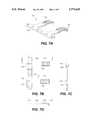
- FIG. 7Ais a perspective view of the sheath grip member of the invention.
- FIG. 7Bis a plan view of the sheath grip member
- FIG. 7Cis an end view of the sheath grip member
- FIG. 7Dis a cross-section of the sheath grip member taken along the line III--III of FIG. 7B;
- FIG. 8Ais a perspective view of the central strength member anchor
- FIG. 8Bis an elevation view of the central strength member anchor
- FIG. 8Cis a plan view of the underside of the central strength member anchor.
- FIG. 1there is shown a closure 10 which embodies the principles and features of the present invention.
- the closure 10comprises a hollow cylindrical cover member 11 of suitable material such as a rigid plastic, and has a closed end 12 and an open end 13.
- a one piece end plate 14is adapted to fit over the open end 13 of member 11, and to be clamped thereto by means of over-center clamps 16 which engage lugs 17 on end plate 14.
- An O-ring 18 of suitable resilient materialrides in a channel 19 in the end plate 14 and produces an extremely water tight and air tight seal when plate 14 is clamped to cover 11.
- Plate 14has formed therein first and second elliptically shaped bores 21 and 22 which extend therethrough. Bores 21 and 22 provide ingress and egress of optical fiber cables (not shown) which pass through resilient grommets 23 of suitable elastomeric material, only one of which is shown.
- the grommets 23are of a standard design which is widely used in the communications industry, as shown in U.S. Pat. No. 5,481,639 of Cobb et al, 5,185,845 of Jones, and 5,280,556 of Jones.
- Each grommet 23has first and second bores 24, 26 therethrough, each of which surrounds and grips a cable so that when a cable containing grommet 23 is inserted in its bore 21, for example, substantially completely water tight and air tight seals between the cable and the grommet 23 and between the grommet 23, which fills the opening or bore 21, and the end plate 14 are produced.
- bore 21is being used, hence, bore 22 is plugged and sealed by the combination of a port plug 27 and O-ring 28.
- a grommet retainer member 29is mounted to the exterior of the end plate 14 by means of a double threaded end stud 31, nut 32, and clamping knob 33, as will be discussed more fully hereinafter.
- Bolt 31also functions to mount a backbone or support member 34 to the inner face 36 of plate 14, that is, the face that faces the interior of the closure 10.
- backbone member 34is located and held in proper position relative to bores 21 and 22 by means of locating pins 37 and 38 which fit into corresponding holes, not shown, in the rear wall 39 of backbone member 34.
- a cantilever cable sheath grip 41is mounted to the rearwardly extending platform 42 by means of bolts 43 which are received in elongated threaded bosses 44.
- a distribution organizer member 48to which is removably mounted a splice tray 49.
- Bolts 46also function to secure a central strength member anchor means 51 to the underside of organizer 48.
- Splice tray 49is adapted to hold a plurality of stacked splice holders 52 which are held in place by means of a splice holder lid 53 and a latch 54.
- the organizer 48which is supported by the backbone member 34 at its proximal end is supported within the cover member 11 by a support member 56 which has fingers 57 and 58 which snap into slots, not shown, in organizer 48.
- the closed end 12 of cover 11has a lug 59 formed thereon and a corresponding lugs 61 and 62 are formed on grommet retainer member 29.
- lug 61 or 62is aligned with lug 59 so that a mounting bracket 63 having legs 64 and 66 is mounted to the lugs 59 and 61 or 62 by means of bolts 67 and 68 and nuts 69 and 71.
- Bracket 63makes possible the mounting of closure 11 to a wall, a pole, an aerial strand or a cabinet, or other location having members, not shown, which fit within holes 72 and 73 on bracket 63. It is to be understood that many different types of brackets can be used, depending upon the application.
- closure assembly 10 of FIG. 1is both simple and compact, and is relatively easily assembled or dis-assembled.
- the backbone member 34firmly supports all of the necessary operative portions of assembly, including the organizer 48, splice tray 49, cable sheath grip 41, the central strength member anchor 51, and, by means of, stud 31 which is anchored thereto by anchor means 45, such as a nut, end plate 14 and grommet retainer 29.
- knob 33affords a measure of adjustment of tightness of the grommet retainer 29 relative to the grommets and of the backbone plate relative to the grommets, and overcenter clamps 16 insure that O-ring 18 forms a water and air tight seal between end plate 14 and the cover 11, thereby obviating the necessity of using an encapsulant.
- the integrity of the seals of O-ring 19 and grommet 33can be checked after assembly by the introduction of air under pressure through an air inlet valve, not shown, which can be screwed into a boss 74 after which test the air inlet opening can be sealed by a pipe plug 76. The pressurized air may tend to push the grommet 23 outward, thereby destroying its seal.
- the grommet retainer 29prevents the grommet 23 from moving in the outward direction. Also, outside forces or pressures such as water or ice pressure may tend to force the grommets inwardly, but the rear wall 39 of the backbone member 34 prevents inward movement of the grommet or grommets. Movement of the cable within the grommet is substantially prevented by means of the cable sheath grip clamped to the cable by suitable clamps, not shown, sufficiently to maintain the integrity of the grommet seal. It can be seen, therefore, that those forces or movements which might destroy the seals are either prevented or resisted so that there is maintained, after assembly, a closure whose water tight and air tight integrity is not compromised.
- FIG. 2 Ais a perspective view of the assembled element of the closure 10, ready for insertion into the cylindrical cover member 11, and FIG. 2B is a perspective view of the assembled closure 10 with the cover member 11 in place.
- all of the operative parts discussed in relation to FIG. 1form a single unitary assembly by virtue of the backbone member 34 to which they are all, either directly or indirectly, attached, and the end plate 14 of the unitary assembly is firmly held against the cover 11 to insure a water and air tight seal.
- FIG. 3Ais a plan view of the assembly of FIG. 2A
- FIG. 3Bis an end elevation view of the assembly of FIG. 2A
- FIG. 3Cis a cross-sectional view of the assembly of FIG. 2A taken along the line I--I of FIG. 3A.
- FIG. 3Aillustrates the unitary nature of the assembly of FIG. 2A and depicts the relationship of the bosses 44 and 47 at the rear of the platform 42 of the backbone 34.
- FIG. 3Bis of particular interest in that it illustrates how grommet retainer member 29 bears against one of the grommet 23, shown in dashed lines and prevents outward movement thereof.
- Retainer member 29has first and second openings 77 and 78 in the wall 79 thereof, which openings are smaller than the openings 21 and 22 of the end plate 14, and hence are smaller than the grommet or grommets 23, but large enough to allow the cables to pass therethrough.
- FIG. 3Cillustrates the relationship of grommet retainer 27, which bears against one end of the grommet (not shown), the backbone member 34, which bears against the other end of the grommet, the threaded bolt or stud 31, and the knob 33. IT can be seen that when knob 33 is tightened members 27 and 34 exert some pressure on the grommet which, being elastomeric, will tend to expand to fill bore 21 completely, thereby creating a strong seal.
- the grommetis prevented from moving in an axial direction regardless of outside or interior forces thereon.
- the backbone or support 34is held in place against the inner face 36 of end plate 14 by means of the stud 31, and is properly oriented by locating pins 37 and 38. It is within the scope of the present invention that the backbone 34 be an integral part of plate 14, in which case retainer 29 would supply the desired pressure against grommet 23.
- FIGS. 4A and 4Bare perspective views of the front and rear, respectively of grommet retainer member 29.
- wall 79 of retainer 29has first and second openings 77 and 78 therein, as previously discussed.
- Adjacent the openings 77 and 78are cable supports 75 upon which the cables rest.
- strength ribs 81 and 82are on the front of member 29 and spaced from each other to accommodate a boss 83 having a bore 84 extending therethrough for passage of the stud 31.
- Boss 83provides a surface against which knob 33 bears.
- first and second walls 86 and 87which, together, substantially surround the openings 77 and 78 and which are configured to fit over elliptical bosses 88 and 89 on end plate 14, best seen in Fig., 5C. these walls insure proper location and orientation of retainer member 29 relative to end plate 14.
- FIG. 5Ais an elevation view of the interior face 36 of end plate 14
- FIG. 5Bis a side elevation view of the end plate 14
- FIG. 5Cis an elevation view of the exterior face of end plate 14 showing, in particular, the configuration of bosses 88 and 89.
- Plate 14is provided with a central bore 91 to allow passage of stud 31 therethrough which has a hexagonally shaped countersink 92 extending inwardly from face 36, as best seen in FIG. 5B.
- Countersink 92is intended to receive a hexagonal section 93 formed on stud 31 to affix the stud in place with the desired degree of length extending in both directions from hexagonal member 93.
- Locating pin 37 and 38extend from the face 36 for providing precise location of the backbone 34, which is shown in dashed outline in FIG. 5A.
- On the outer edge of end plate 14is a locating slot 94, which is positioned to receive a locating lug 96 which is located on the open end rim of cover member 11.
- Elliptical bosses 88 and 89receive the grommet 23 and either a second grommet 23 or a port plug 27 and O-ring 28 therein.
- the grommet 23completely fills the opening 21 and creates a waterproof and air tight seal between it and the opening 21.
- the outer walls of the bosses 88 and 89are shaped and dimensioned to receive the openings in the grommet retainer member 29 defined by the walls 86 and 87, preferably in a slip fit.
- FIG. 6Ais a plan view of the top side of the backbone or support member 34
- FIG. 6Bis an elevation view of the front of the backbone 34
- FIG. 6Cis a cross-sectional elevation view of the backbone 42 taken along the line II--II of FIG. 2A.
- the wall 39i.e., the wall that bears against surface 36 of end plate 14, has a roughly hour-glass shape, as best seen in FIG. 6B, and also as shown in dash lines in FIG. 5A.
- Each of the lobes 97 and 98 of wall 39has a locating hole 99 and 101, respectively, spaced and dimensioned to receive the locating pins 37 and 38, respectively, projecting from surface 36 of the end plate 14.
- the rear surface of wall 39has means forming first and second flanges 102 and 103 thereon which project into the open spaces between the lobes 97 and 98, and, as best seen in FIG. 5A, partially block openings 21 and 22.
- grommets 23have transverse slits for facilitating passing the cables therethrough, thus creating grommet sections which can move relative to each other, which can destroy the seal.
- Flanges 102 and 103prevent such independent movement of the sections.
- Flanges 102 and 103also serve to prevent inward movement of grommets 23 and thus help hold the grommets firmly in place within the bores 21 and 22, despite the presence of external forces, for example.
- the wall/flange assemblyhas a central bore 104 therein for passage of stud or bolt 31.
- ribs 106 and 107which support planar platform 42, which has an array of elongated bosses 44 extending therefrom on each side of the platform, as best seen in FIG. 6C.
- the distal or rear edge of platform 42has bosses 47 formed thereon, as shown in FIG. 6A, which may be threaded or may serve as bearing surfaces for nuts for the bolts 46 which extend therein or therethrough.
- Platform 42also has a cut-out portion 108 for providing room for a nut 45, shown in FIG. 3C, which anchors backbone 34 to stud 31 and endplate 14.
- FIG. 7Ais a perspective view of the cable sheath grip member 41 which, when mounted to the backbone 34 by means of bolts 43 and bosses 44, serves to grip the cable sheaths where terminated to prevent longitudinal movement of the cable which might break its seal within the grommets 23.
- member 41has a square U-shape comprising first and second arms 109 and 111 extending from a cross-arm or base 112. Each arm has a distal end 113 and 114, respectively formed as a U-shaped channel having serrations on the edges for gripping the cable sheath.
- the sheath grip member 41is capable of gripping a wide range of cable diameters, and, to insure positive gripping of small diameter cables, each of the channels 113 and 114 has rearwardly facing barbs or teeth 116 which insure gripping of the cable sheath when it is too small in diameter to be adequately gripped by the serrations in channels 113 and 114.
- Member 41also has a plurality of spaced mounting holes 117 in the crossarm for mounting member 41 to the elongated bosses 44 and hence to the backbone 34.
- FIG. 7Dis a cross-sectional view of cable sheath grip member 41 taken along the line III--III of FIG. 7B, and shows the configuration of the barbs 116.
- base 112can be separated into two non-contacting parts.
- FIG. 8Ais a perspective view of the anchor member of the invention
- FIGS. 8B and 8Care elevation and plan views respectively of member 51.
- One popular configuration of optical fiber cableis the loose tube cable, in which a tubular member surrounds a plurality of buffered tubes containing fibers which are loosely bunched therein or wound around a strength member.
- Such a cablerequires a strength member which usually extends roughly down the center of the tubular member.
- the sheath grip membermight not adequately immobilize the cable, hence a unit such as anchor member 51 is used to accomplish the desired immobilization.
- the unit 51comprises a base member or plate 118 having mounting holes 119 spaced therealong for mounting the unit 51 to bosses 47 by means of bolts 46. Extending from plate 118 are first and second spaced stanchions 121 and 122, the distal ends of which have enlarged portions 123 and 124, respectively, having bores 126 and 127 extending therethrough for receiving the central strength member, and clamping screws 128 and 129 for clamping the central strength members within the bores 126 and 127.
- Assembly of the closureis relatively simple and can be performed on site or in the field without the expenditure of a large amount of time.
- the procedure for assemblycomprises attaching the sheath grip to the cables, then inserting them into the grommet 23, then inserting the grommet into the end plate, attaching the sheath grip to the backbone and mounting the retainer.
- the organizer 48 and tray 49are assembled together and mounted to the backbone 34 along with central strength member anchor 51.
- Knob 33is then tightened on stud 31 to form a unitary assembly.
- the fibersare then separated from each other and routed in a manner similar to that shown in U.S. Pats. No.
- the closure of the inventionis compact, relatively flight weight, and possesses, when assembled, a high degree of isolation of the interior from ambient atmosphere and moisture.
- the high sealing integrityis reproducible, that is, the closure may be opened so that work may be performed on the fibers and fiber splices or cables added, and then reassembled with the same high sealing integrity.
- the use of encapsulantis obviated, which materially facilitates opening the closure and adding cables, and relieves the installer or maintenance person of having to re-encapsulate the interior parts the closure.
Landscapes
- Physics & Mathematics (AREA)
- General Physics & Mathematics (AREA)
- Optics & Photonics (AREA)
- Cable Accessories (AREA)
Abstract
Description
Claims (20)
Priority Applications (1)
| Application Number | Priority Date | Filing Date | Title |
|---|---|---|---|
| US08/773,811US5774618A (en) | 1996-12-19 | 1996-12-19 | Compact closure for optical fiber cable |
Applications Claiming Priority (1)
| Application Number | Priority Date | Filing Date | Title |
|---|---|---|---|
| US08/773,811US5774618A (en) | 1996-12-19 | 1996-12-19 | Compact closure for optical fiber cable |
Publications (1)
| Publication Number | Publication Date |
|---|---|
| US5774618Atrue US5774618A (en) | 1998-06-30 |
Family
ID=25099380
Family Applications (1)
| Application Number | Title | Priority Date | Filing Date |
|---|---|---|---|
| US08/773,811Expired - LifetimeUS5774618A (en) | 1996-12-19 | 1996-12-19 | Compact closure for optical fiber cable |
Country Status (1)
| Country | Link |
|---|---|
| US (1) | US5774618A (en) |
Cited By (32)
| Publication number | Priority date | Publication date | Assignee | Title |
|---|---|---|---|---|
| US5937130A (en)* | 1998-04-20 | 1999-08-10 | Amberg; Mark F. | Method and apparatus for installing fiber optic jumper cables in an equipment enclosure |
| US5995700A (en)* | 1998-01-15 | 1999-11-30 | Lucent Technologies Inc. | Mass fusion splice tray |
| US6052504A (en)* | 1995-04-12 | 2000-04-18 | Rxs Kabelgarnituren Gmbh | Hood sleeve |
| EP1160608A3 (en)* | 2000-05-29 | 2003-07-23 | Fibot Holding Ltd. | Connection container for optical and/or copper mixed cables |
| WO2004079680A1 (en)* | 2003-03-03 | 2004-09-16 | Kwan-Suk Yang | Optical fiber fixing device and invader sensing system having the optical fiber fixing device |
| US7045710B1 (en) | 2005-08-31 | 2006-05-16 | 3M Innovative Properties Company | Enclosure for telecommunication lines and splices |
| US20060122715A1 (en)* | 2004-12-07 | 2006-06-08 | Alliance Laundry Systems Lc | Controller for bridging a host computer and networked laundry machines |
| US20060193587A1 (en)* | 2005-02-25 | 2006-08-31 | Charles Industries, Ltd. | Fiber optic splice enclosure |
| US20070047895A1 (en)* | 2005-08-31 | 2007-03-01 | 3M Innovative Properties Company | Enclosure and organizer for telecommunication lines and splices |
| US20070183732A1 (en)* | 2006-02-08 | 2007-08-09 | Charles Industries, Ltd. | Fiber optic splice enclosure |
| US7351909B1 (en) | 2004-06-10 | 2008-04-01 | Charles Industries, Ltd. | Multilayered housing for electronics enclosures |
| WO2008104282A1 (en)* | 2007-03-01 | 2008-09-04 | Adc Gmbh | Sleeve for optical waveguide cables |
| US20090103877A1 (en)* | 2006-05-30 | 2009-04-23 | Wolf Kluwe | Cable Sleeve for the Structured Storage and Handling of Optical Waveguides Guided in Optical Waveguide Cables |
| US20090103876A1 (en)* | 2006-05-30 | 2009-04-23 | Wolf Kluwe | Cable Sleeve for the Structured Storage and Handling of Optical Waveguides Guided in Optical Waveguide Cables |
| US20090297112A1 (en)* | 2004-03-08 | 2009-12-03 | Adc Telecommunications, Inc. | Fiber access terminal |
| US20100061692A1 (en)* | 2007-03-01 | 2010-03-11 | Adc Gmbh | Multifiber loose buffer receiving element for a distributing device for optical waveguides |
| US20100150515A1 (en)* | 2007-03-01 | 2010-06-17 | Adc Gmbh | Carrier system for mounting telecommunication and data technology devices |
| US20100183275A1 (en)* | 2007-03-01 | 2010-07-22 | Adc Gmbh | Carrier system for a distributing device for optical waveguides |
| WO2011009034A1 (en)* | 2009-07-16 | 2011-01-20 | Afl Telecommunications Llc | Cable retention bracket |
| WO2012162497A1 (en)* | 2011-05-24 | 2012-11-29 | Corning Cable Systems Llc | Three-cable port grommet washer |
| WO2014005919A3 (en)* | 2012-07-02 | 2014-04-03 | Tyco Electronics Raychem Bvba | Seal actuator with actuation level indicator |
| US20140314387A1 (en)* | 2013-04-18 | 2014-10-23 | Furukawa Industrial S.A. Produtos Eletricos | Aerial splicebox for fiber optic cables |
| WO2014128138A3 (en)* | 2013-02-19 | 2014-12-04 | Tyco Electronics Raychem Bvba | Re-enterable enclosure and configuration for mounting |
| EP2136118B1 (en) | 2008-06-16 | 2015-07-01 | Optotec S.p.A. | Device for sealing cables through containers for optical fibres and container comprising said device |
| US9400363B2 (en) | 2012-07-02 | 2016-07-26 | CommScope Connectivity Belgium BVBA | Pressure actuated sealant assembly |
| US9502878B2 (en) | 2012-07-02 | 2016-11-22 | CommScope Connectivity Belgium BVBA | Re-enterable enclosure |
| WO2017045049A1 (en)* | 2015-09-17 | 2017-03-23 | Furukawa Industrial S.A. Produtos Eletronicos | Optical termination box |
| US9685776B2 (en) | 2012-07-02 | 2017-06-20 | CommScope Connectivity Belgium BVBA | Cable sealing unit with multiple sealing modules |
| US9768604B2 (en) | 2009-12-03 | 2017-09-19 | CommScope Connectivity Belgium BVBA | Gel sealing device |
| US9829665B1 (en) | 2017-04-27 | 2017-11-28 | Afl Telecommunications Llc | Fiber optic splice enclosures |
| EP3474054A1 (en)* | 2017-10-18 | 2019-04-24 | Huawei Technologies Co., Ltd. | Fiber optic closure and fiber optic network distribution system |
| EP4369069A3 (en)* | 2022-11-09 | 2024-07-17 | Go!Foton Holdings, Inc. | Modules for spliced cable connections |
Citations (10)
| Publication number | Priority date | Publication date | Assignee | Title |
|---|---|---|---|---|
| US4679896A (en)* | 1985-09-27 | 1987-07-14 | Preformed Line Products Company | Optical fiber splice organizer |
| US4913522A (en)* | 1984-04-11 | 1990-04-03 | Nv Raychem Sa | Electrofit fibre optics butt splice |
| US5097529A (en)* | 1991-03-22 | 1992-03-17 | At&T Bell Laboratories | Space-saving optical fiber cable closure |
| US5185845A (en)* | 1990-12-13 | 1993-02-09 | At&T Bell Laboratories | Optical fiber closure having enhanced storage capability |
| US5255337A (en)* | 1989-01-17 | 1993-10-19 | N.V. Raychem S.A. | Splice case for optical fibre cable |
| US5280556A (en)* | 1992-09-25 | 1994-01-18 | At&T Bell Laboratories | Cable closure which includes a cable sheath gripping assembly |
| US5481639A (en)* | 1994-10-28 | 1996-01-02 | At&T Corp. | Compact closure for optical fiber cable |
| US5568584A (en)* | 1995-03-20 | 1996-10-22 | Psi Telecommunications, Inc. | Fiber optic closure with cable adapter spool |
| US5596670A (en)* | 1993-12-09 | 1997-01-21 | Northern Telecom Limited | Optical fiber cable enclosure |
| US5617501A (en)* | 1995-03-31 | 1997-04-01 | Minnesota Mining And Manufacturing Company | Shield bond strain connector for fiber optic closure |
- 1996
- 1996-12-19USUS08/773,811patent/US5774618A/ennot_activeExpired - Lifetime
Patent Citations (10)
| Publication number | Priority date | Publication date | Assignee | Title |
|---|---|---|---|---|
| US4913522A (en)* | 1984-04-11 | 1990-04-03 | Nv Raychem Sa | Electrofit fibre optics butt splice |
| US4679896A (en)* | 1985-09-27 | 1987-07-14 | Preformed Line Products Company | Optical fiber splice organizer |
| US5255337A (en)* | 1989-01-17 | 1993-10-19 | N.V. Raychem S.A. | Splice case for optical fibre cable |
| US5185845A (en)* | 1990-12-13 | 1993-02-09 | At&T Bell Laboratories | Optical fiber closure having enhanced storage capability |
| US5097529A (en)* | 1991-03-22 | 1992-03-17 | At&T Bell Laboratories | Space-saving optical fiber cable closure |
| US5280556A (en)* | 1992-09-25 | 1994-01-18 | At&T Bell Laboratories | Cable closure which includes a cable sheath gripping assembly |
| US5596670A (en)* | 1993-12-09 | 1997-01-21 | Northern Telecom Limited | Optical fiber cable enclosure |
| US5481639A (en)* | 1994-10-28 | 1996-01-02 | At&T Corp. | Compact closure for optical fiber cable |
| US5568584A (en)* | 1995-03-20 | 1996-10-22 | Psi Telecommunications, Inc. | Fiber optic closure with cable adapter spool |
| US5617501A (en)* | 1995-03-31 | 1997-04-01 | Minnesota Mining And Manufacturing Company | Shield bond strain connector for fiber optic closure |
Cited By (65)
| Publication number | Priority date | Publication date | Assignee | Title |
|---|---|---|---|---|
| US6052504A (en)* | 1995-04-12 | 2000-04-18 | Rxs Kabelgarnituren Gmbh | Hood sleeve |
| US5995700A (en)* | 1998-01-15 | 1999-11-30 | Lucent Technologies Inc. | Mass fusion splice tray |
| US5937130A (en)* | 1998-04-20 | 1999-08-10 | Amberg; Mark F. | Method and apparatus for installing fiber optic jumper cables in an equipment enclosure |
| EP1160608A3 (en)* | 2000-05-29 | 2003-07-23 | Fibot Holding Ltd. | Connection container for optical and/or copper mixed cables |
| WO2004079680A1 (en)* | 2003-03-03 | 2004-09-16 | Kwan-Suk Yang | Optical fiber fixing device and invader sensing system having the optical fiber fixing device |
| EP2267503A1 (en)* | 2004-03-08 | 2010-12-29 | ADC Telecommunications, Inc. | Fiber access terminal |
| US20090297112A1 (en)* | 2004-03-08 | 2009-12-03 | Adc Telecommunications, Inc. | Fiber access terminal |
| US7941027B2 (en) | 2004-03-08 | 2011-05-10 | Adc Telecommunications, Inc. | Fiber access terminal |
| US8363999B2 (en) | 2004-03-08 | 2013-01-29 | Adc Telecommunications, Inc. | Fiber access terminal |
| US7351909B1 (en) | 2004-06-10 | 2008-04-01 | Charles Industries, Ltd. | Multilayered housing for electronics enclosures |
| US20060122715A1 (en)* | 2004-12-07 | 2006-06-08 | Alliance Laundry Systems Lc | Controller for bridging a host computer and networked laundry machines |
| US7274850B2 (en)* | 2005-02-25 | 2007-09-25 | Charles Industries, Ltd. | Fiber optic splice enclosure |
| US20060193587A1 (en)* | 2005-02-25 | 2006-08-31 | Charles Industries, Ltd. | Fiber optic splice enclosure |
| US7333706B2 (en) | 2005-08-31 | 2008-02-19 | 3M Innovative Properties Company | Enclosure and organizer for telecommunication lines and splices |
| US20070047895A1 (en)* | 2005-08-31 | 2007-03-01 | 3M Innovative Properties Company | Enclosure and organizer for telecommunication lines and splices |
| US7045710B1 (en) | 2005-08-31 | 2006-05-16 | 3M Innovative Properties Company | Enclosure for telecommunication lines and splices |
| US20070183732A1 (en)* | 2006-02-08 | 2007-08-09 | Charles Industries, Ltd. | Fiber optic splice enclosure |
| US7418183B2 (en) | 2006-02-08 | 2008-08-26 | Charles Industries, Ltd. | Fiber optic splice enclosure |
| US8055114B2 (en) | 2006-05-30 | 2011-11-08 | Ccs Technology, Inc. | Cable sleeve for the structured storage and handling of optical waveguides guided in optical waveguide cables |
| US20090103876A1 (en)* | 2006-05-30 | 2009-04-23 | Wolf Kluwe | Cable Sleeve for the Structured Storage and Handling of Optical Waveguides Guided in Optical Waveguide Cables |
| US7689090B2 (en)* | 2006-05-30 | 2010-03-30 | Ccs Technology, Inc. | Cable sleeve for the structured storage and handling of optical waveguides guided in optical waveguide cables |
| US20090103877A1 (en)* | 2006-05-30 | 2009-04-23 | Wolf Kluwe | Cable Sleeve for the Structured Storage and Handling of Optical Waveguides Guided in Optical Waveguide Cables |
| US20100061686A1 (en)* | 2007-03-01 | 2010-03-11 | Adc Gmbh | Sleeve for optical waveguide cables |
| US20100150515A1 (en)* | 2007-03-01 | 2010-06-17 | Adc Gmbh | Carrier system for mounting telecommunication and data technology devices |
| WO2008104282A1 (en)* | 2007-03-01 | 2008-09-04 | Adc Gmbh | Sleeve for optical waveguide cables |
| US20100183275A1 (en)* | 2007-03-01 | 2010-07-22 | Adc Gmbh | Carrier system for a distributing device for optical waveguides |
| US20100061692A1 (en)* | 2007-03-01 | 2010-03-11 | Adc Gmbh | Multifiber loose buffer receiving element for a distributing device for optical waveguides |
| US8121455B2 (en) | 2007-03-01 | 2012-02-21 | Adc Gmbh | Carrier system for mounting telecommunication and data technology devices |
| US8280215B2 (en) | 2007-03-01 | 2012-10-02 | Adc Gmbh | Multifiber loose buffer receiving element for a distributing device for optical waveguides |
| EP2136118B1 (en) | 2008-06-16 | 2015-07-01 | Optotec S.p.A. | Device for sealing cables through containers for optical fibres and container comprising said device |
| US20110194829A1 (en)* | 2009-07-16 | 2011-08-11 | Afl Telecommunications Llc | Optical ground wire cable retention bracket |
| WO2011009034A1 (en)* | 2009-07-16 | 2011-01-20 | Afl Telecommunications Llc | Cable retention bracket |
| US11784480B2 (en) | 2009-12-03 | 2023-10-10 | CommScope Connectivity Belgium BVBA | Gel sealing device |
| US10910810B2 (en) | 2009-12-03 | 2021-02-02 | CommScope Connectivity Belgium BVBA | Gel sealing device |
| US10298003B2 (en) | 2009-12-03 | 2019-05-21 | CommScope Connectivity Belgium BVBA | Gel sealing device |
| US9768604B2 (en) | 2009-12-03 | 2017-09-19 | CommScope Connectivity Belgium BVBA | Gel sealing device |
| US8735744B2 (en) | 2011-05-24 | 2014-05-27 | Corning Cable Systems Llc | Three-cable port grommet washer |
| WO2012162497A1 (en)* | 2011-05-24 | 2012-11-29 | Corning Cable Systems Llc | Three-cable port grommet washer |
| US10084302B2 (en) | 2012-07-02 | 2018-09-25 | CommScope Connectivity Belgium BVBA | Re-enterable enclosure |
| US10680426B2 (en) | 2012-07-02 | 2020-06-09 | CommScope Connectivity Belgium BVBA | Cable sealing unit with multiple sealing modules |
| US9502878B2 (en) | 2012-07-02 | 2016-11-22 | CommScope Connectivity Belgium BVBA | Re-enterable enclosure |
| US12218493B2 (en) | 2012-07-02 | 2025-02-04 | CommScope Connectivity Belgium BVBA | Cable sealing unit with multiple sealing modules |
| US9632268B2 (en) | 2012-07-02 | 2017-04-25 | CommScope Connectivity Belgium BVBA | Pressure actuated sealant assembly |
| US11658471B2 (en) | 2012-07-02 | 2023-05-23 | CommScope Connectivity Belgium BVBA | Cable sealing unit with multiple sealing modules |
| US9685776B2 (en) | 2012-07-02 | 2017-06-20 | CommScope Connectivity Belgium BVBA | Cable sealing unit with multiple sealing modules |
| US10951017B2 (en) | 2012-07-02 | 2021-03-16 | CommScope Connectivity Belgium BVBA | Cable sealing unit with multiple sealing modules |
| US9753237B2 (en) | 2012-07-02 | 2017-09-05 | CommScope Connectivity Belgium BVBA | Seal actuator with actuation level indicator |
| WO2014005919A3 (en)* | 2012-07-02 | 2014-04-03 | Tyco Electronics Raychem Bvba | Seal actuator with actuation level indicator |
| US10411455B2 (en) | 2012-07-02 | 2019-09-10 | CommScope Connectivity Belgium BVBA | Re-enterable enclosure |
| US10393978B2 (en) | 2012-07-02 | 2019-08-27 | CommScope Connectivity Belgium BVBA | Seal actuator with actuation level indicator |
| US9400363B2 (en) | 2012-07-02 | 2016-07-26 | CommScope Connectivity Belgium BVBA | Pressure actuated sealant assembly |
| US11973329B2 (en) | 2012-07-02 | 2024-04-30 | CommScope Connectivity Belgium BVBA | Cable sealing unit with multiple sealing modules |
| US9948082B2 (en) | 2012-07-02 | 2018-04-17 | CommScope Connectivity Belgium BVBA | Cable sealing unit with multiple sealing modules |
| RU2651797C2 (en)* | 2013-02-19 | 2018-04-27 | Тайко Электроникс Райхем Бвба | Re-enterable enclosure and configuration for mounting |
| WO2014128138A3 (en)* | 2013-02-19 | 2014-12-04 | Tyco Electronics Raychem Bvba | Re-enterable enclosure and configuration for mounting |
| AU2014220747B2 (en)* | 2013-02-19 | 2017-07-20 | CommScope Connectivity Belgium BVBA | Re-enterable enclosure and configuration for mounting |
| US9647437B2 (en) | 2013-02-19 | 2017-05-09 | CommScope Connectivity Belgium BVBA | Re-enterable enclosure and configuration for mounting |
| CN105122567A (en)* | 2013-02-19 | 2015-12-02 | 泰科电子瑞侃有限公司 | Re-enterable enclosure and configuration for mounting |
| US20140314387A1 (en)* | 2013-04-18 | 2014-10-23 | Furukawa Industrial S.A. Produtos Eletricos | Aerial splicebox for fiber optic cables |
| US9310579B2 (en)* | 2013-04-18 | 2016-04-12 | Furukawa Industrial S.A. Produtos Eletricos | Aerial splicebox for fiber optic cables |
| WO2017045049A1 (en)* | 2015-09-17 | 2017-03-23 | Furukawa Industrial S.A. Produtos Eletronicos | Optical termination box |
| US10241287B2 (en) | 2017-04-27 | 2019-03-26 | Afl Telecommunications Llc | Fiber optic splice enclosures |
| US9829665B1 (en) | 2017-04-27 | 2017-11-28 | Afl Telecommunications Llc | Fiber optic splice enclosures |
| EP3474054A1 (en)* | 2017-10-18 | 2019-04-24 | Huawei Technologies Co., Ltd. | Fiber optic closure and fiber optic network distribution system |
| EP4369069A3 (en)* | 2022-11-09 | 2024-07-17 | Go!Foton Holdings, Inc. | Modules for spliced cable connections |
Similar Documents
| Publication | Publication Date | Title |
|---|---|---|
| US5774618A (en) | Compact closure for optical fiber cable | |
| CA2001584C (en) | Optical fiber cable closure | |
| US5472160A (en) | Splice closure and grip block | |
| US5519804A (en) | Universal splice tray | |
| AU659959B2 (en) | Cable closure which includes a cable sheath gripping assembly | |
| EP2834693B1 (en) | Cable clamp and telecommunications enclosure | |
| EP2277241B1 (en) | Telecommunications cable inlet device | |
| US5121458A (en) | Preterminated fiber optic cable | |
| US4991928A (en) | Movable clamp for fiber optic enclosures | |
| US5420957A (en) | Optical fiber cable splitter | |
| US5689607A (en) | Device for holding at least one optical fiber cable, and a splice box making use of the device | |
| US5097529A (en) | Space-saving optical fiber cable closure | |
| KR19980703282A (en) | Dome type closure for optical fiber | |
| JP2011525695A (en) | Telecommunications cable entry device | |
| US4802724A (en) | Reserve device for optical fibers | |
| KR19980703324A (en) | Fiber optic splice structure | |
| WO2010047920A2 (en) | Mechanical cable entry port | |
| KR19980703325A (en) | Closure to reduce strain on cable | |
| US5862291A (en) | Cable routing device | |
| US5760332A (en) | Cable splice protector | |
| US6266471B1 (en) | Splice closure universal grip block | |
| US11852883B2 (en) | Cable clamp and telecommunications enclosure | |
| GB2425365A (en) | Seal for cable gland assembly and tool therefor | |
| JPH09312927A (en) | Cable introduction hole sealing member | |
| US6094518A (en) | Fiber optic cable restoration enclosure |
Legal Events
| Date | Code | Title | Description |
|---|---|---|---|
| AS | Assignment | Owner name:LUCENT TECHNOLOGIES, INC., NEW JERSEY Free format text:ASSIGNMENT OF ASSIGNORS INTEREST;ASSIGNOR:JONES, WESLEY WILLING;REEL/FRAME:008379/0562 Effective date:19961218 | |
| STCF | Information on status: patent grant | Free format text:PATENTED CASE | |
| FEPP | Fee payment procedure | Free format text:PAYOR NUMBER ASSIGNED (ORIGINAL EVENT CODE: ASPN); ENTITY STATUS OF PATENT OWNER: LARGE ENTITY | |
| AS | Assignment | Owner name:THE CHASE MANHATTAN BANK, AS COLLATERAL AGENT, TEX Free format text:CONDITIONAL ASSIGNMENT OF AND SECURITY INTEREST IN PATENT RIGHTS;ASSIGNOR:LUCENT TECHNOLOGIES INC. (DE CORPORATION);REEL/FRAME:011722/0048 Effective date:20010222 | |
| FPAY | Fee payment | Year of fee payment:4 | |
| AS | Assignment | Owner name:LUCENT TECHNOLOGIES INC., NEW JERSEY Free format text:PARTIAL TERMINATION AND RELEASE OF SECURITY INTEREST.;ASSIGNOR:JPMORGAN CHASE BANK (F/K/A THE CHASE MANHATTAN BANK);REEL/FRAME:012495/0128 Effective date:20011116 | |
| AS | Assignment | Owner name:FITEL USA CORPORATION, GEORGIA Free format text:ASSIGNMENT OF ASSIGNORS INTEREST;ASSIGNOR:LUCENT TECHNOLOGIES;REEL/FRAME:012946/0578 Effective date:20011116 | |
| FPAY | Fee payment | Year of fee payment:8 | |
| SULP | Surcharge for late payment | Year of fee payment:7 | |
| FPAY | Fee payment | Year of fee payment:12 | |
| AS | Assignment | Owner name:FURUKAWA ELECTRIC NORTH AMERICA, INC., GEORGIA Free format text:CHANGE OF NAME;ASSIGNOR:FITEL USA CORP.;REEL/FRAME:025521/0684 Effective date:20031218 |