US5774501A - High speed multilevel symbol telemetry system for cardiac pacemakers - Google Patents
High speed multilevel symbol telemetry system for cardiac pacemakersDownload PDFInfo
- Publication number
- US5774501A US5774501AUS08/547,394US54739495AUS5774501AUS 5774501 AUS5774501 AUS 5774501AUS 54739495 AUS54739495 AUS 54739495AUS 5774501 AUS5774501 AUS 5774501A
- Authority
- US
- United States
- Prior art keywords
- symbols
- symbol
- frequency
- waves
- transmitter
- Prior art date
- Legal status (The legal status is an assumption and is not a legal conclusion. Google has not performed a legal analysis and makes no representation as to the accuracy of the status listed.)
- Expired - Fee Related
Links
- 230000000747cardiac effectEffects0.000titleclaimsdescription5
- 230000005540biological transmissionEffects0.000claimsabstractdescription6
- 238000004891communicationMethods0.000claimsdescription26
- 239000003990capacitorSubstances0.000claimsdescription25
- 238000000034methodMethods0.000claimsdescription7
- 230000001419dependent effectEffects0.000claimsdescription3
- 238000000638solvent extractionMethods0.000claims2
- 230000003213activating effectEffects0.000claims1
- 239000007943implantSubstances0.000description12
- 238000010586diagramMethods0.000description7
- 230000008878couplingEffects0.000description3
- 238000010168coupling processMethods0.000description3
- 238000005859coupling reactionMethods0.000description3
- 238000009432framingMethods0.000description3
- 230000004048modificationEffects0.000description3
- 238000012986modificationMethods0.000description3
- RTAQQCXQSZGOHL-UHFFFAOYSA-NTitaniumChemical compound[Ti]RTAQQCXQSZGOHL-UHFFFAOYSA-N0.000description2
- 230000000694effectsEffects0.000description2
- 230000001939inductive effectEffects0.000description2
- 230000036962time dependentEffects0.000description2
- 229910052719titaniumInorganic materials0.000description2
- 239000010936titaniumSubstances0.000description2
- 229910001069Ti alloyInorganic materials0.000description1
- 230000001154acute effectEffects0.000description1
- 230000008859changeEffects0.000description1
- 239000013078crystalSubstances0.000description1
- 230000001862defibrillatory effectEffects0.000description1
- 238000001514detection methodMethods0.000description1
- 238000001914filtrationMethods0.000description1
- 230000006870functionEffects0.000description1
- 238000002513implantationMethods0.000description1
- 230000001788irregularEffects0.000description1
- 239000000463materialSubstances0.000description1
- 238000005192partitionMethods0.000description1
- 230000008569processEffects0.000description1
- 230000002441reversible effectEffects0.000description1
- 238000000926separation methodMethods0.000description1
Images


Classifications
- A—HUMAN NECESSITIES
- A61—MEDICAL OR VETERINARY SCIENCE; HYGIENE
- A61N—ELECTROTHERAPY; MAGNETOTHERAPY; RADIATION THERAPY; ULTRASOUND THERAPY
- A61N1/00—Electrotherapy; Circuits therefor
- A61N1/18—Applying electric currents by contact electrodes
- A61N1/32—Applying electric currents by contact electrodes alternating or intermittent currents
- A61N1/36—Applying electric currents by contact electrodes alternating or intermittent currents for stimulation
- A61N1/372—Arrangements in connection with the implantation of stimulators
- A61N1/37211—Means for communicating with stimulators
- A61N1/37252—Details of algorithms or data aspects of communication system, e.g. handshaking, transmitting specific data or segmenting data
- A61N1/37254—Pacemaker or defibrillator security, e.g. to prevent or inhibit programming alterations by hackers or unauthorised individuals
Definitions
- This inventionpertains to an apparatus incorporated in implantable pacemakers and the like constructed and arranged to provide high speed communication between the pacemakers and the outside world.
- the inventionfurther pertains to a method of operating said apparatus.
- pacemakersalso brought on an increase in the amount of information that must be exchanged between the pacemaker and the external devices, such as, for example, a programmer used by a physician to initialize a pacemaker, monitor its operation and change its operational parameters, if required.
- Pacemakersare able to communicate to external devices by using an inductive coupling type of telemetry means.
- the devices known to the inventorsare limited to schemes using pulse position, FSK or phase modulation. These schemes were limited to only one bit per baud which severely limits the transmission baud rate. Moreover the frequency of operation of these devices was limited to a low range because of the low pass filter characteristics of the pacemakers' titanium casing to about 8000 bits/second.
- U.S. Pat No. 4,453,162discloses a telemetry system utilizing a tuned LC circuit as the transceiver element.
- U.S. Pat. No. 4,944,299discloses a telemetry system using a switched LC circuit to generate PSK modulation wherein a prescribed correlation is used between the transmitter and the receiver.
- U.S. Pat. No. 5,342,408discloses a telemetry system with various types of communication protocols.
- FIG. 1Ashows another prior art communication scheme.
- This schemeconsists essentially of 488 microsecond (usec) baud periods. Within each baud period, four cosine waves represent one symbol and three cosine waves represent a second symbol. Importantly, the phase and frequency of the waves remains constant.
- a further objective of the inventionis to provide an apparatus with a low power consumption.
- Yet a further objectiveis to provide a telemetry apparatus for a pacemaker with a minimum number of parts so that it does not increase the size of the pacemaker housing.
- a communication system constructed in accordance with this inventionconsists of a pair of inductors, one in the implant and the other in the programmer. Means are provided in the implant for forming two tank circuits, each said tank circuit having a resonant frequency. In the transmitting mode, one or the other of the tank circuits are enabled to generate cosine waves. By selecting the frequency and phase of each, a plurality of symbols is defined, each symbol corresponding to one of several binary bits. In the receiving mode, a matched filter network is used to extract the cosine waves which are then decoded. Preferably, a fixed frame is transmitted by the implant, having a blanking period reserved for reverse transmission, i.e., from the programmer to the implant.
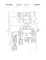
- FIG. 1shows a block diagram of the telemetering system constructed in accordance with this invention
- FIG. 1Ashows a prior art communication scheme
- FIG. 2shows details of the transmitter for the implant telemetering section of FIG. 1;
- FIG. 3shows a block diagram of the telemetering system of a programmer constructed in accordance with this invention
- FIG. 4shows a proposed communication scheme
- FIG. 5Ashows a time dependent chart of a first modification to the scheme modification of FIG. 4;
- FIG. 5Bshows a time-dependent chart of a second modification in accordance with the present invention
- FIG. 6shows a constellation diagram for the transmitted and received symbols for FIGS. 5A and 5B;
- FIG. 7shows typical received signal and the corresponding signals from the matched filter
- FIG. 8shows as the structure of a communication frame in accordance with the invention.
- a pacemaker system 10is illustrated consisting of an implant 12 and a programmer 14.
- the implant 12consists of a housing 16 which is preferably made of a titanium alloy or other similar material.
- a crystal oscillator 18operating at a frequency of 32.798 kHz. This signal is normally referred to as a 32 kHz signal and is identified in the Figure as 32Ck.
- This oscillatorprovides clocking pulses for various pacemaker functions which do not form part of the present invention.
- the output of the oscillator 18is also fed to a frequency divider network which divides this frequency to provide a nominal 8 Khz and 16 Khz clocking signal, identified in FIG. 1 as 8Ck and Ck16 respectively.
- the actual frequency of these signalsare 8.192 kHz and 16.384 kHz, respectively.
- the implant 12further includes a transmitter 22, a receiver 24 and a common coil 26. Data for transmission by transmitter 22 is stored in a transmit data memory 28 and data received by receiver 24 is stored in a data receive memory 30.
- the implant 12is designed and constructed to transmit and receive data at one of several baud rates.
- the implant 12includes a data rate selector 30.
- the data rate selectorgenerates a control signal on line 32 to designate the data rate to be used by the transmitter 22 and receiver 24.
- the programmer 14includes a programmer wand 34 holding a coil 36.
- the programmer 14further includes a programmer housing 38 coupled to wand 34 by a pair of wires 40. Inside the programmer housing there is provided a transmitter section 42 and a receiver section 44, each being coupled to the coil 36 through wires 40 as shown.
- the transmitter section 22includes a plurality of switches labeled SW1-9, a first capacitor CA and a second capacitor CB.
- Switches SW1-9are electronic switches operated by a switch controller 50.
- Switch SW1selectively connects the switching network to battery 52.
- Controller 50receives the clock signals 32CK, 16CK, 8CK and 4CK, data signals X1, X2 from memory 28, and the bit rate selector signal on line 32 from data rate selector 30.
- the receiver section 44 in the programmer 14includes an amplifier 60 receiving a signal V picked up by coil 36.
- the output of amplifier 60is fed to a low pass filter 62 provided to eliminate higher frequency noise above 32 kHz.
- the filtered signal Ris fed to a zero crossing sync circuit 64 and a matched filter network 66.
- the outputs of the filter networkare fed to a pair of comparators 72, 74 and to an inverter 80.
- the outputs of the comparatorsare fed to a decoder 76.
- Pacemaker systemshave special communication requirements, including low power, low frequency and low bandwidth.
- inductive couplingall switching must occur while the current through the inductor is minimal.
- FIG. 4A PSK-type communication scheme is shown in FIG. 4.
- signalsare transmitted sequentially with a baud period BP of 122 us (microseconds).
- each symbolconsists of either a full positive cosine wave (such as symbols 52, 54, 58) or a negative cosine wave (symbol 56).
- These full wavesare assigned binary values.
- waves 52, 54, 58maybe assigned a binary value of ⁇ 1 ⁇ and wave 56 may be assigned a binary value of ⁇ 0 ⁇ .
- the wavesare not ideal but rather they drop in amplitude from the maximum point 60 to point 62 by a differential amount dV. This drop is due to the resistive losses in the tank circuit used to generate the waves, as described below.
- the frequency of the waves 52-58is nominally 8 kHz. Importantly, every wave 52-58 starts at its maximum absolute amplitude, i.e. when the current through the inductor used for coupling is zero. In this manner the transmitter can switch from one symbol to the other without waiting for the current in the inductance to decay. This is an important consideration in pacemakers since the current through the implant inductor should not be switched. In addition, switching during low current levels is advantageous because it saves power and reduces intersymbol interference. A drawback of the scheme shown in FIG. 4 is that it provides a data rate which is still relatively slow as discussed above.
- FIG. 5AAn improved communication is shown in FIG. 5A.
- the first symbol B1(similar to symbols 52, 54 and 58) is a positive cosine wave and the second symbol B2 (similar to symbol 56 in FIG. 4) is a negative cosine wave, each wave consisting of a full cycle having nominal frequency of 8 kHz.
- FIG. 5Ashows two more symbols, B3 and B4, which are used in accordance with this invention in conjunction with symbols B1 and B2 to effectively double the data rate of the scheme, while using the same baud rate.
- Symbols B3 and B4consist of positive cosine and negative cosine waves, each cosine wave consisting of two cycles having a nominal frequency of 16 kHz and a baud period of 122 us.
- the symbols B1, B2, B3 and B4may be advantageously represented on a constellation chart as shown in FIG. 6, wherein the symbols B1 and B2 defined by the 8 kHz cosine waves are disposed on the horizontal axis and the symbols B3 and B4 defined by the 16 kHz cosine waves are disposed along the vertical axis.
- the symbols B1, B2, B3 and B4are assigned two bits each, such as (0,0), (0,1), (1,0) and (1,1) respectively.
- the data rate of the scheme of FIG. 5Aincreased from 8000 bits/second to 16,000 bits/second at the same baud rate of 8000.
- FIG. 5BAnother communication scheme is shown in FIG. 5B.
- the baud periodhas been reduced by 50% from the one in FIG. 5A, i.e. to 61 us.
- two bitsmay be assigned to each symbol, as shown. In this manner, the nominal rate is increased to 32K bits/sec while the frequency of the symbols remain the same.
- the position of these symbols D1-D4 on the constellation diagram of FIG. 5Bis identical to the positions of symbols B1-B4.
- the switch controller 50receives all the clock signals CK4, CK8, CK16 and CK32, as well as the data signals X1, X2 and the data rate control signal DR on line 32. Based on the data rate designated by the control signal DR, and the binary data X1, X2, the controller then selectively operates the switches SW1-SW9 for transmitting each corresponding baud. This latter signal defines the data rate of the transmitter.
- a tapped inductormay be used to form a tank circuit having one of two resonant frequencies.
- switch SW1closes for a very short time period.
- switches SW2 and SW5also closed thereby charging capacitor CA to voltage +V.
- switch SW1opens and the charged capacitor is now connected to the inductor 26 by closing switches SW6 and SW9.
- the tank circuit thus formedstarts resonating at 8 kHz and is interrupted after 61 us (microseconds) to define one half cycle of the positive cosine wave shown in FIG. 5B.
- the switches SW6 and SW9are opened thereby completing symbol D1.
- capacitor CAis charged to a negative voltage (-V) offset by Vd from the initial voltage due to resistive losses in the tank circuit.
- the polarity of the voltage on CAis reversed by enabling switches SW4 and SW3. This reversal causes the polarity of the voltage on CA to be the same as the polarity of the battery from which CA will be charged. In this manner, significant battery energy is saved.
- capacitor CAis used to generate the 8 kHz symbols D1, D2. If the next 8 kHz symbol consists of a 1/2 cycle of a negative cosine wave (i.e., D2) then the capacitor CA is coupled to the coil L through switches SW3, SW4, SW7 and SW8.
- the capacitor CAis discharged through switches SW3, and SW4 and switches SW6 and SW9.
- the capacitor CAis charged to the voltage +V through switches SW3 and SW4, and is discharged either through SW6/SW9 or SW7/SW8.
- the voltage across capacitor CAmay be replenished by closing either SW2/SW5 or SW3/SW4.
- the 16 kHz waveformsare generate by using capacitor CB.
- a separate switch bridgemay be provided similar to the one shown for capacitor CA.
- a single switch SW5Amay be used to control the tank circuit, and a switch bridge may be provided for the inductor L.
- the capacitor CBis first charged by closing switches SW1 and SW5A.
- the resonating tank circuitis formed by opening SW1 and connecting capacitor CB to the coil 16 through switches SW6 and SW9 for a period equal to the resonant period of the tank circuit. At the end of the period, the capacitor is charged to +V less dV. If the next baud is D3, the same processes are repeated. If the next symbol is D4, then the capacitor CB is connected to the inductor 16 through switches SW7 and SW8 thereby providing a phase reversal.
- the scheme shown in FIG. 5Amay be implemented the same way except for the duration of the baud period. Alternately, in this scheme, at the end of each cosine wave, the capacitor CB is refreshed as discussed above, and as shown in FIG. 5A at 52, 54.
- the system 10is operated in half-duplex mode.
- the capacitors CA, CB and battery 52are disconnected and the inductor is connected through switches SW 6 and SW 9 to the receiver 24.
- the inductor 36is inductively coupled to the inductor 26 and is disposed in a programmer wand.
- the inductor 36is coupled to an operational amplifier 60 (the switches of FIG. 3 have been omitted for the sake of simplicity).
- Amplifier 60which incorporates a low pas filter to eliminate noise.
- the output of amplifier 62is fed to a zero crossing detector/synchronizer 64, as well as to a matched filter network 66 used for decoding the signals received from the inductor L.
- the symbols generated by the transmitter of FIG. 2are represented as idealized points B1-B4.
- the signals received by the inductor 36appear on the diagram as four clouds of points, such clouds R1, R2, R3, R4, each being disposed in a somewhat irregular fashion around the respective transmitted points B1-B4.
- Two diagonal axes Z1 and Z2 drawn through the origin of the constellation diagrampartition the constellation diagram into four quadrants Q1-Q4, each quadrant containing one of the clouds. Any symbol received can then be designated as corresponding to one of the points B1-B4 dependent on the respective quadrant.
- each point of cloud R1is disposed in quadrant Q1 and hence it corresponds to transmitted symbol B1
- each point of cloud R2can be designated as corresponding to transmitted point B2, and so on.
- the signals thus generatedare decoded as shown in FIG. 3.
- the matched filter network 66is used to extract from its input signal R: a +8 kHz sine signal (S); a +8 kHz cosine signal (C8); and a +16 kHz cosine signal (C16). This last signal is also inverted by inverter 80 to generate -16 kHz cosine signal (-C16). Since the maximum amplitudes of these signals may be different, an equalizer means, such as a resistive network may be included in the filter network to insure that the components have the same peak magnitudes.
- the signals S, C8, C16 and -C16are derived by the filter network using standard filtering and phase matching techniques.
- a typical received signal R and the resulting componentsare illustrated in FIG. 7, together with the signal across coil L and the output R of amplifier 62. These signals are typical for a 6 cm separation between a transmitter and receiver coil. Therefore at the beginning of each frame (described below) the component S is fed to the zero crossing/sync circuit 64 which generates a SYNC signal indicative of these zero crossings.
- This sync signalis used to synchronize the output CK of a 16 kHz clock generator 70.
- the CK clock signalenables the two comparators 72, 74.
- Comparator 72when enabled (or latched) compares the components C8 and C16. In effect the comparator 72 makes a decision as to whether a receive symbol is on one side of axis Z1 or the other. More particularly, if component C8 is larger than C16 then the received symbol must be in quadrants Q1 or Q4. Otherwise, the received symbol must be in quadrant Q2 or Q3.
- comparator 74makes a decision on whether the received symbol is on one side or the other of axis Z2. If the component C8 is larger than component C16 then the received symbol must be in quadrants Q2 or Q4. Otherwise the received symbol must be in quadrant Q1 or Q3.
- the outputs of comparators 72 and 74are fed to a decoder 76 which then makes a decision identifying the quadrant corresponding to the received symbol R and generates two binary bits for the symbol. This decision is based on the following table:
- a typical frame transmitted by the pacemakeris shown in FIG. 8. It consists of a quiet period 80 having a duration, for example of 488 us. The quiet period is used to announce to the programmer that a new frame is to be expected. This quiet period 80 may also be used by the programmer to generate its own data to the pacemaker.
- the quiet periodis followed by a dedicated initial symbol 82.
- the symbol 82is a half cycle of an 8 kHz cosine signal shown in FIG. 7. This signal is used by the network 66 to generate the sine output (signal S) needed to synchronize the programmer clock to the received signal as described above.
- the external sync signalis followed by a data block 84 of a predetermined number of symbols.
- the duration of the data block 84is preferably in the range of 75 periods of the 8 kHz signal, i.e. , 9.75 ms.
- the number of symbolsis dependent on the encoding scheme used, as described above.
- This sync and framing techniqueis advantageous because it allows communication to occur at an efficiency exceeding 90% while in prior communication schemes only a 75% efficiency was achieved. Because the bandwidth is so limited intersymbol interference, occurs. Viterbi decoding may be used to significantly reduce the effect of this ISI. If the communication channel is noisy or other sources of errors degrade the performance of the scheme, an error detection/correction scheme may be used.
- the data rate for the schememay be determined by the programmer based, for example, on error rates.
- Signals from the programmer to the implantmay be transmitted using any prior art schemes such as pulse position modulation. This scheme is preferred because it is simple to implement and has low power requirements.
Landscapes
- Health & Medical Sciences (AREA)
- Life Sciences & Earth Sciences (AREA)
- Biophysics (AREA)
- Heart & Thoracic Surgery (AREA)
- Engineering & Computer Science (AREA)
- Biomedical Technology (AREA)
- Nuclear Medicine, Radiotherapy & Molecular Imaging (AREA)
- Radiology & Medical Imaging (AREA)
- Animal Behavior & Ethology (AREA)
- General Health & Medical Sciences (AREA)
- Public Health (AREA)
- Veterinary Medicine (AREA)
- Electrotherapy Devices (AREA)
Abstract
Description
______________________________________ Frame Baud Bit Rate (BPS) Length (ms) Interval (us) Symbols ______________________________________ 1.5 K 4 488 4 cycles of± 8kHz 8K 10 122 1 cycle of ± 8 kHz16K 10 122 1 cycle of ± 8 kHz 2 cycles of ± 16kHz 32K 10 61 1/2 cycle of ± 8 kHz 1 cycle of ± 16 kHz ______________________________________
______________________________________COMPARATOR 72COMPARATOR 74 ______________________________________ 1 0 0Q1 Q2 1 Q3 Q4 ______________________________________
Claims (30)
Priority Applications (2)
| Application Number | Priority Date | Filing Date | Title |
|---|---|---|---|
| US08/547,394US5774501A (en) | 1995-10-24 | 1995-10-24 | High speed multilevel symbol telemetry system for cardiac pacemakers |
| EP96307712AEP0771575A3 (en) | 1995-10-24 | 1996-10-24 | High speed multilevel symbol telemetry system for cardiac pacemakers |
Applications Claiming Priority (1)
| Application Number | Priority Date | Filing Date | Title |
|---|---|---|---|
| US08/547,394US5774501A (en) | 1995-10-24 | 1995-10-24 | High speed multilevel symbol telemetry system for cardiac pacemakers |
Publications (1)
| Publication Number | Publication Date |
|---|---|
| US5774501Atrue US5774501A (en) | 1998-06-30 |
Family
ID=24184495
Family Applications (1)
| Application Number | Title | Priority Date | Filing Date |
|---|---|---|---|
| US08/547,394Expired - Fee RelatedUS5774501A (en) | 1995-10-24 | 1995-10-24 | High speed multilevel symbol telemetry system for cardiac pacemakers |
Country Status (2)
| Country | Link |
|---|---|
| US (1) | US5774501A (en) |
| EP (1) | EP0771575A3 (en) |
Cited By (106)
| Publication number | Priority date | Publication date | Assignee | Title |
|---|---|---|---|---|
| US6201993B1 (en)* | 1998-12-09 | 2001-03-13 | Medtronic, Inc. | Medical device telemetry receiver having improved noise discrimination |
| US6329929B1 (en)* | 1998-12-21 | 2001-12-11 | Medtronic Inc. | Telemetry system with phase-locking noise suppressing receiver |
| US20040049246A1 (en)* | 2000-06-19 | 2004-03-11 | Medtronic, Inc. | Implantable medical device telemetry processor |
| US6711440B2 (en) | 2002-04-11 | 2004-03-23 | Biophan Technologies, Inc. | MRI-compatible medical device with passive generation of optical sensing signals |
| US6718207B2 (en) | 2001-02-20 | 2004-04-06 | Biophan Technologies, Inc. | Electromagnetic interference immune tissue invasive system |
| US6725092B2 (en) | 2002-04-25 | 2004-04-20 | Biophan Technologies, Inc. | Electromagnetic radiation immune medical assist device adapter |
| US6731979B2 (en) | 2001-08-30 | 2004-05-04 | Biophan Technologies Inc. | Pulse width cardiac pacing apparatus |
| US20040116981A1 (en)* | 2002-12-13 | 2004-06-17 | Cardiac Pacemakers, Inc. | Device communications of an implantable medical device and an external system |
| US20040122488A1 (en)* | 2002-12-23 | 2004-06-24 | Cardiac Pacemakers, Inc. | Method and apparatus for enabling data communication between an implantable medical device and a patient management system |
| US20040122489A1 (en)* | 2002-12-23 | 2004-06-24 | Cardiac Pacemakers, Inc. | Implantable medical device having long-term wireless capabilities |
| US20040128161A1 (en)* | 2002-12-27 | 2004-07-01 | Mazar Scott T. | System and method for ad hoc communications with an implantable medical device |
| US6829509B1 (en) | 2001-02-20 | 2004-12-07 | Biophan Technologies, Inc. | Electromagnetic interference immune tissue invasive system |
| US6925328B2 (en) | 2000-04-20 | 2005-08-02 | Biophan Technologies, Inc. | MRI-compatible implantable device |
| US6968236B2 (en) | 2002-01-28 | 2005-11-22 | Biophan Technologies, Inc. | Ceramic cardiac electrodes |
| US6978182B2 (en) | 2002-12-27 | 2005-12-20 | Cardiac Pacemakers, Inc. | Advanced patient management system including interrogator/transceiver unit |
| US6980848B2 (en) | 2002-07-25 | 2005-12-27 | Biopham Technologies Inc. | Optical MRI catheter system |
| US6988001B2 (en) | 2001-10-31 | 2006-01-17 | Biophan Technologies, Inc. | Hermetic component housing for photonic catheter |
| US7009511B2 (en) | 2002-12-17 | 2006-03-07 | Cardiac Pacemakers, Inc. | Repeater device for communications with an implantable medical device |
| US20060089856A1 (en)* | 2004-10-21 | 2006-04-27 | Cardiac Pacemakers | Integrated pharmaceutical dispensing and patient management monitoring |
| US20060089592A1 (en)* | 2004-10-21 | 2006-04-27 | Cardiac Pacemakers, Inc. | Systems and methods for drug therapy enhancement using expected pharmacodynamic models |
| US7054686B2 (en) | 2001-08-30 | 2006-05-30 | Biophan Technologies, Inc. | Pulsewidth electrical stimulation |
| US20070011028A1 (en)* | 2005-07-05 | 2007-01-11 | Cardiac Pacemakers, Inc. | Optimization of timing for data collection and analysis in advanced patient management system |
| US20120183095A1 (en)* | 2011-01-18 | 2012-07-19 | Qualcomm Incorporated | Apparatus and method for signalling carrier combination capabilities for a multi-carrier multi-band wireless communication system |
| US8527046B2 (en) | 2000-04-20 | 2013-09-03 | Medtronic, Inc. | MRI-compatible implantable device |
| US9001750B2 (en) | 2010-04-05 | 2015-04-07 | Qualcomm Incorporated | Method and apparatus for signaling user equipment capabilities |
| US9002467B2 (en) | 2005-05-18 | 2015-04-07 | Cardiac Pacemakers, Inc. | Modular antitachyarrhythmia therapy system |
| US9526909B2 (en) | 2014-08-28 | 2016-12-27 | Cardiac Pacemakers, Inc. | Medical device with triggered blanking period |
| US9592391B2 (en) | 2014-01-10 | 2017-03-14 | Cardiac Pacemakers, Inc. | Systems and methods for detecting cardiac arrhythmias |
| US9669230B2 (en) | 2015-02-06 | 2017-06-06 | Cardiac Pacemakers, Inc. | Systems and methods for treating cardiac arrhythmias |
| US9853743B2 (en) | 2015-08-20 | 2017-12-26 | Cardiac Pacemakers, Inc. | Systems and methods for communication between medical devices |
| US9956414B2 (en) | 2015-08-27 | 2018-05-01 | Cardiac Pacemakers, Inc. | Temporal configuration of a motion sensor in an implantable medical device |
| US9968787B2 (en) | 2015-08-27 | 2018-05-15 | Cardiac Pacemakers, Inc. | Spatial configuration of a motion sensor in an implantable medical device |
| US10029107B1 (en) | 2017-01-26 | 2018-07-24 | Cardiac Pacemakers, Inc. | Leadless device with overmolded components |
| US10046167B2 (en) | 2015-02-09 | 2018-08-14 | Cardiac Pacemakers, Inc. | Implantable medical device with radiopaque ID tag |
| US10050700B2 (en) | 2015-03-18 | 2018-08-14 | Cardiac Pacemakers, Inc. | Communications in a medical device system with temporal optimization |
| US10065041B2 (en) | 2015-10-08 | 2018-09-04 | Cardiac Pacemakers, Inc. | Devices and methods for adjusting pacing rates in an implantable medical device |
| US10092760B2 (en) | 2015-09-11 | 2018-10-09 | Cardiac Pacemakers, Inc. | Arrhythmia detection and confirmation |
| US10137305B2 (en) | 2015-08-28 | 2018-11-27 | Cardiac Pacemakers, Inc. | Systems and methods for behaviorally responsive signal detection and therapy delivery |
| US10159842B2 (en) | 2015-08-28 | 2018-12-25 | Cardiac Pacemakers, Inc. | System and method for detecting tamponade |
| US10183170B2 (en) | 2015-12-17 | 2019-01-22 | Cardiac Pacemakers, Inc. | Conducted communication in a medical device system |
| US10213610B2 (en) | 2015-03-18 | 2019-02-26 | Cardiac Pacemakers, Inc. | Communications in a medical device system with link quality assessment |
| US10220213B2 (en) | 2015-02-06 | 2019-03-05 | Cardiac Pacemakers, Inc. | Systems and methods for safe delivery of electrical stimulation therapy |
| US10226631B2 (en) | 2015-08-28 | 2019-03-12 | Cardiac Pacemakers, Inc. | Systems and methods for infarct detection |
| US10328272B2 (en) | 2016-05-10 | 2019-06-25 | Cardiac Pacemakers, Inc. | Retrievability for implantable medical devices |
| US10350423B2 (en) | 2016-02-04 | 2019-07-16 | Cardiac Pacemakers, Inc. | Delivery system with force sensor for leadless cardiac device |
| US10357159B2 (en) | 2015-08-20 | 2019-07-23 | Cardiac Pacemakers, Inc | Systems and methods for communication between medical devices |
| US10391319B2 (en) | 2016-08-19 | 2019-08-27 | Cardiac Pacemakers, Inc. | Trans septal implantable medical device |
| US10413733B2 (en) | 2016-10-27 | 2019-09-17 | Cardiac Pacemakers, Inc. | Implantable medical device with gyroscope |
| US10426962B2 (en) | 2016-07-07 | 2019-10-01 | Cardiac Pacemakers, Inc. | Leadless pacemaker using pressure measurements for pacing capture verification |
| US10434317B2 (en) | 2016-10-31 | 2019-10-08 | Cardiac Pacemakers, Inc. | Systems and methods for activity level pacing |
| US10434314B2 (en) | 2016-10-27 | 2019-10-08 | Cardiac Pacemakers, Inc. | Use of a separate device in managing the pace pulse energy of a cardiac pacemaker |
| US10463305B2 (en) | 2016-10-27 | 2019-11-05 | Cardiac Pacemakers, Inc. | Multi-device cardiac resynchronization therapy with timing enhancements |
| US10512784B2 (en) | 2016-06-27 | 2019-12-24 | Cardiac Pacemakers, Inc. | Cardiac therapy system using subcutaneously sensed P-waves for resynchronization pacing management |
| US10561330B2 (en) | 2016-10-27 | 2020-02-18 | Cardiac Pacemakers, Inc. | Implantable medical device having a sense channel with performance adjustment |
| US10583303B2 (en) | 2016-01-19 | 2020-03-10 | Cardiac Pacemakers, Inc. | Devices and methods for wirelessly recharging a rechargeable battery of an implantable medical device |
| US10583301B2 (en) | 2016-11-08 | 2020-03-10 | Cardiac Pacemakers, Inc. | Implantable medical device for atrial deployment |
| US10617874B2 (en) | 2016-10-31 | 2020-04-14 | Cardiac Pacemakers, Inc. | Systems and methods for activity level pacing |
| US10632313B2 (en) | 2016-11-09 | 2020-04-28 | Cardiac Pacemakers, Inc. | Systems, devices, and methods for setting cardiac pacing pulse parameters for a cardiac pacing device |
| US10639486B2 (en) | 2016-11-21 | 2020-05-05 | Cardiac Pacemakers, Inc. | Implantable medical device with recharge coil |
| US10668294B2 (en) | 2016-05-10 | 2020-06-02 | Cardiac Pacemakers, Inc. | Leadless cardiac pacemaker configured for over the wire delivery |
| US10688304B2 (en) | 2016-07-20 | 2020-06-23 | Cardiac Pacemakers, Inc. | Method and system for utilizing an atrial contraction timing fiducial in a leadless cardiac pacemaker system |
| US10722720B2 (en) | 2014-01-10 | 2020-07-28 | Cardiac Pacemakers, Inc. | Methods and systems for improved communication between medical devices |
| US10737102B2 (en) | 2017-01-26 | 2020-08-11 | Cardiac Pacemakers, Inc. | Leadless implantable device with detachable fixation |
| US10758724B2 (en) | 2016-10-27 | 2020-09-01 | Cardiac Pacemakers, Inc. | Implantable medical device delivery system with integrated sensor |
| US10758737B2 (en) | 2016-09-21 | 2020-09-01 | Cardiac Pacemakers, Inc. | Using sensor data from an intracardially implanted medical device to influence operation of an extracardially implantable cardioverter |
| US10765871B2 (en) | 2016-10-27 | 2020-09-08 | Cardiac Pacemakers, Inc. | Implantable medical device with pressure sensor |
| US10780278B2 (en) | 2016-08-24 | 2020-09-22 | Cardiac Pacemakers, Inc. | Integrated multi-device cardiac resynchronization therapy using P-wave to pace timing |
| US10821288B2 (en) | 2017-04-03 | 2020-11-03 | Cardiac Pacemakers, Inc. | Cardiac pacemaker with pacing pulse energy adjustment based on sensed heart rate |
| US10835753B2 (en) | 2017-01-26 | 2020-11-17 | Cardiac Pacemakers, Inc. | Intra-body device communication with redundant message transmission |
| US10870008B2 (en) | 2016-08-24 | 2020-12-22 | Cardiac Pacemakers, Inc. | Cardiac resynchronization using fusion promotion for timing management |
| US10874861B2 (en) | 2018-01-04 | 2020-12-29 | Cardiac Pacemakers, Inc. | Dual chamber pacing without beat-to-beat communication |
| US10881869B2 (en) | 2016-11-21 | 2021-01-05 | Cardiac Pacemakers, Inc. | Wireless re-charge of an implantable medical device |
| US10881863B2 (en) | 2016-11-21 | 2021-01-05 | Cardiac Pacemakers, Inc. | Leadless cardiac pacemaker with multimode communication |
| US10894163B2 (en) | 2016-11-21 | 2021-01-19 | Cardiac Pacemakers, Inc. | LCP based predictive timing for cardiac resynchronization |
| US10905872B2 (en) | 2017-04-03 | 2021-02-02 | Cardiac Pacemakers, Inc. | Implantable medical device with a movable electrode biased toward an extended position |
| US10905889B2 (en) | 2016-09-21 | 2021-02-02 | Cardiac Pacemakers, Inc. | Leadless stimulation device with a housing that houses internal components of the leadless stimulation device and functions as the battery case and a terminal of an internal battery |
| US10905886B2 (en) | 2015-12-28 | 2021-02-02 | Cardiac Pacemakers, Inc. | Implantable medical device for deployment across the atrioventricular septum |
| US10918875B2 (en) | 2017-08-18 | 2021-02-16 | Cardiac Pacemakers, Inc. | Implantable medical device with a flux concentrator and a receiving coil disposed about the flux concentrator |
| US10994145B2 (en) | 2016-09-21 | 2021-05-04 | Cardiac Pacemakers, Inc. | Implantable cardiac monitor |
| US11052258B2 (en) | 2017-12-01 | 2021-07-06 | Cardiac Pacemakers, Inc. | Methods and systems for detecting atrial contraction timing fiducials within a search window from a ventricularly implanted leadless cardiac pacemaker |
| US11058880B2 (en) | 2018-03-23 | 2021-07-13 | Medtronic, Inc. | VFA cardiac therapy for tachycardia |
| US11065459B2 (en) | 2017-08-18 | 2021-07-20 | Cardiac Pacemakers, Inc. | Implantable medical device with pressure sensor |
| US11071870B2 (en) | 2017-12-01 | 2021-07-27 | Cardiac Pacemakers, Inc. | Methods and systems for detecting atrial contraction timing fiducials and determining a cardiac interval from a ventricularly implanted leadless cardiac pacemaker |
| US11116988B2 (en) | 2016-03-31 | 2021-09-14 | Cardiac Pacemakers, Inc. | Implantable medical device with rechargeable battery |
| US11147979B2 (en) | 2016-11-21 | 2021-10-19 | Cardiac Pacemakers, Inc. | Implantable medical device with a magnetically permeable housing and an inductive coil disposed about the housing |
| US11185703B2 (en) | 2017-11-07 | 2021-11-30 | Cardiac Pacemakers, Inc. | Leadless cardiac pacemaker for bundle of his pacing |
| US11207527B2 (en) | 2016-07-06 | 2021-12-28 | Cardiac Pacemakers, Inc. | Method and system for determining an atrial contraction timing fiducial in a leadless cardiac pacemaker system |
| US11207532B2 (en) | 2017-01-04 | 2021-12-28 | Cardiac Pacemakers, Inc. | Dynamic sensing updates using postural input in a multiple device cardiac rhythm management system |
| US11213676B2 (en) | 2019-04-01 | 2022-01-04 | Medtronic, Inc. | Delivery systems for VfA cardiac therapy |
| US11235159B2 (en) | 2018-03-23 | 2022-02-01 | Medtronic, Inc. | VFA cardiac resynchronization therapy |
| US11235163B2 (en) | 2017-09-20 | 2022-02-01 | Cardiac Pacemakers, Inc. | Implantable medical device with multiple modes of operation |
| US11235161B2 (en) | 2018-09-26 | 2022-02-01 | Medtronic, Inc. | Capture in ventricle-from-atrium cardiac therapy |
| US11260216B2 (en) | 2017-12-01 | 2022-03-01 | Cardiac Pacemakers, Inc. | Methods and systems for detecting atrial contraction timing fiducials during ventricular filling from a ventricularly implanted leadless cardiac pacemaker |
| US11285326B2 (en) | 2015-03-04 | 2022-03-29 | Cardiac Pacemakers, Inc. | Systems and methods for treating cardiac arrhythmias |
| US11305127B2 (en) | 2019-08-26 | 2022-04-19 | Medtronic Inc. | VfA delivery and implant region detection |
| US11400296B2 (en) | 2018-03-23 | 2022-08-02 | Medtronic, Inc. | AV synchronous VfA cardiac therapy |
| US11529523B2 (en) | 2018-01-04 | 2022-12-20 | Cardiac Pacemakers, Inc. | Handheld bridge device for providing a communication bridge between an implanted medical device and a smartphone |
| US11679265B2 (en) | 2019-02-14 | 2023-06-20 | Medtronic, Inc. | Lead-in-lead systems and methods for cardiac therapy |
| US11697025B2 (en) | 2019-03-29 | 2023-07-11 | Medtronic, Inc. | Cardiac conduction system capture |
| US11712188B2 (en) | 2019-05-07 | 2023-08-01 | Medtronic, Inc. | Posterior left bundle branch engagement |
| US11813463B2 (en) | 2017-12-01 | 2023-11-14 | Cardiac Pacemakers, Inc. | Leadless cardiac pacemaker with reversionary behavior |
| US11813464B2 (en) | 2020-07-31 | 2023-11-14 | Medtronic, Inc. | Cardiac conduction system evaluation |
| US11813466B2 (en) | 2020-01-27 | 2023-11-14 | Medtronic, Inc. | Atrioventricular nodal stimulation |
| US11911168B2 (en) | 2020-04-03 | 2024-02-27 | Medtronic, Inc. | Cardiac conduction system therapy benefit determination |
| US11951313B2 (en) | 2018-11-17 | 2024-04-09 | Medtronic, Inc. | VFA delivery systems and methods |
| US12296177B2 (en) | 2018-12-21 | 2025-05-13 | Medtronic, Inc. | Delivery systems and methods for left ventricular pacing |
Families Citing this family (1)
| Publication number | Priority date | Publication date | Assignee | Title |
|---|---|---|---|---|
| US7545272B2 (en) | 2005-02-08 | 2009-06-09 | Therasense, Inc. | RF tag on test strips, test strip vials and boxes |
Citations (7)
| Publication number | Priority date | Publication date | Assignee | Title |
|---|---|---|---|---|
| US4223679A (en)* | 1979-02-28 | 1980-09-23 | Pacesetter Systems, Inc. | Telemetry means for tissue stimulator system |
| US4281664A (en)* | 1979-05-14 | 1981-08-04 | Medtronic, Inc. | Implantable telemetry transmission system for analog and digital data |
| US4453162A (en)* | 1982-05-10 | 1984-06-05 | Telectronics Pty. Ltd. | Efficient and fast-switching telemetry transmitter |
| US4847617A (en)* | 1987-08-14 | 1989-07-11 | Siemens-Pacesetter, Inc. | High speed digital telemetry system for implantable devices |
| US4944299A (en)* | 1989-08-08 | 1990-07-31 | Siemens-Pacesetter, Inc. | High speed digital telemetry system for implantable device |
| US4979506A (en)* | 1989-08-08 | 1990-12-25 | Siemens-Pacesetter, Inc. | Self-test system and method for external programming device |
| US5342408A (en)* | 1993-01-07 | 1994-08-30 | Incontrol, Inc. | Telemetry system for an implantable cardiac device |
Family Cites Families (2)
| Publication number | Priority date | Publication date | Assignee | Title |
|---|---|---|---|---|
| US5264843A (en)* | 1989-04-05 | 1993-11-23 | Siemens Pacesetter, Inc. | High speed reflected impedance telemetry system for implantable medical device |
| DE69328406T2 (en)* | 1992-11-20 | 2000-09-14 | Ntt Mobile Communications Network Inc., Tokio/Tokyo | Frequency diversity transmitters and receivers |
- 1995
- 1995-10-24USUS08/547,394patent/US5774501A/ennot_activeExpired - Fee Related
- 1996
- 1996-10-24EPEP96307712Apatent/EP0771575A3/ennot_activeWithdrawn
Patent Citations (7)
| Publication number | Priority date | Publication date | Assignee | Title |
|---|---|---|---|---|
| US4223679A (en)* | 1979-02-28 | 1980-09-23 | Pacesetter Systems, Inc. | Telemetry means for tissue stimulator system |
| US4281664A (en)* | 1979-05-14 | 1981-08-04 | Medtronic, Inc. | Implantable telemetry transmission system for analog and digital data |
| US4453162A (en)* | 1982-05-10 | 1984-06-05 | Telectronics Pty. Ltd. | Efficient and fast-switching telemetry transmitter |
| US4847617A (en)* | 1987-08-14 | 1989-07-11 | Siemens-Pacesetter, Inc. | High speed digital telemetry system for implantable devices |
| US4944299A (en)* | 1989-08-08 | 1990-07-31 | Siemens-Pacesetter, Inc. | High speed digital telemetry system for implantable device |
| US4979506A (en)* | 1989-08-08 | 1990-12-25 | Siemens-Pacesetter, Inc. | Self-test system and method for external programming device |
| US5342408A (en)* | 1993-01-07 | 1994-08-30 | Incontrol, Inc. | Telemetry system for an implantable cardiac device |
Cited By (174)
| Publication number | Priority date | Publication date | Assignee | Title |
|---|---|---|---|---|
| US6201993B1 (en)* | 1998-12-09 | 2001-03-13 | Medtronic, Inc. | Medical device telemetry receiver having improved noise discrimination |
| US6329929B1 (en)* | 1998-12-21 | 2001-12-11 | Medtronic Inc. | Telemetry system with phase-locking noise suppressing receiver |
| US6925328B2 (en) | 2000-04-20 | 2005-08-02 | Biophan Technologies, Inc. | MRI-compatible implantable device |
| US8527046B2 (en) | 2000-04-20 | 2013-09-03 | Medtronic, Inc. | MRI-compatible implantable device |
| US20040049246A1 (en)* | 2000-06-19 | 2004-03-11 | Medtronic, Inc. | Implantable medical device telemetry processor |
| US7610099B2 (en) | 2000-06-19 | 2009-10-27 | Medtronic, Inc. | Method of processing telemetry signals in an implantable medical device including a telemetry processor |
| US7254448B2 (en) | 2000-06-19 | 2007-08-07 | Medtronic, Inc. | Method of operating an implantable medical device telemetry processor |
| US20060287694A1 (en)* | 2000-06-19 | 2006-12-21 | Medtronic, Inc. | Implantable Medical Device Telemetry Processor |
| US6738670B1 (en) | 2000-06-19 | 2004-05-18 | Medtronic, Inc. | Implantable medical device telemetry processor |
| US7450996B2 (en) | 2001-02-20 | 2008-11-11 | Medtronic, Inc. | Medical device with an electrically conductive anti-antenna geometrical shaped member |
| US6850805B2 (en) | 2001-02-20 | 2005-02-01 | Biophan Technologies, Inc. | Electromagnetic interference immune tissue invasive system |
| US6718207B2 (en) | 2001-02-20 | 2004-04-06 | Biophan Technologies, Inc. | Electromagnetic interference immune tissue invasive system |
| US6757566B2 (en) | 2001-02-20 | 2004-06-29 | Biophan Technologies, Inc. | Electromagnetic interference immune tissue invasive system |
| US7010357B2 (en) | 2001-02-20 | 2006-03-07 | Biophan Technologies, Inc. | Electromagnetic interference immune tissue invasive system |
| US6760628B2 (en) | 2001-02-20 | 2004-07-06 | Biophan Technologies, Inc. | Electromagnetic interference immune tissue invasive system |
| US6778856B2 (en) | 2001-02-20 | 2004-08-17 | Biophan Technologies, Inc. | Electromagnetic interference immune tissue invasive system |
| US6795736B2 (en) | 2001-02-20 | 2004-09-21 | Biophan Technologies, Inc. | Electromagnetic interference immune tissue invasive system |
| US6799069B2 (en) | 2001-02-20 | 2004-09-28 | Biophan Technologies, Inc. | Electromagnetic interference immune tissue invasive system |
| US6819958B2 (en) | 2001-02-20 | 2004-11-16 | Biophan Technologies, Inc. | Electromagnetic interference immune tissue invasive system |
| US6819954B2 (en) | 2001-02-20 | 2004-11-16 | Biophan Technologies, Inc. | Electromagnetic interference immune tissue invasive system |
| US6829509B1 (en) | 2001-02-20 | 2004-12-07 | Biophan Technologies, Inc. | Electromagnetic interference immune tissue invasive system |
| US6845266B2 (en) | 2001-02-20 | 2005-01-18 | Biophan Technologies, Inc. | Electromagnetic interference immune tissue invasive system |
| US7047074B2 (en) | 2001-02-20 | 2006-05-16 | Biophan Technologies, Inc. | Electromagnetic interference immune tissue invasive system |
| US6901290B2 (en) | 2001-02-20 | 2005-05-31 | Biophan Technologies, Inc. | Electromagnetic interference immune tissue invasive system |
| US6718203B2 (en) | 2001-02-20 | 2004-04-06 | Biophan Technologies, Inc. | Electromagnetic interference immune tissue invasive system |
| US6954674B2 (en) | 2001-02-20 | 2005-10-11 | Biophan Technologies, Inc. | Electromagnetic interference immune tissue invasive system |
| US7013174B2 (en) | 2001-02-20 | 2006-03-14 | Biophan Technologies, Inc. | Electromagnetic interference immune tissue invasive system |
| US6993387B2 (en) | 2001-02-20 | 2006-01-31 | Biophan Technologies, Inc. | Electromagnetic interference immune tissue invasive system |
| US6731979B2 (en) | 2001-08-30 | 2004-05-04 | Biophan Technologies Inc. | Pulse width cardiac pacing apparatus |
| US7054686B2 (en) | 2001-08-30 | 2006-05-30 | Biophan Technologies, Inc. | Pulsewidth electrical stimulation |
| US6988001B2 (en) | 2001-10-31 | 2006-01-17 | Biophan Technologies, Inc. | Hermetic component housing for photonic catheter |
| US6968236B2 (en) | 2002-01-28 | 2005-11-22 | Biophan Technologies, Inc. | Ceramic cardiac electrodes |
| US6711440B2 (en) | 2002-04-11 | 2004-03-23 | Biophan Technologies, Inc. | MRI-compatible medical device with passive generation of optical sensing signals |
| US6725092B2 (en) | 2002-04-25 | 2004-04-20 | Biophan Technologies, Inc. | Electromagnetic radiation immune medical assist device adapter |
| US7389137B2 (en) | 2002-07-25 | 2008-06-17 | Biophan Technologies, Inc. | Optical MRI catheter system |
| US6980848B2 (en) | 2002-07-25 | 2005-12-27 | Biopham Technologies Inc. | Optical MRI catheter system |
| US7065409B2 (en) | 2002-12-13 | 2006-06-20 | Cardiac Pacemakers, Inc. | Device communications of an implantable medical device and an external system |
| US20040116981A1 (en)* | 2002-12-13 | 2004-06-17 | Cardiac Pacemakers, Inc. | Device communications of an implantable medical device and an external system |
| US7292139B2 (en) | 2002-12-17 | 2007-11-06 | Cardiac Pacemakers, Inc. | Repeater device for communications with an implantable medical device |
| US8451113B2 (en) | 2002-12-17 | 2013-05-28 | Cardiac Pacemakers, Inc. | Repeater providing data exchange with a medical device for remote patient care and method thereof |
| US7791467B2 (en) | 2002-12-17 | 2010-09-07 | Cardiac Pacemakers, Inc. | Repeater providing data exchange with a medical device for remote patient care and method thereof |
| US7009511B2 (en) | 2002-12-17 | 2006-03-07 | Cardiac Pacemakers, Inc. | Repeater device for communications with an implantable medical device |
| US20060121846A1 (en)* | 2002-12-17 | 2006-06-08 | Mazar Scott T | Repeater device for communications with an implantable medical device |
| US20100328062A1 (en)* | 2002-12-17 | 2010-12-30 | Cardiac Pacemakers, Inc. | Repeater Providing Data Exchange with a Medical Device for Remote Patient Care and Method Thereof |
| US8791815B2 (en) | 2002-12-17 | 2014-07-29 | Cardiac Pacemakers, Inc. | System and method providing data exchange with a medical device for remote patient care |
| US8130093B2 (en) | 2002-12-17 | 2012-03-06 | Cardiac Pacemakers, Inc. | Repeater providing data exchange with a medical device for remote patient care and method thereof |
| US7127300B2 (en) | 2002-12-23 | 2006-10-24 | Cardiac Pacemakers, Inc. | Method and apparatus for enabling data communication between an implantable medical device and a patient management system |
| US9114265B2 (en) | 2002-12-23 | 2015-08-25 | Cardiac Pacemakers, Inc. | Method and apparatus for enabling data communication between an implantable medical device and a patient management system |
| US7395117B2 (en) | 2002-12-23 | 2008-07-01 | Cardiac Pacemakers, Inc. | Implantable medical device having long-term wireless capabilities |
| US20080211665A1 (en)* | 2002-12-23 | 2008-09-04 | Cardiac Pacemakers, Inc. | Implantable medical device having long-term wireless capabilities |
| US20070083246A1 (en)* | 2002-12-23 | 2007-04-12 | Cardiac Pacemakers, Inc. | Method and apparatus for enabling data communication between an implantable medical device and a patient management system |
| US9578449B2 (en) | 2002-12-23 | 2017-02-21 | Cardiac Pacemakers, Inc. | Enabling data communication between an implantable medical device and a patient management system |
| US8700172B2 (en) | 2002-12-23 | 2014-04-15 | Cardiac Pacemakers | Implantable medical device having long-term wireless capabilities |
| US9979810B2 (en) | 2002-12-23 | 2018-05-22 | Cardiac Pacemakers, Inc. | Enabling data communication between an implantable medical device and a patient management system |
| US20040122489A1 (en)* | 2002-12-23 | 2004-06-24 | Cardiac Pacemakers, Inc. | Implantable medical device having long-term wireless capabilities |
| US20040122488A1 (en)* | 2002-12-23 | 2004-06-24 | Cardiac Pacemakers, Inc. | Method and apparatus for enabling data communication between an implantable medical device and a patient management system |
| US7751901B2 (en) | 2002-12-27 | 2010-07-06 | Cardiac Pacemakers, Inc. | Advanced patient management system including interrogator/transceiver unit |
| US20040128161A1 (en)* | 2002-12-27 | 2004-07-01 | Mazar Scott T. | System and method for ad hoc communications with an implantable medical device |
| US20060106433A1 (en)* | 2002-12-27 | 2006-05-18 | Cardiac Pacemakers, Inc. | Advanced patient management system including interrogator/transceiver unit |
| US6978182B2 (en) | 2002-12-27 | 2005-12-20 | Cardiac Pacemakers, Inc. | Advanced patient management system including interrogator/transceiver unit |
| US20060089856A1 (en)* | 2004-10-21 | 2006-04-27 | Cardiac Pacemakers | Integrated pharmaceutical dispensing and patient management monitoring |
| US20060089592A1 (en)* | 2004-10-21 | 2006-04-27 | Cardiac Pacemakers, Inc. | Systems and methods for drug therapy enhancement using expected pharmacodynamic models |
| US8150509B2 (en) | 2004-10-21 | 2012-04-03 | Cardiac Pacemakers, Inc. | Systems and methods for drug therapy enhancement using expected pharmacodynamic models |
| US9993654B2 (en) | 2005-05-18 | 2018-06-12 | Cardiac Pacemakers, Inc. | Modular antitachyarrhythmia therapy system |
| US10363428B2 (en) | 2005-05-18 | 2019-07-30 | Cardiac Pacemakers, Inc. | Modular antitachyarrhythmia therapy system |
| US11083898B2 (en) | 2005-05-18 | 2021-08-10 | Cardiac Pacemakers, Inc. | Modular antitachyarrhythmia therapy system |
| US9352164B2 (en) | 2005-05-18 | 2016-05-31 | Cardiac Pacemakers, Inc. | Modular antitachyarrhythmia therapy system |
| US9242113B2 (en) | 2005-05-18 | 2016-01-26 | Cardiac Pacemarkers, Inc. | Modular antitachyarrhythmia therapy system |
| US9002467B2 (en) | 2005-05-18 | 2015-04-07 | Cardiac Pacemakers, Inc. | Modular antitachyarrhythmia therapy system |
| US20070011028A1 (en)* | 2005-07-05 | 2007-01-11 | Cardiac Pacemakers, Inc. | Optimization of timing for data collection and analysis in advanced patient management system |
| US7752059B2 (en) | 2005-07-05 | 2010-07-06 | Cardiac Pacemakers, Inc. | Optimization of timing for data collection and analysis in advanced patient management system |
| US8326652B2 (en) | 2005-07-05 | 2012-12-04 | Cardiac Pacemakers, Inc. | Optimization of timing for data collection and analysis in advanced patient management system |
| US8055517B2 (en) | 2005-07-05 | 2011-11-08 | Cardiac Pacemakers, Inc. | Optimization of timing for data collection and analysis in advanced patient management system |
| US20110071848A1 (en)* | 2005-07-05 | 2011-03-24 | Sweeney Robert J | Optimization of timing for data collection and analysis in advanced patient management system |
| US7860733B2 (en) | 2005-07-05 | 2010-12-28 | Cardiac Pacemakers, Inc. | Optimization of timing for data collection and analysis in advanced patient management system |
| US20100250287A1 (en)* | 2005-07-05 | 2010-09-30 | Sweeney Robert J | Optimization of timing for data collection and analysis in advanced patient management system |
| US9001750B2 (en) | 2010-04-05 | 2015-04-07 | Qualcomm Incorporated | Method and apparatus for signaling user equipment capabilities |
| US20120183095A1 (en)* | 2011-01-18 | 2012-07-19 | Qualcomm Incorporated | Apparatus and method for signalling carrier combination capabilities for a multi-carrier multi-band wireless communication system |
| US10722720B2 (en) | 2014-01-10 | 2020-07-28 | Cardiac Pacemakers, Inc. | Methods and systems for improved communication between medical devices |
| US9592391B2 (en) | 2014-01-10 | 2017-03-14 | Cardiac Pacemakers, Inc. | Systems and methods for detecting cardiac arrhythmias |
| US9526909B2 (en) | 2014-08-28 | 2016-12-27 | Cardiac Pacemakers, Inc. | Medical device with triggered blanking period |
| US10220213B2 (en) | 2015-02-06 | 2019-03-05 | Cardiac Pacemakers, Inc. | Systems and methods for safe delivery of electrical stimulation therapy |
| US11224751B2 (en) | 2015-02-06 | 2022-01-18 | Cardiac Pacemakers, Inc. | Systems and methods for safe delivery of electrical stimulation therapy |
| US9669230B2 (en) | 2015-02-06 | 2017-06-06 | Cardiac Pacemakers, Inc. | Systems and methods for treating cardiac arrhythmias |
| US10238882B2 (en) | 2015-02-06 | 2019-03-26 | Cardiac Pacemakers | Systems and methods for treating cardiac arrhythmias |
| US11020595B2 (en) | 2015-02-06 | 2021-06-01 | Cardiac Pacemakers, Inc. | Systems and methods for treating cardiac arrhythmias |
| US11020600B2 (en) | 2015-02-09 | 2021-06-01 | Cardiac Pacemakers, Inc. | Implantable medical device with radiopaque ID tag |
| US10046167B2 (en) | 2015-02-09 | 2018-08-14 | Cardiac Pacemakers, Inc. | Implantable medical device with radiopaque ID tag |
| US11285326B2 (en) | 2015-03-04 | 2022-03-29 | Cardiac Pacemakers, Inc. | Systems and methods for treating cardiac arrhythmias |
| US10213610B2 (en) | 2015-03-18 | 2019-02-26 | Cardiac Pacemakers, Inc. | Communications in a medical device system with link quality assessment |
| US10946202B2 (en) | 2015-03-18 | 2021-03-16 | Cardiac Pacemakers, Inc. | Communications in a medical device system with link quality assessment |
| US10050700B2 (en) | 2015-03-18 | 2018-08-14 | Cardiac Pacemakers, Inc. | Communications in a medical device system with temporal optimization |
| US11476927B2 (en) | 2015-03-18 | 2022-10-18 | Cardiac Pacemakers, Inc. | Communications in a medical device system with temporal optimization |
| US9853743B2 (en) | 2015-08-20 | 2017-12-26 | Cardiac Pacemakers, Inc. | Systems and methods for communication between medical devices |
| US10357159B2 (en) | 2015-08-20 | 2019-07-23 | Cardiac Pacemakers, Inc | Systems and methods for communication between medical devices |
| US10709892B2 (en) | 2015-08-27 | 2020-07-14 | Cardiac Pacemakers, Inc. | Temporal configuration of a motion sensor in an implantable medical device |
| US9956414B2 (en) | 2015-08-27 | 2018-05-01 | Cardiac Pacemakers, Inc. | Temporal configuration of a motion sensor in an implantable medical device |
| US9968787B2 (en) | 2015-08-27 | 2018-05-15 | Cardiac Pacemakers, Inc. | Spatial configuration of a motion sensor in an implantable medical device |
| US10137305B2 (en) | 2015-08-28 | 2018-11-27 | Cardiac Pacemakers, Inc. | Systems and methods for behaviorally responsive signal detection and therapy delivery |
| US10226631B2 (en) | 2015-08-28 | 2019-03-12 | Cardiac Pacemakers, Inc. | Systems and methods for infarct detection |
| US10589101B2 (en) | 2015-08-28 | 2020-03-17 | Cardiac Pacemakers, Inc. | System and method for detecting tamponade |
| US10159842B2 (en) | 2015-08-28 | 2018-12-25 | Cardiac Pacemakers, Inc. | System and method for detecting tamponade |
| US10092760B2 (en) | 2015-09-11 | 2018-10-09 | Cardiac Pacemakers, Inc. | Arrhythmia detection and confirmation |
| US10065041B2 (en) | 2015-10-08 | 2018-09-04 | Cardiac Pacemakers, Inc. | Devices and methods for adjusting pacing rates in an implantable medical device |
| US10933245B2 (en) | 2015-12-17 | 2021-03-02 | Cardiac Pacemakers, Inc. | Conducted communication in a medical device system |
| US10183170B2 (en) | 2015-12-17 | 2019-01-22 | Cardiac Pacemakers, Inc. | Conducted communication in a medical device system |
| US10905886B2 (en) | 2015-12-28 | 2021-02-02 | Cardiac Pacemakers, Inc. | Implantable medical device for deployment across the atrioventricular septum |
| US10583303B2 (en) | 2016-01-19 | 2020-03-10 | Cardiac Pacemakers, Inc. | Devices and methods for wirelessly recharging a rechargeable battery of an implantable medical device |
| US10350423B2 (en) | 2016-02-04 | 2019-07-16 | Cardiac Pacemakers, Inc. | Delivery system with force sensor for leadless cardiac device |
| US11116988B2 (en) | 2016-03-31 | 2021-09-14 | Cardiac Pacemakers, Inc. | Implantable medical device with rechargeable battery |
| US10668294B2 (en) | 2016-05-10 | 2020-06-02 | Cardiac Pacemakers, Inc. | Leadless cardiac pacemaker configured for over the wire delivery |
| US10328272B2 (en) | 2016-05-10 | 2019-06-25 | Cardiac Pacemakers, Inc. | Retrievability for implantable medical devices |
| US11497921B2 (en) | 2016-06-27 | 2022-11-15 | Cardiac Pacemakers, Inc. | Cardiac therapy system using subcutaneously sensed p-waves for resynchronization pacing management |
| US10512784B2 (en) | 2016-06-27 | 2019-12-24 | Cardiac Pacemakers, Inc. | Cardiac therapy system using subcutaneously sensed P-waves for resynchronization pacing management |
| US11207527B2 (en) | 2016-07-06 | 2021-12-28 | Cardiac Pacemakers, Inc. | Method and system for determining an atrial contraction timing fiducial in a leadless cardiac pacemaker system |
| US10426962B2 (en) | 2016-07-07 | 2019-10-01 | Cardiac Pacemakers, Inc. | Leadless pacemaker using pressure measurements for pacing capture verification |
| US10688304B2 (en) | 2016-07-20 | 2020-06-23 | Cardiac Pacemakers, Inc. | Method and system for utilizing an atrial contraction timing fiducial in a leadless cardiac pacemaker system |
| US10391319B2 (en) | 2016-08-19 | 2019-08-27 | Cardiac Pacemakers, Inc. | Trans septal implantable medical device |
| US10780278B2 (en) | 2016-08-24 | 2020-09-22 | Cardiac Pacemakers, Inc. | Integrated multi-device cardiac resynchronization therapy using P-wave to pace timing |
| US11464982B2 (en) | 2016-08-24 | 2022-10-11 | Cardiac Pacemakers, Inc. | Integrated multi-device cardiac resynchronization therapy using p-wave to pace timing |
| US10870008B2 (en) | 2016-08-24 | 2020-12-22 | Cardiac Pacemakers, Inc. | Cardiac resynchronization using fusion promotion for timing management |
| US10758737B2 (en) | 2016-09-21 | 2020-09-01 | Cardiac Pacemakers, Inc. | Using sensor data from an intracardially implanted medical device to influence operation of an extracardially implantable cardioverter |
| US10994145B2 (en) | 2016-09-21 | 2021-05-04 | Cardiac Pacemakers, Inc. | Implantable cardiac monitor |
| US10905889B2 (en) | 2016-09-21 | 2021-02-02 | Cardiac Pacemakers, Inc. | Leadless stimulation device with a housing that houses internal components of the leadless stimulation device and functions as the battery case and a terminal of an internal battery |
| US11305125B2 (en) | 2016-10-27 | 2022-04-19 | Cardiac Pacemakers, Inc. | Implantable medical device with gyroscope |
| US10758724B2 (en) | 2016-10-27 | 2020-09-01 | Cardiac Pacemakers, Inc. | Implantable medical device delivery system with integrated sensor |
| US10463305B2 (en) | 2016-10-27 | 2019-11-05 | Cardiac Pacemakers, Inc. | Multi-device cardiac resynchronization therapy with timing enhancements |
| US10434314B2 (en) | 2016-10-27 | 2019-10-08 | Cardiac Pacemakers, Inc. | Use of a separate device in managing the pace pulse energy of a cardiac pacemaker |
| US10561330B2 (en) | 2016-10-27 | 2020-02-18 | Cardiac Pacemakers, Inc. | Implantable medical device having a sense channel with performance adjustment |
| US10413733B2 (en) | 2016-10-27 | 2019-09-17 | Cardiac Pacemakers, Inc. | Implantable medical device with gyroscope |
| US10765871B2 (en) | 2016-10-27 | 2020-09-08 | Cardiac Pacemakers, Inc. | Implantable medical device with pressure sensor |
| US10617874B2 (en) | 2016-10-31 | 2020-04-14 | Cardiac Pacemakers, Inc. | Systems and methods for activity level pacing |
| US10434317B2 (en) | 2016-10-31 | 2019-10-08 | Cardiac Pacemakers, Inc. | Systems and methods for activity level pacing |
| US10583301B2 (en) | 2016-11-08 | 2020-03-10 | Cardiac Pacemakers, Inc. | Implantable medical device for atrial deployment |
| US10632313B2 (en) | 2016-11-09 | 2020-04-28 | Cardiac Pacemakers, Inc. | Systems, devices, and methods for setting cardiac pacing pulse parameters for a cardiac pacing device |
| US11147979B2 (en) | 2016-11-21 | 2021-10-19 | Cardiac Pacemakers, Inc. | Implantable medical device with a magnetically permeable housing and an inductive coil disposed about the housing |
| US10881869B2 (en) | 2016-11-21 | 2021-01-05 | Cardiac Pacemakers, Inc. | Wireless re-charge of an implantable medical device |
| US10881863B2 (en) | 2016-11-21 | 2021-01-05 | Cardiac Pacemakers, Inc. | Leadless cardiac pacemaker with multimode communication |
| US10894163B2 (en) | 2016-11-21 | 2021-01-19 | Cardiac Pacemakers, Inc. | LCP based predictive timing for cardiac resynchronization |
| US10639486B2 (en) | 2016-11-21 | 2020-05-05 | Cardiac Pacemakers, Inc. | Implantable medical device with recharge coil |
| US11207532B2 (en) | 2017-01-04 | 2021-12-28 | Cardiac Pacemakers, Inc. | Dynamic sensing updates using postural input in a multiple device cardiac rhythm management system |
| US11590353B2 (en) | 2017-01-26 | 2023-02-28 | Cardiac Pacemakers, Inc. | Intra-body device communication with redundant message transmission |
| US10737102B2 (en) | 2017-01-26 | 2020-08-11 | Cardiac Pacemakers, Inc. | Leadless implantable device with detachable fixation |
| US10835753B2 (en) | 2017-01-26 | 2020-11-17 | Cardiac Pacemakers, Inc. | Intra-body device communication with redundant message transmission |
| US10029107B1 (en) | 2017-01-26 | 2018-07-24 | Cardiac Pacemakers, Inc. | Leadless device with overmolded components |
| US10905872B2 (en) | 2017-04-03 | 2021-02-02 | Cardiac Pacemakers, Inc. | Implantable medical device with a movable electrode biased toward an extended position |
| US10821288B2 (en) | 2017-04-03 | 2020-11-03 | Cardiac Pacemakers, Inc. | Cardiac pacemaker with pacing pulse energy adjustment based on sensed heart rate |
| US12151116B2 (en) | 2017-08-18 | 2024-11-26 | Cardiac Pacemakers, Inc. | Implantable medical device with pressure sensor |
| US10918875B2 (en) | 2017-08-18 | 2021-02-16 | Cardiac Pacemakers, Inc. | Implantable medical device with a flux concentrator and a receiving coil disposed about the flux concentrator |
| US11065459B2 (en) | 2017-08-18 | 2021-07-20 | Cardiac Pacemakers, Inc. | Implantable medical device with pressure sensor |
| US11235163B2 (en) | 2017-09-20 | 2022-02-01 | Cardiac Pacemakers, Inc. | Implantable medical device with multiple modes of operation |
| US11185703B2 (en) | 2017-11-07 | 2021-11-30 | Cardiac Pacemakers, Inc. | Leadless cardiac pacemaker for bundle of his pacing |
| US11052258B2 (en) | 2017-12-01 | 2021-07-06 | Cardiac Pacemakers, Inc. | Methods and systems for detecting atrial contraction timing fiducials within a search window from a ventricularly implanted leadless cardiac pacemaker |
| US11071870B2 (en) | 2017-12-01 | 2021-07-27 | Cardiac Pacemakers, Inc. | Methods and systems for detecting atrial contraction timing fiducials and determining a cardiac interval from a ventricularly implanted leadless cardiac pacemaker |
| US11813463B2 (en) | 2017-12-01 | 2023-11-14 | Cardiac Pacemakers, Inc. | Leadless cardiac pacemaker with reversionary behavior |
| US11260216B2 (en) | 2017-12-01 | 2022-03-01 | Cardiac Pacemakers, Inc. | Methods and systems for detecting atrial contraction timing fiducials during ventricular filling from a ventricularly implanted leadless cardiac pacemaker |
| US10874861B2 (en) | 2018-01-04 | 2020-12-29 | Cardiac Pacemakers, Inc. | Dual chamber pacing without beat-to-beat communication |
| US11529523B2 (en) | 2018-01-04 | 2022-12-20 | Cardiac Pacemakers, Inc. | Handheld bridge device for providing a communication bridge between an implanted medical device and a smartphone |
| US11400296B2 (en) | 2018-03-23 | 2022-08-02 | Medtronic, Inc. | AV synchronous VfA cardiac therapy |
| US11235159B2 (en) | 2018-03-23 | 2022-02-01 | Medtronic, Inc. | VFA cardiac resynchronization therapy |
| US11058880B2 (en) | 2018-03-23 | 2021-07-13 | Medtronic, Inc. | VFA cardiac therapy for tachycardia |
| US11819699B2 (en) | 2018-03-23 | 2023-11-21 | Medtronic, Inc. | VfA cardiac resynchronization therapy |
| US12172021B2 (en) | 2018-09-26 | 2024-12-24 | Medtronic, Inc. | Capture in ventricle-from-atrium cardiac therapy |
| US11235161B2 (en) | 2018-09-26 | 2022-02-01 | Medtronic, Inc. | Capture in ventricle-from-atrium cardiac therapy |
| US11951313B2 (en) | 2018-11-17 | 2024-04-09 | Medtronic, Inc. | VFA delivery systems and methods |
| US12296177B2 (en) | 2018-12-21 | 2025-05-13 | Medtronic, Inc. | Delivery systems and methods for left ventricular pacing |
| US11679265B2 (en) | 2019-02-14 | 2023-06-20 | Medtronic, Inc. | Lead-in-lead systems and methods for cardiac therapy |
| US11697025B2 (en) | 2019-03-29 | 2023-07-11 | Medtronic, Inc. | Cardiac conduction system capture |
| US11213676B2 (en) | 2019-04-01 | 2022-01-04 | Medtronic, Inc. | Delivery systems for VfA cardiac therapy |
| US11712188B2 (en) | 2019-05-07 | 2023-08-01 | Medtronic, Inc. | Posterior left bundle branch engagement |
| US11305127B2 (en) | 2019-08-26 | 2022-04-19 | Medtronic Inc. | VfA delivery and implant region detection |
| US11813466B2 (en) | 2020-01-27 | 2023-11-14 | Medtronic, Inc. | Atrioventricular nodal stimulation |
| US11911168B2 (en) | 2020-04-03 | 2024-02-27 | Medtronic, Inc. | Cardiac conduction system therapy benefit determination |
| US11813464B2 (en) | 2020-07-31 | 2023-11-14 | Medtronic, Inc. | Cardiac conduction system evaluation |
Also Published As
| Publication number | Publication date |
|---|---|
| EP0771575A3 (en) | 1998-12-02 |
| EP0771575A2 (en) | 1997-05-07 |
Similar Documents
| Publication | Publication Date | Title |
|---|---|---|
| US5774501A (en) | High speed multilevel symbol telemetry system for cardiac pacemakers | |
| US4681111A (en) | Analog and digital telemetry system for an implantable device | |
| AU599878B2 (en) | High speed digital telemetry system for implantable devices | |
| AU615409B2 (en) | High speed digital telemetry system for implantable device | |
| CA2235216C (en) | Embedded data link and protocol | |
| US4571589A (en) | Biomedical implant with high speed, low power two-way telemetry | |
| EP0001915B1 (en) | Hearing prosthesis | |
| CN105765873B (en) | Method and system for providing pulsed power and data on a bus | |
| US9375581B2 (en) | Implantable stimulation device, stimulation system and method for data communication | |
| AU624291B2 (en) | Synchronous telemetry system for an implantable medical device | |
| US8625661B2 (en) | Pulse edge modulation | |
| US20160279430A1 (en) | Implantable stimulation device, stimulation system and method for data communication | |
| US20080208291A1 (en) | Frequency shift keying (fsk) magnetic telemetry for implantable medical devices and associated systems and methods | |
| CA2397054C (en) | Two-conductor bidirectional digital seismic telemetry interface | |
| US5999857A (en) | Implantable device telemetry system and method | |
| CA2538502C (en) | Telemetry system employing dc balanced encoding | |
| EP1404409A2 (en) | Passive telemetry system for implantable medical device | |
| WO2009137204A2 (en) | Transceiver for an implantable medical device having switchable series-to-parallel tank circuit | |
| EP3888740A1 (en) | System for transferring information | |
| US5264843A (en) | High speed reflected impedance telemetry system for implantable medical device | |
| US4203447A (en) | Security maintenance for programmable pacer reprogramming | |
| CA1114024A (en) | Security maintenance for programmable pacer reprogramming | |
| WO2020075021A1 (en) | Implantable medical device short-range radio synchronization | |
| WO1991016696A1 (en) | High speed reflected impedance telemetry system for implantable device | |
| US6212247B1 (en) | Method and apparatus for generating a programmable synchronization signal for a data communication system |
Legal Events
| Date | Code | Title | Description |
|---|---|---|---|
| AS | Assignment | Owner name:TELECTRONICS PACING SYSTEMS, INC., CALIFORNIA Free format text:ASSIGNMENT OF ASSIGNORS INTEREST;ASSIGNORS:HALPERN,BERTHA G., HEIR TO PETER H. HALPERN (DECEASED);SMITH, ROSS E.;REEL/FRAME:008158/0347;SIGNING DATES FROM 19950823 TO 19951011 | |
| AS | Assignment | Owner name:PACESETTER, INC., CALIFORNIA Free format text:ASSIGNMENT OF ASSIGNORS INTEREST;ASSIGNOR:TELECTRONICS PACING SYSTEMS;REEL/FRAME:008454/0461 Effective date:19961129 | |
| FEPP | Fee payment procedure | Free format text:PAYOR NUMBER ASSIGNED (ORIGINAL EVENT CODE: ASPN); ENTITY STATUS OF PATENT OWNER: LARGE ENTITY | |
| FEPP | Fee payment procedure | Free format text:PETITION RELATED TO MAINTENANCE FEES GRANTED (ORIGINAL EVENT CODE: PMFG); ENTITY STATUS OF PATENT OWNER: LARGE ENTITY | |
| REFU | Refund | Free format text:REFUND - PAYMENT OF MAINTENANCE FEE, 4TH YEAR, LARGE ENTITY (ORIGINAL EVENT CODE: R1551); ENTITY STATUS OF PATENT OWNER: LARGE ENTITY | |
| FEPP | Fee payment procedure | Free format text:PETITION RELATED TO MAINTENANCE FEES FILED (ORIGINAL EVENT CODE: PMFP); ENTITY STATUS OF PATENT OWNER: LARGE ENTITY | |
| FPAY | Fee payment | Year of fee payment:4 | |
| SULP | Surcharge for late payment | ||
| PRDP | Patent reinstated due to the acceptance of a late maintenance fee | Effective date:20031027 | |
| FPAY | Fee payment | Year of fee payment:8 | |
| REMI | Maintenance fee reminder mailed | ||
| LAPS | Lapse for failure to pay maintenance fees | ||
| STCH | Information on status: patent discontinuation | Free format text:PATENT EXPIRED DUE TO NONPAYMENT OF MAINTENANCE FEES UNDER 37 CFR 1.362 | |
| FP | Lapsed due to failure to pay maintenance fee | Effective date:20100630 |