US5774488A - Solid-state laser with trapped pump light - Google Patents
Solid-state laser with trapped pump lightDownload PDFInfo
- Publication number
- US5774488A US5774488AUS08/268,781US26878194AUS5774488AUS 5774488 AUS5774488 AUS 5774488AUS 26878194 AUS26878194 AUS 26878194AUS 5774488 AUS5774488 AUS 5774488A
- Authority
- US
- United States
- Prior art keywords
- rod
- optical
- laser
- stage
- engines
- Prior art date
- Legal status (The legal status is an assumption and is not a legal conclusion. Google has not performed a legal analysis and makes no representation as to the accuracy of the status listed.)
- Expired - Lifetime
Links
- 230000003287optical effectEffects0.000claimsabstractdescription108
- 238000000576coating methodMethods0.000claimsabstractdescription9
- 239000011248coating agentSubstances0.000claimsabstractdescription8
- 239000004065semiconductorSubstances0.000claimsabstractdescription5
- 230000005855radiationEffects0.000claimsdescription6
- 238000005086pumpingMethods0.000abstractdescription15
- 238000001816coolingMethods0.000abstractdescription13
- 239000000463materialSubstances0.000abstractdescription12
- 239000000110cooling liquidSubstances0.000abstractdescription4
- JNDMLEXHDPKVFC-UHFFFAOYSA-Naluminum;oxygen(2-);yttrium(3+)Chemical compound[O-2].[O-2].[O-2].[Al+3].[Y+3]JNDMLEXHDPKVFC-UHFFFAOYSA-N0.000description16
- 229910019901yttrium aluminum garnetInorganic materials0.000description16
- RYGMFSIKBFXOCR-UHFFFAOYSA-NCopperChemical compound[Cu]RYGMFSIKBFXOCR-UHFFFAOYSA-N0.000description12
- 229910052802copperInorganic materials0.000description12
- 239000010949copperSubstances0.000description12
- 238000010521absorption reactionMethods0.000description11
- PCHJSUWPFVWCPO-UHFFFAOYSA-NgoldChemical compound[Au]PCHJSUWPFVWCPO-UHFFFAOYSA-N0.000description9
- 229910052737goldInorganic materials0.000description9
- 239000010931goldSubstances0.000description9
- 238000002310reflectometryMethods0.000description7
- 239000000853adhesiveSubstances0.000description6
- 230000001070adhesive effectEffects0.000description6
- 239000013078crystalSubstances0.000description5
- 238000009826distributionMethods0.000description4
- 239000011521glassSubstances0.000description4
- VYPSYNLAJGMNEJ-UHFFFAOYSA-Nsilicon dioxideInorganic materialsO=[Si]=OVYPSYNLAJGMNEJ-UHFFFAOYSA-N0.000description4
- XLYOFNOQVPJJNP-UHFFFAOYSA-NwaterSubstancesOXLYOFNOQVPJJNP-UHFFFAOYSA-N0.000description4
- LYCAIKOWRPUZTN-UHFFFAOYSA-NEthylene glycolChemical compoundOCCOLYCAIKOWRPUZTN-UHFFFAOYSA-N0.000description3
- 239000011149active materialSubstances0.000description3
- 230000008878couplingEffects0.000description3
- 238000010168coupling processMethods0.000description3
- 238000005859coupling reactionMethods0.000description3
- 238000013461designMethods0.000description3
- 230000003993interactionEffects0.000description3
- 238000000034methodMethods0.000description3
- 239000010453quartzSubstances0.000description3
- 229910000881Cu alloyInorganic materials0.000description2
- 229910001218Gallium arsenideInorganic materials0.000description2
- 229910052779NeodymiumInorganic materials0.000description2
- 239000002019doping agentSubstances0.000description2
- 150000002500ionsChemical class0.000description2
- QEFYFXOXNSNQGX-UHFFFAOYSA-Nneodymium atomChemical compound[Nd]QEFYFXOXNSNQGX-UHFFFAOYSA-N0.000description2
- 239000013307optical fiberSubstances0.000description2
- 238000000926separation methodMethods0.000description2
- 239000007787solidSubstances0.000description2
- 229910017502Nd:YVO4Inorganic materials0.000description1
- 230000000712assemblyEffects0.000description1
- 238000000429assemblyMethods0.000description1
- 230000002238attenuated effectEffects0.000description1
- 230000009286beneficial effectEffects0.000description1
- 230000001427coherent effectEffects0.000description1
- 230000006835compressionEffects0.000description1
- 238000007906compressionMethods0.000description1
- 239000004020conductorSubstances0.000description1
- 238000010276constructionMethods0.000description1
- 239000012809cooling fluidSubstances0.000description1
- 239000000498cooling waterSubstances0.000description1
- 239000006059cover glassSubstances0.000description1
- 238000011161developmentMethods0.000description1
- 230000000694effectsEffects0.000description1
- 238000002474experimental methodMethods0.000description1
- 239000000945fillerSubstances0.000description1
- 230000009969flowable effectEffects0.000description1
- 230000004907fluxEffects0.000description1
- 239000011888foilSubstances0.000description1
- 239000005350fused silica glassSubstances0.000description1
- 238000005286illuminationMethods0.000description1
- 238000003384imaging methodMethods0.000description1
- 230000031700light absorptionEffects0.000description1
- 238000003754machiningMethods0.000description1
- 230000010287polarizationEffects0.000description1
- WYOHGPUPVHHUGO-UHFFFAOYSA-Kpotassium;oxygen(2-);titanium(4+);phosphateChemical compound[O-2].[K+].[Ti+4].[O-]P([O-])([O-])=OWYOHGPUPVHHUGO-UHFFFAOYSA-K0.000description1
- 230000001902propagating effectEffects0.000description1
- 238000005057refrigerationMethods0.000description1
- 229910052594sapphireInorganic materials0.000description1
- 239000010980sapphireSubstances0.000description1
- 229920006395saturated elastomerPolymers0.000description1
- 239000007779soft materialSubstances0.000description1
- 238000001228spectrumMethods0.000description1
- 238000006467substitution reactionMethods0.000description1
- 239000000758substrateSubstances0.000description1
- 238000012546transferMethods0.000description1
- 238000009827uniform distributionMethods0.000description1
Images


Classifications
- H—ELECTRICITY
- H01—ELECTRIC ELEMENTS
- H01S—DEVICES USING THE PROCESS OF LIGHT AMPLIFICATION BY STIMULATED EMISSION OF RADIATION [LASER] TO AMPLIFY OR GENERATE LIGHT; DEVICES USING STIMULATED EMISSION OF ELECTROMAGNETIC RADIATION IN WAVE RANGES OTHER THAN OPTICAL
- H01S3/00—Lasers, i.e. devices using stimulated emission of electromagnetic radiation in the infrared, visible or ultraviolet wave range
- H01S3/02—Constructional details
- H01S3/04—Arrangements for thermal management
- H01S3/042—Arrangements for thermal management for solid state lasers
- H—ELECTRICITY
- H01—ELECTRIC ELEMENTS
- H01S—DEVICES USING THE PROCESS OF LIGHT AMPLIFICATION BY STIMULATED EMISSION OF RADIATION [LASER] TO AMPLIFY OR GENERATE LIGHT; DEVICES USING STIMULATED EMISSION OF ELECTROMAGNETIC RADIATION IN WAVE RANGES OTHER THAN OPTICAL
- H01S3/00—Lasers, i.e. devices using stimulated emission of electromagnetic radiation in the infrared, visible or ultraviolet wave range
- H01S3/02—Constructional details
- H01S3/025—Constructional details of solid state lasers, e.g. housings or mountings
- H—ELECTRICITY
- H01—ELECTRIC ELEMENTS
- H01S—DEVICES USING THE PROCESS OF LIGHT AMPLIFICATION BY STIMULATED EMISSION OF RADIATION [LASER] TO AMPLIFY OR GENERATE LIGHT; DEVICES USING STIMULATED EMISSION OF ELECTROMAGNETIC RADIATION IN WAVE RANGES OTHER THAN OPTICAL
- H01S3/00—Lasers, i.e. devices using stimulated emission of electromagnetic radiation in the infrared, visible or ultraviolet wave range
- H01S3/02—Constructional details
- H01S3/04—Arrangements for thermal management
- H01S3/0405—Conductive cooling, e.g. by heat sinks or thermo-electric elements
- H—ELECTRICITY
- H01—ELECTRIC ELEMENTS
- H01S—DEVICES USING THE PROCESS OF LIGHT AMPLIFICATION BY STIMULATED EMISSION OF RADIATION [LASER] TO AMPLIFY OR GENERATE LIGHT; DEVICES USING STIMULATED EMISSION OF ELECTROMAGNETIC RADIATION IN WAVE RANGES OTHER THAN OPTICAL
- H01S3/00—Lasers, i.e. devices using stimulated emission of electromagnetic radiation in the infrared, visible or ultraviolet wave range
- H01S3/02—Constructional details
- H01S3/04—Arrangements for thermal management
- H01S3/0407—Liquid cooling, e.g. by water
- H—ELECTRICITY
- H01—ELECTRIC ELEMENTS
- H01S—DEVICES USING THE PROCESS OF LIGHT AMPLIFICATION BY STIMULATED EMISSION OF RADIATION [LASER] TO AMPLIFY OR GENERATE LIGHT; DEVICES USING STIMULATED EMISSION OF ELECTROMAGNETIC RADIATION IN WAVE RANGES OTHER THAN OPTICAL
- H01S3/00—Lasers, i.e. devices using stimulated emission of electromagnetic radiation in the infrared, visible or ultraviolet wave range
- H01S3/05—Construction or shape of optical resonators; Accommodation of active medium therein; Shape of active medium
- H01S3/06—Construction or shape of active medium
- H01S3/0602—Crystal lasers or glass lasers
- H01S3/061—Crystal lasers or glass lasers with elliptical or circular cross-section and elongated shape, e.g. rod
- H—ELECTRICITY
- H01—ELECTRIC ELEMENTS
- H01S—DEVICES USING THE PROCESS OF LIGHT AMPLIFICATION BY STIMULATED EMISSION OF RADIATION [LASER] TO AMPLIFY OR GENERATE LIGHT; DEVICES USING STIMULATED EMISSION OF ELECTROMAGNETIC RADIATION IN WAVE RANGES OTHER THAN OPTICAL
- H01S3/00—Lasers, i.e. devices using stimulated emission of electromagnetic radiation in the infrared, visible or ultraviolet wave range
- H01S3/05—Construction or shape of optical resonators; Accommodation of active medium therein; Shape of active medium
- H01S3/06—Construction or shape of active medium
- H01S3/07—Construction or shape of active medium consisting of a plurality of parts, e.g. segments
- H—ELECTRICITY
- H01—ELECTRIC ELEMENTS
- H01S—DEVICES USING THE PROCESS OF LIGHT AMPLIFICATION BY STIMULATED EMISSION OF RADIATION [LASER] TO AMPLIFY OR GENERATE LIGHT; DEVICES USING STIMULATED EMISSION OF ELECTROMAGNETIC RADIATION IN WAVE RANGES OTHER THAN OPTICAL
- H01S3/00—Lasers, i.e. devices using stimulated emission of electromagnetic radiation in the infrared, visible or ultraviolet wave range
- H01S3/05—Construction or shape of optical resonators; Accommodation of active medium therein; Shape of active medium
- H01S3/08—Construction or shape of optical resonators or components thereof
- H01S3/08072—Thermal lensing or thermally induced birefringence; Compensation thereof
- H—ELECTRICITY
- H01—ELECTRIC ELEMENTS
- H01S—DEVICES USING THE PROCESS OF LIGHT AMPLIFICATION BY STIMULATED EMISSION OF RADIATION [LASER] TO AMPLIFY OR GENERATE LIGHT; DEVICES USING STIMULATED EMISSION OF ELECTROMAGNETIC RADIATION IN WAVE RANGES OTHER THAN OPTICAL
- H01S3/00—Lasers, i.e. devices using stimulated emission of electromagnetic radiation in the infrared, visible or ultraviolet wave range
- H01S3/09—Processes or apparatus for excitation, e.g. pumping
- H01S3/091—Processes or apparatus for excitation, e.g. pumping using optical pumping
- H01S3/094—Processes or apparatus for excitation, e.g. pumping using optical pumping by coherent light
- H01S3/094084—Processes or apparatus for excitation, e.g. pumping using optical pumping by coherent light with pump light recycling, i.e. with reinjection of the unused pump light, e.g. by reflectors or circulators
- H—ELECTRICITY
- H01—ELECTRIC ELEMENTS
- H01S—DEVICES USING THE PROCESS OF LIGHT AMPLIFICATION BY STIMULATED EMISSION OF RADIATION [LASER] TO AMPLIFY OR GENERATE LIGHT; DEVICES USING STIMULATED EMISSION OF ELECTROMAGNETIC RADIATION IN WAVE RANGES OTHER THAN OPTICAL
- H01S3/00—Lasers, i.e. devices using stimulated emission of electromagnetic radiation in the infrared, visible or ultraviolet wave range
- H01S3/09—Processes or apparatus for excitation, e.g. pumping
- H01S3/091—Processes or apparatus for excitation, e.g. pumping using optical pumping
- H01S3/094—Processes or apparatus for excitation, e.g. pumping using optical pumping by coherent light
- H01S3/0941—Processes or apparatus for excitation, e.g. pumping using optical pumping by coherent light of a laser diode
- H—ELECTRICITY
- H01—ELECTRIC ELEMENTS
- H01S—DEVICES USING THE PROCESS OF LIGHT AMPLIFICATION BY STIMULATED EMISSION OF RADIATION [LASER] TO AMPLIFY OR GENERATE LIGHT; DEVICES USING STIMULATED EMISSION OF ELECTROMAGNETIC RADIATION IN WAVE RANGES OTHER THAN OPTICAL
- H01S3/00—Lasers, i.e. devices using stimulated emission of electromagnetic radiation in the infrared, visible or ultraviolet wave range
- H01S3/10—Controlling the intensity, frequency, phase, polarisation or direction of the emitted radiation, e.g. switching, gating, modulating or demodulating
- H01S3/106—Controlling the intensity, frequency, phase, polarisation or direction of the emitted radiation, e.g. switching, gating, modulating or demodulating by controlling devices placed within the cavity
- H01S3/108—Controlling the intensity, frequency, phase, polarisation or direction of the emitted radiation, e.g. switching, gating, modulating or demodulating by controlling devices placed within the cavity using non-linear optical devices, e.g. exhibiting Brillouin or Raman scattering
- H01S3/109—Frequency multiplication, e.g. harmonic generation
- H—ELECTRICITY
- H01—ELECTRIC ELEMENTS
- H01S—DEVICES USING THE PROCESS OF LIGHT AMPLIFICATION BY STIMULATED EMISSION OF RADIATION [LASER] TO AMPLIFY OR GENERATE LIGHT; DEVICES USING STIMULATED EMISSION OF ELECTROMAGNETIC RADIATION IN WAVE RANGES OTHER THAN OPTICAL
- H01S3/00—Lasers, i.e. devices using stimulated emission of electromagnetic radiation in the infrared, visible or ultraviolet wave range
- H01S3/23—Arrangements of two or more lasers not provided for in groups H01S3/02 - H01S3/22, e.g. tandem arrangements of separate active media
- H01S3/2308—Amplifier arrangements, e.g. MOPA
- H01S3/2316—Cascaded amplifiers
Definitions
- the inventionin general relates to solid-state lasers and other non-linear optical devices, and in particular it relates to confinement of pumping light to the lasing medium.
- Optically pumped, solid-state lasershave been long known but continue to offer superior performance in many applications.
- Such lasersinclude an optically active medium having multiple energy levels which is pumped by a high energy optical signal so as to invert the population densities of the energy level.
- the lasing mediumthen lases at a somewhat lower energy or longer wavelength.
- the same phenomenoncan be used not only for lasers but also for optical amplifiers and other optical devices.
- a cylindrical rod 10 of doped YAGhas its longitudinal axis 12 colinearly oriented with a flashtube 14 within an optical cavity 16.
- the inner surface 18 of the optical cavity 16may either specularly or diffusely reflect the light.
- the pump lightstrikes the lasing rod 10 and causes it to lase at a wavelength ⁇ 1 greater than ⁇ p .
- the light from the flashtube 14excites dopant ions (neodymium in the case of Nd:YAG) within the lasing rod 10 to higher states.
- dopant ionsneodymium in the case of Nd:YAG
- the ionsrelax to the lower energy state, they emit light, and, at a sufficiently high optical flux, the rod 10 lases to produce a high-intensity output.
- the conventional flashtube laserhas several disadvantages. Total efficiencies are generally limited to less than a few percent.
- the side-pumped, flashlamp configuration of FIG. 1is generally limited to relatively low optical powers when the lasing mode is restricted to the preferred fundamental TEM 00 mode.
- the laser rod 10needs to have a relatively small diameter, generally on the order of 1 mm, in order to preferentially excite the TEM 00 mode.
- such a small rodhas a correspondingly small cross section for intercepting light bouncing in the inevitably imperfectly reflecting cavity 16.
- the flashlampemits substantial energy that does not contribute to the pumping energy at ⁇ p . The lost energy is converted to thermal energy which heats the laser rod 10. Thermal gradients in the laser rod 10 produces undesirable birefringence.
- the flashlamp geometry of FIG. 1does not easily allow cooling of the laser rod 10.
- the development of high-power semiconductor laser diodeshas allowed the end-pumped configuration illustrated in FIG. 2.
- Laser diodesare very efficient in that 30 to 45% of the electrical energy input into the diode is emitted as laser light.
- the laser diodescan be either directly coupled into the laser rod 10 or via an optical fiber 20.
- Mirrors 22 and 24define a laser cavity on either end of the laser rod 10.
- the entrance mirror 22is highly transmitting at the pumping wavelength ⁇ p and highly reflecting at the lasing wavelength ⁇ 1 ; and the exit mirror 24 is partially transmitting at ⁇ 1 to allow lasing light 26 to exit.
- the end-pumped configurationis particularly advantageous if the pumping beam has a transverse shape closely matched to the gaussian line shape of the TEM 00 mode within the laser rod 10.
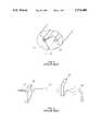
- Such a light diode bar 28includes a large number of parallel laser stripes 30 formed on a common GaAs substrate 31 that are arranged in groups 32 with gaps 34 between the groups.
- Each group 32laterally extends over about 200 82 m, and the entire light diode bar 28 laterally extends over about 1 cm and emits from a line 36 extending over nearly the same distance.
- the light emission pattern from such a light diode bar 28is illustrated isometrically in FIG. 4. In the vertical direction, the emission is diffraction limited from the approximately 1- ⁇ m high stripe and has a full vertical angle of 60°. On the other hand, the emissions from the groups 32 have a fun lateral angle of 10°, which still cannot be focused. Only with difficulty can such an emission pattern be impressed on a single optical fiber or into the end of a laser rod.
- High-power laser barshave rekindled interest in side-pumped lasers.
- the light diode bar 28has its line 36 of optical outputs parallel to the longitudinal axis 12 of the laser rod 10 with the pump light striking the entire side of the laser rod 10 along substantially the entire length of the rod 10.
- Diodes barsare characterized by source emission patterns which are long and thin, typically 1- ⁇ m wide and 1-cm long and producing up to 20 W of CW power.
- the high-intensity output of the light diode bar 28is directly coupled into the laser rod 10 along a substantial portion of its length. Nonetheless, the side-coupled, light diode bar configuration has several related problems.
- the pump lightis exponentially attenuated.
- Such an exponential pump light distributionpoorly matches the gaussian line shape of the desired TEM 00 optical mode propagating axially on the rod 10.
- uniformity of pump light in the rod 10varies inversely with the efficiency of absorption of that pump light in the rod 10.
- 4,908,832a related geometry in which the lasing light rather than the pump light is multiply reflected within the laser slab.
- these solutionsdo not address the thermal problem of high power lasers.
- these solutionsoften need to be matched to the characteristics of the diode lasers being used.
- diode barsexhibit a great number of variations, including the spacing of the laser stripes along the typical 1-cm length. Such variations arise for special applications, such as producing high peak power for short periods rather than a lower-level CW signal or to optimize the lifetime of the laser diode. Nonetheless, it would be desirable to have a common design for the different applications.
- an object of the inventionis to provide a high-power laser, optical amplifier, or other optically interacting device.
- Still another object of the inventionis to provide a solid-state laser pumped by a diode bar that is insensitive to variations in the construction and emission patterns of the laser diodes.
- the inventionmay be summarized as an optical engine in which a rod of optically active material is surrounded by a highly reflective layer except for a longitudinal slit through which a distributed light emitter, such as a laser diode, injects light into the optical cavity formed by the reflective layer around the optically active material.
- a distributed light emittersuch as a laser diode
- the cylindrical rodis in close thermal contact with a thermally conductive body with few or no voids therebetween or with a stream of cooling fluid.
- both the pump lightis trapped until it is nearly completely absorbed within the optically active material and further the temperature of the material is controlled.
- the inventionis particularly useful with solid-state lasers.
- FIG. 1is a cross-sectional view of a flashlamp laser of the prior art.
- FIG. 2is an isometric view of an end-pumped laser of the prior art.
- FIG. 3is a plan view of a laser bar of the prior art.
- FIG. 4is an isometric view of the optical emission pattern from the laser bar of FIG. 3.
- FIG. 5is an isometric view of a side-pumped laser of the prior art.
- FIG. 6is a cross-sectional view of a first major embodiment of a side-pumped light engine of the invention.
- FIG. 7is an isometric view of the inventive light engine of FIG. 6.
- FIG. 8is an isometric view of a plurality of symmetrically arranged optical engines providing a more uniform, higher-power pump power.
- FIG. 8Ais an isometric view of an embodiment similar to that of FIG. 8 in which the laser rod is continuous between multiple optical engines.
- FIG. 9is a schematic view of a laser incorporating the trigonal optical engine of FIG. 8.
- FIG. 10is a schematic view of a frequency-doubling laser similar to that of FIG. 9.
- FIG. 11is a cross-sectional view of a segmented cooling block enclosing a laser rod.
- FIG. 12is a cross-sectional view of a segmented cooling block enclosing a laser slab and pressed by a clamp.
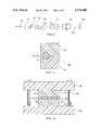
- FIG. 13is a cross-section view of a second major embodiment of the invention.
- FIG. 14is a plan view of a multi-stage, high-power optical engine of the invention.
- a first embodiment of an optical engine 38 of the inventionis illustrated in cross section in FIG. 6 and isometrically in FIG. 7.
- the laser rod 10is embedded in a cylindrical cavity in a solid block 40 of copper or other highly thermally conductive material and tightly thermally contacts the copper block 40.
- a surrounding surface 42 of the cylindrical cavityis coated with gold so as to reflect light with high efficiency.
- a linear slit 44is formed between the cylindrical cavity and the exterior of the copper block 40 and is sized to closely accommodate the 60° vertical emission angle from the stripe 36 of the photo-diode bar 28 with perhaps a few reflections within the slit 44.
- the diameter of the rod 10, that is, its dimension along the pump incidence direction,is preferably a small fraction, e.g.
- FIGS. 6 and 7allow effective thermal coupling by thermal conduction between the laser rod 10 and the copper block 40, which, besides having a large thermal mass, is mounted on a mount 46 that is heat sunk to cooling means, examples of which are chilled water, refrigeration systems, thermoelectric coolers, or finned radiators.
- cooling meansexamples of which are chilled water, refrigeration systems, thermoelectric coolers, or finned radiators.
- optical componentssuch as cylindrical lenses are inserted between the emission line 36 of the diode bar 28 and the entrance slit 44 to the optical cavity.
- optical componentscan be used to either transport the optical power to the slit 44 or to shape the emission pattern to alter the illumination of the solid-state laser material.
- the inventionprovides nearly complete optical absorption of the pump light, more uniform light absorption throughout the lasing medium, and efficient thermal control of lasing medium.
- the inventionis equally applicable to other cross sections of lasing medium, for example slabs, in which the rectangular sides of the slab are juxtaposed to highly reflecting solid surfaces and conductively heat sunk to them.
- the optical engine 38 of FIGS. 6 and 7can be included within a number of optical devices. Mirrors placed at both ends of the rod will form an optical cavity, and at high pump intensities, the device lases. If one of the mirrors is partially transmitting, lasing light exits the cavity through it. Alternatively, the optical engine can be included in a ring laser.
- the cavitymay also include any of the common intra-cavity elements, such as electro-optic or acousto-optic Q-switches, etalons, frequency-doubling crystals, prisms, mode-locking devices, polarizers, etc. These items are used to tailor the output of the laser, that is, to be pulsed, tuneable, spectrally modified, etc. Without the cavity end mirrors, the device operates as an optical amplifier.
- the optical engine of the inventionis compatible with these techniques, and some will be described later by example.
- a piece of copper alloy chosen for its high thermal conductivity and easy machinabilitywas cut to a block approximately 1 ⁇ 1 ⁇ 1.4 cm.
- a hole having a diameter of 1.2 mmwas then drilled to within 300 ⁇ m of the long side, and the drilled hole was then reamed and lapped.
- the slit 44was machined from the closest long side to the hole and had a width of 350 ⁇ m running along the entire length of the long side.
- the preliminary machiningwas performed to a tolerance of 1/10 mil (2.5 ⁇ m).
- the copper piecewas then gold coated to produce highly reflective surfaces within both the cylindrical cavity and the slit 44.
- a laser rod 10 of Nd-doped crystalline YAG having a diameter of 1.2 mm and a length of 1.5 cmwas then mounted into the drilled hole with a very thin layer of surrounding transparent adhesive of Sylgard 186 available from Dow Corning Corp. of Midland, Michigan.
- Sylgard 186available from Dow Corning Corp. of Midland, Michigan.
- the rodprotruded slightly beyond the ends of the optical cavity in the block.
- a glass cover glass with an anti-reflection coating and a thickness of 150 ⁇ mwas adhered to the side of the block 40 with the slit 44 in order to protect the diode laser and to enhance optical coupling.
- the laser bar 28, for example, Model SDL-3470-S available from SDL, Inc. emitting 20 W of optical power, and the copper block 40were fixed to a common mount 46 such that the line 36 of the laser bar 28 was aligned with the slit 44 of the copper block 40 and separated therefrom by about 200 ⁇ m.
- This optical enginewhen placed in the cavity described later with reference to FIG. 9, produced 4 W of optically polarized power in the TEM 00 mode.
- the 20-W CW laserwas replaced with a 100-W quasi-CW laser, Model SDL-3251-A1 from SDL, Inc.
- the laserproduces 4 mJ per pulse in a nearly diffraction-limited beam. Since both the quasi-CW and the CW diodes have a similar long, thin emitting region, the substitution of diodes is very straightforward. However, a concern is that the optical intensity from a quasi-CW diode bar is so high that the laser rod has sufficient gain to lase in an unintended direction, e.g., transversely across the rod.
- the cavity wall 44is coated with a dichroic coating that reflects at the pump frequency but not the lasing frequency. A dielectric stack provides such dichroic reflection.
- the cavity wall 44can be coated with a layer that is selectively absorbing at the laser frequency.
- each traverse of the 1.2-mm laser rod in conjunction with a 20-W CW diode bartypically produced a 1-dB small signal gain and several watts of saturated optical power while each traverse with a 100-W quasi-CW diode bar produced more than 4 dB of gain.
- the optical engine 38 of FIGS. 6 and 7provides substantially improved uniformity of pump radiation within the laser rod, thus contributing to the desired TEM 00 laser output mode. Nonetheless, the pump uniformity and mode purity can be further improved while simultaneously increasing the total optical power by arranging three such engines along a common optical path with the bar radiation axes trigonally distributed about the optical axis, i.e., at 0°, 120° and 240°
- the pump beamsare perpendicular to the optical axis but are arranged at equal azimuthal separations within a plane perpendicular to that axis.
- the jigs 58, 60, and 62are mounted on a common base that is thermally controlled, e.g., a thermoelectric cooler or the base is brazed to cooling water tubes, so as to maintain the laser rods 10 of all the engines 50, 52, and 54 at a desired operating temperature.
- the trigonal arrangementprovides a three-fold and possibly six-fold symmetry of pumping light within the laser medium.
- Other numbers of multiple optical enginescould beneficially be used, whether axially displaced as in FIG. 8 or at a same axial point.
- two optical engines azimuthally displaced by 90° in the axial arrangement of FIG. 8provides greatly increased uniformity without undue complexity.
- the trigonally arranged optical engine of FIG. 8was used in a high-power laser illustrated schematically in FIG. 9.
- Each 1.2-cm Nd:YAG rod 10 of the three engines 50, 52, and 54was optically pumped by a high-power optical diode (Model SDL-3470-S available from SDL, Inc.) that was 1-cm long and output 20 W of optical power.
- the three engineswere symmetrically oriented about the common optical axis 56 with separations between them of 1 cm.
- One mirror 64was coated for high reflectivity at 1.064 ⁇ m, and the other mirror 66 was coated for 85% reflectivity at 1.064 ⁇ m so as to output a laser beam 68.
- a high-index glass plate 67(Model SF-10 available from Schott) was inserted into the cavity at Brewster's angle to linearly polarize the output 68. This laser produced an output beam 68 that was highly diffraction-limited, highly polarized, and having 11 W of optical power.
- the laser of FIG. 9can be constructed with additional mirrors and incorporating additional intra-cavity elements 70, such as a Q-switch.
- additional intra-cavity elements 70such as a Q-switch.
- the embodiment of FIG. 9was constructed to produce a diffraction-limited beam by controlling the size of the fundamental mode, but, if it were made to be multi-moded, higher output power would be available.
- the extra element 70was an acousto-optic Q-switch.
- the resultant Q-switch laserproduced a pulsed output of 1.064- ⁇ m light from Nd: YAG .
- the mirrorswere reconfigured to provide a multi-folded, re-imaging cavity with a total length of 1.5 m, the laser produced 1.5-mJ, 70-ns pulses at a 1-kHz repetition rate. Shorter cavities produced shorter pulses. Since the Nd:YAG generated over 6 dB of round-trip optical gain, a very short cavity and an electro-optic Q-switch could be used to generate optical pulses of less than 10-ns pulse width.
- a KTP (potassium titanyl phosphate) crystal 72is placed at a 40- ⁇ m waist in a Z-shaped cavity formed by four mirrors 64, 74, 76, and 78.
- the non-linear optical characteristics of KTPcauses it to act as a frequency doubler in the presence of high-intensity light.
- Two mirrors 64 and 74are highly reflecting at 1.06 ⁇ m and have a radius of curvature (ROC) of 30 cm.
- a middle exit mirror 78 with a ROC of 10 cmis reflecting at 1.06 ⁇ m and is more than 95% transmitting at 0.53 ⁇ m.
- the end mirror 76is flat and highly reflecting at both 1.06 ⁇ m and 0.53 ⁇ m.
- This mirror 76reflects the 0.53 ⁇ m travelling in its direction back through the KTP crystal 72, combining it with other directions of 0.53 ⁇ m light.
- a waveplate 77is also placed within the cavity to improve output power and stability by decoupling the two polarization modes in the KTP crystal 72.
- a single, longer laser rod 10passes through the copper blocks 40 of all three optical engines 50, 52, and 54.
- the single rodreduces the number of coated surfaces and undesired reflections therefrom and reduces the alignment tolerances from rod to rod.
- the alignment of the incident pump radiation with the central axis of the rod, as is illustrated in FIG. 6,provides the uniformity of two-fold symmetry.
- the slit 44 and the pumping directioncan be aligned off the rod's optical axis, and the pump light will still be substantially confined within the cavity.
- the off-axis incidenceprevents immediate back reflection into the diode through the slit 44.
- a gold coatingprovides a nearly optimal reflective layer because of its highly reflective characteristics.
- beneficial effectscan be obtained with other highly reflective coatings, such as dielectric stack mirrors.
- highly reflectiveis meant a reflectivity facing the rod of more than 90% at the frequency (wavelength) of the pump light.
- the experimental examplesused a 350 ⁇ m slit on a 1.2-mm diameter rod so that 0.186 of the circumference is not reflective. Preferably no more than 25% of the circumference should be not highly reflective to obtain the best benefits of the invention.
- the geometry of the inventioncan provide at least 75% efficient absorption of the pumping light.
- Specular reflectionsare by nature non-uniform (although a large number of reflections inside a closed cavity will tend to randomize the intensity distribution).
- a nearly uniform distribution within the optical cavityis important for efficient generation of the gaussian-shaped fundamental mode of a stable resonator.
- a scattering componentcan be introduced both at the slit entrance and at internal reflecting wall of the optical cavity. Such scattering can be effected by the customary fine grinding of the surface of the barrel of the laser rod. The ground surface scatters the pump light both upon entrance into the laser rod within the optical cavity and upon each wall reflection.
- the reflective wall of the optically reflective and thermally conductive blockcan be textured to increase the amount of scattering.
- the lasing cavityproduce other than the circularly symmetric mode.
- the end faces of the laser rodare angled at Brewster's angle in order to expand the diameter of the fundamental mode in one dimension, as described by Wallace et al. in U.S. Pat. No. 5,103,457
- a circularly symmetric gaussian optical beam outside of the rodwill require an elliptically shaped beam (and pump light distribution) within the rod.
- the light distributiontends to an elliptical shape within the cavity, and the desired external circularity can be improved by aligning the angled end face such that the radiation direction of the diode bar lies parallel to the plane of the end face.
- the inventioncan use most of the known solid-state laser materials, but a number of specific materials are preferred. These materials include Nd:YAG, Nd:YLF, Tm:YAG, Nd:YVO 4 , Nd-doped glass, and Yb:YAG. Some of these materials will lase at more than one wavelength, and the invention is suited to both the dominant lasing wavelength and the secondaries, such as 1.064 ⁇ m and 1.319 ⁇ m in Nd:YAG. Experiments have demonstrated that with at least Nd:YAG, the dopant level can be less than the usual 1.0 atomic %. Successful results have been obtained with 0.6%, and even lower doping levels are usable with the invention. Thus, it is no longer necessary to sacrifice the crystalline quality of the lasing material in order to achieve satisfactorily high doping levels. Also, new materials for lasing can be considered which heretofore have not had sufficient absorption for efficient operation.
- the same inventive effectscan be achieved if the laser rod or slab, rather than the surrounding thermal sink, is coated to have a high reflectivity except along an axial slit that admits the pump radiation into the optical cavity.
- at least one of the longitudinal endsneeds to be at least partially transmissive depending on the application of the optical engine.
- FIGS. 6 and 7achieves good thermal contact with an adhesive between the laser rod and the thermally conductive, heat-sinking block.
- the material of the highly reflective and thermally conductive blockcan be chosen to be moderately soft so that the block can be pressed against the side of the rod and deform into intimate contact with the rod.
- a variety of standard clampscan be used and will not be described in detail. A notch in the block on the side opposite the slit will relieve stresses produced by the clamping. Of course, clamping eliminates the need for adhesive or other flowable thermal contacting material between the rod and cooling block.
- a cooling block assembly 80is divided into two or more body segments 82 and 84 which, when assembled together, form both an optical cavity for accommodating the laser rod 10 and the aperture 44 for entry of the pumping light into the optical cavity.
- the rod 10can be thermally sunk to the assembly 80 either by transparent adhesive or by a clamp exerting force in the illustrated vertical direction.
- a segmented cooling blockis useful also with a rectangular laser slab 90 sandwiched between two separately cooled rectangular blocks 92 and 94. The blocks 92 and 94 can be secured to the laser slab 90 with transparent adhesive.
- a clamp assemblyhas two jaw members 96 and 98 that are pressed together by rotating screws 10 passing through the upper jaw member 96 and threaded into the lower jaw member 98 to thereby force the segmented cooling blocks 92 and 94 into intimate contact with the laser slab 90.
- the clamp assemblyis presented only for relational purposes and could be substituted with other and possibly better clamping means.
- a slitted reflective surface and a fully reflective surfaceare preferably added to the slab's lateral sides 102 and 104 respectively. However, cooling of the sides 102 and 104 in this planar geometry is not so necessary.
- a second major embodiment of the inventionis shown in cross section in FIG. 13.
- a laser rod 120is suspended at the center within a transparent flow tube 122.
- the laser rod 120can be physically supported at ends beyond the optical interaction region or by fine supports within the interaction region that do not interfere with the pumping light.
- a cooling liquid 124flows axially through the flow tube 122 adjacent to the laser rod 120 throughout the optical interaction region so as to cool the rod.
- the cooling liquidcan be water or ethylene glycol, for example.
- a surface, preferably the outer surface, of the flow tube 122is coated with gold or other highly reflecting layer 125 so as to form an optical cavity therein.
- thin axial slits 126are formed in the gold or other highly reflecting layer 125 to admit pump light into the optical cavity.
- the slits 126are filled with an anti-reflection coating so as to optimize optical coupling.
- the extra size of the flow chamber and flow tubeallows multiple laser bars 28, four in the illustrated embodiment, to be circumferentially arranged along the same axial portion of the laser rod 120 in a symmetric arrangement.
- the heat removal from the laser material 120is also symmetric and efficient, allowing the invention to be scaled to kilowatts of laser output.
- a first exampleis a kilowatt-level multi-mode Nd:YAG laser in which the laser rod 120 is a standard rod that is 6.3 mm and 15 cm long and is mounted in a 9-mm ID quartz tube 122 with a wall thickness of 1.5 mm.
- the rod 120is held by collar within and at the ends of the quartz tube 122.
- Water cooling portsare laterally arranged at the tube ends similarly to the flow-tube method used to cool laser rods in many lasers pumped with arc lamps.
- the outside of the quartz tube 122is gold coated for high reflectivity at all angles for pump light at 808 nm except for four 350- ⁇ m slits 126. As illustrated further in plan view in FIG.
- a second example for a single assembly 128is a 50-W diffraction-limited laser.
- the laser rodis made from Nd:YAG to be 1.5 mm in diameter and 10 cm long.
- the tubehas an internal diameter of 3 mm and a 0.5-mm wall thickness, and it is made from either sapphire for additional strength or from the more usual glass or fused silica. Twelve 20-W diode bars arranged along two or three slits to illuminate the length of the rod will produce about 50 W of TEM 00 power.
- the smaller diameter roddoes not suffer loss of absorption efficiency because the pump light is trapped until it is absorbed.
- Lasers using the above described water coolingcan be incorporated into the previously described optical devices.
- Q-switchingcan provide very high power pulses while non-linear intra-cavity crystals can alter the output wavelength of the laser.
- the inventionthus provides a highly efficient laser or other optically active device that can be operated at very high powers.
- the geometryis amenable to producing a desirable circularly symmetric TEM 00 mode because of the small diameter laser rod that is possible, the uniformity of pump light within the rod, and the good thermal control.
- the designis flexible, it can be used with a variety of optical diode sources, it can be incorporated into many types of optical devices, and it can be scaled to yet higher powers.
Landscapes
- Physics & Mathematics (AREA)
- Electromagnetism (AREA)
- Engineering & Computer Science (AREA)
- Plasma & Fusion (AREA)
- Optics & Photonics (AREA)
- Lasers (AREA)
Abstract
Description
Claims (10)
Priority Applications (1)
| Application Number | Priority Date | Filing Date | Title |
|---|---|---|---|
| US08/268,781US5774488A (en) | 1994-06-30 | 1994-06-30 | Solid-state laser with trapped pump light |
Applications Claiming Priority (1)
| Application Number | Priority Date | Filing Date | Title |
|---|---|---|---|
| US08/268,781US5774488A (en) | 1994-06-30 | 1994-06-30 | Solid-state laser with trapped pump light |
Publications (1)
| Publication Number | Publication Date |
|---|---|
| US5774488Atrue US5774488A (en) | 1998-06-30 |
Family
ID=23024449
Family Applications (1)
| Application Number | Title | Priority Date | Filing Date |
|---|---|---|---|
| US08/268,781Expired - LifetimeUS5774488A (en) | 1994-06-30 | 1994-06-30 | Solid-state laser with trapped pump light |
Country Status (1)
| Country | Link |
|---|---|
| US (1) | US5774488A (en) |
Cited By (38)
| Publication number | Priority date | Publication date | Assignee | Title |
|---|---|---|---|---|
| US6282217B1 (en)* | 1998-09-04 | 2001-08-28 | Kabushiki Kaisha Toshiba | Solid-state laser device |
| US6347101B1 (en) | 1998-04-16 | 2002-02-12 | 3D Systems, Inc. | Laser with absorption optimized pumping of a gain medium |
| US6433306B1 (en)* | 1997-02-19 | 2002-08-13 | Jds Uniphase Corp. | Semiconductor laser high power amplifier system for materials processing |
| US20030058914A1 (en)* | 2000-12-19 | 2003-03-27 | Claus-Rudiger Haas | Optically pumped solid-state laser |
| US20030099267A1 (en)* | 2000-12-06 | 2003-05-29 | Petra Hennig | Diode laser arrangement with several diode laser rows |
| WO2003052889A1 (en)* | 2001-12-18 | 2003-06-26 | Ibl Industrial Broad-Spectrum Laser Ag | Pump arrangement for transversally pumping an active medium |
| US6608852B2 (en)* | 2000-08-25 | 2003-08-19 | Lameda Physik Ag | Gain module for diode-pumped solid state laser and amplifier |
| US20030161364A1 (en)* | 2001-11-21 | 2003-08-28 | General Atomics | Laser containing a slurry |
| US6614584B1 (en) | 2000-02-25 | 2003-09-02 | Lambda Physik Ag | Laser frequency converter with automatic phase matching adjustment |
| WO2003017438A3 (en)* | 2001-08-17 | 2003-11-06 | Textron Systems Corp | Cooling of high power laser systems |
| US20040028108A1 (en)* | 2002-02-07 | 2004-02-12 | Govorkov Sergei V. | Solid-state diode pumped laser employing oscillator-amplifier |
| WO2003009440A3 (en)* | 2001-07-20 | 2004-02-12 | Powerlase Ltd | Laser apparatus |
| US6704341B1 (en)* | 1999-11-19 | 2004-03-09 | The Regents Of The University Of California | Diode-pumped laser with improved pumping system |
| US6721087B2 (en) | 2001-12-13 | 2004-04-13 | Intel Corporation | Optical amplifier with distributed evanescently-coupled pump |
| US6778319B2 (en) | 2001-09-10 | 2004-08-17 | Np Photonics, Inc. | Side-pumped multi-port optical amplifier and method of manufacture using fiber drawing technologies |
| US6785315B1 (en)* | 2001-09-24 | 2004-08-31 | Northrop Grumman Corporation | Mobile tactical high energy laser weapon system and method for generating a high energy laser beam |
| US20050058165A1 (en)* | 2003-09-12 | 2005-03-17 | Lightwave Electronics Corporation | Laser having <100>-oriented crystal gain medium |
| US6888668B2 (en) | 2001-12-13 | 2005-05-03 | Intel Corporation | Optical amplifier with multiple wavelength pump |
| US20050100071A1 (en)* | 2000-08-31 | 2005-05-12 | Taylor Alan G. | Electromagnetic radiation generation using a laser produced plasma |
| US20050259705A1 (en)* | 2004-05-20 | 2005-11-24 | Kabushiki Kaisha Topcon | Laser oscillation device |
| EP1226636A4 (en)* | 1999-10-15 | 2006-01-11 | Jmar Res Inc | Beam correcting laser amplifier |
| US20060133433A1 (en)* | 2004-12-22 | 2006-06-22 | Alexander Jason I | Efficient chamber pumped fiber laser and amplifier |
| US7082149B1 (en) | 2003-06-24 | 2006-07-25 | Photonics Industries Int'l | High power diode side pumped solid state laser |
| US7130111B2 (en)* | 2001-12-13 | 2006-10-31 | Intel Corporation | Optical amplifier with transverse pump |
| US20070230884A1 (en)* | 2006-03-21 | 2007-10-04 | Aculight Corporation | Method and apparatus for optical delivery fiber having cladding with absorbing regions |
| US7346092B1 (en) | 2005-12-16 | 2008-03-18 | Photonics Industries Int'l. | Diode side pumped high pulse energy Nd:YLF lasers |
| US20080089380A1 (en)* | 2006-09-28 | 2008-04-17 | Osram Opto Semiconductors Gmbh | Laser arrangement and semiconductor laser for optically pumping a laser |
| US7408971B2 (en) | 2006-02-28 | 2008-08-05 | Quantronix Corporation | Longitudinally pumped solid state laser and methods of making and using |
| US20090304039A1 (en)* | 2006-04-13 | 2009-12-10 | Osram Opto Semiconductors Gmbh | Optoelectronic semiconductor element |
| US20090304040A1 (en)* | 2005-12-28 | 2009-12-10 | Ram Oron | Diode-pumped cavity |
| FR2936109A1 (en)* | 2008-09-17 | 2010-03-19 | Thales Sa | OPTICAL PUMPING STRUCTURE. |
| US8089689B1 (en) | 2006-11-30 | 2012-01-03 | Lockheed Martin Corporation | Apparatus and method for optical gain fiber having segments of differing core sizes |
| CN102545034A (en)* | 2011-04-21 | 2012-07-04 | 北京国科世纪激光技术有限公司 | Lateral pump module of semiconductor module |
| GB2506402A (en)* | 2012-09-28 | 2014-04-02 | Thales Holdings Uk Plc | Side pumped laser |
| WO2015117727A1 (en)* | 2014-02-05 | 2015-08-13 | Pantec Biosolutions Ag | Assembly comprising an amplifying laser material and a cooling unit |
| RU2592056C1 (en)* | 2015-01-21 | 2016-07-20 | Российская Федерация, от имени которой выступает Государственная корпорация по атомной энергии "Росатом" (Госкорпорация "Росатом") | Solid-state laser emitter without fluid cooling with thermal stabilisation of diode pumping |
| CN111064068A (en)* | 2018-10-16 | 2020-04-24 | 朗美通经营有限责任公司 | Amplifier assembly |
| EP4181332A4 (en)* | 2020-09-04 | 2024-08-21 | Hamamatsu Photonics K.K. | LASER DEVICE AND METHOD FOR MANUFACTURING LASER DEVICE |
Citations (16)
| Publication number | Priority date | Publication date | Assignee | Title |
|---|---|---|---|---|
| US3683296A (en)* | 1970-10-13 | 1972-08-08 | Texas Instruments Inc | High efficiency laser cavity |
| US3684980A (en)* | 1970-10-13 | 1972-08-15 | Texas Instruments Inc | High effective absorption coefficient solid state laser rods |
| US3821663A (en)* | 1973-01-15 | 1974-06-28 | Motorola Inc | Integral reflecting cavity semiconductor pumped laser |
| US4594716A (en)* | 1981-11-09 | 1986-06-10 | Gte Government Systems Corporation | Conduction cooled solid state laser |
| JPH0254588A (en)* | 1988-08-18 | 1990-02-23 | Mitsubishi Electric Corp | solid state laser device |
| US4908832A (en)* | 1985-05-01 | 1990-03-13 | Spectra-Physics, Inc. | High efficiency mode-matched solid-state laser with transverse pumping |
| US4916712A (en)* | 1989-07-27 | 1990-04-10 | Mcdonnell Douglas Corporation | Optically pumped slab laser |
| US4949346A (en)* | 1989-08-14 | 1990-08-14 | Allied-Signal Inc. | Conductively cooled, diode-pumped solid-state slab laser |
| US4969155A (en)* | 1989-10-10 | 1990-11-06 | Hughes Aircraft Company | Integrating laser diode pumped laser apparatus |
| US5033058A (en)* | 1989-01-04 | 1991-07-16 | Laserdot | Rod laser with optical pumping from a source having a narrow emitting area |
| US5048044A (en)* | 1988-12-22 | 1991-09-10 | Lumonics, Ltd. | Optically pumped lasers |
| US5103457A (en)* | 1990-02-07 | 1992-04-07 | Lightwave Electronics Corporation | Elliptical mode cavities for solid-state lasers pumped by laser diodes |
| US5172388A (en)* | 1991-07-23 | 1992-12-15 | International Business Machines Corporation | Method and apparatus for an increased pulse repetition rate for a CW pumped laser |
| US5243615A (en)* | 1991-11-20 | 1993-09-07 | Laserscope | High-powered intracavity non-linear optic laser |
| JPH05335662A (en)* | 1992-05-27 | 1993-12-17 | Hoya Corp | Solid-state laser device |
| US5317585A (en)* | 1992-08-17 | 1994-05-31 | Hughes Aircraft Company | Laser reflecting cavity with ASE suppression and heat removal |
- 1994
- 1994-06-30USUS08/268,781patent/US5774488A/ennot_activeExpired - Lifetime
Patent Citations (16)
| Publication number | Priority date | Publication date | Assignee | Title |
|---|---|---|---|---|
| US3684980A (en)* | 1970-10-13 | 1972-08-15 | Texas Instruments Inc | High effective absorption coefficient solid state laser rods |
| US3683296A (en)* | 1970-10-13 | 1972-08-08 | Texas Instruments Inc | High efficiency laser cavity |
| US3821663A (en)* | 1973-01-15 | 1974-06-28 | Motorola Inc | Integral reflecting cavity semiconductor pumped laser |
| US4594716A (en)* | 1981-11-09 | 1986-06-10 | Gte Government Systems Corporation | Conduction cooled solid state laser |
| US4908832A (en)* | 1985-05-01 | 1990-03-13 | Spectra-Physics, Inc. | High efficiency mode-matched solid-state laser with transverse pumping |
| JPH0254588A (en)* | 1988-08-18 | 1990-02-23 | Mitsubishi Electric Corp | solid state laser device |
| US5048044A (en)* | 1988-12-22 | 1991-09-10 | Lumonics, Ltd. | Optically pumped lasers |
| US5033058A (en)* | 1989-01-04 | 1991-07-16 | Laserdot | Rod laser with optical pumping from a source having a narrow emitting area |
| US4916712A (en)* | 1989-07-27 | 1990-04-10 | Mcdonnell Douglas Corporation | Optically pumped slab laser |
| US4949346A (en)* | 1989-08-14 | 1990-08-14 | Allied-Signal Inc. | Conductively cooled, diode-pumped solid-state slab laser |
| US4969155A (en)* | 1989-10-10 | 1990-11-06 | Hughes Aircraft Company | Integrating laser diode pumped laser apparatus |
| US5103457A (en)* | 1990-02-07 | 1992-04-07 | Lightwave Electronics Corporation | Elliptical mode cavities for solid-state lasers pumped by laser diodes |
| US5172388A (en)* | 1991-07-23 | 1992-12-15 | International Business Machines Corporation | Method and apparatus for an increased pulse repetition rate for a CW pumped laser |
| US5243615A (en)* | 1991-11-20 | 1993-09-07 | Laserscope | High-powered intracavity non-linear optic laser |
| JPH05335662A (en)* | 1992-05-27 | 1993-12-17 | Hoya Corp | Solid-state laser device |
| US5317585A (en)* | 1992-08-17 | 1994-05-31 | Hughes Aircraft Company | Laser reflecting cavity with ASE suppression and heat removal |
Non-Patent Citations (10)
| Title |
|---|
| Ajer et al., "Efficient diode-laser side-pumped TEM00 -mode Nd:YAG laser," Optics Letters, vol. 17, Dec. 1992, pp. 1785-1787. |
| Ajer et al., Efficient diode laser side pumped TEM 00 mode Nd:YAG laser, Optics Letters, vol. 17, Dec. 1992, pp. 1785 1787.* |
| Hanson et al., "Laser Diode side pumping of neodymium laser rods," Applied Optics, vol. 27, Jan. 1988. pp.80-83. |
| Hanson et al., Laser Diode side pumping of neodymium laser rods, Applied Optics, vol. 27, Jan. 1988. pp.80 83.* |
| Marshall et al., "Highly efficient TEM00 operation of transversely diode-pumped Nd:YAG lasers," Optics Letters, vol. 17, Feb. 1992, pp. 186-188. |
| Marshall et al., Highly efficient TEM 00 operation of transversely diode pumped Nd:YAG lasers, Optics Letters, vol. 17, Feb. 1992, pp. 186 188.* |
| Oka et al., "Stable intracavity doubling of orthogonal linearly polarized modes in diode-pumped Nd:YAG laser," Optics Letters, vol. 13, Oct. 1988, pp. 805-807. |
| Oka et al., Stable intracavity doubling of orthogonal linearly polarized modes in diode pumped Nd:YAG laser, Optics Letters, vol. 13, Oct. 1988, pp. 805 807.* |
| Welford et al., "Efficient TEM00 -mode operation of a laser-diode side-pumped Nd:YAG laser," Optics Letters, vol. 16, Dec. 1991, pp. 1850-1852. |
| Welford et al., Efficient TEM 00 mode operation of a laser diode side pumped Nd:YAG laser, Optics Letters, vol. 16, Dec. 1991, pp. 1850 1852.* |
Cited By (66)
| Publication number | Priority date | Publication date | Assignee | Title |
|---|---|---|---|---|
| US6433306B1 (en)* | 1997-02-19 | 2002-08-13 | Jds Uniphase Corp. | Semiconductor laser high power amplifier system for materials processing |
| US6347101B1 (en) | 1998-04-16 | 2002-02-12 | 3D Systems, Inc. | Laser with absorption optimized pumping of a gain medium |
| US6282217B1 (en)* | 1998-09-04 | 2001-08-28 | Kabushiki Kaisha Toshiba | Solid-state laser device |
| EP1226636A4 (en)* | 1999-10-15 | 2006-01-11 | Jmar Res Inc | Beam correcting laser amplifier |
| US6704341B1 (en)* | 1999-11-19 | 2004-03-09 | The Regents Of The University Of California | Diode-pumped laser with improved pumping system |
| US6614584B1 (en) | 2000-02-25 | 2003-09-02 | Lambda Physik Ag | Laser frequency converter with automatic phase matching adjustment |
| US6608852B2 (en)* | 2000-08-25 | 2003-08-19 | Lameda Physik Ag | Gain module for diode-pumped solid state laser and amplifier |
| US6956885B2 (en) | 2000-08-31 | 2005-10-18 | Powerlase Limited | Electromagnetic radiation generation using a laser produced plasma |
| US20050100071A1 (en)* | 2000-08-31 | 2005-05-12 | Taylor Alan G. | Electromagnetic radiation generation using a laser produced plasma |
| US6898222B2 (en)* | 2000-12-06 | 2005-05-24 | Jenoptik Laserdiode Gmbh | Diode laser arrangement with a plurality of diode laser arrays |
| US20030099267A1 (en)* | 2000-12-06 | 2003-05-29 | Petra Hennig | Diode laser arrangement with several diode laser rows |
| US20030058914A1 (en)* | 2000-12-19 | 2003-03-27 | Claus-Rudiger Haas | Optically pumped solid-state laser |
| US20040247003A1 (en)* | 2001-07-20 | 2004-12-09 | Mercer Ian Peter | Laser apparatus |
| WO2003009440A3 (en)* | 2001-07-20 | 2004-02-12 | Powerlase Ltd | Laser apparatus |
| WO2003009433A3 (en)* | 2001-07-20 | 2004-02-26 | Powerlase Ltd | Laser apparatus |
| WO2003017438A3 (en)* | 2001-08-17 | 2003-11-06 | Textron Systems Corp | Cooling of high power laser systems |
| US6667999B2 (en) | 2001-08-17 | 2003-12-23 | Textron Corporation | Cooling of high power laser systems |
| US6778319B2 (en) | 2001-09-10 | 2004-08-17 | Np Photonics, Inc. | Side-pumped multi-port optical amplifier and method of manufacture using fiber drawing technologies |
| US6785315B1 (en)* | 2001-09-24 | 2004-08-31 | Northrop Grumman Corporation | Mobile tactical high energy laser weapon system and method for generating a high energy laser beam |
| US6937629B2 (en) | 2001-11-21 | 2005-08-30 | General Atomics | Laser containing a distributed gain medium |
| US7103078B2 (en) | 2001-11-21 | 2006-09-05 | General Atomics | Laser containing a distributed gain medium |
| US20070002921A1 (en)* | 2001-11-21 | 2007-01-04 | General Atomics | Laser Containing a Distributed Gain Medium |
| US20030161365A1 (en)* | 2001-11-21 | 2003-08-28 | General Atomics | Laser containing a distributed gain medium |
| US20030161364A1 (en)* | 2001-11-21 | 2003-08-28 | General Atomics | Laser containing a slurry |
| US7366211B2 (en) | 2001-11-21 | 2008-04-29 | General Atomics | Laser containing a distributed gain medium |
| US7130111B2 (en)* | 2001-12-13 | 2006-10-31 | Intel Corporation | Optical amplifier with transverse pump |
| US6721087B2 (en) | 2001-12-13 | 2004-04-13 | Intel Corporation | Optical amplifier with distributed evanescently-coupled pump |
| US6888668B2 (en) | 2001-12-13 | 2005-05-03 | Intel Corporation | Optical amplifier with multiple wavelength pump |
| WO2003052889A1 (en)* | 2001-12-18 | 2003-06-26 | Ibl Industrial Broad-Spectrum Laser Ag | Pump arrangement for transversally pumping an active medium |
| US20050129080A1 (en)* | 2001-12-18 | 2005-06-16 | Frank Massmann | Pump arrangement for transversally pumping an active medium |
| US7266138B2 (en) | 2001-12-18 | 2007-09-04 | Ibl Industrial Broad-Spectrum Laser Ag | Pump arrangement for transversally pumping an active medium |
| US20040028108A1 (en)* | 2002-02-07 | 2004-02-12 | Govorkov Sergei V. | Solid-state diode pumped laser employing oscillator-amplifier |
| WO2003067721A3 (en)* | 2002-02-07 | 2004-03-04 | Lambda Physik Ag | Solid-state diode pumped laser employing oscillator-amplifier |
| US7082149B1 (en) | 2003-06-24 | 2006-07-25 | Photonics Industries Int'l | High power diode side pumped solid state laser |
| US20050058165A1 (en)* | 2003-09-12 | 2005-03-17 | Lightwave Electronics Corporation | Laser having <100>-oriented crystal gain medium |
| US20050259705A1 (en)* | 2004-05-20 | 2005-11-24 | Kabushiki Kaisha Topcon | Laser oscillation device |
| US20060133433A1 (en)* | 2004-12-22 | 2006-06-22 | Alexander Jason I | Efficient chamber pumped fiber laser and amplifier |
| US7346092B1 (en) | 2005-12-16 | 2008-03-18 | Photonics Industries Int'l. | Diode side pumped high pulse energy Nd:YLF lasers |
| US8270443B2 (en) | 2005-12-28 | 2012-09-18 | Israel Aerospace Industries Ltd. | Diode-pumped cavity |
| US20090304040A1 (en)* | 2005-12-28 | 2009-12-10 | Ram Oron | Diode-pumped cavity |
| US7408971B2 (en) | 2006-02-28 | 2008-08-05 | Quantronix Corporation | Longitudinally pumped solid state laser and methods of making and using |
| US20070230884A1 (en)* | 2006-03-21 | 2007-10-04 | Aculight Corporation | Method and apparatus for optical delivery fiber having cladding with absorbing regions |
| US7835608B2 (en)* | 2006-03-21 | 2010-11-16 | Lockheed Martin Corporation | Method and apparatus for optical delivery fiber having cladding with absorbing regions |
| US8351479B2 (en)* | 2006-04-13 | 2013-01-08 | Osram Opto Semiconductors Gmbh | Optoelectronic semiconductor element |
| US20090304039A1 (en)* | 2006-04-13 | 2009-12-10 | Osram Opto Semiconductors Gmbh | Optoelectronic semiconductor element |
| US20080089380A1 (en)* | 2006-09-28 | 2008-04-17 | Osram Opto Semiconductors Gmbh | Laser arrangement and semiconductor laser for optically pumping a laser |
| US8705166B1 (en) | 2006-11-30 | 2014-04-22 | Lockheed Martin Corporation | Optical gain fiber having tapered segments of differing core sizes and associated method |
| US8089689B1 (en) | 2006-11-30 | 2012-01-03 | Lockheed Martin Corporation | Apparatus and method for optical gain fiber having segments of differing core sizes |
| US8345348B1 (en) | 2006-11-30 | 2013-01-01 | Lockheed Martin Corporation | Method and optical gain fiber having segments of differing core sizes |
| US8199399B1 (en) | 2006-11-30 | 2012-06-12 | Lockheed Martin Corporation | Optical gain fiber having segments of differing core sizes and associated method |
| US20110235662A1 (en)* | 2008-09-17 | 2011-09-29 | Thales | Optical pumping structure |
| JP2012503302A (en)* | 2008-09-17 | 2012-02-02 | テールズ | Optical pumping structure |
| WO2010031606A1 (en)* | 2008-09-17 | 2010-03-25 | Thales | Optical pumping structure |
| US9343866B2 (en) | 2008-09-17 | 2016-05-17 | Thales | Optical pumping structure |
| FR2936109A1 (en)* | 2008-09-17 | 2010-03-19 | Thales Sa | OPTICAL PUMPING STRUCTURE. |
| CN102545034A (en)* | 2011-04-21 | 2012-07-04 | 北京国科世纪激光技术有限公司 | Lateral pump module of semiconductor module |
| GB2506402B (en)* | 2012-09-28 | 2016-02-17 | Thales Holdings Uk Plc | Side pumped laser |
| GB2506402A (en)* | 2012-09-28 | 2014-04-02 | Thales Holdings Uk Plc | Side pumped laser |
| WO2015117727A1 (en)* | 2014-02-05 | 2015-08-13 | Pantec Biosolutions Ag | Assembly comprising an amplifying laser material and a cooling unit |
| RU2592056C1 (en)* | 2015-01-21 | 2016-07-20 | Российская Федерация, от имени которой выступает Государственная корпорация по атомной энергии "Росатом" (Госкорпорация "Росатом") | Solid-state laser emitter without fluid cooling with thermal stabilisation of diode pumping |
| CN111064068A (en)* | 2018-10-16 | 2020-04-24 | 朗美通经营有限责任公司 | Amplifier assembly |
| US11349274B2 (en)* | 2018-10-16 | 2022-05-31 | Lumentum Operations Llc | Amplifier assembly |
| US20220278496A1 (en)* | 2018-10-16 | 2022-09-01 | Lumentum Operations Llc | Amplifier assembly |
| US11894651B2 (en)* | 2018-10-16 | 2024-02-06 | Lumentum Operations Llc | Amplifier assembly |
| CN111064068B (en)* | 2018-10-16 | 2024-07-19 | 朗美通经营有限责任公司 | Amplifier assembly |
| EP4181332A4 (en)* | 2020-09-04 | 2024-08-21 | Hamamatsu Photonics K.K. | LASER DEVICE AND METHOD FOR MANUFACTURING LASER DEVICE |
Similar Documents
| Publication | Publication Date | Title |
|---|---|---|
| US5774488A (en) | Solid-state laser with trapped pump light | |
| JP4377232B2 (en) | Laser with distributed gain medium | |
| US5182759A (en) | Apparatus and method for pumping of a weakly absorbing lasant material | |
| US6625193B2 (en) | Side-pumped active mirror solid-state laser for high-average power | |
| US7535633B2 (en) | Laser amplifiers with high gain and small thermal aberrations | |
| EP1500174B1 (en) | Laser cavity pumping method and laser system thereof | |
| US5867324A (en) | Side-pumped laser with shaped laser beam | |
| US6847673B2 (en) | Solid state laser disk amplifer architecture: the normal-incidence stack | |
| WO2010145855A1 (en) | Monolithic, side pumped solid-state laser and method for operating the same | |
| US5774489A (en) | Transversely pumped solid state laser | |
| CN113889831A (en) | Compact type strip pulse laser | |
| US5577060A (en) | Diode pumped laser using crystals with strong thermal focussing | |
| WO2002073759A1 (en) | Diode-pumped solid-state laser in a polyhedronal geometry | |
| JP2004296671A (en) | Solid state laser device | |
| KR20180023132A (en) | Slab solid laser amplifier | |
| CN115459040A (en) | Disc laser | |
| EP0457523A2 (en) | Apparatus and method for pumping of a weakly absorbing lasant material | |
| CN113889832A (en) | Passive Q-switched laser of pumping | |
| KR100348998B1 (en) | Solid-state laser module with diffusive cavity pumped by radially positioned laser diodes having line shape emitters | |
| EP1788672A2 (en) | Laser containing a distributed gain medium | |
| US20060285571A1 (en) | Diode-pumped, solid-state laser with chip-shaped laser medium and heat sink | |
| CN119542896A (en) | A single longitudinal mode laser based on LED pumping | |
| Graf et al. | Novel optical resonators and thermal lensing | |
| Camargo et al. | Compact, diode side-pumped Nd: YVO4 cw laser with 74% slope efficiency and 22 W output power | |
| Oh | Power Scaling of High Power Solid State Lasers. |
Legal Events
| Date | Code | Title | Description |
|---|---|---|---|
| AS | Assignment | Owner name:LIGHTWAVE ELECTRONICS CORPORATION, CALIFORNIA Free format text:ASSIGNMENT OF ASSIGNORS INTEREST;ASSIGNOR:KMETEC, JEFFREY D.;REEL/FRAME:007065/0979 Effective date:19940630 | |
| STCF | Information on status: patent grant | Free format text:PATENTED CASE | |
| FPAY | Fee payment | Year of fee payment:4 | |
| FEPP | Fee payment procedure | Free format text:PAT HOLDER NO LONGER CLAIMS SMALL ENTITY STATUS, ENTITY STATUS SET TO UNDISCOUNTED (ORIGINAL EVENT CODE: STOL); ENTITY STATUS OF PATENT OWNER: LARGE ENTITY | |
| FEPP | Fee payment procedure | Free format text:PAYER NUMBER DE-ASSIGNED (ORIGINAL EVENT CODE: RMPN); ENTITY STATUS OF PATENT OWNER: LARGE ENTITY Free format text:PAYOR NUMBER ASSIGNED (ORIGINAL EVENT CODE: ASPN); ENTITY STATUS OF PATENT OWNER: LARGE ENTITY | |
| AS | Assignment | Owner name:JDS UNIPHASE CORPORATION, CALIFORNIA Free format text:ASSIGNMENT OF ASSIGNORS INTEREST;ASSIGNOR:LIGHTWAVE ELECTRONICS CORPORATION;REEL/FRAME:016345/0054 Effective date:20050729 | |
| FPAY | Fee payment | Year of fee payment:8 | |
| FPAY | Fee payment | Year of fee payment:12 | |
| AS | Assignment | Owner name:LUMENTUM OPERATIONS LLC, CALIFORNIA Free format text:ASSIGNMENT OF ASSIGNORS INTEREST;ASSIGNOR:JDS UNIPHASE CORPORATION;REEL/FRAME:036420/0340 Effective date:20150731 | |
| AS | Assignment | Owner name:LUMENTUM OPERATIONS LLC, CALIFORNIA Free format text:CORRECTIVE ASSIGNMENT TO CORRECT INCORRECT PATENTS 7,868,247 AND 6,476,312 ON PAGE A-A33 PREVIOUSLY RECORDED ON REEL 036420 FRAME 0340. ASSIGNOR(S) HEREBY CONFIRMS THE ASSIGNMENT;ASSIGNOR:JDS UNIPHASE CORPORATION;REEL/FRAME:037562/0513 Effective date:20150731 Owner name:LUMENTUM OPERATIONS LLC, CALIFORNIA Free format text:CORRECTIVE ASSIGNMENT TO CORRECT THE PATENTS LISTED ON PAGE A-A33 PREVIOUSLY RECORDED ON REEL 036420 FRAME 0340. ASSIGNOR(S) HEREBY CONFIRMS THE PATENT NUMBERS 7,868,247 AND 6,476,312 WERE LISTED IN ERROR AND SHOULD BE REMOVED;ASSIGNOR:JDS UNIPHASE CORPORATION;REEL/FRAME:037562/0513 Effective date:20150731 | |
| AS | Assignment | Owner name:LUMENTUM OPERATIONS LLC, CALIFORNIA Free format text:CORRECTIVE ASSIGNMENT TO CORRECT THE PATENTS LISTED ON PAGE A-A33 PATENT NUMBERS 7,868,247 AND 6,476,312 WERE LISTED IN ERROR AND SHOULD BE REMOVED. PREVIOUSLY RECORDED ON REEL 036420 FRAME 0340. ASSIGNOR(S) HEREBY CONFIRMS THE ASSIGNMENT;ASSIGNOR:JDS UNIPHASE CORPORATION;REEL/FRAME:037627/0641 Effective date:20150731 Owner name:LUMENTUM OPERATIONS LLC, CALIFORNIA Free format text:CORRECTIVE ASSIGNMENT TO CORRECT PATENTS 7,868,247 AND 6,476,312 LISTED ON PAGE A-A33 PREVIOUSLY RECORDED ON REEL 036420 FRAME 0340. ASSIGNOR(S) HEREBY CONFIRMS THE ASSIGNMENT;ASSIGNOR:JDS UNIPHASE CORPORATION;REEL/FRAME:037627/0641 Effective date:20150731 | |
| FEPP | Fee payment procedure | Free format text:PAYER NUMBER DE-ASSIGNED (ORIGINAL EVENT CODE: RMPN); ENTITY STATUS OF PATENT OWNER: LARGE ENTITY Free format text:PAYOR NUMBER ASSIGNED (ORIGINAL EVENT CODE: ASPN); ENTITY STATUS OF PATENT OWNER: LARGE ENTITY |