US5774487A - Filamented multi-wavelength vertical-cavity surface emitting laser - Google Patents
Filamented multi-wavelength vertical-cavity surface emitting laserDownload PDFInfo
- Publication number
- US5774487A US5774487AUS08/734,403US73440396AUS5774487AUS 5774487 AUS5774487 AUS 5774487AUS 73440396 AUS73440396 AUS 73440396AUS 5774487 AUS5774487 AUS 5774487A
- Authority
- US
- United States
- Prior art keywords
- mirror
- vcsel
- discrete locations
- region
- vcsel according
- Prior art date
- Legal status (The legal status is an assumption and is not a legal conclusion. Google has not performed a legal analysis and makes no representation as to the accuracy of the status listed.)
- Expired - Lifetime
Links
- 239000000463materialSubstances0.000claimsdescription12
- 239000002019doping agentSubstances0.000claimsdescription9
- 239000002184metalSubstances0.000claimsdescription8
- 229920006395saturated elastomerPolymers0.000claims2
- 238000002347injectionMethods0.000abstractdescription11
- 239000007924injectionSubstances0.000abstractdescription11
- 239000000835fiberSubstances0.000abstractdescription4
- 238000003384imaging methodMethods0.000abstractdescription4
- 238000005253claddingMethods0.000abstractdescription3
- 238000012935AveragingMethods0.000abstractdescription2
- 239000010410layerSubstances0.000description29
- 230000003287optical effectEffects0.000description16
- 238000001228spectrumMethods0.000description9
- 229910000980Aluminium gallium arsenideInorganic materials0.000description5
- 229910001218Gallium arsenideInorganic materials0.000description5
- 239000004065semiconductorSubstances0.000description5
- 238000003491arrayMethods0.000description4
- 230000000694effectsEffects0.000description4
- 125000006850spacer groupChemical group0.000description4
- 238000004891communicationMethods0.000description3
- 238000010586diagramMethods0.000description3
- 238000005516engineering processMethods0.000description3
- 238000004519manufacturing processMethods0.000description3
- 238000005259measurementMethods0.000description3
- 239000000758substrateSubstances0.000description3
- 230000002238attenuated effectEffects0.000description2
- 230000008859changeEffects0.000description2
- 239000013307optical fiberSubstances0.000description2
- 230000004044responseEffects0.000description2
- 238000000927vapour-phase epitaxyMethods0.000description2
- 230000004075alterationEffects0.000description1
- PNEYBMLMFCGWSK-UHFFFAOYSA-Naluminium oxideInorganic materials[O-2].[O-2].[O-2].[Al+3].[Al+3]PNEYBMLMFCGWSK-UHFFFAOYSA-N0.000description1
- 238000013459approachMethods0.000description1
- 239000002800charge carrierSubstances0.000description1
- 230000001427coherent effectEffects0.000description1
- 230000008878couplingEffects0.000description1
- 238000010168coupling processMethods0.000description1
- 238000005859coupling reactionMethods0.000description1
- 230000007423decreaseEffects0.000description1
- 239000003989dielectric materialSubstances0.000description1
- 239000006185dispersionSubstances0.000description1
- 238000005530etchingMethods0.000description1
- 230000010354integrationEffects0.000description1
- 239000007769metal materialSubstances0.000description1
- 238000000034methodMethods0.000description1
- 238000001451molecular beam epitaxyMethods0.000description1
- 238000000059patterningMethods0.000description1
- 238000012545processingMethods0.000description1
- 239000002356single layerSubstances0.000description1
- 238000012360testing methodMethods0.000description1
Images


Classifications
- H—ELECTRICITY
- H01—ELECTRIC ELEMENTS
- H01S—DEVICES USING THE PROCESS OF LIGHT AMPLIFICATION BY STIMULATED EMISSION OF RADIATION [LASER] TO AMPLIFY OR GENERATE LIGHT; DEVICES USING STIMULATED EMISSION OF ELECTROMAGNETIC RADIATION IN WAVE RANGES OTHER THAN OPTICAL
- H01S5/00—Semiconductor lasers
- H01S5/10—Construction or shape of the optical resonator, e.g. extended or external cavity, coupled cavities, bent-guide, varying width, thickness or composition of the active region
- H01S5/18—Surface-emitting [SE] lasers, e.g. having both horizontal and vertical cavities
- H01S5/183—Surface-emitting [SE] lasers, e.g. having both horizontal and vertical cavities having only vertical cavities, e.g. vertical cavity surface-emitting lasers [VCSEL]
- H01S5/18308—Surface-emitting [SE] lasers, e.g. having both horizontal and vertical cavities having only vertical cavities, e.g. vertical cavity surface-emitting lasers [VCSEL] having a special structure for lateral current or light confinement
- H—ELECTRICITY
- H01—ELECTRIC ELEMENTS
- H01S—DEVICES USING THE PROCESS OF LIGHT AMPLIFICATION BY STIMULATED EMISSION OF RADIATION [LASER] TO AMPLIFY OR GENERATE LIGHT; DEVICES USING STIMULATED EMISSION OF ELECTROMAGNETIC RADIATION IN WAVE RANGES OTHER THAN OPTICAL
- H01S2301/00—Functional characteristics
- H01S2301/18—Semiconductor lasers with special structural design for influencing the near- or far-field
- H—ELECTRICITY
- H01—ELECTRIC ELEMENTS
- H01S—DEVICES USING THE PROCESS OF LIGHT AMPLIFICATION BY STIMULATED EMISSION OF RADIATION [LASER] TO AMPLIFY OR GENERATE LIGHT; DEVICES USING STIMULATED EMISSION OF ELECTROMAGNETIC RADIATION IN WAVE RANGES OTHER THAN OPTICAL
- H01S5/00—Semiconductor lasers
- H01S5/10—Construction or shape of the optical resonator, e.g. extended or external cavity, coupled cavities, bent-guide, varying width, thickness or composition of the active region
- H01S5/1092—Multi-wavelength lasing
- H01S5/1096—Multi-wavelength lasing in a single cavity
- H—ELECTRICITY
- H01—ELECTRIC ELEMENTS
- H01S—DEVICES USING THE PROCESS OF LIGHT AMPLIFICATION BY STIMULATED EMISSION OF RADIATION [LASER] TO AMPLIFY OR GENERATE LIGHT; DEVICES USING STIMULATED EMISSION OF ELECTROMAGNETIC RADIATION IN WAVE RANGES OTHER THAN OPTICAL
- H01S5/00—Semiconductor lasers
- H01S5/10—Construction or shape of the optical resonator, e.g. extended or external cavity, coupled cavities, bent-guide, varying width, thickness or composition of the active region
- H01S5/18—Surface-emitting [SE] lasers, e.g. having both horizontal and vertical cavities
- H01S5/183—Surface-emitting [SE] lasers, e.g. having both horizontal and vertical cavities having only vertical cavities, e.g. vertical cavity surface-emitting lasers [VCSEL]
- H01S5/18308—Surface-emitting [SE] lasers, e.g. having both horizontal and vertical cavities having only vertical cavities, e.g. vertical cavity surface-emitting lasers [VCSEL] having a special structure for lateral current or light confinement
- H01S5/18322—Position of the structure
- H01S5/18327—Structure being part of a DBR
- H—ELECTRICITY
- H01—ELECTRIC ELEMENTS
- H01S—DEVICES USING THE PROCESS OF LIGHT AMPLIFICATION BY STIMULATED EMISSION OF RADIATION [LASER] TO AMPLIFY OR GENERATE LIGHT; DEVICES USING STIMULATED EMISSION OF ELECTROMAGNETIC RADIATION IN WAVE RANGES OTHER THAN OPTICAL
- H01S5/00—Semiconductor lasers
- H01S5/10—Construction or shape of the optical resonator, e.g. extended or external cavity, coupled cavities, bent-guide, varying width, thickness or composition of the active region
- H01S5/18—Surface-emitting [SE] lasers, e.g. having both horizontal and vertical cavities
- H01S5/183—Surface-emitting [SE] lasers, e.g. having both horizontal and vertical cavities having only vertical cavities, e.g. vertical cavity surface-emitting lasers [VCSEL]
- H01S5/18361—Structure of the reflectors, e.g. hybrid mirrors
- H01S5/18369—Structure of the reflectors, e.g. hybrid mirrors based on dielectric materials
- H—ELECTRICITY
- H01—ELECTRIC ELEMENTS
- H01S—DEVICES USING THE PROCESS OF LIGHT AMPLIFICATION BY STIMULATED EMISSION OF RADIATION [LASER] TO AMPLIFY OR GENERATE LIGHT; DEVICES USING STIMULATED EMISSION OF ELECTROMAGNETIC RADIATION IN WAVE RANGES OTHER THAN OPTICAL
- H01S5/00—Semiconductor lasers
- H01S5/10—Construction or shape of the optical resonator, e.g. extended or external cavity, coupled cavities, bent-guide, varying width, thickness or composition of the active region
- H01S5/18—Surface-emitting [SE] lasers, e.g. having both horizontal and vertical cavities
- H01S5/183—Surface-emitting [SE] lasers, e.g. having both horizontal and vertical cavities having only vertical cavities, e.g. vertical cavity surface-emitting lasers [VCSEL]
- H01S5/18361—Structure of the reflectors, e.g. hybrid mirrors
- H01S5/18377—Structure of the reflectors, e.g. hybrid mirrors comprising layers of different kind of materials, e.g. combinations of semiconducting with dielectric or metallic layers
Definitions
- This inventionrelates to the field of semiconductor lasers, and particularly relates to vertical cavity surface emitting lasers. More particularly, this invention relates to vertical cavity surface emitting lasers that provide a filamented multi-wavelength light output.
- the typical semiconductor laseris a double heterostructure with a narrow bandgap, high refractive index layer surrounded on opposed major surfaces by wide bandgap, low refractive index layers.
- the low bandgap layeris termed the "active layer", and the bandgap and refractive index differences serve to confine both charge carriers and optical energy to the active layer or region.
- Opposite ends of the active layerhave mirror facets which form the laser cavity.
- the cladding layershave opposite conductivity types and when current is passed through the structure, electrons and holes combine in the active layer to generate light.
- VCSELvertical cavity surface emitting laser
- the laser describedhas an active region with bulk or one or more quantum well layers.
- mirror stackswhich are formed by interleaved semiconductor layers having properties, such that each layer is typically a quarter wavelength thick at the wavelength (in the medium) of interest thereby forming the mirrors for the laser cavity.
- conductivity type regionson opposite sides of the active region, and the laser is typically turned on and off by varying the current through the active region.
- surface emitting devicescan be fabricated in arrays with relative ease while edge emitting devices cannot be as easily fabricated.
- An array of laserscan be fabricated by growing the desired layers on a substrate and then patterning the layers to form the array. Individual lasers may be separately connected with appropriate contacts. Such arrays are potentially useful in such diverse applications as, for example, image processing, inter-chip communications (i.e., optical interconnects), and so forth.
- typical edge-emitter lasersare turned on and off by varying the current flow through the device. This typically requires a relatively large change in the current through the device which is undesirable; the surface emitting laser, described below, requires lower drive current, and thus the change of current to switch the VCSEL need not be large.
- VCSELsHigh-yield, high performance VCSELs have been demonstrated, and exploited in commercialization. Top-surface-emitting AlGaAs-based VCSELs are producible in a manner analogous to semiconductor integrated circuits, and are amenable to low-cost high-volume manufacture and integration with existing electronics technology platforms. Moreover, VCSEL uniformity and reproducibility have been demonstrated using a standard, unmodified commercially available metal organic vapor phase epitaxy (MOVPE) chamber and molecular beam epitaxy (MBE) giving very high device yields.
- MOVPEmetal organic vapor phase epitaxy
- MBEmolecular beam epitaxy
- VCSELsare expected to provide a performance and cost advantages in fast (e.g. Gbits/s) medium distance (e.g. up to approximately 1000 meters) single or multi-channel data link applications, and numerous optical and/or imaging applications. This results from their inherent geometry, which provides potential low-cost high performance transmitters with flexible and desirable characteristics.
- multi-mode VCSELsmay be desirable to use to overcome data communication errors associated with mode-selective losses in multi-mode optical fiber. This may arise, for example, in an optical link requiring numerous mode-selective connectors or with inadequate control in emitter or receiver coupling.
- multi-mode VCSELsmay exhibit less speckle than single mode lasers, likewise reducing the bit error rate.
- a broad-area VCSELhas a relatively large transverse dimensions relative to the light produced by the VCSEL.
- a limitation of broad area VCSELsis that a relatively large lateral dimension may be required to produce a multi-mode light output, particularly at a low bias current. It is known that as the size of the lasing cavity decreases, the bias current required to produce a multi-mode light output increases. Thus, to produce a multi-mode light output at a relatively low bias current, a relatively large lateral dimension (broad area) may be required. This increases the needed drive power and may limit the fabrication density of VCSEL elements and/or arrays.
- VCSELComplementary Metal-Oxide-Oxide-Semiconductor
- VCSELComplementary Metal-Oxide-Semiconductor
- the present inventionovercomes many of the disadvantages of the prior art by providing a VCSEL that provides a filamented light output, rather than a strictly multi-mode light output.
- a filamented light outputdiffers from a multi-mode light output in that each filament operates like a separate laser, substantially independent from the other filaments.
- Each filamentis typically coherent and may operate in a single mode, and is substantially incoherent with the other filaments.
- a filamented light outputmay not be as susceptible to bit error rates resulting from mode selective losses as a single-mode emission might be when coupled into a multi-mode fiber.
- the VCSEL of the present inventionmay have a low drive current, exhibit high performance, and occupy less physical area than a broad-area (wide aperture) VCSEL.
- the present inventioncontemplates laterally altering the injection current and/or reflectance of the VCSEL at a number of discrete locations.
- a number of discrete objectsmay be positioned adjacent to or within one or both of the cladding mirrors, or within the active region itself.
- the discrete objectsare preferably randomly spaced, and may be randomly sized.
- the discrete objectsmay alter the reflectance and/or current injection (and thus the gain) of the VCSEL at corresponding discrete locations, thereby causing the filamented light output.
- each of the number of discrete objectsmay be any object, including patterned metal or dielectric objects, vias, or groups or clusters of dopant atoms or material.
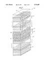
- FIG. 1is a schematic illustration of a planer, current-guided, GaAs/AlGaAs top surface emitting vertical cavity laser with a number of patterned objects on the top surface of the top mirror region in accordance with the present invention
- FIG. 2is a schematic illustration of a top portion of a VCSEL in accordance with the present invention, with a number of patterned objects disposed on a selected layer of the top mirror region;
- FIG. 3is a schematic illustration of a top portion of a VCSEL in accordance with the present invention, with a number of patterned vias disposed within a selected layer of the top mirror region;
- FIG. 4is a schematic illustration of a top portion of a VCSEL in accordance with the present invention, wherein a selected layer of the top mirror region is heavily doped, beyond the saturation limit, to provide a number of randomly distributed participates therein;
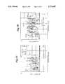
- FIG. 5A and FIG. 5Bare graphs of the optical spectrum for a VCSEL constructed in accordance with FIG. 4 at a variety of drive currents showing that even at low drive currents, a number of independent wavelengths are produced thereby;
- FIG. 6is a representation of a near field observed for a VCSEL constructed in accordance with FIG. 4, showing that the near field includes randomly distributed filament modes, each incoherent with the others;
- FIG. 7is a graph of the divergence pattern for a VCSEL constructed in accordance with FIG. 4, showing that the emission pattern is nearly symmetrical and circular, and having Full Width Half Max (FWHM) of about 24 degrees;
- FWHMFull Width Half Max
- FIG. 8is an common L-I-V graph for a VCSEL constructed in accordance with FIG. 4;
- FIG. 9is a graph of the small signal analog modulation response for a VCSEL constructed in accordance with FIG. 4, showing that even when the drive current is just above threshold, the 3 dB electrical bandwidth is greater than 3 GHz;
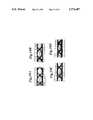
- FIGS. 10A-10Dshow a number of eye diagrams for a VCSEL constructed in accordance with FIG. 4 taken at the fiber-channel standard bit-rate of 1.062 Gbit/s as a function of bias showing a large degree of non-uniformity in the bias current can be tolerated without serious performance consequences;
- FIG. 11is a graph of the measured Bit Error Ratio (BER) vs power for a VCSEL constructed in accordance with FIG. 4, showing that even when biased up to only 1 mA below the threshold, no penalty is observed.
- BERBit Error Ratio
- FIG. 1is a schematic illustration of a planer, current-guided, GaAs/AlGaAs top surface emitting vertical cavity laser 50 with a number of patterned objects 52 disposed on the top mirror region 26.
- the n-doped substrate 14is grown by metal organic vapor phase epitaxy (MOVPE) on a 3 inch diameter n-doped GaAs substrate.
- MOVPEmetal organic vapor phase epitaxy
- the n-type mirror stack 16is preferably a 30.5 period n-doped (Te, 1 ⁇ 10 18 cm -3 , nominal) Al 0 .16 Ga 0 .84 As/AlAs bottom quarter wave stack, wherein each period contains a 200- ⁇ thick graded region.
- Spacer 18has a bottom confinement layer 20 and a top confinement layer 24, wherein each of the confinement layers is formed from Al 0 .6 Ga 0 .4 As.
- the thickness of each confinement layer 20 and 24is chosen to make the resulting spacer 18 preferably one wavelength thick.
- the active region 22is preferably a three 70- ⁇ thick GaAs quantum-well.
- the p-type mirror stack 26is preferably a 22 period p-doped (Zn, 1 ⁇ 10 18 cm -3 , nominal) Al 0 .16 Ga 0 .84 As/AlAs DBR, wherein each period contains a 200- ⁇ thick graded region. Numerous device sizes, types and arrays may be simultaneously batch-fabricated, exploiting the flexibility of this technology platform.
- the present inventioncontemplates providing a number of discrete objects 52 anywhere in the lasing cavity or in the exit aperture. That is, the discrete objects 52 may be positioned anywhere within or on the p-type mirror stack 26, the spacer 18 or the n-type mirror stack 16. In the exemplary embodiment, the discrete objects 52 may be provided on top of the p-type mirror stack 26, as shown.
- the discrete objects 52may be fabricated by using any number of materials, for example a patterned metal or dielectric material.
- a layer of metal or dielectricmay be deposited on the top surface of the p-type mirror stack 26. Using a mask, portions of the metal or dielectric layer may be selectively removed using a known etching technique to leave only the discrete objects 52. Preferably, the discrete objects 52 are randomly spaced, and are of different sizes.
- the discrete objects 52may alter the reflectance and/or resistance of the p-type mirror stack 26 at discrete locations. The altered reflectance may provide diverse-Finesse lateral subcavities in the lasing aperture. The altered resistance may provide a number of discrete locations where the injection current is increased into the active region, and thus increasing the gain at those locations. In either case, a filamented light output may be provided.
- FIG. 2is a schematic illustration of a top portion of a VCSEL 56 in accordance with the present invention.
- the illustrative embodiment shown in FIG. 2is similar to the embodiment shown in FIG. 1, except that the discrete objects 58 are disposed on a selected layer within the p-type mirror stack 26, rather than on the top layer.
- the graph shown at 60illustrates one theoretical basis for why the discrete objects may cause the VCSEL 56 to produce a filamented light output.
- the graph 60shows that the reflectance of the p-type mirror 26 may be altered at a number of discrete locations, which correspond to the discrete objects disposed within the p-type mirror stack 26.
- the discrete objects 58may produce a number of diverse-finesse lateral sub-cavities within the lasing aperture, and thus may result in a filamented light output.
- the graph shown at 62illustrates another theoretical basis for why the discrete objects 58 may cause the VCSEL 56 to produce a filamented light output.
- the graph 62shows that the injection current provided to the active region 22, by the p-type mirror 26, may be altered at a number of discrete locations. The number of discrete locations may correspond to the locations of the discrete objects 58 disposed within the p-type mirror stack 26. Because of the altered injection current, the gain of the active region 22 may also be altered at the discrete locations. These discrete gain variations are, at least in part, responsible for the filamented light output. It is recognized that the filamented output may also result from a combination of both of the above-described effects.
- FIG. 3is a schematic illustration of a top portion of a VCSEL 64 in accordance with the present invention with a number of patterned vias 66 disposed within a selected layer of the p-type mirror stack 26.
- the illustrative embodiment shown in FIG. 3is similar to the embodiment shown in FIG. 1, except that vias 66 are disposed on a selected layer within the p-type mirror stack 26.
- the graph shown at 68illustrates one theoretical basis for why the vias 66 may cause the VCSEL 64 to produce a filamented light output.
- the graph 68shows that the reflectance of the p-type mirror 26 may be altered at a number of discrete locations, which correspond to the vias 66 disposed within the p-type mirror stack 26.
- the vias 66may produce a number of diverse-finesse lateral sub-cavities within the lasing aperture, and thus may result in a filamented light output.
- the graph shown at 70illustrates another theoretical basis for why the vias 66 may cause the VCSEL 56 to produce a filamented light output.
- the graph 70shows that the injection current provided to the active region 22, by the p-type mirror 26, may be altered at a number of discrete locations. The number of discrete locations may correspond to the locations of the vias disposed within the p-type mirror stack 26. Because of the altered injection current, the gain of the active region 22 may also be altered at the discrete locations. These discrete gain alterations are, at least in part, responsible for the filamented light output. It is recognized that the filamented output may also result from a combination of both of the above-described effects.
- FIG. 4is a schematic illustration of a top portion of a VCSEL 70 in accordance with the present invention, wherein a selected layer of the top mirror region is heavily doped, beyond the saturation limit, to provide a number of randomly distributed clusters or participates 72 therein.
- a top approximately 3000 ⁇ of a selected layer within the p-type mirror stack 26is doped with Zn beyond the saturation limit (between 1 ⁇ 10 18 cm -3 and 1 ⁇ 10 19 cm -3 of Zn in AlGaAs). Because the p-type mirror stack 26 is normally a crystalline structure, doping the p-type mirror stack 26 at a concentration above the saturation limit may cause the Zn dopant atoms to be non-uniformly distributed throughout the material.
- dopant atomsmay be distributed in groups or clusters. It is these groups or clusters that are termed participates within the p-type mirror stack 26. It is believed that these participates alter the reflectance and/or resistance (and thus effective current injection) of the p-type mirror stack 26 at discrete locations, thus contributing to the filamented light output.
- the graph shown at 78illustrates one theoretical basis for why the dopants cause the VCSEL 71 to produce a filamented light output.
- the graph 78shows that the reflectance of the p-type mirror 26 may be altered at a number of discrete locations, which correspond to the participates 72 in the p-type mirror stack 26.
- the participatesmay produce a number of diverse-finesse lateral sub-cavities within the lasing aperture, and thus result in a filamented light output.
- the graph shown at 80illustrates another theoretical basis for why the dopants cause the VCSEL 71 to produce a filamented light output.
- the graph 80shows that the injection current provided to the active region 22, by the p-type mirror 26, may be altered at a number of discrete locations. The number of discrete locations may correspond to the locations of the participates 72 disposed within the p-type mirror stack 26. Because of the altered injection current, the gain of the active region 22 may also be altered at the discrete locations. These discrete gain variations are, at least in part, responsible for the filamented light output. It is recognized that the filamented output may result from a combination of both of the above-described effects. In either case, a filamented output was observed for a VCSEL constructed in accordance with FIG. 4 (see FIGS. 5A, 5B and 6 below).
- FIG. 4only shows participates in a single layer within the p-type mirror stack 26, it is contemplated that any number of layers of the p-type mirror stack 26, the n-type mirror stack 16 or the spacer 18 may be doped to provide the participates therein.
- FIG. 5A and FIG. 5Bare graphs of the optical spectrum for a VCSEL constructed in accordance with FIG. 4.
- FIG. 5Ashows the optical spectrum for a VCSEL having the top about 3000 ⁇ of the p-type mirror stack 26 heavily doped (greater than 10 18 cm -3 ) with Zn.
- the optical spectrum for a bias current of 4 mAis shown in the dark line, and the optical spectrum for a bias current of 10 mA is shown in the dashed line.
- FIG. 5Bshows the optical spectrum for a bias current of 16 mA in the dark line, and shows the optical spectrum for a bias current of 22 mA in the dashed line.
- the VCSEL of the present inventionproduces about 15 independent wavelengths.
- the VCSELproduces about 20 independent wavelengths.
- the optical spectrumis wide enough (about 5 nm) for incoherence but narrow enough not to be overly limited by fiber chromatic dispersion.
- FIG. 6is a representation of a near field observed for a VCSEL constructed in accordance with FIG. 4.
- the near fieldincludes a number of randomly distributed filament modes, each mutually incoherent with one another. Further, each filament has a slightly different modal size, and experiences a different temperature, depending on the filaments location within the lasing cavity. Thus, each filament produces a slightly different wavelength.
- FIG. 7shows the resulting divergence pattern for the near field shown in FIG. 6.
- the divergence patternis the incoherent superposition of the number of filaments (and some multi-modes), resulting in a nearly circularly symmetric emission pattern of about 24 degrees Full Width Half Maximum (FWHM). This corresponds to an average (1/e 2 ) filament diameter of approximately 1.8 microns.
- FWHMFull Width Half Maximum
- FIG. 8is a common L-I-V graph for a VCSEL constructed in accordance with FIG. 4. It has been found that threshold currents and voltages were commonly below 2 mA and 1.8V, respectively, over an 830 to 860 nm wavelength regime. The temperature performance of these VCSELs was found to be similar to more conventional VCSELs, and the threshold current typically varied by less than ⁇ 0.5 mA, at 860 nm, over a 130° C. temperature range of -10° C. to 120° C. This illustrates the robustness and practicality of the present invention.
- FIG. 9is a graph of the small signal analog modulation response for a VCSEL constructed in accordance with FIG. 4.
- the VCSELwas packaged on a microwave header including a "K" connector terminated into a 50 ⁇ Alumina line.
- a Hewlett PackardTM 8510 network analyzerwas used to make the small signal measurements together with a New FocusTM 25 GHz photo diode detector.
- FIG. 9shows that even when the drive current is just above threshold (e.g. 4 mA), the 3 dB bandwidth is greater than 3 GHz. At a typical drive current of 8 mA, the 3 dB bandwidth is about 8.3 GHz. With a 20 mA drive current, the 3 dB bandwidth is about 9.5 GHz.
- For low drive currentse.g. less than 10 mA
- multi-GHz bandwidthsare obtained. This is far greater than standard LED devices or even typical CD laser sources.
- FIG. 10shows a number of eye diagrams for a VCSEL constructed in accordance with FIG. 4 taken at the fiber-channel standard bit-rate of 1.062 Gbit/s as a function of bias.
- the VCSELwas butt-coupled through a 100 meter 62.5 ⁇ m/125 ⁇ m standard graded index multi-mode fiber.
- the filamented outputwas detected using a Hewlett PackardTM 83412B detector and displayed on a digitizing oscilloscope with a limiting bandwidth of about 1 GHz, acting as a system filter.
- FIG. 10shows a number of eye diagrams for a VCSEL constructed in accordance with FIG. 4 taken at the fiber-channel standard bit-rate of 1.062 Gbit/s as a function of bias.
- FIG. 11is a graph of the measured Bit Error Ratio (BER) vs power for a VCSEL constructed in accordance with FIG. 4.
- BERBit Error Ratio
Landscapes
- Physics & Mathematics (AREA)
- Condensed Matter Physics & Semiconductors (AREA)
- General Physics & Mathematics (AREA)
- Electromagnetism (AREA)
- Optics & Photonics (AREA)
- Semiconductor Lasers (AREA)
Abstract
Description
Claims (36)
Priority Applications (1)
| Application Number | Priority Date | Filing Date | Title |
|---|---|---|---|
| US08/734,403US5774487A (en) | 1996-10-16 | 1996-10-16 | Filamented multi-wavelength vertical-cavity surface emitting laser |
Applications Claiming Priority (1)
| Application Number | Priority Date | Filing Date | Title |
|---|---|---|---|
| US08/734,403US5774487A (en) | 1996-10-16 | 1996-10-16 | Filamented multi-wavelength vertical-cavity surface emitting laser |
Publications (1)
| Publication Number | Publication Date |
|---|---|
| US5774487Atrue US5774487A (en) | 1998-06-30 |
Family
ID=24951562
Family Applications (1)
| Application Number | Title | Priority Date | Filing Date |
|---|---|---|---|
| US08/734,403Expired - LifetimeUS5774487A (en) | 1996-10-16 | 1996-10-16 | Filamented multi-wavelength vertical-cavity surface emitting laser |
Country Status (1)
| Country | Link |
|---|---|
| US (1) | US5774487A (en) |
Cited By (54)
| Publication number | Priority date | Publication date | Assignee | Title |
|---|---|---|---|---|
| US5976903A (en)* | 1997-02-10 | 1999-11-02 | Electronics And Telecommunications Research Institute | Method for manufacturing tunable laser |
| US6064683A (en)* | 1997-12-12 | 2000-05-16 | Honeywell Inc. | Bandgap isolated light emitter |
| WO2002005038A3 (en)* | 2000-07-10 | 2002-04-25 | Corp For Laser Optics Res | Systems and methods for speckle reduction through bandwidth enhancement |
| GB2370688A (en)* | 2000-10-05 | 2002-07-03 | Agilent Technologies Inc | Vertical cavity surface emitting laser |
| US20020085610A1 (en)* | 2000-12-29 | 2002-07-04 | Morgan Robert A. | Spatially modulated reflector for an optoelectronic device |
| US20020106160A1 (en)* | 2000-12-29 | 2002-08-08 | Honeywell International Inc. | Resonant reflector for increased wavelength and polarization control |
| US6515305B2 (en) | 2000-09-18 | 2003-02-04 | Regents Of The University Of Minnesota | Vertical cavity surface emitting laser with single mode confinement |
| US6534331B2 (en) | 2001-07-24 | 2003-03-18 | Luxnet Corporation | Method for making a vertical-cavity surface emitting laser with improved current confinement |
| US6542527B1 (en) | 1998-08-27 | 2003-04-01 | Regents Of The University Of Minnesota | Vertical cavity surface emitting laser |
| US20030063629A1 (en)* | 2001-09-27 | 2003-04-03 | Davis Monica K. | Multimode fiber laser gratings |
| US20030072523A1 (en)* | 2001-10-10 | 2003-04-17 | Chih-Hsiang Lin | Optical fiber with mirror for semiconductor laser |
| US6553053B2 (en) | 2001-07-25 | 2003-04-22 | Luxnet Corporation | Vertical cavity surface emitting laser having improved light output function |
| US6606199B2 (en) | 2001-10-10 | 2003-08-12 | Honeywell International Inc. | Graded thickness optical element and method of manufacture therefor |
| US20030211642A1 (en)* | 2000-08-31 | 2003-11-13 | Honeywell International Inc. | Protective side wall passivation for VCSEL chips |
| US6680963B2 (en) | 2001-07-24 | 2004-01-20 | Lux Net Corporation | Vertical-cavity surface emitting laser utilizing a reversed biased diode for improved current confinement |
| US20040042518A1 (en)* | 2002-09-03 | 2004-03-04 | Tatum James A. | Single mode VCSEL |
| US20040066819A1 (en)* | 2000-11-28 | 2004-04-08 | Johnson Ralph H. | Versatile method and system for single mode VCSELs |
| US20040081215A1 (en)* | 2002-10-28 | 2004-04-29 | Honeywell International Inc. | Distributed bragg reflector for optoelectronic device |
| US20040101009A1 (en)* | 2002-11-21 | 2004-05-27 | Honeywell International Inc. | Long wavelength VCSEL with tunnel junction, and implant |
| US6782027B2 (en) | 2000-12-29 | 2004-08-24 | Finisar Corporation | Resonant reflector for use with optoelectronic devices |
| US20040222363A1 (en)* | 2003-05-07 | 2004-11-11 | Honeywell International Inc. | Connectorized optical component misalignment detection system |
| US20040247250A1 (en)* | 2003-06-03 | 2004-12-09 | Honeywell International Inc. | Integrated sleeve pluggable package |
| US20040264530A1 (en)* | 2003-06-27 | 2004-12-30 | Honeywell International Inc. | VCSEL having thermal management |
| US20040264536A1 (en)* | 2003-06-27 | 2004-12-30 | Honeywell International Inc. | Dielectric VCSEL gain guide |
| US20040264531A1 (en)* | 2003-06-27 | 2004-12-30 | Honeywell International Inc. | Enhanced lateral oxidation |
| US20050013336A1 (en)* | 2003-07-18 | 2005-01-20 | Eastman Kodak Company | Organic vertical cavity laser array device with varying pixel sizes |
| US20050013539A1 (en)* | 2003-07-17 | 2005-01-20 | Honeywell International Inc. | Optical coupling system |
| US20050014390A1 (en)* | 2003-07-18 | 2005-01-20 | Honeywell International Inc. | Edge bead control method and apparatus |
| US20050013553A1 (en)* | 2003-07-16 | 2005-01-20 | Honeywell International Inc. | Optical coupling system |
| US20050013542A1 (en)* | 2003-07-16 | 2005-01-20 | Honeywell International Inc. | Coupler having reduction of reflections to light source |
| US20050030992A1 (en)* | 1999-08-30 | 2005-02-10 | Thornton Robert L. | Near field optical apparatus |
| US20050031011A1 (en)* | 2000-11-28 | 2005-02-10 | Biard James R. | Electron affinity engineered VCSELs |
| US20050036533A1 (en)* | 2000-12-29 | 2005-02-17 | Honeywell To Finisar | Tunable detector |
| US20050092710A1 (en)* | 2003-10-29 | 2005-05-05 | Biard James R. | Long wavelength VCSEL device processing |
| US6961489B2 (en) | 2003-06-30 | 2005-11-01 | Finisar Corporation | High speed optical system |
| US20060043278A1 (en)* | 2004-08-30 | 2006-03-02 | Honeywell International Inc. | VCSEL pin sensor |
| US20060045162A1 (en)* | 2004-08-31 | 2006-03-02 | Finisar Corporation | Distributed bragg reflector for optoelectronic device |
| US20060056762A1 (en)* | 2003-07-02 | 2006-03-16 | Honeywell International Inc. | Lens optical coupler |
| US20060126022A1 (en)* | 2004-12-14 | 2006-06-15 | Govorkov Sergei V | Laser illuminated projection displays |
| US20060125969A1 (en)* | 2004-12-14 | 2006-06-15 | Chilla Juan L | Laser illuminated projection displays |
| US20060268954A1 (en)* | 2004-08-31 | 2006-11-30 | Johnson Ralph H | Light emitting semiconductor device having an electrical confinement barrier near the active region |
| US7149383B2 (en) | 2003-06-30 | 2006-12-12 | Finisar Corporation | Optical system with reduced back reflection |
| US20070063140A1 (en)* | 2005-09-22 | 2007-03-22 | Honeywell International Inc. | Optical particulate sensor in oil quality detection |
| US20070070302A1 (en)* | 2005-09-29 | 2007-03-29 | Govorkov Sergei V | Speckle reduction in laser illuminated projection displays having a one-dimensional spatial light modulator |
| US7298942B2 (en) | 2003-06-06 | 2007-11-20 | Finisar Corporation | Pluggable optical optic system having a lens fiber stop |
| US20080023688A1 (en)* | 2006-07-31 | 2008-01-31 | Finisar Corporation | Efficient carrier injection in a semiconductor device |
| US7433381B2 (en) | 2003-06-25 | 2008-10-07 | Finisar Corporation | InP based long wavelength VCSEL |
| US7466404B1 (en)* | 2005-06-03 | 2008-12-16 | Sun Microsystems, Inc. | Technique for diagnosing and screening optical interconnect light sources |
| US20090109658A1 (en)* | 2007-10-26 | 2009-04-30 | Corporation For Laser Optics Research | Laser illuminated backlight for flat panel displays |
| US20090302336A1 (en)* | 2008-06-06 | 2009-12-10 | Hong Kong Applied Science And Technology Research Institute | Semiconductor wafers and semiconductor devices and methods of making semiconductor wafers and devices |
| US20100182536A1 (en)* | 2009-01-16 | 2010-07-22 | Corporation For Laser Optics Research | Laser illuminated backlight for liquid crystal displays |
| US20100200880A1 (en)* | 2008-06-06 | 2010-08-12 | Hong Kong Applied Science And Technology Research Institute Co. Ltd. | Semiconductor wafers and semiconductor devices and methods of making semiconductor wafers and devices |
| US8031752B1 (en) | 2007-04-16 | 2011-10-04 | Finisar Corporation | VCSEL optimized for high speed data |
| US20120188354A1 (en)* | 2011-01-24 | 2012-07-26 | Elizabeth Alice Munro | System and method for optical imaging with vertical cavity surface emitting lasers |
Citations (35)
| Publication number | Priority date | Publication date | Assignee | Title |
|---|---|---|---|---|
| US4317085A (en)* | 1979-09-12 | 1982-02-23 | Xerox Corporation | Channeled mesa laser |
| US4660207A (en)* | 1984-11-21 | 1987-04-21 | Northern Telecom Limited | Surface-emitting light emitting device |
| US4784722A (en)* | 1985-01-22 | 1988-11-15 | Massachusetts Institute Of Technology | Method forming surface emitting diode laser |
| US4885592A (en)* | 1987-12-28 | 1989-12-05 | Kofol J Stephen | Electronically steerable antenna |
| US4901327A (en)* | 1988-10-24 | 1990-02-13 | General Dynamics Corporation, Electronics Division | Transverse injection surface emitting laser |
| US4943970A (en)* | 1988-10-24 | 1990-07-24 | General Dynamics Corporation, Electronics Division | Surface emitting laser |
| US4956844A (en)* | 1989-03-17 | 1990-09-11 | Massachusetts Institute Of Technology | Two-dimensional surface-emitting laser array |
| US5031187A (en)* | 1990-02-14 | 1991-07-09 | Bell Communications Research, Inc. | Planar array of vertical-cavity, surface-emitting lasers |
| US5052016A (en)* | 1990-05-18 | 1991-09-24 | University Of New Mexico | Resonant-periodic-gain distributed-feedback surface-emitting semiconductor laser |
| US5056098A (en)* | 1990-07-05 | 1991-10-08 | At&T Bell Laboratories | Vertical cavity laser with mirror having controllable reflectivity |
| US5062115A (en)* | 1990-12-28 | 1991-10-29 | Xerox Corporation | High density, independently addressable, surface emitting semiconductor laser/light emitting diode arrays |
| US5068869A (en)* | 1987-06-19 | 1991-11-26 | Lockheed Missiles & Space Company, Inc. | Surface-emitting laser diode |
| US5115442A (en)* | 1990-04-13 | 1992-05-19 | At&T Bell Laboratories | Top-emitting surface emitting laser structures |
| US5140605A (en)* | 1991-06-27 | 1992-08-18 | Xerox Corporation | Thermally stabilized diode laser structure |
| US5158908A (en)* | 1990-08-31 | 1992-10-27 | At&T Bell Laboratories | Distributed bragg reflectors and devices incorporating same |
| US5216263A (en)* | 1990-11-29 | 1993-06-01 | Xerox Corporation | High density, independently addressable, surface emitting semiconductor laser-light emitting diode arrays |
| US5237581A (en)* | 1990-11-14 | 1993-08-17 | Nec Corporation | Semiconductor multilayer reflector and light emitting device with the same |
| US5245622A (en)* | 1992-05-07 | 1993-09-14 | Bandgap Technology Corporation | Vertical-cavity surface-emitting lasers with intra-cavity structures |
| US5258990A (en)* | 1991-11-07 | 1993-11-02 | The United States Of America As Represented By The Secretary Of The United States Department Of Energy | Visible light surface emitting semiconductor laser |
| US5293392A (en)* | 1992-07-31 | 1994-03-08 | Motorola, Inc. | Top emitting VCSEL with etch stop layer |
| US5325386A (en)* | 1992-04-21 | 1994-06-28 | Bandgap Technology Corporation | Vertical-cavity surface emitting laser assay display system |
| US5331654A (en)* | 1993-03-05 | 1994-07-19 | Photonics Research Incorporated | Polarized surface-emitting laser |
| US5349599A (en)* | 1990-03-29 | 1994-09-20 | Larkins Eric C | Bistable optical laser based on a heterostructure PNPN thyristor |
| US5351256A (en)* | 1993-04-28 | 1994-09-27 | The United States Of America As Represented By The United States Department Of Energy | Electrically injected visible vertical cavity surface emitting laser diodes |
| US5359447A (en)* | 1993-06-25 | 1994-10-25 | Hewlett-Packard Company | Optical communication with vertical-cavity surface-emitting laser operating in multiple transverse modes |
| US5363397A (en)* | 1992-10-29 | 1994-11-08 | Internatioal Business Machines Corporation | Integrated short cavity laser with bragg mirrors |
| US5373520A (en)* | 1992-08-12 | 1994-12-13 | Fujitsu Limited | Surface emitting laser and method of manufacturing the same |
| US5404373A (en)* | 1991-11-08 | 1995-04-04 | University Of New Mexico | Electro-optical device |
| US5416044A (en)* | 1993-03-12 | 1995-05-16 | Matsushita Electric Industrial Co., Ltd. | Method for producing a surface-emitting laser |
| US5428634A (en)* | 1992-11-05 | 1995-06-27 | The United States Of America As Represented By The United States Department Of Energy | Visible light emitting vertical cavity surface emitting lasers |
| US5446754A (en)* | 1993-11-05 | 1995-08-29 | Photonics Research Incorporated | Phased array semiconductor laser |
| US5513202A (en)* | 1994-02-25 | 1996-04-30 | Matsushita Electric Industrial Co., Ltd. | Vertical-cavity surface-emitting semiconductor laser |
| US5530715A (en)* | 1994-11-29 | 1996-06-25 | Motorola, Inc. | Vertical cavity surface emitting laser having continuous grading |
| US5657157A (en)* | 1995-06-23 | 1997-08-12 | Sdl, Inc. | Semiconductor optical amplifying media with reduced self-focusing |
| US5659568A (en)* | 1995-05-23 | 1997-08-19 | Hewlett-Packard Company | Low noise surface emitting laser for multimode optical link applications |
- 1996
- 1996-10-16USUS08/734,403patent/US5774487A/ennot_activeExpired - Lifetime
Patent Citations (37)
| Publication number | Priority date | Publication date | Assignee | Title |
|---|---|---|---|---|
| US4317085A (en)* | 1979-09-12 | 1982-02-23 | Xerox Corporation | Channeled mesa laser |
| US4660207A (en)* | 1984-11-21 | 1987-04-21 | Northern Telecom Limited | Surface-emitting light emitting device |
| US4784722A (en)* | 1985-01-22 | 1988-11-15 | Massachusetts Institute Of Technology | Method forming surface emitting diode laser |
| US5068869A (en)* | 1987-06-19 | 1991-11-26 | Lockheed Missiles & Space Company, Inc. | Surface-emitting laser diode |
| US4885592A (en)* | 1987-12-28 | 1989-12-05 | Kofol J Stephen | Electronically steerable antenna |
| US4901327A (en)* | 1988-10-24 | 1990-02-13 | General Dynamics Corporation, Electronics Division | Transverse injection surface emitting laser |
| US4943970A (en)* | 1988-10-24 | 1990-07-24 | General Dynamics Corporation, Electronics Division | Surface emitting laser |
| US4956844A (en)* | 1989-03-17 | 1990-09-11 | Massachusetts Institute Of Technology | Two-dimensional surface-emitting laser array |
| US5031187A (en)* | 1990-02-14 | 1991-07-09 | Bell Communications Research, Inc. | Planar array of vertical-cavity, surface-emitting lasers |
| US5349599A (en)* | 1990-03-29 | 1994-09-20 | Larkins Eric C | Bistable optical laser based on a heterostructure PNPN thyristor |
| US5115442A (en)* | 1990-04-13 | 1992-05-19 | At&T Bell Laboratories | Top-emitting surface emitting laser structures |
| US5052016A (en)* | 1990-05-18 | 1991-09-24 | University Of New Mexico | Resonant-periodic-gain distributed-feedback surface-emitting semiconductor laser |
| US5056098A (en)* | 1990-07-05 | 1991-10-08 | At&T Bell Laboratories | Vertical cavity laser with mirror having controllable reflectivity |
| US5158908A (en)* | 1990-08-31 | 1992-10-27 | At&T Bell Laboratories | Distributed bragg reflectors and devices incorporating same |
| US5237581A (en)* | 1990-11-14 | 1993-08-17 | Nec Corporation | Semiconductor multilayer reflector and light emitting device with the same |
| US5216263A (en)* | 1990-11-29 | 1993-06-01 | Xerox Corporation | High density, independently addressable, surface emitting semiconductor laser-light emitting diode arrays |
| US5317170A (en)* | 1990-11-29 | 1994-05-31 | Xerox Corporation | High density, independently addressable, surface emitting semiconductor laser/light emitting diode arrays without a substrate |
| US5062115A (en)* | 1990-12-28 | 1991-10-29 | Xerox Corporation | High density, independently addressable, surface emitting semiconductor laser/light emitting diode arrays |
| US5337074A (en)* | 1990-12-28 | 1994-08-09 | Xerox Corporation | Opto-electronic line printer having a high density, independently addressable, surface emitting semiconductor laser/light emitting diode array |
| US5140605A (en)* | 1991-06-27 | 1992-08-18 | Xerox Corporation | Thermally stabilized diode laser structure |
| US5258990A (en)* | 1991-11-07 | 1993-11-02 | The United States Of America As Represented By The Secretary Of The United States Department Of Energy | Visible light surface emitting semiconductor laser |
| US5404373A (en)* | 1991-11-08 | 1995-04-04 | University Of New Mexico | Electro-optical device |
| US5325386A (en)* | 1992-04-21 | 1994-06-28 | Bandgap Technology Corporation | Vertical-cavity surface emitting laser assay display system |
| US5245622A (en)* | 1992-05-07 | 1993-09-14 | Bandgap Technology Corporation | Vertical-cavity surface-emitting lasers with intra-cavity structures |
| US5293392A (en)* | 1992-07-31 | 1994-03-08 | Motorola, Inc. | Top emitting VCSEL with etch stop layer |
| US5373520A (en)* | 1992-08-12 | 1994-12-13 | Fujitsu Limited | Surface emitting laser and method of manufacturing the same |
| US5363397A (en)* | 1992-10-29 | 1994-11-08 | Internatioal Business Machines Corporation | Integrated short cavity laser with bragg mirrors |
| US5428634A (en)* | 1992-11-05 | 1995-06-27 | The United States Of America As Represented By The United States Department Of Energy | Visible light emitting vertical cavity surface emitting lasers |
| US5331654A (en)* | 1993-03-05 | 1994-07-19 | Photonics Research Incorporated | Polarized surface-emitting laser |
| US5416044A (en)* | 1993-03-12 | 1995-05-16 | Matsushita Electric Industrial Co., Ltd. | Method for producing a surface-emitting laser |
| US5351256A (en)* | 1993-04-28 | 1994-09-27 | The United States Of America As Represented By The United States Department Of Energy | Electrically injected visible vertical cavity surface emitting laser diodes |
| US5359447A (en)* | 1993-06-25 | 1994-10-25 | Hewlett-Packard Company | Optical communication with vertical-cavity surface-emitting laser operating in multiple transverse modes |
| US5446754A (en)* | 1993-11-05 | 1995-08-29 | Photonics Research Incorporated | Phased array semiconductor laser |
| US5513202A (en)* | 1994-02-25 | 1996-04-30 | Matsushita Electric Industrial Co., Ltd. | Vertical-cavity surface-emitting semiconductor laser |
| US5530715A (en)* | 1994-11-29 | 1996-06-25 | Motorola, Inc. | Vertical cavity surface emitting laser having continuous grading |
| US5659568A (en)* | 1995-05-23 | 1997-08-19 | Hewlett-Packard Company | Low noise surface emitting laser for multimode optical link applications |
| US5657157A (en)* | 1995-06-23 | 1997-08-12 | Sdl, Inc. | Semiconductor optical amplifying media with reduced self-focusing |
Non-Patent Citations (44)
| Title |
|---|
| Banwell et al., "VCSE Laser Transmitters for Parallel Data Links", IEEE Jornal of Quantum Electronics, vol. 29, No. 2, Feb. 1993, pp. 635-644. |
| Banwell et al., VCSE Laser Transmitters for Parallel Data Links , IEEE Jornal of Quantum Electronics , vol. 29, No. 2, Feb. 1993, pp. 635 644.* |
| Catchmark et al., "High Temperature CW Operation of Vertical Cavity Top Surface-Emitting Lasers", CLEO 1993. (no month available) p. 138. |
| Catchmark et al., High Temperature CW Operation of Vertical Cavity Top Surface Emitting Lasers , CLEO 1993. (no month available) p. 138.* |
| Chemla et al., "Nonlinear Optical Properties of Semiconductor Quantum Wells", Optical Nonlinearities and Instabilities in Semiconductors, Academic Press, Inc., Copyright 1988, pp. 83-120. |
| Chemla et al., Nonlinear Optical Properties of Semiconductor Quantum Wells , Optical Nonlinearities and Instabilities in Semiconductors , Academic Press, Inc., Copyright 1988, pp. 83 120.* |
| Choa et al., "High-Speed Modulation of Vertical-Cavity Surface-Emitting Lasers", IEEE Photonics Technology Letters, vol. 3, No. 8, Aug. 1991, pp. 697-699. |
| Choa et al., High Speed Modulation of Vertical Cavity Surface Emitting Lasers , IEEE Photonics Technology Letters , vol. 3, No. 8, Aug. 1991, pp. 697 699.* |
| Jewell et al., "Surface-Emitting Microlasers for Photonic Switching and Interchip Connections", Optical Engineering, vol. 29, No. 3, Mar. 1990, pp. 210-214. |
| Jewell et al., Surface Emitting Microlasers for Photonic Switching and Interchip Connections , Optical Engineering , vol. 29, No. 3, Mar. 1990, pp. 210 214.* |
| Jiang et al., "High-Frequency Polarization Self-Modulation in Vertical-Cavity Surface-Emitting Lasers", Appl. Phys. Letters, vol. 63, No. 26, Dec. 27, 1993, pp. 2545-2547. |
| Jiang et al., High Frequency Polarization Self Modulation in Vertical Cavity Surface Emitting Lasers , Appl. Phys. Letters , vol. 63, No. 26, Dec. 27, 1993, pp. 2545 2547.* |
| Lee et al., "Top-Surface-Emitting GaAs Four-Quantum-Well Lasers Emitting at 0-85 μm", Electronic Letters, vol. 26, No. 11, May 24, 1990, pp. 710-711. |
| Lee et al., Top Surface Emitting GaAs Four Quantum Well Lasers Emitting at 0 85 m , Electronic Letters , vol. 26, No. 11, May 24, 1990, pp. 710 711.* |
| Lehman et al., "High-Frequency Modulation Characteristics of Hybrid Dielectric/AlGaAs Mirror Singlemode VCSELs", Electronic Letters, vol. 31, No. 15, Jul. 20, 1995, pp. 1251-1252. |
| Lehman et al., High Frequency Modulation Characteristics of Hybrid Dielectric/AlGaAs Mirror Singlemode VCSELs , Electronic Letters , vol. 31, No. 15, Jul. 20, 1995, pp. 1251 1252.* |
| Miller et al., "Optical Bistability Due to Increasing Absorption", Optics Letters, vol. 9, No. 5, May 1984, pp. 162-164. |
| Miller et al., Optical Bistability Due to Increasing Absorption , Optics Letters , vol. 9, No. 5, May 1984, pp. 162 164.* |
| Morgan et al., "200° C., 96-nm Wavelength Range, Continuous-Wave Lasing from Unbonded GaAs MOVPE-Grown Vertical Cavity Surface-Emitting Lasers", IEEE Photonics Technology Letters, vol. 7, No. 5, May 1995, pp. 441-443. |
| Morgan et al., "High-Power Coherently Coupled 8×8 Vertical Cavity Surface Emitting Laser Array", Appl. Phys. Lett., vol. 61, No. 10, Sep. 7, 1992, pp. 1160-1162. |
| Morgan et al., "Hybrid Dielectric/AlGaAs Mirror Spatially Filtered Vertical Cavity Top-Surface Emitting Laser", Appl. Phys. Lett., vol. 66, No. 10, Mar. 6, 1995, pp. 1157-1159. |
| Morgan et al., "Novel Hybrid-DBR Single-Mode Controlled GaAs Top-Emitting VCSEL with Record Low Voltage" no date available. |
| Morgan et al., "Progress and Properties of High-Power Coherent Vertical Cavity Surface Emitting Laser Arrays", SPIE, vol. 1850, pp. 100-108. Jan., 1993. |
| Morgan et al., "Progress in Planarized Vertical Cavity Surface Emitting Laser Devices and Arrays", SPIE, vol. 1562, pp. 149-159. Jul., 1991. |
| Morgan et al., "Spatial-Filtered Vertical-Cavity Top Surface-Emitting Lasers", CLEO, 1993. (no month available) pp. 138-139. |
| Morgan et al., "Submilliamp, Low-Resistance, Continuous-Wave, Single-Mode GaAs Planar Vertical-Cavity Surface Emitting Lasers", Honeywell Technology Center, Jun. 6, 1995. |
| Morgan et al., "Transverse Mode Control of Vertical-Cavity Top-Surface-Emitting Lasers", IEEE Photonics Technology Letters, vol. 4, No. 4, Apr. 1993, pp. 374-377. |
| Morgan et al., "Vertical-Cavity Surface-Emitting Laser Arrays", SPIE, vol. 2398, pp. 65-93. Feb., 1995. |
| Morgan et al., 200 C., 96 nm Wavelength Range, Continuous Wave Lasing from Unbonded GaAs MOVPE Grown Vertical Cavity Surface Emitting Lasers , IEEE Photonics Technology Letters , vol. 7, No. 5, May 1995, pp. 441 443.* |
| Morgan et al., High Power Coherently Coupled 8 8 Vertical Cavity Surface Emitting Laser Array , Appl. Phys. Lett. , vol. 61, No. 10, Sep. 7, 1992, pp. 1160 1162.* |
| Morgan et al., Hybrid Dielectric/AlGaAs Mirror Spatially Filtered Vertical Cavity Top Surface Emitting Laser , Appl. Phys. Lett. , vol. 66, No. 10, Mar. 6, 1995, pp. 1157 1159.* |
| Morgan et al., Novel Hybrid DBR Single Mode Controlled GaAs Top Emitting VCSEL with Record Low Voltage no date available.* |
| Morgan et al., Progress and Properties of High Power Coherent Vertical Cavity Surface Emitting Laser Arrays , SPIE , vol. 1850, pp. 100 108. Jan., 1993.* |
| Morgan et al., Progress in Planarized Vertical Cavity Surface Emitting Laser Devices and Arrays , SPIE , vol. 1562, pp. 149 159. Jul., 1991.* |
| Morgan et al., Spatial Filtered Vertical Cavity Top Surface Emitting Lasers , CLEO, 1993. (no month available) pp. 138 139.* |
| Morgan et al., Submilliamp, Low Resistance, Continuous Wave, Single Mode GaAs Planar Vertical Cavity Surface Emitting Lasers , Honeywell Technology Center, Jun. 6, 1995.* |
| Morgan et al., Transverse Mode Control of Vertical Cavity Top Surface Emitting Lasers , IEEE Photonics Technology Letters , vol. 4, No. 4, Apr. 1993, pp. 374 377.* |
| Morgan et al., Vertical Cavity Surface Emitting Laser Arrays , SPIE , vol. 2398, pp. 65 93. Feb., 1995.* |
| Morgan, "High-Performance, Producible Vertical Cavity Lasers for Optical Interconnects", High Speed Electronics and Systems, vol. 5, No. 4, Dec. 1994, pp. 65-95. |
| Morgan, "Vertical Cavity Surface Emitting Lasers: The Next Generation", SPIE, vol. 1992, pp. 64-89. Jul. 1993. |
| Morgan, High Performance, Producible Vertical Cavity Lasers for Optical Interconnects , High Speed Electronics and Systems , vol. 5, No. 4, Dec. 1994, pp. 65 95.* |
| Morgan, Vertical Cavity Surface Emitting Lasers: The Next Generation , SPIE , vol. 1992, pp. 64 89. Jul. 1993.* |
| Nugent et al., "Self-Pulsations in Vertical-Cavity Surface-Emitting Lasers", Electronic Letters, vol. 31, No. 1, Jan. 5, 1995, pp. 43-44. |
| Nugent et al., Self Pulsations in Vertical Cavity Surface Emitting Lasers , Electronic Letters , vol. 31, No. 1, Jan. 5, 1995, pp. 43 44.* |
Cited By (106)
| Publication number | Priority date | Publication date | Assignee | Title |
|---|---|---|---|---|
| US5976903A (en)* | 1997-02-10 | 1999-11-02 | Electronics And Telecommunications Research Institute | Method for manufacturing tunable laser |
| US6064683A (en)* | 1997-12-12 | 2000-05-16 | Honeywell Inc. | Bandgap isolated light emitter |
| US6542527B1 (en) | 1998-08-27 | 2003-04-01 | Regents Of The University Of Minnesota | Vertical cavity surface emitting laser |
| US20050030992A1 (en)* | 1999-08-30 | 2005-02-10 | Thornton Robert L. | Near field optical apparatus |
| US7483465B2 (en)* | 1999-08-30 | 2009-01-27 | Research Investment Network, Inc. | Near field optical apparatus |
| US6975294B2 (en) | 2000-07-10 | 2005-12-13 | Corporation For Laser Optics Research | Systems and methods for speckle reduction through bandwidth enhancement |
| WO2002005038A3 (en)* | 2000-07-10 | 2002-04-25 | Corp For Laser Optics Res | Systems and methods for speckle reduction through bandwidth enhancement |
| US20020196414A1 (en)* | 2000-07-10 | 2002-12-26 | Manni Jeffrey Glenn | Systems and methods for speckle reduction through bandwidth enhancement |
| US20030211642A1 (en)* | 2000-08-31 | 2003-11-13 | Honeywell International Inc. | Protective side wall passivation for VCSEL chips |
| US6924161B2 (en) | 2000-08-31 | 2005-08-02 | Finisar Corporation | Protective side wall passivation for VCSEL chips |
| US6674777B1 (en) | 2000-08-31 | 2004-01-06 | Honeywell International Inc. | Protective side wall passivation for VCSEL chips |
| US6515305B2 (en) | 2000-09-18 | 2003-02-04 | Regents Of The University Of Minnesota | Vertical cavity surface emitting laser with single mode confinement |
| GB2370688A (en)* | 2000-10-05 | 2002-07-03 | Agilent Technologies Inc | Vertical cavity surface emitting laser |
| US7092425B1 (en)* | 2000-10-05 | 2006-08-15 | Avago Technologies General Ip (Singapore) Ptd. Ltd. | VCSEL device with improved modal properties |
| US20040213311A1 (en)* | 2000-11-28 | 2004-10-28 | Johnson Ralph H | Single mode vertical cavity surface emitting laser |
| US7221691B2 (en) | 2000-11-28 | 2007-05-22 | Finisar Corporation | Versatile method and system for single mode VCSELs |
| US7065124B2 (en) | 2000-11-28 | 2006-06-20 | Finlsar Corporation | Electron affinity engineered VCSELs |
| US6905900B1 (en) | 2000-11-28 | 2005-06-14 | Finisar Corporation | Versatile method and system for single mode VCSELs |
| US7308011B2 (en) | 2000-11-28 | 2007-12-11 | Finisar Corporation | Versatile method and system for single mode VCSELs |
| US20040066819A1 (en)* | 2000-11-28 | 2004-04-08 | Johnson Ralph H. | Versatile method and system for single mode VCSELs |
| US20040066820A1 (en)* | 2000-11-28 | 2004-04-08 | Johnson Ralph H. | Versatile method and system for single mode VCSELs |
| US20050031011A1 (en)* | 2000-11-28 | 2005-02-10 | Biard James R. | Electron affinity engineered VCSELs |
| US7288421B2 (en) | 2000-12-29 | 2007-10-30 | Finisar Corporation | Method for forming an optoelectronic device having an isolation layer |
| US20050036533A1 (en)* | 2000-12-29 | 2005-02-17 | Honeywell To Finisar | Tunable detector |
| US6782027B2 (en) | 2000-12-29 | 2004-08-24 | Finisar Corporation | Resonant reflector for use with optoelectronic devices |
| US20040188695A1 (en)* | 2000-12-29 | 2004-09-30 | Morgan Robert A. | Laser with resonant reflector |
| US20040191941A1 (en)* | 2000-12-29 | 2004-09-30 | Morgan Robert A. | Method for producing laser with resonant reflector |
| US8599897B2 (en) | 2000-12-29 | 2013-12-03 | Finisar Corporation | Tunable detector |
| US6727520B2 (en) | 2000-12-29 | 2004-04-27 | Honeywell International Inc. | Spatially modulated reflector for an optoelectronic device |
| US20020106160A1 (en)* | 2000-12-29 | 2002-08-08 | Honeywell International Inc. | Resonant reflector for increased wavelength and polarization control |
| US20020085610A1 (en)* | 2000-12-29 | 2002-07-04 | Morgan Robert A. | Spatially modulated reflector for an optoelectronic device |
| US6836501B2 (en) | 2000-12-29 | 2004-12-28 | Finisar Corporation | Resonant reflector for increased wavelength and polarization control |
| US7266135B2 (en) | 2000-12-29 | 2007-09-04 | Finisar Corporation | Method for producing laser with resonant reflector |
| US7760786B2 (en) | 2000-12-29 | 2010-07-20 | Finisar Corporation | Laser with resonant reflector |
| US6680963B2 (en) | 2001-07-24 | 2004-01-20 | Lux Net Corporation | Vertical-cavity surface emitting laser utilizing a reversed biased diode for improved current confinement |
| US6534331B2 (en) | 2001-07-24 | 2003-03-18 | Luxnet Corporation | Method for making a vertical-cavity surface emitting laser with improved current confinement |
| US6553053B2 (en) | 2001-07-25 | 2003-04-22 | Luxnet Corporation | Vertical cavity surface emitting laser having improved light output function |
| US20030063629A1 (en)* | 2001-09-27 | 2003-04-03 | Davis Monica K. | Multimode fiber laser gratings |
| US6669367B2 (en)* | 2001-10-10 | 2003-12-30 | Applied Optoelectronics, Inc. | Optical fiber with mirror for semiconductor laser |
| US20030072523A1 (en)* | 2001-10-10 | 2003-04-17 | Chih-Hsiang Lin | Optical fiber with mirror for semiconductor laser |
| US6606199B2 (en) | 2001-10-10 | 2003-08-12 | Honeywell International Inc. | Graded thickness optical element and method of manufacture therefor |
| US6965626B2 (en) | 2002-09-03 | 2005-11-15 | Finisar Corporation | Single mode VCSEL |
| US20040042518A1 (en)* | 2002-09-03 | 2004-03-04 | Tatum James A. | Single mode VCSEL |
| US6990135B2 (en) | 2002-10-28 | 2006-01-24 | Finisar Corporation | Distributed bragg reflector for optoelectronic device |
| US20040081215A1 (en)* | 2002-10-28 | 2004-04-29 | Honeywell International Inc. | Distributed bragg reflector for optoelectronic device |
| US20050190812A1 (en)* | 2002-10-28 | 2005-09-01 | Johnson Ralph H. | Distributed bragg reflector for optoelectronic device |
| US7251264B2 (en) | 2002-10-28 | 2007-07-31 | Finisar Corporation | Distributed bragg reflector for optoelectronic device |
| US6813293B2 (en) | 2002-11-21 | 2004-11-02 | Finisar Corporation | Long wavelength VCSEL with tunnel junction, and implant |
| US20040101009A1 (en)* | 2002-11-21 | 2004-05-27 | Honeywell International Inc. | Long wavelength VCSEL with tunnel junction, and implant |
| US20040222363A1 (en)* | 2003-05-07 | 2004-11-11 | Honeywell International Inc. | Connectorized optical component misalignment detection system |
| US20040247250A1 (en)* | 2003-06-03 | 2004-12-09 | Honeywell International Inc. | Integrated sleeve pluggable package |
| US7298942B2 (en) | 2003-06-06 | 2007-11-20 | Finisar Corporation | Pluggable optical optic system having a lens fiber stop |
| US7433381B2 (en) | 2003-06-25 | 2008-10-07 | Finisar Corporation | InP based long wavelength VCSEL |
| US7277461B2 (en)* | 2003-06-27 | 2007-10-02 | Finisar Corporation | Dielectric VCSEL gain guide |
| US20040264530A1 (en)* | 2003-06-27 | 2004-12-30 | Honeywell International Inc. | VCSEL having thermal management |
| US7054345B2 (en)* | 2003-06-27 | 2006-05-30 | Finisar Corporation | Enhanced lateral oxidation |
| US20040264536A1 (en)* | 2003-06-27 | 2004-12-30 | Honeywell International Inc. | Dielectric VCSEL gain guide |
| US7075962B2 (en) | 2003-06-27 | 2006-07-11 | Finisar Corporation | VCSEL having thermal management |
| US20040264531A1 (en)* | 2003-06-27 | 2004-12-30 | Honeywell International Inc. | Enhanced lateral oxidation |
| US6961489B2 (en) | 2003-06-30 | 2005-11-01 | Finisar Corporation | High speed optical system |
| US7139454B2 (en) | 2003-06-30 | 2006-11-21 | Finisar Corporation | Methods for signal transmission in optical fiber |
| US7149383B2 (en) | 2003-06-30 | 2006-12-12 | Finisar Corporation | Optical system with reduced back reflection |
| US20060056762A1 (en)* | 2003-07-02 | 2006-03-16 | Honeywell International Inc. | Lens optical coupler |
| US20050013553A1 (en)* | 2003-07-16 | 2005-01-20 | Honeywell International Inc. | Optical coupling system |
| US20050013542A1 (en)* | 2003-07-16 | 2005-01-20 | Honeywell International Inc. | Coupler having reduction of reflections to light source |
| US7210857B2 (en) | 2003-07-16 | 2007-05-01 | Finisar Corporation | Optical coupling system |
| US20050013539A1 (en)* | 2003-07-17 | 2005-01-20 | Honeywell International Inc. | Optical coupling system |
| US20050013336A1 (en)* | 2003-07-18 | 2005-01-20 | Eastman Kodak Company | Organic vertical cavity laser array device with varying pixel sizes |
| US20050014390A1 (en)* | 2003-07-18 | 2005-01-20 | Honeywell International Inc. | Edge bead control method and apparatus |
| US6928095B2 (en) | 2003-07-18 | 2005-08-09 | Eastman Kodak Company | Organic vertical cavity laser array device with varying pixel sizes |
| US6887801B2 (en) | 2003-07-18 | 2005-05-03 | Finisar Corporation | Edge bead control method and apparatus |
| US20050092710A1 (en)* | 2003-10-29 | 2005-05-05 | Biard James R. | Long wavelength VCSEL device processing |
| US7031363B2 (en) | 2003-10-29 | 2006-04-18 | Finisar Corporation | Long wavelength VCSEL device processing |
| US20060043278A1 (en)* | 2004-08-30 | 2006-03-02 | Honeywell International Inc. | VCSEL pin sensor |
| US7920612B2 (en) | 2004-08-31 | 2011-04-05 | Finisar Corporation | Light emitting semiconductor device having an electrical confinement barrier near the active region |
| US20060268954A1 (en)* | 2004-08-31 | 2006-11-30 | Johnson Ralph H | Light emitting semiconductor device having an electrical confinement barrier near the active region |
| US7596165B2 (en) | 2004-08-31 | 2009-09-29 | Finisar Corporation | Distributed Bragg Reflector for optoelectronic device |
| US20060045162A1 (en)* | 2004-08-31 | 2006-03-02 | Finisar Corporation | Distributed bragg reflector for optoelectronic device |
| US20060126022A1 (en)* | 2004-12-14 | 2006-06-15 | Govorkov Sergei V | Laser illuminated projection displays |
| US7633562B2 (en) | 2004-12-14 | 2009-12-15 | Coherent, Inc. | Laser illuminated projection displays |
| US20080143888A1 (en)* | 2004-12-14 | 2008-06-19 | Chilla Juan L | Laser illuminated projection displays |
| US7355657B2 (en) | 2004-12-14 | 2008-04-08 | Coherent, Inc. | Laser illuminated projection displays |
| US7244028B2 (en) | 2004-12-14 | 2007-07-17 | Coherent, Inc. | Laser illuminated projection displays |
| US20060125969A1 (en)* | 2004-12-14 | 2006-06-15 | Chilla Juan L | Laser illuminated projection displays |
| US7466404B1 (en)* | 2005-06-03 | 2008-12-16 | Sun Microsystems, Inc. | Technique for diagnosing and screening optical interconnect light sources |
| US7321117B2 (en) | 2005-09-22 | 2008-01-22 | Honeywell International Inc. | Optical particulate sensor in oil quality detection |
| US20070063140A1 (en)* | 2005-09-22 | 2007-03-22 | Honeywell International Inc. | Optical particulate sensor in oil quality detection |
| US7413311B2 (en) | 2005-09-29 | 2008-08-19 | Coherent, Inc. | Speckle reduction in laser illuminated projection displays having a one-dimensional spatial light modulator |
| US20070070302A1 (en)* | 2005-09-29 | 2007-03-29 | Govorkov Sergei V | Speckle reduction in laser illuminated projection displays having a one-dimensional spatial light modulator |
| US20080023688A1 (en)* | 2006-07-31 | 2008-01-31 | Finisar Corporation | Efficient carrier injection in a semiconductor device |
| US7829912B2 (en) | 2006-07-31 | 2010-11-09 | Finisar Corporation | Efficient carrier injection in a semiconductor device |
| US8031752B1 (en) | 2007-04-16 | 2011-10-04 | Finisar Corporation | VCSEL optimized for high speed data |
| US8152351B2 (en) | 2007-10-26 | 2012-04-10 | Corporation For Laser Optics Research | Laser illuminated backlight for flat panel displays |
| USRE44949E1 (en)* | 2007-10-26 | 2014-06-17 | Corporation For Laser Optics Research | Laser illuminated backlight for flat panel displays |
| US20110075067A1 (en)* | 2007-10-26 | 2011-03-31 | Corporation For Laser Optics Research | Laser illuminated backlight for flat panel displays |
| US7866869B2 (en) | 2007-10-26 | 2011-01-11 | Corporation For Laser Optics Research | Laser illuminated backlight for flat panel displays |
| USRE47887E1 (en) | 2007-10-26 | 2020-03-03 | Dolby Laboratories Licensing Corporation | Laser illuminated backlight for flat panel displays |
| USRE46664E1 (en) | 2007-10-26 | 2018-01-09 | Dolby Laboratories Licensing Corporation | Laser illuminated backlight for flat panel displays |
| US20090109658A1 (en)* | 2007-10-26 | 2009-04-30 | Corporation For Laser Optics Research | Laser illuminated backlight for flat panel displays |
| US20100200880A1 (en)* | 2008-06-06 | 2010-08-12 | Hong Kong Applied Science And Technology Research Institute Co. Ltd. | Semiconductor wafers and semiconductor devices and methods of making semiconductor wafers and devices |
| US20090302336A1 (en)* | 2008-06-06 | 2009-12-10 | Hong Kong Applied Science And Technology Research Institute | Semiconductor wafers and semiconductor devices and methods of making semiconductor wafers and devices |
| US8395168B2 (en)* | 2008-06-06 | 2013-03-12 | Hong Kong Applied Science And Technology Research Institute Co. Ltd. | Semiconductor wafers and semiconductor devices with polishing stops and method of making the same |
| US20100182536A1 (en)* | 2009-01-16 | 2010-07-22 | Corporation For Laser Optics Research | Laser illuminated backlight for liquid crystal displays |
| US8334946B2 (en) | 2009-01-16 | 2012-12-18 | Corporation For Laser Optics Research | Laser illuminated backlight for liquid crystal displays |
| US9253419B2 (en)* | 2011-01-24 | 2016-02-02 | The Governing Council Of The University Of Toronto | System and method for optical imaging with vertical cavity surface emitting lasers |
| US20120188354A1 (en)* | 2011-01-24 | 2012-07-26 | Elizabeth Alice Munro | System and method for optical imaging with vertical cavity surface emitting lasers |
Similar Documents
| Publication | Publication Date | Title |
|---|---|---|
| US5774487A (en) | Filamented multi-wavelength vertical-cavity surface emitting laser | |
| CA2622301C (en) | Optical phase conjugation laser diode | |
| Chang-Hasnain et al. | Multiple wavelength tunable surface-emitting laser arrays | |
| US7020172B2 (en) | Long wavelength vertical cavity surface emitting laser | |
| US5903590A (en) | Vertical-cavity surface-emitting laser device | |
| US6760357B1 (en) | Vertical cavity apparatus with tunnel junction | |
| US5978401A (en) | Monolithic vertical cavity surface emitting laser and resonant cavity photodetector transceiver | |
| US6535541B1 (en) | Vertical cavity apparatus with tunnel junction | |
| US7288421B2 (en) | Method for forming an optoelectronic device having an isolation layer | |
| US6487230B1 (en) | Vertical cavity apparatus with tunnel junction | |
| US6493373B1 (en) | Vertical cavity apparatus with tunnel junction | |
| US20050053112A1 (en) | Surface emitting dfb laser structures for broadband communication systems and array of same | |
| EP1025625B1 (en) | Filamented multi-wavelength vertical-cavity surface emitting laser and fabrication method | |
| US6487231B1 (en) | Vertical cavity apparatus with tunnel junction | |
| JP2002299742A (en) | Vertical cavity surface emitting laser, method of manufacturing the same, and communication system | |
| US6687280B1 (en) | Vertical-cavity surface-emitting laser device | |
| US6882673B1 (en) | Mirror structure for reducing the effect of feedback on a VCSEL | |
| US6490311B1 (en) | Vertical cavity apparatus with tunnel junction | |
| US20020126720A1 (en) | Device structure and method for fabricating semiconductor lasers | |
| US7095771B2 (en) | Implant damaged oxide insulating region in vertical cavity surface emitting laser | |
| Lei et al. | InGaAs‐GaAs quantum well vertical‐cavity surface‐emitting laser using molecular beam epitaxial regrowth | |
| JP2002217488A (en) | Surface emitting laser element, surface emitting laser system, wavelength adjusting method, surface emitting laser array, optical interconnection system, and local area network system | |
| Yang et al. | Monolithic oxide-confined multiple-wavelength vertical-cavity surface-emitting laser arrays with a 57-nm wavelength grading range using an oxidized upper Bragg mirror | |
| Nishiyama et al. | Long-wavelength VCSELs on InP grown by MOCVD | |
| Kaneko | VCSEL: Vertical Cavity Surface-Emitting Laser |
Legal Events
| Date | Code | Title | Description |
|---|---|---|---|
| AS | Assignment | Owner name:HONEYWELL, INC., MINNESOTA Free format text:ASSIGNMENT OF ASSIGNORS INTEREST;ASSIGNOR:MORGAN, ROBERT A.;REEL/FRAME:008277/0517 Effective date:19961015 | |
| STCF | Information on status: patent grant | Free format text:PATENTED CASE | |
| FEPP | Fee payment procedure | Free format text:PAYOR NUMBER ASSIGNED (ORIGINAL EVENT CODE: ASPN); ENTITY STATUS OF PATENT OWNER: LARGE ENTITY | |
| FPAY | Fee payment | Year of fee payment:4 | |
| AS | Assignment | Owner name:FINISAR CORPORATION, CALIFORNIA Free format text:ASSIGNMENT OF ASSIGNORS INTEREST;ASSIGNOR:HONEYWELL INTERNATIONAL, INC.;REEL/FRAME:014468/0371 Effective date:20040301 Owner name:FINISAR CORPORATION, CALIFORNIA Free format text:ASSIGNMENT OF ASSIGNORS INTEREST;ASSIGNOR:HONEYWELL INTERNATIONAL, INC.;REEL/FRAME:014468/0407 Effective date:20040301 Owner name:FINISAR CORPORATION, CALIFORNIA Free format text:ASSIGNMENT OF ASSIGNORS INTEREST;ASSIGNOR:HONEYWELL INTERNATIONAL, INC.;REEL/FRAME:014484/0171 Effective date:20040301 | |
| AS | Assignment | Owner name:FINISAR CORPORATION, CALIFORNIA Free format text:ASSIGNMENT OF ASSIGNORS INTEREST;ASSIGNOR:HONEYWELL INTERNATIONAL, INC.;REEL/FRAME:014499/0365 Effective date:20040301 | |
| FPAY | Fee payment | Year of fee payment:8 | |
| FPAY | Fee payment | Year of fee payment:12 | |
| AS | Assignment | Owner name:II-VI DELAWARE, INC., DELAWARE Free format text:ASSIGNMENT OF ASSIGNORS INTEREST;ASSIGNOR:FINISAR CORPORATION;REEL/FRAME:052286/0001 Effective date:20190924 |