US5774273A - Variable-geometry liquid-filled lens apparatus and method for controlling the energy distribution of a light beam - Google Patents
Variable-geometry liquid-filled lens apparatus and method for controlling the energy distribution of a light beamDownload PDFInfo
- Publication number
- US5774273A US5774273AUS08/702,785US70278596AUS5774273AUS 5774273 AUS5774273 AUS 5774273AUS 70278596 AUS70278596 AUS 70278596AUS 5774273 AUS5774273 AUS 5774273A
- Authority
- US
- United States
- Prior art keywords
- optically transparent
- microcells
- liquid
- membrane
- region
- Prior art date
- Legal status (The legal status is an assumption and is not a legal conclusion. Google has not performed a legal analysis and makes no representation as to the accuracy of the status listed.)
- Expired - Lifetime
Links
- 239000007788liquidSubstances0.000titleclaimsabstractdescription121
- 238000000034methodMethods0.000titleclaimsdescription12
- 239000012528membraneSubstances0.000claimsabstractdescription64
- 230000003287optical effectEffects0.000claimsabstractdescription26
- 239000012530fluidSubstances0.000claimsdescription30
- 238000004891communicationMethods0.000claimsdescription12
- 238000006073displacement reactionMethods0.000claimsdescription5
- 239000007787solidSubstances0.000claimsdescription4
- 239000011521glassSubstances0.000abstractdescription14
- 230000000694effectsEffects0.000abstractdescription13
- 239000012780transparent materialSubstances0.000abstract2
- 210000004027cellAnatomy0.000description68
- 230000008901benefitEffects0.000description8
- 230000009471actionEffects0.000description5
- 230000007246mechanismEffects0.000description5
- 238000010586diagramMethods0.000description4
- 239000000463materialSubstances0.000description4
- 239000000203mixtureSubstances0.000description4
- 230000002093peripheral effectEffects0.000description4
- 210000002421cell wallAnatomy0.000description3
- 230000033001locomotionEffects0.000description3
- 238000007493shaping processMethods0.000description3
- 230000003068static effectEffects0.000description3
- 208000002740Muscle RigidityDiseases0.000description2
- 239000003570airSubstances0.000description2
- 238000003491arrayMethods0.000description2
- 239000004568cementSubstances0.000description2
- 230000014509gene expressionEffects0.000description2
- 238000005286illuminationMethods0.000description2
- 231100000252nontoxicToxicity0.000description2
- 230000003000nontoxic effectEffects0.000description2
- 229920002379silicone rubberPolymers0.000description2
- 239000004945silicone rubberSubstances0.000description2
- 239000000853adhesiveSubstances0.000description1
- 230000001070adhesive effectEffects0.000description1
- XAGFODPZIPBFFR-UHFFFAOYSA-NaluminiumChemical compound[Al]XAGFODPZIPBFFR-UHFFFAOYSA-N0.000description1
- 229910052782aluminiumInorganic materials0.000description1
- 239000012080ambient airSubstances0.000description1
- 230000015572biosynthetic processEffects0.000description1
- 210000000170cell membraneAnatomy0.000description1
- 230000001413cellular effectEffects0.000description1
- 230000008859changeEffects0.000description1
- 238000010276constructionMethods0.000description1
- 230000003247decreasing effectEffects0.000description1
- 230000009977dual effectEffects0.000description1
- 239000000945fillerSubstances0.000description1
- 230000008014freezingEffects0.000description1
- 238000007710freezingMethods0.000description1
- 238000009499grossingMethods0.000description1
- 230000010354integrationEffects0.000description1
- 239000002991molded plasticSubstances0.000description1
- 230000007935neutral effectEffects0.000description1
- 239000003921oilSubstances0.000description1
- 239000004033plasticSubstances0.000description1
- 229920001296polysiloxanePolymers0.000description1
- 230000008569processEffects0.000description1
- 230000004044responseEffects0.000description1
- 229920002545silicone oilPolymers0.000description1
- 239000013585weight reducing agentSubstances0.000description1
Images


Classifications
- F—MECHANICAL ENGINEERING; LIGHTING; HEATING; WEAPONS; BLASTING
- F21—LIGHTING
- F21V—FUNCTIONAL FEATURES OR DETAILS OF LIGHTING DEVICES OR SYSTEMS THEREOF; STRUCTURAL COMBINATIONS OF LIGHTING DEVICES WITH OTHER ARTICLES, NOT OTHERWISE PROVIDED FOR
- F21V17/00—Fastening of component parts of lighting devices, e.g. shades, globes, refractors, reflectors, filters, screens, grids or protective cages
- F21V17/02—Fastening of component parts of lighting devices, e.g. shades, globes, refractors, reflectors, filters, screens, grids or protective cages with provision for adjustment
- F—MECHANICAL ENGINEERING; LIGHTING; HEATING; WEAPONS; BLASTING
- F21—LIGHTING
- F21V—FUNCTIONAL FEATURES OR DETAILS OF LIGHTING DEVICES OR SYSTEMS THEREOF; STRUCTURAL COMBINATIONS OF LIGHTING DEVICES WITH OTHER ARTICLES, NOT OTHERWISE PROVIDED FOR
- F21V5/00—Refractors for light sources
- F21V5/04—Refractors for light sources of lens shape
- G—PHYSICS
- G02—OPTICS
- G02B—OPTICAL ELEMENTS, SYSTEMS OR APPARATUS
- G02B3/00—Simple or compound lenses
- G02B3/12—Fluid-filled or evacuated lenses
- G02B3/14—Fluid-filled or evacuated lenses of variable focal length
- F—MECHANICAL ENGINEERING; LIGHTING; HEATING; WEAPONS; BLASTING
- F21—LIGHTING
- F21W—INDEXING SCHEME ASSOCIATED WITH SUBCLASSES F21K, F21L, F21S and F21V, RELATING TO USES OR APPLICATIONS OF LIGHTING DEVICES OR SYSTEMS
- F21W2131/00—Use or application of lighting devices or systems not provided for in codes F21W2102/00-F21W2121/00
- F21W2131/40—Lighting for industrial, commercial, recreational or military use
- F21W2131/406—Lighting for industrial, commercial, recreational or military use for theatres, stages or film studios
- F—MECHANICAL ENGINEERING; LIGHTING; HEATING; WEAPONS; BLASTING
- F21—LIGHTING
- F21Y—INDEXING SCHEME ASSOCIATED WITH SUBCLASSES F21K, F21L, F21S and F21V, RELATING TO THE FORM OR THE KIND OF THE LIGHT SOURCES OR OF THE COLOUR OF THE LIGHT EMITTED
- F21Y2115/00—Light-generating elements of semiconductor light sources
- F21Y2115/10—Light-emitting diodes [LED]
Definitions
- the present inventionrelates to lighting instruments, and especially devices for controlling light beam divergence or convergence of wash luminaires used in theatrical and architectural illumination.
- Automated luminairesalso include within their housings motorized mechanisms for varying the many parameters.
- a motorized yoke assemblymay be used for adjusting the pan and tilt of the lamp housing; motorized mechanisms may be used for moving color filters for adjusting the color of the light beam; and lenses and other beam shaping devices coupled to motorized mechanisms may be used for adjusting the size and shape of the light beam.
- Control electronics responsive to control signal inputsmay also be included within the lamp housing and/or the motorized yoke assembly.
- Bornhorst U.S. Pat. No. 4,392,187describes a system which has been found to work well in actual practice. In all modern theatrical luminaires, and especially with respect to automated luminaires with pan and tilt heads, a consistent design goal has been to decrease luminaire size, weight and operating noise while increasing the number of functions which can be performed and the range of variability of the function.
- a wash luminairecan produce such an effect using a light source and a spherical reflector which are moveable with respect to a lens.
- the divergence angle of the light beamvaries depending upon the position of the source and reflector with respect to the lens.
- the Cadenza PCmanufactured by Rank Strand of the United Kingdom and the 2KW Fresnel manufactured by Mole-Richardson of California and others, use the same optical system to control the divergence angle of the light beam projected by the luminaire.
- the systemconsists of a positive, or convex, front lens illuminated by a lamp and retroreflector combination.
- the retroreflectorserves to collect and redirect energy that is radiated backwards from the lamp and return it forward to the filament area thereby increasing the apparent brightness of the source.
- the lamp and reflector combinationare moveable along the optical axis of the lens.
- the Cadenza luminaireuses a normal plano-convex lens, while the 2KW Fresnel luminaire uses a common molded glass Fresnel form of the plano-convex lens.
- U.S. Pat. No. 4,602,321Another common system for controlling the divergence angle of a light beam is disclosed in U.S. Pat. No. 4,602,321; and uses a lamp which is moveable with respect to a parabolic reflector. When the lamp is placed at the focus of the reflector, a relatively columnar light beam emerges and projects a small spot of light. As the lamp is moved rearwardly along the optical axis of the reflector and away from the focus of the reflector, the beam diverges from columnar to form a larger spot of light.
- This systemrequires an adjustable carriage for the lamp socket, and frequently requires provisions for minor (manual) adjustments along two additional axes orthogonal to the optical axis, so as to maintain proper alignment of the lamp on the optical axis, in addition to (motorized) adjustment along the optical axis for controlling beam divergence.
- a convection-cooled automated luminaire described in U.S. Pat. No. 5,367,444utilizes a 1000 watt incandescent lamp and an eight-inch, cold-mirror reflector coupled to a cast aluminum heat sink to project a light beam through four banks of pivoting light filters radially arranged about the optical axis of the luminaire. Three banks of filters are used to control the color of the beam, and the fourth bank of filters is used to control beam divergence.
- the lampis dimmed electronically by a separate power supply.
- An eight-inch diameter glass lenscovers the exit aperture.
- An assortment of different front lensesis available, the choice of which affects the amount and type of beam divergence which can be controlled.
- the fourth filter bankis converted to a dimmer, substituting opaque filter panels in place of textured glass panels, since an arc lamp cannot be electronically dimmed from full to zero without extinguishing the arc. This leaves an unfulfilled requirement for an apparatus to control beam divergence that fits in space available in the existing luminaire housing.
- a further object of the inventionis to provide a new and improved apparatus and method for controlling the divergence or convergence of a light beam, including an automated liquid cell lens which projects a homogenous light beam.
- a still further object of the inventionis to provide a new and improved apparatus and method for controlling the divergence or convergence of a light beam, including an automated liquid cell lens which is useful in a stage lighting or architectural environment such that an operator can continuously adjust the coverage provided by the lighting instrument over a large range.
- a systemwhich includes an automated liquid cell lens for controlling the divergence or convergence of a beam of light emanating from a luminaire.
- the systemcomprises three elements:
- a liquid cellconsisting of a rigid structure supporting flexible and transparent walls.
- the cellis filled with an optically clear fluid, such as silicone oil, that resists freezing and biological growth, and is also non-toxic and non-flammable.
- an optically clear fluidsuch as silicone oil
- the flexible wallsmust be tight enough to remain flat and parallel under the static weight of the internal fluid. The walls must also deform when a pressure differential exists between the fluid pressure and the static air pressure.
- a hydraulic cylinderserves as a fluid reservoir and pressure source, and is connected to the liquid cell by a tube.
- a linear actuatoris capable of moving the hydraulic cylinder piston in discrete steps to meter an exact amount of fluid to or from the cell with each step.
- the rigid structurecomprises an array of microcells providing fluid communication paths between and among the various microcells, each microcell supporting at least one flexible wall which operates as a variable-geometry lenslet.
- the individual microcellscan be any convenient shape, but the geometry of each microcell affects the shape of the lenslet formed by the corresponding flexible wall thereby affecting the light distribution pattern of the whole array.
- the flexible wallsmay be of a constant thickness across each microcell, but the thickness of each flexible wall can be varied across each microcell to further affect the light distribution pattern of the whole array.
- FIG. 1is a block diagram of an optical system in accordance with the present invention wherein a liquid cell lens is in an optically powerless state;
- FIG. 2is a block diagram of an optical system in accordance with the present invention wherein a liquid cell lens has negative power and is diverging light;
- FIG. 3is a block diagram of an optical system in accordance with the present invention wherein a liquid cell lens has positive power and is converging light;
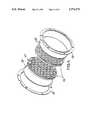
- FIG. 4is a perspective view of a preferred embodiment of the liquid cell lens in accordance with the present invention wherein hexagonal microcells are arrayed in a honeycomb formation;
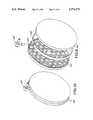
- FIG. 5is a perspective view of a liquid cell lens in accordance with the present invention wherein hexagonal microcells are arrayed in a two-piece structure supporting separate flexible membranes;
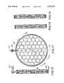
- FIG. 6is a plan view of the liquid cell lens structure shown in FIG. 5;
- FIG. 7is a cross sectional view taken along lines A--A of the liquid cell lens structure shown in FIG. 6;
- FIG. 8is a cross-sectional view taken along lines B--B of the liquid cell lens structure shown in FIG. 6;
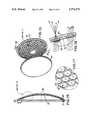
- FIG. 9is a perspective view of a liquid cell lens in accordance with the present invention wherein hexagonal microcells are arrayed in a two-piece structure with integral flexible membranes as features of molded, hermaphroditic halves;
- FIG. 10is a perspective view of an assembled liquid cell lens structure shown in FIG. 9;
- FIG. 11is a plan view of the liquid cell lens structure shown in FIG. 10;
- FIG. 12is a cross-sectional view taken along lines A--A of the liquid cell lens structure shown in FIG. 11;
- FIG. 13is a cross-sectional view taken along lines B--B of the liquid cell lens structure shown in FIG. 11;
- FIG. 14is across-sectional view taken along lines C--C of the liquid cell lens structure shown in FIG. 11;
- FIG. 15is a perspective view of the most preferred embodiment of the invention, a one-piece array of microcells with an integral flexible membrane mounted to a front glass;
- FIG. 16a cross-sectional view of the assembled one-piece array of microcells mounted to a front glass which is shown in FIG. 15;
- FIG. 17is a perspective detail view of the microcell array shown in FIG. 15;
- FIG. 18is a sectional detail view of the assembled one-piece array of microcells shown in FIG. 16;
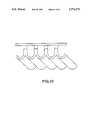
- FIG. 19is a plan view of a multi-cellular array according to a further aspect of the invention, showing plural regions of the cellular array and separate actuators for each region;
- FIG. 20is a sectional view of microcells, in a powerless state, of a region shown in FIG. 19;
- FIG. 21is a sectional view of microcells, in a positive power state, of a region shown in FIG. 19;
- FIG. 22is a perspective view of the microcells shown in FIG. 21 in a positive power state
- FIG. 23is a sectional view of microcells, in a powerless state, according to another aspect of the invention.
- FIG. 24is a sectional view of microcells, in a wedge state, according to another aspect of the invention.
- FIG. 1shows a block diagram of a lighting instrument incorporating an apparatus that includes a liquid cell lens in accordance with the present invention.
- Light source 10, reflector 12 and liquid cell lens 14are shown encased within luminaire housing 16.
- a typical wash luminaire reflector 12may be parabolic in shape.
- light source 10 and reflector 12cooperate to produce a directed beam of light.
- Liquid cell lens 14may be located at any convenient distance from the reflector within the luminaire housing.
- a simple liquid cell lenshas a rigid outer periphery 18, supporting two parallel, spaced membranes 20A and 20B essentially orthogonal to the beam axis.
- rigid outer periphery member 18is annular in shape.
- Liquid cell membranes 20A and 20Bmust be deformable in response to pressure changes within the lens. They must also be optically transparent.
- the size of the liquid cell lensshould be commensurate in scope so as to encompass the diameter of the beam.
- the thickness of the liquid cellshould be such that when the desired concave curvature of the opposing membranes 20A and 20B is attained, they do not touch.
- Liquid cell lens 14is connected in fluid communication via one or more ports 24 to interconnect piping 26 and optical liquid variable volume reservoir 28. Together, these elements form a closed system. Interconnect piping 26 and reservoir 28 may be conveniently located within or outside the luminaire housing 16, and located away from heat sources.
- the optically clear liquid 30should be of a composition that will not freeze at normally encountered temperatures, will not support biological growth and is non-toxic and non-flammable.
- a silicone fluidis preferred but some organic oils may also be acceptable.
- the composition of an acceptable optically clear liquidwill depend upon the other components of the liquid cell system.
- displacement pump 32is provided in communication with reservoir 28.
- This pumpmust be of a type capable of pressurizing the fluid contained in the reservoir and lens system.
- FIG. 1shows the pump assembly as a linear actuator 34 coupled to a hydraulic piston 36, and reservoir/hydraulic cylinder 28.
- Other types of displacement pumpscould be chosen by one of skill in the art.
- the pump assembly, in FIG. 1 comprised of hydraulic cylinder 28, hydraulic piston 36 and linear actuator 34,may be located within or outside the luminaire housing 16 as convenient provided the reservoir may be sufficiently pressurized and depressurized to deform the flexible walls of the liquid cell lens 14.
- FIG. 1shows the lighting instrument in a neutral state in which the liquid cell lens has no significant effect on the light beam since its transparent membranes 20A and 20B are essentially parallel to one another and orthogonal to the beam. In this condition, the lens has no effect on the beam of light.
- Operation of the pump 32 to withdraw optically clear liquid 30 from the liquid cell lens 14results in coordinated concave deformation (or bowing) of the opposing transparent flexible membranes 20A and 20B by the ambient air pressure to form a bi-concave lens of varying negative power depending upon how much optical liquid is removed from the liquid cell lens.
- the effect of this operationis shown in FIG. 2, wherein the liquid cell lens serves to diverge the light beam and enlarge the area covered by the beam.
- One of skill in the artwill be able to operate a liquid cell lens of the type disclosed to produce a wide continuum of differing beam divergence angles.
- Shaping the opposing flexible transparent membranes 20A and 20B into increasingly concave surfaces to achieve a wider beam divergencerequires transporting substantial amounts of optically clear fluid from the liquid cell to the reservoir. For example, in an annular cell approximately eight inches in diameter, approximately 8.5 cubic inches of liquid would need to be withdrawn in order to convert the liquid cell lens from a dual parallel surface purely zero power to a biconcave negative-power optical element having a radius of approximately twelve inches.
- FIG. 2the increased fluid 30 in the reservoir 28 is depicted, as is the lateral movement of the hydraulic piston 36 through the driving actuator 34.
- the actuator 34is depicted as under direct control of a system controller 40. It will be appreciated that a linear actuator such as that made by Haydon Switch Inc. is especially suited to the present invention because of size, force generated and cost.
- FIG. 3depicts the opposite condition, in which optically clear fluid 30 has been pumped by the lateral movement of the hydraulic piston 36 from reservoir 28 to the liquid cell lens 14.
- the opposing deformable transparent membranes 20A and 20Bbulge or bow outward forming a bi-convex lens as shown in FIG. 3.
- the liquid cellacts as a positive-power optical element converging the light beam, which is concentrated to a smaller area thereby increasing its intensity.
- the ability to reduce beam coverageis proportional to the curvature of the liquid cell's transparent membranes 20A and 20B.
- a wash light of the type disclosedis very useful in lighting a stage because an operator is able to continuously adjust the coverage provided by a general purpose washlight over a wide range of areas.
- a preferred liquid cell lensincludes an array of microcells supporting opposing selectively deformable transparent membranes 20A and 20B (not shown). These microcells 48 are formed from any convenient shape and pattern of microcell walls 50 and the two opposing transparent membranes 20A and 20B. Although any number and shape of microcells may be selected for a given application, the specific cell geometry having a particular effect upon the shape of a light beam, a hexagonal honeycomb as shown in FIG. 4 is found to provide an acceptable mix of strength, weight, and cell coverage. Microcell walls should be more inflexible than the deformable transparent membranes 20A and 20B but need not be as rigid as the rigid outer periphery member 18. Microcell walls should also be as transparent as possible thereby avoiding light blockage. A particularly preferred material for the microcell walls as shown in FIG. 4 is plastic.
- Channels in the microcell wallsallow for flow of optically clear liquid between the microcells thereby equalizing pressure.
- channels 52provide for the flow of optically clear liquid between the microcells and ultimately in and out of the liquid cell lens array through port(s) 24 (not shown in FIG. 4). Acceptable variations of channels 52 which permit the flow of liquid between the microcells would be immediately apparent to one of skill in the art.
- the inventionalso contemplates another embodiment of the liquid cell lens in which an array of microcells is formed by two pieces, each piece including half of the rigid cell supporting membranes.
- molded hexagonal honeycomb pieces 56form the structural walls of the microcell array.
- a flexible film membrane 58is glued to each honeycomb structure 56.
- Elbow fitting 60is captured between the two honeycomb structural pieces.
- the whole microcell array lensis held together by lens clamps 54 secured with suitable fasteners (not shown).
- Structural pieces 56are rigid, transparent molded plastic.
- the flexible film 58may be a transparent silicone rubber.
- the elbow fitting 60connects the piping 26 to the liquid cell lens for transportation of the optically clear liquid 30 to the lens.
- FIG. 6shows a plan view of the liquid cell lens structure of FIG. 5 with sections A--A and B--B.
- FIG. 7is a cross-sectional view taken along lines A--A of the structure shown in FIG. 6 and
- FIG. 8is a cross-sectional view taken along lines B--B of the structure shown in FIG. 6.
- channels 52form liquid passages between and among the microcells of molded hexagonal honeycomb 56.
- FIG. 9shows an alternate embodiment of a two-piece microcell array in which each molded piece 64 includes the rigid structural walls of the microcell array with an integral membrane forming the flexible walls.
- the structural wallsare molded to be thicker than the flexible walls, to provide rigidity for the structural walls.
- Peripheral channels 65 formed in each piece 64accept annular structural member 62 when the microcell array lens is assembled, thereby associating the elbow fitting 60 in combination with the microcell structural pieces 64.
- Annular structural member 62provides peripheral rigidity in addition to locating the elbow fitting.
- FIG. 10illustrates the assembled embodiment of FIG. 9.
- FIG. 11shows a plan view of the liquid cell lens structure of FIG. 9 with sections A--A, B--B and C--C.
- FIG. 12is a cross-sectional view taken along lines A--A of the structure shown in FIG. 9.
- FIG. 13is a crosssectional view taken along lines B--B of the structure shown in FIG. 9.
- FIG. 14is a cross-sectional view taken along lines C--C of the structure shown in FIG. 9.
- channels 52form liquid passages between and among the microcells of the liquid cell lens structure of FIG. 9.
- the liquid cell lens assemblyconsists of two parts: a flexible membrane 70 with features molded into one surface that form a hexagonal support structure 72 for refracting lenslets 74 (see FIG. 17); and a mounting surface 80 made of glass or other clear, rigid material. Membrane 70 and mounting surface 80 are bonded together forming a sealed assembly that can be filled with a liquid and pressurized through inlet hole 76.
- FIG. 16is a cross-sectional view taken along lines A--A of the structure shown in FIG. 15.
- the membrane 70 shown in FIG. 16is formed into a generally convex shape that conforms to the concave inner surface of the preferred glass mounting surface 80.
- the outer periphery of the membrane 71has sufficient thickness to support the diaphragm during the mounting process.
- membrane support posts 73extend from the support structure between the lenslets 74. The posts make contact with the inner surface of the glass mounting surface 80 when the flexible membrane 70 and the mounting surface 80 are mated together.
- the lens assemblyis adhesively bonded with an optically clear cement that has an index of refraction closely matching the lens membrane material and the liquid filler.
- the adhesiveis spread over the concave surface of the mounting surface 80 and around the edge of the glass.
- a complete sealis formed between the edge 71 of flexible membrane 70 and a periphery of the mounting surface 80 except for the area of the inlet hole.
- the membrane support posts 73are bonded to the inner surface of the glass.
- FIG. 18shows how the fluid pressure distends the cell surfaces 78 and forms a near spherical lenslet with optical power to diverge the light beam passing through the lens.
- the curved glass mount 80also serves to further diverge the light beam since the lenslets are spherically arrayed over a small solid angle centered on the optical axis 90 (shown in FIG. 16) of the light beam. If the lenslets are not distended by fluid pressure, the spherical shape of the mount has little effect on the light beam.
- each microcellis a small concave or convex element of the same optical power of the larger single cell yet having the displacement of a smaller volume of optical liquid.
- Another advantageis that a larger number of microcells provides even greater integration or smoothing of the light across the beam. There is, however, a practical limit. As the number of cells increases, there is an increase in undeformed area where cell walls support the membrane.
- An array of hexagonal microcellsyields an array of near spherical lenslets as the flexible wall of each microcell distends into a dome of near spherical profile under pressure.
- An array of rectangular microcellssuch as shown in FIG. 19, yields an array of cylindrical lenslets that refract light symmetrically to either side of its long axis if the flexible membrane covering the microcells has a constant thickness across each cell.
- a complex liquid cell lens apparatus 100has a single flexible membrane mounted to a glass plate, similar to that shown in FIG. 15, except that the flexible membrane is formed having plural, separately controllable regions 101 through 105.
- a central region 105has a hexagonal array of spherical microcells (hexagonal microcells might also be used) which form spherical lenslets when distended under positive pressure.
- Peripheral regions 101 through 104have arrays of rectangular microcells which form cylindrical lenslets, as shown in FIG. 22, when distended under pressure.
- the microcells of each regioninclude channels interconnecting the various microcells in manner described hereinbefore, to allow for liquid flow between and among the microcells of each region, but the various regions are isolated from each other to prevent liquid flow between regions. Any number, pattern or shape of different regions, including the specific geometry of the individual microcells contained in a region, may be selected for a given application.
- Region 101includes a liquid inlet port 121 to which is connected a pipe 106 for carrying optically clear liquid between the liquid cell lens and reservoir/hydraulic cylinder 107.
- the clear liquidflows into and/or out of port 121 to control the action of the microcells and lenslets of region 101.
- Actuator 108is coupled to cylinder 107 to effect liquid flow as described hereinbefore.
- region 102includes inlet port 122 to which is connected pipe 109 communicating clear liquid from cylinder 110 coupled to actuator 111.
- Region 103includes inlet port 123 to which is connected pipe 115 communicating clear liquid from cylinder 116 coupled to actuator 117.
- Region 104includes inlet port 124 to which is connected pipe 118 communicating clear liquid from cylinder 119 coupled to actuator 120. Regions 101 through 104 are separately controllable.
- Central region 105includes a liquid communication channel 126 which terminates in port 125.
- Channel 126conducts liquid from port 125 to the microcell array of region 105, and the channel lies between and is separate from the microcell arrays of regions 102 and 103.
- Pipe 112is connected to port 125 and communicates clear liquid from cylinder 113 coupled to actuator 114.
- the microcells of region 105are controllable separately from any of the regions 101 through 104.
- a liquid cell lens 100controls beam divergence of a central portion of a light beam by the action of microcell array region 105, and controls beam divergence of peripheral portions of the light beam by the action of microcell array regions 101 through 104.
- Region 105imparts a conical beam divergence pattern when pressurized, owing to the spherical lenslets formed by the microcells thereof.
- Regions 101 and 103impart beam divergence patterns along one axis (vertically, for example) orthogonal to a beam axis such as axis 90 as shown in FIG. 16, while regions 102 and 104 impart beam divergence patterns along another axis (horizontally, for example) orthogonal to the beam axis.
- Region 105can then be used to spread the light from the central portion of the beam while leaving the periphery of the beam unchanged.
- Regions 101 and 103can be used to increase beam divergence vertically while regions 102 and 104 can be used to increase beam divergence horizontally.
- Regions 101 and 103can be operated from a single hydraulic cylinder and actuator while regions 102 and 104 can also be operated from a single hydraulic cylinder and actuator in a system of reduced complexity.
- the system as shown in FIG. 19provides for independent divergence control of central, top, bottom, left, and right portions of a light beam projected therethrough for more precise beam shaping.
- FIGS. 20 and 21illustrate the action of the flexible diaphragm at rest (FIG. 20) and distended under pressure (FIG. 21). At rest, the light rays passing through the various microcells are undisturbed by the flat surface of the various microcells. When the surfaces of the microcells are distended under pressure, the light rays converge at a point in front of the distended surfaces and diverge thereafter to form a divergent light beam. This is similar to the action of the microcell array shown in FIGS. 15 through 18, except that the lenslets formed by the distended surfaces of the rectangular microcells of regions 101 through 104 of FIG. 19 are cylindrical lenses as shown in FIG. 22.
- a variable-thickness membrane covering the same rectangular cellforms a wedge-shaped lens that throws light to one side, as shown in FIG. 24.
- a variety of lenslet shapescan be made to yield a variety of beam divergence patterns.
- Many desired light patternscan be created with lenses incorporating these techniques. In operation, the effect of such a lens is to go from no effect on the beam while at rest to custom-designed distribution pattern of variable extent.
- microcell wallscomposed of silicone rubber have an index of refraction of approximately 1.43 while an optically clear liquid such as Dow Corning FS-1265 has an index of refraction of approximately 1.38. The cell walls disappear when the index of refraction of the clear liquid perfectly matches the index of refraction of the microcell walls.
- One of skill in the artwill be able to adjust the composition of the optically clear liquid, the size and shape of the microcells, the material of the microcell walls and the flow rates of the closed liquid system in order to maximize the desired divergence or convergence effects on the luminaire light beam.
- the disclosed liquid cell lenswould be very useful in a stage lighting environment where an operator could continuously adjust the coverage provided by a general purpose washlight.
- the devicelends itself well to automation where a local processor could change the lens power by operating the linear actuator as needed to respond to the operator's commands.
- the disclosed embodimentsprovide a highly variable, high temperature, easily controllable apparatus for controlling beam divergence which is also adapted for use in modern automated luminaires because of its relatively low weight, small size and low cost.
- a lighting apparatussuch as an architectural luminaire, intended to compliment a building or other display, can be constructed using the foregoing techniques.
- a lighting apparatussuch as an architectural luminaire, intended to compliment a building or other display, can be constructed using the foregoing techniques.
Landscapes
- Engineering & Computer Science (AREA)
- General Engineering & Computer Science (AREA)
- Physics & Mathematics (AREA)
- General Physics & Mathematics (AREA)
- Optics & Photonics (AREA)
- Mechanical Light Control Or Optical Switches (AREA)
Abstract
Description
Claims (37)
Priority Applications (3)
| Application Number | Priority Date | Filing Date | Title |
|---|---|---|---|
| US08/702,785US5774273A (en) | 1996-08-23 | 1996-08-23 | Variable-geometry liquid-filled lens apparatus and method for controlling the energy distribution of a light beam |
| PCT/US1997/015718WO1999013372A1 (en) | 1996-08-23 | 1997-09-08 | Variable-geometry liquid-filled lens apparatus and method for controlling the energy distribution of a light beam |
| TW086113688ATW364045B (en) | 1996-08-23 | 1997-09-20 | Variable-geometry liquid-filled lens apparatus and method for controlling the energy distribution of a light beam |
Applications Claiming Priority (2)
| Application Number | Priority Date | Filing Date | Title |
|---|---|---|---|
| US08/702,785US5774273A (en) | 1996-08-23 | 1996-08-23 | Variable-geometry liquid-filled lens apparatus and method for controlling the energy distribution of a light beam |
| PCT/US1997/015718WO1999013372A1 (en) | 1996-08-23 | 1997-09-08 | Variable-geometry liquid-filled lens apparatus and method for controlling the energy distribution of a light beam |
Publications (1)
| Publication Number | Publication Date |
|---|---|
| US5774273Atrue US5774273A (en) | 1998-06-30 |
Family
ID=26792747
Family Applications (1)
| Application Number | Title | Priority Date | Filing Date |
|---|---|---|---|
| US08/702,785Expired - LifetimeUS5774273A (en) | 1996-08-23 | 1996-08-23 | Variable-geometry liquid-filled lens apparatus and method for controlling the energy distribution of a light beam |
Country Status (2)
| Country | Link |
|---|---|
| US (1) | US5774273A (en) |
| WO (1) | WO1999013372A1 (en) |
Cited By (111)
| Publication number | Priority date | Publication date | Assignee | Title |
|---|---|---|---|---|
| WO1999041624A1 (en)* | 1998-02-17 | 1999-08-19 | Bonds Haakan | A device comprising an optical body |
| US6230453B1 (en) | 1998-12-01 | 2001-05-15 | Ray M. Alden | Variable view window |
| WO2001059360A1 (en)* | 2000-02-10 | 2001-08-16 | INSTITUT FüR MIKROTECHNIK MAINZ GMBH | Controllable headlight |
| US6282027B1 (en) | 1999-03-26 | 2001-08-28 | Vari-Lite, Inc. | Zoomable beamspreader with matched optical surfaces for non-imaging illumination applications |
| US6404560B1 (en)* | 1999-07-28 | 2002-06-11 | Nikon Corporation | Pressure proof optical apparatus |
| US6445509B1 (en) | 1999-08-16 | 2002-09-03 | Ray Marvin Alden | Variable fresnel type structures and process |
| US6473543B2 (en)* | 1998-03-09 | 2002-10-29 | Bartels Mikrotechnik Gmbh | Optical component |
| US6504654B1 (en)* | 1998-05-18 | 2003-01-07 | Roberto Santander Cerbell | Modulated liquid lens without spherical aberration having means for absorbing the solar energy condenser and provided with a heat plate for the absorption of high temperatures |
| US6542309B2 (en)* | 2001-06-29 | 2003-04-01 | The Boeing Company | Flexible lens |
| US20040100704A1 (en)* | 2002-08-12 | 2004-05-27 | Shadduck John H. | Adaptive optic lens system and method of use |
| WO2004046768A3 (en)* | 2002-11-20 | 2004-08-12 | Powervision | Lens system and method for power adjustment |
| US20040190153A1 (en)* | 2002-12-12 | 2004-09-30 | Powervision | Lens system and method for power adjustment using externally actuated micropumps |
| US6809869B2 (en) | 2002-08-28 | 2004-10-26 | Genlyte Thomas Group Llc | Zoomable beamspreader for non-imaging illumination applications |
| US20050041230A1 (en)* | 2003-08-19 | 2005-02-24 | Akira Otsuka | Projection exposure device |
| US20060274425A1 (en)* | 2003-05-14 | 2006-12-07 | Koninklijke Philips Electronics N.V. | Variable shape lens |
| US20060279849A1 (en)* | 2005-06-08 | 2006-12-14 | Sony Corporation | Lens actuating device and image pickup apparatus |
| US20070010880A1 (en)* | 2002-12-12 | 2007-01-11 | Powervision, Inc. | Methods of adjusting the power of an intraocular lens |
| US20070030573A1 (en)* | 2005-05-14 | 2007-02-08 | Holochip Corporation | Fluidic optical devices |
| US20070059158A1 (en)* | 2005-09-12 | 2007-03-15 | United Technologies Corporation | Turbine cooling air sealing |
| US20070106377A1 (en)* | 2002-12-12 | 2007-05-10 | Powervision, Inc. | Accommodating intraocular lens system having spherical aberration compensation and method |
| US20070165159A1 (en)* | 2003-11-27 | 2007-07-19 | Hyo-Chung Lee | Driver for liquid-filled lens generating high-voltage drive signal |
| US20070213817A1 (en)* | 2002-12-12 | 2007-09-13 | Victor Esch | Accommodating intraocular lens having peripherally actuated deflectable surface and method |
| US20070247588A1 (en)* | 2004-07-02 | 2007-10-25 | Essilor International (Compagnie Generale D Optique) | Method for Producing an Ophthalmic Lens and an Optical Component for Carrying Out Said Method |
| US20070247605A1 (en)* | 2006-04-25 | 2007-10-25 | Asml Netherlands B.V. | Optical element for correction of aberration, and a lithographic apparatus comprising same |
| US20070263293A1 (en)* | 2000-10-20 | 2007-11-15 | Holochip Corporation | Fluidic lens with electrostatic actuation |
| US20070269201A1 (en)* | 2005-12-30 | 2007-11-22 | Altek Corporation | Retractable lens assembly with variable-volume lens and retracting method thereof |
| WO2007142602A1 (en)* | 2006-06-08 | 2007-12-13 | Agency For Science, Technology And Research | Rugged variable focus liquid lenses and actuators foractuation of liquid lenses |
| USD558381S1 (en) | 2007-02-28 | 2007-12-25 | Genlyte Thomas Group, Llc | Luminaire |
| US20080015689A1 (en)* | 2002-12-12 | 2008-01-17 | Victor Esch | Accommodating Intraocular Lens System and Method |
| US20080046075A1 (en)* | 2002-12-12 | 2008-02-21 | Esch Victor C | Accommodating Intraocular Lens System and Method |
| WO2008028679A1 (en)* | 2006-09-08 | 2008-03-13 | Xaveer Claerhout | Lighting device |
| US20080062695A1 (en)* | 2005-04-08 | 2008-03-13 | Peterson Wade A | Lens assembly apparatus and method |
| US20080062683A1 (en)* | 2006-09-07 | 2008-03-13 | Belliveau Richard S | Theatre light apparatus incorporating LED tracking system |
| US20080212018A1 (en)* | 2005-07-20 | 2008-09-04 | Essilor International | Transparent Pixelized Optical Component with Absorbing Walls, its Method of Manufacture and its Use in the Manufacture of a Transparent Optical Element |
| US20080225402A1 (en)* | 2005-07-20 | 2008-09-18 | Essilor International (Compagnie General D' Optique) | Optical Component with Cells |
| DE202007008430U1 (en)* | 2007-06-15 | 2008-10-16 | Heise, Sebastian | lighting device |
| US20080285143A1 (en)* | 2005-05-14 | 2008-11-20 | Holochip Corporation | Fluidic lens with manually-adjustable focus |
| US7524065B1 (en) | 2006-09-05 | 2009-04-28 | Ogilvie John W | Vision testing with rendered digital imagery modification under viewer control |
| US20090115962A1 (en)* | 2005-07-20 | 2009-05-07 | Essilor International (Compagnie Generale D'optique) | Randomly pixellated optical component, its fabrication method and its use in the fabrication of a transparent optical element |
| US20090195882A1 (en)* | 2008-02-05 | 2009-08-06 | Bolle Cristian A | Mechanical lenses |
| US20090195883A1 (en)* | 2006-06-30 | 2009-08-06 | Essilor International (Compagnie Generale D'optiqu | Optical Element Comprising Cells Sealed by Means of a Layer of Adhesive Material |
| US20090316110A1 (en)* | 2004-12-17 | 2009-12-24 | Essilor International (Compagnie Gerale D'optique) | Method for making a transparent optical element, optical component used in said method and resulting optical element |
| WO2010006614A1 (en)* | 2008-07-15 | 2010-01-21 | LR-Service. Køge ApS | Adjustable lamp |
| US20100039611A1 (en)* | 2007-01-17 | 2010-02-18 | Samuel Archambeau | Transparent optical component having cells filled with optical material |
| US20100128357A1 (en)* | 2008-11-17 | 2010-05-27 | Holochip Corporation | Fluidic stabilized focus device |
| US7776088B2 (en) | 2001-08-31 | 2010-08-17 | Powervision, Inc. | Intraocular lens system and method for power adjustment |
| US20100208194A1 (en)* | 2009-02-13 | 2010-08-19 | Amitava Gupta | Variable focus liquid filled lens apparatus |
| US20100208195A1 (en)* | 2009-02-13 | 2010-08-19 | Amitava Gupta | Variable focus liquid filled lens mechanism |
| US20100232031A1 (en)* | 2006-05-14 | 2010-09-16 | Holochip Corporation | Fluidic lens with manually-adjustable focus |
| US20110013136A1 (en)* | 2006-10-19 | 2011-01-20 | Essilor International ( Compagnie Generale D'optique) | Electrically controllable optical component comprising an array of cells |
| US20110038044A1 (en)* | 2009-08-13 | 2011-02-17 | Samsung Electronics Co., Ltd. | Lens array and 3-dimensional display apparatus including the same |
| US20110043925A1 (en)* | 2006-12-26 | 2011-02-24 | Pierre Chavel | Optically transparent component with two sets of cells |
| US20110063836A1 (en)* | 2009-09-11 | 2011-03-17 | Glp German Light Products Gmbh | Support structure for a plurality of lenses, lens, lens system, and optical system |
| US20110085243A1 (en)* | 2009-10-13 | 2011-04-14 | Amitava Gupta | Non-Round Fluid Filled Lens Optic |
| US20110085131A1 (en)* | 2009-10-14 | 2011-04-14 | Adlens Beacon, Inc. | Aspheric Fluid Filled Lens Optic |
| US20110102735A1 (en)* | 2009-10-15 | 2011-05-05 | Amitava Gupta | Fluid Filled Lens Reservoir System and Manufacturing Method of the Reservoir System |
| US20110128739A1 (en)* | 2007-09-11 | 2011-06-02 | Koninklijke Philips Electronics N.V. | Illumination system, light source and beam-control element |
| US20110235186A1 (en)* | 2010-03-24 | 2011-09-29 | Pixeloptics, Inc. | Dynamic Lens |
| US8048155B2 (en) | 2002-02-02 | 2011-11-01 | Powervision, Inc. | Intraocular implant devices |
| US8064142B2 (en) | 2005-05-14 | 2011-11-22 | Holochip Corporation | Fluidic lens with reduced optical aberration |
| WO2012027851A1 (en)* | 2010-09-02 | 2012-03-08 | Optotune Ag | Illumination source with variable divergence |
| US8158712B2 (en) | 2007-02-21 | 2012-04-17 | Powervision, Inc. | Polymeric materials suitable for ophthalmic devices and methods of manufacture |
| US8231217B2 (en) | 2005-07-20 | 2012-07-31 | Essilor International (Compagnie Generale D'optique) | Pixellized transparent optical component comprising an absorbing coating, production method thereof and use thereof in an optical element |
| USD665009S1 (en) | 2010-10-14 | 2012-08-07 | Adlens Beacon, Inc. | Spectacles frame |
| US8303656B2 (en) | 2003-03-06 | 2012-11-06 | Powervision, Inc. | Adaptive optic lens and method of making |
| US8314927B2 (en) | 2007-07-23 | 2012-11-20 | Powervision, Inc. | Systems and methods for testing intraocular lenses |
| US8328869B2 (en) | 2002-12-12 | 2012-12-11 | Powervision, Inc. | Accommodating intraocular lenses and methods of use |
| US8353593B2 (en) | 2009-10-15 | 2013-01-15 | Adlens Beacon, Inc. | Hinge mechanism for a fluid filled lens assembly |
| US8361145B2 (en) | 2002-12-12 | 2013-01-29 | Powervision, Inc. | Accommodating intraocular lens system having circumferential haptic support and method |
| US8447086B2 (en) | 2009-08-31 | 2013-05-21 | Powervision, Inc. | Lens capsule size estimation |
| TWI401418B (en)* | 2010-01-22 | 2013-07-11 | Univ Nat Taipei Technology | A non-contact method and a device for measuring a distance and positioning |
| US8488250B2 (en) | 2010-10-11 | 2013-07-16 | Adlens Beacon, Inc. | Perimeter piezo reservoir in a lens |
| US8668734B2 (en) | 2010-07-09 | 2014-03-11 | Powervision, Inc. | Intraocular lens delivery devices and methods of use |
| US8708486B2 (en) | 2009-10-15 | 2014-04-29 | Adlens Beacon, Inc. | Fluid filled lenses and mechanisms of inflation thereof |
| US8817381B2 (en) | 2009-10-13 | 2014-08-26 | Adlens Beacon, Inc. | Full field membrane design for non-round liquid lens assemblies |
| US8870419B2 (en) | 2009-09-17 | 2014-10-28 | Koninklijke Philips N.V. | Lighting system with gravity controlled light beam |
| WO2014176651A1 (en)* | 2013-04-29 | 2014-11-06 | Massaru Amemiya Roberto | Continuous multifocal flexible lenses, their control mechanisms and processes for obtaining products |
| US8900298B2 (en) | 2010-02-23 | 2014-12-02 | Powervision, Inc. | Fluid for accommodating intraocular lenses |
| US8947784B2 (en) | 2010-10-26 | 2015-02-03 | Optotune Ag | Variable focus lens having two liquid chambers |
| US8956408B2 (en) | 2007-07-23 | 2015-02-17 | Powervision, Inc. | Lens delivery system |
| US8968396B2 (en) | 2007-07-23 | 2015-03-03 | Powervision, Inc. | Intraocular lens delivery systems and methods of use |
| US9036264B2 (en) | 2010-08-12 | 2015-05-19 | Adlens Beacon, Inc. | Fluid-filled lenses and their ophthalmic applications |
| US9042027B2 (en) | 2010-11-10 | 2015-05-26 | Adlens Beacon, Inc. | Fluid-filled lenses and actuation systems thereof |
| US9164202B2 (en) | 2010-02-16 | 2015-10-20 | Holochip Corporation | Adaptive optical devices with controllable focal power and aspheric shape |
| US20160161726A1 (en)* | 2014-12-03 | 2016-06-09 | Metal Industries Research & Development Centre | Multi-spiral optical device |
| US9610155B2 (en) | 2008-07-23 | 2017-04-04 | Powervision, Inc. | Intraocular lens loading systems and methods of use |
| US9814568B2 (en) | 2005-03-30 | 2017-11-14 | Forsight Vision6, Inc. | Accommodating intraocular lens having dual shape memory optical elements |
| US9872763B2 (en) | 2004-10-22 | 2018-01-23 | Powervision, Inc. | Accommodating intraocular lenses |
| US9913712B2 (en) | 2011-02-04 | 2018-03-13 | Forsight Labs, Llc | Intraocular accommodating lens and methods of use |
| WO2018129581A1 (en)* | 2017-01-12 | 2018-07-19 | Meumann Rolf Roald | Lenses and apparatus including lenses |
| US10045844B2 (en) | 2002-02-02 | 2018-08-14 | Powervision, Inc. | Post-implant accommodating lens modification |
| US10195020B2 (en) | 2013-03-15 | 2019-02-05 | Powervision, Inc. | Intraocular lens storage and loading devices and methods of use |
| CN109739016A (en)* | 2019-01-16 | 2019-05-10 | 中国科学院苏州生物医学工程技术研究所 | Fast 3D imaging system and synchronization control method based on structured light illumination microscope |
| US10285805B2 (en) | 2014-03-28 | 2019-05-14 | Forsight Labs, Llc | Accommodating intraocular lens |
| US10299913B2 (en) | 2009-01-09 | 2019-05-28 | Powervision, Inc. | Accommodating intraocular lenses and methods of use |
| US10390937B2 (en) | 2007-07-23 | 2019-08-27 | Powervision, Inc. | Accommodating intraocular lenses |
| US10433949B2 (en) | 2011-11-08 | 2019-10-08 | Powervision, Inc. | Accommodating intraocular lenses |
| US10544921B2 (en) | 2017-05-02 | 2020-01-28 | Excelitas Technologies Corp. | Luminaire with independently-controllable focus-tunable lenses |
| US10613355B2 (en) | 2007-05-04 | 2020-04-07 | E-Vision, Llc | Moisture-resistant eye wear |
| US10835373B2 (en) | 2002-12-12 | 2020-11-17 | Alcon Inc. | Accommodating intraocular lenses and methods of use |
| US10875444B2 (en) | 2016-02-16 | 2020-12-29 | Rebo Lighting & Electronics, Llc | Illumination device for a vehicle |
| US10908325B1 (en)* | 2018-01-19 | 2021-02-02 | Facebook Technologies, Llc | Liquid lens for varifocal display |
| US10912643B2 (en) | 2004-04-29 | 2021-02-09 | Forsight Vision6, Inc. | Accommodating intraocular lens assemblies and accommodation measurement implant |
| US11061252B2 (en) | 2007-05-04 | 2021-07-13 | E-Vision, Llc | Hinge for electronic spectacles |
| US11426270B2 (en) | 2015-11-06 | 2022-08-30 | Alcon Inc. | Accommodating intraocular lenses and methods of manufacturing |
| US11471272B2 (en) | 2019-10-04 | 2022-10-18 | Alcon Inc. | Adjustable intraocular lenses and methods of post-operatively adjusting intraocular lenses |
| US11523898B2 (en) | 2016-10-28 | 2022-12-13 | Forsight Vision6, Inc. | Accommodating intraocular lens and methods of implantation |
| US20230085757A1 (en)* | 2021-09-21 | 2023-03-23 | Honeywell International Inc. | Light control system with hexagonal-shaped tunable optics |
| CN116792705A (en)* | 2023-06-06 | 2023-09-22 | 深圳市优一像电子有限公司 | Flexible lamp strip with optical angle and bending structure optimization and optimization method |
| US12336903B2 (en) | 2021-01-13 | 2025-06-24 | Forsight Vision6, Inc. | Variable thickness dynamic membrane for accommodating intraocular lenses |
| US12436411B2 (en) | 2010-07-02 | 2025-10-07 | E-Vision Optics, Llc | Moisture-resistant eye wear |
Citations (9)
| Publication number | Priority date | Publication date | Assignee | Title |
|---|---|---|---|---|
| US2300251A (en)* | 1941-01-23 | 1942-10-27 | Bausch & Lomb | Variable focus lens |
| US3161718A (en)* | 1961-07-12 | 1964-12-15 | William Kurasch | Variable power fluid lens |
| US3738734A (en)* | 1972-02-23 | 1973-06-12 | S Tait | Optical fluid lens construction |
| US4466706A (en)* | 1982-03-10 | 1984-08-21 | Lamothe Ii Frederick H | Optical fluid lens |
| US4890903A (en)* | 1985-11-05 | 1990-01-02 | Michel Treisman | Suspension system for a flexible optical membrane |
| US5042911A (en)* | 1989-03-08 | 1991-08-27 | Gte Products Corporation | Method of making lighting lens |
| US5182585A (en)* | 1991-09-26 | 1993-01-26 | The Arizona Carbon Foil Company, Inc. | Eyeglasses with controllable refracting power |
| US5436766A (en)* | 1992-09-04 | 1995-07-25 | Lockheed Missiles & Space Company, Inc. | Bond between a rigid refractive element and a surrounding housing structure in an optical system containing a liquid refractive element |
| US5537171A (en)* | 1992-03-13 | 1996-07-16 | Hitachi, Ltd. | Liquid crystal projection display |
- 1996
- 1996-08-23USUS08/702,785patent/US5774273A/ennot_activeExpired - Lifetime
- 1997
- 1997-09-08WOPCT/US1997/015718patent/WO1999013372A1/enactiveApplication Filing
Patent Citations (9)
| Publication number | Priority date | Publication date | Assignee | Title |
|---|---|---|---|---|
| US2300251A (en)* | 1941-01-23 | 1942-10-27 | Bausch & Lomb | Variable focus lens |
| US3161718A (en)* | 1961-07-12 | 1964-12-15 | William Kurasch | Variable power fluid lens |
| US3738734A (en)* | 1972-02-23 | 1973-06-12 | S Tait | Optical fluid lens construction |
| US4466706A (en)* | 1982-03-10 | 1984-08-21 | Lamothe Ii Frederick H | Optical fluid lens |
| US4890903A (en)* | 1985-11-05 | 1990-01-02 | Michel Treisman | Suspension system for a flexible optical membrane |
| US5042911A (en)* | 1989-03-08 | 1991-08-27 | Gte Products Corporation | Method of making lighting lens |
| US5182585A (en)* | 1991-09-26 | 1993-01-26 | The Arizona Carbon Foil Company, Inc. | Eyeglasses with controllable refracting power |
| US5537171A (en)* | 1992-03-13 | 1996-07-16 | Hitachi, Ltd. | Liquid crystal projection display |
| US5436766A (en)* | 1992-09-04 | 1995-07-25 | Lockheed Missiles & Space Company, Inc. | Bond between a rigid refractive element and a surrounding housing structure in an optical system containing a liquid refractive element |
Cited By (224)
| Publication number | Priority date | Publication date | Assignee | Title |
|---|---|---|---|---|
| WO1999041624A1 (en)* | 1998-02-17 | 1999-08-19 | Bonds Haakan | A device comprising an optical body |
| US6473543B2 (en)* | 1998-03-09 | 2002-10-29 | Bartels Mikrotechnik Gmbh | Optical component |
| US6504654B1 (en)* | 1998-05-18 | 2003-01-07 | Roberto Santander Cerbell | Modulated liquid lens without spherical aberration having means for absorbing the solar energy condenser and provided with a heat plate for the absorption of high temperatures |
| US6230453B1 (en) | 1998-12-01 | 2001-05-15 | Ray M. Alden | Variable view window |
| US6282027B1 (en) | 1999-03-26 | 2001-08-28 | Vari-Lite, Inc. | Zoomable beamspreader with matched optical surfaces for non-imaging illumination applications |
| USRE41240E1 (en)* | 1999-03-26 | 2010-04-20 | Genlyte Thomas Group Llc | Zoomable beamspreader with matched optical surfaces for non-imaging illumination applications |
| US6404560B1 (en)* | 1999-07-28 | 2002-06-11 | Nikon Corporation | Pressure proof optical apparatus |
| US6445509B1 (en) | 1999-08-16 | 2002-09-03 | Ray Marvin Alden | Variable fresnel type structures and process |
| DE10005795C2 (en)* | 2000-02-10 | 2003-06-12 | Inst Mikrotechnik Mainz Gmbh | Headlamp with a number of individual light emitters |
| WO2001059360A1 (en)* | 2000-02-10 | 2001-08-16 | INSTITUT FüR MIKROTECHNIK MAINZ GMBH | Controllable headlight |
| US20070263293A1 (en)* | 2000-10-20 | 2007-11-15 | Holochip Corporation | Fluidic lens with electrostatic actuation |
| US7672059B2 (en) | 2000-10-20 | 2010-03-02 | Holochip Corporation | Fluidic lens with electrostatic actuation |
| US6542309B2 (en)* | 2001-06-29 | 2003-04-01 | The Boeing Company | Flexible lens |
| US8992609B2 (en) | 2001-08-31 | 2015-03-31 | Powervision, Inc. | Intraocular lens system and method for power adjustment |
| US7776088B2 (en) | 2001-08-31 | 2010-08-17 | Powervision, Inc. | Intraocular lens system and method for power adjustment |
| US10045844B2 (en) | 2002-02-02 | 2018-08-14 | Powervision, Inc. | Post-implant accommodating lens modification |
| US8048155B2 (en) | 2002-02-02 | 2011-11-01 | Powervision, Inc. | Intraocular implant devices |
| US10433950B2 (en) | 2002-02-02 | 2019-10-08 | Powervision, Inc. | Accommodating intraocular lenses |
| US9456895B2 (en) | 2002-02-02 | 2016-10-04 | Powervision, Inc. | Accommodating intraocular lens |
| US8425599B2 (en) | 2002-02-02 | 2013-04-23 | Powervision, Inc. | Accommodating intraocular lenses and methods of use |
| US20060087614A1 (en)* | 2002-08-12 | 2006-04-27 | Shadduck John H | Adaptive optic lens system and method of use |
| US6966649B2 (en) | 2002-08-12 | 2005-11-22 | John H Shadduck | Adaptive optic lens system and method of use |
| US7278739B2 (en) | 2002-08-12 | 2007-10-09 | Powervision, Inc. | Adaptive optic lens system and method of use |
| US20040100704A1 (en)* | 2002-08-12 | 2004-05-27 | Shadduck John H. | Adaptive optic lens system and method of use |
| US6809869B2 (en) | 2002-08-28 | 2004-10-26 | Genlyte Thomas Group Llc | Zoomable beamspreader for non-imaging illumination applications |
| US20050143814A1 (en)* | 2002-11-20 | 2005-06-30 | Powervision, Inc. | Lens system and method for power adjustment |
| US7068439B2 (en) | 2002-11-20 | 2006-06-27 | Powervision, Inc. | Lens system and method for power adjustment |
| JP2006506196A (en)* | 2002-11-20 | 2006-02-23 | パワービジョン | Lens system and method for power adjustment |
| WO2004046768A3 (en)* | 2002-11-20 | 2004-08-12 | Powervision | Lens system and method for power adjustment |
| US6836374B2 (en) | 2002-11-20 | 2004-12-28 | Powervision, Inc. | Lens system and methods for power adjustment |
| AU2003294418B2 (en)* | 2002-11-20 | 2009-07-16 | Powervision, Inc. | Lens system and method for power adjustment |
| US9872762B2 (en) | 2002-12-12 | 2018-01-23 | Powervision, Inc. | Accommodating intraocular lenses |
| US20070106377A1 (en)* | 2002-12-12 | 2007-05-10 | Powervision, Inc. | Accommodating intraocular lens system having spherical aberration compensation and method |
| US9855137B2 (en) | 2002-12-12 | 2018-01-02 | Powervision, Inc. | Accommodating intraocular lenses and methods of use |
| US9277987B2 (en) | 2002-12-12 | 2016-03-08 | Powervision, Inc. | Accommodating intraocular lenses |
| US20040190153A1 (en)* | 2002-12-12 | 2004-09-30 | Powervision | Lens system and method for power adjustment using externally actuated micropumps |
| US7438723B2 (en) | 2002-12-12 | 2008-10-21 | Powervision, Inc. | Lens system and method for power adjustment using externally actuated micropumps |
| US20080015689A1 (en)* | 2002-12-12 | 2008-01-17 | Victor Esch | Accommodating Intraocular Lens System and Method |
| US20080046075A1 (en)* | 2002-12-12 | 2008-02-21 | Esch Victor C | Accommodating Intraocular Lens System and Method |
| US20080046074A1 (en)* | 2002-12-12 | 2008-02-21 | Smith David J | Accommodating Intraocular Lens System Having Spherical Aberration Compensation and Method |
| US8328869B2 (en) | 2002-12-12 | 2012-12-11 | Powervision, Inc. | Accommodating intraocular lenses and methods of use |
| US20070213817A1 (en)* | 2002-12-12 | 2007-09-13 | Victor Esch | Accommodating intraocular lens having peripherally actuated deflectable surface and method |
| US7485144B2 (en) | 2002-12-12 | 2009-02-03 | Powervision, Inc. | Methods of adjusting the power of an intraocular lens |
| US11751991B2 (en) | 2002-12-12 | 2023-09-12 | Alcon Inc. | Accommodating intraocular lenses and methods of use |
| US20070010880A1 (en)* | 2002-12-12 | 2007-01-11 | Powervision, Inc. | Methods of adjusting the power of an intraocular lens |
| US8361145B2 (en) | 2002-12-12 | 2013-01-29 | Powervision, Inc. | Accommodating intraocular lens system having circumferential haptic support and method |
| US7637947B2 (en) | 2002-12-12 | 2009-12-29 | Powervision, Inc. | Accommodating intraocular lens system having spherical aberration compensation and method |
| US8454688B2 (en) | 2002-12-12 | 2013-06-04 | Powervision, Inc. | Accommodating intraocular lens having peripherally actuated deflectable surface and method |
| US20100228346A1 (en)* | 2002-12-12 | 2010-09-09 | Esch Victor C | Accommodating Intraocular Lens |
| US10835373B2 (en) | 2002-12-12 | 2020-11-17 | Alcon Inc. | Accommodating intraocular lenses and methods of use |
| US9795473B2 (en) | 2002-12-12 | 2017-10-24 | Powervision, Inc. | Accommodating intraocular lenses |
| US10534113B2 (en) | 2003-03-06 | 2020-01-14 | Powervision, Inc. | Adaptive optic lens and method of making |
| US8303656B2 (en) | 2003-03-06 | 2012-11-06 | Powervision, Inc. | Adaptive optic lens and method of making |
| US20060274425A1 (en)* | 2003-05-14 | 2006-12-07 | Koninklijke Philips Electronics N.V. | Variable shape lens |
| US7436598B2 (en)* | 2003-05-14 | 2008-10-14 | Koninklijke Philips Electronics N.V. | Variable shape lens |
| US7289192B2 (en)* | 2003-08-19 | 2007-10-30 | Adtec Engineering Co., Ltd. | Projection exposure device |
| US20050041230A1 (en)* | 2003-08-19 | 2005-02-24 | Akira Otsuka | Projection exposure device |
| US20070165159A1 (en)* | 2003-11-27 | 2007-07-19 | Hyo-Chung Lee | Driver for liquid-filled lens generating high-voltage drive signal |
| US10912643B2 (en) | 2004-04-29 | 2021-02-09 | Forsight Vision6, Inc. | Accommodating intraocular lens assemblies and accommodation measurement implant |
| US12076229B2 (en) | 2004-04-29 | 2024-09-03 | Forsight Vision6, Inc. | Accommodating intraocular lens assemblies and accommodation measurement implant |
| US20070247588A1 (en)* | 2004-07-02 | 2007-10-25 | Essilor International (Compagnie Generale D Optique) | Method for Producing an Ophthalmic Lens and an Optical Component for Carrying Out Said Method |
| US8092017B2 (en) | 2004-07-02 | 2012-01-10 | Essilor International (Compangie Generale d'optique) | Method for producing an ophthalmic lens and an optical component for carrying out said method |
| US9872763B2 (en) | 2004-10-22 | 2018-01-23 | Powervision, Inc. | Accommodating intraocular lenses |
| US20090316110A1 (en)* | 2004-12-17 | 2009-12-24 | Essilor International (Compagnie Gerale D'optique) | Method for making a transparent optical element, optical component used in said method and resulting optical element |
| US12036110B2 (en) | 2005-03-30 | 2024-07-16 | Forsight Vision6, Inc. | Accommodating intraocular lens (AIOL) assemblies, and discrete components therefor |
| US10166096B2 (en) | 2005-03-30 | 2019-01-01 | Forsight Vision6, Inc. | Foldable accommodating intraocular lens |
| US9814568B2 (en) | 2005-03-30 | 2017-11-14 | Forsight Vision6, Inc. | Accommodating intraocular lens having dual shape memory optical elements |
| US10966818B2 (en) | 2005-03-30 | 2021-04-06 | Forsight Vision6, Inc. | Accommodating intraocular lens (AIOL) assemblies, and discrete components therefor |
| US7560148B2 (en) | 2005-04-08 | 2009-07-14 | B-K Lighting, Inc. | Lens assembly apparatus and method |
| US20080062695A1 (en)* | 2005-04-08 | 2008-03-13 | Peterson Wade A | Lens assembly apparatus and method |
| US7646544B2 (en) | 2005-05-14 | 2010-01-12 | Batchko Robert G | Fluidic optical devices |
| US7697214B2 (en) | 2005-05-14 | 2010-04-13 | Holochip Corporation | Fluidic lens with manually-adjustable focus |
| US20070030573A1 (en)* | 2005-05-14 | 2007-02-08 | Holochip Corporation | Fluidic optical devices |
| US7701643B2 (en) | 2005-05-14 | 2010-04-20 | Batchko Robert G | Fluidic optical devices |
| US7706077B2 (en) | 2005-05-14 | 2010-04-27 | Batchko Robert G | Fluidic optical devices |
| US8064142B2 (en) | 2005-05-14 | 2011-11-22 | Holochip Corporation | Fluidic lens with reduced optical aberration |
| US20090052049A1 (en)* | 2005-05-14 | 2009-02-26 | Holochip Corporation | Fluidic optical devices |
| US7755840B2 (en) | 2005-05-14 | 2010-07-13 | Batchko Robert G | Fluidic optical devices |
| US10073199B2 (en) | 2005-05-14 | 2018-09-11 | Holochip Corporation | Fluidic lens with adjustable focus |
| US9442225B2 (en) | 2005-05-14 | 2016-09-13 | Holochip Corporation | Fluidic lens with manually-adjustable focus |
| US20080218873A1 (en)* | 2005-05-14 | 2008-09-11 | Holochip Corporation | Fluidic optical devices |
| US8605361B2 (en) | 2005-05-14 | 2013-12-10 | Holochip Cororation | Fluidic lens with reduced optical aberration |
| US20080231963A1 (en)* | 2005-05-14 | 2008-09-25 | Holochip Corporation | Fluidic optical devices |
| US20110007161A1 (en)* | 2005-05-14 | 2011-01-13 | Holochip Corporation | Fluidic optical devices |
| US20080285143A1 (en)* | 2005-05-14 | 2008-11-20 | Holochip Corporation | Fluidic lens with manually-adjustable focus |
| US20060279849A1 (en)* | 2005-06-08 | 2006-12-14 | Sony Corporation | Lens actuating device and image pickup apparatus |
| US7342733B2 (en)* | 2005-06-08 | 2008-03-11 | Sony Corporation | Lens actuating device and image pickup apparatus |
| US8172397B2 (en) | 2005-07-20 | 2012-05-08 | Essilor International (Compagnie Generale D'optique) | Transparent pixelized optical component with absorbing walls, its method of manufacture and its use in the manufacture of a transparent optical element |
| US20090115962A1 (en)* | 2005-07-20 | 2009-05-07 | Essilor International (Compagnie Generale D'optique) | Randomly pixellated optical component, its fabrication method and its use in the fabrication of a transparent optical element |
| US8231217B2 (en) | 2005-07-20 | 2012-07-31 | Essilor International (Compagnie Generale D'optique) | Pixellized transparent optical component comprising an absorbing coating, production method thereof and use thereof in an optical element |
| US20080225402A1 (en)* | 2005-07-20 | 2008-09-18 | Essilor International (Compagnie General D' Optique) | Optical Component with Cells |
| US8079702B2 (en) | 2005-07-20 | 2011-12-20 | Essillor International (Compangie Generale d'optique) | Optical component with cells |
| US20080212018A1 (en)* | 2005-07-20 | 2008-09-04 | Essilor International | Transparent Pixelized Optical Component with Absorbing Walls, its Method of Manufacture and its Use in the Manufacture of a Transparent Optical Element |
| US8052278B2 (en) | 2005-07-20 | 2011-11-08 | Essilor International (Compagnie Generale D'optique | Randomly pixellated optical component, its fabrication method and its use in the fabrication of a transparent optical element |
| US20070059158A1 (en)* | 2005-09-12 | 2007-03-15 | United Technologies Corporation | Turbine cooling air sealing |
| US7549806B2 (en)* | 2005-12-30 | 2009-06-23 | Altek Corporation | Retractable lens assembly with variable-volume lens |
| US20070269201A1 (en)* | 2005-12-30 | 2007-11-22 | Altek Corporation | Retractable lens assembly with variable-volume lens and retracting method thereof |
| US7715107B2 (en)* | 2006-04-25 | 2010-05-11 | Asml Netherlands B.V. | Optical element for correction of aberration, and a lithographic apparatus comprising same |
| US20070247605A1 (en)* | 2006-04-25 | 2007-10-25 | Asml Netherlands B.V. | Optical element for correction of aberration, and a lithographic apparatus comprising same |
| US7948683B2 (en) | 2006-05-14 | 2011-05-24 | Holochip Corporation | Fluidic lens with manually-adjustable focus |
| US20100232031A1 (en)* | 2006-05-14 | 2010-09-16 | Holochip Corporation | Fluidic lens with manually-adjustable focus |
| WO2007142602A1 (en)* | 2006-06-08 | 2007-12-13 | Agency For Science, Technology And Research | Rugged variable focus liquid lenses and actuators foractuation of liquid lenses |
| US20110149407A1 (en)* | 2006-06-08 | 2011-06-23 | Agency For Science, Technology And Research | Rugged variable focus liquid lenses and actuators for actuation of liquid lenses |
| US7878649B2 (en)* | 2006-06-30 | 2011-02-01 | Essilor International (Compagnie General D'optique) | Optical element comprising cells sealed by means of a layer of adhesive material |
| US20090195883A1 (en)* | 2006-06-30 | 2009-08-06 | Essilor International (Compagnie Generale D'optiqu | Optical Element Comprising Cells Sealed by Means of a Layer of Adhesive Material |
| US7524065B1 (en) | 2006-09-05 | 2009-04-28 | Ogilvie John W | Vision testing with rendered digital imagery modification under viewer control |
| USRE44195E1 (en) | 2006-09-07 | 2013-05-07 | Barco Lighting Systems, Inc. | Theatre light apparatus incorporating LED tracking system |
| US7543955B2 (en) | 2006-09-07 | 2009-06-09 | Barco Lighting Systems, Inc. | Theatre light apparatus incorporating LED tracking system |
| US7600892B2 (en) | 2006-09-07 | 2009-10-13 | Barco Lighting Systems, Inc. | Theatre light apparatus incorporating LED tracking system |
| US20080062683A1 (en)* | 2006-09-07 | 2008-03-13 | Belliveau Richard S | Theatre light apparatus incorporating LED tracking system |
| BE1017269A3 (en)* | 2006-09-08 | 2008-05-06 | Claerhout Xaveer | LIGHTING DEVICE. |
| WO2008028679A1 (en)* | 2006-09-08 | 2008-03-13 | Xaveer Claerhout | Lighting device |
| US8162505B2 (en)* | 2006-09-08 | 2012-04-24 | Xaveer Claerhout | Lighting device |
| US20100002442A1 (en)* | 2006-09-08 | 2010-01-07 | Xaveer Claerhout | Lighting Device |
| US20110013136A1 (en)* | 2006-10-19 | 2011-01-20 | Essilor International ( Compagnie Generale D'optique) | Electrically controllable optical component comprising an array of cells |
| US8801177B2 (en) | 2006-10-19 | 2014-08-12 | Essilor International (Compagnie Generale D'optique) | Electrically controllable optical component comprising an array of cells |
| US10368979B2 (en) | 2006-12-19 | 2019-08-06 | Powervision, Inc. | Accommodating intraocular lenses |
| US20110043925A1 (en)* | 2006-12-26 | 2011-02-24 | Pierre Chavel | Optically transparent component with two sets of cells |
| US8331007B2 (en) | 2006-12-26 | 2012-12-11 | Essilor International (Compagnie Generale D'optique) | Optically transparent component with two sets of cells |
| US8134782B2 (en) | 2007-01-17 | 2012-03-13 | Essilor International (Compagnie Generale D'optique) | Transparent optical component having cells filled with optical material |
| US20100039611A1 (en)* | 2007-01-17 | 2010-02-18 | Samuel Archambeau | Transparent optical component having cells filled with optical material |
| US8158712B2 (en) | 2007-02-21 | 2012-04-17 | Powervision, Inc. | Polymeric materials suitable for ophthalmic devices and methods of manufacture |
| USD558381S1 (en) | 2007-02-28 | 2007-12-25 | Genlyte Thomas Group, Llc | Luminaire |
| US10613355B2 (en) | 2007-05-04 | 2020-04-07 | E-Vision, Llc | Moisture-resistant eye wear |
| US11061252B2 (en) | 2007-05-04 | 2021-07-13 | E-Vision, Llc | Hinge for electronic spectacles |
| US11586057B2 (en) | 2007-05-04 | 2023-02-21 | E-Vision, Llc | Moisture-resistant eye wear |
| DE202007008430U1 (en)* | 2007-06-15 | 2008-10-16 | Heise, Sebastian | lighting device |
| US8314927B2 (en) | 2007-07-23 | 2012-11-20 | Powervision, Inc. | Systems and methods for testing intraocular lenses |
| US8968396B2 (en) | 2007-07-23 | 2015-03-03 | Powervision, Inc. | Intraocular lens delivery systems and methods of use |
| US8956408B2 (en) | 2007-07-23 | 2015-02-17 | Powervision, Inc. | Lens delivery system |
| US12318279B2 (en) | 2007-07-23 | 2025-06-03 | Alcon Inc. | Lens delivery system |
| US10350060B2 (en) | 2007-07-23 | 2019-07-16 | Powervision, Inc. | Lens delivery system |
| US10390937B2 (en) | 2007-07-23 | 2019-08-27 | Powervision, Inc. | Accommodating intraocular lenses |
| US11759313B2 (en) | 2007-07-23 | 2023-09-19 | Alcon Inc. | Lens delivery system |
| US9855139B2 (en) | 2007-07-23 | 2018-01-02 | Powervision, Inc. | Intraocular lens delivery systems and methods of use |
| US8696167B2 (en) | 2007-09-11 | 2014-04-15 | Koninklijke Philips N.V. | Illumination system, light source and beam-control element |
| US20110128739A1 (en)* | 2007-09-11 | 2011-06-02 | Koninklijke Philips Electronics N.V. | Illumination system, light source and beam-control element |
| US20090195882A1 (en)* | 2008-02-05 | 2009-08-06 | Bolle Cristian A | Mechanical lenses |
| WO2010006614A1 (en)* | 2008-07-15 | 2010-01-21 | LR-Service. Køge ApS | Adjustable lamp |
| US9610155B2 (en) | 2008-07-23 | 2017-04-04 | Powervision, Inc. | Intraocular lens loading systems and methods of use |
| US20100128357A1 (en)* | 2008-11-17 | 2010-05-27 | Holochip Corporation | Fluidic stabilized focus device |
| US8559115B2 (en) | 2008-11-17 | 2013-10-15 | Holochip Corporation | Fluidic stabilized focus device |
| US11166808B2 (en) | 2009-01-09 | 2021-11-09 | Alcon Inc. | Accommodating intraocular lenses and methods of use |
| US10299913B2 (en) | 2009-01-09 | 2019-05-28 | Powervision, Inc. | Accommodating intraocular lenses and methods of use |
| US10357356B2 (en) | 2009-01-09 | 2019-07-23 | Powervision, Inc. | Accommodating intraocular lenses and methods of use |
| US20100208195A1 (en)* | 2009-02-13 | 2010-08-19 | Amitava Gupta | Variable focus liquid filled lens mechanism |
| US20100208194A1 (en)* | 2009-02-13 | 2010-08-19 | Amitava Gupta | Variable focus liquid filled lens apparatus |
| US9033495B2 (en) | 2009-02-13 | 2015-05-19 | Adlens Beacon, Inc. | Variable focus liquid filled lens apparatus |
| CN102317816B (en)* | 2009-02-13 | 2016-08-03 | 阿德伦丝必康公司 | Variable focus liquid filled lens mechanism |
| CN102317816A (en)* | 2009-02-13 | 2012-01-11 | 阿德伦丝必康公司 | Variable focus liquid filled lens mechanism |
| US8087778B2 (en)* | 2009-02-13 | 2012-01-03 | Adlens Beacon, Inc. | Variable focus liquid filled lens mechanism |
| US10401537B2 (en) | 2009-04-20 | 2019-09-03 | Holochip Corporation | Adaptive optical devices with controllable focal power and aspheric shape |
| US8472117B2 (en)* | 2009-08-13 | 2013-06-25 | Samsung Display Co., Ltd. | Lens array and 3-dimensional display apparatus including the same |
| US20110038044A1 (en)* | 2009-08-13 | 2011-02-17 | Samsung Electronics Co., Ltd. | Lens array and 3-dimensional display apparatus including the same |
| KR20110017295A (en)* | 2009-08-13 | 2011-02-21 | 삼성전자주식회사 | Lens array and three-dimensional display device including the same |
| US8447086B2 (en) | 2009-08-31 | 2013-05-21 | Powervision, Inc. | Lens capsule size estimation |
| US20110063836A1 (en)* | 2009-09-11 | 2011-03-17 | Glp German Light Products Gmbh | Support structure for a plurality of lenses, lens, lens system, and optical system |
| EP2309296A1 (en)* | 2009-09-11 | 2011-04-13 | GLP German Light Products GmbH | Support structure for a range of lenses, lens, lens system and optical system |
| US8870419B2 (en) | 2009-09-17 | 2014-10-28 | Koninklijke Philips N.V. | Lighting system with gravity controlled light beam |
| US8817381B2 (en) | 2009-10-13 | 2014-08-26 | Adlens Beacon, Inc. | Full field membrane design for non-round liquid lens assemblies |
| US20110085243A1 (en)* | 2009-10-13 | 2011-04-14 | Amitava Gupta | Non-Round Fluid Filled Lens Optic |
| US8414121B2 (en) | 2009-10-13 | 2013-04-09 | Adlens Beacon, Inc. | Non-round fluid filled lens optic |
| US8760767B2 (en) | 2009-10-14 | 2014-06-24 | Adlens Beacon, Inc. | Fluid lens assembly |
| US8136942B2 (en) | 2009-10-14 | 2012-03-20 | Adlens Beacon, Inc. | Aspheric fluid filled lens optic |
| US20110085131A1 (en)* | 2009-10-14 | 2011-04-14 | Adlens Beacon, Inc. | Aspheric Fluid Filled Lens Optic |
| US8708486B2 (en) | 2009-10-15 | 2014-04-29 | Adlens Beacon, Inc. | Fluid filled lenses and mechanisms of inflation thereof |
| US8876283B2 (en) | 2009-10-15 | 2014-11-04 | Adlens Beacon, Inc. | Hinge mechanism for a fluid filled lens assembly |
| US20110102735A1 (en)* | 2009-10-15 | 2011-05-05 | Amitava Gupta | Fluid Filled Lens Reservoir System and Manufacturing Method of the Reservoir System |
| US8596781B2 (en) | 2009-10-15 | 2013-12-03 | Adlens Beacon, Inc. | Fluid filled lens reservoir system and manufacturing method of the reservoir system |
| US9354456B2 (en) | 2009-10-15 | 2016-05-31 | Adlens Beacon, Inc. | Hinge mechanism for a fluid filled lens assembly |
| US8353593B2 (en) | 2009-10-15 | 2013-01-15 | Adlens Beacon, Inc. | Hinge mechanism for a fluid filled lens assembly |
| TWI401418B (en)* | 2010-01-22 | 2013-07-11 | Univ Nat Taipei Technology | A non-contact method and a device for measuring a distance and positioning |
| US9164202B2 (en) | 2010-02-16 | 2015-10-20 | Holochip Corporation | Adaptive optical devices with controllable focal power and aspheric shape |
| US9500782B2 (en) | 2010-02-16 | 2016-11-22 | Holochip Corporation | Adaptive optical devices with controllable focal power and aspheric shape |
| US8900298B2 (en) | 2010-02-23 | 2014-12-02 | Powervision, Inc. | Fluid for accommodating intraocular lenses |
| US11737862B2 (en) | 2010-02-23 | 2023-08-29 | Alcon Inc. | Fluid for accommodating intraocular lenses |
| US10980629B2 (en) | 2010-02-23 | 2021-04-20 | Alcon Inc. | Fluid for accommodating intraocular lenses |
| US8922902B2 (en) | 2010-03-24 | 2014-12-30 | Mitsui Chemicals, Inc. | Dynamic lens |
| US20110235186A1 (en)* | 2010-03-24 | 2011-09-29 | Pixeloptics, Inc. | Dynamic Lens |
| US12436411B2 (en) | 2010-07-02 | 2025-10-07 | E-Vision Optics, Llc | Moisture-resistant eye wear |
| US10595989B2 (en) | 2010-07-09 | 2020-03-24 | Powervision, Inc. | Intraocular lens delivery devices and methods of use |
| US9044317B2 (en) | 2010-07-09 | 2015-06-02 | Powervision, Inc. | Intraocular lens delivery devices and methods of use |
| US9693858B2 (en) | 2010-07-09 | 2017-07-04 | Powervision, Inc. | Intraocular lens delivery devices and methods of use |
| US11779456B2 (en) | 2010-07-09 | 2023-10-10 | Alcon Inc. | Intraocular lens delivery devices and methods of use |
| US8668734B2 (en) | 2010-07-09 | 2014-03-11 | Powervision, Inc. | Intraocular lens delivery devices and methods of use |
| US9036264B2 (en) | 2010-08-12 | 2015-05-19 | Adlens Beacon, Inc. | Fluid-filled lenses and their ophthalmic applications |
| US8944647B2 (en) | 2010-09-02 | 2015-02-03 | Optotune Ag | Illumination source with variable divergence |
| WO2012027851A1 (en)* | 2010-09-02 | 2012-03-08 | Optotune Ag | Illumination source with variable divergence |
| US8570658B2 (en) | 2010-10-11 | 2013-10-29 | Adlens Beacon, Inc. | Non powered concepts for a wire frame of fluid filled lenses |
| US8488250B2 (en) | 2010-10-11 | 2013-07-16 | Adlens Beacon, Inc. | Perimeter piezo reservoir in a lens |
| USD665009S1 (en) | 2010-10-14 | 2012-08-07 | Adlens Beacon, Inc. | Spectacles frame |
| US8947784B2 (en) | 2010-10-26 | 2015-02-03 | Optotune Ag | Variable focus lens having two liquid chambers |
| US9042027B2 (en) | 2010-11-10 | 2015-05-26 | Adlens Beacon, Inc. | Fluid-filled lenses and actuation systems thereof |
| US11918458B2 (en) | 2011-02-04 | 2024-03-05 | Forsight Vision6, Inc. | Intraocular accommodating lens and methods of use |
| US9913712B2 (en) | 2011-02-04 | 2018-03-13 | Forsight Labs, Llc | Intraocular accommodating lens and methods of use |
| US11076947B2 (en) | 2011-02-04 | 2021-08-03 | Forsight Vision6, Inc. | Intraocular accommodating lens and methods of use |
| US10639141B2 (en) | 2011-02-04 | 2020-05-05 | Forsight Vision6, Inc. | Intraocular accommodating lens and methods of use |
| US10433949B2 (en) | 2011-11-08 | 2019-10-08 | Powervision, Inc. | Accommodating intraocular lenses |
| US11484402B2 (en) | 2011-11-08 | 2022-11-01 | Alcon Inc. | Accommodating intraocular lenses |
| US10195020B2 (en) | 2013-03-15 | 2019-02-05 | Powervision, Inc. | Intraocular lens storage and loading devices and methods of use |
| US12226309B2 (en) | 2013-03-15 | 2025-02-18 | Alcon Inc. | Intraocular lens storage and loading devices and methods of use |
| US11793627B2 (en) | 2013-03-15 | 2023-10-24 | Alcon Inc. | Intraocular lens storage and loading devices and methods of use |
| US11071622B2 (en) | 2013-03-15 | 2021-07-27 | Alcon Inc. | Intraocular lens storage and loading devices and methods of use |
| WO2014176651A1 (en)* | 2013-04-29 | 2014-11-06 | Massaru Amemiya Roberto | Continuous multifocal flexible lenses, their control mechanisms and processes for obtaining products |
| US11331182B2 (en) | 2014-03-28 | 2022-05-17 | Forsight Vision6, Inc. | Accommodating intraocular lens |
| US10285805B2 (en) | 2014-03-28 | 2019-05-14 | Forsight Labs, Llc | Accommodating intraocular lens |
| US12090044B2 (en) | 2014-03-28 | 2024-09-17 | Forsight Vision6, Inc. | Accommodating intraocular lens |
| US20160161726A1 (en)* | 2014-12-03 | 2016-06-09 | Metal Industries Research & Development Centre | Multi-spiral optical device |
| US11426270B2 (en) | 2015-11-06 | 2022-08-30 | Alcon Inc. | Accommodating intraocular lenses and methods of manufacturing |
| US10875444B2 (en) | 2016-02-16 | 2020-12-29 | Rebo Lighting & Electronics, Llc | Illumination device for a vehicle |
| US11523898B2 (en) | 2016-10-28 | 2022-12-13 | Forsight Vision6, Inc. | Accommodating intraocular lens and methods of implantation |
| WO2018129581A1 (en)* | 2017-01-12 | 2018-07-19 | Meumann Rolf Roald | Lenses and apparatus including lenses |
| US10544921B2 (en) | 2017-05-02 | 2020-01-28 | Excelitas Technologies Corp. | Luminaire with independently-controllable focus-tunable lenses |
| US10908325B1 (en)* | 2018-01-19 | 2021-02-02 | Facebook Technologies, Llc | Liquid lens for varifocal display |
| CN109739016A (en)* | 2019-01-16 | 2019-05-10 | 中国科学院苏州生物医学工程技术研究所 | Fast 3D imaging system and synchronization control method based on structured light illumination microscope |
| US12167959B2 (en) | 2019-10-04 | 2024-12-17 | Alcon Inc. | Adjustable intraocular lenses and methods of post-operatively adjusting intraocular lenses |
| US11471272B2 (en) | 2019-10-04 | 2022-10-18 | Alcon Inc. | Adjustable intraocular lenses and methods of post-operatively adjusting intraocular lenses |
| US11660182B2 (en) | 2019-10-04 | 2023-05-30 | Alcon Inc. | Adjustable intraocular lenses and methods of post-operatively adjusting intraocular lenses |
| US12370040B2 (en) | 2019-10-04 | 2025-07-29 | Alcon Inc. | Adjustable intraocular lenses and methods of post-operatively adjusting intraocular lenses |
| US12336903B2 (en) | 2021-01-13 | 2025-06-24 | Forsight Vision6, Inc. | Variable thickness dynamic membrane for accommodating intraocular lenses |
| US11906767B2 (en)* | 2021-09-21 | 2024-02-20 | Honeywell International Inc. | Light control system with hexagonal-shaped tunable optics |
| US20230085757A1 (en)* | 2021-09-21 | 2023-03-23 | Honeywell International Inc. | Light control system with hexagonal-shaped tunable optics |
| CN116792705B (en)* | 2023-06-06 | 2024-04-09 | 深圳市优一像电子有限公司 | Flexible lamp strip with optical angle and bending structure optimization and optimization method |
| CN116792705A (en)* | 2023-06-06 | 2023-09-22 | 深圳市优一像电子有限公司 | Flexible lamp strip with optical angle and bending structure optimization and optimization method |
Also Published As
| Publication number | Publication date |
|---|---|
| WO1999013372A1 (en) | 1999-03-18 |
Similar Documents
| Publication | Publication Date | Title |
|---|---|---|
| US5774273A (en) | Variable-geometry liquid-filled lens apparatus and method for controlling the energy distribution of a light beam | |
| US6809869B2 (en) | Zoomable beamspreader for non-imaging illumination applications | |
| US6817737B2 (en) | Light projector | |
| EP1753996B1 (en) | An apparatus and method for improved illumination area fill | |
| NL2022297B1 (en) | Luminaire system with movable modules | |
| US6981784B2 (en) | Side projecting LED signal | |
| WO2000058771A1 (en) | Zoomable beamspreader with matched optical surfaces for non-imaging illumination applications | |
| US11781731B2 (en) | Configurable luminaires and components | |
| EP3557126B1 (en) | Optomechanical system and method for controlling the photometric distribution of luminaires and corresponding luminaires | |
| US6445509B1 (en) | Variable fresnel type structures and process | |
| KR20090057242A (en) | Lighting method and device | |
| CN101815897A (en) | LED light for operating rooms | |
| CN104769355A (en) | Rectangular light duct extraction | |
| US20150070900A1 (en) | Catadioptric spotlight | |
| US20230288034A1 (en) | Economical surgical lighting device and method of assembly | |
| CN203693533U (en) | Endoscope system, endoscope cold light source and condensing lens of endoscope cold light source | |
| CN109716018A (en) | Optical arrangement, lighting system and illumination method | |
| CN107477424A (en) | A kind of varifocal optical system based on LED light source | |
| CN1666063A (en) | Beam floodlight with filter assembly rotating on its own axis | |
| CN207394744U (en) | A kind of Combined lens | |
| CN114901991A (en) | Illumination device collector and converging optical system | |
| WO2020037950A1 (en) | Lens assembly capable of changing size of light spot | |
| CN109143425A (en) | It is a kind of for acquiring the microlens array structure of light field image | |
| CN215181142U (en) | A multi-optical lens | |
| US20240035641A1 (en) | Luminaires with light refocusing elements |
Legal Events
| Date | Code | Title | Description |
|---|---|---|---|
| AS | Assignment | Owner name:VARI-LITE, INC., TEXAS Free format text:ASSIGNMENT OF ASSIGNORS INTEREST;ASSIGNOR:BORNHORST, JAMES M.;REEL/FRAME:008202/0987 Effective date:19960822 | |
| STCF | Information on status: patent grant | Free format text:PATENTED CASE | |
| AS | Assignment | Owner name:SUNTRUST BANK, ATLANTA, GEORGIA Free format text:SECURITY INTEREST;ASSIGNOR:WARI-LITE, INC.;REEL/FRAME:009703/0046 Effective date:19981130 | |
| FEPP | Fee payment procedure | Free format text:PAYOR NUMBER ASSIGNED (ORIGINAL EVENT CODE: ASPN); ENTITY STATUS OF PATENT OWNER: LARGE ENTITY | |
| AS | Assignment | Owner name:VARI-LITE, INC., TEXAS Free format text:RELEASE AND REASSIGNMENT OF SECURITY INTEREST;ASSIGNOR:SUN TRUST BANK;REEL/FRAME:011425/0480 Effective date:20001229 | |
| AS | Assignment | Owner name:VARI-LITE, INC., TEXAS Free format text:RELEASE OF SECURITY AGREEMENT;ASSIGNOR:SUNTRUST BANK, ATLANTA;REEL/FRAME:011658/0738 Effective date:20001229 | |
| AS | Assignment | Owner name:FIRSTAR BANK, NATIONAL ASSOCATION, OHIO Free format text:SECURITY INTEREST;ASSIGNOR:VARI-LITE, INC.;REEL/FRAME:012273/0911 Effective date:20001229 | |
| FPAY | Fee payment | Year of fee payment:4 | |
| REMI | Maintenance fee reminder mailed | ||
| AS | Assignment | Owner name:VARI-LITE, INC., TEXAS Free format text:SECURITY INTEREST;ASSIGNOR:U.S. BANK NATIONAL ASSOCIATION, F/K/A FIRSTAR BANK, NATIONAL ASSOCIATION;REEL/FRAME:013484/0966 Effective date:20021118 | |
| FPAY | Fee payment | Year of fee payment:8 | |
| FPAY | Fee payment | Year of fee payment:12 |