US5774206A - Process for controlling an MPEG decoder - Google Patents
Process for controlling an MPEG decoderDownload PDFInfo
- Publication number
- US5774206A US5774206AUS08/769,575US76957596AUS5774206AUS 5774206 AUS5774206 AUS 5774206AUS 76957596 AUS76957596 AUS 76957596AUS 5774206 AUS5774206 AUS 5774206A
- Authority
- US
- United States
- Prior art keywords
- data
- decoding
- buffer
- system memory
- decoded
- Prior art date
- Legal status (The legal status is an assumption and is not a legal conclusion. Google has not performed a legal analysis and makes no representation as to the accuracy of the status listed.)
- Expired - Lifetime
Links
Images


Classifications
- H—ELECTRICITY
- H04—ELECTRIC COMMUNICATION TECHNIQUE
- H04N—PICTORIAL COMMUNICATION, e.g. TELEVISION
- H04N19/00—Methods or arrangements for coding, decoding, compressing or decompressing digital video signals
- H04N19/90—Methods or arrangements for coding, decoding, compressing or decompressing digital video signals using coding techniques not provided for in groups H04N19/10-H04N19/85, e.g. fractals
- H—ELECTRICITY
- H04—ELECTRIC COMMUNICATION TECHNIQUE
- H04N—PICTORIAL COMMUNICATION, e.g. TELEVISION
- H04N19/00—Methods or arrangements for coding, decoding, compressing or decompressing digital video signals
- H04N19/42—Methods or arrangements for coding, decoding, compressing or decompressing digital video signals characterised by implementation details or hardware specially adapted for video compression or decompression, e.g. dedicated software implementation
- H04N19/43—Hardware specially adapted for motion estimation or compensation
- H04N19/433—Hardware specially adapted for motion estimation or compensation characterised by techniques for memory access
- H—ELECTRICITY
- H04—ELECTRIC COMMUNICATION TECHNIQUE
- H04N—PICTORIAL COMMUNICATION, e.g. TELEVISION
- H04N19/00—Methods or arrangements for coding, decoding, compressing or decompressing digital video signals
- H04N19/60—Methods or arrangements for coding, decoding, compressing or decompressing digital video signals using transform coding
- H04N19/61—Methods or arrangements for coding, decoding, compressing or decompressing digital video signals using transform coding in combination with predictive coding
Definitions
- the inventionrelates to a system for decoding motion image data, and particularly to a process for controlling decoding data hardware.
- the ISO/IEC standard 11172-2has been adopted as one standard for compression of such image data.
- the standardis more commonly referred to as the Moving Picture Expert's Group (MPEG) standard or "MPEG-1".
- MPEG-1is a more robust version of video decoding and is more commonly known as MPEG-2.
- MPEG-1is a subset of MPEG-2.
- Both standardshave several basic compression algorithms in common, including motion compensation, application of the discrete cosine transform (DCT), quantization, variable length coding and run-length encoding.
- DCTdiscrete cosine transform
- a system layercontains timing and other information needed to multiplex audio and video and user data streams and to synchronize audio and video during playback; and a compression layer includes the user data, compressed audio and video streams.
- a system de-multiplexerextracts the timing information from the MPEG stream and sends it to other system components.
- the system de-multiplexeralso de-multiplexes the video and audio streams and sends each to an appropriate decoder.
- a video decoder in accordance with the MPEG standardwill decompress the video stream.
- Each video streamis arranged in a data hierarchy with each lower level of the hierarchy comprising a component of a higher level of the hierarchy.
- the video stream data hierarchycomprises: the video sequence; the group of pictures; a picture; a slice; a macroblock; and a block. This hierarchy is represented graphically in FIG. 1A.
- the video sequenceis the highest level of the video bitstream.
- the video sequencealways consists of a sequence sender, one or more groups of pictures, and an end of sequence code.
- the video sequenceis another term for the video stream.
- the sequencemay contain any number of instances of the "group of pictures" layer, as well as information such as picture size, aspect ratio, frame rate, bit rate, input buffer size, quantization tables, a "constrained parameters" flag, information about buffer sizes, and optional user data.
- the group of pictures layerconsists of one or more pictures intended to allow random access into a sequence.
- the group of picturesencompasses a series of pictures that are to be displayed contiguously.
- the group of picturesmay possibly depend on reference frames from a previous group of pictures.
- a so-called "closed” group of pictureshas no such pictures while an "open” group of pictures contains references to a previous group of pictures.
- a group of pictureswill begin with a header that contains a time code and optional user data, followed by any number of pictures.
- the pictureis the primary coding unit of a video sequence.
- the picturegenerally consists of three rectangular matrices representing luminance (Y) and two chrominance (CbCr) values.
- the Y matrixhas an even number of rows and columns.
- the Cb and Cr matricesare one-half the size of the Y matrix in each direction (horizontal and vertical) . Thus, for every four Y samples, there is one Cr sample and one Cb sample.
- the most commonly used size for movie encodingare 352 ⁇ 240 pixels at 29.97 or 24 frames per second (NTSC) and 352 ⁇ 288 at 25 frames per second (PAL).
- the picturecontains decoded information for one frame of video.
- Each picturemay be one of four possible types.
- An "intra” picture or “I-picture”is coded using only information present in the picture itself.
- "I” picturesprovide random access points into the compressed video data.
- "I” picturesuse only quantization, run length and VLC coding and therefore provide moderate compression.
- a predicted or "P-picture”is coded with respect to the previous I- or P-picture. This technique is called forward prediction.
- Predicted picturesprovide more compression and serve as a reference for B-pictures (described below) and future P-pictures. (I-pictures may also serve as a reference for B-pictures.)
- P-picturesuse motion compensation to provide more compression than is possible with I-pictures.
- Bidirectional or B-picturesare pictures that use both a past and future picture as a reference. Bidirectional pictures provide the most compression, and do not propagate errors because they are never used as a reference.
- the final type of pictureis a "DC-coded" picture or "D-picture", which is coded using only information from itself and intended for use in fast-forward searching.
- the slice layercontains series of 16-pixel ⁇ 16 line sections of luminance (Y) components and the corresponding 8-pixel by 8 line sections of the chrominance (CrCb) components.
- Yluminance
- CrCbchrominance
- a macroblockthus contains four Y-blocks, one Cb block and one Cr block, as noted above.
- Each data blockis an 8 ⁇ 8 set of values of a luminance or chrominance component. As discussed below, a data block may also be comprised of motion vectors and error terms.
- MPEG compression of image datainvolves a translation of pixel data from the red/green/blue (RGB) colorspace to the Y-CbCr color space, an application of the discrete cosine transform (DCT) to remove data redundancy, quantization of the DCT coefficients using weighting functions optimized for the human visual system, and encoding the quantized AC coefficient by first using zero run-length coding, followed by compression using entropy encoding, such as Huffman coding.
- DCTdiscrete cosine transform
- the combination of DCT and quantizationresults in many of the frequency coefficients being zero, especially the coefficients for high spatial frequencies.
- the coefficientsare organized in a zig-zag order to produce long runs of zeroes. This is represented in FIG. 1B.
- the coefficientsare then converted to a series of run amplitude pairs, each pair indicating a number of zero coefficients and the amplitude of a non-zero coefficient.
- the MPEG algorithmallows the amount of quantization to be modified for each 16 ⁇ 16 block of pixels, and this mechanism can also be used to provide smooth adaptation to a particular bit rate.
- the MPEG video bitstreamincludes the capacity for carrying quantization tables, to allow for modification of the degree of quantization.
- motion compensationis a technique used for enhancing the compression of P- and B-pictures by eliminating temporal redundancy.
- Motion compensationtypically improves compression by a factor of 2-5 compared to intra-picture coding.
- Motion compensation algorithmswork at the macroblock level.
- the compressed filecontains: motion vectors--the spatial difference between the reference picture(s) and the macroblock being coded; and error terms--content differences between the reference and the macroblock being coded.
- a macroblock in a P- or B-picturecannot be well predicted by motion compensation, it is coded in the same way a macroblock in an I-picture is coded, by using transform coding techniques.
- Macroblocks in a B-picturecan be coded using either a previous or future reference picture as a reference so that four codings are possible.
- a timing mechanismensures synchronization between audio and video.
- a system clock reference and a presentation time stampare utilized by the decoder. Additional standards are added by the MPEG-2 standard.
- System clock references and presentation time stamps in MPEG-1are 33 bit values, which can represent any clock cycle in a 24-hour period.
- a system clock referenceis a reflection of the encoder system clock. SCRs used by an audio and a video decoder must have approximately the same value. SCRs are inserted into the MPEG stream at least as often 0.7 seconds by the MPEG encoder, and are extracted by the system decoder and sent to the audio and video decoders, which update their internal clocks using the SCR value by the system decoder.
- Model MPEG decodersare set forth in the ISO/IEC 1172-2 standard.
- the general decoder modelincludes an input buffer and a picture decoder.
- the input bufferstores data at a fixed rate and at regular intervals, set by the picture rate, the picture decoder instantaneously removes all the bits from the next picture from the input buffer.
- decoding a video sequence for forward playbackinvolves first decoding the sequence header including the sequence parameters. These parameters will include the horizontal and vertical resolutions and aspect ratio, the bit rate, and the quantization tables or matrices.
- the decoderwill decode the group of pictures' header, including the "closed GOP and broken LINK information," and take appropriate action. It will decode the first picture header in the group of pictures and read the VBV -- delay -- field. If playback begins from a random point in the bitstream, the decoder should discard all the bits until it finds a sequence start code, a group of pictures start code, or a picture start code which introduces an I-picture.
- the slices and macroblocks in the pictureare decoded and written into a display buffer, and perhaps into another buffer.
- the decoded picturesmay be post-processed and displayed in the order defined by the temporal reference at the picture rate defined in the sequence header.
- the decoding sequence of picturesmay not be the same as the display sequence. Thus, some mechanism of ordering the display sequence, and storing decoded image data, is required.
- MPEG decoderscan be implemented in a series of hardware and software configurations.
- the system's CPU, internal data bus, and data storage unitcan be programmed to perform all buffering and decoding functions.
- Software decoders capable of performing stream decodinginclude Xingit
- Hardware processorssuch as the COM4100 family of multimedia processors available from C-Cube Microsystems provide hardware/software implemented processing of MPEG-encoded data.
- the C-Cube CL550 and CL560 JPEG (Joint Photographic Expert's Group) processorswhich perform the JPEG baseline sequential process (a process which is essentially incorporated into the MPEG compression algorithm), include capabilities to allow for user-defined Huffman tables and quantization tables to be programmed into hardware component blocks which perform Huffman coding and decoding and quantization on 8 ⁇ 8 blocks of JPEG picture data.
- JPEGJoint Photographic Expert's Group
- MPEG decoding streamsconsist of around 9,900 macroblocks per second (plus audio).
- multi-threaded decoding capabilitywould be essential.
- the processcomprises the steps of: (a) extracting macroblock information from said MPEG encoded image data, the macroblocks containing image data and motion compensation data; (b) extracting a series of parameters from the MPEG encoded image data for decoding the MPEG encoded data; (c) determining quantization factors from the encoded image data; (d) configuring the configurable image decoding apparatus, including (i) configuring a means for parsing the macroblock data into motion vectors and image data with the series of parameters with the parameters for decoding the encoded data; (ii) configuring a means for performing inverse quantization with the quantization co-efficients; (e) determining a decoding order of the extracted macroblock information to be decoded; (f) providing said extracted macroblock information to the parsing means in the decoding order; (g) combining decoded image data with motion vectors extracted by
- the inventioncomprises an apparatus for processing encoded image data wherein image data is used to produce an image composed of a matrix of pixels, the apparatus being included in a host system, the host system including a system memory and a processor.
- the apparatusincludes a first input port for receiving a first encoded image-defining signal, where said first encoded image defining signal is divisible into at least one pixel defining component, where each pixel defining component may comprise motion vector data or pixel value data.
- a first input/output port for receiving and outputting a handshaking signalis also included.
- a second input/output portis provided for outputting motion vector data and receiving reference data defining a reference frame relative to the motion vector data.
- An output port for outputting decoded image datais provided.
- the systemfurther includes control instructions, operatively instructing the central processing unit to provide encoded image information into the first input port, operatively instructing decoded data from the output port to be written to system memory, instructing reference information to be input to the second input/output port and instructing decoded data and reference information to be directed to an video output formatter.
- the inventioncomprises a process for decoding coded image data in a host computer, the host computer including a central processing unit (CPU) and system memory, the computer including a decoding processor, comprising the steps of:(a)directing the CPU to perform the steps of parsing the system memory into a series of buffers, including a display buffer, a reference buffer and a strip buffer; reading the coded image data and ascertaining context information regarding information in the data to be decoded; parsing the coded data into the slice level information and providing the information to the decoding processor; (b) directing the decoding processor to perform the steps of distributing coded motion vector information blocks and image data information blocks; decoding the image data blocks into quantized coefficient blocks; performing an inverse quantization on said quantized coefficient blocks to form pixel value blocks; converting the pixel value blocks to pixel coefficients; calculating the inverse discrete cosine transform of the pixel coefficients to produce pixel display values; decoding the motion vector blocks into pixel motion vectors; and adding the steps of:(a
- FIG. 1is a block diagram of the MPEG coding structure and the breakdown of the distribution of functions in the system of the present invention.
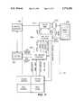
- FIG. 2is a block overview diagram of the system hardware and MPEG decoding unit hardware in accordance with the present invention.
- FIG. 3is a block diagram of the video bitstream DMA controller shown in FIG. 2.
- FIG. 4is a block diagram of the parsing unit shown in FIG. 2.
- FIG. 5Ais a block diagram of the interconnections of the zig-zagging unit, inverse discrete cosine transform unit, and motion compensation units shown in FIG. 2.
- FIG. 5Bis a block diagram of the de-zig-zag unit shown in FIG. 5A.
- FIG. 6Ais a block diagram of the inverse discrete cosine transform (IDCT) unit.
- FIG. 6Bis a flow diagram of the control logic process utilized in the IDCT unit shown in FIG. 6A.
- FIG. 6Cis a representation of the calculations performed by the IDCT circuit of FIG. 6A.
- FIG. 7is a logic diagram of the motion vector processor of the present system.
- FIG. 8is a block diagram of the macroblock configuration utilized in accordance with the present invention.
- FIG. 9is a table of the byte offsets for inserting the values from the macroblocks into the system memory.
- FIG. 10Ais a block diagram of the data pipe for the motion compensation unit of the present system.
- FIG. 10Bis an exemplary luminance and chrominance predictable macroblock.
- FIG. 11Ais a block diagram of the video output display functions in accordance with the system of the present invention.
- FIG. 11Bis a representation of the raster conversion of chroma data to YUV444 format.
- FIG. 11Cis a flowchart of the colorspace conversion matrix utilized in the CSC/dither circuit.
- FIG. 12is a process flow chart of a process for decoding a single MPEG data stream in accordance with the present invention.
- FIG. 13is a block diagram of the data flow between a host system memory and the MPEG decoding hardware in accordance with the present invention.
- FIG. 14is a flow chart indicating a multiple decode sequence for the method of decoding MPEG video data in accordance with the present invention.
- FIG. 15is a table showing the inputs and outputs of each block of data during a typical video sequence.
- the inventionprovides a flexible MPEG decoding system which is implemented in both hardware and software.
- a key aspect of the hardware and software system of the present inventionis the division of labor between decoding functions performed by the software and decoding functions performed by the hardware.
- Thisallows the MPEG decoding system of the present invention to be highly flexible, and with the proper instructions, to decode multiple MPEG streams, in effect, simultaneously.
- multi-threaded moving video, still images, and varied image sizescan be decoded by the system of the present invention.
- the hardware architectureallows all these situations to coexist with the software controlling distribution of image data, and sequencing of data to the hardware decoding functions.
- FIG. 1shows the breakdown of the division of labor between the hardware and software decoding functions of the system of the present invention.
- a typical video sequenceis broken down into a group of pictures, comprised of an I, P, and B-type pictures, which is comprised of slices of macroblocks, each macroblock containing an image block of 8 ⁇ 8 pixels and, possibly, encoded motion vector data.
- Line 30represents the division of labor between the software portion of the system and the hardware portion of the system.
- the software portion of the systemwill search the video sequence, determine the group of pictures ordering, and sequence the ordering of the pictures to be decoded to the hardware portion of the system.
- the hardware component of the systemdecodes image and motion vector information at the slice, macroblock, and block level in accordance with the MPEG-1 decoding standard and the following description.
- FIG. 2shows a general overview of the hardware components of a decoding system in accordance with the present invention.
- the hardware architecture of the present invention as shown in FIG. 2may reside in a host system, or be incorporated as part of an application specific integrated circuit (ASIC) 150 which is itself incorporated into a host system.
- the host systemwill include a system memory 110, a central processing unit (CPU) 102, an address and data bus 104, and a system memory controller 106.
- MPEG unit hardware control registers 112which are accessible to the CPU and decoding hardware, may be provided and include system status and configuration information.
- the control registers 112are configurable by the CPU 102 for use by the decoding system of the present invention. Such control registers are defined herein in conjunction with their function relative to given components.
- System memory 110generally comprises synchronous dynamic random access memory (SDRAM). As shown in FIG.
- MPEG decoding hardware 200may be included on ASIC 150.
- the host system or ASIC 150may include other hardware components for performing multimedia application specific processing such as, for example, digital signal processing, advanced video processing, and interfacing with other components of the host system.
- CPU 102may comprise a PowerPC class microprocessor manufactured by IBM Microelectronics and Motorola.
- System memory 110will contain MPEG-encoded video data which must be decoded by the MPEG decoding system in a coded data buffer.
- System memory 110is configured to include reference buffers, display (or “output") buffers, and a strip buffer which are accessible by decoding hardware 200 and the system CPU 102.
- a memory controller interface and arbiter 160handles all communication between system memory 110 and the MPEG decoding hardware 200.
- Memory controller interface 160will handle requests from a video bitstream DMA controller 170 which issues requests to read bitstream data into a buffer contained in the DMA controller 170; requests from a motion compensation unit 175 to read data into the motion compensation unit 175; requests from a video output DMA controller to write to the video output DMA controller 180; and read and write requests from a video output formatter 185.
- Arbitration between all the MPEG requestersis handled by memory controller 160.
- Memory controller 160can handle simultaneous, independent requests to several memory groups as discussed herein.
- Video bitstream DMA controller 170supplies coded data to the MPEG decoding unit 200.
- a FIFO unit in DMA controller 170contains data waiting to be transferred to a parsing unit 210, which is present in the MPEG decoding hardware 200.
- video bitstream DMA controller 170initiates memory requests to the memory arbiter 160 to refill the FIFO.
- MPEG decompression hardware 200performs the video decompression algorithm on the slice layer and below, including parsing of the video bitstream, entropy (Huffman or, more generally, variable length decoding (VLD)), inverse quantization, the inverse discrete cosine transform, and motion compensation.
- Three interfacesare provided to the MPEG decompression hardware 200: the coded data interface 202, the motion compensator interface 204, and the decoded data interface 206.
- Decoded data interface 202includes a data provision interface 202a, and a communication protocol interface 202b.
- Communication protocol interface 202butilizes a request/acknowledge protocol to communicate with the video bitstream DMA controller 170.
- MPEG core unit 200When decompressing predicted macroblocks, MPEG core unit 200, and specifically motion vector processor 212, supplies the pixel location of the prediction data in advance of the time the data is actually needed on line 204. Motion compensation unit 175 may then fetch the appropriate data from system memory 110. Decoded data comes out of port 206 in a block order, but without the zig-zag configuration. Five logical blocks are shown as comprising the MPEG core decoding hardware 200: the parsing unit 210, a motion vector processor 212, an inverse quantization unit 214, a "de-zig-zag unit” 216 and an inverse discrete cosine transform unit 218.
- Motion compensation unit 175converts pixel addresses of reference macroblocks supplied by the MPEG core hardware 200 to physical memory addresses in system memory 110 and initiates memory transactions with system memory 110 to acquire necessary data for motion compensation via the memory controller 160.
- the motion compensation unitwill perform half-pixel interpolation, if necessary, and store the prediction value in a local register until the corresponding pel is available at the output 206 of core hardware 200.
- the prediction data and the output of the core hardware 200(specifically IDCT 218) are combined by the motion compensator unit 175.
- the combined datamay be stored in a strip buffer by video output DMA controller 180. There is sufficient storage in the motion compensation unit 175 to ensure that no memory transaction has to be repeated during the duration of a macroblock.
- Video output DMA controller 180transfers decompressed data from the motion compensation unit 175 and the MPEG core hardware 200 to system memory 110.
- a buffer in the output DMA controller 180temporarily stores decompressed pixels on their way to system memory 110.
- the output DMA controllercalculates an address in system memory 110 where the data should be written and initiates the appropriate memory transaction via the memory controller interface 160.
- the DMA controllerpasses entire frames to the output formatter 185.
- Video output formatter 185converts images from the native MPEG format to one of several formats utilized by the host system. As discussed in further detail below, the output formatter contains a color space converter, dither circuit, and quantizer.
- the luminance/chrominance datais in a 4:4:4 format, it may also be directly passed to the output.
- the color space convertertransforms the MPEG data to the RGB (red/green/blue) domain for use in three-dimensional rendering.
- the quantizeroptionally converts 24 bit pixels to 16 bit pixels.
- control registers 112have a default configuration and may be configured by software instructions to CPU 102. Specific registers configured for functions of individual hardware elements are described in the following sections pertaining to such elements. Registers 112 are configured for system configurations and system interrupts as follows:
- FIG. 3is a hardware block diagram of the video bitstream DMA controller block 170 shown in FIG. 2.
- the bitstream DMA controller 170includes a 16 ⁇ 32 RAM 220, a multiplexer 222, a FIFO controller 224, and an address generator 226.
- Video bitstream DMA controller 170reads coded data from system memory 110 and places it into FIFO register 220. Generally, the parser unit 210 takes the data from the FIFO at a highly variable rate depending on the characteristics of the coded video bitstream.
- Coded data buffers (see FIG. 13) in system memory 110may begin on any byte boundary and may be any number of bytes long.
- DMA controller 170has its own queue of two address and length registers that tell it where in system memory 110 the coded data resides. Each time video bitstream DMA controller 170 exhausts a coded data buffer in main memory 110, it returns an interrupt to the CPU and begins reading coded data from the next valid address in the DMA controller queue of addresses.
- the queue of two buffer addressesis provided in a Current Address Register (Table 4) and a Next Address Register (Table 6) in DMA controller 170 and reduces the urgency of the end of buffer interrupt of DMA controller 170.
- Each buffer addressconsists of a (byte-aligned) memory address (Tables 4, 6) and a length in bytes (Tables 5, 7).
- the CPUTo place a buffer address in the queue, the CPU must first write a 23-bit physical memory address to the Next Address Register (Table 6) and then a 16-bit length to the Next Length Register (Table 7) in the DMA controller 170.
- the DMA controller 170optionally generates an interrupt, and moves on to the next buffer specified in the Next Address Register. After an end-of-picture interrupt is generated by the parsing unit 210, registers in the DMA controller 170 may be examined to determine where the first start code following the end-of-picture occurred.
- FIFO controller 224monitors the fullness of the 16 ⁇ 32 RAM 220 containing coded data on its way to parsing unit 220. Each time the data request from the parser unit 210 becomes valid, FIFO controller 224 moves on to the next 16 bits to be transferred.
- the memory address queueis provided in address generator 226 and is incremented every four bytes.
- FIFO controller 224makes a request to the address generator 226.
- Address generator 226initiates a memory transfer via memory controller 160. When the data becomes available, the address generator inserts a write signal to FIFO controller 224.
- a soft reset and enable for bitstream DMA controller 170are provided in the MPEG unit configuration register.
- a zero in the vbdReset bit locationdisables operation of the DMA controller 170; for normal operation, a "1" is written to this bit. If during normal operation, the bit transfers from a "1" to a zero, the DMA address queue is flushed and the remaining contents of the bitstream FIFO are immediately invalidated. Setting this bit to "0" is equivalent to a soft reset of the DMA controller 170.
- the vbdEnable bitis a bitstream enable bit, which, when disabled, pauses DMA controller 170.
- the DMA controller next address queueincludes a bitstream unit address queue control bit (Next Address) which, when written to, places a new value in the next location of the address queue. Note that the address does not become a valid entry in the queue until the corresponding write to the length register (Next Length) occurs.
- the addressis 25 bits long and the 25 bits uniquely specify a byte location in system memory 110. Any byte alignment is allowed. Registers implementing the address queue may be individually read via a direct memory mapping for diagnostic purposes.
- the bitstream unit current length queuecorresponds to the address queue (Video Bitstream DMA Current Address).
- Each entry in the lengthspecifies the number of bytes to be read from the segment of the bitstream beginning at the address contained in the corresponding entry of the address queue.
- Entries in the length queueare 16 bits long, allowing each buffer segment to be up to 64 Kbytes. Writing the length queue actually causes a new entry to be placed in the queue; a write to the address queue does not cause an update. Therefore, the address should be written before the length when adding a new segment to the length queue. If there are no valid addresses in the address queue, the address/length immediately becomes the current address for the DMA controller 170. If there is one valid address, the address length becomes the current value only after the buffer presently being read is exhausted.
- the Bitstream Unit DMA current status register of the DMA controllerallows the CPU to determine where in memory the DMA controller unit is currently reading from. This is particularly useful at the end of a picture in the case of a bitstream error.
- the MPEG core hardware 200is defined as the parsing unit 210, inverse quantization unit 214, motion vector processor 212, de-zig-zag unit 216, and inverse discrete cosine transform unit 218.
- parsing unit 210turns the MPEG bitstream (slice layer and below) into a series of motion vectors and run/level pairs that are passed on to the motion vector processor 212 and inverse quantization unit, respectively.
- the inverse quantization unitdecodes the run/level pairs (using Q-tables decoded from the bitstream by the system CPU 102), reconstructs the frequency domain discrete cosine transform samples as per the MPEG-1 specification, and passes them to the de-zig-zag unit 216.
- the de-zig-zag unitcontains memory to "de-zig-zag" the data recovered from the MPEG stream.
- the inverse discrete cosine transform unittransforms the frequency domain data into the spatial domain.
- Motion vectors from the parser unit 210are transferred to the motion vector processor 212.
- Motion compensation unit 175combines the prediction generated by the motion vector processor with the output from the inverse discrete cosine transform unit 218 and passes the results on to the video output DMA controller 180.
- FIG. 4shows a block diagram of the parsing unit 210 utilized in the MPEG core decompression hardware 200.
- Parser unit 210includes a bit shifter 230, parser state machine 232 and registers 234.
- the parsing unit 210must be programmed with the variables picture -- Coding -- Type, forward -- R -- Size and backward -- R -- Size as decoded from the bitstream by the CPU under the instructions provided in the system of the present invention. It should be recognized that these variables need not be present in a bitstream format, but can be decoded from coded data in a different data structure more suitably used for interactive formats.
- the following valuesreside in the parser configuration register set forth below:
- the parser configuration registercontains the reset and enable bits for the parser.
- the parser configuration registercontains parameters that must be decoded from the picture layer of the bitstream. This register is only written while the parser is in reset mode.
- the image size registerallows the parser to determine the relative addresses of the prediction of a predictive coded (p-picture) macroblock. It should only be modified while the parser is in reset.
- MPEG Specification 11172-2specifies the proper decoding of the variables mp -- height and mp -- width.
- the parser status registercontains information for the CPU from parser 210. It is utilized for debugging and retrieving details about bitstream errors by the CPU from parser 210.
- Parser state machine 232includes control logic 236 and a state register 238.
- Bit shifter 230also includes a register 231.
- the bit shifter 230shifts bitstream data up to 12 bit increments as defined by the control logic 236. As shown in Table 13, the control logic determines the amount of the shift necessary dependent upon the data being examined.
- the parserhandles elements in the bitstream as data units, such as the quantizer information, macroblock stuffing, address increment, etc.
- Table 14outlines the time necessary for each element to be handled by the parser. The amount of the bit shift allowed bit shifter 230 is directly dependent upon the data unit being handled.
- the control logicwill search the data for a start code in 12 bit increment shifts, 12 bits/clock cycle.
- Control logic 236determines the amount of the bit shift depending on the nature of the incoming data.
- the shift valueis written to the bit shift register 231.
- a start code in a video sequencecomprises 23 consecutive zeros.
- the bit shifterwill require 2 cycles, at 12 bits per cycle, to determine a start code.
- Table 13outlines the number of cycles (and the MPEG 1 specification the size and type of data) which the parser requires to examine incoming data.
- the parser configuration registers 234contain information derived from the stream header and allow the parser to determine the nature of the incoming data. Once the data type is determined, data can be shifted to the control logic which divides out the RLL and motion vector data to the IQ unit and the motion vector processor.
- the state register 238 in the parser state machine 232can track the data type expected by the control logic by reading the bit shift register 231.
- Parser unit 212directly detects certain error conditions. When the parser encounters an error, it generates an interrupt and freezes in its current state. The CPU can then examine the current state bits in the parser status register, and determine the type of error that caused the interrupt. The following table enumerates all of the detected error conditions and the state in which they are detected:
- a worst-case macroblock decodethe total number of cycles required would be 790 cycles.
- a worst-case macroblockwould consist of an address increment code with more than 4 bits, an M-quant, 2 motion vectors of the long variety, a long pattern code, an all-escape or long R/L pair codes. Macroblock stuffing and address escapes will add one cycle per instance to the worst case number.
- the inverse discrete transform unit 218can transform an entire macroblock in 1056 cycles, giving the parser approximately a 500 higher performance than the inverse discrete cosine transform unit. If macroblock stuffing is present, the parser's performance degrades; however, more than 300 stuffing codes would have to be inserted to lower the parser's performance to the level of the inverse discrete cosine transform unit.
- the inverse quantization unit 214decodes the run/length pairs and performs an inverse quantization on the incoming image blocks in accordance with the process outlined in the MPEG-1 specification.
- the inverse quantization unit 214contains a 128 bit long word space for reading and writing quantization tables in the IQ unit 214. As noted above, the quantization tables are decoded by the CPU 102 and provided to IQ unit 214. These tables should only be accessed while the IQ unit 214 is in re-set.
- FIG. 5Ashows the connections between the IDCT and the DZZ and motion compensation unit.
- DZZ 216includes a DZZ address generator, 64 ⁇ 12 RAM and flow control logic 256. Data from the IQ unit is written to RAM 254. Address generator 252 selects the data address for a data read so that data out of RAM 254 is in an inverse zig-zag format.
- the IDCT/DZZ handshaking interfaceconsists of the production of eight signals from the DZZ flow control 256 that indicate the availability of valid data (DZZ -- Validlines). Each signal corresponds to one of eight vertical columns that comprise an 8 ⁇ 8 block of samples. After reading the data from a particular column of samples in RAM 254, IDCT 218 inserts the corresponding signal in the IDCT -- invalidateDZZlines bus to inform DZZ 216 that the data has been read. DZZ 216 responds by lowering DZZ valid lines until the column contains new data.
- the DZZ data interfaceprovides a 6 bit read address from the IDCT 218 to the DZZ 216.
- the most significant 3 bitsselect the vertical column and the least significant bits select an individual sample within the column.
- the DZZ 216latches the address from the IDCT 218 and provides the selected data before the end of the next clock cycle.
- IDCT 218also provides an enable signal to allow power conservation of the random access memory within the DZZ.
- inverse discrete cosine transform (IDCT) unit 218transforms 8 ⁇ 8 blocks of frequency-domain input samples into 8 ⁇ 8 blocks of spatial domain pixels or differential pixels as specified in the MPEG-1 standard.
- the IDCT 218receives reconstructed frequency domain samples from DZZ 216, performs an inverse DCT to return the data to the spatial domain, and transfers the results to the motion compensator 175. Both interfaces to the IDCT 218 include handshaking. If data from DZZ 216 is unavailable, or the motion compensator 175 is not able to accept additional input, IDCT 218 will stall.
- the IDCT and motion compensator handshaking interfaceincludes a ready signal (MOT -- spaceavailable) from the motion compensator 175 to the IDCT 218.
- a ready signal(MOT -- spaceavailable) from the motion compensator 175 to the IDCT 218.
- Eight output valuescan be sent on the output data interface of IDCT 218.
- IDCT 218responds to the request by the motion compensator 175 by asserting the IDCT -- motAck to acknowledge that eight samples (comprising a horizontal row of pixels) will be available shortly.
- IDCT 218asserts IDCT -- dataOutValid when the samples actually appear at the output.
- the IDCT data interfaceconsists of a 9-bit, two's complement data bus (IDCT -- dataout) and a single bit data valid qualifier (IDCT -- dataOUTVALID).
- IDCT -- motAcka 9-bit, two's complement data bus
- IDCT -- dataOUTVALIDa single bit data valid qualifier
- the qualifier signalwill be asserted for eight consecutive cycles following each assertion of IDCT -- motAck.
- Each groupconsists of eight samples comprising a horizontal row of pixels (or differential pixel) outputs. The first group of eight corresponds to the uppermost row, and the outputs proceed downward to the bottom (8th) row of the macroblock. Within each row, the outputs occur in the following order, with zero as the leftmost output, 7 as the rightmost output: 0, 7, 3, 4, 1, 6, 2, 5. If mot -- spaceAvailable remains asserted, and the IDCT 218 input data is not started, the IDCT would produce one group of eight results every ten cycles.
- FIG. 6Ais a block diagram of the inverse discrete cosine transform unit.
- the inverse discrete cosine transform unittakes advantage of the separability of the discrete cosine transform unit by doing sixteen one-dimensional length eight inverse discrete transforms in order to calculate a single two-dimensional 8 ⁇ 8 inverse discrete cosine transform.
- Each one-dimensional inverse discrete cosine transformrequires ten cycles to execute.
- a single two-dimensional inverse discrete cosine transformcan be completed in 176 cycles per block or 1056 cycles per macroblock.
- the overall performance of the IDCT unitis thus 62,500 macroblocks per second at 66 Mhz.
- CCIR 601 videoconsists of 40,500 macroblocks per second, yielding more than 50% overhead above the CCIR 601 video rate. This allows for multiple threads of compressed data to essentially be decoded simultaneously.
- the IDCTcomprises control logic 300, a 64 ⁇ 18 CRAM 302, multiplexers 306-320, registers 322-334, multipliers 336-348, result registers 350-364, sine magnitude to two's-complement converters 365-372, adders 375-382, partial sum registers 384, 386, adder/subtracter 388, final result register 389, two's complement to sine-magnitude converter 390, rounding logic 392, rounded result register 394, clipper logic 396, sine-magnitude to two's complement converter 398, and IDCT -- dataout register 399.
- the DZZ -- DataOutis provided to multiplexer 304 and is distributed to seven multipliers 336-348 and multiplexers 308-320. Only seven multipliers are required as one multiplier MO is used twice (since its the result of which is equivalent to the result of M4).
- FIG. 6Cshows the multiplication ordering performed by the control logic for each of the eight iterations (0-7). Thus, the result of multiplier 336 is used in register 350 and register 352.
- the separability of the DCT transformallows the performance of 16 one dimensional length IDCTs in order to obtain the single, two-dimensional 8 ⁇ 8 IDCT.
- the IDCTmay not be halted in the middle of the computation of any one dimensional transform. It only stops after the transform has been completed, and either the motion compensation unit 175 is unable to accept new data or the DZZ cannot provide new input data.
- the IDCTwill produce eight results each time it goes through the main sequence of states. These results will either be placed into CRAM 302 for vertical iterations, or loaded into the motion compensator 175 for horizontal iterations.
- the IDCT control logic 300loads the proper inputs from the DZZ or CRAM 302 and operates multiplexers 308-320 to control signals in the data path to produce the desired result. Normally, the IDCT control logic 300 cycles through a sequence of 11 states, however, three conditions cause the sequence to vary: assertion of reset, lack of valid data in the DZZ, and lack of space available in the motion compensation unit.
- FIG. 6Bshows the possible states and transitions of the IDCT control logic state machine. The usual sequence of 11 states is shown in the center of the diagram, the reset/no data in the DZZ condition on the left and the motion compensator full state on the right.
- the control logicperforms eight horizontal and eight vertical iterations per two-dimensional IDCT.
- the iteration numberis maintained in a separate register.
- the MSB of the iteration registerdetermines whether a horizontal or vertical iteration is taking place. This is, in turn, used to create the read enable for the DZZ, write enable for the CRAM, and to make decisions the next state transition as outlined in FIG. 6B.
- the reset state of the control logicsets-up the first four multiplications necessary for calculation of the IDCT (LOAD -- F0, LOAD -- F4, LOAD -- F2 and LOAD -- F6).
- the normal 11 stages for the IDCTare LOAD -- F1, LOAD -- F3, LOAD -- F5 AND LOAD -- F7 to set up the multiplexers to calculate the multiplication ordering shown in FIG. 6C, then computation and storing stages COMPUTE -- R0 -- R7, RESULT -- R0 -- R7, COMPUTE -- R3 -- R4, RESULT -- R3 -- R4, COMPUTE -- R1 -- R6, RESULT -- R1 -- R6, and COMPUTE -- R2 -- R5.
- the control logicwill either loop to the LOAD -- F1 stage or store the COMPUTE -- R2 -- R5 result in RESULT -- R2 -- R5. If a vertical iteration is being performed and no preloading (DZZ -- validLines-valid) is occurring, or a horizontal iteration is occurring and space is available in the motion compensation unit (mot -- spaceAvailable), the LOAD -- F1 sequence will be executed.
- the IDCTproduces results during eight consecutive cycles out of 11 during normal operation. These eight cycles are qualified by the signal IDCT -- dataOutValid.
- FIG. 7is a block logic diagram of motion vector processor.
- the motion vector processor described with respect to FIG. 7implements the decoding of forward and backward motion vectors in accordance with the MPEG-1 specification.
- Motion vector processorreconstructs the value of the motion vectors in p-type and b-type macroblock pictures.
- the macroblocks motion vectorsare decoded in accordance with the standards set forth in the MPEG 1 standard.
- p-type macroblocksfirst the value of the forward motion vector for the macroblock is reconstructed and a prediction macroblock is formed. Then, the DCT coefficient information, stored for some or all of the blocks is decoded, dequantized, inverse DCT transformed and added, in motion compensation unit 180, to the prediction macroblock.
- the value of the forward motion vector for the macroblockis reconstructed from the retrieved forward motion vector information, and the backward motion vector for the macroblock is reconstructed from the retrieved backward motion vector information.
- the forward prediction and the backward predictionare then computed.
- the computed predictionis added to the differential pixels from the IDCT.
- motion vector processor 212horizontal and vertical motion vector data is input from the parser to a bit shifter 402. Shifter 402 is coupled to a forward/backward -- r -- size register (the forward/backward -- r -- size values being computed from the picture header information in accordance with the MPEG-1 standard) and the shift of bit register 402 is determined based on the input data. The data is then shifted to an intermediate result holding register 404.
- a forward/backward -- r -- size registerthe forward/backward -- r -- size values being computed from the picture header information in accordance with the MPEG-1 standard
- An overflow mask 410is also generated and comprises the r -- size shifted a quantity FFF (hex) to allow for checking of overflows in the picture boundary and allow the reference to "wrap" around picture boundaries.
- the reconstruction method implemented by motion vector processorbegins by generating a complement to the horizontal or vertical, forward or backward r -- values.
- a sign change control inputis provided to an exclusive-OR gate which has, as its other input, the data from register 404. The sign change is implemented dependent upon the values of the forward/backward -- r -- size, again in accordance with the MPEG-1 specification.
- the output of XOR gate 406is provided to an adder 408, which sums the output of XOR gate 406 with the previously retrieved values for the motion -- horizontal -- forward -- r, motion -- vertical -- forward -- r, motion -- horizontal -- backward -- r, and motion -- vertical -- backward -- r stored in registers 412-418 depending upon whether a horizontal or vertical motion vector is being processed.
- the output of adder 408is provided to OR gates 420,422 and AND gates 424, 426 along with mask 410 and the output of registers 412-418, and the output of a selector 428, which adds four to the value of the output from adder 408.
- the gate arrayperforms computation of the current motion vector being decoded based on the values in registers 412-418 and the input data.
- a multiplexerdetermines the proper result of the gate array output being decoded, i.e., the positive values for the reconstructed horizontal or vertical motion vectors (recon -- right, and recon -- down, respectively).
- the output of MUX 430is provided to a bit shifter 432 and second MUX 434.
- the final portion of the motion vector reconstructioninvolves computing the whole and half-pel unit values from the reconstructed values.
- the reconstructed values the half-pel valuesare selected by MUX 434 and stored in register 440.
- Adder 444sums the reconstructed value with a horizontal overhead selection value.
- Each macroblockis stored in memory as 384 continuous bytes. Organization within each macroblock is shown in FIG. 8. Each luminance block is divided into two halves, T for top and B for bottom. The chrominance blocks are divided into quarters numbered 0-3 from top to bottom. The offset of the first byte of each of these elements in the macroblock is given by the table in FIG. 9. The sort address for any macroblock is given by base+ (H) (16)H size +(V % 16)! ⁇ 384. This allows for easy calculation in hardware (since 384 is 3 ⁇ 128).
- the motion unit soft reset and enable bitsare present in the MPEG unit configuration register.
- the address for the reference buffers (Reference 0 and Reference 1) (shown in FIG. 10) in system memory 110must begin on a 4 KB boundary, giving 13 bits address for each buffer.
- the prediction addressshould be set to zero if the buffer is not present.
- FIG. 10Ashows the data pipe for the motion compensation unit utilized in the system of the present invention.
- the pipeconsists of a series of registers MUXs and adders which accept 32 byte data segments of prediction data in the order defined in an exemplary macroblock shown in FIG. 10B.
- the addresses of the prediction buffersare held in registers as shown in the following tables:
- Each scanis performed first for the forward prediction data, then for the backward prediction data.
- the pipefirst performs horizontal compensation in stages 500(0) through 500(8), then vertical compensation in steps 500(8a) through 500(9) as described further below.
- FIG. 10Bfour blocks comprising a single macroblock are shown for the luminance values. The following description will be limited to the luminance values, though it should be readily understood that the pipeline processing is similar for the chrominance blocks also shown in FIG. 10B.
- a worst case block predictionis shown at 460.
- the blockis not horizontally or vertically aligned with any block segment, and thus, to retrieve the eight 32 byte segments making up a single block, fifteen 32 byte segments (numbered 1-15) must be read, since data will be needed from each of these segments to interpolate the values for the selected block 460.
- Each segmentcontains four rows of eight pixels each. These rows are inserted into the pipeline as pixel words in the following order:
- dataenters the pipe in a series 32 bit registers 500(0-7) and is advanced register to register each clock tick.
- datais transferred sequentially through the registers to adders 502-508 which perform interpolation (if necessary) by averaging pixel data in adjacent 8-bit segments in register 500(7).
- adder 508is coupled to multiplexer 510 which has inputs from registers 500(0) and 500(6).
- the "right-most" byte of the even numbered wordsgets averaged with the "left-most" byte of the odd numbered words.
- the right-most of the odd wordsmust get averaged with the left-most of the corresponding even word in the adjacent chunk.
- registers 500(0) and 500(6)provide selectable outputs to MUX 510 which allow the control logic for the motion compensator to average byte neighbors within a word, and the right-most byte of each word with the left-most byte of either the 1-tick or 7-tick delayed word.
- MUXs 511-514allow for interpolation adders 502-508 to be bypassed when interpolation is not required (i.e., when the target block 460 is horizontally aligned within the luminance macroblock).
- a 36 bit wide register 500(8)stores the interpolated (or non-interpolated) horizontal data in four 9-bit banks. Truncation is performed on the horizontally interpolated data during vertical interpolation and the end pixels are eventually thrown out.
- a 16 ⁇ 36 RAM 515is provided to store the bottom row of each 32 byte segment and return it to the pipe at the proper instance.
- each pel's neighbor directly above itcan be found two clock ticks behind it in the data pipe.
- registers 500(8a) and 500(8b)are provided to delay the data by two clock ticks before vertical averaging.
- Register 500(9)stores the interpolation result in a 32 bit register. The data is still aligned in the same format it had in system memory, although interpolated.
- a MUX 450utilizes the lower few bits of the prediction address to move bytes horizontally and drop words vertically to shave off all but the prediction data. The horizontal swizzling requires that up to three bytes per row of each chunk be saved and joined with data from the next data segment. Thus a 24 bit wide 4 byte ⁇ 3 byte array of flip-flops 552 stores this information for rejoinder by MUXs 554-556.
- the pipeoutputs accurate predictions for either forward, reverse, or both motion vectors.
- the forward and reverse dataalternates with each row of data segments (4 pel rows) that come from memory.
- control instructionsensure that data is provided from the motion vector processor in the right order such that the if both the forward and reverse motion vectors are being predicted, the forward data never gets more than three pixel rows ahead of reverse and vice-versa. Tracking is performed to follow which prediction is ahead, and if data is received for the prediction that is ahead, it is stored in a second 16 ⁇ 32 RAM 560. If data is received for the trailing prediction, it can be interpolated with the data stored previously by adders 560-568 and MUXs 571-574.
- Register 500(B)holds the forward or reverse interpolated data.
- Chrominance datais placed into the pipe in a manner similar to luminance, except that the pipe must account for the interleaved structure.
- Horizontal half-pel interpolationis the same, except the vertical interpolation requires saving and restoring the last row of a block twice as often.
- the realignmentrequires setting the chroma prediction as only 8 ⁇ 8 ( ⁇ 2) and forward/reverse interpolation treats the component type as an additional row bit.
- the output DMA unit 180has two modes: a reference frame format and a strip buffer format. In reference frame format, all the output is written contiguously into reference frame format.
- a strip buffer(FIG. 13) is used in system memory when passing data to save memory when passing non-reference frames to the output formatter. Data is written in 16 KB programmable buffer in system memory 110 aligned on a 16K boundary.
- the following tablelists the output unit control registers:
- the allocated buffermust be large enough to hold at least two rows of macroblocks. This number must be rounded to the next highest power of two (32 KB for 352 pel wide video).
- a reference frame format with handshakingallows writing to a full reference from format in memory while performing output formatting at the same time.
- FIG. 11shows a block diagram of the video output formatter utilized in the system of the present invention.
- the video output formatteris operationally independent from the MPEG core hardware. This is another feature which allows multi-threaded decoding, since the core hardware may decode one stream while the formatter processes another.
- the output formatterincludes an input DMA interpolation raster 242, color space converter and dither filter 244, and a format conversion filter 246.
- the control registers set by CPU 102 in output formatter 185are set forth as follows:
- FIG. 11Adata from the output DMA controller is first converted to YUV444 format.
- FIG. 11Bgraphically represents the interpolation of the 4:2:2 data to 4:4:4 format by interpolation of the chroma pixels.
- the colorspace conversion and dither blockincludes adapted conversion coefficients to both convert and amplify the output values of the data.
- the color value conversion flowis represented in FIG. 11C.
- the YCbCr componentsare first normalized, and the RGB components then computed at step 482.
- the dithering matrix from Tables 22 and 23may then be applied.
- the format stage 246is controlled relative to the type of format the data is to be written to.
- Control bits for enabling the color space convertera video output format bit for controlling which output mode of two defined modes will be used (32 bit, 16 bit), and a dithering circuit enable are notably provided.
- a separate image size register(Table 25) allows the video output formatter to operate independently of the MPEG core hardware so decoding and formatting can occur simultaneously.
- FIGS. 12 and 13disclose the method of decoding an MPEG encoded video stream in accordance with the invention, and the data flow of video stream decompression in decompressing a single MPEG stream.
- the system instructionsprogram system memory buffers and the configuration register information is set at default. This includes the configuration register bit descriptions to allow the decoder system of the present invention to operate.
- a read of the compressed video stream from system memory 110occurs to determine, at step 264, context information from the video stream, including image size variables, and information for the parser unit 212 (including picture coding type, the forward R and backward R coding and size, the full pel backward vector, the macroblock width and the macroblock height).
- the context informationis programmed into the configuration registers of parser unit 220.
- the Q table valuesare determined and programmed in the registers of inverse quantization unit 222.
- the decoding of the picturesis determined and the slice information provided to coded data address locations in system memory 110 which are accessible by video bitstream DMA controller 170.
- the bitstream read addressesare written to the bitstream read address status registers.
- Steps 260 through 270complete the software instruction operations of the system of the present invention with respect to decoding the video bitstream.
- video bitstream DMA unit 170controls reads the encoded, macroblock-level data into the FIFO of the video bitstream DMA controller 170 in accordance with the description set forth above.
- parser unit 170parses the macroblock data into run level pairs for inverse quantization unit 214 and motion vector data for motion vector processor 212. Motion vectors are sent to the motion vector processor 212 at step 276 in FIG. 10.
- the inverse quantizer unit 214performs run level and Huffman decoding using the quantization tables provided at step 268.
- step 2828 ⁇ 8 DCT coefficient blocks provided from inverse quantization unit 214 are provided to de-zig-zag unit 216 and DCT coefficients data are provided to IDCT unit 218.
- step 284inverse discrete cosine transform unit 218 performs an inverse discrete cosine transform on the decoded data.
- motion compensation unitsums the motion prediction values and the IDCT decoded picture data by querying, when necessary, prediction reference data resident in the system memory, as will be explained with reference to FIG. 13.
- the decoded datais provided to the video output DMA control at step 292 and the video output formatter at step 294.
- FIG. 13represents a flow diagram of the data flow from specific locations in system memory 110 during video stream decompression.
- the system memoryis divided into five buffers: a coded data buffer, a strip buffer, two reference buffers (reference 0, reference 1), and two output buffers (output 0, output 1).
- Image data flowcomprises encoded data at the bitstream slice level, parsed in accordance with steps 260-270 of FIG. 10, provided to MPEG core unit 200 from system memory 110.
- Decoded datais returned to system memory 110, and specifically to a strip buffer utilized to hold the information prior to display.
- Decoded prediction data from motion vector processor(step 275) is also written to reference buffers 0 and 1, as represented along line 604, for use by motion compensation unit 179 relative to decoding P-picture and B-picture macroblocks.
- the decoded prediction data from reference buffers 0 and 1will, if necessary, be provided to motion compensation unit 175 as represented by line 606.
- reference buffer datamay also be used by the output formatter.
- the output of the video output formatteris provided to output buffers 1 and 2 as represented by line 612.
- System memory 110may include a series of output buffers, and a series of reference buffers, all which may be utilized in accordance with a one-to-one mapping of streams to reference buffer sets when the decoding hardware is decoding multiple streams of data.
- the reference buffersmay be implemented as a cache buffer system where the newest P- or B-picture reference information from several sequences is written into the section of the code (Reference 0 or 1) containing the oldest previously written P- or B- data. This reduces the system memory bandwidth required to implement the system of the present invention.
- FIG. 14A software sequence of a multiple threaded decoding algorithm is shown in FIG. 14.
- the sequence layer, group of pictures layer, and picture layermay be absent. Because multiple sequence headers, group of pictures headers, and picture reference information is included in the stream, random access into the video sequence is possible and indeed contemplated by the MPEG-1 standard. However, to achieve such random access, the MPEG-1 standard relies on repetition of the sequence header.
- each decoding sequence, at the video stream, group of pictures, picture or slice levelwill require execution of steps 260-264. Thus, steps 260-264, 260n-264n, and 260-264n+1 are shown for 3 streams.
- a decision at step 265is made by the control software dependent upon the nature of the display information being decoded. For example, if the information to be decoded is multiple small pixel array moving representations of baseball players on a field, decision step 265 would determine the ordering of decoding based upon the actions required of the players during the display. Thus, the specific criteria upon which ordering of streams occurs will be dependent upon the nature of the application being decoded, the information being displayed, the output format, and any number of other factors. Each stream from steps 266-264, 260n-264n, etc. may be selectively fed to the hardware processing steps 277-294. Because of the speed of the decoding hardware 200, an effective multiple-thread decode of image data is possible. In other words, multiple streams of data to be decoded could be provided to the decoding hardware for processing and, due to the speed of the hardware, each stream will be decoded and sent to system memory.
- FIG. 15shows the inputs and outputs of each block of data and the direction of each block of data during a typical video sequence.
- the diagramassumes the common IBBPBBPBBI type frame ordering.
- the input framesare shown in coded as opposed to temporal ordering.
- the rowsdetail the input and output of each of the hardware blocks as well as the contents of each buffer over time.
- an efficient, configurable, low-cost MPEG decoding systemis provided.
- the decoderutilizes a unique combination of hardware and software functions to decode an MPEG video stream.
- the systemallows decoding of multiple streams of MPEG video data.
Landscapes
- Engineering & Computer Science (AREA)
- Multimedia (AREA)
- Signal Processing (AREA)
- Compression Or Coding Systems Of Tv Signals (AREA)
Abstract
Description
TABLE 1 ______________________________________ MPEGUnit Configuration Register Bit Descriptions Name Bit(s) Type Description ______________________________________ (reserved) 0:18 x reserved vofRdEnable 19 RW output formatter read enable vofWrEnable 20 RW output formatter write enable vofReset.sub.-- n 21 RW output formatter reset vodEnable 22 RW Video Output DMA Enable vodReset.sub.-- n 23 RW Video OutputDMA Reset motEnable 24 RW Motion Estimator Enable motReset.sub.-- n 25 RW Motion Estimator Reset mvdReset.sub.-- n 26 RW Decompressor Reset parserStep 27 RW Parser Step Control parserEnable 28 RW Parser Enable parserReset.sub.-- n 29 RWParser Reset vbdEnable 30 RW Video Bitstream DMA Enable vbdReset.sub.-- n 31 RW Video Bitstream DMAReset ______________________________________
TABLE 2 ______________________________________ Interrupt Enable Name Bit(s) Type Description ______________________________________ (reserved) 0:24 x reserved Strip Buffer Error 25 RW error in output dma with strip buffer enabled Everything Done 26 RW output formatter, parser done Output Formatter 27 RW formatting complete Output DMA 28 RW DMA complete Bitstream Error 29 RW parser bitstream error End OfPicture 30 RW from parser Video Bitstream 31 RW buffer exhausted DMA ______________________________________
TABLE 3 ______________________________________ Interrupt Status Name Bit(s) Type Description ______________________________________ (reserved) 0:24 x reserved Strip Buffer Error 25 RW error in output dma with strip buffer enabled Everything Done 26 RW output formatter, parser done Output Formatter 27 R formatting complete Output DMA 28 R DMA complete Bitstream Error 29 R parser bitstream error End Of Picture 30 R from parser Video Bitstream 31 R buffer exhausted DMA ______________________________________
TABLE 4 ______________________________________ Bitstream Unit DMA Current Address Register Name Bit(s) Type Description ______________________________________ (reserved) 0:6 x reserved Current Address 7:31 R next read address ______________________________________
TABLE 5 ______________________________________ Video Bitstream DMA Current Length Name Bit(s) Type Description ______________________________________ (reserved) 0:14 x reserved Current Length 15:31 R bytes remaining in current buffer ______________________________________
TABLE 6 ______________________________________ Video Bitstream DMA Next Address Name Bit(s) Type Description ______________________________________ (reserved) 0:6 x reserved Next Address 7:31 RW next buffer address ______________________________________
TABLE 7 ______________________________________ Video Bitstream DMA Next Length Name Bit(s) Type Description ______________________________________ (reserved) 0:14 x reserved Next Length 15:31 RW next buffer length ______________________________________
TABLE 8 ______________________________________ Video Bitstream DMA Config/Status Name Bit(s) Type Description ______________________________________ (reserved) 0:14 x reserved vbd snoop enable 15 RW enable snooping on vbd reads (reserved) 16:26 x reserved Buffer Byte Count 27:31 R number of bytes buffered ______________________________________
TABLE 9 ______________________________________ Parser Configuration Name Bit(s) Type Description ______________________________________ (reserved) 0:2 x reserved full.sub.-- pel.sub.-- backward.sub.-- 3 RW from picture header vector (reserved) 4 x reserved backward.sub.-- r.sub.-- size 5:7 RW from picture header (reserved) 8:10 x reserved full.sub.-- pel.sub.-- forward.sub.-- 11 RW from picture header vector (reserved) 12 x reserved forward.sub.-- r.sub.-- size 13:15 RW from picture header (reserved) 16 x reserved priorityMode 17:19 RW priority request control (reserved) 20:28 x reserved picture.sub.-- coding.sub.-- type 29:31 RW from picture header ______________________________________
TABLE 10 ______________________________________ Image Size Name Bit(s) Type Description ______________________________________ (reserved) 0:15 x reserved mb.sub.-- height 16:23 RW image width in macroblocks mb.sub.-- width 24:31 RW image height in macroblocks ______________________________________
TABLE 11 ______________________________________Parser Status 0 Name Bit(s) Type Description ______________________________________ (reserved) 0 x reserved mb.sub.-- row 1:7 R current macroblock row (reserved) 8 x reserved bitstreamError 9R 1 = bitstream error detected error state 10:15 R state where error occurred eval bits 15:31 R current bit shifter output ______________________________________
TABLE 12 ______________________________________Parser Status 1 Name Bit(s) Type Description ______________________________________ (reserved) 0:2 x reserved blockNumber 3:5 R current block number macroblock.sub.-- type 6:10 R as in MPEG spec numBits Valid 11:15 R # of valid eval bits, from left lastStartCode 16:23 R last start code parsed (reserved) 24 x reserved mb.sub.-- column 25:31 R current macroblock column ______________________________________
TABLE 13 ______________________________________ Parser Performance Decoding Process Performance ______________________________________ Look forslice header 12 bits/cycle Quantizer Scale 1 tick SliceExtra Information 1 cycle if none present, 1 cycle per code otherwiseMacroblock Stuffing 1 cycle if none present, 1 cycle per code otherwise Macroblock Address Incre- 1 cycle for codes less than 4 bits, 2 cycles ment for longer codes, plus 1 cycle for eachescape Macroblock Type 1cycle Motion Vectors 1 cycle for each vector not present; otherwise; 1 cycle for the motion code if less than 4 bits, 2 cycles otherwise; plus 1 cycle if R present --times 2 to account for both H andV Macroblock Pattern 1 cycle, whether present or not; 2 cycles for codes longer than 4 bits Block There is a 1 cycle overhead at the beginning of each block while the parser decides what to do next DC Term in I-coded 3 cycles Macroblocks Each R/L Code (including 1 cycle if code less than 4 bits, 2 cycles first in non-I-coded Macro- otherwise blocks) Each R/L Escape 2 cycles End ofMacroblock 1 cycle ______________________________________
TABLE 14 ______________________________________ Parser State Table State Number Symbolic State Name (decimal) Description of Error ______________________________________ HANDLE.sub.-- START.sub.-- CODE 9 Invalid slice start code (>mb.sub.-- height) QUANTIZER.sub.-- SCALE 10 Quantizer.sub.-- scale set to zero MACROBLOCK.sub.-- ADDRESS.sub.-- 13 Invalid VLC for INCREMENT macroblock address increment MACROBLOCK.sub.-- ADDRESS 14 Invalid macroblock.sub.-- address.sub.-- increment after a slice start code (>mb.sub.-- width) -- or -- decoded macroblock.sub.-- address.sub.-- increment causes decoding to go beyond the end of the picture (as defined by mb.sub.-- height and mb.sub.-- width) MACROBLOCK.sub.-- TYPE 15 Invalid macroblock type VLC QUANTIZER.sub.-- SCALE.sub.-- MB 16 Quantizer.sub.-- scale set to zero MOTION.sub.-- CODE 18 Invalid motion VLC MACROBLOCK.sub.-- PATTERN 20 Invalid coded.sub.-- block.sub.-- pattern VLC DCT.sub.-- DC.sub.-- SIZE.sub.-- 22 Invalid VLC for LUMINANCE dct.sub.-- dc.sub.-- size.sub.-- luminance DCT.sub.-- DC.sub.-- SIZE.sub.-- 23 Invalid VLC for CHROMINANCE dct.sub.-- dc.sub.-- size.sub.-- chrominance DO.sub.-- RUN 27 More than 64 samples decoded for one block DECODE.sub.-- RLP.sub.-- STAGE1 32 Invalid run/level VLC -- or more than 64 samples decoded for one block DECODE.sub.-- RLP.sub.-- STAGE2 33 Invalid run/level VLC -- or more than 64 samples decoded for one block DECODE.sub.-- RLP.sub.-- ESCAPE.sub.-- 35 More than 64 samples LEVEL decoded for one block DECODE.sub.-- RLP.sub.-- ESCAPE.sub.-- 36 More than 64 samples LONG decoded for one block END.sub.-- OF.sub.-- SLICE 30 More than 12 consecutive zeros found that are not followed by a valid start code ______________________________________
TABLE 15 ______________________________________ Forward Prediction Buffer Address Name Bit(s) Type Description ______________________________________ (reserved) 0:6 x reserved forward prediction 7:19 RW 4K aligned address buffer address (reserved) 20:31 x reserved ______________________________________
TABLE 16 ______________________________________ Reverse Prediction Buffer Address Name Bit(s) Type Description ______________________________________ (reserved) 0:6 x reserved reverse prediction 7:19 RW 4K aligned address buffer address (reserved) 20:31 x reserved ______________________________________
______________________________________ column 0 1 ______________________________________row 0 0 1row 1 2 3row 2 4 5row 3 6 7 ______________________________________
______________________________________ A0 A1 B0 B1 A2 A3 B2 B3 A4 A5 B4 B5 A6 A7 B6 B7 ______________________________________
TABLE 17 ______________________________________ Output Control Register Name Bit(s) Description ______________________________________ Output Address 19:31 Physical base address of reference frame being written RFU 16:18Output Mode 15 OXX -- Reference frame format; XOX -- Reference frame format with handshaking 100 -- 16 KB Strip; 101 -- 32 KB Strip; 110 -- 64 KB Strip; 111 -- 128 KB Strip RFU 0:13 ______________________________________
TABLE 18 ______________________________________ Output Formatter Configuration Name Bit(s) Type Description ______________________________________ (reserved) 0:2 x reserved vof snoop enable 3 RW enable snooping on vof output (reserved) 4:6 x reserved (reserved) 4:9 x reservedformat 11RW 0 = 32bit 1 = 16 bit (reserved) 16:18 x reserved enable CSC 19 RW YCbCr → RGB conversion on (reserved) 20:22 x reserved rowChunks 23:31 RW number of 32B chunks per line ______________________________________
TABLE 19 ______________________________________ Output Formatter Cropping Control Name Bit(s) Type Description ______________________________________ (reserved) 0 x reserved hStart 1:7 RW starting horizontal MB offset (reserved) 8 x reserved vStart 9:15 RW starting vertical MB offset (reserved) 16 x reserved hStop 17:23 RW ending horizontal MB offset (reserved) 24 x reserved vStop 25:31 RW ending vertical MB offset ______________________________________
TABLE 20 ______________________________________ Output Formatter Input Buffer Address Name Bit(s) Type Description ______________________________________ (reserved) 0:6 x reserved unformatted display 7:19 RW 4K aligned address buffer address (reserved) 20:31 x reserved ______________________________________
TABLE 21 ______________________________________ Output Formatter Output Buffer Address Name Bit(s) Type Description ______________________________________ (reserved) 0:6 x reserved formatted display 7:26 RW 32B aligned address buffer address (reserved) 27:31 x reserved ______________________________________
TABLE 22 ______________________________________ Dither Matrix, Upper Half Name Bit(s) Type Description ______________________________________ dither matrix (0,0) 0:3 RW signed 4-bit error value dither matrix (0,1) 4:7 RW (set to 0 for no dithering) dither matrix (0,2) 8:11 RW . . . dither matrix (0,3) 12:15 RW . . . dither matrix (1,0) 16:19 RW . . . dither matrix (1,1) 20:23 RW . . . dither matrix (1,2) 24:27 RW . . . dither matrix (1,3) 28:31 RW . . . through (1,3) ______________________________________
TABLE 23 ______________________________________ Dither Matrix, Lower Half Name Bit(s) Type Description ______________________________________ dither matrix (2,0) 0:3 RW signed 4-bit error value dither matrix (2,1) 4:7 RW (set to 0 for no dithering) dither matrix (2,2) 8:11 RW . . . dither matrix (2,3) 12:15 RW . . . dither matrix (3,0) 16:19 RW . . . dither matrix (3,1) 20:23 RW . . . dither matrix (3,2) 24:27 RW . . . dither matrix (3,3) 28:31 RW . . . through (3,3) ______________________________________
TABLE 24 ______________________________________ Output Formatter Alpha Fill Value Name Bit(s) Type Description ______________________________________ (reserved) 0:23 x reservedDSB 24 RW control bit alpha fill value 25:31 RW 7-bit alpha channel fill value ______________________________________
TABLE 25 ______________________________________ Output Formatter Image Size Name Bit(s) Type Description ______________________________________ (reserved) 0:15 x reserved mb.sub.-- height 16:23 RW image width in macroblocks mb.sub.-- width 24:31 RW image height in macroblocks ______________________________________
Claims (17)
Priority Applications (1)
| Application Number | Priority Date | Filing Date | Title |
|---|---|---|---|
| US08/769,575US5774206A (en) | 1995-05-10 | 1996-12-19 | Process for controlling an MPEG decoder |
Applications Claiming Priority (2)
| Application Number | Priority Date | Filing Date | Title |
|---|---|---|---|
| US43908595A | 1995-05-10 | 1995-05-10 | |
| US08/769,575US5774206A (en) | 1995-05-10 | 1996-12-19 | Process for controlling an MPEG decoder |
Related Parent Applications (1)
| Application Number | Title | Priority Date | Filing Date |
|---|---|---|---|
| US43908595AContinuation | 1995-05-10 | 1995-05-10 |
Publications (1)
| Publication Number | Publication Date |
|---|---|
| US5774206Atrue US5774206A (en) | 1998-06-30 |
Family
ID=23743227
Family Applications (1)
| Application Number | Title | Priority Date | Filing Date |
|---|---|---|---|
| US08/769,575Expired - LifetimeUS5774206A (en) | 1995-05-10 | 1996-12-19 | Process for controlling an MPEG decoder |
Country Status (1)
| Country | Link |
|---|---|
| US (1) | US5774206A (en) |
Cited By (53)
| Publication number | Priority date | Publication date | Assignee | Title |
|---|---|---|---|---|
| US5920353A (en)* | 1996-12-03 | 1999-07-06 | St Microelectronics, Inc. | Multi-standard decompression and/or compression device |
| US5923375A (en)* | 1996-02-27 | 1999-07-13 | Sgs-Thomson Microelectronics S.R.L. | Memory reduction in the MPEG-2 main profile main level decoder |
| US5963222A (en)* | 1997-10-27 | 1999-10-05 | International Business Machines Corporation | Multi-format reduced memory MPEG decoder with hybrid memory address generation |
| WO2000026820A1 (en)* | 1998-10-30 | 2000-05-11 | Intel Corporation | Managing entertainment system data |
| US6072832A (en)* | 1996-10-25 | 2000-06-06 | Nec Corporation | Audio/video/computer graphics synchronous reproducing/synthesizing system and method |
| US6111915A (en)* | 1997-03-24 | 2000-08-29 | Oki Electric Industry Co., Ltd. | Picture decoder |
| US6160915A (en)* | 1996-11-07 | 2000-12-12 | Sony Corporation | Coded signal transmission method and apparatus |
| US6172740B1 (en) | 1998-07-01 | 2001-01-09 | Canon Kabushiki Kaisha | Projection exposure apparatus and device manufacturing method |
| US6175592B1 (en)* | 1997-03-12 | 2001-01-16 | Matsushita Electric Industrial Co., Ltd. | Frequency domain filtering for down conversion of a DCT encoded picture |
| US6275618B1 (en)* | 1996-08-14 | 2001-08-14 | Sony Corporation | Apparatus for and method of processing images |
| US6298087B1 (en)* | 1998-08-31 | 2001-10-02 | Sony Corporation | System and method for decoding a variable length code digital signal |
| EP1009169A3 (en)* | 1998-12-08 | 2002-03-06 | STMicroelectronics, Inc. | System, method and apparatus for an instruction driven digital video processor |
| US20020041714A1 (en)* | 2000-09-22 | 2002-04-11 | Takanori Ishida | Image decoding apparatus, image decoding method, and program storage medium |
| US6408436B1 (en) | 1999-03-18 | 2002-06-18 | Next Level Communications | Method and apparatus for cross-connection of video signals |
| US20020141496A1 (en)* | 2001-03-30 | 2002-10-03 | Koninklijke Philips Electronics N.V. | MPEG-2 decoder with an embedded contrast enhancement function and methods therefor |
| US20030009524A1 (en)* | 2001-06-02 | 2003-01-09 | Michael Kenoyer | System and method for point to point integration of personal computers with videoconferencing systems |
| US20030152282A1 (en)* | 2002-02-12 | 2003-08-14 | International Business Machines Corporation | Method, system, and program for fractionally shifting data subject to a previous transformation |
| US6625320B1 (en)* | 1997-11-27 | 2003-09-23 | British Telecommunications Public Limited Company | Transcoding |
| US6631164B1 (en)* | 1998-12-22 | 2003-10-07 | Thomson Licensing S.A. | Addressing process for the storage of image blocks |
| US20040052507A1 (en)* | 2001-11-06 | 2004-03-18 | Satoshi Kondo | Moving picture coding method and moving picture decoding method |
| EP1009170A3 (en)* | 1998-12-08 | 2004-04-14 | STMicroelectronics, Inc. | System, method and apparatus for a variable output video decoder |
| US20050036555A1 (en)* | 2003-08-13 | 2005-02-17 | Lakshmanan Ramakrishnan | Automatic direct memory access engine |
| US20050047510A1 (en)* | 2003-08-27 | 2005-03-03 | Muneaki Yamaguchi | Data processing device for MPEG |
| US20050168470A1 (en)* | 2004-01-30 | 2005-08-04 | Ram Prabhakar | Variable-length coding data transfer interface |
| US20050262276A1 (en)* | 2004-05-13 | 2005-11-24 | Ittiam Systamc (P) Ltd. | Design method for implementing high memory algorithm on low internal memory processor using a direct memory access (DMA) engine |
| US20060153303A1 (en)* | 2005-01-11 | 2006-07-13 | Hsu Jung-Fu | Apparatus and method for video decoding |
| KR100636110B1 (en)* | 1999-10-29 | 2006-10-18 | 삼성전자주식회사 | Terminal that supports MPEG-4 transmission and reception signaling |
| US20070053444A1 (en)* | 2003-05-14 | 2007-03-08 | Shojiro Shibata | Image processing device and image processing method, information processing device and information processing method, information recording device and information recording method, information reproducing device and information reproducing method, storage medium, and program |
| US20070120711A1 (en)* | 2005-11-28 | 2007-05-31 | Conexant Systems, Inc. | Decoding systems and methods |
| US20070160151A1 (en)* | 2003-11-26 | 2007-07-12 | Stmicroelectronics Limited | Video decoding device |
| US20070253488A1 (en)* | 1999-02-09 | 2007-11-01 | Takuya Kitamura | Coding system and method, encoding device and method, decoding device and method, recording device and method, and reproducing device and method |
| US20080013625A1 (en)* | 1998-03-10 | 2008-01-17 | Katsumi Tahara | Transcoding system using encoding history information |
| US7321368B2 (en)* | 1996-08-26 | 2008-01-22 | Stmicroelectronics, Inc. | Electronic system and method for display using a decoder and arbiter to selectively allow access to a shared memory |
| US20080123748A1 (en)* | 2002-03-18 | 2008-05-29 | Stmicroelectronics Limited | Compression circuitry for generating an encoded bitstream from a plurality of video frames |
| USRE40415E1 (en)* | 1994-03-29 | 2008-07-01 | Sony Corporation | Picture signal transmitting method and apparatus |
| US20080273804A1 (en)* | 2007-05-02 | 2008-11-06 | Motorola, Inc. | Image Transformation |
| CN101310538A (en)* | 2005-12-30 | 2008-11-19 | 英特尔公司 | Hardware motion compensation for video decoding |
| US20080317138A1 (en)* | 2007-06-20 | 2008-12-25 | Wei Jia | Uniform video decoding and display |
| US20090074314A1 (en)* | 2007-09-17 | 2009-03-19 | Wei Jia | Decoding variable lenght codes in JPEG applications |
| US20090073007A1 (en)* | 2007-09-17 | 2009-03-19 | Wei Jia | Decoding variable length codes in media applications |
| US20090141996A1 (en)* | 2007-12-03 | 2009-06-04 | Wei Jia | Comparator based acceleration for media quantization |
| US20090141797A1 (en)* | 2007-12-03 | 2009-06-04 | Wei Jia | Vector processor acceleration for media quantization |
| US20090141032A1 (en)* | 2007-12-03 | 2009-06-04 | Dat Nguyen | Synchronization of video input data streams and video output data streams |
| US20090190829A1 (en)* | 2003-07-18 | 2009-07-30 | Sony Corporation | Image decoding apparatus and method for handling intra-image predictive decoding with various color spaces and color signal resolutions |
| US20090257509A1 (en)* | 2008-04-11 | 2009-10-15 | Sony Corporation | Information processing system and information processing method, and program |
| US20100150244A1 (en)* | 2008-12-11 | 2010-06-17 | Nvidia Corporation | Techniques for Scalable Dynamic Data Encoding and Decoding |
| US20120243610A1 (en)* | 2005-09-20 | 2012-09-27 | Rahul Saxena | Dynamically configuring a video decoder cache for motion compensation |
| US8726125B1 (en) | 2007-06-06 | 2014-05-13 | Nvidia Corporation | Reducing interpolation error |
| US8725504B1 (en) | 2007-06-06 | 2014-05-13 | Nvidia Corporation | Inverse quantization in audio decoding |
| US20140161172A1 (en)* | 2012-12-11 | 2014-06-12 | Jason N. Wang | Software hardware hybrid video encoder |
| US20160366419A1 (en)* | 2002-04-26 | 2016-12-15 | Sony Corporation | Encoding device and method, decoding device and method, editing device and method, recording medium, and program |
| US10419021B2 (en) | 2000-10-03 | 2019-09-17 | Realtime Data, Llc | Systems and methods of data compression |
| USRE48845E1 (en) | 2002-04-01 | 2021-12-07 | Broadcom Corporation | Video decoding system supporting multiple standards |
Citations (10)
| Publication number | Priority date | Publication date | Assignee | Title |
|---|---|---|---|---|
| US5227878A (en)* | 1991-11-15 | 1993-07-13 | At&T Bell Laboratories | Adaptive coding and decoding of frames and fields of video |
| US5262854A (en)* | 1992-02-21 | 1993-11-16 | Rca Thomson Licensing Corporation | Lower resolution HDTV receivers |
| US5379351A (en)* | 1992-02-19 | 1995-01-03 | Integrated Information Technology, Inc. | Video compression/decompression processing and processors |
| US5379356A (en)* | 1991-03-15 | 1995-01-03 | C-Cube Microsystems | Decompression processor for video applications |
| US5379070A (en)* | 1992-10-02 | 1995-01-03 | Zoran Corporation | Parallel encoding/decoding of DCT compression/decompression algorithms |
| US5461679A (en)* | 1991-05-24 | 1995-10-24 | Apple Computer, Inc. | Method and apparatus for encoding/decoding image data |
| US5502494A (en)* | 1993-10-25 | 1996-03-26 | Lsi Logic Corporation | Management of channel buffer in video decoders |
| US5508942A (en)* | 1993-11-24 | 1996-04-16 | Intel Corporation | Intra/inter decision rules for encoding and decoding video signals |
| US5510842A (en)* | 1994-05-04 | 1996-04-23 | Matsushita Electric Corporation Of America | Parallel architecture for a high definition television video decoder having multiple independent frame memories |
| US5510841A (en)* | 1991-09-20 | 1996-04-23 | Sony Corporation | Encoding apparatus in which flat subblocks are identified in blocks of a motion signal prior to coding the blocks and complementary decoding apparatus |
- 1996
- 1996-12-19USUS08/769,575patent/US5774206A/ennot_activeExpired - Lifetime
Patent Citations (12)
| Publication number | Priority date | Publication date | Assignee | Title |
|---|---|---|---|---|
| US5379356A (en)* | 1991-03-15 | 1995-01-03 | C-Cube Microsystems | Decompression processor for video applications |
| US5461679A (en)* | 1991-05-24 | 1995-10-24 | Apple Computer, Inc. | Method and apparatus for encoding/decoding image data |
| US5510841A (en)* | 1991-09-20 | 1996-04-23 | Sony Corporation | Encoding apparatus in which flat subblocks are identified in blocks of a motion signal prior to coding the blocks and complementary decoding apparatus |
| US5512952A (en)* | 1991-09-20 | 1996-04-30 | Sony Corporation | Picture signal encoding and/or decoding apparatus |
| US5227878A (en)* | 1991-11-15 | 1993-07-13 | At&T Bell Laboratories | Adaptive coding and decoding of frames and fields of video |
| US5379351A (en)* | 1992-02-19 | 1995-01-03 | Integrated Information Technology, Inc. | Video compression/decompression processing and processors |
| US5262854A (en)* | 1992-02-21 | 1993-11-16 | Rca Thomson Licensing Corporation | Lower resolution HDTV receivers |
| US5379070A (en)* | 1992-10-02 | 1995-01-03 | Zoran Corporation | Parallel encoding/decoding of DCT compression/decompression algorithms |
| US5502494A (en)* | 1993-10-25 | 1996-03-26 | Lsi Logic Corporation | Management of channel buffer in video decoders |
| US5508942A (en)* | 1993-11-24 | 1996-04-16 | Intel Corporation | Intra/inter decision rules for encoding and decoding video signals |
| US5511003A (en)* | 1993-11-24 | 1996-04-23 | Intel Corporation | Encoding and decoding video signals using spatial filtering |
| US5510842A (en)* | 1994-05-04 | 1996-04-23 | Matsushita Electric Corporation Of America | Parallel architecture for a high definition television video decoder having multiple independent frame memories |
Non-Patent Citations (4)
| Title |
|---|
| C Cube Microsystems Product Catalog, pp. 9 36, 91 112, Fall 1994.* |
| C-Cube Microsystems Product Catalog, pp. 9-36, 91-112, Fall 1994. |
| Information Technology Coding of moving pictures and associated audio for digital storage media at up to about 1,5 Mbit/s Part 2: Video, First Edition 1993 08 01, ISO/IEC Joint Technical Committee, No. 11172 2.* |
| Information Technology -Coding of moving pictures and associated audio for digital storage media at up to about 1,5 Mbit/s -Part 2: Video, First Edition 1993-08-01, ISO/IEC Joint Technical Committee, No. 11172-2. |
Cited By (144)
| Publication number | Priority date | Publication date | Assignee | Title |
|---|---|---|---|---|
| USRE43238E1 (en) | 1994-03-29 | 2012-03-13 | Sony Corporation | Picture signal transmitting method and apparatus |
| USRE43021E1 (en) | 1994-03-29 | 2011-12-13 | Sony Corporation | Picture signal transmitting method and apparatus |
| USRE43111E1 (en) | 1994-03-29 | 2012-01-17 | Sony Corporation | Picture signal transmitting method and apparatus |
| USRE40415E1 (en)* | 1994-03-29 | 2008-07-01 | Sony Corporation | Picture signal transmitting method and apparatus |
| USRE43043E1 (en) | 1994-03-29 | 2011-12-27 | Sony Corporation | Picture signal transmitting method and apparatus |
| US5923375A (en)* | 1996-02-27 | 1999-07-13 | Sgs-Thomson Microelectronics S.R.L. | Memory reduction in the MPEG-2 main profile main level decoder |
| US6275618B1 (en)* | 1996-08-14 | 2001-08-14 | Sony Corporation | Apparatus for and method of processing images |
| US7321368B2 (en)* | 1996-08-26 | 2008-01-22 | Stmicroelectronics, Inc. | Electronic system and method for display using a decoder and arbiter to selectively allow access to a shared memory |
| US20100309211A1 (en)* | 1996-08-26 | 2010-12-09 | Stmicroelectronics, Inc. | Electronic system and method for selectively allowing access to a shared memory |
| US8314808B2 (en) | 1996-08-26 | 2012-11-20 | Stmicroelectronics, Inc. | Electronic system and method for selectively allowing access to a shared memory |
| US8054315B2 (en) | 1996-08-26 | 2011-11-08 | Stmicroelectronics, Inc. | Electronic system and method for selectively allowing access to a shared memory |
| US8681164B2 (en) | 1996-08-26 | 2014-03-25 | Stmicroelectronics, Inc. | Electronic system and method for selectively allowing access to a shared memory |
| US20090201305A1 (en)* | 1996-08-26 | 2009-08-13 | Stmicroelectronics, Inc. | Electronic system and method for selectively allowing access to a shared memory |
| US7898548B2 (en) | 1996-08-26 | 2011-03-01 | Stmicroelectronics, Inc. | Electronic system and method for selectively allowing access to a shared memory |
| US20110122946A1 (en)* | 1996-08-26 | 2011-05-26 | Stmicroelectronics, Inc. | Electronic system and method for selectively allowing access to a shared memory |
| US7542045B2 (en) | 1996-08-26 | 2009-06-02 | Stmicroelectronics, Inc. | Electronic system and method for display using a decoder and arbiter to selectively allow access to a shared memory |
| US7777753B2 (en) | 1996-08-26 | 2010-08-17 | Stmicroelectronics, Inc. | Electronic system and method for selectively allowing access to a shared memory |
| US20080088637A1 (en)* | 1996-08-26 | 2008-04-17 | Stmicroelectronics, Inc. | Electronic system and method for display using a decoder and arbiter to selectively allow access to a shared memory |
| US6072832A (en)* | 1996-10-25 | 2000-06-06 | Nec Corporation | Audio/video/computer graphics synchronous reproducing/synthesizing system and method |
| USRE39345E1 (en)* | 1996-10-25 | 2006-10-17 | Nec Corporation | Audio/Video/Computer graphics synchronous reproducing/synthesizing system and method |
| US6160915A (en)* | 1996-11-07 | 2000-12-12 | Sony Corporation | Coded signal transmission method and apparatus |
| US5920353A (en)* | 1996-12-03 | 1999-07-06 | St Microelectronics, Inc. | Multi-standard decompression and/or compression device |
| US6175592B1 (en)* | 1997-03-12 | 2001-01-16 | Matsushita Electric Industrial Co., Ltd. | Frequency domain filtering for down conversion of a DCT encoded picture |
| US6111915A (en)* | 1997-03-24 | 2000-08-29 | Oki Electric Industry Co., Ltd. | Picture decoder |
| US5963222A (en)* | 1997-10-27 | 1999-10-05 | International Business Machines Corporation | Multi-format reduced memory MPEG decoder with hybrid memory address generation |
| US6625320B1 (en)* | 1997-11-27 | 2003-09-23 | British Telecommunications Public Limited Company | Transcoding |
| US8687690B2 (en) | 1998-03-10 | 2014-04-01 | Sony Corporation | Transcoding system using encoding history information |
| US20080013627A1 (en)* | 1998-03-10 | 2008-01-17 | Katsumi Tahara | Transcoding system using encoding history information |
| US20080013625A1 (en)* | 1998-03-10 | 2008-01-17 | Katsumi Tahara | Transcoding system using encoding history information |
| US8638849B2 (en) | 1998-03-10 | 2014-01-28 | Sony Corporation | Transcoding system using encoding history information |
| US6172740B1 (en) | 1998-07-01 | 2001-01-09 | Canon Kabushiki Kaisha | Projection exposure apparatus and device manufacturing method |
| US6298087B1 (en)* | 1998-08-31 | 2001-10-02 | Sony Corporation | System and method for decoding a variable length code digital signal |
| US7058635B1 (en) | 1998-10-30 | 2006-06-06 | Intel Corporation | Method and apparatus for searching through an electronic programming guide |
| WO2000026820A1 (en)* | 1998-10-30 | 2000-05-11 | Intel Corporation | Managing entertainment system data |
| US6947485B2 (en) | 1998-12-08 | 2005-09-20 | Stmicroelectronics, Inc. | System, method and apparatus for an instruction driven digital video processor |
| EP1009170A3 (en)* | 1998-12-08 | 2004-04-14 | STMicroelectronics, Inc. | System, method and apparatus for a variable output video decoder |
| EP1715696A3 (en)* | 1998-12-08 | 2008-03-19 | STMicroelectronics, Inc. | System, method and apparatus for a variable output video decoder |
| US6414996B1 (en) | 1998-12-08 | 2002-07-02 | Stmicroelectronics, Inc. | System, method and apparatus for an instruction driven digital video processor |
| EP1009169A3 (en)* | 1998-12-08 | 2002-03-06 | STMicroelectronics, Inc. | System, method and apparatus for an instruction driven digital video processor |
| US6631164B1 (en)* | 1998-12-22 | 2003-10-07 | Thomson Licensing S.A. | Addressing process for the storage of image blocks |
| US8681868B2 (en) | 1999-02-09 | 2014-03-25 | Sony Corporation | Coding system and method, encoding device and method, decoding device and method, recording device and method, and reproducing device and method |
| US20070253488A1 (en)* | 1999-02-09 | 2007-11-01 | Takuya Kitamura | Coding system and method, encoding device and method, decoding device and method, recording device and method, and reproducing device and method |
| US7680187B2 (en) | 1999-02-09 | 2010-03-16 | Sony Corporation | Coding system and method, encoding device and method, decoding device and method, recording device and method, and reproducing device and method |
| US20020152471A1 (en)* | 1999-03-18 | 2002-10-17 | De Haas Scott | Method and apparatus for cross-connection of video signals |
| US6408436B1 (en) | 1999-03-18 | 2002-06-18 | Next Level Communications | Method and apparatus for cross-connection of video signals |
| KR100636110B1 (en)* | 1999-10-29 | 2006-10-18 | 삼성전자주식회사 | Terminal that supports MPEG-4 transmission and reception signaling |
| EP1191795A3 (en)* | 2000-09-22 | 2004-04-14 | Matsushita Electric Industrial Co., Ltd. | Image decoding method and apparatus |
| US7020339B2 (en) | 2000-09-22 | 2006-03-28 | Matsushita Electric Industrial Co., Ltd. | Image decoding apparatus and image decoding method for decoding image data including plural image sequences, and program storage medium |
| US20020041714A1 (en)* | 2000-09-22 | 2002-04-11 | Takanori Ishida | Image decoding apparatus, image decoding method, and program storage medium |
| US10419021B2 (en) | 2000-10-03 | 2019-09-17 | Realtime Data, Llc | Systems and methods of data compression |
| US6891892B2 (en)* | 2001-03-30 | 2005-05-10 | Koninklijke Philips Electronics N.V. | MPEG-2 decoder with an embedded contrast enhancement function and methods therefor |
| US20020141496A1 (en)* | 2001-03-30 | 2002-10-03 | Koninklijke Philips Electronics N.V. | MPEG-2 decoder with an embedded contrast enhancement function and methods therefor |
| US6941343B2 (en)* | 2001-06-02 | 2005-09-06 | Polycom, Inc. | System and method for point to point integration of personal computers with videoconferencing systems |
| US9197852B2 (en) | 2001-06-02 | 2015-11-24 | Polycom, Inc. | System and method for point to point integration of personal computers with videoconferencing systems |
| US20030009524A1 (en)* | 2001-06-02 | 2003-01-09 | Michael Kenoyer | System and method for point to point integration of personal computers with videoconferencing systems |
| US20100020873A1 (en)* | 2001-11-06 | 2010-01-28 | Satoshi Kondo | Moving picture coding method, and moving picture decoding method |
| US20100014589A1 (en)* | 2001-11-06 | 2010-01-21 | Satoshi Kondo | Moving picture coding method, and moving picture decoding method |
| US20070041452A1 (en)* | 2001-11-06 | 2007-02-22 | Satoshi Kondo | Moving picture coding method, and moving picture decoding method |
| US8107533B2 (en) | 2001-11-06 | 2012-01-31 | Panasonic Corporation | Moving picture coding method, and moving picture decoding method |
| US9578323B2 (en) | 2001-11-06 | 2017-02-21 | Panasonic Intellectual Property Corporation Of America | Moving picture coding method, and moving picture decoding method |
| US8126056B2 (en) | 2001-11-06 | 2012-02-28 | Panasonic Corporation | Moving picture coding method, and moving picture decoding method |
| US9462267B2 (en) | 2001-11-06 | 2016-10-04 | Panasonic Intellectual Property Corporation Of America | Moving picture coding method, and moving picture decoding method |
| US9344714B2 (en) | 2001-11-06 | 2016-05-17 | Panasonic Intellectual Property Corporation Of America | Moving picture coding method, and moving picture decoding method |
| US9338448B2 (en) | 2001-11-06 | 2016-05-10 | Panasonic Intellectual Property Corporation Of America | Moving picture coding method, and moving picture decoding method |
| US9241161B2 (en) | 2001-11-06 | 2016-01-19 | Panasonic Intellectual Property Corporation Of America | Moving picture coding method, and moving picture decoding method |
| US9241162B2 (en) | 2001-11-06 | 2016-01-19 | Panasonic Intellectual Property Corporation Of America | Moving picture coding method, and moving picture decoding method |
| US20080205522A1 (en)* | 2001-11-06 | 2008-08-28 | Satoshi Kondo | Moving picture coding method, and moving picture decoding method |
| US20040052507A1 (en)* | 2001-11-06 | 2004-03-18 | Satoshi Kondo | Moving picture coding method and moving picture decoding method |
| US9078003B2 (en) | 2001-11-06 | 2015-07-07 | Panasonic Intellectual Property Corporation Of America | Moving picture coding method, and moving picture decoding method |
| US8964839B2 (en) | 2001-11-06 | 2015-02-24 | Panasonic Intellectual Property Corporation Of America | Moving picture coding method, and moving picture decoding method |
| US8126057B2 (en) | 2001-11-06 | 2012-02-28 | Panasonic Corporation | Moving picture coding method, and moving picture decoding method |
| US20080144715A1 (en)* | 2001-11-06 | 2008-06-19 | Satoshi Kondo | Moving picture coding method, and moving picture decoding method |
| US20080137748A1 (en)* | 2001-11-06 | 2008-06-12 | Satoshi Kondo | Moving picture coding method, and moving picture decoding method |
| US8265153B2 (en) | 2001-11-06 | 2012-09-11 | Panasonic Corporation | Moving picture coding method, and moving picture decoding method |
| US8213517B2 (en) | 2001-11-06 | 2012-07-03 | Panasonic Corporation | Moving picture coding method, and moving picture decoding method |
| US7756204B2 (en) | 2001-11-06 | 2010-07-13 | Panasonic Corporation | Moving picture coding method, and moving picture decoding method |
| US20070041451A1 (en)* | 2001-11-06 | 2007-02-22 | Satoshi Kondo | Moving picture coding method, and moving picture decoding method |
| US7782936B2 (en)* | 2001-11-06 | 2010-08-24 | Panasonic Corporation | Moving picture coding method and moving picture decoding method |
| US8194747B2 (en) | 2001-11-06 | 2012-06-05 | Panasonic Corporation | Moving picture coding method, and moving picture decoding method |
| US7190847B2 (en) | 2002-02-12 | 2007-03-13 | International Business Machines Corporation | Method, system, and program for fractionally shifting data subject to a previous transformation |
| US20030152282A1 (en)* | 2002-02-12 | 2003-08-14 | International Business Machines Corporation | Method, system, and program for fractionally shifting data subject to a previous transformation |
| US20080123748A1 (en)* | 2002-03-18 | 2008-05-29 | Stmicroelectronics Limited | Compression circuitry for generating an encoded bitstream from a plurality of video frames |
| USRE48845E1 (en) | 2002-04-01 | 2021-12-07 | Broadcom Corporation | Video decoding system supporting multiple standards |
| US20160366419A1 (en)* | 2002-04-26 | 2016-12-15 | Sony Corporation | Encoding device and method, decoding device and method, editing device and method, recording medium, and program |
| US7859956B2 (en) | 2003-05-14 | 2010-12-28 | Sony Corporation | Image processing device and image processing method, information processing device and information processing method, information recording device and information recording method, information reproducing device and information reproducing method, storage medium, and program |
| US20070053444A1 (en)* | 2003-05-14 | 2007-03-08 | Shojiro Shibata | Image processing device and image processing method, information processing device and information processing method, information recording device and information recording method, information reproducing device and information reproducing method, storage medium, and program |
| US7606124B2 (en) | 2003-05-14 | 2009-10-20 | Sony Corporation | Image processing device and image processing method, information processing device and information processing method, information recording device and information recording method, information reproducing device and information reproducing method, storage medium, and program |
| US20090202162A1 (en)* | 2003-05-14 | 2009-08-13 | Shojiro Shibata | Image processing device and image processing method, information processing device and information processing method, information recording device and information recording method, information reproducing device and information reproducing method, storage medium, and program |
| US20110064321A1 (en)* | 2003-05-14 | 2011-03-17 | Shojiro Shibata | Image processing device and image processing method, information processing device and information processing method, information recording device and information recording method, information reproducing device and information reproducing method, storage medium, and program |
| US9843817B2 (en) | 2003-07-18 | 2017-12-12 | Sony Corporation | Image decoding apparatus and method for handling intra-image predictive decoding with various color spaces and color signal resolutions |
| US20090190829A1 (en)* | 2003-07-18 | 2009-07-30 | Sony Corporation | Image decoding apparatus and method for handling intra-image predictive decoding with various color spaces and color signal resolutions |
| US20110123108A1 (en)* | 2003-07-18 | 2011-05-26 | Sony Corporation | Image encoding apparatus and method for handling intra-image predictive encoding with various color spaces and color signal resolutions |
| US9344719B2 (en) | 2003-07-18 | 2016-05-17 | Sony Corporation | Image decoding apparatus and method for handling intra-image predictive decoding with various color spaces and color signal resolutions |
| US20110123109A1 (en)* | 2003-07-18 | 2011-05-26 | Sony Corporation | Image encoding apparatus and method for handling intra-image predictive encoding with various color spaces and color signal resolutions |
| US20110123105A1 (en)* | 2003-07-18 | 2011-05-26 | Sony Corporation | Image decoding apparatus and method for handling intra-image predictive decoding with various color spaces and color signal resolutions |
| US20110122947A1 (en)* | 2003-07-18 | 2011-05-26 | Sony Corporation | Image decoding apparatus and method for handling intra-image predictive decoding with varioius color spaces and color signal resolutions |
| US7912301B2 (en)* | 2003-07-18 | 2011-03-22 | Sony Corporation | Image decoding apparatus and method for handling intra-image predictive decoding with various color spaces and color signal resolutions |
| US20110123107A1 (en)* | 2003-07-18 | 2011-05-26 | Sony Corporation | image encoding apparatus and method for handling intra-image predictive encoding with various color spaces and color signal resolutions |
| US8675976B2 (en) | 2003-07-18 | 2014-03-18 | Sony Corporation | Image encoding apparatus and method for handling intra-image predictive encoding with various color spaces and color signal resolutions |
| US20110123103A1 (en)* | 2003-07-18 | 2011-05-26 | Sony Corporation | Image decoding apparatus and method for handling intra-image predictive decoding with various color spaces and color signal resolutions |
| US20110123104A1 (en)* | 2003-07-18 | 2011-05-26 | Sony Corporation | Image decoding apparatus and method for handling intra-image predictive decoding with various color spaces and color signal resolutions |
| US20110123106A1 (en)* | 2003-07-18 | 2011-05-26 | Sony Corporation | Image encoding apparatus and method for handling intra-image predictive encoding with various color spaces and color signal resolutions |
| US8873873B2 (en) | 2003-07-18 | 2014-10-28 | Sony Corporation | Image decoding apparatus and method for handling intra-image predictive decoding with various color spaces and color signal resolutions |
| US8873870B2 (en) | 2003-07-18 | 2014-10-28 | Sony Corporation | Image encoding apparatus and method for handling intra-image predictive encoding with various color spaces and color signal resolutions |
| US8682090B2 (en) | 2003-07-18 | 2014-03-25 | Sony Corporation | Image decoding apparatus and method for handling intra-image predictive decoding with various color spaces and color signal resolutions |
| US20050036555A1 (en)* | 2003-08-13 | 2005-02-17 | Lakshmanan Ramakrishnan | Automatic direct memory access engine |
| US20050047510A1 (en)* | 2003-08-27 | 2005-03-03 | Muneaki Yamaguchi | Data processing device for MPEG |
| US8902966B2 (en) | 2003-11-26 | 2014-12-02 | Stmicroelectronics (Research & Development) Limited | Video decoding device |
| US20070160151A1 (en)* | 2003-11-26 | 2007-07-12 | Stmicroelectronics Limited | Video decoding device |
| US8339406B2 (en)* | 2004-01-30 | 2012-12-25 | Nvidia Corporation | Variable-length coding data transfer interface |
| US20100106918A1 (en)* | 2004-01-30 | 2010-04-29 | Nvidia Corporation | Variable-length coding data transfer interface |
| US8427494B2 (en)* | 2004-01-30 | 2013-04-23 | Nvidia Corporation | Variable-length coding data transfer interface |
| US20050168470A1 (en)* | 2004-01-30 | 2005-08-04 | Ram Prabhakar | Variable-length coding data transfer interface |
| US20050262276A1 (en)* | 2004-05-13 | 2005-11-24 | Ittiam Systamc (P) Ltd. | Design method for implementing high memory algorithm on low internal memory processor using a direct memory access (DMA) engine |
| US20060153303A1 (en)* | 2005-01-11 | 2006-07-13 | Hsu Jung-Fu | Apparatus and method for video decoding |
| US8867609B2 (en)* | 2005-09-20 | 2014-10-21 | Intel Corporation | Dynamically configuring a video decoder cache for motion compensation |
| US20120243610A1 (en)* | 2005-09-20 | 2012-09-27 | Rahul Saxena | Dynamically configuring a video decoder cache for motion compensation |
| US20070120711A1 (en)* | 2005-11-28 | 2007-05-31 | Conexant Systems, Inc. | Decoding systems and methods |
| US20070230570A1 (en)* | 2005-11-28 | 2007-10-04 | Conexant Systems, Inc. | Decoding Systems and Methods |
| US7504971B2 (en)* | 2005-11-28 | 2009-03-17 | Nxp B.V. | Decoding systems and methods |
| US7245242B2 (en)* | 2005-11-28 | 2007-07-17 | Conexant Systems, Inc. | Decoding systems and methods |
| CN101310538A (en)* | 2005-12-30 | 2008-11-19 | 英特尔公司 | Hardware motion compensation for video decoding |
| CN101310538B (en)* | 2005-12-30 | 2013-07-10 | 英特尔公司 | Hardware motion compensation for video decoding |
| US20080273804A1 (en)* | 2007-05-02 | 2008-11-06 | Motorola, Inc. | Image Transformation |
| US8726125B1 (en) | 2007-06-06 | 2014-05-13 | Nvidia Corporation | Reducing interpolation error |
| US8725504B1 (en) | 2007-06-06 | 2014-05-13 | Nvidia Corporation | Inverse quantization in audio decoding |
| US20080317138A1 (en)* | 2007-06-20 | 2008-12-25 | Wei Jia | Uniform video decoding and display |
| US8477852B2 (en) | 2007-06-20 | 2013-07-02 | Nvidia Corporation | Uniform video decoding and display |
| US20090073007A1 (en)* | 2007-09-17 | 2009-03-19 | Wei Jia | Decoding variable length codes in media applications |
| US20090074314A1 (en)* | 2007-09-17 | 2009-03-19 | Wei Jia | Decoding variable lenght codes in JPEG applications |
| US8849051B2 (en) | 2007-09-17 | 2014-09-30 | Nvidia Corporation | Decoding variable length codes in JPEG applications |
| US8502709B2 (en) | 2007-09-17 | 2013-08-06 | Nvidia Corporation | Decoding variable length codes in media applications |
| US8687875B2 (en) | 2007-12-03 | 2014-04-01 | Nvidia Corporation | Comparator based acceleration for media quantization |
| US20090141797A1 (en)* | 2007-12-03 | 2009-06-04 | Wei Jia | Vector processor acceleration for media quantization |
| US20090141032A1 (en)* | 2007-12-03 | 2009-06-04 | Dat Nguyen | Synchronization of video input data streams and video output data streams |
| US20090141996A1 (en)* | 2007-12-03 | 2009-06-04 | Wei Jia | Comparator based acceleration for media quantization |
| US8934539B2 (en) | 2007-12-03 | 2015-01-13 | Nvidia Corporation | Vector processor acceleration for media quantization |
| US8704834B2 (en) | 2007-12-03 | 2014-04-22 | Nvidia Corporation | Synchronization of video input data streams and video output data streams |
| US20090257509A1 (en)* | 2008-04-11 | 2009-10-15 | Sony Corporation | Information processing system and information processing method, and program |
| US8358702B2 (en)* | 2008-04-11 | 2013-01-22 | Sony Corporation | Information processing system and information processing method, and program |
| US9307267B2 (en) | 2008-12-11 | 2016-04-05 | Nvidia Corporation | Techniques for scalable dynamic data encoding and decoding |
| US20100150244A1 (en)* | 2008-12-11 | 2010-06-17 | Nvidia Corporation | Techniques for Scalable Dynamic Data Encoding and Decoding |
| US20140161172A1 (en)* | 2012-12-11 | 2014-06-12 | Jason N. Wang | Software hardware hybrid video encoder |
| US10349069B2 (en)* | 2012-12-11 | 2019-07-09 | Sony Interactive Entertainment Inc. | Software hardware hybrid video encoder |
Similar Documents
| Publication | Publication Date | Title |
|---|---|---|
| US5774206A (en) | Process for controlling an MPEG decoder | |
| US5812791A (en) | Multiple sequence MPEG decoder | |
| EP1446953B1 (en) | Multiple channel video transcoding | |
| US6470051B1 (en) | MPEG video decoder with integrated scaling and display functions | |
| US6141721A (en) | Method of asynchronous memory access | |
| US6157740A (en) | Compression/decompression engine for enhanced memory storage in MPEG decoder | |
| US5598483A (en) | MPEG video decompression processor | |
| US5379356A (en) | Decompression processor for video applications | |
| EP0673171B1 (en) | Video decoder | |
| US7054964B2 (en) | Method and system for bit-based data access | |
| US6442206B1 (en) | Anti-flicker logic for MPEG video decoder with integrated scaling and display functions | |
| EP0572262A2 (en) | Decoder for compressed video signals | |
| US6192073B1 (en) | Methods and apparatus for processing video data | |
| EP0572263A2 (en) | Variable length code decoder for video decompression operations | |
| US8339406B2 (en) | Variable-length coding data transfer interface | |
| JPH0799659A (en) | Nonexhaustive movement estimation method | |
| JPH07240844A (en) | Image data processing device and image data processing method | |
| JP4264571B2 (en) | Digital image decoding apparatus and method, and recording medium | |
| US7092446B2 (en) | Compression-encoded data decoding apparatus | |
| WO1996036178A1 (en) | Multiple sequence mpeg decoder and process for controlling same | |
| WO2002087248A2 (en) | Apparatus and method for processing video data | |
| US7675972B1 (en) | System and method for multiple channel video transcoding | |
| US5666115A (en) | Shifter stage for variable-length digital code decoder | |
| US20070192393A1 (en) | Method and system for hardware and software shareable DCT/IDCT control interface | |
| WO2000044178A1 (en) | Apparatus and method for efficient memory utilization in a video decoder |
Legal Events
| Date | Code | Title | Description |
|---|---|---|---|
| AS | Assignment | Owner name:SAMSUNG ELECTRONICS CO., LTD., KOREA, REPUBLIC OF Free format text:ASSIGNMENT OF ASSIGNORS INTEREST;ASSIGNOR:3DO COMPANY;REEL/FRAME:008613/0809 Effective date:19970623 | |
| AS | Assignment | Owner name:CAGENT TECHNOLOGIES, INC., CALIFORNIA Free format text:ASSIGNMENT OF ASSIGNORS INTEREST;ASSIGNOR:SAMSUNG ELECTRONICS CO., LTD.;REEL/FRAME:008621/0735 Effective date:19970623 | |
| STCF | Information on status: patent grant | Free format text:PATENTED CASE | |
| FEPP | Fee payment procedure | Free format text:PAYOR NUMBER ASSIGNED (ORIGINAL EVENT CODE: ASPN); ENTITY STATUS OF PATENT OWNER: LARGE ENTITY | |
| FPAY | Fee payment | Year of fee payment:4 | |
| FEPP | Fee payment procedure | Free format text:PAYER NUMBER DE-ASSIGNED (ORIGINAL EVENT CODE: RMPN); ENTITY STATUS OF PATENT OWNER: LARGE ENTITY Free format text:PAYOR NUMBER ASSIGNED (ORIGINAL EVENT CODE: ASPN); ENTITY STATUS OF PATENT OWNER: LARGE ENTITY | |
| AS | Assignment | Owner name:SAMSUNG ELECTRONICS CO., LTD., KOREA, REPUBLIC OF Free format text:ASSIGNMENT OF ASSIGNORS INTEREST;ASSIGNOR:CAGENT TECHNOLOGIES, INC.;REEL/FRAME:013475/0454 Effective date:20021101 | |
| FPAY | Fee payment | Year of fee payment:8 | |
| FEPP | Fee payment procedure | Free format text:PAYOR NUMBER ASSIGNED (ORIGINAL EVENT CODE: ASPN); ENTITY STATUS OF PATENT OWNER: LARGE ENTITY Free format text:PAYER NUMBER DE-ASSIGNED (ORIGINAL EVENT CODE: RMPN); ENTITY STATUS OF PATENT OWNER: LARGE ENTITY | |
| FPAY | Fee payment | Year of fee payment:12 |