US5774052A - Monitoring and alerting system for buildings - Google Patents
Monitoring and alerting system for buildingsDownload PDFInfo
- Publication number
- US5774052A US5774052AUS08/598,338US59833896AUS5774052AUS 5774052 AUS5774052 AUS 5774052AUS 59833896 AUS59833896 AUS 59833896AUS 5774052 AUS5774052 AUS 5774052A
- Authority
- US
- United States
- Prior art keywords
- installation
- lighting
- transmitted signals
- light
- levels
- Prior art date
- Legal status (The legal status is an assumption and is not a legal conclusion. Google has not performed a legal analysis and makes no representation as to the accuracy of the status listed.)
- Expired - Fee Related
Links
Images


Classifications
- G—PHYSICS
- G08—SIGNALLING
- G08B—SIGNALLING OR CALLING SYSTEMS; ORDER TELEGRAPHS; ALARM SYSTEMS
- G08B13/00—Burglar, theft or intruder alarms
- G08B13/18—Actuation by interference with heat, light, or radiation of shorter wavelength; Actuation by intruding sources of heat, light, or radiation of shorter wavelength
- G08B13/189—Actuation by interference with heat, light, or radiation of shorter wavelength; Actuation by intruding sources of heat, light, or radiation of shorter wavelength using passive radiation detection systems
- G08B13/194—Actuation by interference with heat, light, or radiation of shorter wavelength; Actuation by intruding sources of heat, light, or radiation of shorter wavelength using passive radiation detection systems using image scanning and comparing systems
- G08B13/196—Actuation by interference with heat, light, or radiation of shorter wavelength; Actuation by intruding sources of heat, light, or radiation of shorter wavelength using passive radiation detection systems using image scanning and comparing systems using television cameras
- G08B13/19665—Details related to the storage of video surveillance data
- G08B13/19671—Addition of non-video data, i.e. metadata, to video stream
- G08B13/19673—Addition of time stamp, i.e. time metadata, to video stream
- G—PHYSICS
- G08—SIGNALLING
- G08B—SIGNALLING OR CALLING SYSTEMS; ORDER TELEGRAPHS; ALARM SYSTEMS
- G08B13/00—Burglar, theft or intruder alarms
- G08B13/18—Actuation by interference with heat, light, or radiation of shorter wavelength; Actuation by intruding sources of heat, light, or radiation of shorter wavelength
- G08B13/189—Actuation by interference with heat, light, or radiation of shorter wavelength; Actuation by intruding sources of heat, light, or radiation of shorter wavelength using passive radiation detection systems
- G08B13/194—Actuation by interference with heat, light, or radiation of shorter wavelength; Actuation by intruding sources of heat, light, or radiation of shorter wavelength using passive radiation detection systems using image scanning and comparing systems
- G08B13/196—Actuation by interference with heat, light, or radiation of shorter wavelength; Actuation by intruding sources of heat, light, or radiation of shorter wavelength using passive radiation detection systems using image scanning and comparing systems using television cameras
- G08B13/19654—Details concerning communication with a camera
- G08B13/19658—Telephone systems used to communicate with a camera, e.g. PSTN, GSM, POTS
- G—PHYSICS
- G08—SIGNALLING
- G08B—SIGNALLING OR CALLING SYSTEMS; ORDER TELEGRAPHS; ALARM SYSTEMS
- G08B13/00—Burglar, theft or intruder alarms
- G08B13/18—Actuation by interference with heat, light, or radiation of shorter wavelength; Actuation by intruding sources of heat, light, or radiation of shorter wavelength
- G08B13/189—Actuation by interference with heat, light, or radiation of shorter wavelength; Actuation by intruding sources of heat, light, or radiation of shorter wavelength using passive radiation detection systems
- G08B13/194—Actuation by interference with heat, light, or radiation of shorter wavelength; Actuation by intruding sources of heat, light, or radiation of shorter wavelength using passive radiation detection systems using image scanning and comparing systems
- G08B13/196—Actuation by interference with heat, light, or radiation of shorter wavelength; Actuation by intruding sources of heat, light, or radiation of shorter wavelength using passive radiation detection systems using image scanning and comparing systems using television cameras
- G08B13/19695—Arrangements wherein non-video detectors start video recording or forwarding but do not generate an alarm themselves
- H—ELECTRICITY
- H05—ELECTRIC TECHNIQUES NOT OTHERWISE PROVIDED FOR
- H05B—ELECTRIC HEATING; ELECTRIC LIGHT SOURCES NOT OTHERWISE PROVIDED FOR; CIRCUIT ARRANGEMENTS FOR ELECTRIC LIGHT SOURCES, IN GENERAL
- H05B47/00—Circuit arrangements for operating light sources in general, i.e. where the type of light source is not relevant
- H05B47/10—Controlling the light source
- H05B47/175—Controlling the light source by remote control
- H—ELECTRICITY
- H05—ELECTRIC TECHNIQUES NOT OTHERWISE PROVIDED FOR
- H05B—ELECTRIC HEATING; ELECTRIC LIGHT SOURCES NOT OTHERWISE PROVIDED FOR; CIRCUIT ARRANGEMENTS FOR ELECTRIC LIGHT SOURCES, IN GENERAL
- H05B47/00—Circuit arrangements for operating light sources in general, i.e. where the type of light source is not relevant
- H05B47/20—Responsive to malfunctions or to light source life; for protection
- H05B47/21—Responsive to malfunctions or to light source life; for protection of two or more light sources connected in parallel
- H05B47/22—Responsive to malfunctions or to light source life; for protection of two or more light sources connected in parallel with communication between the lamps and a central unit
- H—ELECTRICITY
- H05—ELECTRIC TECHNIQUES NOT OTHERWISE PROVIDED FOR
- H05B—ELECTRIC HEATING; ELECTRIC LIGHT SOURCES NOT OTHERWISE PROVIDED FOR; CIRCUIT ARRANGEMENTS FOR ELECTRIC LIGHT SOURCES, IN GENERAL
- H05B47/00—Circuit arrangements for operating light sources in general, i.e. where the type of light source is not relevant
- H05B47/20—Responsive to malfunctions or to light source life; for protection
- H05B47/25—Circuit arrangements for protecting against overcurrent
Definitions
- the branch bankhas become a satellite facility for the central or main branch and must attempt to be a full service banking facility even though having a small number of employees.
- the trendalso has been to employ part time employees for most customer activities.
- the branch bankitself often is a freestanding building or end section of a shopping center or strip mall. It is intended to provide full banking services and to be self sufficient from the facilities and security standpoint. It may rely upon wired security signalling to a local police department or security company. The facility is not usually occupied during the nighttime hours.
- the ATM installationhas added round the clock service to customers in allowing them to make deposits or withdrawals at any time of the day or night without the use of the traditional night deposit lockbox which has been used by merchants for years.
- the individual customernow has the benefit of off hour banking including withdrawals.
- the expansion of the ATMhas given rise to a new type of crime in which a criminal observes a likely victim at an ATM machine and through brute force or by observing and recording the personal identification number (PIN) of the user can gain access to the person's account.
- PINpersonal identification number
- the installation of ATMs at branch banks and remote locationshas given rise to municipal and s nationwide requirements that the banking facility provide adequate lighting around such machines to deter would-be criminals and protect nighttime users of the machines. Continuous monitoring of light levels at the ATM installation and its environs is therefore essential.
- monitoring of ATM lightingallows near instant response to lighting failures by closing the ATM machine until the lighting is corrected along with providing a warning to the customer while still at a safe distance that the ATM is out of service.
- a remote programmable time clockused to control all lights, signage, heating and air conditioning
- the system which can provide all of these servicescomprises, basically:
- a data processing unitincluding stored programs and schedules as well as fault signal analysis processing to distinguish real from false alarms and incipient failures;
- FIG. 1is a layout of a typical commercial banking facility employing this invention:
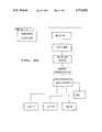
- FIG. 2is a block diagram of a system of this invention
- FIG. 3is a main panel wiring diagram of the preferred embodiment
- FIG. 4is a top plan view of a typical ATM installation employing the lighting and monitoring features of this invention
- FIG. 5is a perspective drawing of the central processing unit of this invention.
- FIG. 6is a perspective drawing of the communication/command module of this invention.
- FIG. 7is a flow diagram of the ATM light level monitoring process of this invention.
- FIGS. 8a and 8bare flow diagrams constituting extensions of FIG. 7 and show additional monitoring features of this invention.
- FIGS. 1, 2 and 3a typical installation of a commercial building employing this invention, namely a branch bank 10 and parking structure 11 with an external walkup Automatic Teller Machine, hereinafter ATM 12.
- the branch bank building 10is free standing as in FIG. 1 or may be semi attached in a shopping mall or commercial strip center.
- the branch bank 10will have a parking lot or parking structure 11 and sometimes a drive through route with either a live teller window or a second ATM installation operated by a driver/customer while in their vehicle.
- a branch bank with a multi level parking garage 11is depicted with a single walkup ATM 12 shown.
- the same principle of this inventionmay be applied to other branch bank arrangements or to other commercial facilities or businesses.
- the criteria for selection of the installationis that the business has any of the needs set forth above including customer's security lighting and the need to monitor and optimize energy consumption of the various occupancy related systems as heat/air conditioning and to detect and report abnormal conditions.
- any such installationhas an equipment center such as electrical/telephone room 14 of FIG. 1.
- Thisis the central location where, typically, telephone and data service is received and distributed within the building 10.
- Power controlsare often located in the same or nearby room.
- Heating and air conditioningis commonly supplied by a single large Heating, Ventilating, Air Conditioning (HVAC) system as shown in FIG. 1 by a number of individual units 13 located above where needed and each having individual thermostats or sensors 33 (FIG. 2) for zone control of heating and cooling.
- HVACHeating, Ventilating, Air Conditioning
- FIG. 1Heating, Ventilating, Air Conditioning
- FIG. 2Heating, Ventilating, Air Conditioning
- Eachmay have separate gas lines but electrical supply for such units will often be from the electrical/telephone room 14.
- An electrical panel 15is usually located outside of the room 14 so that occupants of the building may reset circuit breakers as needed, without gaining access to the full electrical system.
- Recent requirements such as California AB 224have specified minimum light levels for external ATM installations and require the businesses to provide a well lighted area at the ATM and in the adjacent approach paths for customer protection. Since most branch banks and commercial retail buildings are not occupied throughout each 24 hour period, a lighting failure may not be detected when it occurs and only by periodic inspections. 24 hour usage of ATM's is common so immediate detection of a lighting deficiency is essential. The presence of excess lighting will aid is maintaining minimum light levels but a total failure of lighting in the region might go undetected.
- the ATM 12 of FIG. 1is lighted by a number of lamps 20 located so as to provide area lighting and an additional set of lamps 21 at or incorporated in the ATM 12 to provide immediate area lighting.
- One or more area light level sensor assemblies 22is directed at the area A covered by the lamps 20 and includes a light level sensor 22S and a wireless transmitter 22T, each transmitter with an internal or external antenna 22AT.
- An ATM light level sensor assembly 23is directed at the ATM 12 and includes a light level sensor 23S with its associated wireless transmitter 23T and antenna 23AT.
- the number and location of lamps 20is designed to provide the minimum area light level of 2 candle power lumens at the sensor 22.
- the number and location of lamps 21is designed to provide the minimum light level at the ATM 12 of 10 candle power at sensor 23.
- a computer/communications module 30which includes a wireless receiver 31 tuned to receive data from the transmitters 22T and 23T and sensor 25 as well as other sensors and components of this system as described below.
- a wireless receiver 31tuned to receive data from the transmitters 22T and 23T and sensor 25 as well as other sensors and components of this system as described below.
- the confines of room 14are denoted by the dashed line 14.
- An optional global area sensor 24 with its transmitter 24Tis located exterior to the building 10 to observe ambient light level to establish a reference light level and act as back-up for the sensor 23.
- the sign 16 shown in FIGS. 1 and 2is powered via sign lines SL and interfacing relay 17 over a time clock controlled power line TEL from the CPU/Communicator module 30 within the room 14.
- a current sensor 32may be coupled to the sign power line TEL to monitor sign lamp current. If the current drops or stops during time clock controlled lighted periods, a sign light failure is detected and registered. Sign lighting failure is not normally related to customer safety and therefore can be reported as an abnormality which should be remedied at the next work day. Any excess current draw may indicate a short circuit and the sensor 32 will then provide a signal which is interpreted at the CPU as a dangerous condition and causes an override of the time clock to remove power to the sign 16.
- the HVAC units 13are primarily controlled by their respective thermostats such as thermostat 33 which is located inside of the building 10 of FIG. 1 to sense the temperature in the zone served by the particular unit 13.
- power to the HVAC units 13is controlled by the thermostat 33 and an interfacing relay 36 which is controlled by a time clock via line HVAC TCL.
- the line HVAC TCLterminates in the CPU/communicator unit 30 where its time clock is located.
- the timing circuit of the CPU portion of the module 30is used, thereby eliminating the need for numerous time clocks as in the usual commercial installation.
- backup poweris utilized to maintain proper timing in the system. This is in contrast with the typical commercial installation in which a power outage requires a manual resetting of all time clocks.
- the ATM 12which is typically built in to an exterior wall of a branch bank building 10 includes a console 12C, display 12D, card acceptor 12CA, keypad 12KP and a currency dispenser 12CD.
- the ATMwill include an illuminated sign 12S to indicate whether the ATM is open or not.
- Other ATM'shave mechanical covers for the display, keyboard and card accepter to prevent the use of the ATM during certain hours or under certain conditions.
- This systemis ideal for those systems employing an illuminated sign 12S which indicates whether the ATM is open or
- the sensor 23S which monitors the light level at the ATM 12 provided by lamps 21is operative, when ambient light falls below the prescribed minimum at the ATM, to communicate with CPU 30 to disable the ATM and illuminate the ATM CLOSED sign.
- the ATM 12may be closed when any one of the sensors 22 of FIG. 2 detects a light level in the general area below the accepted minimum.
- the CPU/communicator module 30is powered over the building 10 lines PL after voltage reduction to a suitable operating voltage such as 16.5 v. AC by transformer 34 and a suitable inverter(unshown) to provide DC power where required by the system.
- a backup or standby battery 35is likewise provided in the equipment room 14 which is indicated in FIG. 2 by the dashed line surrounding the equipment which is normally located within that room when using the system of this invention.
- the CPU/Communication Module 30 of FIG. 2is seen in more detail in FIGS. 5 and 6 as including a controller unit 40 (FIG. 7) of the type employed in security systems such as the Ranger 9000E Downloadable Control Communicator of Caddx-Caddi Controls, Inc. of Gladewater, Tex.
- This type of controllerprovides as many as 16 sensor inputs, 16 programmable outputs, 8 relay outputs, a basic 16 key keypad or a full English language keypad and a printer output.
- This unitmay be used as the basic controller for the system or as alternatives, a separate CPU 41 may be present or a personal computer 42 may be used, relying upon the downloadable control communicator 40 only for its multi inputs and outputs and to a degree its programmable features.
- a personal computerit should have, at least, the following:
- a full keyboard 43, a monitor 41 and a printer 44are used to complete the personal computer system.
- the communicator portion of module 30includes a data modem 50 for the communication of information over telephone lines TL to a central monitoring office.
- a central monitoring officemay be at a security company location or at a police station if the system incorporates security monitoring as well such as entrance protection or motion detection during closed hours.
- the controller 40also includes a bank of relays 51 under the control of either the CPU 41 or the control unit 42.
- the commercial controller unit identified above/belowis preferred.
- FIG. 3A simplified system is illustrated in FIG. 3 in which the same reference numerals utilized in FIGS. 1 and 2 are found in FIG. 3 to represent the same components of the system.
- the functions of this inventionmay be carried out employing certain off the shelf equipment which when configured in accordance with this teaching can provide many of the functions.
- Specially designed equipmentincludes the sensor/transmitter combination.
- Some of the standard equipment which may be used for certain functions of this inventioninclude:
- FIGS. 7, 8a and 8bconstitute a series of flow diagrams to illustrate the operation of the system.
- FIG. 7the sequence for light level monitoring at an ATM is shown.
- the CPUproceeds with its normal initialization routine which is established as part of the normal CPU setup and is dictated by the computer chosen and its operating system and subsystems used.
- the first step for operation of the particular sensing systemis the setting of the primary or light level 1 setting. This can be performed using the keyboard 43 of FIG. 5 or the controller units 42C of FIG. 6.
- the primary or light level 1is the level as sensed by the sensor 23 of FIG. 2 which senses the level of illumination directly at the face of the ATM and within 5 feet of the ATM.
- the desired or required light levelis set at the general area within 50 feet of the ATM which is designated as level 2.
- other areassuch as a parking lot near the ATM is set as light level 3 or 4.
- This stepis shown in dashed lines between setting light level 2, and setting the time cycle.
- the schedule or programming for hours of illumination for the ATM and regions covered by sensors 22S and the optional sensor 23Sare next set. This will normally include the schedule of operating hours for normal lighting. If the ATM is to be illuminated at level 1, whenever needed by reason of the ambient level falling below a standard, the schedule setting is unnecessary. The ambient light level is sensed. The light level 1 is monitored and if found to be below the stored standard, the ATM is closed and the ATM CLOSED light optionally is illuminated.
- FIGS. 8a and 8bare extensions of the flow diagram of FIG. 7 and illustrate the sequence for each of several other discrepancies such as:
- the computer programis the DL900 Ranger Upload/Download Program, Ver. 3.76 of Caddx-Caddi Controls, Inc. of Gladewater, Tex. 75647 which accompanies their RANGER Model 9000E Downloadable Control/Communicator.
Landscapes
- Engineering & Computer Science (AREA)
- Multimedia (AREA)
- Physics & Mathematics (AREA)
- General Physics & Mathematics (AREA)
- Library & Information Science (AREA)
- Circuit Arrangement For Electric Light Sources In General (AREA)
- Alarm Systems (AREA)
Abstract
Description
______________________________________ Controller Unit 4-2 Ranger 9000E Downloadable Control/Communicator of Caddx-Caddi Controls, Inc. Gladewater, Texas 75647 FA 200 Universal Transmitter FA210 Reduced Size Universal Transmitter FA400 Remote Receiver by Inovonics Corporation of Boulder, Colorado 80301 Sensors Hawkeye 5800 Mini Sensor Hawkeye 5900 Split-Core Sensor Hawkeye 5002 Remote Status Current Sensing Panel by Veris Industries, 1-800-354-8556 of 10799 S.W. Cascade Blvd., Portland, Oregon 97223 ______________________________________
Claims (15)
Priority Applications (2)
| Application Number | Priority Date | Filing Date | Title |
|---|---|---|---|
| US08/598,338US5774052A (en) | 1996-02-08 | 1996-02-08 | Monitoring and alerting system for buildings |
| US09/107,181US6121875A (en) | 1996-02-08 | 1998-06-29 | Monitoring and alerting system for buildings |
Applications Claiming Priority (1)
| Application Number | Priority Date | Filing Date | Title |
|---|---|---|---|
| US08/598,338US5774052A (en) | 1996-02-08 | 1996-02-08 | Monitoring and alerting system for buildings |
Related Child Applications (1)
| Application Number | Title | Priority Date | Filing Date |
|---|---|---|---|
| US09/107,181Continuation-In-PartUS6121875A (en) | 1996-02-08 | 1998-06-29 | Monitoring and alerting system for buildings |
Publications (1)
| Publication Number | Publication Date |
|---|---|
| US5774052Atrue US5774052A (en) | 1998-06-30 |
Family
ID=24395160
Family Applications (1)
| Application Number | Title | Priority Date | Filing Date |
|---|---|---|---|
| US08/598,338Expired - Fee RelatedUS5774052A (en) | 1996-02-08 | 1996-02-08 | Monitoring and alerting system for buildings |
Country Status (1)
| Country | Link |
|---|---|
| US (1) | US5774052A (en) |
Cited By (55)
| Publication number | Priority date | Publication date | Assignee | Title |
|---|---|---|---|---|
| US6028522A (en)* | 1998-10-14 | 2000-02-22 | Statsignal Systems, Inc. | System for monitoring the light level around an ATM |
| US6057646A (en)* | 1997-07-28 | 2000-05-02 | Pieroth; Robert F. | Light level monitoring and ATM control system for automated teller machine which directly measures light source luminance to indirectly determine area illuminance |
| US6218953B1 (en)* | 1998-10-14 | 2001-04-17 | Statsignal Systems, Inc. | System and method for monitoring the light level around an ATM |
| US6272531B1 (en)* | 1998-03-31 | 2001-08-07 | International Business Machines Corporation | Method and system for recognizing and acting upon dynamic data on the internet |
| US6305602B1 (en) | 1997-12-01 | 2001-10-23 | Diebold, Incorporated | Light monitoring system and method for automated transaction machine |
| WO2001035190A3 (en)* | 1999-11-12 | 2001-12-13 | Statsignal Systems Inc | System and method for monitoring and controlling remote devices |
| US20020013679A1 (en)* | 1998-10-14 | 2002-01-31 | Petite Thomas D. | System and method for monitoring the light level in a lighted area |
| US20020019725A1 (en)* | 1998-10-14 | 2002-02-14 | Statsignal Systems, Inc. | Wireless communication networks for providing remote monitoring of devices |
| US20020027504A1 (en)* | 1999-03-18 | 2002-03-07 | James Davis | System and method for controlling communication between a host computer and communication devices associated with remote devices in an automated monitoring system |
| WO2002011098A3 (en)* | 2000-08-01 | 2002-05-02 | Safe Passage Systems Corp | System for monitoring and testing of light sources |
| US20030200349A1 (en)* | 2002-04-17 | 2003-10-23 | Hansen James R. | XML scripting of soap commands |
| US20040084652A1 (en)* | 2002-11-01 | 2004-05-06 | Singh Ravjiv R. | Heat transfer fluid comprising difluoromethane and carbon dioxide |
| US20040177124A1 (en)* | 2000-07-28 | 2004-09-09 | Hansen James R. | Reporting the state of an apparatus to a remote computer |
| US20040263340A1 (en)* | 2003-01-31 | 2004-12-30 | Joseph Pearson | Sign sentry |
| US20050043059A1 (en)* | 2000-08-09 | 2005-02-24 | Petite Thomas D. | Systems and methods for providing remote monitoring of electricity consumption for an electric meter |
| US7079810B2 (en) | 1997-02-14 | 2006-07-18 | Statsignal Ipc, Llc | System and method for communicating with a remote communication unit via the public switched telephone network (PSTN) |
| US7117239B1 (en) | 2000-07-28 | 2006-10-03 | Axeda Corporation | Reporting the state of an apparatus to a remote computer |
| US7137550B1 (en) | 1997-02-14 | 2006-11-21 | Statsignal Ipc, Llc | Transmitter for accessing automated financial transaction machines |
| US20060267758A1 (en)* | 2005-02-18 | 2006-11-30 | Barth R T | System and method for detection of a variety of alarm conditions |
| US7149792B1 (en) | 2000-11-20 | 2006-12-12 | Axeda Corporation | Device registration mechanism |
| US7185014B1 (en) | 2000-09-22 | 2007-02-27 | Axeda Corporation | Retrieving data from a server |
| US7263073B2 (en) | 1999-03-18 | 2007-08-28 | Statsignal Ipc, Llc | Systems and methods for enabling a mobile user to notify an automated monitoring system of an emergency situation |
| US20070208535A1 (en)* | 2006-03-01 | 2007-09-06 | International Business Machines Corporation | System and method for efficient and collective adjustment of sensor reporting ranges for long-lived queries |
| US7295128B2 (en) | 1998-06-22 | 2007-11-13 | Sipco, Llc | Smoke detection methods, devices, and systems |
| US7346463B2 (en) | 2001-08-09 | 2008-03-18 | Hunt Technologies, Llc | System for controlling electrically-powered devices in an electrical network |
| US7397907B2 (en) | 1997-02-14 | 2008-07-08 | Sipco, Llc | Multi-function general purpose transceiver |
| US7424527B2 (en) | 2001-10-30 | 2008-09-09 | Sipco, Llc | System and method for transmitting pollution information over an integrated wireless network |
| US7480501B2 (en) | 2001-10-24 | 2009-01-20 | Statsignal Ipc, Llc | System and method for transmitting an emergency message over an integrated wireless network |
| US7629306B2 (en) | 2004-04-29 | 2009-12-08 | Honeywell International Inc. | Compositions comprising tetrafluoropropene and carbon dioxide |
| US7697492B2 (en) | 1998-06-22 | 2010-04-13 | Sipco, Llc | Systems and methods for monitoring and controlling remote devices |
| US7756086B2 (en) | 2004-03-03 | 2010-07-13 | Sipco, Llc | Method for communicating in dual-modes |
| EP2261296A2 (en) | 2004-04-29 | 2010-12-15 | Honeywell International Inc. | Compositions comprising tetrafluoropropene and carbon dioxide |
| US7864064B2 (en) | 1993-11-08 | 2011-01-04 | Fugitive Emissions Detection Device, Inc. | Fugitive emissions detection devices |
| US20110070904A1 (en)* | 2004-08-09 | 2011-03-24 | Mcfarland Norman R | Binding Wireless Devices In a Building Automation System |
| US7966418B2 (en) | 2003-02-21 | 2011-06-21 | Axeda Corporation | Establishing a virtual tunnel between two computer programs |
| US8000314B2 (en) | 1996-12-06 | 2011-08-16 | Ipco, Llc | Wireless network system and method for providing same |
| US8031650B2 (en) | 2004-03-03 | 2011-10-04 | Sipco, Llc | System and method for monitoring remote devices with a dual-mode wireless communication protocol |
| US8065397B2 (en) | 2006-12-26 | 2011-11-22 | Axeda Acquisition Corporation | Managing configurations of distributed devices |
| US8064412B2 (en) | 1998-06-22 | 2011-11-22 | Sipco, Llc | Systems and methods for monitoring conditions |
| US8108543B2 (en) | 2000-09-22 | 2012-01-31 | Axeda Corporation | Retrieving data from a server |
| US8370479B2 (en) | 2006-10-03 | 2013-02-05 | Axeda Acquisition Corporation | System and method for dynamically grouping devices based on present device conditions |
| US8406119B2 (en) | 2001-12-20 | 2013-03-26 | Axeda Acquisition Corporation | Adaptive device-initiated polling |
| US8410931B2 (en) | 1998-06-22 | 2013-04-02 | Sipco, Llc | Mobile inventory unit monitoring systems and methods |
| US20130103201A1 (en)* | 2008-06-02 | 2013-04-25 | Charles Huizenga | Intelligence in Distributed Lighting Control Devices |
| US8478861B2 (en) | 2007-07-06 | 2013-07-02 | Axeda Acquisition Corp. | Managing distributed devices with limited connectivity |
| US8489063B2 (en) | 2001-10-24 | 2013-07-16 | Sipco, Llc | Systems and methods for providing emergency messages to a mobile device |
| US20140196802A1 (en)* | 2011-10-13 | 2014-07-17 | Kevin Duane Guy | Fluid Leak Detection and Shutdown Apparatus |
| US8787246B2 (en) | 2009-02-03 | 2014-07-22 | Ipco, Llc | Systems and methods for facilitating wireless network communication, satellite-based wireless network systems, and aircraft-based wireless network systems, and related methods |
| US9439126B2 (en) | 2005-01-25 | 2016-09-06 | Sipco, Llc | Wireless network protocol system and methods |
| US9664814B2 (en) | 2008-06-02 | 2017-05-30 | Abl Ip Holding Llc | Wireless sensor |
| US20170316357A1 (en)* | 2016-04-28 | 2017-11-02 | Honeywell International Inc. | Systems and methods for displaying a dynamic risk level indicator of an atm site or other remote monitoring site on a map for improved remote monitoring |
| US9888548B2 (en) | 2011-12-07 | 2018-02-06 | Abl Ip Holding Llc | System for and method of commissioning lighting devices |
| US10158831B1 (en)* | 2017-06-15 | 2018-12-18 | MVI Systems, LLC | Entranceway or foyer-based, communication apparatus and system |
| CN110062917A (en)* | 2016-10-07 | 2019-07-26 | 菲利普连结科技有限责任公司 | Intelligent tow truck system |
| CN110197046A (en)* | 2019-06-12 | 2019-09-03 | 珠海格力电器股份有限公司 | Rapid model selection method of multi-split system, storage medium and processor |
Citations (5)
| Publication number | Priority date | Publication date | Assignee | Title |
|---|---|---|---|---|
| US4354181A (en)* | 1980-11-03 | 1982-10-12 | Gerber Products Company | Vapor lamp indicating device |
| US5057814A (en)* | 1989-07-24 | 1991-10-15 | Harley-Davidson, Inc. | Electrical malfunction detection system |
| US5061997A (en)* | 1990-06-21 | 1991-10-29 | Rensselaer Polytechnic Institute | Control of visible conditions in a spatial environment |
| US5091713A (en)* | 1990-05-10 | 1992-02-25 | Universal Automated Systems, Inc. | Inventory, cash, security, and maintenance control apparatus and method for a plurality of remote vending machines |
| US5471201A (en)* | 1992-06-03 | 1995-11-28 | Schlumberger Industries S.R.L. | Method and apparatus for monitoring the operating condition of lamps in a public lighting network |
- 1996
- 1996-02-08USUS08/598,338patent/US5774052A/ennot_activeExpired - Fee Related
Patent Citations (5)
| Publication number | Priority date | Publication date | Assignee | Title |
|---|---|---|---|---|
| US4354181A (en)* | 1980-11-03 | 1982-10-12 | Gerber Products Company | Vapor lamp indicating device |
| US5057814A (en)* | 1989-07-24 | 1991-10-15 | Harley-Davidson, Inc. | Electrical malfunction detection system |
| US5091713A (en)* | 1990-05-10 | 1992-02-25 | Universal Automated Systems, Inc. | Inventory, cash, security, and maintenance control apparatus and method for a plurality of remote vending machines |
| US5061997A (en)* | 1990-06-21 | 1991-10-29 | Rensselaer Polytechnic Institute | Control of visible conditions in a spatial environment |
| US5471201A (en)* | 1992-06-03 | 1995-11-28 | Schlumberger Industries S.R.L. | Method and apparatus for monitoring the operating condition of lamps in a public lighting network |
Cited By (123)
| Publication number | Priority date | Publication date | Assignee | Title |
|---|---|---|---|---|
| US7864064B2 (en) | 1993-11-08 | 2011-01-04 | Fugitive Emissions Detection Device, Inc. | Fugitive emissions detection devices |
| US8000314B2 (en) | 1996-12-06 | 2011-08-16 | Ipco, Llc | Wireless network system and method for providing same |
| US8625496B2 (en) | 1996-12-06 | 2014-01-07 | Ipco, Llc | Wireless network system and method for providing same |
| US8233471B2 (en) | 1996-12-06 | 2012-07-31 | Ipco, Llc | Wireless network system and method for providing same |
| US8982856B2 (en) | 1996-12-06 | 2015-03-17 | Ipco, Llc | Systems and methods for facilitating wireless network communication, satellite-based wireless network systems, and aircraft-based wireless network systems, and related methods |
| US7397907B2 (en) | 1997-02-14 | 2008-07-08 | Sipco, Llc | Multi-function general purpose transceiver |
| US7137550B1 (en) | 1997-02-14 | 2006-11-21 | Statsignal Ipc, Llc | Transmitter for accessing automated financial transaction machines |
| US7079810B2 (en) | 1997-02-14 | 2006-07-18 | Statsignal Ipc, Llc | System and method for communicating with a remote communication unit via the public switched telephone network (PSTN) |
| US6057646A (en)* | 1997-07-28 | 2000-05-02 | Pieroth; Robert F. | Light level monitoring and ATM control system for automated teller machine which directly measures light source luminance to indirectly determine area illuminance |
| US6305602B1 (en) | 1997-12-01 | 2001-10-23 | Diebold, Incorporated | Light monitoring system and method for automated transaction machine |
| US6272531B1 (en)* | 1998-03-31 | 2001-08-07 | International Business Machines Corporation | Method and system for recognizing and acting upon dynamic data on the internet |
| US6437692B1 (en)* | 1998-06-22 | 2002-08-20 | Statsignal Systems, Inc. | System and method for monitoring and controlling remote devices |
| US9129497B2 (en) | 1998-06-22 | 2015-09-08 | Statsignal Systems, Inc. | Systems and methods for monitoring conditions |
| US8410931B2 (en) | 1998-06-22 | 2013-04-02 | Sipco, Llc | Mobile inventory unit monitoring systems and methods |
| US9691263B2 (en) | 1998-06-22 | 2017-06-27 | Sipco, Llc | Systems and methods for monitoring conditions |
| US7295128B2 (en) | 1998-06-22 | 2007-11-13 | Sipco, Llc | Smoke detection methods, devices, and systems |
| US9571582B2 (en) | 1998-06-22 | 2017-02-14 | Sipco, Llc | Systems and methods for monitoring and controlling remote devices |
| US20020125998A1 (en)* | 1998-06-22 | 2002-09-12 | Petite Thomas D. | System and method for monitoring and controlling remote devices |
| US9430936B2 (en) | 1998-06-22 | 2016-08-30 | Sipco Llc | Systems and methods for monitoring and controlling remote devices |
| US7053767B2 (en) | 1998-06-22 | 2006-05-30 | Statsignal Systems, Inc. | System and method for monitoring and controlling remote devices |
| US7697492B2 (en) | 1998-06-22 | 2010-04-13 | Sipco, Llc | Systems and methods for monitoring and controlling remote devices |
| US8964708B2 (en) | 1998-06-22 | 2015-02-24 | Sipco Llc | Systems and methods for monitoring and controlling remote devices |
| US8223010B2 (en) | 1998-06-22 | 2012-07-17 | Sipco Llc | Systems and methods for monitoring vehicle parking |
| US8064412B2 (en) | 1998-06-22 | 2011-11-22 | Sipco, Llc | Systems and methods for monitoring conditions |
| US8013732B2 (en) | 1998-06-22 | 2011-09-06 | Sipco, Llc | Systems and methods for monitoring and controlling remote devices |
| US8212667B2 (en) | 1998-06-22 | 2012-07-03 | Sipco, Llc | Automotive diagnostic data monitoring systems and methods |
| US7103511B2 (en) | 1998-10-14 | 2006-09-05 | Statsignal Ipc, Llc | Wireless communication networks for providing remote monitoring of devices |
| US6218953B1 (en)* | 1998-10-14 | 2001-04-17 | Statsignal Systems, Inc. | System and method for monitoring the light level around an ATM |
| US20020013679A1 (en)* | 1998-10-14 | 2002-01-31 | Petite Thomas D. | System and method for monitoring the light level in a lighted area |
| US20020019725A1 (en)* | 1998-10-14 | 2002-02-14 | Statsignal Systems, Inc. | Wireless communication networks for providing remote monitoring of devices |
| US6028522A (en)* | 1998-10-14 | 2000-02-22 | Statsignal Systems, Inc. | System for monitoring the light level around an ATM |
| US8924588B2 (en) | 1999-03-18 | 2014-12-30 | Sipco, Llc | Systems and methods for controlling communication between a host computer and communication devices |
| US8930571B2 (en) | 1999-03-18 | 2015-01-06 | Sipco, LLP | Systems and methods for controlling communication between a host computer and communication devices |
| US7263073B2 (en) | 1999-03-18 | 2007-08-28 | Statsignal Ipc, Llc | Systems and methods for enabling a mobile user to notify an automated monitoring system of an emergency situation |
| US8924587B2 (en) | 1999-03-18 | 2014-12-30 | Sipco, Llc | Systems and methods for controlling communication between a host computer and communication devices |
| US20020027504A1 (en)* | 1999-03-18 | 2002-03-07 | James Davis | System and method for controlling communication between a host computer and communication devices associated with remote devices in an automated monitoring system |
| US7650425B2 (en) | 1999-03-18 | 2010-01-19 | Sipco, Llc | System and method for controlling communication between a host computer and communication devices associated with remote devices in an automated monitoring system |
| WO2001035190A3 (en)* | 1999-11-12 | 2001-12-13 | Statsignal Systems Inc | System and method for monitoring and controlling remote devices |
| US20040177124A1 (en)* | 2000-07-28 | 2004-09-09 | Hansen James R. | Reporting the state of an apparatus to a remote computer |
| US7117239B1 (en) | 2000-07-28 | 2006-10-03 | Axeda Corporation | Reporting the state of an apparatus to a remote computer |
| US8898294B2 (en) | 2000-07-28 | 2014-11-25 | Axeda Corporation | Reporting the state of an apparatus to a remote computer |
| US8055758B2 (en) | 2000-07-28 | 2011-11-08 | Axeda Corporation | Reporting the state of an apparatus to a remote computer |
| US6717660B1 (en)* | 2000-08-01 | 2004-04-06 | Safe Passage Systems Corporation | System for monitoring and testing of light sources |
| WO2002011098A3 (en)* | 2000-08-01 | 2002-05-02 | Safe Passage Systems Corp | System for monitoring and testing of light sources |
| US7209840B2 (en) | 2000-08-09 | 2007-04-24 | Hunt Technologies, Llc | Systems and methods for providing remote monitoring of electricity consumption for an electric meter |
| US20050043059A1 (en)* | 2000-08-09 | 2005-02-24 | Petite Thomas D. | Systems and methods for providing remote monitoring of electricity consumption for an electric meter |
| US8762497B2 (en) | 2000-09-22 | 2014-06-24 | Axeda Corporation | Retrieving data from a server |
| US7185014B1 (en) | 2000-09-22 | 2007-02-27 | Axeda Corporation | Retrieving data from a server |
| US7937370B2 (en) | 2000-09-22 | 2011-05-03 | Axeda Corporation | Retrieving data from a server |
| US8108543B2 (en) | 2000-09-22 | 2012-01-31 | Axeda Corporation | Retrieving data from a server |
| US10069937B2 (en) | 2000-09-22 | 2018-09-04 | Ptc Inc. | Retrieving data from a server |
| US7149792B1 (en) | 2000-11-20 | 2006-12-12 | Axeda Corporation | Device registration mechanism |
| US7346463B2 (en) | 2001-08-09 | 2008-03-18 | Hunt Technologies, Llc | System for controlling electrically-powered devices in an electrical network |
| US9282029B2 (en) | 2001-10-24 | 2016-03-08 | Sipco, Llc. | System and method for transmitting an emergency message over an integrated wireless network |
| US8489063B2 (en) | 2001-10-24 | 2013-07-16 | Sipco, Llc | Systems and methods for providing emergency messages to a mobile device |
| US7480501B2 (en) | 2001-10-24 | 2009-01-20 | Statsignal Ipc, Llc | System and method for transmitting an emergency message over an integrated wireless network |
| US10687194B2 (en) | 2001-10-24 | 2020-06-16 | Sipco, Llc | Systems and methods for providing emergency messages to a mobile device |
| US10149129B2 (en) | 2001-10-24 | 2018-12-04 | Sipco, Llc | Systems and methods for providing emergency messages to a mobile device |
| US9615226B2 (en) | 2001-10-24 | 2017-04-04 | Sipco, Llc | System and method for transmitting an emergency message over an integrated wireless network |
| US8666357B2 (en) | 2001-10-24 | 2014-03-04 | Sipco, Llc | System and method for transmitting an emergency message over an integrated wireless network |
| US9111240B2 (en) | 2001-10-30 | 2015-08-18 | Sipco, Llc. | System and method for transmitting pollution information over an integrated wireless network |
| US7424527B2 (en) | 2001-10-30 | 2008-09-09 | Sipco, Llc | System and method for transmitting pollution information over an integrated wireless network |
| US8171136B2 (en) | 2001-10-30 | 2012-05-01 | Sipco, Llc | System and method for transmitting pollution information over an integrated wireless network |
| US9515691B2 (en) | 2001-10-30 | 2016-12-06 | Sipco, Llc. | System and method for transmitting pollution information over an integrated wireless network |
| US9674067B2 (en) | 2001-12-20 | 2017-06-06 | PTC, Inc. | Adaptive device-initiated polling |
| US9170902B2 (en) | 2001-12-20 | 2015-10-27 | Ptc Inc. | Adaptive device-initiated polling |
| US8406119B2 (en) | 2001-12-20 | 2013-03-26 | Axeda Acquisition Corporation | Adaptive device-initiated polling |
| US8752074B2 (en) | 2002-04-17 | 2014-06-10 | Axeda Corporation | Scripting of soap commands |
| US10708346B2 (en) | 2002-04-17 | 2020-07-07 | Ptc Inc. | Scripting of soap commands |
| US7178149B2 (en) | 2002-04-17 | 2007-02-13 | Axeda Corporation | XML scripting of soap commands |
| US20030200349A1 (en)* | 2002-04-17 | 2003-10-23 | Hansen James R. | XML scripting of soap commands |
| US8060886B2 (en) | 2002-04-17 | 2011-11-15 | Axeda Corporation | XML scripting of SOAP commands |
| US9591065B2 (en) | 2002-04-17 | 2017-03-07 | Ptc Inc. | Scripting of SOAP commands |
| US20040084652A1 (en)* | 2002-11-01 | 2004-05-06 | Singh Ravjiv R. | Heat transfer fluid comprising difluoromethane and carbon dioxide |
| US7238299B2 (en) | 2002-11-01 | 2007-07-03 | Honeywell International Inc. | Heat transfer fluid comprising difluoromethane and carbon dioxide |
| EP2253686A2 (en) | 2002-11-01 | 2010-11-24 | Honeywell International Inc. | Heat transfer fluid comprising difluoromethane and carbon dioxide |
| US6965307B2 (en) | 2003-01-31 | 2005-11-15 | Pearson Jr Joseph | Sign sentry |
| US20040263340A1 (en)* | 2003-01-31 | 2004-12-30 | Joseph Pearson | Sign sentry |
| US9002980B2 (en) | 2003-02-21 | 2015-04-07 | Axeda Corporation | Establishing a virtual tunnel between two computer programs |
| US10069939B2 (en) | 2003-02-21 | 2018-09-04 | Ptc Inc. | Establishing a virtual tunnel between two computers |
| US7966418B2 (en) | 2003-02-21 | 2011-06-21 | Axeda Corporation | Establishing a virtual tunnel between two computer programs |
| US8291039B2 (en) | 2003-02-21 | 2012-10-16 | Axeda Corporation | Establishing a virtual tunnel between two computer programs |
| US8031650B2 (en) | 2004-03-03 | 2011-10-04 | Sipco, Llc | System and method for monitoring remote devices with a dual-mode wireless communication protocol |
| US8379564B2 (en) | 2004-03-03 | 2013-02-19 | Sipco, Llc | System and method for monitoring remote devices with a dual-mode wireless communication protocol |
| US8446884B2 (en) | 2004-03-03 | 2013-05-21 | Sipco, Llc | Dual-mode communication devices, methods and systems |
| US7756086B2 (en) | 2004-03-03 | 2010-07-13 | Sipco, Llc | Method for communicating in dual-modes |
| US7629306B2 (en) | 2004-04-29 | 2009-12-08 | Honeywell International Inc. | Compositions comprising tetrafluoropropene and carbon dioxide |
| US9884946B2 (en) | 2004-04-29 | 2018-02-06 | Honeywell International Inc. | Compositions containing tetrafluoropropene and carbon dioxide |
| EP2261296A2 (en) | 2004-04-29 | 2010-12-15 | Honeywell International Inc. | Compositions comprising tetrafluoropropene and carbon dioxide |
| US8200273B2 (en)* | 2004-08-09 | 2012-06-12 | Siemens Industry, Inc. | Binding wireless devices in a building automation system |
| US20110070904A1 (en)* | 2004-08-09 | 2011-03-24 | Mcfarland Norman R | Binding Wireless Devices In a Building Automation System |
| US10356687B2 (en) | 2005-01-25 | 2019-07-16 | Sipco, Llc | Wireless network protocol systems and methods |
| US9860820B2 (en) | 2005-01-25 | 2018-01-02 | Sipco, Llc | Wireless network protocol systems and methods |
| US9439126B2 (en) | 2005-01-25 | 2016-09-06 | Sipco, Llc | Wireless network protocol system and methods |
| US11039371B2 (en) | 2005-01-25 | 2021-06-15 | Sipco, Llc | Wireless network protocol systems and methods |
| US20060267758A1 (en)* | 2005-02-18 | 2006-11-30 | Barth R T | System and method for detection of a variety of alarm conditions |
| US20080052041A1 (en)* | 2006-03-01 | 2008-02-28 | International Business Machines Corporation | System and method for efficient and collective adjustment of sensor reporting ranges for long-lived queries |
| US7496477B2 (en) | 2006-03-01 | 2009-02-24 | International Business Machines Corporation | System and method for efficient and collective adjustment of sensor reporting ranges for long-lived queries |
| US7302362B2 (en)* | 2006-03-01 | 2007-11-27 | International Business Machines Corporation | System and method for efficient and collective adjustment of sensor reporting ranges for long-lived queries |
| US20070208535A1 (en)* | 2006-03-01 | 2007-09-06 | International Business Machines Corporation | System and method for efficient and collective adjustment of sensor reporting ranges for long-lived queries |
| US8769095B2 (en) | 2006-10-03 | 2014-07-01 | Axeda Acquisition Corp. | System and method for dynamically grouping devices based on present device conditions |
| US10212055B2 (en) | 2006-10-03 | 2019-02-19 | Ptc Inc. | System and method for dynamically grouping devices based on present device conditions |
| US8370479B2 (en) | 2006-10-03 | 2013-02-05 | Axeda Acquisition Corporation | System and method for dynamically grouping devices based on present device conditions |
| US9491071B2 (en) | 2006-10-03 | 2016-11-08 | Ptc Inc. | System and method for dynamically grouping devices based on present device conditions |
| US9491049B2 (en) | 2006-12-26 | 2016-11-08 | Ptc Inc. | Managing configurations of distributed devices |
| US8065397B2 (en) | 2006-12-26 | 2011-11-22 | Axeda Acquisition Corporation | Managing configurations of distributed devices |
| US9712385B2 (en) | 2006-12-26 | 2017-07-18 | PTC, Inc. | Managing configurations of distributed devices |
| US8788632B2 (en) | 2006-12-26 | 2014-07-22 | Axeda Acquisition Corp. | Managing configurations of distributed devices |
| US8478861B2 (en) | 2007-07-06 | 2013-07-02 | Axeda Acquisition Corp. | Managing distributed devices with limited connectivity |
| US9664814B2 (en) | 2008-06-02 | 2017-05-30 | Abl Ip Holding Llc | Wireless sensor |
| US20130103201A1 (en)* | 2008-06-02 | 2013-04-25 | Charles Huizenga | Intelligence in Distributed Lighting Control Devices |
| US10139787B2 (en)* | 2008-06-02 | 2018-11-27 | Abl Ip Holding Llc | Intelligence in distributed lighting control devices |
| US8787246B2 (en) | 2009-02-03 | 2014-07-22 | Ipco, Llc | Systems and methods for facilitating wireless network communication, satellite-based wireless network systems, and aircraft-based wireless network systems, and related methods |
| US20140196802A1 (en)* | 2011-10-13 | 2014-07-17 | Kevin Duane Guy | Fluid Leak Detection and Shutdown Apparatus |
| US9888548B2 (en) | 2011-12-07 | 2018-02-06 | Abl Ip Holding Llc | System for and method of commissioning lighting devices |
| US10111308B2 (en) | 2011-12-07 | 2018-10-23 | Abl Ip Holding Llc | System for and method of commissioning lighting devices within a wireless network |
| US20170316357A1 (en)* | 2016-04-28 | 2017-11-02 | Honeywell International Inc. | Systems and methods for displaying a dynamic risk level indicator of an atm site or other remote monitoring site on a map for improved remote monitoring |
| CN110062917A (en)* | 2016-10-07 | 2019-07-26 | 菲利普连结科技有限责任公司 | Intelligent tow truck system |
| US11479312B2 (en) | 2016-10-07 | 2022-10-25 | Phillips Connect Technologies, LLC | Smart trailer system |
| US11912359B2 (en) | 2016-10-07 | 2024-02-27 | Phillips Connect Technologies Llc | Smart trailer system |
| US10560664B2 (en) | 2017-06-15 | 2020-02-11 | Mvi Industries, Llc | Entranceway or foyer-based, communication apparatus and system |
| US10158831B1 (en)* | 2017-06-15 | 2018-12-18 | MVI Systems, LLC | Entranceway or foyer-based, communication apparatus and system |
| CN110197046A (en)* | 2019-06-12 | 2019-09-03 | 珠海格力电器股份有限公司 | Rapid model selection method of multi-split system, storage medium and processor |
Similar Documents
| Publication | Publication Date | Title |
|---|---|---|
| US5774052A (en) | Monitoring and alerting system for buildings | |
| US6121875A (en) | Monitoring and alerting system for buildings | |
| US6894617B2 (en) | Human guard enhancing multiple site integrated security system | |
| US5689235A (en) | Electronic security system | |
| US8456305B2 (en) | Redundant security system | |
| US6392538B1 (en) | Advanced services interactive security system | |
| US8638218B2 (en) | Wireless takeover of an alarm system | |
| US6453687B2 (en) | Refrigeration monitor unit | |
| US8350698B2 (en) | Method and protocol for real time security system | |
| US7081815B2 (en) | Radio frequency security system, method for a building facility or the like, and apparatus and methods for remotely monitoring the status of fire extinguishers | |
| US5959549A (en) | Communal metering system | |
| US6308272B1 (en) | Security system using existing network and personal computers | |
| KR100543891B1 (en) | Electrical safety circuit breaker with ubiquitous function and control method | |
| EP2144209A1 (en) | System for monitoring security systems | |
| US7599816B2 (en) | Maintenance-information providing system | |
| KR100821682B1 (en) | Network Management System of Emergency Door Automatic Switch and Management Method Using the Same | |
| GB2280709A (en) | Building security system | |
| US5485628A (en) | Renewal management system | |
| KR900000825B1 (en) | General guest room control system | |
| RU33251U1 (en) | A system for collecting and processing information from security alarm systems and access control to an object | |
| US3964044A (en) | Multiple operating alarm systems employing oil burner flame monitoring relays | |
| GB2264802A (en) | Signal communication systems | |
| KR200259792Y1 (en) | Multi-use fire detection and security system | |
| US20250225861A1 (en) | Premises intersystem operations | |
| US20240338012A1 (en) | Premises environment platform with multi-system battery backup functionality |
Legal Events
| Date | Code | Title | Description |
|---|---|---|---|
| AS | Assignment | Owner name:PACIFIC BANK TECHNOLOGY, INC., CALIFORNIA Free format text:ASSIGNMENT OF ASSIGNORS INTEREST;ASSIGNORS:HAMM, DENNIS;KIMMICH, DAVID P.;REEL/FRAME:007884/0986 Effective date:19960207 | |
| FEPP | Fee payment procedure | Free format text:PAYOR NUMBER ASSIGNED (ORIGINAL EVENT CODE: ASPN); ENTITY STATUS OF PATENT OWNER: SMALL ENTITY | |
| FPAY | Fee payment | Year of fee payment:4 | |
| REMI | Maintenance fee reminder mailed | ||
| AS | Assignment | Owner name:HAMILTON PACIFIC HOLDING, LLC, CALIFORNIA Free format text:ASSIGNMENT OF ASSIGNORS INTEREST;ASSIGNOR:PACIFIC BANK TECHNOLOGY, INC.;REEL/FRAME:016226/0481 Effective date:20050629 | |
| AS | Assignment | Owner name:HAMILTON PACIFIC, L.P., CALIFORNIA Free format text:ASSIGNMENT OF ASSIGNORS INTEREST;ASSIGNOR:HAMILTON PACIFIC HOLDING, LLC;REEL/FRAME:016274/0944 Effective date:20050718 | |
| FPAY | Fee payment | Year of fee payment:8 | |
| AS | Assignment | Owner name:SECURITAS SECURITY SYSTEMS USA, INC., CALIFORNIA Free format text:ASSIGNMENT OF ASSIGNORS INTEREST;ASSIGNOR:HAMILTON PACIFIC, L.P.;REEL/FRAME:017186/0639 Effective date:20051006 | |
| AS | Assignment | Owner name:NISCAYAH, INC., GEORGIA Free format text:CHANGE OF NAME;ASSIGNOR:HAMILTON PACIFIC;REEL/FRAME:021387/0509 Effective date:20080625 | |
| AS | Assignment | Owner name:NISCAYAH, INC., GEORGIA Free format text:CORRECTIVE ASSIGNMENT TO CORRECT THE PATENT NUMBER 5774045, PREVIOUSLY RECORDED ON REEL 021387 FRAME 0509. ASSIGNOR(S) HEREBY CONFIRMS THE CHANGE OF NAME.;ASSIGNOR:HAMILTON PACIFIC;REEL/FRAME:021423/0846 Effective date:20080625 | |
| REMI | Maintenance fee reminder mailed | ||
| LAPS | Lapse for failure to pay maintenance fees | ||
| LAPS | Lapse for failure to pay maintenance fees | Free format text:PATENT EXPIRED FOR FAILURE TO PAY MAINTENANCE FEES (ORIGINAL EVENT CODE: EXP.); ENTITY STATUS OF PATENT OWNER: SMALL ENTITY | |
| STCH | Information on status: patent discontinuation | Free format text:PATENT EXPIRED DUE TO NONPAYMENT OF MAINTENANCE FEES UNDER 37 CFR 1.362 | |
| FP | Lapsed due to failure to pay maintenance fee | Effective date:20100630 |