US5774041A - Designer chime cover - Google Patents
Designer chime coverDownload PDFInfo
- Publication number
- US5774041A US5774041AUS08/684,291US68429196AUS5774041AUS 5774041 AUS5774041 AUS 5774041AUS 68429196 AUS68429196 AUS 68429196AUS 5774041 AUS5774041 AUS 5774041A
- Authority
- US
- United States
- Prior art keywords
- assembly
- set forth
- front wall
- plate
- base
- Prior art date
- Legal status (The legal status is an assumption and is not a legal conclusion. Google has not performed a legal analysis and makes no representation as to the accuracy of the status listed.)
- Expired - Fee Related
Links
Images

Classifications
- G—PHYSICS
- G10—MUSICAL INSTRUMENTS; ACOUSTICS
- G10K—SOUND-PRODUCING DEVICES; METHODS OR DEVICES FOR PROTECTING AGAINST, OR FOR DAMPING, NOISE OR OTHER ACOUSTIC WAVES IN GENERAL; ACOUSTICS NOT OTHERWISE PROVIDED FOR
- G10K9/00—Devices in which sound is produced by vibrating a diaphragm or analogous element, e.g. fog horns, vehicle hooters or buzzers
- G10K9/18—Details, e.g. bulbs, pumps, pistons, switches or casings
Definitions
- the subject inventionrelates to a door chime housing of the type mounted on a wall in a residence for providing an audible sound in response to activation of a doorbell next to a door on the exterior of the residence.
- a chime cover assemblycomprising a box-like housing for supporting the electrical components of a door chime and including a cover presenting a front wall and a base for mounting to a wall.
- the assemblyis characterized by a decorative plate for being covered with wallpaper, or the like, and thereafter secured to the cover.
- the purchaser of the door chime housingmay decorate the housing with wallpaper, fabric, or the like, which matches the decor of the residence.
- FIG. 1is a perspective view of the subject invention mounted on a wall
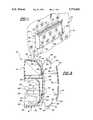
- FIG. 2is an exploded perspective view of the subject invention.
- FIG. 3is an exploded cross-sectional view taken substantially along line 3--3 of FIG. 2 but showing an alternative trim strip.
- the chime cover assembly 10comprises a box-like housing for supporting the electrical components (not shown) of a door chime.
- the housingincludes a cover, generally indicated at 12, and a base, generally indicated at 14, for mounting to a wall 16.
- the cover 12comprises an integral plastic member and the base 14 comprises an integral plastic member.
- the cover 12presents a front wall 18, end walls 20 a top wall 22 and a bottom wall 24.
- the base 14includes a peripheral wall 26 to engage and support the walls 20, 22 and 24 of the cover 12 so that the base 14 and the front wall 18 are interconnected by the end walls 20 and top 22 and bottom 24 walls.
- the peripheral wall 26 of the base 14 and the walls 20, 22 and 24 of the cover 12present offset and overlapping flanges 28 for mating engagement of the cover 12 on the base 14.
- the assembly 10is characterized by a decorative plate 30 for being covered with wallpaper, fabric, and the like, 32 and is secured to the front wall 18 of the cover 12.
- the front wall 18has holes 34 therein and the plate 30 includes integral projections 36 extending therefrom for insertion into the holes 34 for securing the plate 30 to the front wall 18.
- clamping claws 38are disposed on the interior of the front wall 18 and surrounding the holes 34 for gripping the projections 36 at various degrees of insertion thereinto to accommodate various different thicknesses of the decorative wallpaper or fabric 32 in other words, the clamping claws 38 allow an adjustment of the distance the plate 30 is positioned from the front wall 18.
- the platehas top and bottom edges 40 and end edges 42 and the top and bottom edges 40 of the plate 30 are spaced inwardly from the top 22 and bottom 24 walls respectively of the cover 12 to define trim areas 44 between the top edge 40 of the plate 18 and the top wall 22 of the cover 12 and between the bottom edge 40 of the plate 30 and the bottom wall 24 of the cover 12.
- the wallpaper or fabric 32is wrapped around the top and bottom edges 40 of plate 30 and may be clamped to the front wall 18 and/or may be adhesively secured to the plate 30.
- trim stripsare included for attachment to the housing in the trim areas 44, which trim areas 44 cut the corners between the front wall 18 and the top 22 and bottom 24 walls respectively to present slanted surfaces.
- the trim strips 46are wood and may be secured to the trim areas 44 by adhesive or VelcroTM.
- the trim strips 48are plastic and present flat surfaces 50 for receiving decorative sheets of material, such as decorative tape.
- the trim strips 48present an upturned edge or abutment 52 for abutting the adjacent one of the top and bottom edges 40 of the plate 30.
- the upturned edge 52has a top surface with a groove therein for receiving and retaining a decorative bead 54 therein, as for example, a gold or silver bead.
- the trim areas 44have apertures 56 therein and the plastic trim strips 48 have integral posts 58 extending therefrom for insertion into the apertures 56 for securing the trim strips 48 to the trim areas 44.
- the posts 58 and/or the apertures 56may include coacting clamping claws or barbs for retaining the posts 58 in the apertures 56.
- the posts 58extend at an acute angle relative to the flat surfaces 50 of the plastic trim strips 48 so as to extend substantially perpendicular to the base 14 when attached to the trim areas 44.
- the end walls 20 of the housingextend into flanges 60 above the front wall 18 to abut the end edges 40 of the plate 30 and the ends of the trim strips 46 and 48.
- the flanges 60 of the end walls 40extend a greater distance above the trim areas 44 than above the above the front wall 18 because of the slanted or falling away disposition of the trim areas 44.
- the base 14includes a battery box 62 extending from the base 14 toward the front wall 18 and is open through the base for placing a battery (not shown) therein from the rear of the assembly.
- the battery box 62is adjacent the bottom wall 24 and one end 20 of the housing and is open to the bottom wall 24.
- the battery box 62includes two pair of retainer flanges 64 at the inner end of the interior of the battery box 62 for receiving an electrical connector (not shown). Although not shown, the other end of the battery box includes another pair of such retainer flanges.
- the battery boxhas a lead opening 66 in the inner end thereof for the passage of electrical leads therethrough between the battery and a circuit board (not shown).
- the base 14includes a C-shaped depression 68 opening into the battery box 62 at the inner end of the battery box 62 and extending the lead opening 66 through the base 14.
- the base 14includes a speaker support baffle 70 for receiving an audio speaker assembly (not shown).
- the speaker support baffle 70opens toward the top wall 22 and the top wall 22 has slots 72 therein adjacent the speaker support baffle 70 for allowing the audio sound waves to pass therethrough.
- the speaker support baffle 70is disposed adjacent one end 40 of the cover 12 to define an L-shaped space in the remainder of the base 14 surrounding the battery box 62 and the speaker support baffle 70.
- a plurality of support pilings 74extend upwardly from the base 14 in the L-shaped space for supporting a circuit board.
- the base 14presents lead retainer ribs 82 which are integral with the base 14 for frictionally retaining electrical leads.
- the base 14also includes mounting means for mounting the assembly on the wall 16 in the form of the well known nail or screw head receiving slots 84.
Landscapes
- Physics & Mathematics (AREA)
- Engineering & Computer Science (AREA)
- Acoustics & Sound (AREA)
- Multimedia (AREA)
- Casings For Electric Apparatus (AREA)
Abstract
Description
The subject invention relates to a door chime housing of the type mounted on a wall in a residence for providing an audible sound in response to activation of a doorbell next to a door on the exterior of the residence.
Numerous door chime housings are known in the prior art with various different designs. However, these prior art assemblies each provide a fixed decor to the purchaser. Examples of such assemblies are shown in U.S. Pat. Nos. Des. 133,228 to Dourson, Des. 264,320 to Doggart, Des. 306,565, to Pawlik et al, Des. 312,570 to Lomas and Des. 355,143 to Lee et al.
A chime cover assembly comprising a box-like housing for supporting the electrical components of a door chime and including a cover presenting a front wall and a base for mounting to a wall. The assembly is characterized by a decorative plate for being covered with wallpaper, or the like, and thereafter secured to the cover.
Therefore, in accordance with the subject invention the purchaser of the door chime housing may decorate the housing with wallpaper, fabric, or the like, which matches the decor of the residence.
Other advantages of the present invention will be readily appreciated as the same becomes better understood by reference to the following detailed description when considered in connection with the accompanying drawings wherein:
FIG. 1 is a perspective view of the subject invention mounted on a wall;
FIG. 2 is an exploded perspective view of the subject invention; and
FIG. 3 is an exploded cross-sectional view taken substantially alongline 3--3 of FIG. 2 but showing an alternative trim strip.
Referring to the Figures, wherein like numerals reference like or corresponding parts throughout the several views, a chime cover assembly constructed in accordance with the subject invention is generally shown at 10. Thechime cover assembly 10 comprises a box-like housing for supporting the electrical components (not shown) of a door chime. The housing includes a cover, generally indicated at 12, and a base, generally indicated at 14, for mounting to awall 16. Thecover 12 comprises an integral plastic member and thebase 14 comprises an integral plastic member. Thecover 12 presents afront wall 18, end walls 20 atop wall 22 and abottom wall 24. Thebase 14 includes aperipheral wall 26 to engage and support thewalls cover 12 so that thebase 14 and thefront wall 18 are interconnected by theend walls 20 and top 22 andbottom 24 walls. Theperipheral wall 26 of thebase 14 and thewalls cover 12 present offset and overlappingflanges 28 for mating engagement of thecover 12 on thebase 14.
Theassembly 10 is characterized by adecorative plate 30 for being covered with wallpaper, fabric, and the like, 32 and is secured to thefront wall 18 of thecover 12. Thefront wall 18 hasholes 34 therein and theplate 30 includesintegral projections 36 extending therefrom for insertion into theholes 34 for securing theplate 30 to thefront wall 18. More specifically, clampingclaws 38 are disposed on the interior of thefront wall 18 and surrounding theholes 34 for gripping theprojections 36 at various degrees of insertion thereinto to accommodate various different thicknesses of the decorative wallpaper orfabric 32 in other words, theclamping claws 38 allow an adjustment of the distance theplate 30 is positioned from thefront wall 18.
The plate has top andbottom edges 40 andend edges 42 and the top andbottom edges 40 of theplate 30 are spaced inwardly from thetop 22 andbottom 24 walls respectively of thecover 12 to definetrim areas 44 between thetop edge 40 of theplate 18 and thetop wall 22 of thecover 12 and between thebottom edge 40 of theplate 30 and thebottom wall 24 of thecover 12. The wallpaper orfabric 32 is wrapped around the top andbottom edges 40 ofplate 30 and may be clamped to thefront wall 18 and/or may be adhesively secured to theplate 30.
A variety of trim strips are included for attachment to the housing in thetrim areas 44, whichtrim areas 44 cut the corners between thefront wall 18 and the top 22 andbottom 24 walls respectively to present slanted surfaces. In one instance thetrim strips 46 are wood and may be secured to thetrim areas 44 by adhesive or Velcro™. Alternatively, thetrim strips 48 are plastic and presentflat surfaces 50 for receiving decorative sheets of material, such as decorative tape. Thetrim strips 48 present an upturned edge orabutment 52 for abutting the adjacent one of the top andbottom edges 40 of theplate 30. Theupturned edge 52 has a top surface with a groove therein for receiving and retaining adecorative bead 54 therein, as for example, a gold or silver bead.
Thetrim areas 44 haveapertures 56 therein and theplastic trim strips 48 haveintegral posts 58 extending therefrom for insertion into theapertures 56 for securing thetrim strips 48 to thetrim areas 44. Theposts 58 and/or theapertures 56 may include coacting clamping claws or barbs for retaining theposts 58 in theapertures 56. Theposts 58 extend at an acute angle relative to theflat surfaces 50 of theplastic trim strips 48 so as to extend substantially perpendicular to thebase 14 when attached to thetrim areas 44.
Theend walls 20 of the housing extend intoflanges 60 above thefront wall 18 to abut theend edges 40 of theplate 30 and the ends of thetrim strips flanges 60 of theend walls 40 extend a greater distance above thetrim areas 44 than above the above thefront wall 18 because of the slanted or falling away disposition of thetrim areas 44.
Thebase 14 includes abattery box 62 extending from thebase 14 toward thefront wall 18 and is open through the base for placing a battery (not shown) therein from the rear of the assembly. Thebattery box 62 is adjacent thebottom wall 24 and oneend 20 of the housing and is open to thebottom wall 24. Thebattery box 62 includes two pair ofretainer flanges 64 at the inner end of the interior of thebattery box 62 for receiving an electrical connector (not shown). Although not shown, the other end of the battery box includes another pair of such retainer flanges. The battery box has alead opening 66 in the inner end thereof for the passage of electrical leads therethrough between the battery and a circuit board (not shown). Thebase 14 includes a C-shaped depression 68 opening into thebattery box 62 at the inner end of thebattery box 62 and extending the lead opening 66 through thebase 14.
Thebase 14 includes aspeaker support baffle 70 for receiving an audio speaker assembly (not shown). Thespeaker support baffle 70 opens toward thetop wall 22 and thetop wall 22 hasslots 72 therein adjacent thespeaker support baffle 70 for allowing the audio sound waves to pass therethrough. Thespeaker support baffle 70 is disposed adjacent oneend 40 of thecover 12 to define an L-shaped space in the remainder of thebase 14 surrounding thebattery box 62 and thespeaker support baffle 70. A plurality ofsupport pilings 74 extend upwardly from thebase 14 in the L-shaped space for supporting a circuit board.
A plurality ofscrew tunnels 76 extend upwardly from thebase 14 for receiving threadedfasteners 78 andscrew posts 80 extend inwardly from thecover 12 and paired in alignment with thescrew tunnels 76 for receiving and threadedly engaging the threadedfasteners 78 for securing thecover 12 to thebase 14.
Thebase 14 presentslead retainer ribs 82 which are integral with thebase 14 for frictionally retaining electrical leads. Thebase 14 also includes mounting means for mounting the assembly on thewall 16 in the form of the well known nail or screwhead receiving slots 84.
The invention has been described in an illustrative manner, and it is to be understood that the terminology which has been used is intended to be in the nature of words of description rather than of limitation.
Obviously, many modifications and variations of the present invention are possible in light of the above teachings. It is, therefore, to be understood that within the scope of the appended claims, wherein reference numerals are merely for convenience and are not to be in any way limiting, the invention may be practiced otherwise than as specifically described.
Claims (33)
1. A chime cover assembly (10) comprising:
a box-like housing for supporting the electrical components of a door chime;
said housing having an integral plastic cover (12) presenting a front wall (18) with a periphery and an independent integral plastic base (14) for mounting to a wall (16), said cover (12) having integral end walls (20) and top (22) and bottom (24) walls extending between said end walls (20) to define an open periphery about said walls (20, 22, 24), said walls (20, 22, 24) extending about said periphery of said front wall (18) and filling the area between said walls (20, 22, 24), said base (14) extending over said open periphery about said end walls (20) and said top (20) and bottom walls (22);
said assembly characterized by a decorative plate (30) for being covered (32) and disposed over the exterior of said front wall (18) to cover said front wall (18) and to present a decorative appearance overlying said front wall (18).
2. An assembly as set forth in claim 1 wherein said front wall (18) has holes (34) therein and said plate (30) includes integral projections (36) extending therefrom for insertion into said holes (34) for securing said plate (30) to said front wall (18).
3. An assembly as set forth in claim 2 including claws (38) on the interior of said front wall (18) for gripping said projections (36) at various degrees of insertion thereinto.
4. An assembly as set forth in claim 2 wherein said plate (30) has top and bottom edges (42) and end edges (40).
5. An assembly as set forth in claim 4 wherein said top and bottom edges (42) of said plate (30) are spaced inwardly from said top (22) and bottom (24) walls respectively to define trim areas (44) between said top edge (40) of said plate (30) and said top wall (22) and between said bottom edge (40) of said plate (30) and said bottom wall (24).
6. A chime cover assembly comprising:
a box-like housing for supporting the electrical components of a door chime;
said housing having a cover (12) presenting a front wall (18) and a base (14) for mounting to a wall (16);
a decorative plate (30) for being covered (32) and disposed over the exterior of said front wall (18);
said front wall having holes (34) therein and said plate (30) including integral projections (36) extending therefrom for insertion into said holes (34) for securing said plate (30) to said front wall (18);
claws (38) extending inwardly on the interior of said front wall (18) for gripping said projections (36) at various degrees of insertion thereinto, said base (14) and said front wall (18) being interconnected by end walls (20) and top (22) and bottom (24) walls;
said plate (30) having top and bottom edges (42) and end edges (40), said top and bottom edges (42) of said plate (30) being spaced inwardly from said top (22) and bottom (24) walls respectively to define trim areas (44) between said top edge (40) of said plate (30) and said top wall (22) and between said bottom edge (40) of said plate (30) and said bottom wall (24); and
trim strips (46, 48) for attachment to said housing in said trim areas (44).
7. An assembly as set forth in claim 6 wherein said trim strips (46) are wood.
8. An assembly as set forth in claim 7 including an adhesive for attaching said wood trim strips (46) to said trim areas (44) of said housing.
9. A chime cover assembly comprising:
a box-like housing for supporting the electrical components of a door chime;
said housing having a cover (12) presenting a front wall (18) and a base (14) for mounting to a wall (16);
a decorative plate (30) for being covered (32) and disposed over the exterior of said front wall (18);
said front wall having holes (34) therein and said plate (30) including integral projections (36) extending therefrom for insertion into said holes (34) for securing said plate (30) to said front wall (18);
claws (38) extending inwardly on the interior of said front wall (18) for gripping said projections (36) at various degrees of insertion thereinto, said base (14) and said front wall (18) being interconnected by end walls (20) and top (22) and bottom (24) walls;
said plate (30) having top and bottom edges (42) and end edges (40), said top and bottom edges (42) of said plate (30) being spaced inwardly from said top (22) and bottom (24) walls respectively to define trim areas (44) between said top edge (40) of said plate (30) and said top wall (22) and between said bottom edge (40) of said plate (30) and said bottom wall (24); and
said trim areas (44) cut the comers between said front wall (18) and said top (22) and bottom (24) walls respectively to present slanted surfaces.
10. An assembly as set forth in claim 9 including trim strips (46, 48) for attachment to said housing in said trim areas (44).
11. An assembly as set forth in claim 10 wherein said trim strips (48) present flat surfaces (50) for receiving decorative sheets of material.
12. An assembly as set forth in claim 10 wherein said trim strips (48) present flat surfaces (50) and an upturned edge (52) for abutting the adjacent one of said top and bottom edges (42) of said plate (30).
13. An assembly as set forth in claim 12 wherein said upturned edge (52) has a top surface with a groove therein for receiving a decorative bead (54) therein.
14. An assembly as set forth in claim 12 wherein said trim areas (44) have apertures (34) therein and said trim strips (48) have integral posts (36) extending therefrom for insertion into said apertures (34) for securing said trim strips (48) to said trim areas (44).
15. An assembly as set forth in claim 14 wherein said posts (36) extend at an acute angle relative to said flat surfaces (50) of said trim strips (48) so as to extend substantially perpendicular to said base (14) when attached to said trim areas (44).
16. An assembly as set forth in claim 9 wherein said end walls (20) of said housing extend above (60) said front wall (18) to abut said end edges (40) of said plate (30) and the ends of said trim strips (46, 48).
17. An assembly as set forth in claim 16 wherein said end walls (20) extend a greater distance above said trim areas (44) than above said above said front wall (18).
18. An assembly as set forth in claim 9 wherein said top wall (22) of said housing includes slots (72) therein.
19. An assembly as set forth in claim 9 wherein said cover (12) includes said front wall (18), said trim areas (44), said end walls (20), said top (22) and bottom (24) walls, said base (14) including a peripheral wall (26) for engaging said cover (12).
20. An assembly as set forth in claim 19 wherein said base (14) includes a battery box (62) extending toward said front wall (18).
21. An assembly as set forth in claim 20 wherein said battery box (62) is open through said base (14).
22. An assembly as set forth in claim 21 wherein said battery box (62) is adjacent said bottom wall (24).
23. An assembly as set forth in claim 22 wherein said battery box (62) is open to said bottom wall (24).
24. An assembly as set forth in claim 20 wherein said base (14) includes a speaker support baffle (70) for receiving an audio speaker.
25. An assembly as set forth in claim 24 wherein said speaker support baffle (70) opens toward said top wall (22), said top wall (22) having slots (72) therein adjacent said speaker support baffle (70).
26. An assembly as set forth in claim 25 wherein said battery box (62) is adjacent said bottom wall (24) and one end of said housing, said speaker support baffle (70) being disposed adjacent said one end to define an L-shaped space in the remainder of said base (14), and support pilings (74) extending upwardly from said base (14) in said L-shaped space for supporting a circuit board.
27. An assembly as set forth in claim 26 including at least one pair of retainer flanges (64) at one end of the interior of said battery box (62) for receiving an electrical connector.
28. An assembly as set forth in claim 27 wherein said battery box (62) has a lead opening (66) in the inner end thereof for the passage of electrical leads therethrough between the battery and the circuit board.
29. An assembly as set forth in claim 28 wherein said base (14) includes a C-shaped depression (68) opening into said said battery box (62) at said inner end of said battery box (62) and extending said lead opening (66) through said base (14).
30. An assembly as set forth in claim 19 including screw posts (80) extending upwardly from said base (14) for receiving threaded fasteners (78) and screw tunnels (76) extending inwardly from said cover (12) and paired in alignment with said screw posts (80) for receiving the threaded fasteners (78) to threadedly engage said screw posts (80) for securing said cover (12) to said base (14).
31. An assembly as set forth in claim 19 including lead retainer ribs (82) integral with said base (14) for frictionally retaining electrical leads.
32. An assembly as set forth in claim 19 wherein said base (14) includes mounting means (84) for mounting said assembly on a wall (16).
33. An assembly as set forth in claim 19 wherein said cover (12) comprises an integral plastic member and said base (14) comprises an integral plastic member.
Priority Applications (1)
| Application Number | Priority Date | Filing Date | Title |
|---|---|---|---|
| US08/684,291US5774041A (en) | 1996-07-18 | 1996-07-18 | Designer chime cover |
Applications Claiming Priority (1)
| Application Number | Priority Date | Filing Date | Title |
|---|---|---|---|
| US08/684,291US5774041A (en) | 1996-07-18 | 1996-07-18 | Designer chime cover |
Publications (1)
| Publication Number | Publication Date |
|---|---|
| US5774041Atrue US5774041A (en) | 1998-06-30 |
Family
ID=24747466
Family Applications (1)
| Application Number | Title | Priority Date | Filing Date |
|---|---|---|---|
| US08/684,291Expired - Fee RelatedUS5774041A (en) | 1996-07-18 | 1996-07-18 | Designer chime cover |
Country Status (1)
| Country | Link |
|---|---|
| US (1) | US5774041A (en) |
Cited By (15)
| Publication number | Priority date | Publication date | Assignee | Title |
|---|---|---|---|---|
| US6750760B2 (en)* | 2001-11-15 | 2004-06-15 | Broan-Nutone | Door chime assembly and method |
| US20040230809A1 (en)* | 2002-01-25 | 2004-11-18 | Kaiser Foundation Hospitals, A California Nonprofit Public Benefit Corporation | Portable wireless access to computer-based systems |
| US7036257B1 (en) | 2003-09-26 | 2006-05-02 | Louis Sardo | Decorative holiday picture frame cover |
| US20060154733A1 (en)* | 2005-01-12 | 2006-07-13 | David Wu | Light box structure for game machine |
| US20060290477A1 (en)* | 2003-09-17 | 2006-12-28 | Iq Group Sdn Bhd | Point of sale display for doorbell |
| US20070051537A1 (en)* | 2005-08-30 | 2007-03-08 | Michael Hoermann | Garage door drive |
| USD541689S1 (en) | 2005-01-13 | 2007-05-01 | Broan-Nutone Llc | Doorbell chime cover |
| USD567692S1 (en) | 2005-01-13 | 2008-04-29 | Broan-Nutone Llc | Display doorbell chime cover |
| US20100112241A1 (en)* | 2008-10-30 | 2010-05-06 | Darrell Brown | Ornamental Assemblies and Methods |
| US20110116676A1 (en)* | 2009-11-17 | 2011-05-19 | Heathco, Llc | Apparatus Pertaining to a Cover-Attachment Assembly for Use with an Audio-Annunciating Housing |
| USD676346S1 (en) | 2010-03-09 | 2013-02-19 | Heathco, Llc | Audio enunciator housing |
| USD690673S1 (en) | 2010-03-09 | 2013-10-01 | Heathco, Llc | Audio enunciator cover frame |
| US8931242B1 (en) | 2012-06-05 | 2015-01-13 | Louis Sardo | Stretchable gift wrap system |
| US20150109111A1 (en)* | 2013-10-23 | 2015-04-23 | The Chamberlain Group, Inc. | Wireless Door Chime |
| US10832534B1 (en) | 2019-07-09 | 2020-11-10 | Rahsaan Currie | Doorbell customization assembly |
Citations (10)
| Publication number | Priority date | Publication date | Assignee | Title |
|---|---|---|---|---|
| US1305121A (en)* | 1919-05-27 | Changeable window display-sign | ||
| US2386738A (en)* | 1943-07-05 | 1945-10-09 | Nutone Inc | Chime signal |
| US2770690A (en)* | 1953-07-10 | 1956-11-13 | Tillmon J Sanders | Electrically actuated burglar alarm and circuit closer therefor |
| US2841903A (en)* | 1956-03-16 | 1958-07-08 | Grover N Christensen | Protective binder for cardboard mounted photographic transparencies |
| US3246321A (en)* | 1961-03-01 | 1966-04-12 | V & E Friedland Ltd | Electrical signaling devices |
| US4129857A (en)* | 1977-05-26 | 1978-12-12 | Espinosa A | Portable driver emergency device |
| USD264320S (en) | 1979-02-12 | 1982-05-11 | V & E Friedland Limited | Wall chime |
| USD306565S (en) | 1987-03-02 | 1990-03-13 | Pawlik James P | Door mounted advertising display chime |
| USD313570S (en) | 1988-05-10 | 1991-01-08 | V. & E. Friedland Limited | Doorbell or similar article |
| USD355143S (en) | 1994-04-29 | 1995-02-07 | Seatt Corporation | Chime cover |
- 1996
- 1996-07-18USUS08/684,291patent/US5774041A/ennot_activeExpired - Fee Related
Patent Citations (10)
| Publication number | Priority date | Publication date | Assignee | Title |
|---|---|---|---|---|
| US1305121A (en)* | 1919-05-27 | Changeable window display-sign | ||
| US2386738A (en)* | 1943-07-05 | 1945-10-09 | Nutone Inc | Chime signal |
| US2770690A (en)* | 1953-07-10 | 1956-11-13 | Tillmon J Sanders | Electrically actuated burglar alarm and circuit closer therefor |
| US2841903A (en)* | 1956-03-16 | 1958-07-08 | Grover N Christensen | Protective binder for cardboard mounted photographic transparencies |
| US3246321A (en)* | 1961-03-01 | 1966-04-12 | V & E Friedland Ltd | Electrical signaling devices |
| US4129857A (en)* | 1977-05-26 | 1978-12-12 | Espinosa A | Portable driver emergency device |
| USD264320S (en) | 1979-02-12 | 1982-05-11 | V & E Friedland Limited | Wall chime |
| USD306565S (en) | 1987-03-02 | 1990-03-13 | Pawlik James P | Door mounted advertising display chime |
| USD313570S (en) | 1988-05-10 | 1991-01-08 | V. & E. Friedland Limited | Doorbell or similar article |
| USD355143S (en) | 1994-04-29 | 1995-02-07 | Seatt Corporation | Chime cover |
Cited By (18)
| Publication number | Priority date | Publication date | Assignee | Title |
|---|---|---|---|---|
| US6750760B2 (en)* | 2001-11-15 | 2004-06-15 | Broan-Nutone | Door chime assembly and method |
| US20040230809A1 (en)* | 2002-01-25 | 2004-11-18 | Kaiser Foundation Hospitals, A California Nonprofit Public Benefit Corporation | Portable wireless access to computer-based systems |
| US7069444B2 (en) | 2002-01-25 | 2006-06-27 | Brent A. Lowensohn | Portable wireless access to computer-based systems |
| US20060290477A1 (en)* | 2003-09-17 | 2006-12-28 | Iq Group Sdn Bhd | Point of sale display for doorbell |
| US7471210B2 (en)* | 2003-09-17 | 2008-12-30 | Iq Group Sdn Bhd | Point of sale display for doorbell |
| US7036257B1 (en) | 2003-09-26 | 2006-05-02 | Louis Sardo | Decorative holiday picture frame cover |
| US20060154733A1 (en)* | 2005-01-12 | 2006-07-13 | David Wu | Light box structure for game machine |
| USD567692S1 (en) | 2005-01-13 | 2008-04-29 | Broan-Nutone Llc | Display doorbell chime cover |
| USD541689S1 (en) | 2005-01-13 | 2007-05-01 | Broan-Nutone Llc | Doorbell chime cover |
| US20070051537A1 (en)* | 2005-08-30 | 2007-03-08 | Michael Hoermann | Garage door drive |
| US20100112241A1 (en)* | 2008-10-30 | 2010-05-06 | Darrell Brown | Ornamental Assemblies and Methods |
| US20110116676A1 (en)* | 2009-11-17 | 2011-05-19 | Heathco, Llc | Apparatus Pertaining to a Cover-Attachment Assembly for Use with an Audio-Annunciating Housing |
| US8565469B2 (en)* | 2009-11-17 | 2013-10-22 | Heathco, Llc | Apparatus pertaining to a cover-attachment assembly for use with an audio-annunciating housing |
| USD676346S1 (en) | 2010-03-09 | 2013-02-19 | Heathco, Llc | Audio enunciator housing |
| USD690673S1 (en) | 2010-03-09 | 2013-10-01 | Heathco, Llc | Audio enunciator cover frame |
| US8931242B1 (en) | 2012-06-05 | 2015-01-13 | Louis Sardo | Stretchable gift wrap system |
| US20150109111A1 (en)* | 2013-10-23 | 2015-04-23 | The Chamberlain Group, Inc. | Wireless Door Chime |
| US10832534B1 (en) | 2019-07-09 | 2020-11-10 | Rahsaan Currie | Doorbell customization assembly |
Similar Documents
| Publication | Publication Date | Title |
|---|---|---|
| US5774041A (en) | Designer chime cover | |
| CA1062169A (en) | Speaker mounting | |
| US3993345A (en) | Enclosure for automobile trunk-mounted loudspeaker | |
| US7760900B2 (en) | Speaker grille attachment system | |
| US5359152A (en) | Structure of wall mounting junction box | |
| US7032708B2 (en) | Flush mountable vibration reducing loudspeaker mounting assembly | |
| US6828519B2 (en) | Doorbell assembly with hidden fastener | |
| KR940020862A (en) | Headphone | |
| US5632648A (en) | Adapter fixing device | |
| USD363540S (en) | Ceiling fan housing | |
| US6808079B2 (en) | Electrical outlet box | |
| US5578791A (en) | Combined wall mount and electrical outlet box | |
| US4602382A (en) | Electro-acoustic transducer assembly | |
| US5307327A (en) | Mounting assembly for automotive audio components | |
| US8085967B2 (en) | Reversible speaker grill attachment | |
| CA2330165C (en) | Multi-mount speaker assembly | |
| USD382638S (en) | Bottom plate for a ceiling fan motor housing | |
| JPS6318223Y2 (en) | ||
| CN222554709U (en) | Door assembly and vehicle | |
| JPH0220200B2 (en) | ||
| JPS5915110Y2 (en) | Mounting structure for flexible plate-like objects | |
| JPS62313Y2 (en) | ||
| JP3239337B2 (en) | Speaker adapter | |
| JPH0728755Y2 (en) | Exterior panel mounting structure | |
| JPH0386621A (en) | Molding installation structure |
Legal Events
| Date | Code | Title | Description |
|---|---|---|---|
| AS | Assignment | Owner name:DIAMANGO PRODUCTS CORPORATION, MICHIGAN Free format text:ASSIGNMENT OF ASSIGNORS INTEREST;ASSIGNORS:XYDIS, THOMAS;DEMICK, BOB;CLARKE, ROBERT;AND OTHERS;REEL/FRAME:008121/0429 Effective date:19960718 | |
| AS | Assignment | Owner name:HARRIS TRUST AND SAVINGS BANK, AS ADMINISTRATIVE A Free format text:COLLATERAL AGREEMENT;ASSIGNOR:DIMANGO PRODUCTS CORPORATION;REEL/FRAME:011044/0937 Effective date:20000808 | |
| AS | Assignment | Owner name:LAMSON & SESSIONS CO., THE, OHIO Free format text:STOCK PURCHASE AGREEMENT;ASSIGNOR:DIMANGO PRODUCTS CORPORATION;REEL/FRAME:011898/0057 Effective date:19961025 | |
| REMI | Maintenance fee reminder mailed | ||
| LAPS | Lapse for failure to pay maintenance fees | ||
| STCH | Information on status: patent discontinuation | Free format text:PATENT EXPIRED DUE TO NONPAYMENT OF MAINTENANCE FEES UNDER 37 CFR 1.362 | |
| FP | Lapsed due to failure to pay maintenance fee | Effective date:20020630 |