US5773962A - Battery energy monitoring circuits - Google Patents
Battery energy monitoring circuitsDownload PDFInfo
- Publication number
- US5773962A US5773962AUS08/841,455US84145597AUS5773962AUS 5773962 AUS5773962 AUS 5773962AUS 84145597 AUS84145597 AUS 84145597AUS 5773962 AUS5773962 AUS 5773962A
- Authority
- US
- United States
- Prior art keywords
- battery
- current
- modules
- module
- monitoring
- Prior art date
- Legal status (The legal status is an assumption and is not a legal conclusion. Google has not performed a legal analysis and makes no representation as to the accuracy of the status listed.)
- Expired - Lifetime
Links
Images


Classifications
- H—ELECTRICITY
- H02—GENERATION; CONVERSION OR DISTRIBUTION OF ELECTRIC POWER
- H02J—CIRCUIT ARRANGEMENTS OR SYSTEMS FOR SUPPLYING OR DISTRIBUTING ELECTRIC POWER; SYSTEMS FOR STORING ELECTRIC ENERGY
- H02J7/00—Circuit arrangements for charging or depolarising batteries or for supplying loads from batteries
- H02J7/0029—Circuit arrangements for charging or depolarising batteries or for supplying loads from batteries with safety or protection devices or circuits
- H02J7/0031—Circuit arrangements for charging or depolarising batteries or for supplying loads from batteries with safety or protection devices or circuits using battery or load disconnect circuits
- B—PERFORMING OPERATIONS; TRANSPORTING
- B60—VEHICLES IN GENERAL
- B60L—PROPULSION OF ELECTRICALLY-PROPELLED VEHICLES; SUPPLYING ELECTRIC POWER FOR AUXILIARY EQUIPMENT OF ELECTRICALLY-PROPELLED VEHICLES; ELECTRODYNAMIC BRAKE SYSTEMS FOR VEHICLES IN GENERAL; MAGNETIC SUSPENSION OR LEVITATION FOR VEHICLES; MONITORING OPERATING VARIABLES OF ELECTRICALLY-PROPELLED VEHICLES; ELECTRIC SAFETY DEVICES FOR ELECTRICALLY-PROPELLED VEHICLES
- B60L3/00—Electric devices on electrically-propelled vehicles for safety purposes; Monitoring operating variables, e.g. speed, deceleration or energy consumption
- B60L3/0023—Detecting, eliminating, remedying or compensating for drive train abnormalities, e.g. failures within the drive train
- B60L3/0046—Detecting, eliminating, remedying or compensating for drive train abnormalities, e.g. failures within the drive train relating to electric energy storage systems, e.g. batteries or capacitors
- B—PERFORMING OPERATIONS; TRANSPORTING
- B60—VEHICLES IN GENERAL
- B60L—PROPULSION OF ELECTRICALLY-PROPELLED VEHICLES; SUPPLYING ELECTRIC POWER FOR AUXILIARY EQUIPMENT OF ELECTRICALLY-PROPELLED VEHICLES; ELECTRODYNAMIC BRAKE SYSTEMS FOR VEHICLES IN GENERAL; MAGNETIC SUSPENSION OR LEVITATION FOR VEHICLES; MONITORING OPERATING VARIABLES OF ELECTRICALLY-PROPELLED VEHICLES; ELECTRIC SAFETY DEVICES FOR ELECTRICALLY-PROPELLED VEHICLES
- B60L3/00—Electric devices on electrically-propelled vehicles for safety purposes; Monitoring operating variables, e.g. speed, deceleration or energy consumption
- B60L3/0023—Detecting, eliminating, remedying or compensating for drive train abnormalities, e.g. failures within the drive train
- B60L3/0069—Detecting, eliminating, remedying or compensating for drive train abnormalities, e.g. failures within the drive train relating to the isolation, e.g. ground fault or leak current
- B—PERFORMING OPERATIONS; TRANSPORTING
- B60—VEHICLES IN GENERAL
- B60L—PROPULSION OF ELECTRICALLY-PROPELLED VEHICLES; SUPPLYING ELECTRIC POWER FOR AUXILIARY EQUIPMENT OF ELECTRICALLY-PROPELLED VEHICLES; ELECTRODYNAMIC BRAKE SYSTEMS FOR VEHICLES IN GENERAL; MAGNETIC SUSPENSION OR LEVITATION FOR VEHICLES; MONITORING OPERATING VARIABLES OF ELECTRICALLY-PROPELLED VEHICLES; ELECTRIC SAFETY DEVICES FOR ELECTRICALLY-PROPELLED VEHICLES
- B60L3/00—Electric devices on electrically-propelled vehicles for safety purposes; Monitoring operating variables, e.g. speed, deceleration or energy consumption
- B60L3/0092—Electric devices on electrically-propelled vehicles for safety purposes; Monitoring operating variables, e.g. speed, deceleration or energy consumption with use of redundant elements for safety purposes
- B—PERFORMING OPERATIONS; TRANSPORTING
- B60—VEHICLES IN GENERAL
- B60L—PROPULSION OF ELECTRICALLY-PROPELLED VEHICLES; SUPPLYING ELECTRIC POWER FOR AUXILIARY EQUIPMENT OF ELECTRICALLY-PROPELLED VEHICLES; ELECTRODYNAMIC BRAKE SYSTEMS FOR VEHICLES IN GENERAL; MAGNETIC SUSPENSION OR LEVITATION FOR VEHICLES; MONITORING OPERATING VARIABLES OF ELECTRICALLY-PROPELLED VEHICLES; ELECTRIC SAFETY DEVICES FOR ELECTRICALLY-PROPELLED VEHICLES
- B60L50/00—Electric propulsion with power supplied within the vehicle
- B60L50/20—Electric propulsion with power supplied within the vehicle using propulsion power generated by humans or animals
- B—PERFORMING OPERATIONS; TRANSPORTING
- B60—VEHICLES IN GENERAL
- B60L—PROPULSION OF ELECTRICALLY-PROPELLED VEHICLES; SUPPLYING ELECTRIC POWER FOR AUXILIARY EQUIPMENT OF ELECTRICALLY-PROPELLED VEHICLES; ELECTRODYNAMIC BRAKE SYSTEMS FOR VEHICLES IN GENERAL; MAGNETIC SUSPENSION OR LEVITATION FOR VEHICLES; MONITORING OPERATING VARIABLES OF ELECTRICALLY-PROPELLED VEHICLES; ELECTRIC SAFETY DEVICES FOR ELECTRICALLY-PROPELLED VEHICLES
- B60L53/00—Methods of charging batteries, specially adapted for electric vehicles; Charging stations or on-board charging equipment therefor; Exchange of energy storage elements in electric vehicles
- B60L53/10—Methods of charging batteries, specially adapted for electric vehicles; Charging stations or on-board charging equipment therefor; Exchange of energy storage elements in electric vehicles characterised by the energy transfer between the charging station and the vehicle
- B60L53/11—DC charging controlled by the charging station, e.g. mode 4
- B—PERFORMING OPERATIONS; TRANSPORTING
- B60—VEHICLES IN GENERAL
- B60L—PROPULSION OF ELECTRICALLY-PROPELLED VEHICLES; SUPPLYING ELECTRIC POWER FOR AUXILIARY EQUIPMENT OF ELECTRICALLY-PROPELLED VEHICLES; ELECTRODYNAMIC BRAKE SYSTEMS FOR VEHICLES IN GENERAL; MAGNETIC SUSPENSION OR LEVITATION FOR VEHICLES; MONITORING OPERATING VARIABLES OF ELECTRICALLY-PROPELLED VEHICLES; ELECTRIC SAFETY DEVICES FOR ELECTRICALLY-PROPELLED VEHICLES
- B60L58/00—Methods or circuit arrangements for monitoring or controlling batteries or fuel cells, specially adapted for electric vehicles
- B60L58/10—Methods or circuit arrangements for monitoring or controlling batteries or fuel cells, specially adapted for electric vehicles for monitoring or controlling batteries
- B60L58/12—Methods or circuit arrangements for monitoring or controlling batteries or fuel cells, specially adapted for electric vehicles for monitoring or controlling batteries responding to state of charge [SoC]
- B60L58/13—Maintaining the SoC within a determined range
- B—PERFORMING OPERATIONS; TRANSPORTING
- B60—VEHICLES IN GENERAL
- B60L—PROPULSION OF ELECTRICALLY-PROPELLED VEHICLES; SUPPLYING ELECTRIC POWER FOR AUXILIARY EQUIPMENT OF ELECTRICALLY-PROPELLED VEHICLES; ELECTRODYNAMIC BRAKE SYSTEMS FOR VEHICLES IN GENERAL; MAGNETIC SUSPENSION OR LEVITATION FOR VEHICLES; MONITORING OPERATING VARIABLES OF ELECTRICALLY-PROPELLED VEHICLES; ELECTRIC SAFETY DEVICES FOR ELECTRICALLY-PROPELLED VEHICLES
- B60L58/00—Methods or circuit arrangements for monitoring or controlling batteries or fuel cells, specially adapted for electric vehicles
- B60L58/10—Methods or circuit arrangements for monitoring or controlling batteries or fuel cells, specially adapted for electric vehicles for monitoring or controlling batteries
- B60L58/12—Methods or circuit arrangements for monitoring or controlling batteries or fuel cells, specially adapted for electric vehicles for monitoring or controlling batteries responding to state of charge [SoC]
- B60L58/14—Preventing excessive discharging
- B—PERFORMING OPERATIONS; TRANSPORTING
- B60—VEHICLES IN GENERAL
- B60L—PROPULSION OF ELECTRICALLY-PROPELLED VEHICLES; SUPPLYING ELECTRIC POWER FOR AUXILIARY EQUIPMENT OF ELECTRICALLY-PROPELLED VEHICLES; ELECTRODYNAMIC BRAKE SYSTEMS FOR VEHICLES IN GENERAL; MAGNETIC SUSPENSION OR LEVITATION FOR VEHICLES; MONITORING OPERATING VARIABLES OF ELECTRICALLY-PROPELLED VEHICLES; ELECTRIC SAFETY DEVICES FOR ELECTRICALLY-PROPELLED VEHICLES
- B60L58/00—Methods or circuit arrangements for monitoring or controlling batteries or fuel cells, specially adapted for electric vehicles
- B60L58/10—Methods or circuit arrangements for monitoring or controlling batteries or fuel cells, specially adapted for electric vehicles for monitoring or controlling batteries
- B60L58/12—Methods or circuit arrangements for monitoring or controlling batteries or fuel cells, specially adapted for electric vehicles for monitoring or controlling batteries responding to state of charge [SoC]
- B60L58/15—Preventing overcharging
- B—PERFORMING OPERATIONS; TRANSPORTING
- B60—VEHICLES IN GENERAL
- B60L—PROPULSION OF ELECTRICALLY-PROPELLED VEHICLES; SUPPLYING ELECTRIC POWER FOR AUXILIARY EQUIPMENT OF ELECTRICALLY-PROPELLED VEHICLES; ELECTRODYNAMIC BRAKE SYSTEMS FOR VEHICLES IN GENERAL; MAGNETIC SUSPENSION OR LEVITATION FOR VEHICLES; MONITORING OPERATING VARIABLES OF ELECTRICALLY-PROPELLED VEHICLES; ELECTRIC SAFETY DEVICES FOR ELECTRICALLY-PROPELLED VEHICLES
- B60L58/00—Methods or circuit arrangements for monitoring or controlling batteries or fuel cells, specially adapted for electric vehicles
- B60L58/10—Methods or circuit arrangements for monitoring or controlling batteries or fuel cells, specially adapted for electric vehicles for monitoring or controlling batteries
- B60L58/18—Methods or circuit arrangements for monitoring or controlling batteries or fuel cells, specially adapted for electric vehicles for monitoring or controlling batteries of two or more battery modules
- B60L58/22—Balancing the charge of battery modules
- B—PERFORMING OPERATIONS; TRANSPORTING
- B60—VEHICLES IN GENERAL
- B60L—PROPULSION OF ELECTRICALLY-PROPELLED VEHICLES; SUPPLYING ELECTRIC POWER FOR AUXILIARY EQUIPMENT OF ELECTRICALLY-PROPELLED VEHICLES; ELECTRODYNAMIC BRAKE SYSTEMS FOR VEHICLES IN GENERAL; MAGNETIC SUSPENSION OR LEVITATION FOR VEHICLES; MONITORING OPERATING VARIABLES OF ELECTRICALLY-PROPELLED VEHICLES; ELECTRIC SAFETY DEVICES FOR ELECTRICALLY-PROPELLED VEHICLES
- B60L58/00—Methods or circuit arrangements for monitoring or controlling batteries or fuel cells, specially adapted for electric vehicles
- B60L58/10—Methods or circuit arrangements for monitoring or controlling batteries or fuel cells, specially adapted for electric vehicles for monitoring or controlling batteries
- B60L58/24—Methods or circuit arrangements for monitoring or controlling batteries or fuel cells, specially adapted for electric vehicles for monitoring or controlling batteries for controlling the temperature of batteries
- B60L58/26—Methods or circuit arrangements for monitoring or controlling batteries or fuel cells, specially adapted for electric vehicles for monitoring or controlling batteries for controlling the temperature of batteries by cooling
- G—PHYSICS
- G01—MEASURING; TESTING
- G01R—MEASURING ELECTRIC VARIABLES; MEASURING MAGNETIC VARIABLES
- G01R31/00—Arrangements for testing electric properties; Arrangements for locating electric faults; Arrangements for electrical testing characterised by what is being tested not provided for elsewhere
- G01R31/36—Arrangements for testing, measuring or monitoring the electrical condition of accumulators or electric batteries, e.g. capacity or state of charge [SoC]
- G01R31/3644—Constructional arrangements
- G01R31/3648—Constructional arrangements comprising digital calculation means, e.g. for performing an algorithm
- G—PHYSICS
- G01—MEASURING; TESTING
- G01R—MEASURING ELECTRIC VARIABLES; MEASURING MAGNETIC VARIABLES
- G01R31/00—Arrangements for testing electric properties; Arrangements for locating electric faults; Arrangements for electrical testing characterised by what is being tested not provided for elsewhere
- G01R31/36—Arrangements for testing, measuring or monitoring the electrical condition of accumulators or electric batteries, e.g. capacity or state of charge [SoC]
- G01R31/382—Arrangements for monitoring battery or accumulator variables, e.g. SoC
- G01R31/3842—Arrangements for monitoring battery or accumulator variables, e.g. SoC combining voltage and current measurements
- G—PHYSICS
- G01—MEASURING; TESTING
- G01R—MEASURING ELECTRIC VARIABLES; MEASURING MAGNETIC VARIABLES
- G01R31/00—Arrangements for testing electric properties; Arrangements for locating electric faults; Arrangements for electrical testing characterised by what is being tested not provided for elsewhere
- G01R31/36—Arrangements for testing, measuring or monitoring the electrical condition of accumulators or electric batteries, e.g. capacity or state of charge [SoC]
- G01R31/396—Acquisition or processing of data for testing or for monitoring individual cells or groups of cells within a battery
- H—ELECTRICITY
- H02—GENERATION; CONVERSION OR DISTRIBUTION OF ELECTRIC POWER
- H02J—CIRCUIT ARRANGEMENTS OR SYSTEMS FOR SUPPLYING OR DISTRIBUTING ELECTRIC POWER; SYSTEMS FOR STORING ELECTRIC ENERGY
- H02J7/00—Circuit arrangements for charging or depolarising batteries or for supplying loads from batteries
- H02J7/0013—Circuit arrangements for charging or depolarising batteries or for supplying loads from batteries acting upon several batteries simultaneously or sequentially
- H02J7/0014—Circuits for equalisation of charge between batteries
- H02J7/0016—Circuits for equalisation of charge between batteries using shunting, discharge or bypass circuits
- H—ELECTRICITY
- H02—GENERATION; CONVERSION OR DISTRIBUTION OF ELECTRIC POWER
- H02J—CIRCUIT ARRANGEMENTS OR SYSTEMS FOR SUPPLYING OR DISTRIBUTING ELECTRIC POWER; SYSTEMS FOR STORING ELECTRIC ENERGY
- H02J7/00—Circuit arrangements for charging or depolarising batteries or for supplying loads from batteries
- H02J7/0047—Circuit arrangements for charging or depolarising batteries or for supplying loads from batteries with monitoring or indicating devices or circuits
- H02J7/0048—Detection of remaining charge capacity or state of charge [SOC]
- B—PERFORMING OPERATIONS; TRANSPORTING
- B60—VEHICLES IN GENERAL
- B60L—PROPULSION OF ELECTRICALLY-PROPELLED VEHICLES; SUPPLYING ELECTRIC POWER FOR AUXILIARY EQUIPMENT OF ELECTRICALLY-PROPELLED VEHICLES; ELECTRODYNAMIC BRAKE SYSTEMS FOR VEHICLES IN GENERAL; MAGNETIC SUSPENSION OR LEVITATION FOR VEHICLES; MONITORING OPERATING VARIABLES OF ELECTRICALLY-PROPELLED VEHICLES; ELECTRIC SAFETY DEVICES FOR ELECTRICALLY-PROPELLED VEHICLES
- B60L2240/00—Control parameters of input or output; Target parameters
- B60L2240/10—Vehicle control parameters
- B60L2240/36—Temperature of vehicle components or parts
- B—PERFORMING OPERATIONS; TRANSPORTING
- B60—VEHICLES IN GENERAL
- B60L—PROPULSION OF ELECTRICALLY-PROPELLED VEHICLES; SUPPLYING ELECTRIC POWER FOR AUXILIARY EQUIPMENT OF ELECTRICALLY-PROPELLED VEHICLES; ELECTRODYNAMIC BRAKE SYSTEMS FOR VEHICLES IN GENERAL; MAGNETIC SUSPENSION OR LEVITATION FOR VEHICLES; MONITORING OPERATING VARIABLES OF ELECTRICALLY-PROPELLED VEHICLES; ELECTRIC SAFETY DEVICES FOR ELECTRICALLY-PROPELLED VEHICLES
- B60L2250/00—Driver interactions
- B60L2250/10—Driver interactions by alarm
- B—PERFORMING OPERATIONS; TRANSPORTING
- B60—VEHICLES IN GENERAL
- B60L—PROPULSION OF ELECTRICALLY-PROPELLED VEHICLES; SUPPLYING ELECTRIC POWER FOR AUXILIARY EQUIPMENT OF ELECTRICALLY-PROPELLED VEHICLES; ELECTRODYNAMIC BRAKE SYSTEMS FOR VEHICLES IN GENERAL; MAGNETIC SUSPENSION OR LEVITATION FOR VEHICLES; MONITORING OPERATING VARIABLES OF ELECTRICALLY-PROPELLED VEHICLES; ELECTRIC SAFETY DEVICES FOR ELECTRICALLY-PROPELLED VEHICLES
- B60L2250/00—Driver interactions
- B60L2250/16—Driver interactions by display
- H—ELECTRICITY
- H02—GENERATION; CONVERSION OR DISTRIBUTION OF ELECTRIC POWER
- H02J—CIRCUIT ARRANGEMENTS OR SYSTEMS FOR SUPPLYING OR DISTRIBUTING ELECTRIC POWER; SYSTEMS FOR STORING ELECTRIC ENERGY
- H02J2207/00—Indexing scheme relating to details of circuit arrangements for charging or depolarising batteries or for supplying loads from batteries
- H02J2207/20—Charging or discharging characterised by the power electronics converter
- H—ELECTRICITY
- H02—GENERATION; CONVERSION OR DISTRIBUTION OF ELECTRIC POWER
- H02J—CIRCUIT ARRANGEMENTS OR SYSTEMS FOR SUPPLYING OR DISTRIBUTING ELECTRIC POWER; SYSTEMS FOR STORING ELECTRIC ENERGY
- H02J2310/00—The network for supplying or distributing electric power characterised by its spatial reach or by the load
- H02J2310/40—The network being an on-board power network, i.e. within a vehicle
- H02J2310/48—The network being an on-board power network, i.e. within a vehicle for electric vehicles [EV] or hybrid vehicles [HEV]
- H—ELECTRICITY
- H02—GENERATION; CONVERSION OR DISTRIBUTION OF ELECTRIC POWER
- H02J—CIRCUIT ARRANGEMENTS OR SYSTEMS FOR SUPPLYING OR DISTRIBUTING ELECTRIC POWER; SYSTEMS FOR STORING ELECTRIC ENERGY
- H02J7/00—Circuit arrangements for charging or depolarising batteries or for supplying loads from batteries
- H02J7/02—Circuit arrangements for charging or depolarising batteries or for supplying loads from batteries for charging batteries from AC mains by converters
- Y—GENERAL TAGGING OF NEW TECHNOLOGICAL DEVELOPMENTS; GENERAL TAGGING OF CROSS-SECTIONAL TECHNOLOGIES SPANNING OVER SEVERAL SECTIONS OF THE IPC; TECHNICAL SUBJECTS COVERED BY FORMER USPC CROSS-REFERENCE ART COLLECTIONS [XRACs] AND DIGESTS
- Y02—TECHNOLOGIES OR APPLICATIONS FOR MITIGATION OR ADAPTATION AGAINST CLIMATE CHANGE
- Y02T—CLIMATE CHANGE MITIGATION TECHNOLOGIES RELATED TO TRANSPORTATION
- Y02T10/00—Road transport of goods or passengers
- Y02T10/60—Other road transportation technologies with climate change mitigation effect
- Y02T10/70—Energy storage systems for electromobility, e.g. batteries
- Y—GENERAL TAGGING OF NEW TECHNOLOGICAL DEVELOPMENTS; GENERAL TAGGING OF CROSS-SECTIONAL TECHNOLOGIES SPANNING OVER SEVERAL SECTIONS OF THE IPC; TECHNICAL SUBJECTS COVERED BY FORMER USPC CROSS-REFERENCE ART COLLECTIONS [XRACs] AND DIGESTS
- Y02—TECHNOLOGIES OR APPLICATIONS FOR MITIGATION OR ADAPTATION AGAINST CLIMATE CHANGE
- Y02T—CLIMATE CHANGE MITIGATION TECHNOLOGIES RELATED TO TRANSPORTATION
- Y02T10/00—Road transport of goods or passengers
- Y02T10/60—Other road transportation technologies with climate change mitigation effect
- Y02T10/7072—Electromobility specific charging systems or methods for batteries, ultracapacitors, supercapacitors or double-layer capacitors
- Y—GENERAL TAGGING OF NEW TECHNOLOGICAL DEVELOPMENTS; GENERAL TAGGING OF CROSS-SECTIONAL TECHNOLOGIES SPANNING OVER SEVERAL SECTIONS OF THE IPC; TECHNICAL SUBJECTS COVERED BY FORMER USPC CROSS-REFERENCE ART COLLECTIONS [XRACs] AND DIGESTS
- Y02—TECHNOLOGIES OR APPLICATIONS FOR MITIGATION OR ADAPTATION AGAINST CLIMATE CHANGE
- Y02T—CLIMATE CHANGE MITIGATION TECHNOLOGIES RELATED TO TRANSPORTATION
- Y02T90/00—Enabling technologies or technologies with a potential or indirect contribution to GHG emissions mitigation
- Y02T90/10—Technologies relating to charging of electric vehicles
- Y02T90/12—Electric charging stations
- Y—GENERAL TAGGING OF NEW TECHNOLOGICAL DEVELOPMENTS; GENERAL TAGGING OF CROSS-SECTIONAL TECHNOLOGIES SPANNING OVER SEVERAL SECTIONS OF THE IPC; TECHNICAL SUBJECTS COVERED BY FORMER USPC CROSS-REFERENCE ART COLLECTIONS [XRACs] AND DIGESTS
- Y02—TECHNOLOGIES OR APPLICATIONS FOR MITIGATION OR ADAPTATION AGAINST CLIMATE CHANGE
- Y02T—CLIMATE CHANGE MITIGATION TECHNOLOGIES RELATED TO TRANSPORTATION
- Y02T90/00—Enabling technologies or technologies with a potential or indirect contribution to GHG emissions mitigation
- Y02T90/10—Technologies relating to charging of electric vehicles
- Y02T90/14—Plug-in electric vehicles
- Y—GENERAL TAGGING OF NEW TECHNOLOGICAL DEVELOPMENTS; GENERAL TAGGING OF CROSS-SECTIONAL TECHNOLOGIES SPANNING OVER SEVERAL SECTIONS OF THE IPC; TECHNICAL SUBJECTS COVERED BY FORMER USPC CROSS-REFERENCE ART COLLECTIONS [XRACs] AND DIGESTS
- Y02—TECHNOLOGIES OR APPLICATIONS FOR MITIGATION OR ADAPTATION AGAINST CLIMATE CHANGE
- Y02T—CLIMATE CHANGE MITIGATION TECHNOLOGIES RELATED TO TRANSPORTATION
- Y02T90/00—Enabling technologies or technologies with a potential or indirect contribution to GHG emissions mitigation
- Y02T90/10—Technologies relating to charging of electric vehicles
- Y02T90/16—Information or communication technologies improving the operation of electric vehicles
Definitions
- This inventionrelates to monitoring and control apparatus, and methods, for monitoring the state of charge and for controlling and monitoring the charging, regenerative charging, and discharge, of a long chain battery.
- the present inventionis directed to monitoring and control of a long chain battery when it is installed in an electric vehicle.
- batterieswhich comprise a long chain of series connected cells or battery modules, is becoming more widespread. While long chain batteries may be found in circumstances such as traction batteries for cargo handling units such as fork-lift trucks and the like, or golf carts, or standby batteries for satellite and/or telecommunications stations, a principal utilization of long chain batteries is now becoming their use in electric vehicles.
- Electric vehiclesare becoming more popular for a variety of reasons. Indeed, electric vehicles may become mandated to a greater or lesser extent due to the imposition of regulations requiring that at least a certain percentage of vehicles sold by any one manufacturer of vehicles--especially, passenger cars with seating from two to nine passengers, including the driver--and which are conventionally powered by internal combustion engines, must also include a specific number of vehicles that are so-called "zero emission” vehicles. That means that such vehicles have no emissions of noxious gasses, and the most common type of vehicle which would meet such stringent standards is an electric vehicle. Electric vehicles are powered by batteries, which may present a number of problems or other difficulties to be overcome.
- the batteryis a long chain battery, comprising a plurality of series connected cells or battery modules. As the vehicle is driven, it uses energy from the batteries, converting it to driving power delivered to the wheels of the vehicle. Even with regenerative recharging of the battery, there is only a finite distance or period of time over which the vehicle can be operated without required that the battery be fully recharged.
- long chain batteries found in electric vehiclesmay have vastly different battery capacities, battery voltages, and perhaps even be of different battery types.
- batteriesthat may be utilized include nickel cadmium, nickel metal hydride, and lead acid batteries.
- BEMSBattery Energy Management System
- Such a systemmay be programmed so as to utilize charging algorithms which have been developed and which are now becoming available to the market in association with the trade mark MINIT-CHARGER of Norvik Technologies Inc., the assignee herein. Of course, other charging systems or battery charge controllers may be utilized.
- Charging control, and a universal charging station and method for charging electric vehicle batteries, whereby fast delivery of charging energy to a long chain battery in an electric vehicle,are discussed in copending U.S. patent application Ser. No. 08/275,878 filed Jul. 6, 1994, and assigned to Norvik Technologies Inc. That charging station is capable of delivering 20 to 50 kWh to an electric vehicle battery in 10 or 20 minutes.
- the present inventionprovides a battery energy monitoring circuit, including a battery energy management system, and additions teachings as to the modularity by which the battery energy management system may be assembled.
- NOR U.S. Pat. No. 5,202,617teaches a fundamental charging station for electric vehicles.
- the electric vehicle batterymay be charged either under control of an on-board controller, or the charging operation may be manually controlled.
- the patentrequires a power connector and associated power cable for connecting to the vehicle, an interface with signal cables to carry status and/or control signals between the vehicle and the power controller within the charging station, and a lockout which precludes delivery of power to the vehicle except when the power connector is in place.
- the operation of the charging stationis battery specific, and thus the operating parameters of the charging station may vary from one electric vehicle to another.
- NOR et alwere issued U.S. Pat. No. 5,204,611 on Apr. 20, 1993, for a more advanced battery charger.
- the resistance free terminal voltage of the batteryis detected during an interval when the charging current is interrupted and compared against an independent reference voltage; but the reference voltage may be altered at any instant in time as a function of the ambient temperature, or the internal temperature or pressure of the battery, or as a function of the charging current when it is within a predetermined range, or even if a particular change in the value of charging current occurs over a predetermined period of time.
- These various provisionspreclude, for example, thermal runaway, and they assure very rapid and complete charging operations of the battery not matter what its condition may have been when it was first connected to the battery charger, provided that it is capable of accepting charge in the first instance.
- NOR U.S. Pat. No. 5,206,578, issued Apr. 27, 1993teaches a monitoring system for batteries during charge or discharge whereby terminals are placed between adjacent pairs of modules and at the end of each battery so that voltage across each module may be measured at the pair of terminals that defines the module. Some or all of the modules may be tested periodically, such as by appropriate operation of a multiplexer. Alarms may be triggered in the event that module voltages are outside of predetermined limits. The testing may, in fact, continue no matter whether the battery is being charged or discharged.
- European patent application P413229.0-35is directed to a self-contained on-board unit which is powered by the vehicle battery, and which provides a switching scheme which allows selective routing of equalizing or finishing current to individual modules in a long chain battery.
- this schemeallows for full charge of the "strong modules” in the battery without overcharging "weak modules", it is unable to redistribute the much larger currents that are needed for traction at the end of discharge of the long chain battery.
- the discharge capacity of the long chain batterywill still be limited by the discharge capacity of the weakest module therein.
- the present inventionprovides a monitoring and control apparatus for a battery which comprises a long chain of series connected cells or battery modules.
- the monitoring and control apparatus of the present inventionis a circuit which comprises a main control module having a plurality of input and output ports, at least one battery monitoring module, each having input and output communications with the main control module, and a current sensor which is in series with the long chain battery.
- the current sensorhas a sensed current input to the main control module.
- the main control moduleincludes current control means, means for controlling external means or circuits used for periodically interrupting or changing the current flow in the long chain battery, voltage reading means for receiving and storing voltage information from each of the battery monitoring modules, timing means, microprocessor means, annunciator means, battery monitoring module control means, temperature monitoring means, and serial communications bus means.
- Each of the battery monitoring modulesinclude serial communications bus means as well, and data acquisition circuitry which comprises cell or battery voltage monitoring means for each cell or battery module with which it is associated.
- Each battery monitoring modulealso includes control means for controlling switches that are within each cell or battery module, or series connected with each cell or battery module.
- the main control module and the battery monitoring modulesare in communication with one another over the serial communications bus means.
- the data acquisition circuitry in each of the battery monitoring moduleswhich is galvanically connected with the respective cells or battery modules with which it is associated, is also galvanically isolated from the serial communications bus means.
- the main control moduleWhen the apparatus of the present invention is installed in an electric vehicle, together with a long chain battery, the main control module will further connect to a vehicle communications bus over which it provides control, monitoring, and feedback communications to and from a drive controller in the electric vehicle.
- the electric vehiclehas an electric motor and a traction controller therefor, which are connected in series across the battery. There are also other vehicle electrical loads in parallel with the electric motor and traction controller, across the battery.
- a power delivery connectoris provided for delivering charging current from a source of charging current to the battery, so as to recharge the battery.
- the drive controllercontrols the traction controller and the electric motor over the vehicle communications bus.
- the power delivery connector and the electric motor terminals and other junctions in the power delivery circuitare connected to monitoring means therefor, where the monitoring means are located within the battery monitoring modules.
- the main control modulewill include a charge control interface to control charging of the battery when it is connected through the charge connector to a battery charger, it may have an auxiliary data port, and it will include at least one or more other auxiliary inputs and outputs that will be required to monitor and control displays and other electrical operating appliances and auxiliary equipment--dashboard displays, temperature sensors, contractors or battery disconnecters, battery cooling fans, battery watering valves, heaters, air conditioners, etc., as may be installed in the electric vehicle. There is also an input from an external ambient temperature sensor which will be mounted in the electric vehicle, whereby either external ambient temperature outside the vehicle, or more particularly where ambient temperature within the compartment in which the long chain battery is installed, will be monitored. At least one or more other microprocessors and switches as may be required to monitor and control all of the other electrically operating appliances and auxiliary equipment, temperature sensor and the like, will also be found in the main control module.
- Each of the battery monitoring moduleswill further include at least one or more other auxiliary inputs and outputs as they may be required to monitor and control any electrically operating appliances and auxiliary circuits or equipment that are associated with any respective cells or battery modules, or any selected grouping of cells or battery modules, with which each of the battery monitoring modules is associated. Also, each battery monitoring module will further include one or more additional inputs and outputs as required to connect and control any sensors which monitor and detect cell or battery temperature or cell or battery internal pressure, for each individual cell or battery module with which each battery monitoring module is associated.
- serial communications bus meanswill generally be digitally encoded, to reduce noise and interference.
- the present inventionprovides means whereby all of the battery current carrying wiring which is external to each of the cells or battery modules of the long chain battery will, itself, be monitored for changes in resistance or voltage which may occur in that wiring.
- the wiring associated with each cell or battery voltage monitoring means and the cell or battery module with which it is associatedwill generally be connected to power cable clamps or terminals that are used to connect the high current carrying battery wiring.
- the power delivery connector and the electric motor and traction controller wiringmay be monitored for changes in resistance or voltage which may occur therein, by connecting them to a further or assigned battery monitoring module having an input for those purposes.
- a further aspect of the present inventionis to provide each cell or battery module in a chain of cells or battery modules with a high current capacity single pull, double throw switch and a bypass current conductor.
- One throw of each single pull, double throw switchis connected to a first end of the cell or battery module, and the other end of that cell or battery module is connected to the common point of the next single pull, double throw switch in the series connected long chain battery.
- the other throw of each of the single pull, double throw switchesconnects to the bypass current conductor associated with the respective cell or battery module, and through the bypass conductor also to the common point of the next single pull, double throw switch in series with it.
- Each of these above noted switchesmay be a mechanical switch or a solid state, semiconductor switch.
- Each cell or battery modulemay be configured as a two-terminal module having two sides.
- One sidewill comprise a cell or battery in series with a parallel connection with a first semi-conductor switch and a forward facing free wheeling diode--forward facing, that is, with respect to the polarity of the cell or battery and the flow of charging current.
- the other sidewill comprise a bypass current conductor which is also in series with a parallel connection of a second semi-conductor switch and a rearward facing free wheeling diode--with respect to the polarity of the cell or battery.
- interlock control meansis provided to preclude that opportunity.
- Galvanic isolation of the data acquisition circuitry connected with the cells or battery modules, or of any of the switches described above with respect to the data transmission and communications circuitrymay be effected by various means inside the battery monitoring modules, usually by the use of optocouplers.
- the present inventionprovides methods whereby battery current may be either reduced or increased by external means, and the resistance free voltage may be computed by linear extrapolation.
- an energy storage filtermay be provided so as to continue to feed electrical energy to the electric motor, even if a switch which is upstream of the electric motor of the electric vehicle--that is, interposed between the electric motor and its associated traction controller, and the battery--is opened so as to initiate a diagnostic period of time.
- the energy storage filteris generally an inductor in series with the switch or a capacitor in parallel, or both, with a free wheeling diode which is placed across the battery and in parallel with the series connected electric motor and traction controller.
- the switchis opened for a period of time which is less than the time constant of the energy storage filter.
- Another methodis to control the traction controller so that, for a brief diagnostic period of time, a current flows which is substantially different from the current flowing just before the diagnostic period. This may be, for example, 50% of such traction current, so that a complete loss of torque is not felt in the traction system. Alternatively the traction current may be reduced to zero for the brief diagnostic period, by the traction controller so that only the current taken by the other than traction motor loads continues to flow. In either event, a comparison is made by which the current reading taken just prior to the diagnostic period is compared with the current reading taken during the diagnostic period, and then the resistance free voltage is mathematically determined by extrapolating the current readings due to the linear relationship of voltage, current, and resistance, under Ohm's law.
- the current flowing through the traction motormay be reversed for the brief diagnostic period.
- the reverse (braking) currentmay be chosen conveniently to equal the current consumed by the other loads, in which case the current flowing through the battery would become zero, and a resistance free voltage measurement can be effected directly without the need for mathematical extrapolation.
- a braking action of the motor, lasting several milliseconds,should not be felt by the occupants of the vehicle due to the inertia of the traction system and the vehicle.
- another switchcan be provided downstream of the electric motor and traction controller, whereby just the other electrical loads in the electric vehicle may be periodically interrupted during a diagnostic period of time.
- current readings taken before the diagnostic period and during the diagnostic periodcan be mathematically extrapolated, and the resistance free voltage determined.
- readingsmay be taken and they are digitally filtered and averaged. Still further, the present invention provides means whereby calculations can be made to determine the slope which characterizes the readings taken during operating current flow and during a diagnostic period, whereby if the readings are taken at a time when equilibrium of the electrical charge or discharge reaction of the long chain battery is not prevailing, then the readings will be discarded.
- the present inventionprovides methods of controlling the rate of charge or discharge current, to ensure that either the characteristic charge acceptance curve or discharge ability curve of the long chain battery are not exceeded. For example, during discharge of the long chain battery, the discharge current is continuously monitored and if the discharge current reaches a point when it and the state of charge of the battery are such that they are on the discharge ability curve of the battery, then the discharge current is controlled so that excessive current is not permitted to flow through the battery and cause damage thereto. Also, during regenerative charging as braking occurs and the electric motor becomes a generator, the maximum allowable regenerative charging current fed to the battery is not permitted to exceed the charge acceptance curve, and generally is held below the charge acceptance curve.
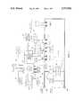
- FIG. 1is a simplified block schematic of the monitoring and control circuit for the apparatus of the present invention
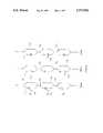
- FIG. 2shows a battery chain of several modules in various bypass configurations in keeping with another feature of the present invention
- FIG. 3is a schematic of a battery module in keeping with a further provision of the present invention.
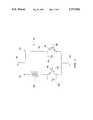
- FIG. 4is a circuit showing the arrangement in an electric vehicle whereby an additional storage filter is provided
- FIG. 5shows an alternative circuit whereby one or other current interruption switches are provided in the traction circuit of an electric vehicle embodying the present invention
- FIG. 6shows representative current and voltage curves when current flowing through the battery is reduced, and from which resistance free voltage in the battery may be extrapolated
- FIG. 7shows yet another embodiment of the traction circuit of an electric vehicle embodying the present invention, wherein an additional load resistor and switch are provided;
- FIG. 8shows current and voltage curves for extrapolating the resistance free voltage of the battery when the circuit of FIG. 5 is operated
- FIG. 9shows typical current and voltage traces as several readings are taken before, during, and after, a diagnostic pulse
- FIG. 10shows a current pulse where a plurality of readings are taken just prior to, at the initiation of, and following, a diagnostic pulse
- FIG. 11shows typical charge acceptance and discharge ability curves, and typical controlled discharge and regenerative braking charge curves, for a long chain battery in an electric vehicle.
- FIGS. 1 through 11Reference will now be made to FIGS. 1 through 11.
- FIG. 1a simplified block schematic of the monitoring and control apparatus of the present invention, installed in an electric vehicle, is shown.
- the circuit 10comprises a long chain battery 12, which is configured with a plurality of series connected cells or battery modules 14.
- a main control module 16is provided, and a plurality of battery monitoring modules 18 is also provided.
- the main control module 16includes operating components such as a voltage reading means (not shown) for receiving and storing voltage information from each of the battery monitoring modules 18, timing means (not shown), microprocessor means (not shown), annunciator means (not shown), a battery monitoring module control means (not shown) by which each of the battery monitoring modules 18 may be controlled, and a temperature monitoring means (not shown).
- a voltage reading meansfor receiving and storing voltage information from each of the battery monitoring modules 18, timing means (not shown), microprocessor means (not shown), annunciator means (not shown), a battery monitoring module control means (not shown) by which each of the battery monitoring modules 18 may be controlled, and a temperature monitoring means (not shown).
- a serial communications bus 24communicates with the main control module 16, and to each battery monitoring module at 26.
- the main control module 16 and the battery monitoring modules 18are in communication with one another over the serial communications bus 24.
- the data acquisition circuitry within each of the battery monitoring modules 18is galvanically isolated from the serial communications bus 24.
- the electric vehicle(not specifically shown) has installed in it the above described circuitry, together with the following circuitry, as shown in FIG. 1.
- the main control module 16includes a vehicle communication bus 30 which provides control, monitoring, and feedback communications to and from a drive controller (not shown) located in the electric vehicle.
- the drive controlleris essentially equivalent to an accelerator in a vehicle that is powered by an internal combustion engine.
- the drive controllercommunicates over the vehicle communications bus with an electric motor 32 and a traction controller 34.
- the electric motor 32 and traction controller 34are connected in series across the battery 12.
- Other vehicle electric loadsare identified generally at 36, and those other electric loads are in parallel with the electric motor 32 and traction controller 34, across the battery.
- the high current wiring for the electric vehicleis shown generally at 38, and it is monitored by a current sensor 40 which communicates with the main control module 16. Also, the high current wiring 38 is connected to a power delivery connector 42a, 42b, which is provided to deliver charging current from a source thereof--such as a charging station of the sort described in U.S. Pat. No. 5,202,617, noted above.
- the power delivery connector 42a, 42b and the electric motor 32are connected to monitoring means therefor which are located within the battery monitoring modules 18, over monitoring wiring 44 and 46, respectively.
- the main control module 16also further includes a charge control interface which may be bifurcated to charging station interface 48 and an on-board charger interface 50.
- the charge control interfacecontrols charging of the battery when it is connected through the charge connector 42a, 42b to a battery charger, in a manner described in any of the NOR or NOR et al patents referenced above.
- An auxiliary data port 52is provided, as may be required; and at least one or more other auxiliary inputs and outputs shown generally at 54, 56, are provided for the main control module 16.
- the auxiliary inputs and outputs 54 and 56are required to monitor and control displays and other electrically operating appliances and auxiliary equipment that are located in the electric vehicle.
- an input 58from an ambient temperature sensor 60 which is mounted in the electric vehicle.
- There may also be one or more other microprocessors and switches within the main control module 16as may be required to monitor and control the input, output, or operation of the other electrically operating appliances and auxiliary equipment, and the external ambient temperature sensor 60.
- Each battery monitoring module 18is provided with at least one or more other auxiliary inputs and outputs 62, which are required to monitor and control any electrically operating appliances or auxiliary circuits or equipment that may be associated with the respective cells or battery modules 14.
- the battery monitoring modules 18further include one or more additional inputs and outputs, also shown at 62, as may be required to connect and control any sensors which are provided to sense cell or battery temperature, or internal cell or battery pressure or electrolyte level, within the modules 14.
- Provision of circuits in keeping with FIG. 1allows for a wide range of DC input voltages which may be brought to the input multiplexer of the electric monitoring system, particulary when the input multiplexer may be such as is taught in U.S. Pat. No. 5,206,578, referenced above.
- cumbersome wiring of all of those DC input voltages to a central pointis essentially eliminated.
- the problems of a wide range of DC input voltages and of cumbersome wiring, and of pick up of noise and interference in such wiringare overcome by the present invention as a consequence of its modularization.
- a typical battery monitoring module 18may have 8 to 16 inputs. Thus, if they are monitoring 8 12-volt modules, or 16 6-volt modules, each battery monitoring module is only monitoring 96 volts of modules 14 within the long chain battery 12. Therefore, the common mode voltage range of an input multiplexer, as noted above, may be kept below 100 to 150 volts.
- the battery monitoring modules 18are advantageously located in proximity to the cells or battery modules 14 with which they are associated. This keeps the lengths of all analog wiring 28 to a minimum.
- Each respective battery monitoring module 38 inputis also capable of monitoring the resistance of the power wiring 38 between the connecting points of two adjacent sensing wires 28.
- all battery current carrying wiring which is external to each module 14is, itself, monitored for changes in resistance or voltage that may occur therein by one or more of the battery monitoring modules 18, through a respective input to such module or modules, then the problems arising in such wiring may be diagnosed and overcome.
- loose, corroded, or otherwise faulty, contacts, particularly in the current carrying wiring 38can be a safety hazard since they may lead to melt-down, electrical arc, and ultimately to fire.
- additional points in the power cablingmay be monitored, beginning at the power delivery connector 42b, 42a, as well as the traction system comprising the electric motor 32 and the traction controller 34, and this may be accomplished by dividing the current carrying wiring 38 into convenient sections for the purposes of monitoring.
- some of the inputs to the individual battery monitoring modulesmay be assigned for those purposes; and thus, resistive drop along those sections of wiring and high or increasing values of resistance therein, will be detected. This will provide early warning of dangerous circumstances developing, and because of the modularization employing a plurality of battery monitoring modules, the location of the incipient danger may be pin-pointed.
- the battery 12is comprised of a long chain of series connected modules 14.
- the capacities of each of the individual modules or cells 14may vary by as much as 5% to 10%.
- the present inventionwill preclude the possibilities of overcharge or overdischarge of any of the individual modules 14. This may be brought about during an equalization charge, which may be performed every 10th to 20th time that the battery 12 is recharged.
- the weaker cells or modules in the batterywill be able to tolerate an extra 5% to 10% of overcharge that they may receive, since this overcharge--which is necessary to bring the highest capacity modules up to full charge condition--is delivered at a relatively low and carefully controlled rate in keeping with the teachings of the NOR or NOR et al battery charging patents referenced above.
- the spread of capacitiesis in the range of 10% to 30%, this is much less favourable to precluding overcharge or overdischarge simply by providing equalization charges every 10th to 20th cycle.
- the present state of manufacturing of batteriesis such that differences of capacities in the range of 10% to 30% may occur during the battery life, and may not be possible to overcome. If so, then the better quality modules in the battery may be underutilized in operating, to the same extent by which they exceed the capacities of the weaker modules.
- the present inventionprovides a switching scheme by which any fully charged or fully discharged module 14 may be bypassed, without comprising the overall ability of the battery 12 to accept charge or to deliver full current. Of course, if individual modules are bypassed, then the battery system voltage will be reduced.
- the present inventionprovides a solution whereby incalculable, or in some cases irreversible, damage to the battery 12 might be prevented.
- Each module K, L, and Mhas a high capacity single pole, double throw switch 70.
- a cell or battery 72is provided for each module, and a bypass current conductor 74 is also provided for each module.
- One throw 71 of each single pole, double throw switch 70is connected to a first end of each cell or battery 72--in this case, shown at the positive end of each cell or battery 72.
- the other or negative side of each cell or battery 72is connected to the common point 75 of the next single pole, double throw switch in the series connection of the long chain battery.
- Each bypass current conductor 74is also connected to the common point 75 of the next series connected single pole, double throw switch 70.
- FIG. 2(a)no battery in any module K, L, or M, is bypassed; in FIG. 2(b), the battery 72 in module K is bypassed; and in FIG. 2(c), all of the batteries are bypassed.
- each of the positive ends of the battery 72are isolated, and the overall battery voltage in the string of modules K, L, and M, is zero volts.
- the highest voltage occurring anywhere in the battery compartment, or should any of the battery modules be dislodged,is the voltage of the single module. This substantially precludes any danger of electrical arc or battery fire occurring.
- Each of the single pole, double throw switches 70may be a mechanical switch or a solid state, semiconductor switch. In any event, as discussed above, each of the switches 70 is galvanically isolated from the respective battery monitoring module 18.
- mechanical switchesare used, there may be losses of, say, 1% to 3% of the battery energy, depending on the design and particular type of mechanical switch that is being utilized. However, there may be the problem of contact reliability and wear. In order to minimize substantive damage to the contacts in the mechanical switches, it may be arranged that they are operated and switched from one pole to the other, or they may be timed to operate, only when the battery current is interrupted or when it is at or near zero.
- a typical module 76is shown. That module is configured as a two-terminal module having terminals 78 and 80, and sides 82 and 84.
- a cell or battery 85is provided which is in series with a parallel connection of a first semiconductor switch 86 and a free wheeling diode 88.
- the free wheeling diodeis forward facing, with respect to the polarity of the cell or battery 85.
- Side 84comprises a bypass conductor 90 in series with a further semiconductor switch 92 in parallel with a further free wheeling diode 94.
- free wheeling diode 94is rearward facing, having regard to the polarity of battery or cell 85.
- switches 86 and 92may be galvanically isolated such as by optocoupler (not shown), or otherwise, from the respective battery monitoring module 18 to which the module 76 is connected.
- the switches 86 and 92may be MOSFETs, or more particularly they may be IGBTs (Isolated Gate Bipolar Transistor) as shown at 96. IGBTs provide low voltage isolation, and are capacitively coupled.
- FIGS. 4 through 8various methods for determining the internal electrochemical potential of battery 12 or any battery module 14, in keeping with the present invention, are now discussed.
- the charge currentis periodically interrupted, such as under the control of the charging station interface or on-board charger interface 48 or 50.
- the electric vehiclemay be configured that no necessary loads are connected to the battery 12; it being possible that clocks, on-board computers, cellular phones, system monitoring devices, and the like, may be separately powered from an auxiliary SLI battery installed in the electric vehicle.
- SLI batterymay be, for example, a standard automobile battery.
- a parallel connection of a high current capacity switch 100 and a rearward facing diode 102is provided in series with the electric motor 32 and traction controller 34.
- a free wheeling diode 104is provided in parallel with the motor 32 and traction controller 34.
- the switch 100is galvanically isolated, as at 106, from the main control module 16.
- An energy storage filtercomprising an inductor 108 in series with switch 100, or a capacitor 110 in parallel with the free wheeling diode 104, or both, is provided.
- the current capacity of switch 100must be such as to be able to carry the maximum battery current rated for the battery 12 and electric vehicle--for example, 500 amperes.
- the free wheeling diode 104must have the same rating so as to smooth the switching transient.
- the switch 100is opened periodically. Because the motor 32 is under load, it will present only a small inductive load component, and the motor current through it will cease for a few milliseconds. Since repeated diagnostic interruptions, even if they are only in the order of from 5 to 10 milliseconds, might be heard and/or felt by the occupants of the electric vehicle, the energy storage filter is provided, as shown in the embodiment of FIG. 4. Thus, when the switch 100 is opened, and if it is opened for a diagnostic period of time which is less than the time constant of the energy storage filter 110, 108, energy will continue to be fed to the electric motor 32. At that time, however, a resistance free voltage reading of the battery, or each cell or battery module therein, can be taken.
- a further method for taking resistance free voltage readingsis contemplated in the traction circuit of the electric vehicle essentially as illustrated in FIG. 1.
- the traction controller 34may be controlled in such a manner that the instantaneous current flowing through the battery 12 can be reduced by controlling the traction controller 34 whereby the electric motor 32 will draw from zero to about 50% of the current flowing through the electric motor just prior to a diagnostic period. That diagnostic period may be from about 3 to about 10 milliseconds. However, as the motor current is reduced even to zero, additional current is still being drawn by other loads such as lights, heating, or air conditioning. In any event, a current reading of current through the long chain battery 12 is made during the diagnostic period.
- the voltage curve 126shows the voltage level increasing from a first level V 1 at 128 to a second voltage level V 2 shown at 130.
- V 1 at 128a first level
- V 2a second voltage level
- the torque delivered by the motormay be specifically altered or notched, in pulses, such as by bringing the battery current to half the full load current; or the battery current may be reduced to zero such as by generating a negative motor current, which is equal in magnitude to the current drawn by the other electrical loads 36.
- a further method of determining resistance free voltage V RFis also to be determined with reference to FIG. 5.
- a further parallel connection of switch 112 and rearward facing diode 114is provided in series with the other vehicle electrical loads 36, beyond the series connected electric motor 32 and traction controller 34.
- the switch 112is galvanically isolated from the main control module 16. In this case, only switch 112 is operated; and the method calls for reading the instantaneous current flowing through the battery 12, periodically interrupting the control of current to the other loads 36 by opening switch 112 for a diagnostic period of time, and taking a current reading of current through the battery 112, while switch 112 is open.
- switch 100is not controlled, and remains closed at all times. The current readings just prior to the diagnostic period of time, and during the diagnostic period of time, are again compared, and the resistance free voltage V RF is mathematically extrapolated in the manner described above.
- the current through switch 112may be considerably lighter than the current through motor 32; and accordingly, the accuracy of the measurements taken because the interrupted current may be small in relation to the total current, is compromised.
- FIG. 7where a further load resistor 146 and a relatively high current capacity switch 148 are provided in series, and they are then provided in parallel with the series connected electric motor 32 and traction controller 34.
- the switch 118is galvanically isolated from the main control module 16.
- the instantaneous current flowing through the battery 12is read, and periodically the switch 148 is closed for a diagnostic period of time. While switch 148 is closed, a current reading of current through the long chain battery 12 is again taken. Once again, the current reading taken just prior to closing the switch 148 and the current reading taken during the diagnostic period while switch 148 is closed are compared; and by mathematic extrapolation, the resistance free voltage V RF may be determined with greater accuracy. This greater accuracy is shown with reference to FIG. 8. Here, a current trace 150 and a voltage trace 152 are shown. The steady state current I, is shown at 154, and the instantaneous current I 2 , which flows when switch 148 is closed, is shown at 156.
- V 1depresses to voltage V 2 , shown at 160, during the diagnostic pulse.
- V 2depresses to voltage V 2 , shown at 160, during the diagnostic pulse.
- the zero current position 162, for I 0can be extrapolated, as can the voltage V 0 at 164, using the following expressions, where I 0 equals zero, V 0 equals V RF , and where (I 2 -I 1 ) equals ⁇ I: ##EQU2##
- the switch 148is turned on for a diagnostic period of, say, 10 milliseconds, whereby the total battery current is raised from I 2 to I 2 .
- the resistance free voltage V RFmay be obtained by extrapolation from values V 1 and V 2 , using linear extrapolation due, once again, to Ohm's law.
- the pulse magnitude of current pulse 166might be comparable to the traction current-in other words, the value of 12 may be approximately twice the value of I 1 --and thus reliable and accurate determinations may be made since the magnitudes of current are appreciable.
- imposition of the diagnostic pulse 166should be rendered undetectable by the driver of the vehicle, and the occupants of the vehicle.
- the vehiclehas a 30 kWh battery which operates with an average power draw of 15 kW, and then a diagnostic pulse of a further 15 kW is imposed, that pulse might be 75 amperes at 200 volts. If the width of pulse 166 is 10 milliseconds, and it is repeated every 10 to 30 seconds, or even every 5 to 30 seconds, then the average power draw will generally be no more than about 15 watts.
- the resistor 146 and the switch 148must be dimensioned for the maximum current of, say, 75 amperes, the power dissipation will only be 15 watts. Thus, both the resistor 146 and the switch 148 may be quite small and inexpensive. Moreover, the resistor 146 may be added to the vehicle heater, so that any heat generated thereby is projected into the cab of the electric vehicle when heating is used.
- FIGS. 9 and 10the following discussion is directed to improvements whereby more accurate voltage or current readings may be taken.
- the electrochemical processestypically have time constants in the order of about 0.5 seconds. Thus, several seconds may be needed to reach an equilibrium or steady state in the event that a change occurs. Readings taken during, or soon after, disturbances of this steady state equilibrium of the battery, such as those taken when there are sudden changes of the accelerator or brake pedal positions, or other loads changes, must be discarded.
- FIG. 9shows typical current and voltage curves 180 and 182.
- three readingsare taken at identical time intervals "t". Readings i 1 and v 1 are taken just before the diagnostic pulse shown in either FIG. 6 or 8; readings i 2 and v 2 are taken just before the end of the diagnostic pulse; and readings i 3 and v 3 are taken after a further time interval "t" which occurs after the diagnostic pulse. From these values, particularly with respect to the methods employed in keeping with FIGS. 7 and 8 above, the values of I 1 , I 2 , V 1 , and V 2 may be determined in keeping with the following relationships: ##EQU3##
- the readings that are taken in those circumstancesmay be discarded because they are not indicative of true electrochemical potential of the electrical charge or discharge reaction taking place in the battery 12.
- each of the three readings shown in curves 180 and 182may be determined by taking several discrete readings within short time intervals of, say, between 5% to 20% of the interval "t"; for example, 4 to 16 readings over 1 to 2 milliseconds. Those readings may then be digitally filtered and averaged so as to achieve high noise rejection and accuracy. Using this three point method, readings taken during a sudden change in load current may be precluded or discarded.
- curve 190shows two series of readings indicated generally at 192 and 194, and taken during two different intervals T. Those intervals may be from 5 to 30 seconds long, typically about 10 seconds, and in each interval T, a series of 2 to 10 readings may be taken in the 2 to 4 seconds that just precede the initiation of each diagnostic pulse as indicated at 196. Each of the readings in the series of readings are compared one to another.
- each of the series of readingsfalls within a predetermined range, such as 198, or if it is assumed that the slope of range 198 may gently rise or fall so that each succeeding reading may be either higher or lower than the preceding reading within a predetermined range, then in any event the readings are accepted because they are indicative of equilibrium of the electrical charge or discharge reaction that is ongoing in the long chain battery 12 during that interval T.
- a predetermined rangesuch as 198
- the readingsare within a range 200, then the readings are rejected.
- the present inventionprovides means for preventing overcharge or overdischarge, as well as providing a better "fuel gauge" for the electric vehicle.
- a characteristic charge acceptance curve 210, and a characteristic discharge ability curve 212can be determined for the long chain battery 12.
- Each of curves 210 and 212is a plot of battery current related to the state of charge of the battery. If the battery is operated above curve 210, it is in overcharge conditions; and if the battery is operated above curve 212, it is in overdischarge conditions.
- curve 214As the vehicle is being driven, the operating point of battery current versus state of charge must remain below curve 214.
- the flat portion of curve 214is arbitrarily determined, but is established so as to permit acceptable operation of the vehicle without causing damage to the battery.
- the current drawn from the batteryis primarily controller limited, for example, to no greater than 300 amperes.
- curve 212will be intersected at point 215, and the monitoring and control functions and circuits within the main control module 16 will cause the current to be limited progressively downwardly.
- a "low fuel” warningmay be annunciated on the dashboard of the vehicle.
- the discharge ability of the batterydrops to a predetermined limit, such as at point 217 on curve 212--at 100 amperes, for example--a further annunciation will flash on "fuel gauge" that the battery 12 is effectively empty.
- the driving timemay be limited to a short period of time--say, 60 seconds to several minutes--and finally, the traction system and other major loads on the battery may be disabled.
- regenerative currentmay be limited by the traction controller to 400 amperes up to about 70% the state of charge, and then progressively limited down to zero amperes at about 90% state of charge of the battery.
- regenerative charging currentis limited to no greater than the maximum allowable; and it is continuously monitored so that when the state of charge approaches the predetermined level at point 219 (70% state of charge), which is just less than the point at which the charge acceptance curve 210 would be intercepted by the maximum allowed regenerative charging current, the regenerative charging current is controlled as at 218 to always stay below the charge acceptance curve 210 as the state of charge of the battery increases.
- the charge and discharge ampere-hours accepted by the battery and delivered by itare integrated, in keeping with the present invention, between the end points which are representative of "EMPTY"--at, for example, 10% state of charge--and “FULL”--at 100% state of charge.
- a determination of the state of charge from cell voltages or electrochemical potentialsmay be unreliable, but the integrating method in keeping with the present invention, and the application of a mathematical model, which applies corrections for the battery temperature and current, and assumes predetermined values of charge efficiency, so that controlled charge and discharge are not damaging to the battery.
- Cumulative errorsmay be eliminated at the FULL point, when it is reached on equalization charge every 10 or 20 charge/discharge cycles, and then scale correction may be applied when the LOW FUEL or EMPTY points are reached.
- Accuracy of the integrity methodcan be further enhanced by calculating the amount of self-discharge of the battery in the standby mode (when the vehicle is not in use), from the self-discharge rate of the given battery, with or without temperature correction, and length of time. This implies that the battery energy monitoring circuitry must operate--with very low power demand--even when the vehicle is not used.
Landscapes
- Engineering & Computer Science (AREA)
- Power Engineering (AREA)
- Transportation (AREA)
- Mechanical Engineering (AREA)
- Life Sciences & Earth Sciences (AREA)
- Sustainable Development (AREA)
- Sustainable Energy (AREA)
- Physics & Mathematics (AREA)
- General Physics & Mathematics (AREA)
- Charge And Discharge Circuits For Batteries Or The Like (AREA)
- Electric Propulsion And Braking For Vehicles (AREA)
- Secondary Cells (AREA)
Abstract
Description
Claims (15)
Priority Applications (1)
| Application Number | Priority Date | Filing Date | Title |
|---|---|---|---|
| US08/841,455US5773962A (en) | 1995-01-17 | 1997-04-22 | Battery energy monitoring circuits |
Applications Claiming Priority (2)
| Application Number | Priority Date | Filing Date | Title |
|---|---|---|---|
| US08/372,936US5670861A (en) | 1995-01-17 | 1995-01-17 | Battery energy monitoring circuits |
| US08/841,455US5773962A (en) | 1995-01-17 | 1997-04-22 | Battery energy monitoring circuits |
Related Parent Applications (1)
| Application Number | Title | Priority Date | Filing Date |
|---|---|---|---|
| US08/372,936DivisionUS5670861A (en) | 1995-01-17 | 1995-01-17 | Battery energy monitoring circuits |
Publications (1)
| Publication Number | Publication Date |
|---|---|
| US5773962Atrue US5773962A (en) | 1998-06-30 |
Family
ID=23470241
Family Applications (2)
| Application Number | Title | Priority Date | Filing Date |
|---|---|---|---|
| US08/372,936Expired - LifetimeUS5670861A (en) | 1995-01-17 | 1995-01-17 | Battery energy monitoring circuits |
| US08/841,455Expired - LifetimeUS5773962A (en) | 1995-01-17 | 1997-04-22 | Battery energy monitoring circuits |
Family Applications Before (1)
| Application Number | Title | Priority Date | Filing Date |
|---|---|---|---|
| US08/372,936Expired - LifetimeUS5670861A (en) | 1995-01-17 | 1995-01-17 | Battery energy monitoring circuits |
Country Status (5)
| Country | Link |
|---|---|
| US (2) | US5670861A (en) |
| EP (1) | EP0750804A1 (en) |
| AU (1) | AU4381596A (en) |
| CA (1) | CA2184578C (en) |
| WO (1) | WO1996022625A1 (en) |
Cited By (192)
| Publication number | Priority date | Publication date | Assignee | Title |
|---|---|---|---|---|
| US5898291A (en)* | 1998-01-26 | 1999-04-27 | Space Systems/Loral, Inc. | Battery cell bypass topology |
| WO2001024306A1 (en)* | 1999-09-28 | 2001-04-05 | Telcordia Technologies, Inc. | Battery power system |
| US6294886B1 (en)* | 1998-08-28 | 2001-09-25 | Alstom France Sa | Supply system for an electric traction vehicle |
| US6411912B1 (en) | 1999-07-09 | 2002-06-25 | Alcatel | Voltage level bus translator and safety interlock system for battery modules |
| US6417668B1 (en) | 2001-01-31 | 2002-07-09 | International Truck International Property Company, L.L.C. | Vehicle battery condition monitoring system |
| US6439510B1 (en)* | 1999-10-29 | 2002-08-27 | Astrium Sas | Electrical energy management and attitude control system for a satellite |
| WO2002021662A3 (en)* | 2000-09-04 | 2002-10-03 | Invensys Energy Systems Nz Ltd | Battery monitoring network |
| US20030038611A1 (en)* | 2000-03-06 | 2003-02-27 | Richard Morgan | Rechargeable batteries |
| US20030087148A1 (en)* | 2001-11-06 | 2003-05-08 | Panasonic Ev Energy Co., Ltd. | Method and apparatus for controlling cooling and detecting abnormality in battery pack system |
| WO2003004315A3 (en)* | 2001-06-29 | 2003-06-26 | Bosch Gmbh Robert | Devices and/or methods for determining the availability of electric energy, particularly in vehicle electric systems comprising several energy accumulators |
| US20030135313A1 (en)* | 2000-06-26 | 2003-07-17 | Rolf Bruck | Configuration and method for switching off at least one stationary-vehicle current apparatus |
| US6631960B2 (en)* | 2001-11-28 | 2003-10-14 | Ballard Power Systems Corporation | Series regenerative braking torque control systems and methods |
| DE20220547U1 (en) | 2001-09-03 | 2003-10-16 | Gpe Internat Ltd | Intelligent, serial battery charger and charging block |
| US20040036475A1 (en)* | 2000-09-04 | 2004-02-26 | Pascoe Phillip Enwood | Battery monitoring |
| US20040100225A1 (en)* | 2002-11-20 | 2004-05-27 | Neil Robert Miles | Cooling and control system for battery charging |
| EP1096636A3 (en)* | 1999-10-25 | 2004-06-30 | Matsushita Electric Industrial Co., Ltd. | Battery pack controlling apparatus |
| EP1122854A3 (en)* | 2000-02-07 | 2004-09-08 | Hitachi, Ltd. | Power storage device and method of measuring voltage of storage battery |
| EP1215795A3 (en)* | 2000-12-13 | 2004-11-10 | Nissan Motor Company, Limited | Apparatus for and method of detecting charge state of vehicle battery |
| US20040222769A1 (en)* | 2001-05-14 | 2004-11-11 | Adnan Al-Anbuky | Stress management of battery recharge and method of state charge estimation |
| US6822423B2 (en) | 2001-09-03 | 2004-11-23 | Gpe International Limited | Intelligent serial battery charger and charging block |
| US20050001627A1 (en)* | 2003-07-01 | 2005-01-06 | Anbuky Adnan H. | Apparatus, methods and computer program products for estimation of battery reserve life using adaptively modified state of health indicator-based reserve life models |
| US20050083016A1 (en)* | 2001-09-03 | 2005-04-21 | Gpe International Limited | Intelligent serial battery charger |
| US6924622B1 (en) | 1999-06-03 | 2005-08-02 | Invensys Energy Systems (Nz) Limited | Battery capacity measurement |
| US20050194937A1 (en)* | 2004-03-08 | 2005-09-08 | Electrovaya Inc. | Battery controller and method for controlling a battery |
| EP1319556A4 (en)* | 2000-09-18 | 2005-10-05 | Sanyo Electric Co | Control system and method for battery control unit |
| US20060139008A1 (en)* | 2004-11-29 | 2006-06-29 | Park Tae H | Protective circuit of battery pack |
| WO2006020877A3 (en)* | 2004-08-12 | 2006-07-13 | Enerdel Inc | Method for cell balancing for lithium battery systems |
| US20060226811A1 (en)* | 2005-04-07 | 2006-10-12 | Se-Wook Seo | Battery management system and driving method thereof |
| US20070018613A1 (en)* | 2001-08-29 | 2007-01-25 | Hideki Miyazaki | Battery apparatus for controlling plural batteries and control method of plural batteries |
| US20070024242A1 (en)* | 2005-07-29 | 2007-02-01 | Se-Wook Seo | Battery management system and driving method thereof |
| US20070080662A1 (en)* | 2005-10-11 | 2007-04-12 | Deping Wu | Universal battery module and controller therefor |
| US20070090803A1 (en)* | 2005-10-20 | 2007-04-26 | Han-Seok Yun | Method of estimating state of charge for battery and battery management system using the same |
| US20070090798A1 (en)* | 2005-10-20 | 2007-04-26 | Han-Seok Yun | Battery management system and battery management method |
| US20070096683A1 (en)* | 2005-03-31 | 2007-05-03 | Hitachi, Ltd. | Electric Motor Driving System, Electric Four-Wheel Drive Vehicle, and Hybrid Vehicle |
| EP1468863A3 (en)* | 2003-04-17 | 2007-11-14 | Howaldtswerke-Deutsche Werft GmbH | Device and method of monitoring an electric battery in a submarine |
| CN100365907C (en)* | 2002-09-26 | 2008-01-30 | 伊顿动力品质有限公司 | Module battery management device with battery perception and electric energy redistribution function |
| US20080091364A1 (en)* | 2006-10-16 | 2008-04-17 | Gye-Jong Lim | Battery Management System (BMS) and driving method thereof |
| US20080091363A1 (en)* | 2006-10-12 | 2008-04-17 | Gye-Jong Lim | Battery Management System (BMS) and driving method thereof |
| US20080100268A1 (en)* | 2006-11-01 | 2008-05-01 | Gye-Jong Lim | Battery management system and driving method thereof |
| FR2912265A1 (en)* | 2007-02-06 | 2008-08-08 | Batscap Sa | BATTERY WITH SERIES CELL MODULES, AND VEHICLE EQUIPPED WITH SAME |
| US20080224709A1 (en)* | 2006-09-26 | 2008-09-18 | Yong-Jun Tae | Battery management system and driving method thereof |
| US20080231232A1 (en)* | 2007-03-19 | 2008-09-25 | Se-Wook Seo | Battery pack |
| US7454273B2 (en) | 2004-08-20 | 2008-11-18 | Harman International Industries, Incorporated | Informed memory access for vehicle electronic modules |
| CN100434303C (en)* | 2003-12-29 | 2008-11-19 | 居永明 | Electric Vehicles with Centralized Processors |
| US20080315830A1 (en)* | 2000-03-27 | 2008-12-25 | Bertness Kevin I | Electronic battery tester or charger with databus connection |
| US20080316752A1 (en)* | 2006-12-12 | 2008-12-25 | David Richard Kostuch | Clarifying filter |
| US20090024266A1 (en)* | 2007-07-17 | 2009-01-22 | Bertness Kevin I | Battery tester for electric vehicle |
| US20090085571A1 (en)* | 2000-03-27 | 2009-04-02 | Bertness Kevin I | Battery testers with secondary functionality |
| KR100908466B1 (en)* | 2005-06-27 | 2009-07-21 | 델피 테크놀로지스 인코포레이티드 | Connection unit for connecting electrical components to the car battery |
| WO2009106394A1 (en)* | 2008-02-25 | 2009-09-03 | Robert Bosch Gmbh | Protection system for battery modules |
| US20090252994A1 (en)* | 2008-04-04 | 2009-10-08 | Alexander Livingston | Battery pack system |
| US20100001694A1 (en)* | 2005-09-08 | 2010-01-07 | Samsung Sdi Co., Ltd. | Control signal generation circuit and battery management system using the same |
| US20100007311A1 (en)* | 2007-02-06 | 2010-01-14 | Batscap | Battery module, pack of modules |
| US20100013489A1 (en)* | 1999-11-01 | 2010-01-21 | Vonderhaar J David | Electronic battery tester |
| WO2010022999A1 (en)* | 2008-08-25 | 2010-03-04 | Robert Bosch Gmbh | Monitoring system for an accumulator |
| US20100090659A1 (en)* | 2007-02-06 | 2010-04-15 | Batscap | Power battery module, battery, module charging method, vehicle having the battery |
| WO2010042517A1 (en)* | 2008-10-07 | 2010-04-15 | Boston-Power, Inc. | Li-ion battery array for vehicle and other large capacity applications |
| US20100108291A1 (en)* | 2008-09-12 | 2010-05-06 | Boston-Power, Inc. | Method and apparatus for embedded battery cells and thermal management |
| US20100164436A1 (en)* | 2005-07-14 | 2010-07-01 | Boston-Power, Inc. | Control Electronics for Li-ion Batteries |
| US20100194576A1 (en)* | 1997-11-03 | 2010-08-05 | Bertness Kevin I | Electronic battery tester with network communication |
| WO2010088998A1 (en)* | 2009-02-06 | 2010-08-12 | Robert Bosch Gmbh | More readily available traction battery |
| WO2010088999A1 (en)* | 2009-02-06 | 2010-08-12 | Robert Bosch Gmbh | More readily available traction battery |
| US20100250043A1 (en)* | 2006-02-09 | 2010-09-30 | Scheucher Karl F | Refuelable battery-powered electric vehicle |
| US7812613B2 (en) | 2003-06-12 | 2010-10-12 | Philadelphia Scientific | System and method for monitoring electrolyte levels in a battery |
| US20100289457A1 (en)* | 2009-05-18 | 2010-11-18 | Boston-Power, Inc. | Energy efficient and fast charge modes of a rechargeable battery |
| US20100305792A1 (en)* | 2009-05-29 | 2010-12-02 | Ise Corporation | Dynamically Reconfigurable High Power Energy Storage for Hybrid Vehicles |
| US20110001442A1 (en)* | 2009-07-02 | 2011-01-06 | Chong Uk Lee | Electric bicycle drive system with regenerative charging |
| US20110022281A1 (en)* | 2006-12-22 | 2011-01-27 | Eberhard Boehl | Vehicle-supported data processing system |
| US20110031051A1 (en)* | 2009-07-17 | 2011-02-10 | Albert Donald George | Rechargeable electric vehicle with extended driving range, and method of converting vehicle with internal combustion (IC) engine to rechargeable electric vehicle |
| US20110049977A1 (en)* | 2009-09-01 | 2011-03-03 | Boston-Power, Inc. | Safety and performance optimized controls for large scale electric vehicle battery systems |
| US20110115434A1 (en)* | 2006-06-28 | 2011-05-19 | Boston-Power, Inc. | Electronics with multiple charge rate |
| WO2011076257A1 (en)* | 2009-12-22 | 2011-06-30 | Abb Research Ltd. | Battery energy storage system with short circuit protection, and method |
| US20110213509A1 (en)* | 2009-09-01 | 2011-09-01 | Boston-Power, Inc. | Large scale battery systems and method of assembly |
| US20110218747A1 (en)* | 2010-03-03 | 2011-09-08 | Bertness Kevin I | Monitor for front terminal batteries |
| DE102010027861A1 (en)* | 2010-04-16 | 2011-10-20 | Sb Limotive Company Ltd. | Coupling unit and battery module with integrated pulse inverter and exchangeable cell modules |
| WO2012038154A1 (en)* | 2010-09-20 | 2012-03-29 | Sb Limotive Company Ltd. | Method for starting up a battery system having a dc voltage intermediate circuit |
| WO2011121543A3 (en)* | 2010-03-29 | 2012-03-29 | Antoine Juan | Autonomous motorization system |
| US20120086400A1 (en)* | 2010-10-06 | 2012-04-12 | White David A | Module Bypass Switch for Balancing Battery Pack System Modules |
| WO2012049572A1 (en)* | 2010-10-14 | 2012-04-19 | Sendyne Corp. | Reliable signaling of fault conditions in battery systems with series-connected cells |
| US8164343B2 (en) | 2003-09-05 | 2012-04-24 | Midtronics, Inc. | Method and apparatus for measuring a parameter of a vehicle electrical system |
| US20120105001A1 (en)* | 2010-09-02 | 2012-05-03 | Proterra Inc. | Systems and methods for battery management |
| US8198900B2 (en) | 1996-07-29 | 2012-06-12 | Midtronics, Inc. | Automotive battery charging system tester |
| US8203345B2 (en) | 2007-12-06 | 2012-06-19 | Midtronics, Inc. | Storage battery and battery tester |
| US20120161713A1 (en)* | 2010-12-22 | 2012-06-28 | Electronics And Telecommunications Research Institute | Vehicle energy harvesting apparatus and energy management method thereof |
| WO2012095202A1 (en)* | 2011-01-13 | 2012-07-19 | Sb Limotive Company Ltd. | Battery management unit comprising a plurality of monitoring units |
| EP2442384A3 (en)* | 2010-10-14 | 2012-07-25 | Alliant Techsystems Inc. | Methods and apparatuses for electrochemical cell monitoring and control |
| WO2012134870A1 (en)* | 2011-04-01 | 2012-10-04 | Continental Automotive Systems, Inc. | Estimating the capacity of a li-ion battery based on initial part of the discharge curve |
| WO2012062255A3 (en)* | 2010-11-02 | 2012-11-01 | Voltabatterien Gmbh | Inherently safe modular battery for accident-prone applications |
| US20120299529A1 (en)* | 2009-12-31 | 2012-11-29 | Guo Guangxi | Solar charger for charging power battery |
| US8344685B2 (en) | 2004-08-20 | 2013-01-01 | Midtronics, Inc. | System for automatically gathering battery information |
| EP2543534A1 (en)* | 2011-07-08 | 2013-01-09 | Siemens Aktiengesellschaft | Energy storage device with improved security, automobile with a respective energy storage device and method for operating an energy storage device |
| ITTO20110614A1 (en)* | 2011-07-13 | 2013-01-14 | Bitron Spa | BATTERY PACKAGE SAFETY SYSTEM. |
| WO2012089395A3 (en)* | 2010-12-29 | 2013-03-28 | Robert Bosch Gmbh | Controllable energy store and method for operating a controllable energy store |
| WO2012089397A3 (en)* | 2010-12-29 | 2013-04-18 | Robert Bosch Gmbh | System for coupling at least one ac power source to a controllable energy store and associated operational method |
| US8436619B2 (en) | 2004-08-20 | 2013-05-07 | Midtronics, Inc. | Integrated tag reader and environment sensor |
| US8442877B2 (en) | 2004-08-20 | 2013-05-14 | Midtronics, Inc. | Simplification of inventory management |
| WO2013086627A1 (en)* | 2011-12-12 | 2013-06-20 | Panacis, Inc. | A system and method for enhancing the cost-efficiency of rechargeable battery systems |
| US8493022B2 (en) | 1997-11-03 | 2013-07-23 | Midtronics, Inc. | Automotive vehicle electrical system diagnostic device |
| DE102012201602A1 (en)* | 2012-02-03 | 2013-08-08 | Robert Bosch Gmbh | Method for adjusting flowing current of strand of battery used in battery system mounted in vehicle, involves actuating two battery modules with different clock frequencies of direct current (DC)/DC transducer |
| WO2012152578A3 (en)* | 2011-05-06 | 2013-08-15 | Robert Bosch Gmbh | Drive unit for an electric motor |
| WO2013045324A3 (en)* | 2011-09-27 | 2013-08-22 | Robert Bosch Gmbh | Communications interface for system monitoring of the energy supply in electric and hybrid vehicles |
| WO2013124079A1 (en)* | 2012-02-24 | 2013-08-29 | Robert Bosch Gmbh | System and method for actuating an energy storage device |
| US20130234667A1 (en)* | 2010-11-25 | 2013-09-12 | Cheevc Ltd | Battery management system and method |
| WO2013064322A3 (en)* | 2011-11-04 | 2014-01-30 | Robert Bosch Gmbh | Battery management unit having a plurality of monitoring ic chips |
| US8674711B2 (en) | 2003-09-05 | 2014-03-18 | Midtronics, Inc. | Method and apparatus for measuring a parameter of a vehicle electrical system |
| US8674654B2 (en) | 1997-11-03 | 2014-03-18 | Midtronics, Inc. | In-vehicle battery monitor |
| US8710801B2 (en) | 2010-09-23 | 2014-04-29 | Stmicroelectronics Application Gmbh | Battery comprising circuitry for charge and discharge control, and method of operating a battery |
| US8738309B2 (en) | 2010-09-30 | 2014-05-27 | Midtronics, Inc. | Battery pack maintenance for electric vehicles |
| US8816613B2 (en) | 2009-07-02 | 2014-08-26 | Chong Uk Lee | Reconfigurable battery |
| EP2221942A3 (en)* | 2009-01-06 | 2014-10-01 | O2 Micro, Inc. | Battery management system |
| US8872517B2 (en) | 1996-07-29 | 2014-10-28 | Midtronics, Inc. | Electronic battery tester with battery age input |
| US8872516B2 (en) | 2000-03-27 | 2014-10-28 | Midtronics, Inc. | Electronic battery tester mounted in a vehicle |
| US8957610B2 (en) | 2009-07-02 | 2015-02-17 | Chong Uk Lee | Multi-port reconfigurable battery |
| US9018958B2 (en) | 2003-09-05 | 2015-04-28 | Midtronics, Inc. | Method and apparatus for measuring a parameter of a vehicle electrical system |
| EP2866326A1 (en)* | 2013-10-21 | 2015-04-29 | Mitsubishi Jidosha Kogyo Kabushiki Kaisha | Battery pack |
| US9085238B2 (en) | 2013-01-11 | 2015-07-21 | Johnson Controls Technology Company | Energy storage control system and method |
| US9114181B2 (en) | 2011-03-30 | 2015-08-25 | Covidien Lp | Process of cooling surgical device battery before or during high temperature sterilization |
| WO2015149994A1 (en)* | 2014-04-02 | 2015-10-08 | Robert Bosch Gmbh | Battery system with a battery for supplying a high-voltage network and at least one switching unit for limiting a residual current flowing across the battery and the high-voltage terminals of the battery and/or for limiting a voltage applied from the battery across the high-voltage terminals of the battery to the high-voltage network and a corresponding method |
| US9201120B2 (en) | 2010-08-12 | 2015-12-01 | Midtronics, Inc. | Electronic battery tester for testing storage battery |
| US9229062B2 (en) | 2010-05-27 | 2016-01-05 | Midtronics, Inc. | Electronic storage battery diagnostic system |
| US9244100B2 (en) | 2013-03-15 | 2016-01-26 | Midtronics, Inc. | Current clamp with jaw closure detection |
| WO2016012546A1 (en)* | 2014-07-24 | 2016-01-28 | Pendix Gmbh | Energy store |
| US20160025795A1 (en)* | 2012-05-07 | 2016-01-28 | Tesla Motors, Inc. | Wire break detection in redundant communications |
| US9255955B2 (en) | 2003-09-05 | 2016-02-09 | Midtronics, Inc. | Method and apparatus for measuring a parameter of a vehicle electrical system |
| US9274157B2 (en) | 2007-07-17 | 2016-03-01 | Midtronics, Inc. | Battery tester for electric vehicle |
| US20160089992A1 (en)* | 2014-09-30 | 2016-03-31 | Johnson Controls Technology Company | Battery system bi-stable relay control |
| US9312575B2 (en) | 2013-05-16 | 2016-04-12 | Midtronics, Inc. | Battery testing system and method |
| US9331484B2 (en) | 2014-03-06 | 2016-05-03 | Nissan North America, Inc. | Systems and methods of controlling battery deterioration by controlling battery temperature during power exchange |
| US9331503B2 (en) | 2014-03-06 | 2016-05-03 | Nissan North America, Inc. | Systems and methods of controlling battery deterioration by controlling battery state-of-health during power exchange |
| US9419311B2 (en) | 2010-06-18 | 2016-08-16 | Midtronics, Inc. | Battery maintenance device with thermal buffer |
| US9496720B2 (en) | 2004-08-20 | 2016-11-15 | Midtronics, Inc. | System for automatically gathering battery information |
| US20160336770A1 (en)* | 2014-01-08 | 2016-11-17 | Robert Bosch Gmbh | Battery management system for monitoring and regulating the operation of a battery and battery system having such a battery management system |
| US9588185B2 (en) | 2010-02-25 | 2017-03-07 | Keith S. Champlin | Method and apparatus for detecting cell deterioration in an electrochemical cell or battery |
| US20170126035A1 (en)* | 2015-11-04 | 2017-05-04 | Johnson Controls Technology Company | Cell control unit fault detection systems and methods |
| US20170210596A1 (en)* | 2014-01-27 | 2017-07-27 | Otis Elevator Company | Charge algorithm for battery propelled elevator |
| EP3213952A1 (en)* | 2016-03-02 | 2017-09-06 | Airbus Defence and Space GmbH | Electric drive system for an aircraft and method of operating same |
| US9851411B2 (en) | 2012-06-28 | 2017-12-26 | Keith S. Champlin | Suppressing HF cable oscillations during dynamic measurements of cells and batteries |
| US9923289B2 (en) | 2014-01-16 | 2018-03-20 | Midtronics, Inc. | Battery clamp with endoskeleton design |
| US9966676B2 (en) | 2015-09-28 | 2018-05-08 | Midtronics, Inc. | Kelvin connector adapter for storage battery |
| US10046649B2 (en) | 2012-06-28 | 2018-08-14 | Midtronics, Inc. | Hybrid and electric vehicle battery pack maintenance device |
| US10099562B2 (en) | 2014-10-15 | 2018-10-16 | Johnson Controls Technology Company | Cooling strategy for battery systems |
| US10222397B2 (en) | 2014-09-26 | 2019-03-05 | Midtronics, Inc. | Cable connector for electronic battery tester |
| US10317468B2 (en) | 2015-01-26 | 2019-06-11 | Midtronics, Inc. | Alternator tester |
| US10429449B2 (en) | 2011-11-10 | 2019-10-01 | Midtronics, Inc. | Battery pack tester |
| US10473555B2 (en) | 2014-07-14 | 2019-11-12 | Midtronics, Inc. | Automotive maintenance system |
| US20200070665A1 (en)* | 2018-08-28 | 2020-03-05 | Ii-Vi Delaware, Inc. | Adaptive Reservoir Charging Station |
| US10608353B2 (en) | 2016-06-28 | 2020-03-31 | Midtronics, Inc. | Battery clamp |
| US10613567B2 (en) | 2013-08-06 | 2020-04-07 | Bedrock Automation Platforms Inc. | Secure power supply for an industrial control system |
| US10628361B2 (en) | 2011-12-30 | 2020-04-21 | Bedrock Automation Platforms Inc. | Switch fabric having a serial communications interface and a parallel communications interface |
| US10824711B2 (en) | 2013-08-06 | 2020-11-03 | Bedrock Automation Platforms Inc. | Secure industrial control system |
| US10834820B2 (en) | 2013-08-06 | 2020-11-10 | Bedrock Automation Platforms Inc. | Industrial control system cable |
| US10834094B2 (en) | 2013-08-06 | 2020-11-10 | Bedrock Automation Platforms Inc. | Operator action authentication in an industrial control system |
| US10833872B2 (en) | 2013-08-06 | 2020-11-10 | Bedrock Automation Platforms Inc. | Industrial control system redundant communication/control modules authentication |
| US10832861B2 (en) | 2011-12-30 | 2020-11-10 | Bedrock Automation Platforms Inc. | Electromagnetic connector for an industrial control system |
| US10848012B2 (en) | 2011-12-30 | 2020-11-24 | Bedrock Automation Platforms Inc. | Electromagnetic connectors for an industrial control system |
| US10843574B2 (en) | 2013-12-12 | 2020-11-24 | Midtronics, Inc. | Calibration and programming of in-vehicle battery sensors |
| US10897145B2 (en)* | 2015-12-29 | 2021-01-19 | Vito Nv | Device and method for the reconfiguration of a rechargeable energy storage device into separate battery connection strings |
| US10896145B2 (en) | 2011-12-30 | 2021-01-19 | Bedrock Automation Platforms Inc. | Communications control system with a serial communications interface and a parallel communications interface |
| US11005276B2 (en) | 2018-01-23 | 2021-05-11 | Solsona Enterprise, Llc | Stacked variable voltage battery module arrangement |
| US11055246B2 (en) | 2011-12-30 | 2021-07-06 | Bedrock Automation Platforms Inc. | Input-output module with multi-channel switching capability |
| US11054480B2 (en) | 2016-10-25 | 2021-07-06 | Midtronics, Inc. | Electrical load for electronic battery tester and electronic battery tester including such electrical load |
| US11084382B2 (en)* | 2017-05-31 | 2021-08-10 | Bayerische Motoren Werke Aktiengesellschaft | Vehicle energy store |
| US11144630B2 (en) | 2011-12-30 | 2021-10-12 | Bedrock Automation Platforms Inc. | Image capture devices for a secure industrial control system |
| WO2021209259A1 (en)* | 2020-04-17 | 2021-10-21 | Renault S.A.S | Method for calibrating a charge current of a battery for an electric motor vehicle |
| JP2022029299A (en)* | 2020-08-04 | 2022-02-17 | 矢崎総業株式会社 | Charge control device, battery system, and charge control method |
| US11314854B2 (en) | 2011-12-30 | 2022-04-26 | Bedrock Automation Platforms Inc. | Image capture devices for a secure industrial control system |
| US11325479B2 (en) | 2012-06-28 | 2022-05-10 | Midtronics, Inc. | Hybrid and electric vehicle battery maintenance device |
| US20220244691A1 (en)* | 2019-06-24 | 2022-08-04 | DD Dannar, LLC | Battery Communication and Control Systems and Methods |
| US11474153B2 (en) | 2019-11-12 | 2022-10-18 | Midtronics, Inc. | Battery pack maintenance system |
| US11486930B2 (en) | 2020-01-23 | 2022-11-01 | Midtronics, Inc. | Electronic battery tester with battery clamp storage holsters |
| US20220360091A1 (en)* | 2021-05-04 | 2022-11-10 | Exro Technologies Inc. | Battery Control Systems and Methods |
| US11513160B2 (en) | 2018-11-29 | 2022-11-29 | Midtronics, Inc. | Vehicle battery maintenance device |
| US11545839B2 (en) | 2019-11-05 | 2023-01-03 | Midtronics, Inc. | System for charging a series of connected batteries |
| US11566972B2 (en) | 2019-07-31 | 2023-01-31 | Midtronics, Inc. | Tire tread gauge using visual indicator |
| US11650259B2 (en) | 2010-06-03 | 2023-05-16 | Midtronics, Inc. | Battery pack maintenance for electric vehicle |
| US11668779B2 (en) | 2019-11-11 | 2023-06-06 | Midtronics, Inc. | Hybrid and electric vehicle battery pack maintenance device |
| US11722026B2 (en) | 2019-04-23 | 2023-08-08 | Dpm Technologies Inc. | Fault tolerant rotating electric machine |
| US11740294B2 (en) | 2010-06-03 | 2023-08-29 | Midtronics, Inc. | High use battery pack maintenance |
| US11955607B2 (en) | 2019-12-23 | 2024-04-09 | Kk Wind Solutions A/S | Monitoring system for an energy storage |
| US11967839B2 (en) | 2011-12-30 | 2024-04-23 | Analog Devices, Inc. | Electromagnetic connector for an industrial control system |
| US11966349B2 (en) | 2011-12-30 | 2024-04-23 | Analog Devices, Inc. | Electromagnetic connector for for an industrial control system |
| US11967913B2 (en) | 2021-05-13 | 2024-04-23 | Exro Technologies Inc. | Method and apparatus to drive coils of a multiphase electric machine |
| US11973202B2 (en) | 2019-12-31 | 2024-04-30 | Midtronics, Inc. | Intelligent module interface for battery maintenance device |
| US12061685B2 (en) | 2011-12-30 | 2024-08-13 | Analog Devices, Inc. | Image capture devices for a secure industrial control system |
| US12088176B2 (en) | 2021-07-08 | 2024-09-10 | Exro Technologies Inc. | Dynamically reconfigurable power converter utilizing windings of electric machine |
| US12120819B2 (en) | 2014-07-07 | 2024-10-15 | Analog Devices, Inc. | Industrial control system cable |
| US12176836B2 (en) | 2018-09-05 | 2024-12-24 | Dpm Technologies Inc. | Systems and methods for intelligent energy storage and provisioning using an energy storage control system |
| US12237482B2 (en) | 2019-12-31 | 2025-02-25 | Midtronics, Inc. | Intelligent module interface for battery maintenance device |
| US12320857B2 (en) | 2016-10-25 | 2025-06-03 | Midtronics, Inc. | Electrical load for electronic battery tester and electronic battery tester including such electrical load |
| US12330513B2 (en) | 2022-02-14 | 2025-06-17 | Midtronics, Inc. | Battery maintenance device with high voltage connector |
| US12392833B2 (en) | 2022-05-09 | 2025-08-19 | Midtronics, Inc. | Electronic battery tester |
| US12434573B2 (en)* | 2021-09-17 | 2025-10-07 | Bayerische Motoren Werke Aktiengesellschaft | Vehicle with an electric energy storage device |
Families Citing this family (102)
| Publication number | Priority date | Publication date | Assignee | Title |
|---|---|---|---|---|
| US6184656B1 (en) | 1995-06-28 | 2001-02-06 | Aevt, Inc. | Radio frequency energy management system |
| US5982643A (en)* | 1996-10-10 | 1999-11-09 | Progressive Dynamics, Inc. | Power converter with selectively variable output and controller and display system therefor |
| US6011379A (en)* | 1997-03-12 | 2000-01-04 | U.S. Nanocorp, Inc. | Method for determining state-of-charge using an intelligent system |
| US6456988B1 (en) | 1997-03-12 | 2002-09-24 | U.S. Nanocorp Inc. | Method for determining state-of-health using an intelligent system |
| JPH1189002A (en) | 1997-09-09 | 1999-03-30 | Matsushita Electric Ind Co Ltd | Vehicle |
| US6094033A (en)* | 1998-10-02 | 2000-07-25 | Georgia Tech Research Corporation | Battery state of charge detector with rapid charging capability and method |
| US6229285B1 (en) | 1997-10-03 | 2001-05-08 | Georgia Tech Research Corporation | Detector for rapid charging and method |
| JP3680898B2 (en)* | 1997-10-13 | 2005-08-10 | トヨタ自動車株式会社 | Secondary battery charge / discharge controller |
| US5869950A (en)* | 1997-10-30 | 1999-02-09 | Lockheed Martin Corp. | Method for equalizing the voltage of traction battery modules of a hybrid electric vehicle |
| ATE362854T1 (en)* | 1997-12-23 | 2007-06-15 | Amerigon Inc | RADIO FREQUENCY ENERGY MANAGEMENT SYSTEM |
| JP3503453B2 (en)* | 1997-12-26 | 2004-03-08 | 株式会社日立製作所 | Battery system and electric vehicle using the same |
| US6420852B1 (en) | 1998-08-21 | 2002-07-16 | Sony Corporation | Battery pack |
| JP3967043B2 (en)* | 1999-09-02 | 2007-08-29 | 日産自動車株式会社 | Control device for hybrid vehicle |
| US6816797B2 (en)* | 2000-09-29 | 2004-11-09 | Hydrogenics Corporation | System and method for measuring fuel cell voltage and high frequency resistance |
| WO2002080332A1 (en)* | 2001-03-30 | 2002-10-10 | Designline Limited | Battery management unit, system and method |
| JP3839761B2 (en)* | 2001-09-14 | 2006-11-01 | 松下電器産業株式会社 | Battery control device |
| DK1570538T3 (en)* | 2002-12-03 | 2017-01-23 | Hydrogenics Corp | Method and Device for Monitoring Fuel Cell Tensions |
| WO2004070343A2 (en)* | 2003-02-04 | 2004-08-19 | Hydrogenics Corporation | System and method for measuring internal resistance of electrochemical devices |
| US7358701B2 (en) | 2003-02-07 | 2008-04-15 | Field Robert B | Method and system for modeling energy transfer |
| US7221125B2 (en)* | 2003-11-06 | 2007-05-22 | Y. Ding | System and method for charging a battery |
| WO2005050332A2 (en)* | 2003-11-17 | 2005-06-02 | Ballard Commercial Industries, Inc. | Improved regulator system for alternator |
| EP1768252B1 (en)* | 2004-07-07 | 2011-01-05 | Hitachi, Ltd. | Motor controlling device for mounting on vehicle |
| US7772852B2 (en)* | 2004-07-21 | 2010-08-10 | C & C Power, Inc. | Battery string performance measurement |
| US7782002B2 (en)* | 2004-09-08 | 2010-08-24 | Progressive Dynamics, Inc. | Power converter |
| US7444192B2 (en) | 2004-10-26 | 2008-10-28 | Aerovironment, Inc. | Reactive replenishable device management |
| US7568538B2 (en)* | 2005-02-02 | 2009-08-04 | Mattel, Inc. | Children's ride-on vehicle charging assemblies with back feed protection |
| JP2006246646A (en)* | 2005-03-04 | 2006-09-14 | Yazaki Corp | Equalizing method and apparatus |
| JP2007043788A (en)* | 2005-08-01 | 2007-02-15 | Yazaki Corp | Method and apparatus for adjusting state of charge of battery pack |
| US7835877B2 (en)* | 2006-02-24 | 2010-11-16 | General Electric Company | Processes and apparatus for battery compensation |
| US20080100259A1 (en)* | 2006-10-26 | 2008-05-01 | Ford Global Technologies, Llc | Service jump-start device for hybrid electric vehicles |
| US8307967B2 (en)* | 2007-07-04 | 2012-11-13 | Satyajit Patwardhan | Widely deployable charging system for vehicles |
| JP5137147B2 (en)* | 2007-07-10 | 2013-02-06 | セイコーインスツル株式会社 | Power supply |
| US8586256B2 (en)* | 2007-07-10 | 2013-11-19 | Seiko Instruments Inc. | Power supply apparatus |
| US8005632B2 (en)* | 2007-11-07 | 2011-08-23 | GM Global Technology Operations LLC | Method and apparatus for detecting faults in a current sensing device |
| JP2011526228A (en) | 2008-06-27 | 2011-10-06 | プロテラ インコーポレイテッド | Vehicle battery system and method |
| US20100006351A1 (en)* | 2008-07-08 | 2010-01-14 | Howard J Scott | Electric vehicle with contra-recgarge system |
| US20100164437A1 (en)* | 2008-10-24 | 2010-07-01 | Mckinley Joseph P | Battery formation and charging system and method |
| FR2944161A1 (en)* | 2009-04-02 | 2010-10-08 | Vehicules Electr Soc D | METHOD FOR SECURING THE OPERATION OF AN ELECTRIC BATTERY |
| US8598846B1 (en)* | 2009-04-07 | 2013-12-03 | The University Of Akron | Device and method for stabilizing a battery pack |
| JP2010257775A (en)* | 2009-04-24 | 2010-11-11 | Sanyo Electric Co Ltd | Battery module, battery system, and electric vehicle |
| US20100291427A1 (en)* | 2009-05-15 | 2010-11-18 | Sinoelectric Powertrain Corporation | Modular powertrain, systems, and methods |
| US20100291418A1 (en)* | 2009-05-15 | 2010-11-18 | Sinoelectric Powertrain Corporation | Battery packs, systems, and methods |
| DE102009034596A1 (en)* | 2009-07-24 | 2011-02-03 | Continental Automotive Gmbh | Electrical energy storing system for e.g. electric vehicle, has switching device connecting compensation cell to storage arrangement, so that difference of potential between storage arrangement and another storage arrangement is minimized |
| FR2951320B1 (en)* | 2009-10-08 | 2011-12-30 | Vehicules Electr Soc D | ELECTRIC BATTERY COMPRISING A PLURALITY OF ELECTRIC POWER GENERATING ELEMENTS |
| DE102009046564A1 (en)* | 2009-11-10 | 2011-05-12 | SB LiMotive Company Ltd., Suwon | Battery control unit architecture |
| DE102010007076A1 (en)* | 2010-02-06 | 2011-08-11 | Fraunhofer-Gesellschaft zur Förderung der angewandten Forschung e.V., 80686 | Electric energy storage |
| EP2355229A1 (en) | 2010-02-08 | 2011-08-10 | Fortu Intellectual Property AG | High voltage battery system and method for controlling same |
| US20110165829A1 (en)* | 2010-02-25 | 2011-07-07 | Ford Global Technologies, Llc | Automotive vehicle and method for operating climate system of same |
| WO2011127319A1 (en) | 2010-04-08 | 2011-10-13 | Sinoelectric Powertrain Inc | Apparatus for preheating a battery pack before charging |
| KR101047831B1 (en)* | 2010-06-17 | 2011-07-08 | 에스케이이노베이션 주식회사 | Safety component by fuse at high voltage battery sensing line |
| DE102010026435B4 (en)* | 2010-07-08 | 2023-01-26 | Vitesco Technologies Germany Gmbh | Device for classifying an electrical contact between two connection elements |
| US9172120B2 (en) | 2010-07-14 | 2015-10-27 | Sinoelectric Powertrain Corporation | Battery pack fault communication and handling |
| US8659261B2 (en) | 2010-07-14 | 2014-02-25 | Sinoelectric Powertrain Corporation | Battery pack enumeration method |
| JP5567956B2 (en)* | 2010-09-16 | 2014-08-06 | 矢崎総業株式会社 | Cell voltage equalization device for multiple assembled batteries |
| DE102010041029A1 (en)* | 2010-09-20 | 2012-03-22 | Sb Limotive Company Ltd. | Method for starting up a battery system with a DC intermediate circuit |
| DE102010041014A1 (en)* | 2010-09-20 | 2012-03-22 | Sb Limotive Company Ltd. | Battery system with variably adjustable intermediate circuit voltage |
| US8641273B2 (en) | 2010-11-02 | 2014-02-04 | Sinoelectric Powertrain Corporation | Thermal interlock for battery pack, device, system and method |
| US8486283B2 (en) | 2010-11-02 | 2013-07-16 | Sinoelectric Powertrain Corporation | Method of making fusible links |
| FI124055B (en)* | 2011-01-21 | 2014-02-28 | Amotec Oy | Method and apparatus for electric motor operation |
| DE102011014133A1 (en)* | 2011-03-15 | 2012-09-20 | Maximilian Heindl | Method for varying e.g. voltage at connection terminals of series circuit of battery cells of heterogeneous battery arrangement in electric car, involves varying configuration of series circuit for adjustment of voltage and impedance |
| DE102011084362B4 (en)* | 2011-03-30 | 2015-03-05 | Bender Gmbh & Co. Kg | Electrical protection and monitoring device in an electric vehicle for safe driving and safe charging and regenerative operation of the electric vehicle at a charging station |
| US20120256583A1 (en)* | 2011-04-08 | 2012-10-11 | Davis Stuart M | Low Cost Fast Charger with Internal Accumulator and Method |
| DE102011075384A1 (en)* | 2011-05-06 | 2012-11-08 | Robert Bosch Gmbh | Battery double module |
| DE102011075421A1 (en)* | 2011-05-06 | 2012-11-08 | Sb Limotive Company Ltd. | Battery with at least one battery module string |
| JP5739244B2 (en)* | 2011-06-14 | 2015-06-24 | 矢崎総業株式会社 | Battery status notification unit, bus bar module, assembled battery, and battery status monitoring system |
| DE102011082941A1 (en)* | 2011-09-19 | 2013-03-21 | Bender Gmbh & Co. Kg | Electrical monitoring device and method for ensuring the protective function of a residual current device (RCD) type A |
| DE102011054479A1 (en)* | 2011-10-13 | 2013-04-18 | Fraunhofer-Gesellschaft zur Förderung der angewandten Forschung e.V. | Energy storage system and method for controlling the charge states of its elements |
| FR2982089B1 (en)* | 2011-10-26 | 2013-11-01 | Renault Sa | METHOD FOR BALANCING THE LEVEL OF CHARGE AND DISCHARGE OF A BATTERY BY SWITCHING ITS BLOCKS OF CELLS |
| DE102011087028A1 (en)* | 2011-11-24 | 2013-05-29 | Sb Limotive Company Ltd. | Battery module string for driving a DC motor |
| US9404956B2 (en)* | 2011-12-19 | 2016-08-02 | Ford Global Technologies, Llc | Vehicle with selectable battery pack isolation detection circuitry using precision resistors |
| DE102011089648A1 (en) | 2011-12-22 | 2013-06-27 | Robert Bosch Gmbh | Energy storage device, system with energy storage device and method for driving an energy storage device |
| DE102012202860A1 (en)* | 2012-02-24 | 2013-08-29 | Robert Bosch Gmbh | An exchangeable energy storage device and method for exchanging an energy storage device |
| DE102012204933A1 (en)* | 2012-03-28 | 2013-10-02 | Robert Bosch Gmbh | Battery system and method for driving battery modules of the battery system |
| WO2014020582A2 (en)* | 2012-08-03 | 2014-02-06 | Suren Martirosyan | Method for providing adjustable power from battery packs, discrete power distribution unit for electric vehicles |
| US10365332B2 (en)* | 2012-11-02 | 2019-07-30 | Analog Devices Global Unlimited Company | System and method to reduce data handling on lithium ion battery monitors |
| DE102012222746A1 (en) | 2012-12-11 | 2014-06-12 | Robert Bosch Gmbh | Battery module balancing and battery management system |
| DE102012223482A1 (en)* | 2012-12-18 | 2014-06-18 | Robert Bosch Gmbh | Battery with at least one battery string and method for controlling a battery voltage |
| KR101397887B1 (en)* | 2013-05-15 | 2014-05-20 | 주식회사 엘지씨엔에스 | Monitoring device and method of battery contact point at the charging/discharging system with serial connected batteries |
| CN103399282B (en)* | 2013-08-07 | 2015-07-29 | 清华大学 | Battery cell method for diagnosing faults |
| US9975434B2 (en)* | 2013-09-24 | 2018-05-22 | Ford Global Technologies, Llc | System and method for monitoring contactor health |
| US9915703B2 (en) | 2013-10-16 | 2018-03-13 | Ford Global Technologies, Llc | Voltage sensing system and method |
| JP6219687B2 (en)* | 2013-11-12 | 2017-10-25 | ルネサスエレクトロニクス株式会社 | Semiconductor device, battery pack and portable terminal |
| DE102014209280A1 (en)* | 2014-05-16 | 2015-11-19 | Robert Bosch Gmbh | Method for operating an energy storage unit, battery management system for carrying out such a method and energy storage unit with such a battery management system |
| US20150372279A1 (en)* | 2014-06-24 | 2015-12-24 | Turboroto Inc. | Active battery stack system and method |
| US10074996B2 (en) | 2014-08-29 | 2018-09-11 | The Regents Of The University Of Michigan | Bulk force in a battery pack and its application to state of charge estimation |
| DE102015002147B3 (en)* | 2015-02-18 | 2016-06-09 | Audi Ag | Process for manufacturing a battery, battery and motor vehicle |
| CA2961943A1 (en)* | 2016-04-15 | 2017-10-15 | Steven Yue | Power interface device |
| DE102016212633A1 (en)* | 2016-07-12 | 2018-01-18 | Bayerische Motoren Werke Aktiengesellschaft | Method for determining the internal resistance of battery cells, battery module and device |
| CN110049897A (en) | 2016-10-18 | 2019-07-23 | 神经智能系统公司 | For the charging station for electric vehicle charging |
| US10272758B2 (en)* | 2016-11-02 | 2019-04-30 | Proterra Inc. | Battery system of an electric vehicle |
| CN108270212A (en)* | 2016-12-30 | 2018-07-10 | 孙麓轩 | A kind of distribution system |
| EP3566044A4 (en) | 2017-01-19 | 2019-11-20 | National Research Council of Canada | APPARATUS AND METHOD FOR INITIATING A THERMAL PACKAGE IN A BATTERY |
| US10320034B2 (en)* | 2017-03-03 | 2019-06-11 | The Boeing Company | Modular battery with battery cell and submodule interconnectivity |
| IT201700096416A1 (en)* | 2017-08-28 | 2019-02-28 | Pr Ind S R L | Motorized lifting trolley. |
| US10833512B2 (en) | 2017-11-14 | 2020-11-10 | Neapco Intellectual Property Holdings, Llc | Cell balancing with local sensing and switching |
| CN113508488B (en)* | 2019-02-28 | 2024-03-29 | 古河电气工业株式会社 | Rechargeable battery status detection device and rechargeable battery status detection method |
| WO2022020255A1 (en)* | 2020-07-20 | 2022-01-27 | Milwaukee Electric Tool Corporation | Systems, methods, and devices for increased charging speed of lithium-based battery packs |
| CN112379282B (en)* | 2020-12-08 | 2022-02-18 | 东风汽车集团有限公司 | Method for improving SOC estimation precision of power battery based on ampere-hour integration method |
| CN112986713A (en)* | 2020-12-16 | 2021-06-18 | 安徽阿瑞特汽车电子科技有限公司 | Power load state monitoring device for passenger car body control module |
| CN112874384B (en)* | 2021-02-26 | 2022-09-02 | 苏州清研精准汽车科技有限公司 | Parallel charging circuit |
| DE102022209931A1 (en)* | 2022-09-21 | 2024-03-21 | Robert Bosch Gesellschaft mit beschränkter Haftung | Diagnostic method for diagnosing a state of an electrochemical cell of an electrochemical energy converter |
| CN117406007B (en)* | 2023-12-14 | 2024-02-13 | 山东佰运科技发展有限公司 | Charging pile charging data detection method and system |
Citations (25)
| Publication number | Priority date | Publication date | Assignee | Title |
|---|---|---|---|---|
| US3786343A (en)* | 1973-03-19 | 1974-01-15 | Us Navy | Battery monitor system |
| US4280097A (en)* | 1980-07-14 | 1981-07-21 | The United States Of America As Represented By The Secretary Of The Navy | Isolated DC voltage monitoring system |
| US4484130A (en)* | 1980-06-28 | 1984-11-20 | Lucas Industries Limited | Battery monitoring systems |
| US4616170A (en)* | 1983-07-25 | 1986-10-07 | Siemens Aktiengesellschaft | Arrangement and method for operating an electrochemical storage device |
| US4733326A (en)* | 1985-05-15 | 1988-03-22 | Robert Bosch Gmbh | Protective arrangement for an electromagnetic load |
| US4871956A (en)* | 1988-02-18 | 1989-10-03 | Power Conversion Inc. | Method and apparatus for cell monitoring and control |
| DE9017333U1 (en)* | 1990-12-20 | 1991-03-21 | Lehmann, Gerhard, Dr., O-7550 Lübben-Treppendorf | Device for charging rechargeable galvanic cells |
| EP0498679A2 (en)* | 1991-02-08 | 1992-08-12 | Honda Giken Kogyo Kabushiki Kaisha | Battery charging apparatus |
| US5153496A (en)* | 1990-09-27 | 1992-10-06 | Baxtrer International Inc. | Cell monitor and control unit for multicell battery |
| US5179335A (en)* | 1987-10-09 | 1993-01-12 | Norvik Inc. | Battery charger |
| US5202617A (en)* | 1991-10-15 | 1993-04-13 | Norvik Technologies Inc. | Charging station for electric vehicles |
| US5204611A (en)* | 1991-03-13 | 1993-04-20 | Norvik Technologies Inc. | Charging circuits for rechargeable batteries and cells |
| US5206578A (en)* | 1991-10-15 | 1993-04-27 | Norvik Technologies Inc. | Monitoring system for batteries during charge and discharge |
| DE4225746A1 (en)* | 1992-08-04 | 1994-02-10 | Hagen Batterie Ag | Circuit device |
| US5325041A (en)* | 1991-08-09 | 1994-06-28 | Briggs James B | Automatic rechargeable battery monitoring system |
| EP0609101A1 (en)* | 1993-01-29 | 1994-08-03 | Canon Kabushiki Kaisha | Electric power accumulating apparatus and electric power system |
| US5349540A (en)* | 1989-05-12 | 1994-09-20 | Fraunhofer Gesellschaft Zur Foerder Der Angewandten Forschung E. V. | Apparatus for determining the state of physical properties of rechargeable electric energy storage devices |
| US5352968A (en)* | 1992-05-28 | 1994-10-04 | Apple Computer, Inc. | Battery charge state determination |
| US5412323A (en)* | 1990-07-02 | 1995-05-02 | Nippondenso Co., Ltd. | Battery condition detecting apparatus and charge control apparatus for automobile |
| US5422558A (en)* | 1993-05-05 | 1995-06-06 | Astec International Ltd. | Multicell battery power system |
| US5426589A (en)* | 1991-09-17 | 1995-06-20 | Honda Giken Kogyo Kabushiki Kaisha | Method of and apparatus for limiting electrical loads on an electric vehicle |
| US5487002A (en)* | 1992-12-31 | 1996-01-23 | Amerigon, Inc. | Energy management system for vehicles having limited energy storage |
| US5488282A (en)* | 1993-06-23 | 1996-01-30 | Hughes Aircraft Company | System and method for reconditioning spacecraft battery |
| US5498950A (en)* | 1994-04-29 | 1996-03-12 | Delco Electronics Corp. | Battery monitoring, charging and balancing apparatus |
| US5644209A (en)* | 1993-11-23 | 1997-07-01 | Thomson-Csf | Method and device for monitoring and for dynamically balancing a storage battery pack |
- 1995
- 1995-01-17USUS08/372,936patent/US5670861A/ennot_activeExpired - Lifetime
- 1996
- 1996-01-15WOPCT/CA1996/000016patent/WO1996022625A1/ennot_activeApplication Discontinuation
- 1996-01-15CACA002184578Apatent/CA2184578C/ennot_activeExpired - Fee Related
- 1996-01-15AUAU43815/96Apatent/AU4381596A/ennot_activeAbandoned
- 1996-01-15EPEP96900217Apatent/EP0750804A1/ennot_activeWithdrawn
- 1997
- 1997-04-22USUS08/841,455patent/US5773962A/ennot_activeExpired - Lifetime
Patent Citations (28)
| Publication number | Priority date | Publication date | Assignee | Title |
|---|---|---|---|---|
| US3786343A (en)* | 1973-03-19 | 1974-01-15 | Us Navy | Battery monitor system |
| US4484130A (en)* | 1980-06-28 | 1984-11-20 | Lucas Industries Limited | Battery monitoring systems |
| US4280097A (en)* | 1980-07-14 | 1981-07-21 | The United States Of America As Represented By The Secretary Of The Navy | Isolated DC voltage monitoring system |
| US4616170A (en)* | 1983-07-25 | 1986-10-07 | Siemens Aktiengesellschaft | Arrangement and method for operating an electrochemical storage device |
| US4733326A (en)* | 1985-05-15 | 1988-03-22 | Robert Bosch Gmbh | Protective arrangement for an electromagnetic load |
| US5179335A (en)* | 1987-10-09 | 1993-01-12 | Norvik Inc. | Battery charger |
| US4871956A (en)* | 1988-02-18 | 1989-10-03 | Power Conversion Inc. | Method and apparatus for cell monitoring and control |
| US5349540A (en)* | 1989-05-12 | 1994-09-20 | Fraunhofer Gesellschaft Zur Foerder Der Angewandten Forschung E. V. | Apparatus for determining the state of physical properties of rechargeable electric energy storage devices |
| US5412323A (en)* | 1990-07-02 | 1995-05-02 | Nippondenso Co., Ltd. | Battery condition detecting apparatus and charge control apparatus for automobile |
| US5153496A (en)* | 1990-09-27 | 1992-10-06 | Baxtrer International Inc. | Cell monitor and control unit for multicell battery |
| DE9017333U1 (en)* | 1990-12-20 | 1991-03-21 | Lehmann, Gerhard, Dr., O-7550 Lübben-Treppendorf | Device for charging rechargeable galvanic cells |
| EP0498679A2 (en)* | 1991-02-08 | 1992-08-12 | Honda Giken Kogyo Kabushiki Kaisha | Battery charging apparatus |
| US5387857A (en)* | 1991-02-08 | 1995-02-07 | Honda Giken Kogyo Kabushiki Kaisha | Battery charging apparauts |
| US5204611A (en)* | 1991-03-13 | 1993-04-20 | Norvik Technologies Inc. | Charging circuits for rechargeable batteries and cells |
| US5325041A (en)* | 1991-08-09 | 1994-06-28 | Briggs James B | Automatic rechargeable battery monitoring system |
| US5426589A (en)* | 1991-09-17 | 1995-06-20 | Honda Giken Kogyo Kabushiki Kaisha | Method of and apparatus for limiting electrical loads on an electric vehicle |
| WO1993008629A1 (en)* | 1991-10-15 | 1993-04-29 | Norvik Technologies Inc. | Monitoring system for batteries during charge and discharge |
| US5206578A (en)* | 1991-10-15 | 1993-04-27 | Norvik Technologies Inc. | Monitoring system for batteries during charge and discharge |
| US5202617A (en)* | 1991-10-15 | 1993-04-13 | Norvik Technologies Inc. | Charging station for electric vehicles |
| US5352968A (en)* | 1992-05-28 | 1994-10-04 | Apple Computer, Inc. | Battery charge state determination |
| DE4225746A1 (en)* | 1992-08-04 | 1994-02-10 | Hagen Batterie Ag | Circuit device |
| US5469042A (en)* | 1992-08-04 | 1995-11-21 | Gagen Batterie Ag | Charging monitor for electrical accumulators |
| US5487002A (en)* | 1992-12-31 | 1996-01-23 | Amerigon, Inc. | Energy management system for vehicles having limited energy storage |
| EP0609101A1 (en)* | 1993-01-29 | 1994-08-03 | Canon Kabushiki Kaisha | Electric power accumulating apparatus and electric power system |
| US5422558A (en)* | 1993-05-05 | 1995-06-06 | Astec International Ltd. | Multicell battery power system |
| US5488282A (en)* | 1993-06-23 | 1996-01-30 | Hughes Aircraft Company | System and method for reconditioning spacecraft battery |
| US5644209A (en)* | 1993-11-23 | 1997-07-01 | Thomson-Csf | Method and device for monitoring and for dynamically balancing a storage battery pack |
| US5498950A (en)* | 1994-04-29 | 1996-03-12 | Delco Electronics Corp. | Battery monitoring, charging and balancing apparatus |
Non-Patent Citations (4)
| Title |
|---|
| 12 th International Electric Vehicle Symposium publication, dated Dec. 5, 1994, Lenain, P.; Kechmire, M.; Fleet Monitoring . . . .* |
| 12 th International Electric Vehicle Symposium publication, dated Dec. 5, 1994, Nor, Jiri K.; Smith, David R.; Very Fast Battery Charging . . . .* |
| 12th International Electric Vehicle Symposium publication, dated Dec. 5, 1994, Lenain, P.; Kechmire, M.; "Fleet Monitoring . . .". |
| 12th International Electric Vehicle Symposium publication, dated Dec. 5, 1994, Nor, Jiri K.; Smith, David R.; "Very Fast Battery Charging . . .". |
Cited By (333)
| Publication number | Priority date | Publication date | Assignee | Title |
|---|---|---|---|---|
| US8198900B2 (en) | 1996-07-29 | 2012-06-12 | Midtronics, Inc. | Automotive battery charging system tester |
| US8872517B2 (en) | 1996-07-29 | 2014-10-28 | Midtronics, Inc. | Electronic battery tester with battery age input |
| US8674654B2 (en) | 1997-11-03 | 2014-03-18 | Midtronics, Inc. | In-vehicle battery monitor |
| US20100194576A1 (en)* | 1997-11-03 | 2010-08-05 | Bertness Kevin I | Electronic battery tester with network communication |
| US8493022B2 (en) | 1997-11-03 | 2013-07-23 | Midtronics, Inc. | Automotive vehicle electrical system diagnostic device |
| US8958998B2 (en) | 1997-11-03 | 2015-02-17 | Midtronics, Inc. | Electronic battery tester with network communication |
| US5898291A (en)* | 1998-01-26 | 1999-04-27 | Space Systems/Loral, Inc. | Battery cell bypass topology |
| US6294886B1 (en)* | 1998-08-28 | 2001-09-25 | Alstom France Sa | Supply system for an electric traction vehicle |
| US6924622B1 (en) | 1999-06-03 | 2005-08-02 | Invensys Energy Systems (Nz) Limited | Battery capacity measurement |
| US6411912B1 (en) | 1999-07-09 | 2002-06-25 | Alcatel | Voltage level bus translator and safety interlock system for battery modules |
| WO2001024306A1 (en)* | 1999-09-28 | 2001-04-05 | Telcordia Technologies, Inc. | Battery power system |
| EP1096636A3 (en)* | 1999-10-25 | 2004-06-30 | Matsushita Electric Industrial Co., Ltd. | Battery pack controlling apparatus |
| US6439510B1 (en)* | 1999-10-29 | 2002-08-27 | Astrium Sas | Electrical energy management and attitude control system for a satellite |
| US20100013489A1 (en)* | 1999-11-01 | 2010-01-21 | Vonderhaar J David | Electronic battery tester |
| US8754653B2 (en) | 1999-11-01 | 2014-06-17 | Midtronics, Inc. | Electronic battery tester |
| EP1122854A3 (en)* | 2000-02-07 | 2004-09-08 | Hitachi, Ltd. | Power storage device and method of measuring voltage of storage battery |
| US20030038611A1 (en)* | 2000-03-06 | 2003-02-27 | Richard Morgan | Rechargeable batteries |
| US8513949B2 (en) | 2000-03-27 | 2013-08-20 | Midtronics, Inc. | Electronic battery tester or charger with databus connection |
| US8872516B2 (en) | 2000-03-27 | 2014-10-28 | Midtronics, Inc. | Electronic battery tester mounted in a vehicle |
| US9052366B2 (en) | 2000-03-27 | 2015-06-09 | Midtronics, Inc. | Battery testers with secondary functionality |
| US20090085571A1 (en)* | 2000-03-27 | 2009-04-02 | Bertness Kevin I | Battery testers with secondary functionality |
| US20080315830A1 (en)* | 2000-03-27 | 2008-12-25 | Bertness Kevin I | Electronic battery tester or charger with databus connection |
| US8237448B2 (en) | 2000-03-27 | 2012-08-07 | Midtronics, Inc. | Battery testers with secondary functionality |
| US20030135313A1 (en)* | 2000-06-26 | 2003-07-17 | Rolf Bruck | Configuration and method for switching off at least one stationary-vehicle current apparatus |
| US7576518B2 (en) | 2000-09-04 | 2009-08-18 | Eaton Power Quality Company | Battery monitoring network |
| US20040036475A1 (en)* | 2000-09-04 | 2004-02-26 | Pascoe Phillip Enwood | Battery monitoring |
| US20040027094A1 (en)* | 2000-09-04 | 2004-02-12 | Sanders David Edwin | Battery monitoring network |
| WO2002021662A3 (en)* | 2000-09-04 | 2002-10-03 | Invensys Energy Systems Nz Ltd | Battery monitoring network |
| EP1319556A4 (en)* | 2000-09-18 | 2005-10-05 | Sanyo Electric Co | Control system and method for battery control unit |
| EP1215795A3 (en)* | 2000-12-13 | 2004-11-10 | Nissan Motor Company, Limited | Apparatus for and method of detecting charge state of vehicle battery |
| US6417668B1 (en) | 2001-01-31 | 2002-07-09 | International Truck International Property Company, L.L.C. | Vehicle battery condition monitoring system |
| US20040222769A1 (en)* | 2001-05-14 | 2004-11-11 | Adnan Al-Anbuky | Stress management of battery recharge and method of state charge estimation |
| US8040110B2 (en) | 2001-05-14 | 2011-10-18 | Eaton Power Quality Company | Stress management of battery recharge, and method of state of charge estimation |
| US7276880B2 (en) | 2001-06-29 | 2007-10-02 | Robert Bosch Gmbh | Devices and/or methods for determining the availability of electric energy, in particularly in vehicle electric systems comprising several energy accumulators |
| US20040212351A1 (en)* | 2001-06-29 | 2004-10-28 | Markus Kneifel | Devices and/or methods for determing the availability of electric energy, in particularly in vehicle electric systems comprising several energy accumulators |
| WO2003004315A3 (en)* | 2001-06-29 | 2003-06-26 | Bosch Gmbh Robert | Devices and/or methods for determining the availability of electric energy, particularly in vehicle electric systems comprising several energy accumulators |
| US8253382B2 (en) | 2001-08-29 | 2012-08-28 | Hitachi, Ltd. | Battery apparatus for controlling plural batteries and control method of plural batteries |
| US20080061740A1 (en)* | 2001-08-29 | 2008-03-13 | Hideki Miyazaki | Battery apparatus for controlling plural batteries and control method of plural batteries |
| US20090302802A1 (en)* | 2001-08-29 | 2009-12-10 | Hideki Miyazaki | Battery apparatus for controlling plural batteries and control method of plural batteries |
| US20090169987A1 (en)* | 2001-08-29 | 2009-07-02 | Hideki Miyazaki | Battery apparatus for controlling plural batteries and control method of plural batteries |
| US7528581B2 (en) | 2001-08-29 | 2009-05-05 | Shin-Kobe Electric Machinery Co., Ltd. | Battery apparatus for controlling plural batteries and control method of plural batteries |
| US8098047B2 (en) | 2001-08-29 | 2012-01-17 | Hitachi, Ltd. | Battery apparatus for controlling plural batteries and control method of plural batteries |
| US7888945B2 (en) | 2001-08-29 | 2011-02-15 | Hitachi, Ltd. | Battery apparatus for controlling plural batteries and control method of plural batteries |
| US8283892B2 (en) | 2001-08-29 | 2012-10-09 | Hitachi, Ltd. | Battery apparatus for controlling plural batteries and control method of plural batteries |
| US8169190B2 (en) | 2001-08-29 | 2012-05-01 | Hitachi, Ltd. | Battery apparatus for controlling plural batteries and control method of plural batteries |
| US8106661B2 (en) | 2001-08-29 | 2012-01-31 | Hitachi, Ltd. | Battery apparatus for controlling plural batteries and control method of plural batteries |
| US20070018613A1 (en)* | 2001-08-29 | 2007-01-25 | Hideki Miyazaki | Battery apparatus for controlling plural batteries and control method of plural batteries |
| EP1289096A3 (en)* | 2001-08-29 | 2007-12-19 | Hitachi, Ltd. | Battery apparatus for controlling plural batteries and control method of plural batteries |
| US8896273B2 (en) | 2001-08-29 | 2014-11-25 | Hitachi, Ltd. | Battery apparatus for controlling plural batteries and control method of plural batteries |
| US20090284223A1 (en)* | 2001-08-29 | 2009-11-19 | Hideki Miyazaki | Battery apparatus for controlling plural batteries and control method of plural batteries |
| US20080067978A1 (en)* | 2001-08-29 | 2008-03-20 | Hideki Miyazaki | Battery apparatus for controlling plural batteries and control method of plural batteries |
| CN100377465C (en)* | 2001-09-03 | 2008-03-26 | 金柏电子国际有限公司 | Intelligent serial battery charger and charging circuit block |
| US6822423B2 (en) | 2001-09-03 | 2004-11-23 | Gpe International Limited | Intelligent serial battery charger and charging block |
| GB2388262B (en)* | 2001-09-03 | 2005-05-04 | Gpe Internat Ltd | An intelligent serial battery charger and charging block |
| USRE41676E1 (en) | 2001-09-03 | 2010-09-14 | Gpe International Limited | Intelligent serial battery charger and charging block |
| US7557538B2 (en) | 2001-09-03 | 2009-07-07 | Gpe International Limited | Intelligent serial battery charger |
| US20050083016A1 (en)* | 2001-09-03 | 2005-04-21 | Gpe International Limited | Intelligent serial battery charger |
| GB2388262A (en)* | 2001-09-03 | 2003-11-05 | Gpe Internat Ltd | An intelligent serial battery charger and charging block |
| EP1746701A1 (en)* | 2001-09-03 | 2007-01-24 | GPE International Limited | Intelligent serial battery charger |
| DE20220547U1 (en) | 2001-09-03 | 2003-10-16 | Gpe Internat Ltd | Intelligent, serial battery charger and charging block |
| WO2003021739A3 (en)* | 2001-09-03 | 2004-05-06 | Gpe Internat Ltd | An intelligent serial battery charger and charging block |
| EP1309029A3 (en)* | 2001-11-06 | 2004-03-03 | Panasonic EV Energy Co., Ltd. | Method and apparatus for controlling cooling and detecting abnormality in battery pack system |
| US6903534B2 (en) | 2001-11-06 | 2005-06-07 | Panasonic Ev Energy Co., Ltd. | Method and apparatus for controlling cooling and detecting abnormality in battery pack system |
| US20030087148A1 (en)* | 2001-11-06 | 2003-05-08 | Panasonic Ev Energy Co., Ltd. | Method and apparatus for controlling cooling and detecting abnormality in battery pack system |
| US6631960B2 (en)* | 2001-11-28 | 2003-10-14 | Ballard Power Systems Corporation | Series regenerative braking torque control systems and methods |
| CN100365907C (en)* | 2002-09-26 | 2008-01-30 | 伊顿动力品质有限公司 | Module battery management device with battery perception and electric energy redistribution function |
| US20040100225A1 (en)* | 2002-11-20 | 2004-05-27 | Neil Robert Miles | Cooling and control system for battery charging |
| EP1468863A3 (en)* | 2003-04-17 | 2007-11-14 | Howaldtswerke-Deutsche Werft GmbH | Device and method of monitoring an electric battery in a submarine |
| US7812613B2 (en) | 2003-06-12 | 2010-10-12 | Philadelphia Scientific | System and method for monitoring electrolyte levels in a battery |
| US9147914B2 (en) | 2003-06-12 | 2015-09-29 | Philadelphia Scientific Llc | System and method for monitoring electrolyte levels in a battery |
| US20050001627A1 (en)* | 2003-07-01 | 2005-01-06 | Anbuky Adnan H. | Apparatus, methods and computer program products for estimation of battery reserve life using adaptively modified state of health indicator-based reserve life models |
| US7199557B2 (en) | 2003-07-01 | 2007-04-03 | Eaton Power Quality Company | Apparatus, methods and computer program products for estimation of battery reserve life using adaptively modified state of health indicator-based reserve life models |
| US8164343B2 (en) | 2003-09-05 | 2012-04-24 | Midtronics, Inc. | Method and apparatus for measuring a parameter of a vehicle electrical system |
| US9018958B2 (en) | 2003-09-05 | 2015-04-28 | Midtronics, Inc. | Method and apparatus for measuring a parameter of a vehicle electrical system |
| US9255955B2 (en) | 2003-09-05 | 2016-02-09 | Midtronics, Inc. | Method and apparatus for measuring a parameter of a vehicle electrical system |
| US8674711B2 (en) | 2003-09-05 | 2014-03-18 | Midtronics, Inc. | Method and apparatus for measuring a parameter of a vehicle electrical system |
| CN100434303C (en)* | 2003-12-29 | 2008-11-19 | 居永明 | Electric Vehicles with Centralized Processors |
| US7282814B2 (en) | 2004-03-08 | 2007-10-16 | Electrovaya Inc. | Battery controller and method for controlling a battery |
| US20080042493A1 (en)* | 2004-03-08 | 2008-02-21 | Jacobs James K | Battery controller and method for controlling a battery |
| US20050194937A1 (en)* | 2004-03-08 | 2005-09-08 | Electrovaya Inc. | Battery controller and method for controlling a battery |
| WO2005086315A1 (en)* | 2004-03-08 | 2005-09-15 | Electrovaya Inc. | Method and apparatus for controlling a battery |
| WO2006020877A3 (en)* | 2004-08-12 | 2006-07-13 | Enerdel Inc | Method for cell balancing for lithium battery systems |
| US8963550B2 (en) | 2004-08-20 | 2015-02-24 | Midtronics, Inc. | System for automatically gathering battery information |
| US8436619B2 (en) | 2004-08-20 | 2013-05-07 | Midtronics, Inc. | Integrated tag reader and environment sensor |
| US8704483B2 (en) | 2004-08-20 | 2014-04-22 | Midtronics, Inc. | System for automatically gathering battery information |
| US8344685B2 (en) | 2004-08-20 | 2013-01-01 | Midtronics, Inc. | System for automatically gathering battery information |
| US8442877B2 (en) | 2004-08-20 | 2013-05-14 | Midtronics, Inc. | Simplification of inventory management |
| US7454273B2 (en) | 2004-08-20 | 2008-11-18 | Harman International Industries, Incorporated | Informed memory access for vehicle electronic modules |
| US9496720B2 (en) | 2004-08-20 | 2016-11-15 | Midtronics, Inc. | System for automatically gathering battery information |
| US7638977B2 (en)* | 2004-11-29 | 2009-12-29 | Samsung Sdi Co., Ltd. | Battery pack protective circuit for detecting overcharge or wire disconnect |
| US20060139008A1 (en)* | 2004-11-29 | 2006-06-29 | Park Tae H | Protective circuit of battery pack |
| US7317295B2 (en)* | 2005-03-31 | 2008-01-08 | Hitachi, Ltd. | Electric motor driving system, electric four-wheel drive vehicle, and hybrid vehicle |
| US20070096683A1 (en)* | 2005-03-31 | 2007-05-03 | Hitachi, Ltd. | Electric Motor Driving System, Electric Four-Wheel Drive Vehicle, and Hybrid Vehicle |
| US7679325B2 (en)* | 2005-04-07 | 2010-03-16 | Samsung Sdi Co., Ltd. | Battery management system and driving method for cutting off and coupling battery module from/to external device |
| US20060226811A1 (en)* | 2005-04-07 | 2006-10-12 | Se-Wook Seo | Battery management system and driving method thereof |
| KR100908466B1 (en)* | 2005-06-27 | 2009-07-21 | 델피 테크놀로지스 인코포레이티드 | Connection unit for connecting electrical components to the car battery |
| US8084998B2 (en) | 2005-07-14 | 2011-12-27 | Boston-Power, Inc. | Method and device for controlling a storage voltage of a battery pack |
| US20100164436A1 (en)* | 2005-07-14 | 2010-07-01 | Boston-Power, Inc. | Control Electronics for Li-ion Batteries |
| US7656124B2 (en) | 2005-07-29 | 2010-02-02 | Samsung Sdi Co., Ltd. | Battery management system and driving method thereof |
| US20070024242A1 (en)* | 2005-07-29 | 2007-02-01 | Se-Wook Seo | Battery management system and driving method thereof |
| US7830122B2 (en)* | 2005-09-08 | 2010-11-09 | Samsung Sdi Co., Ltd. | Control signal generation circuit and battery management system using the same |
| US20100001694A1 (en)* | 2005-09-08 | 2010-01-07 | Samsung Sdi Co., Ltd. | Control signal generation circuit and battery management system using the same |
| US20070080662A1 (en)* | 2005-10-11 | 2007-04-12 | Deping Wu | Universal battery module and controller therefor |
| US7772799B2 (en) | 2005-10-11 | 2010-08-10 | Delaware Power Systems Corp. | Universal battery module and controller therefor |
| US7880432B2 (en) | 2005-10-20 | 2011-02-01 | Samsung Sdi Co., Ltd. | Battery management system and battery management method |
| US20070090798A1 (en)* | 2005-10-20 | 2007-04-26 | Han-Seok Yun | Battery management system and battery management method |
| US20070090803A1 (en)* | 2005-10-20 | 2007-04-26 | Han-Seok Yun | Method of estimating state of charge for battery and battery management system using the same |
| US7928736B2 (en) | 2005-10-20 | 2011-04-19 | Samsung Sdi Co., Ltd. | Method of estimating state of charge for battery and battery management system using the same |
| US8710795B2 (en)* | 2006-02-09 | 2014-04-29 | Karl F. Scheucher | Refuelable battery-powered electric vehicle |
| US20100250043A1 (en)* | 2006-02-09 | 2010-09-30 | Scheucher Karl F | Refuelable battery-powered electric vehicle |
| US9381822B2 (en)* | 2006-02-09 | 2016-07-05 | Karl F. Scheucher | Refuelable battery powered electric vehicle |
| US20140312845A1 (en)* | 2006-02-09 | 2014-10-23 | Karl F. Scheucher | Refuelable battery powered electric vehicle |
| US20110115434A1 (en)* | 2006-06-28 | 2011-05-19 | Boston-Power, Inc. | Electronics with multiple charge rate |
| US8138726B2 (en) | 2006-06-28 | 2012-03-20 | Boston-Power, Inc. | Electronics with multiple charge rate |
| US7652449B2 (en) | 2006-09-26 | 2010-01-26 | Samsung Sdi Co., Ltd. | Battery management system and driving method thereof |
| US20080224709A1 (en)* | 2006-09-26 | 2008-09-18 | Yong-Jun Tae | Battery management system and driving method thereof |
| US20080091363A1 (en)* | 2006-10-12 | 2008-04-17 | Gye-Jong Lim | Battery Management System (BMS) and driving method thereof |
| US7634369B2 (en) | 2006-10-12 | 2009-12-15 | Samsung Sdi Co., Ltd. | Battery management system (BMS) and driving method thereof |
| US7680613B2 (en) | 2006-10-16 | 2010-03-16 | Samsung Sdi Co., Ltd. | Battery management system (BMS) and driving method thereof |
| US20080091364A1 (en)* | 2006-10-16 | 2008-04-17 | Gye-Jong Lim | Battery Management System (BMS) and driving method thereof |
| US20080100268A1 (en)* | 2006-11-01 | 2008-05-01 | Gye-Jong Lim | Battery management system and driving method thereof |
| US8796986B2 (en) | 2006-11-01 | 2014-08-05 | Samsung Sdi Co., Ltd. | Battery management system and driving method thereof |
| US20080316752A1 (en)* | 2006-12-12 | 2008-12-25 | David Richard Kostuch | Clarifying filter |
| US8918260B2 (en)* | 2006-12-22 | 2014-12-23 | Robert Bosch Gmbh | Vehicle-supported data processing system |
| US20110022281A1 (en)* | 2006-12-22 | 2011-01-27 | Eberhard Boehl | Vehicle-supported data processing system |
| FR2912265A1 (en)* | 2007-02-06 | 2008-08-08 | Batscap Sa | BATTERY WITH SERIES CELL MODULES, AND VEHICLE EQUIPPED WITH SAME |
| US8129950B2 (en) | 2007-02-06 | 2012-03-06 | Batscap | Battery module, pack of modules |
| US8143853B2 (en) | 2007-02-06 | 2012-03-27 | Batscap | Battery with serial cell modules, and vehicle equipped with the same |
| US8115455B2 (en) | 2007-02-06 | 2012-02-14 | Batscap | Power battery module, battery, module charging method, vehicle having the battery |
| CN101606271B (en)* | 2007-02-06 | 2011-12-28 | 巴茨卡普公司 | Battery with serial cell modules and vehicle equipped with the same |
| WO2008101787A1 (en) | 2007-02-06 | 2008-08-28 | Batscap | Battery with serial cell modules and vehicle equipped with the same |
| KR101411084B1 (en)* | 2007-02-06 | 2014-06-30 | 블루 솔루션즈 | Battery with serial cell modules and vehicle equipped with the same |
| US20100007311A1 (en)* | 2007-02-06 | 2010-01-14 | Batscap | Battery module, pack of modules |
| US20100090648A1 (en)* | 2007-02-06 | 2010-04-15 | Batscap | Battery with serial cell modules, and vehicle equipped with the same |
| US20100090659A1 (en)* | 2007-02-06 | 2010-04-15 | Batscap | Power battery module, battery, module charging method, vehicle having the battery |
| US20080231232A1 (en)* | 2007-03-19 | 2008-09-25 | Se-Wook Seo | Battery pack |
| US8013573B2 (en) | 2007-03-19 | 2011-09-06 | Samsung Sdi Co., Ltd. | Battery pack that provides precise voltage measurements of batteries when safety switch is present |
| US20090024266A1 (en)* | 2007-07-17 | 2009-01-22 | Bertness Kevin I | Battery tester for electric vehicle |
| US8306690B2 (en)* | 2007-07-17 | 2012-11-06 | Midtronics, Inc. | Battery tester for electric vehicle |
| US20130158782A1 (en)* | 2007-07-17 | 2013-06-20 | Midtronics, Inc. | Battery tester for electric vehicle |
| US9335362B2 (en)* | 2007-07-17 | 2016-05-10 | Midtronics, Inc. | Battery tester for electric vehicle |
| GB2491304B (en)* | 2007-07-17 | 2013-01-09 | Midtronics Inc | Battery tester and electric vehicle |
| US9274157B2 (en) | 2007-07-17 | 2016-03-01 | Midtronics, Inc. | Battery tester for electric vehicle |
| GB2491304A (en)* | 2007-07-17 | 2012-11-28 | Midtronics Inc | Battery health condition diagnosis in an electric vehicle |
| US8203345B2 (en) | 2007-12-06 | 2012-06-19 | Midtronics, Inc. | Storage battery and battery tester |
| WO2009106394A1 (en)* | 2008-02-25 | 2009-09-03 | Robert Bosch Gmbh | Protection system for battery modules |
| US20090252994A1 (en)* | 2008-04-04 | 2009-10-08 | Alexander Livingston | Battery pack system |
| WO2010022999A1 (en)* | 2008-08-25 | 2010-03-04 | Robert Bosch Gmbh | Monitoring system for an accumulator |
| CN102150057A (en)* | 2008-08-25 | 2011-08-10 | 罗伯特.博世有限公司 | Monitoring system for an accumulator |
| CN102150057B (en)* | 2008-08-25 | 2015-04-01 | 罗伯特.博世有限公司 | Monitoring system for an accumulator |
| US9660303B2 (en) | 2008-08-25 | 2017-05-23 | Robert Bosch Gmbh | Battery monitoring system |
| US20100108291A1 (en)* | 2008-09-12 | 2010-05-06 | Boston-Power, Inc. | Method and apparatus for embedded battery cells and thermal management |
| CN102239064A (en)* | 2008-10-07 | 2011-11-09 | 波士顿电力公司 | Lithium-ion battery pack arrays for transportation and other high-volume applications |
| US20100121511A1 (en)* | 2008-10-07 | 2010-05-13 | Boston-Power, Inc. | Li-ion battery array for vehicle and other large capacity applications |
| WO2010042517A1 (en)* | 2008-10-07 | 2010-04-15 | Boston-Power, Inc. | Li-ion battery array for vehicle and other large capacity applications |
| EP2221942A3 (en)* | 2009-01-06 | 2014-10-01 | O2 Micro, Inc. | Battery management system |
| WO2010088998A1 (en)* | 2009-02-06 | 2010-08-12 | Robert Bosch Gmbh | More readily available traction battery |
| US9041341B2 (en) | 2009-02-06 | 2015-05-26 | Robert Bosch Gmbh | More readily available traction battery |
| US8912757B2 (en) | 2009-02-06 | 2014-12-16 | Robert Bosch Gmbh | Traction battery with increased reliability |
| KR20110119688A (en)* | 2009-02-06 | 2011-11-02 | 로베르트 보쉬 게엠베하 | Highly reliable traction battery |
| KR20110116154A (en)* | 2009-02-06 | 2011-10-25 | 로베르트 보쉬 게엠베하 | More readily available traction battery |
| WO2010088999A1 (en)* | 2009-02-06 | 2010-08-12 | Robert Bosch Gmbh | More readily available traction battery |
| US20100289457A1 (en)* | 2009-05-18 | 2010-11-18 | Boston-Power, Inc. | Energy efficient and fast charge modes of a rechargeable battery |
| US20100305792A1 (en)* | 2009-05-29 | 2010-12-02 | Ise Corporation | Dynamically Reconfigurable High Power Energy Storage for Hybrid Vehicles |
| WO2010138744A3 (en)* | 2009-05-29 | 2011-09-22 | Ise Corporation | Dynamically reconfigurable high power energy storage for hybrid vehicles |
| US8816613B2 (en) | 2009-07-02 | 2014-08-26 | Chong Uk Lee | Reconfigurable battery |
| US20110001442A1 (en)* | 2009-07-02 | 2011-01-06 | Chong Uk Lee | Electric bicycle drive system with regenerative charging |
| US8957610B2 (en) | 2009-07-02 | 2015-02-17 | Chong Uk Lee | Multi-port reconfigurable battery |
| US20110031051A1 (en)* | 2009-07-17 | 2011-02-10 | Albert Donald George | Rechargeable electric vehicle with extended driving range, and method of converting vehicle with internal combustion (IC) engine to rechargeable electric vehicle |
| US8483886B2 (en) | 2009-09-01 | 2013-07-09 | Boston-Power, Inc. | Large scale battery systems and method of assembly |
| US20110049977A1 (en)* | 2009-09-01 | 2011-03-03 | Boston-Power, Inc. | Safety and performance optimized controls for large scale electric vehicle battery systems |
| US20110213509A1 (en)* | 2009-09-01 | 2011-09-01 | Boston-Power, Inc. | Large scale battery systems and method of assembly |
| US8654495B2 (en) | 2009-12-22 | 2014-02-18 | Abb Research Ltd. | Battery energy storage system with short circuit protection, and method |
| WO2011076257A1 (en)* | 2009-12-22 | 2011-06-30 | Abb Research Ltd. | Battery energy storage system with short circuit protection, and method |
| US10270282B2 (en)* | 2009-12-31 | 2019-04-23 | Shenzhen Byd Auto R&D Company Limited | Solar charger comprising a charging unit for charging a power battery to a high voltage, a photo-sensitive unit for detecting light intensity, a switch unit for regulating connection between the charging unit and the power battery, and a control unit for regulating the charging of the power battery based on a saturation level and the light intensity |
| US20120299529A1 (en)* | 2009-12-31 | 2012-11-29 | Guo Guangxi | Solar charger for charging power battery |
| US9588185B2 (en) | 2010-02-25 | 2017-03-07 | Keith S. Champlin | Method and apparatus for detecting cell deterioration in an electrochemical cell or battery |
| US20110218747A1 (en)* | 2010-03-03 | 2011-09-08 | Bertness Kevin I | Monitor for front terminal batteries |
| US9425487B2 (en) | 2010-03-03 | 2016-08-23 | Midtronics, Inc. | Monitor for front terminal batteries |
| WO2011121543A3 (en)* | 2010-03-29 | 2012-03-29 | Antoine Juan | Autonomous motorization system |
| US9166433B2 (en) | 2010-03-29 | 2015-10-20 | Antoine Juan | Self-contained motorization system |
| DE102010027861A1 (en)* | 2010-04-16 | 2011-10-20 | Sb Limotive Company Ltd. | Coupling unit and battery module with integrated pulse inverter and exchangeable cell modules |
| US9229062B2 (en) | 2010-05-27 | 2016-01-05 | Midtronics, Inc. | Electronic storage battery diagnostic system |
| US12196813B2 (en) | 2010-06-03 | 2025-01-14 | Midtronics, Inc. | High use battery pack maintenance |
| US11650259B2 (en) | 2010-06-03 | 2023-05-16 | Midtronics, Inc. | Battery pack maintenance for electric vehicle |
| US11740294B2 (en) | 2010-06-03 | 2023-08-29 | Midtronics, Inc. | High use battery pack maintenance |
| US9419311B2 (en) | 2010-06-18 | 2016-08-16 | Midtronics, Inc. | Battery maintenance device with thermal buffer |
| US9201120B2 (en) | 2010-08-12 | 2015-12-01 | Midtronics, Inc. | Electronic battery tester for testing storage battery |
| US9496730B2 (en)* | 2010-09-02 | 2016-11-15 | Proterra Inc. | Systems and methods for battery management |
| CN103299473B (en)* | 2010-09-02 | 2016-12-21 | 普罗特拉公司 | System and method for battery management |
| US20120105001A1 (en)* | 2010-09-02 | 2012-05-03 | Proterra Inc. | Systems and methods for battery management |
| US20130221919A1 (en)* | 2010-09-02 | 2013-08-29 | Nicky G. Gallegos | System and methods for battery management |
| WO2012038154A1 (en)* | 2010-09-20 | 2012-03-29 | Sb Limotive Company Ltd. | Method for starting up a battery system having a dc voltage intermediate circuit |
| US9457745B2 (en) | 2010-09-20 | 2016-10-04 | Robert Bosch Gmbh | Method for starting up a battery system having a DC voltage intermediate circuit |
| US8710801B2 (en) | 2010-09-23 | 2014-04-29 | Stmicroelectronics Application Gmbh | Battery comprising circuitry for charge and discharge control, and method of operating a battery |
| EP2445081A3 (en)* | 2010-09-23 | 2015-08-26 | STMicroelectronics Application GmbH | Battery comprising circuitry for charge and discharge control, and method of operating a battery |
| US8738309B2 (en) | 2010-09-30 | 2014-05-27 | Midtronics, Inc. | Battery pack maintenance for electric vehicles |
| US20120086400A1 (en)* | 2010-10-06 | 2012-04-12 | White David A | Module Bypass Switch for Balancing Battery Pack System Modules |
| US9099871B2 (en)* | 2010-10-06 | 2015-08-04 | Southwest Electronic Energy Corporation | Module bypass switch for balancing battery pack system modules |
| WO2012049572A1 (en)* | 2010-10-14 | 2012-04-19 | Sendyne Corp. | Reliable signaling of fault conditions in battery systems with series-connected cells |
| US8470464B2 (en) | 2010-10-14 | 2013-06-25 | Alliant Techsystems Inc. | Methods and apparatuses for electrochemical cell monitoring and control |
| EP2442384A3 (en)* | 2010-10-14 | 2012-07-25 | Alliant Techsystems Inc. | Methods and apparatuses for electrochemical cell monitoring and control |
| US8289030B2 (en) | 2010-10-14 | 2012-10-16 | Sendyne Corporation | Reliable signaling of fault conditions in battery systems with series-connected cells |
| WO2012062255A3 (en)* | 2010-11-02 | 2012-11-01 | Voltabatterien Gmbh | Inherently safe modular battery for accident-prone applications |
| US20130234667A1 (en)* | 2010-11-25 | 2013-09-12 | Cheevc Ltd | Battery management system and method |
| US10097013B2 (en)* | 2010-11-25 | 2018-10-09 | Cheevc Ltd | Battery management system and method for managing isolation and bypass of battery cells |
| US20120161713A1 (en)* | 2010-12-22 | 2012-06-28 | Electronics And Telecommunications Research Institute | Vehicle energy harvesting apparatus and energy management method thereof |
| CN103262383A (en)* | 2010-12-29 | 2013-08-21 | 罗伯特·博世有限公司 | Controllable energy store and method for operating controllable energy store |
| WO2012089397A3 (en)* | 2010-12-29 | 2013-04-18 | Robert Bosch Gmbh | System for coupling at least one ac power source to a controllable energy store and associated operational method |
| WO2012089395A3 (en)* | 2010-12-29 | 2013-03-28 | Robert Bosch Gmbh | Controllable energy store and method for operating a controllable energy store |
| CN103262383B (en)* | 2010-12-29 | 2016-07-06 | 罗伯特·博世有限公司 | Controllable energy store and method for operating a controllable energy store |
| WO2012095202A1 (en)* | 2011-01-13 | 2012-07-19 | Sb Limotive Company Ltd. | Battery management unit comprising a plurality of monitoring units |
| CN103329563B (en)* | 2011-01-13 | 2017-02-08 | 罗伯特·博世有限公司 | Battery management unit comprising a plurality of monitoring units |
| CN103329563A (en)* | 2011-01-13 | 2013-09-25 | 罗伯特·博世有限公司 | Battery management unit comprising a plurality of monitoring units |
| US9362597B2 (en) | 2011-01-13 | 2016-06-07 | Robert Bosch Gmbh | Battery management unit comprising a plurality of monitoring units |
| US9114181B2 (en) | 2011-03-30 | 2015-08-25 | Covidien Lp | Process of cooling surgical device battery before or during high temperature sterilization |
| US9265847B2 (en) | 2011-03-30 | 2016-02-23 | Covidien Lp | Process of cooling surgical device battery before or during high temperature sterilization |
| WO2012134870A1 (en)* | 2011-04-01 | 2012-10-04 | Continental Automotive Systems, Inc. | Estimating the capacity of a li-ion battery based on initial part of the discharge curve |
| CN103548251B (en)* | 2011-05-06 | 2017-07-07 | 罗伯特·博世有限公司 | For the driver element of motor |
| WO2012152578A3 (en)* | 2011-05-06 | 2013-08-15 | Robert Bosch Gmbh | Drive unit for an electric motor |
| US9203336B2 (en) | 2011-05-06 | 2015-12-01 | Robert Bosch Gmbh | Drive unit for an electric motor |
| CN103548251A (en)* | 2011-05-06 | 2014-01-29 | 罗伯特·博世有限公司 | drive unit for motor |
| EP2543534A1 (en)* | 2011-07-08 | 2013-01-09 | Siemens Aktiengesellschaft | Energy storage device with improved security, automobile with a respective energy storage device and method for operating an energy storage device |
| ITTO20110614A1 (en)* | 2011-07-13 | 2013-01-14 | Bitron Spa | BATTERY PACKAGE SAFETY SYSTEM. |
| WO2013045324A3 (en)* | 2011-09-27 | 2013-08-22 | Robert Bosch Gmbh | Communications interface for system monitoring of the energy supply in electric and hybrid vehicles |
| US20140377602A1 (en)* | 2011-11-04 | 2014-12-25 | Robert Bosch Gmbh | Battery Management Unit Having a Plurality of Monitoring IC Chips |
| US9733310B2 (en)* | 2011-11-04 | 2017-08-15 | Robert Bosch Gmbh | Battery management unit having a plurality of monitoring IC chips |
| WO2013064322A3 (en)* | 2011-11-04 | 2014-01-30 | Robert Bosch Gmbh | Battery management unit having a plurality of monitoring ic chips |
| US10429449B2 (en) | 2011-11-10 | 2019-10-01 | Midtronics, Inc. | Battery pack tester |
| WO2013086627A1 (en)* | 2011-12-12 | 2013-06-20 | Panacis, Inc. | A system and method for enhancing the cost-efficiency of rechargeable battery systems |
| US11899604B2 (en) | 2011-12-30 | 2024-02-13 | Bedrock Automation Platforms Inc. | Input/output module with multi-channel switching capability |
| US11967839B2 (en) | 2011-12-30 | 2024-04-23 | Analog Devices, Inc. | Electromagnetic connector for an industrial control system |
| US10832861B2 (en) | 2011-12-30 | 2020-11-10 | Bedrock Automation Platforms Inc. | Electromagnetic connector for an industrial control system |
| US10848012B2 (en) | 2011-12-30 | 2020-11-24 | Bedrock Automation Platforms Inc. | Electromagnetic connectors for an industrial control system |
| US10896145B2 (en) | 2011-12-30 | 2021-01-19 | Bedrock Automation Platforms Inc. | Communications control system with a serial communications interface and a parallel communications interface |
| US11055246B2 (en) | 2011-12-30 | 2021-07-06 | Bedrock Automation Platforms Inc. | Input-output module with multi-channel switching capability |
| US11093427B2 (en) | 2011-12-30 | 2021-08-17 | Bedrock Automation Platforms Inc. | Switch fabric having a serial communications interface and a parallel communications interface |
| US10628361B2 (en) | 2011-12-30 | 2020-04-21 | Bedrock Automation Platforms Inc. | Switch fabric having a serial communications interface and a parallel communications interface |
| US12061685B2 (en) | 2011-12-30 | 2024-08-13 | Analog Devices, Inc. | Image capture devices for a secure industrial control system |
| US11966349B2 (en) | 2011-12-30 | 2024-04-23 | Analog Devices, Inc. | Electromagnetic connector for for an industrial control system |
| US12019575B2 (en) | 2011-12-30 | 2024-06-25 | Analog Devices, Inc. | Switch fabric having a serial communications interface and a parallel communications interface |
| US11688549B2 (en) | 2011-12-30 | 2023-06-27 | Bedrock Automation Platforms Inc. | Electromagnetic connector for an industrial control system |
| US11658519B2 (en) | 2011-12-30 | 2023-05-23 | Bedrock Automation Platforms Inc. | Electromagnetic connector for an Industrial Control System |
| US11144630B2 (en) | 2011-12-30 | 2021-10-12 | Bedrock Automation Platforms Inc. | Image capture devices for a secure industrial control system |
| US11314854B2 (en) | 2011-12-30 | 2022-04-26 | Bedrock Automation Platforms Inc. | Image capture devices for a secure industrial control system |
| DE102012201602B4 (en) | 2012-02-03 | 2023-03-02 | Robert Bosch Gmbh | Method and control device for adjusting a current flowing through a battery string |
| DE102012201602A1 (en)* | 2012-02-03 | 2013-08-08 | Robert Bosch Gmbh | Method for adjusting flowing current of strand of battery used in battery system mounted in vehicle, involves actuating two battery modules with different clock frequencies of direct current (DC)/DC transducer |
| WO2013124079A1 (en)* | 2012-02-24 | 2013-08-29 | Robert Bosch Gmbh | System and method for actuating an energy storage device |
| US20160025795A1 (en)* | 2012-05-07 | 2016-01-28 | Tesla Motors, Inc. | Wire break detection in redundant communications |
| US9568534B2 (en)* | 2012-05-07 | 2017-02-14 | Tesla Motors, Inc. | Battery electronics system |
| US11325479B2 (en) | 2012-06-28 | 2022-05-10 | Midtronics, Inc. | Hybrid and electric vehicle battery maintenance device |
| US10046649B2 (en) | 2012-06-28 | 2018-08-14 | Midtronics, Inc. | Hybrid and electric vehicle battery pack maintenance device |
| US9851411B2 (en) | 2012-06-28 | 2017-12-26 | Keith S. Champlin | Suppressing HF cable oscillations during dynamic measurements of cells and batteries |
| US11926224B2 (en) | 2012-06-28 | 2024-03-12 | Midtronics, Inc. | Hybrid and electric vehicle battery pack maintenance device |
| US11548404B2 (en) | 2012-06-28 | 2023-01-10 | Midtronics, Inc. | Hybrid and electric vehicle battery pack maintenance device |
| US9469212B2 (en) | 2013-01-11 | 2016-10-18 | Johnson Controls Technology Company | Energy storage control system and method |
| US9085238B2 (en) | 2013-01-11 | 2015-07-21 | Johnson Controls Technology Company | Energy storage control system and method |
| US9244100B2 (en) | 2013-03-15 | 2016-01-26 | Midtronics, Inc. | Current clamp with jaw closure detection |
| US9312575B2 (en) | 2013-05-16 | 2016-04-12 | Midtronics, Inc. | Battery testing system and method |
| US11700691B2 (en) | 2013-08-06 | 2023-07-11 | Bedrock Automation Platforms Inc. | Industrial control system cable |
| US11722495B2 (en) | 2013-08-06 | 2023-08-08 | Bedrock Automation Platforms Inc. | Operator action authentication in an industrial control system |
| US11960312B2 (en) | 2013-08-06 | 2024-04-16 | Analog Devices, Inc. | Secure power supply for an industrial control system |
| US10824711B2 (en) | 2013-08-06 | 2020-11-03 | Bedrock Automation Platforms Inc. | Secure industrial control system |
| US10834820B2 (en) | 2013-08-06 | 2020-11-10 | Bedrock Automation Platforms Inc. | Industrial control system cable |
| US10834094B2 (en) | 2013-08-06 | 2020-11-10 | Bedrock Automation Platforms Inc. | Operator action authentication in an industrial control system |
| US10833872B2 (en) | 2013-08-06 | 2020-11-10 | Bedrock Automation Platforms Inc. | Industrial control system redundant communication/control modules authentication |
| US12212577B2 (en) | 2013-08-06 | 2025-01-28 | Analog Devices, Inc. | Operator action authentication in an industrial control system |
| US12164621B2 (en) | 2013-08-06 | 2024-12-10 | Analog Devices, Inc. | Secure industrial control system |
| US11537157B2 (en) | 2013-08-06 | 2022-12-27 | Bedrock Automation Platforms, Inc. | Secure power supply for an industrial control system |
| US11977622B2 (en) | 2013-08-06 | 2024-05-07 | Analog Devices, Inc. | Authentication between industrial elements in an industrial control system |
| US11429710B2 (en) | 2013-08-06 | 2022-08-30 | Bedrock Automation Platforms, Inc. | Secure industrial control system |
| US10613567B2 (en) | 2013-08-06 | 2020-04-07 | Bedrock Automation Platforms Inc. | Secure power supply for an industrial control system |
| US12032675B2 (en) | 2013-08-06 | 2024-07-09 | Analog Devices, Inc. | Secure industrial control system |
| US20210195742A1 (en) | 2013-08-06 | 2021-06-24 | Bedrock Automation Platforms Inc. | Industrial control system cable |
| US9825339B2 (en) | 2013-10-21 | 2017-11-21 | Mitsubishi Jidosha Kogyo Kabushiki Kaisha | Battery pack |
| JP2017212221A (en)* | 2013-10-21 | 2017-11-30 | 三菱自動車工業株式会社 | battery pack |
| EP2866326A1 (en)* | 2013-10-21 | 2015-04-29 | Mitsubishi Jidosha Kogyo Kabushiki Kaisha | Battery pack |
| US10843574B2 (en) | 2013-12-12 | 2020-11-24 | Midtronics, Inc. | Calibration and programming of in-vehicle battery sensors |
| US20160336770A1 (en)* | 2014-01-08 | 2016-11-17 | Robert Bosch Gmbh | Battery management system for monitoring and regulating the operation of a battery and battery system having such a battery management system |
| US9923289B2 (en) | 2014-01-16 | 2018-03-20 | Midtronics, Inc. | Battery clamp with endoskeleton design |
| US20170210596A1 (en)* | 2014-01-27 | 2017-07-27 | Otis Elevator Company | Charge algorithm for battery propelled elevator |
| US9331484B2 (en) | 2014-03-06 | 2016-05-03 | Nissan North America, Inc. | Systems and methods of controlling battery deterioration by controlling battery temperature during power exchange |
| US9331503B2 (en) | 2014-03-06 | 2016-05-03 | Nissan North America, Inc. | Systems and methods of controlling battery deterioration by controlling battery state-of-health during power exchange |
| WO2015149994A1 (en)* | 2014-04-02 | 2015-10-08 | Robert Bosch Gmbh | Battery system with a battery for supplying a high-voltage network and at least one switching unit for limiting a residual current flowing across the battery and the high-voltage terminals of the battery and/or for limiting a voltage applied from the battery across the high-voltage terminals of the battery to the high-voltage network and a corresponding method |
| US12120819B2 (en) | 2014-07-07 | 2024-10-15 | Analog Devices, Inc. | Industrial control system cable |
| US10473555B2 (en) | 2014-07-14 | 2019-11-12 | Midtronics, Inc. | Automotive maintenance system |
| WO2016012546A1 (en)* | 2014-07-24 | 2016-01-28 | Pendix Gmbh | Energy store |
| US10222397B2 (en) | 2014-09-26 | 2019-03-05 | Midtronics, Inc. | Cable connector for electronic battery tester |
| US11190026B2 (en)* | 2014-09-30 | 2021-11-30 | Cps Technology Holdings Llc | Battery system to be deployed in a vehicle having a first battery and a second battery, battery control unit to be deployed in a battery system of a vehicle, and method related to the same |
| US20160089992A1 (en)* | 2014-09-30 | 2016-03-31 | Johnson Controls Technology Company | Battery system bi-stable relay control |
| US10320202B2 (en)* | 2014-09-30 | 2019-06-11 | Johnson Controls Technology Company | Battery system bi-stable relay control |
| US11040624B2 (en) | 2014-10-15 | 2021-06-22 | Cps Technology Holdings Llc | Cooling strategy for battery systems |
| US10099562B2 (en) | 2014-10-15 | 2018-10-16 | Johnson Controls Technology Company | Cooling strategy for battery systems |
| US12005810B2 (en) | 2014-10-15 | 2024-06-11 | Cps Technology Holdings Llc | Cooling strategy for battery systems |
| US10317468B2 (en) | 2015-01-26 | 2019-06-11 | Midtronics, Inc. | Alternator tester |
| US9966676B2 (en) | 2015-09-28 | 2018-05-08 | Midtronics, Inc. | Kelvin connector adapter for storage battery |
| US20170126035A1 (en)* | 2015-11-04 | 2017-05-04 | Johnson Controls Technology Company | Cell control unit fault detection systems and methods |
| US10601233B2 (en)* | 2015-11-04 | 2020-03-24 | Cps Technology Holdings Llc | Cell control unit fault detection systems and methods |
| US10897145B2 (en)* | 2015-12-29 | 2021-01-19 | Vito Nv | Device and method for the reconfiguration of a rechargeable energy storage device into separate battery connection strings |
| US10035607B2 (en) | 2016-03-02 | 2018-07-31 | Airbus Defence and Space GmbH | Electrical drive system for an aircraft and operating method |
| EP3213952A1 (en)* | 2016-03-02 | 2017-09-06 | Airbus Defence and Space GmbH | Electric drive system for an aircraft and method of operating same |
| US10608353B2 (en) | 2016-06-28 | 2020-03-31 | Midtronics, Inc. | Battery clamp |
| US11054480B2 (en) | 2016-10-25 | 2021-07-06 | Midtronics, Inc. | Electrical load for electronic battery tester and electronic battery tester including such electrical load |
| US12320857B2 (en) | 2016-10-25 | 2025-06-03 | Midtronics, Inc. | Electrical load for electronic battery tester and electronic battery tester including such electrical load |
| US11084382B2 (en)* | 2017-05-31 | 2021-08-10 | Bayerische Motoren Werke Aktiengesellschaft | Vehicle energy store |
| US11005276B2 (en) | 2018-01-23 | 2021-05-11 | Solsona Enterprise, Llc | Stacked variable voltage battery module arrangement |
| US20200070665A1 (en)* | 2018-08-28 | 2020-03-05 | Ii-Vi Delaware, Inc. | Adaptive Reservoir Charging Station |
| US12176836B2 (en) | 2018-09-05 | 2024-12-24 | Dpm Technologies Inc. | Systems and methods for intelligent energy storage and provisioning using an energy storage control system |
| US11513160B2 (en) | 2018-11-29 | 2022-11-29 | Midtronics, Inc. | Vehicle battery maintenance device |
| US11722026B2 (en) | 2019-04-23 | 2023-08-08 | Dpm Technologies Inc. | Fault tolerant rotating electric machine |
| US12353180B2 (en)* | 2019-06-24 | 2025-07-08 | DD Dannar, LLC | Battery communication and control systems and methods |
| US20220244691A1 (en)* | 2019-06-24 | 2022-08-04 | DD Dannar, LLC | Battery Communication and Control Systems and Methods |
| US11566972B2 (en) | 2019-07-31 | 2023-01-31 | Midtronics, Inc. | Tire tread gauge using visual indicator |
| US11545839B2 (en) | 2019-11-05 | 2023-01-03 | Midtronics, Inc. | System for charging a series of connected batteries |
| US11668779B2 (en) | 2019-11-11 | 2023-06-06 | Midtronics, Inc. | Hybrid and electric vehicle battery pack maintenance device |
| US11474153B2 (en) | 2019-11-12 | 2022-10-18 | Midtronics, Inc. | Battery pack maintenance system |
| US11955607B2 (en) | 2019-12-23 | 2024-04-09 | Kk Wind Solutions A/S | Monitoring system for an energy storage |
| US11973202B2 (en) | 2019-12-31 | 2024-04-30 | Midtronics, Inc. | Intelligent module interface for battery maintenance device |
| US12237482B2 (en) | 2019-12-31 | 2025-02-25 | Midtronics, Inc. | Intelligent module interface for battery maintenance device |
| US11486930B2 (en) | 2020-01-23 | 2022-11-01 | Midtronics, Inc. | Electronic battery tester with battery clamp storage holsters |
| FR3109449A1 (en)* | 2020-04-17 | 2021-10-22 | Renault S.A.S. | Method for calibrating a charging current of a battery of an electric motor vehicle |
| WO2021209259A1 (en)* | 2020-04-17 | 2021-10-21 | Renault S.A.S | Method for calibrating a charge current of a battery for an electric motor vehicle |
| JP7220960B2 (en) | 2020-08-04 | 2023-02-13 | 矢崎総業株式会社 | Charge/discharge control device, battery system, and charge/discharge control method |
| JP2022029299A (en)* | 2020-08-04 | 2022-02-17 | 矢崎総業株式会社 | Charge control device, battery system, and charge control method |
| US20220368135A1 (en)* | 2021-05-04 | 2022-11-17 | Exro Technologies Inc. | Battery Control Systems and Methods |
| US20220360091A1 (en)* | 2021-05-04 | 2022-11-10 | Exro Technologies Inc. | Battery Control Systems and Methods |
| US11708005B2 (en)* | 2021-05-04 | 2023-07-25 | Exro Technologies Inc. | Systems and methods for individual control of a plurality of battery cells |
| US11897362B2 (en)* | 2021-05-04 | 2024-02-13 | Exro Technologies Inc. | Systems and methods for individual control of a plurality of controllable units of battery cells |
| US11967913B2 (en) | 2021-05-13 | 2024-04-23 | Exro Technologies Inc. | Method and apparatus to drive coils of a multiphase electric machine |
| US12088176B2 (en) | 2021-07-08 | 2024-09-10 | Exro Technologies Inc. | Dynamically reconfigurable power converter utilizing windings of electric machine |
| US12434573B2 (en)* | 2021-09-17 | 2025-10-07 | Bayerische Motoren Werke Aktiengesellschaft | Vehicle with an electric energy storage device |
| US12330513B2 (en) | 2022-02-14 | 2025-06-17 | Midtronics, Inc. | Battery maintenance device with high voltage connector |
| US12392833B2 (en) | 2022-05-09 | 2025-08-19 | Midtronics, Inc. | Electronic battery tester |
Also Published As
| Publication number | Publication date |
|---|---|
| CA2184578C (en) | 2000-06-27 |
| EP0750804A1 (en) | 1997-01-02 |
| WO1996022625A1 (en) | 1996-07-25 |
| AU4381596A (en) | 1996-08-07 |
| US5670861A (en) | 1997-09-23 |
| CA2184578A1 (en) | 1996-07-25 |
Similar Documents
| Publication | Publication Date | Title |
|---|---|---|
| US5773962A (en) | Battery energy monitoring circuits | |
| JP3323498B2 (en) | Battery monitoring system during charging and discharging | |
| EP1901412B1 (en) | Battery management system and method | |
| EP2874270B1 (en) | Battery pack and electric vehicle | |
| US6828798B2 (en) | Method for inspecting relay contacts for contact weld in battery power source device | |
| JP5349021B2 (en) | Battery system | |
| KR100863956B1 (en) | Battery management system and driving method thereof | |
| JP3263075B2 (en) | Charging station for electric transport | |
| US20060087291A1 (en) | Method of controlling rechargeable battery power and a power source apparatus | |
| KR20190042889A (en) | Electric Vehicle Charging Controller | |
| EP3149499B1 (en) | A method and system for monitoring the status of battery cells | |
| EP3424123B1 (en) | A method and system for controlling a current being fed to a battery pack | |
| CN110832725A (en) | Power storage device, vehicle, and motorcycle | |
| KR20130081215A (en) | Power supply | |
| GB2312571A (en) | Charging series connected batteries | |
| CN114256958A (en) | Power control device and open-circuit diagnosis method thereof | |
| CN112753148A (en) | Power supply system and management device | |
| US11865925B2 (en) | Method for operating an electric energy store, electric energy store, and device | |
| JP4114310B2 (en) | Battery status monitoring device | |
| KR101856068B1 (en) | Apparatus and method for measuring isolation resistance using battery pack voltage | |
| JP6976468B1 (en) | Charge / discharge test device and charge / discharge control device | |
| JP2000356656A (en) | Terminal voltage detector for battery | |
| EP4521125A1 (en) | A system and method for determining resistance value | |
| KR102839450B1 (en) | Battery apparatus and drift fault diagnosis method | |
| JP7647688B2 (en) | Control device, control method, and control program |
Legal Events
| Date | Code | Title | Description |
|---|---|---|---|
| STCF | Information on status: patent grant | Free format text:PATENTED CASE | |
| AS | Assignment | Owner name:NORVIK TRACTION, CANADA Free format text:MERGER;ASSIGNOR:NORVIK TECHNOLOGIES INC.;REEL/FRAME:011019/0026 Effective date:19980831 | |
| AS | Assignment | Owner name:EDISON SOURCE, CALIFORNIA Free format text:ASSIGNMENT OF ASSIGNORS INTEREST;ASSIGNOR:RICHTER & PARTNERS INC.;REEL/FRAME:011007/0766 Effective date:20000606 Owner name:RICHTER & PARTNERS INC., ONTARIO Free format text:RECEIVERSHIP;ASSIGNOR:NORVIK TRACTION INC.;REEL/FRAME:011019/0001 Effective date:20000606 | |
| FEPP | Fee payment procedure | Free format text:PAYOR NUMBER ASSIGNED (ORIGINAL EVENT CODE: ASPN); ENTITY STATUS OF PATENT OWNER: SMALL ENTITY | |
| FPAY | Fee payment | Year of fee payment:4 | |
| FEPP | Fee payment procedure | Free format text:PAYOR NUMBER ASSIGNED (ORIGINAL EVENT CODE: ASPN); ENTITY STATUS OF PATENT OWNER: SMALL ENTITY Free format text:PAYER NUMBER DE-ASSIGNED (ORIGINAL EVENT CODE: RMPN); ENTITY STATUS OF PATENT OWNER: SMALL ENTITY | |
| FPAY | Fee payment | Year of fee payment:8 | |
| AS | Assignment | Owner name:G.H.V. REFRIGERATION, INC., CALIFORNIA Free format text:ASSIGNMENT OF ASSIGNORS INTEREST;ASSIGNOR:EDISON SOURCE;REEL/FRAME:020261/0324 Effective date:20071130 | |
| FEPP | Fee payment procedure | Free format text:PAT HOLDER CLAIMS SMALL ENTITY STATUS, ENTITY STATUS SET TO SMALL (ORIGINAL EVENT CODE: LTOS); ENTITY STATUS OF PATENT OWNER: SMALL ENTITY | |
| AS | Assignment | Owner name:BRIDGEPOINT MASTER FUND LTD, GEORGIA Free format text:SECURITY AGREEMENT;ASSIGNORS:ECOTALITY, INC.;ELECTRIC TRANSPORTATION ENGINEERING CORPORATION;G.H.V. REFRIGERATION, INC.;REEL/FRAME:022375/0922 Effective date:20071106 Owner name:ENABLE GROWTH PARTNERS LP, CALIFORNIA Free format text:SECURITY AGREEMENT;ASSIGNORS:ECOTALITY, INC.;ELECTRIC TRANSPORTATION ENGINEERING CORPORATION;G.H.V. REFRIGERATION, INC.;REEL/FRAME:022375/0922 Effective date:20071106 Owner name:ENABLE OPPORTUNITY PARTNERS LP, CALIFORNIA Free format text:SECURITY AGREEMENT;ASSIGNORS:ECOTALITY, INC.;ELECTRIC TRANSPORTATION ENGINEERING CORPORATION;G.H.V. REFRIGERATION, INC.;REEL/FRAME:022375/0922 Effective date:20071106 Owner name:PIERCE DIVERSIFIED STRATEGY MASTER FUND LLC, ENA, Free format text:SECURITY AGREEMENT;ASSIGNORS:ECOTALITY, INC.;ELECTRIC TRANSPORTATION ENGINEERING CORPORATION;G.H.V. REFRIGERATION, INC.;REEL/FRAME:022375/0922 Effective date:20071106 | |
| FPAY | Fee payment | Year of fee payment:12 | |
| AS | Assignment | Owner name:ELECTRIC TRANSPORTATION ENGINEERING CORPORATION, A Free format text:RELEASE BY SECURED PARTY;ASSIGNORS:BRIDGEPOINTE MASTER FUND LTD.;ENABLE GROWTH PARTNERS LP;ENABLE OPPORTUNITY PARTNERS LP;AND OTHERS;SIGNING DATES FROM 20100714 TO 20100722;REEL/FRAME:024860/0784 Owner name:ECOTALITY, INC., ARIZONA Free format text:RELEASE BY SECURED PARTY;ASSIGNORS:BRIDGEPOINTE MASTER FUND LTD.;ENABLE GROWTH PARTNERS LP;ENABLE OPPORTUNITY PARTNERS LP;AND OTHERS;SIGNING DATES FROM 20100714 TO 20100722;REEL/FRAME:024860/0784 Owner name:G.H.V. REFRIGERATION, INC., ARIZONA Free format text:RELEASE BY SECURED PARTY;ASSIGNORS:BRIDGEPOINTE MASTER FUND LTD.;ENABLE GROWTH PARTNERS LP;ENABLE OPPORTUNITY PARTNERS LP;AND OTHERS;SIGNING DATES FROM 20100714 TO 20100722;REEL/FRAME:024860/0784 | |
| AS | Assignment | Owner name:ECOTALITY, INC., ARIZONA Free format text:ASSIGNMENT OF ASSIGNORS INTEREST;ASSIGNOR:G.H.V. REFRIGERATION, INC.;REEL/FRAME:025513/0409 Effective date:20101117 | |
| AS | Assignment | Owner name:ACCESS CONTROL GROUP, L.L.C.,, NEW JERSEY Free format text:ASSIGNMENT OF ASSIGNORS INTEREST;ASSIGNOR:ECOTALITY, INC.,;REEL/FRAME:032636/0522 Effective date:20140122 | |
| AS | Assignment | Owner name:MINIT CHARGER, LLC, NEW JERSEY Free format text:ASSIGNMENT OF ASSIGNORS INTEREST;ASSIGNOR:ACCESS CONTROL GROUP, LLC;REEL/FRAME:032803/0547 Effective date:20140501 |