US5773331A - Method for making single and double gate field effect transistors with sidewall source-drain contacts - Google Patents
Method for making single and double gate field effect transistors with sidewall source-drain contactsDownload PDFInfo
- Publication number
- US5773331A US5773331AUS08/767,916US76791696AUS5773331AUS 5773331 AUS5773331 AUS 5773331AUS 76791696 AUS76791696 AUS 76791696AUS 5773331 AUS5773331 AUS 5773331A
- Authority
- US
- United States
- Prior art keywords
- layer
- gate
- channel
- top gate
- bottom gate
- Prior art date
- Legal status (The legal status is an assumption and is not a legal conclusion. Google has not performed a legal analysis and makes no representation as to the accuracy of the status listed.)
- Expired - Lifetime
Links
Images


Classifications
- H—ELECTRICITY
- H10—SEMICONDUCTOR DEVICES; ELECTRIC SOLID-STATE DEVICES NOT OTHERWISE PROVIDED FOR
- H10D—INORGANIC ELECTRIC SEMICONDUCTOR DEVICES
- H10D12/00—Bipolar devices controlled by the field effect, e.g. insulated-gate bipolar transistors [IGBT]
- H10D12/01—Manufacture or treatment
- H—ELECTRICITY
- H01—ELECTRIC ELEMENTS
- H01L—SEMICONDUCTOR DEVICES NOT COVERED BY CLASS H10
- H01L21/00—Processes or apparatus adapted for the manufacture or treatment of semiconductor or solid state devices or of parts thereof
- H01L21/02—Manufacture or treatment of semiconductor devices or of parts thereof
- H01L21/04—Manufacture or treatment of semiconductor devices or of parts thereof the devices having potential barriers, e.g. a PN junction, depletion layer or carrier concentration layer
- H01L21/18—Manufacture or treatment of semiconductor devices or of parts thereof the devices having potential barriers, e.g. a PN junction, depletion layer or carrier concentration layer the devices having semiconductor bodies comprising elements of Group IV of the Periodic Table or AIIIBV compounds with or without impurities, e.g. doping materials
- H01L21/30—Treatment of semiconductor bodies using processes or apparatus not provided for in groups H01L21/20 - H01L21/26
- H01L21/31—Treatment of semiconductor bodies using processes or apparatus not provided for in groups H01L21/20 - H01L21/26 to form insulating layers thereon, e.g. for masking or by using photolithographic techniques; After treatment of these layers; Selection of materials for these layers
- H01L21/3205—Deposition of non-insulating-, e.g. conductive- or resistive-, layers on insulating layers; After-treatment of these layers
- H01L21/321—After treatment
- H01L21/3213—Physical or chemical etching of the layers, e.g. to produce a patterned layer from a pre-deposited extensive layer
- H—ELECTRICITY
- H10—SEMICONDUCTOR DEVICES; ELECTRIC SOLID-STATE DEVICES NOT OTHERWISE PROVIDED FOR
- H10D—INORGANIC ELECTRIC SEMICONDUCTOR DEVICES
- H10D30/00—Field-effect transistors [FET]
- H10D30/01—Manufacture or treatment
- H10D30/021—Manufacture or treatment of FETs having insulated gates [IGFET]
- H10D30/031—Manufacture or treatment of FETs having insulated gates [IGFET] of thin-film transistors [TFT]
- H10D30/0321—Manufacture or treatment of FETs having insulated gates [IGFET] of thin-film transistors [TFT] comprising silicon, e.g. amorphous silicon or polysilicon
- H10D30/0323—Manufacture or treatment of FETs having insulated gates [IGFET] of thin-film transistors [TFT] comprising silicon, e.g. amorphous silicon or polysilicon comprising monocrystalline silicon
- H—ELECTRICITY
- H10—SEMICONDUCTOR DEVICES; ELECTRIC SOLID-STATE DEVICES NOT OTHERWISE PROVIDED FOR
- H10D—INORGANIC ELECTRIC SEMICONDUCTOR DEVICES
- H10D30/00—Field-effect transistors [FET]
- H10D30/60—Insulated-gate field-effect transistors [IGFET]
- H10D30/67—Thin-film transistors [TFT]
- H10D30/6729—Thin-film transistors [TFT] characterised by the electrodes
- H10D30/673—Thin-film transistors [TFT] characterised by the electrodes characterised by the shapes, relative sizes or dispositions of the gate electrodes
- H10D30/6733—Multi-gate TFTs
- H10D30/6734—Multi-gate TFTs having gate electrodes arranged on both top and bottom sides of the channel, e.g. dual-gate TFTs
- H—ELECTRICITY
- H10—SEMICONDUCTOR DEVICES; ELECTRIC SOLID-STATE DEVICES NOT OTHERWISE PROVIDED FOR
- H10D—INORGANIC ELECTRIC SEMICONDUCTOR DEVICES
- H10D64/00—Electrodes of devices having potential barriers
- H10D64/01—Manufacture or treatment
- H10D64/021—Manufacture or treatment using multiple gate spacer layers, e.g. bilayered sidewall spacers
- H—ELECTRICITY
- H10—SEMICONDUCTOR DEVICES; ELECTRIC SOLID-STATE DEVICES NOT OTHERWISE PROVIDED FOR
- H10D—INORGANIC ELECTRIC SEMICONDUCTOR DEVICES
- H10D84/00—Integrated devices formed in or on semiconductor substrates that comprise only semiconducting layers, e.g. on Si wafers or on GaAs-on-Si wafers
- H10D84/01—Manufacture or treatment
- H10D84/0123—Integrating together multiple components covered by H10D12/00 or H10D30/00, e.g. integrating multiple IGBTs
- H10D84/0126—Integrating together multiple components covered by H10D12/00 or H10D30/00, e.g. integrating multiple IGBTs the components including insulated gates, e.g. IGFETs
- H10D84/0165—Integrating together multiple components covered by H10D12/00 or H10D30/00, e.g. integrating multiple IGBTs the components including insulated gates, e.g. IGFETs the components including complementary IGFETs, e.g. CMOS devices
- H10D84/017—Manufacturing their source or drain regions, e.g. silicided source or drain regions
Definitions
- the present inventionrelates to single and double gate field effect transistors (FETs), and in particular FETs formed on a silicon-on-insulator (SOI) substrate. It also relates to a method for making such FETs.
- FETsfield effect transistors
- SOIsilicon-on-insulator
- FETsfield effect transistor
- MOSFETmetal oxide semiconductor field effect transistor
- T. Yoshimoto et al.demonstrate in their article "Silicided Silicon-sidewall source and drain (S 4 D) structure for high-performance 75-nm gate length pMOSFETs", 1995 Symposium on VLSI Technology Digest of Technical Papers, pp. 11-12, the use of a silicided amorphous silicon sidewall to contact the source and drain.
- the present inventiongoes further in that the amorphous silicon sidewall is itself used as an etch mask to etch through the horizontal silicon area outside of the sidewall after it has been etched through, thus eliminating the horizontal extension of the source and drain away from the channel. This has the advantage that parasitic effects are drastically reduced. It is furthermore to be noted, that the pMOSFET described by T. Yoshimoto et al. does only have a single gate.
- thin film transistorsare described. Such thin film transistors generally do not have a single crystal channel.
- the thin film transistors describedare suited for thin film displays etc., but not for complementary metal oxide semiconductor (CMOS) very large scale integration (VLSI).
- CMOScomplementary metal oxide semiconductor
- VLSIvery large scale integration
- the channel and source/drain regionsare deposited conformally over a dielectric groove so that it cannot be single crystal.
- the drainis not formed separately and then etched back to form a sidewall.
- the thin film transistorhas a bottom gate but no top gate.
- the bottom gateis not delineated using the top gate and source/drain sidewalls as a mask.
- the source and drain contactsare from the top (not from the side) and do not use a self-aligned silicide.
- the present inventionconcerns a method for making a field effect transistor.
- the inventive methodcomprises the following steps:
- the parasitic capacitance to the bottom gateis very low, because the top gate is properly aligned with respect to the bottom gate. Since a self-aligning approach is used, high reproducibility is ensured.
- the parasitic capacitanceis about 1/2 and less that of a conventional non-sidewall drain, non-self-aligned structure.
- the present inventionallows to make compact single-gate and double-gate structures.
- the density at which the structures can be madeis comparable to conventional (single-gate) CMOS, and allows closer than conventional spacing of p- and n-channel transistors with a shared contact.
- the present devicesshow good transport properties in the planar silicon channel.
- the resistance of source and drainis reduced due to the ⁇ raised ⁇ source/drain type structure.
- both the top and bottom gate layersare independently accessible from outside, i.e., independent wiring layer can be used.
- the starting layersare unpersonalized.
- the bottom gateis not structured (patterned) prior to the fabrication of the channel layer. This is very important since it permits the build up of an inventory of starting wafers (partially processed wafers) and the attainment of a high degree of perfection for these wafers.
- the post starting layer fabricationuses extensions of conventional silicon integrated circuit technology and utilizes the conventional materials set.
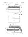
- FIG. 1is a schematic cross-section of a first self-aligned double gate field effect transistor according to the present invention.
- FIG. 2is a schematic illustration of the masks which may be used to make the self-aligned double gate field effect transistor shown in FIG. 1.
- FIGS. 3A-3His a schematic illustration of the method steps for making self-aligned double gate field effect transistors, according to the present invention.
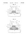
- FIG. 4is a schematic cross-section of another self-aligned single-gate field effect transistor according to the present invention.
- FIG. 5is a schematic cross-section of another self-aligned double-gate field effect transistor according to the present invention.
- support structure used hereinafteris meant to cover any kind of substrate, including semiconductor substrates, substrates comprising an insulating top layer, and the like. Such a support structure may comprise different semiconductor layers and other kind of layers. Other semiconductor devices may be integrated into the same support structure.
- a sidewallany kind of surface of a semiconductor structure is meant which is sloped with respect to the plane of the substrate. Of particular importance are sidewalls which are perpendicular with respect to said substrate's plane.
- a “raised” channelfor example, a channel is meant which is elevated with respect to the layers or support structure underneath, as opposed to a channel being integrated into the layers or support structure underneath.
- FIG. 1A cross-sectional view of a first double-gate FET 10, according to the present invention, is illustrated in FIG. 1.
- FIG. 2A schematic view of the four lithographic masks used to make the FET 10, is given in FIG. 2.
- the FET 10is situated on a substrate 11 and basically comprises a bottom gate 13, made of Tungsten for example, protected by bottom gate sidewall insulators 12. SiO 2 is well suited as insulator 12. On top of the bottom gate 13, a thin bottom gate insulator 14 is situated. In the present example this insulator 14 comprises SiO 2 . The semiconductor channel region 15 and the heavily doped source- and drain regions 20.1 and 20.2 are formed on top of the insulator 14. Between the top gate 21 and the channel region 15 another thin insulator 22, referred to as top gate insulator, is situated. The top gate 21 may comprise Tungsten, for example. On top of the top gate 21 a gate pillar 19 is formed. This gate pillar 19 may comprise silicon nitride.
- top gate sidewall insulators 18.1 and 18.2comprising SiO 2 , for example.
- Source and drain sidewall extensions 17.1 and 17.2are deposited adjacent to said top gate sidewall insulators 18.1 and 18.2 and are carried by the source and drain regions 20.1 and 20.1.
- the source and drain sidewall extensions 17.1 and 17.2are made of amorphous silicon.
- source and drain contacts 16.1 and 16.2are formed. They make contact to the respective sidewall extensions 17.1, 17.2 and the source- and drain regions 20.1, 20.2.
- Metal suicidesare well suited as source and drain contacts 16.1 and 16.2.
- Typical dimensions of the layers of the FET 10are given below.
- the thickness of the respective layers and the material according to the present embodimentare specified in parentheses:
- bottom gate insulator 14between 1 nm and 10 nm (4 nm SiO 2 );
- bottom gate 13between 5 nm and 100 nm (25 nm Tungsten);
- bottom gate sidewall insulator 12between 5 nm and 80 nm (25 nm SiO 2 );
- top gate insulator 22between 1 nm and 15 nm (2.5 nm SiO 2 );
- top gate 21between 5 nm and 100 nm (25 nm Tungsten);
- gate pillar 19thickness of a few nanometers and more (75 nm Silicon Nitride);
- the FET's structureis highly symmetrical and that the top gate 21 is precisely aligned to the bottom gate 13.
- the lateral extension of the bottom gate 13 together with the bottom gate sidewall insulators 12is approximately the same as the lateral extension of the channel 15 together with the drain region 20.1 and source region 20.2.
- FIG. 2A schematic view of the four lithographic masks M1-M4, used to make the FET 10, is given in FIG. 2.
- the first mask M1is used to define the bottom gate 13.
- the second mask M2defines the size and shape of the top gate 21.
- the third mask M3is employed to define the sidewall area 16.1, 16.2, 17.1, 17.2, 18.1 and 18.2.
- the last mask M4may be used to define source and drain interconnects (not shown in FIG. 1).
- FIGS. 3A through 3HA method according to the present invention is now described in connection with a sequence of FIGS. 3A through 3H.
- the device 47(second embodiment) is slightly different from the first embodiment.
- the main distinguishing featureis the substrate which comprises a handle wafer 34 and an insulating layer 35.
- the second embodimentis an SOI implementation of the present invention.
- a bonding techniquemay be used.
- an epitaxial silicon layer 31is grown on a silicon wafer 9.
- This epitaxial silicon layer 31may comprise an etch stop layer, or a cleavage layer 8 may be provided between the epitaxial silicon layer 31 and the substrate 9, as illustrated in FIG. 3A.
- the silicon layer 31is then oxidized to produce a bottom gate oxide 32.
- the thickness of the bottom gate oxide 32depends on different parameters such as the duration of oxidization, for example.
- a bottom gate layer 33is formed.
- the bottom gate layer 33can be formed by means of deposition, for example. Now, this structure 31, 32, 33 is flipped over and attached to an oxide 35 covered handle silicon wafer 34, as shown in FIG. 3B.
- the structure 31, 32, 33can for example be bonded to the oxide 35 of the handle silicon wafer 34. Subsequently, the original silicon wafer 9 containing layer 31 is etched back leaving a structure with the unpatterned layer sequence 31, 32, 33, 35, 34 on top. Likewise, the silicon wafer 9 may be removed by cleaving along layer 8. If the epitaxial silicon layer 31 comprises an etch stop layer, this epitaxial silicon layer 31 is etched back down to this etch stop layer. Since there are different ways to obtain such an unpatterned layer sequence, no illustration is given.
- the starting layers (layers 31, 32, 33, see FIG. 3A)are unpersonalized.
- the bottom gateis not structured (patterned) prior to the fabrication of the channel layer 15. This is very important since it permits the built up of an inventory of starting wafers (partially processed wafers) and the attainment of a high degree of perfection for these wafers.
- the layers 31-33are partially patterned using a mask similar to the mask M1 in FIG. 2. Then, silicon dioxide sidewalls 36 are formed and the uppermost portion of the channel layer 31 is oxidized to from layer 37. Instead of oxidizing the channel layer 31, one may likewise form an oxide layer 37 on top of layer 31 (As illustrated in FIG. 3C).
- a top gate layer 38is now deposited on top of the oxide layer 37. Please note that this top gate layer 38 may overlap the layers underneath, because the sidewall 36 permits the top gate 38 to cross over the bottom gate 33 without causing a short circuit.
- a mask similar to mask M2(see FIG. 2) is now used to partially pattern the top gate 38, oxide layer 37, and channel layer 31 using the bottom gate oxide 32 as the etch stop. At this stage of the inventive method, the channel area remaining is formed by the overlap of the two masks M1 and M2.
- a thick insulator 39is now deposited followed by an anisotropical etch step using a mask similar to mask M3 of FIG. 2. This etch step stops on the top gate 38, or after etching through the exposed area of the bottom gate insulator 32 (see FIG. 3C) stopping on the exposed area of the bottom gate 33.
- layer 38is etched, stopping on the top gate insulator 37, and the exposed area of the bottom gate 33 is etched stopping on the handle insulator 35.
- the exposed channel layer 31may now be implanted with an appropriate source/drain implant in order to form the source and drain regions 41.1 and 41.2 shown in FIG. 3D.
- the source and drain regions 41.1, 41.2are in the same plane as the channel 31 and are in direct contact with this channel 31 because they are formed in the channel layer by introduction of dopants.
- the shape of the bottom gate 33is given by M1-(M3 AND NOT M2).
- the final shape of the top gate 38is defined by M2 AND NOT M3, as shown in FIG. 2.
- next step addressed in the followingis supported by the illustration in FIG. 3E.
- a silicon dioxide layeris deposited and etched back anisotropically to form the sidewalls 40 adjacent to the top gate 38, gate pillar 39, bottom gate 33, bottom gate insulator 32, and channel 31.
- a layer of amorphous siliconis deposited and etched back to form sidewalls 45.
- the etchingis continued to remove the exposed horizontal channel regions 41.1 and 41.2 later serving as gate and source, such that part of the bottom gate oxide 32 becomes exposed.
- the amorphous silicon just depositedis now ion implanted with the appropriate doping.
- Well suited as dopantsare boron, phosphorous, and arsenic, for example.
- the structureis now annealed resulting in the rapid redistribution of the dopant throughout the amorphous silicon layer, the crystallization of the amorphous silicon to form a region of high conductivity, and driving in of the dopant to augment the doping in the source/drain regions 41.1, 41.2.
- the remaining channel area(including the source and drain regions) is now defined by M1 AND M2 AND (M3+sidewall 40 & 45).
- the structure formed thus far(31, 41.1, 41.2, 37, 38, 39, 40, 45), is now used as etch mask to etch through the bottom gate insulator 32. and the bottom gate 33.
- the etchis changed to an isotropic etch to undercut the bottom gate insulator 32 and recess the bottom gate 33.
- a conformal insulatoris then deposited to fill the recess.
- This conformal insulatoris now etched back with an anisotropic etch, to leave the insulator 46 in the recessed enclaves underneath the bottom gate insulator 32 and adjacent to the bottom gate 33.
- silicide sidewall layers 43are formed. This can be done by siliciding the exposed silicon 45 using a standard self-aligned Silicide (SALICIDE) process, for example.
- SALICIDEself-aligned Silicide
- This SALICIDE processis a process where a metal layer is deposited and reacted with with the exposed silicon to form a silicide. Then the unreacted metal is etched off, leaving the silicided regions 43. As illustrated in FIG. 3H, these silicided regions 43 make an electrical connection to the source/drain regions 41.1 and 41.2.
- a thick conformal metal layer 44may then be deposited and structured to fill the ⁇ grooves ⁇ adjacent to the transistor formed. This metal layer 44 may be etched using a mask M4, for example. One may also polish the upper surface of the structure to remove the metal layer 44 from the gate pillar 39, using a chemical-mechanical polish. It is important that the metal layer 44 does not serve as short circuit for source 41.1 and drain 41.2.
- FETsare formed next to each other, these devices may share either the source or drain contact.
- the outer sidewall shown at the margin of FIG. 3Hmay serve as gate of an adjacent FET.
- FIG. 4Another implementation of the present invention is illustrated in FIG. 4.
- a single gate field effect transistor 50is shown. It comprises a single crystal channel 55 being confined between a support structure 51 on one side and a top gate insulator 52 and top gate 53 on the opposite side.
- Source and drain regions 50.1, 50.2are an integral part of the channel 55. They are formed in said channel 55 by introduction of suited dopants.
- a conducting top gate pillar 59is formed on top of said top gate 53.
- Top gate sidewall insulators 58.1 and 58.2cover at least part of the sidewalls of said top gate pillar 59 and top gate 53.
- Source and drain sidewall extensions 57.1, 57.2are situated on said source and drain regions 50.1, 50.1 and adjacent to said top gate sidewall insulators 58.1 and 58.2.
- the field effect transistor 50may further comprise silicided portions 56.1, 56.2, serving as source and drain contacts and covering part of said source and drain sidewall extensions 57.1, 57.2 and source and drain regions 50.1, 50.2. These silicided portions 56.1, 56.2 can be omitted.
- the lateral extension of said top gate 53, top gate pillar 59, top gate sidewall insulators 58.1, 58.2, and source and drain sidewall extensions 57.1, 57.2together approximately define the lateral extension of said channel 55 and source and drain regions 50.1, 50.2 being formed in said channel 55.
- FIG. 5Another field effect transistor 60, according to the present invention, is illustrated in FIG. 5. It comprises a support structure 61 on top of which the following layers are formed:
- channel 65with integrated source and drain regions 60.1, 60.2,
- the field effect transistor 60 of FIG. 5further comprises optional silicided portions 66.1 and 66.2.
- the bottom gate 73is self-aligned with respect to the top gate 63.
- Layer 21, 38, 53, or 63may be silicided polysilicon.
- This silicided polysiliconmay be deposited as a silicide/amorphous silicon sandwich, and doped n-type or p-type for a n-channel or p-channel FET, respectively. This would provide a lower threshold voltage than the gates described in connection with FIGS. 1 and 3A-3H, for example.
- the channel layer 15, 33, 55, or 65may be etched using the silicon dioxide sidewall 18.1, 18.2, 40, 58.1, 58.2, or 68.1, 68.2 as a mask prior to the amorphous silicon deposition leading to the formation of layers 17.1, 17.2, 45, 57.1, 57.2, or 67.1, 67.2.
- Thishas the advantage of a shorter etching time for the amorphous silicon and a closer proximity of the heavily doped amorphous silicon to the channel 15, 31, 55 or 65.
- the disadvantageis that the vertical interface between the amorphous and single crystal silicon may be harder to clean.
- the amorphous silicon 17.1, 17.2, 45, 57.1, 57.2, or 67.1, 67.2may be doped in-situ, or it may be doped from a diffusion source.
- the doped regions 20.1, 20.2, 41.1, 41.2, 50.1, 50.2, or 60.1, 60.2may be doped by diffusion from the amorphous silicon layers 17.1, 17.2, 45, 57.1, 57.2, or 67.1 and 67.2.
- An additional silicon dioxide layer(not shown) may be deposited after the silicide formation and before depositing the source/drain interconnects 44. This additional layer may be etched back to leave a thicker insulator separating the bottom gate from the source/drain interconnect metal 44.
- the bottom gate 13, 33, or 73may be etched after the silicide formation.
- Mask M4may be omitted and the polishing continued until the metal layer 44 is removed from the field area (regions coated by the nitride 39 outside the device area).
- the interconnect metal 44may be removed from over the gate using an aligned mask (M4 with an opening above the gate). This is possible since the lateral extent of the sidewall, as shown in FIG. 1, is greater than an alignment tolerance.
- the interconnect layer 44may be omitted entirely (as illustrated in FIG. 1), allowing the silicide contacts 16.1 and 16.2 to be contacted directly with back-end-of-the-line vias.
- the mask M4may be omitted and the polishing continued until the metal layer 44 is removed from the field area (regions coated by the nitride 39 outside the device area). This will leave layer 44 over the source and drain contacts, filling the donut, to allow easy contact by back-end-of-the-line vias.
- the bottom gate 73 in FIG. 5may also be etched back, in order to provide room for insulators similar to the insulators 46 in FIG. 3H.
- the FET 50may be made on top of an insulating layer (not shown in FIG. 4) in order to electrically isolate it from the support structure 51.
- the present FETscan be made on different kind of support structures.
- Typical support structuresare silicon-on-insulator (SOI) substrates and conventional semiconductor substrates, just to give two examples.
- SOIsilicon-on-insulator
- the sidewall source/drain together with the top gate, the gate pillar and the top gate sidewall insulatorsserve as a mask structure.
- This mask structureserves as an etch mask to at least etch through the layer which later serves as channel with integrated source/drain regions (see FIG. 4, for example).
- This etch maskmay also be used to etch through the bottom gate insulator and the bottom gate (see FIG. 1, for example). I.e., the lateral extension of the channel 15 (31 in FIG. 3H) source/drain regions 20.1 and 20.2. (41.1 and 41.2 in FIG. 3H), the bottom gate insulator 14 (32 in FIG. 3H) and the bottom gate 13 (33 in FIG.
- 3His defined by the lateral extension of this mask structure. It is another important feature that self-aligned silicide source and drain contacts 16.1, 16.2 (43 in FIGS. 3G-3H) are formed in a subsequent step. The way these steps are carried through, allows to make a structure where the bottom gate, source/drain contacts, source/drain extensions, the source region and the drain region are all automatically aligned (referred to as self-alignment) to the top gate.
- An additional degree of self-alignmentcan be achieved by aligning the source and drain interconnects to the gate pillar by means of a planarization step.
- a modification of the present double gate FETis a structure where the bottom gate has a thicker oxide, and hence less control than the top gate. This structure still retains most of the scaling advantages of the symmetrical structure presented herein.
- the bottom gate, for the modified deviceis used mainly for the purpose of threshold voltage control in order to manage the speed or standby current when in active or standby modes. Such power management techniques are getting more and more important in todays computer environment.
- the double gate FET with thicker bottom gate oxidecan be made using any of the inventive methods described above.
- the inventionis described for single FETs (n- or p-channel). For a complementary technology, at least two additional masks are needed to mask out the selective p- and n-implants.
- the inventive processcan be used to make any kind of discrete semiconductor devices, as well as integrated devices such as very large scale integrated (VLSI) and ultra large scale integrated (ULSI) devices, for example.
- VLSIvery large scale integrated
- ULSIultra large scale integrated
- the inventive methodis well suited for making random access memories (RAMs), read only memories (ROMs), erasable programmable read only memories (EPROMs), electrically erasable programmable read only memories (EEPROMs), and programmable logic arrays (PLAs)
Landscapes
- Engineering & Computer Science (AREA)
- Physics & Mathematics (AREA)
- Condensed Matter Physics & Semiconductors (AREA)
- General Physics & Mathematics (AREA)
- Manufacturing & Machinery (AREA)
- Computer Hardware Design (AREA)
- Microelectronics & Electronic Packaging (AREA)
- Power Engineering (AREA)
- Thin Film Transistor (AREA)
Abstract
Description
Claims (10)
Priority Applications (5)
| Application Number | Priority Date | Filing Date | Title |
|---|---|---|---|
| US08/767,916US5773331A (en) | 1996-12-17 | 1996-12-17 | Method for making single and double gate field effect transistors with sidewall source-drain contacts |
| KR1019970049136AKR100288667B1 (en) | 1996-12-17 | 1997-09-26 | Method for making single and double gate field effect transistors with sidewall source-drain contacts |
| JP28834797AJP3282143B2 (en) | 1996-12-17 | 1997-10-21 | Single gate and double gate field effect transistors and fabrication method |
| TW086115908ATW372357B (en) | 1996-12-17 | 1997-10-28 | Single and double gate field effect transistors with sidewall source-drain contacts |
| SG1997004059ASG66410A1 (en) | 1996-12-17 | 1997-11-14 | Single and double gate field effect transistors with sidewall source-drain contacts |
Applications Claiming Priority (1)
| Application Number | Priority Date | Filing Date | Title |
|---|---|---|---|
| US08/767,916US5773331A (en) | 1996-12-17 | 1996-12-17 | Method for making single and double gate field effect transistors with sidewall source-drain contacts |
Publications (1)
| Publication Number | Publication Date |
|---|---|
| US5773331Atrue US5773331A (en) | 1998-06-30 |
Family
ID=25080961
Family Applications (1)
| Application Number | Title | Priority Date | Filing Date |
|---|---|---|---|
| US08/767,916Expired - LifetimeUS5773331A (en) | 1996-12-17 | 1996-12-17 | Method for making single and double gate field effect transistors with sidewall source-drain contacts |
Country Status (5)
| Country | Link |
|---|---|
| US (1) | US5773331A (en) |
| JP (1) | JP3282143B2 (en) |
| KR (1) | KR100288667B1 (en) |
| SG (1) | SG66410A1 (en) |
| TW (1) | TW372357B (en) |
Cited By (79)
| Publication number | Priority date | Publication date | Assignee | Title |
|---|---|---|---|---|
| US5994177A (en)* | 1999-02-05 | 1999-11-30 | Taiwan Semiconductor Manufacturing Company, Ltd. | Dynamic threshold MOSFET using accumulated base BJT level shifter for low voltage sub-quarter micron transistor |
| EP0993032A3 (en)* | 1998-10-06 | 2000-05-31 | Sel Semiconductor Energy Laboratory Co., Ltd. | Apparatus having integrated circuits made of TFT devices, and methods of manufacture thereof |
| US6174756B1 (en)* | 1997-09-30 | 2001-01-16 | Siemens Aktiengesellschaft | Spacers to block deep junction implants and silicide formation in integrated circuits |
| FR2799307A1 (en)* | 1999-10-01 | 2001-04-06 | France Telecom | Semiconductor device, especially MOSFET of silicon-on-nothing architecture, has source and drain regions covering opposite silicon thin film end zones extending beyond overlying gate dielectric layer |
| WO2001057930A1 (en)* | 2000-02-02 | 2001-08-09 | Hitachi, Ltd. | Semiconductor device and its manufacturing method |
| US6413802B1 (en) | 2000-10-23 | 2002-07-02 | The Regents Of The University Of California | Finfet transistor structures having a double gate channel extending vertically from a substrate and methods of manufacture |
| US20020086465A1 (en)* | 2000-12-31 | 2002-07-04 | Houston Theodore W. | Sub-lithographics opening for back contact or back gate |
| US6426532B1 (en)* | 1998-06-30 | 2002-07-30 | Sharp Kabushiki Kaisha | Semiconductor device and method of manufacture thereof |
| US6437377B1 (en)* | 2001-01-24 | 2002-08-20 | International Business Machines Corporation | Low dielectric constant sidewall spacer using notch gate process |
| US6445050B1 (en) | 2000-02-08 | 2002-09-03 | International Business Machines Corporation | Symmetric device with contacts self aligned to gate |
| US20020140039A1 (en)* | 2000-11-13 | 2002-10-03 | International Business Machines Corporation | Double gate trench transistor |
| US20020153587A1 (en)* | 2000-03-16 | 2002-10-24 | International Business Machines Corporation | Double planar gated SOI MOSFET structure |
| US6479332B2 (en)* | 1993-05-12 | 2002-11-12 | Micron Technology, Inc. | Methods of forming integrated circuitry |
| US6503833B1 (en) | 2000-11-15 | 2003-01-07 | International Business Machines Corporation | Self-aligned silicide (salicide) process for strained silicon MOSFET ON SiGe and structure formed thereby |
| US6521940B1 (en) | 1990-12-31 | 2003-02-18 | Kopin Corporation | High density electronic circuit modules |
| FR2829294A1 (en)* | 2001-09-03 | 2003-03-07 | Commissariat Energie Atomique | HORIZONTAL SELF-ALIGNED GRID FIELD EFFECT TRANSISTOR AND METHOD OF MANUFACTURING SUCH A TRANSISTOR |
| US6555880B2 (en) | 2001-06-07 | 2003-04-29 | International Business Machines Corporation | Self-aligned silicide process utilizing ion implants for reduced silicon consumption and control of the silicide formation temperature and structure formed thereby |
| US6562665B1 (en)* | 2000-10-16 | 2003-05-13 | Advanced Micro Devices, Inc. | Fabrication of a field effect transistor with a recess in a semiconductor pillar in SOI technology |
| US6580132B1 (en) | 2002-04-10 | 2003-06-17 | International Business Machines Corporation | Damascene double-gate FET |
| US6610576B2 (en)* | 2001-12-13 | 2003-08-26 | International Business Machines Corporation | Method for forming asymmetric dual gate transistor |
| US6627518B1 (en)* | 1998-02-27 | 2003-09-30 | Seiko Epson Corporation | Method for making three-dimensional device |
| US6627953B1 (en)* | 1990-12-31 | 2003-09-30 | Kopin Corporation | High density electronic circuit modules |
| US6642115B1 (en)* | 2000-05-15 | 2003-11-04 | International Business Machines Corporation | Double-gate FET with planarized surfaces and self-aligned silicides |
| US6646307B1 (en) | 2002-02-21 | 2003-11-11 | Advanced Micro Devices, Inc. | MOSFET having a double gate |
| US6645861B2 (en) | 2001-04-18 | 2003-11-11 | International Business Machines Corporation | Self-aligned silicide process for silicon sidewall source and drain contacts |
| US20040119115A1 (en)* | 2002-12-23 | 2004-06-24 | Chan Kevin K. | Nitride-encapsulated FET (NNCFET) |
| DE10260334A1 (en)* | 2002-12-20 | 2004-07-15 | Infineon Technologies Ag | Fin field effect transistor memory cell, fin field effect transistor memory cell arrangement and method for producing a fin field effect transistor memory cell |
| US20040197970A1 (en)* | 2001-02-07 | 2004-10-07 | Hiroshi Komatsu | Semiconductor device and method of manufacturing thereof |
| US20040256693A1 (en)* | 2003-05-07 | 2004-12-23 | Tsutomu Sato | Semiconductor device and method of manufacturing the same |
| US20040262688A1 (en)* | 2003-06-25 | 2004-12-30 | International Business Machines Corporation | METHOD OF MAKING A finFET HAVING SUPPRESSED PARASITIC DEVICE CHARACTERISTICS |
| US20050003612A1 (en)* | 2003-07-03 | 2005-01-06 | Hackler Douglas R. | Sram cell |
| US20050001319A1 (en)* | 2003-07-03 | 2005-01-06 | Hackler Douglas R. | Multi-configurable independently multi-gated MOSFET |
| US20050003592A1 (en)* | 2003-06-18 | 2005-01-06 | Jones A. Brooke | All-around MOSFET gate and methods of manufacture thereof |
| US20050037582A1 (en)* | 2003-08-13 | 2005-02-17 | International Business Machines Corporation | Device threshold control of front-gate silicon-on-insulator mosfet using a self-aligned back-gate |
| US20050059252A1 (en)* | 2003-09-15 | 2005-03-17 | International Business Machines Corporation | Self-aligned planar double-gate process by self-aligned oxidation |
| US20050266692A1 (en)* | 2004-06-01 | 2005-12-01 | Brask Justin K | Method of patterning a film |
| US20050282318A1 (en)* | 2004-06-18 | 2005-12-22 | Dao Thuy B | Method of forming a transistor with a bottom gate |
| US6987050B2 (en) | 2000-05-11 | 2006-01-17 | International Business Machines Corporation | Self-aligned silicide (salicide) process for low resistivity contacts to thin film silicon-on-insulator and bulk MOSFETS and for shallow junctions |
| US20060022264A1 (en)* | 2004-07-30 | 2006-02-02 | Leo Mathew | Method of making a double gate semiconductor device with self-aligned gates and structure thereof |
| US7019342B2 (en) | 2003-07-03 | 2006-03-28 | American Semiconductor, Inc. | Double-gated transistor circuit |
| US20060086977A1 (en)* | 2004-10-25 | 2006-04-27 | Uday Shah | Nonplanar device with thinned lower body portion and method of fabrication |
| US20060172496A1 (en)* | 2005-01-28 | 2006-08-03 | International Business Machines Corporation | DOUBLE-GATE FETs (FIELD EFFECT TRANSISTORS) |
| US20060172468A1 (en)* | 2005-01-31 | 2006-08-03 | Orlowski Marius K | Method of making a planar double-gated transistor |
| US20060186484A1 (en)* | 2005-02-23 | 2006-08-24 | Chau Robert S | Field effect transistor with narrow bandgap source and drain regions and method of fabrication |
| US20060261411A1 (en)* | 2003-06-27 | 2006-11-23 | Hareland Scott A | Nonplanar device with stress incorporation layer and method of fabrication |
| US20070026617A1 (en)* | 2000-10-18 | 2007-02-01 | Adkisson James W | Method of fabricating semiconductor side wall fin |
| US20070023817A1 (en)* | 2005-07-28 | 2007-02-01 | Dao Thuy B | Structure and manufacturing method of multi-gate dielectric thicknesses for planar double gate device having multi-threshold voltages |
| US20070102761A1 (en)* | 2005-11-09 | 2007-05-10 | Kabushiki Kaisha Toshiba | Semiconductor device and method of fabricating the same |
| US20070152266A1 (en)* | 2005-12-29 | 2007-07-05 | Intel Corporation | Method and structure for reducing the external resistance of a three-dimensional transistor through use of epitaxial layers |
| US20070152272A1 (en)* | 2005-12-29 | 2007-07-05 | Jeong Ho Park | Method for fabricating a transistor using a soi wafer |
| US20070178649A1 (en)* | 2006-01-27 | 2007-08-02 | Swift Craig T | Double-gated non-volatile memory and methods for forming thereof |
| US7259049B2 (en) | 2002-12-23 | 2007-08-21 | International Business Machines Corporation | Self-aligned isolation double-gate FET |
| US20080164528A1 (en)* | 2007-01-10 | 2008-07-10 | International Business Machines Corporation | Self-aligned metal-semiconductor alloy and metallization for sub-lithographic source and drain contacts |
| US20080194069A1 (en)* | 2004-09-02 | 2008-08-14 | Koninklijke Philips Electronics N.V. | Method of Manufacturing a Semiconductor Device and Semiconductor Device Obtained With Such a Method |
| US20080213973A1 (en)* | 2005-06-07 | 2008-09-04 | Freescale Semiconductor, Inc. | Method of fabricating a substrate for a planar, double-gated, transistor process |
| US20080220569A1 (en)* | 2007-03-09 | 2008-09-11 | Commissariat A L'energie Atomique | Method for manufacturing a field effect transistor with auto-aligned grids |
| US20090061572A1 (en)* | 2003-06-27 | 2009-03-05 | Intel Corporation | Nonplanar semiconductor device with partially or fully wrapped around gate electrode and methods of fabrication |
| US20090298275A1 (en)* | 2007-09-10 | 2009-12-03 | International Business Machines Corporation | Metal High-K Transistor Having Silicon Sidewall For Reduced Parasitic Capacitance, And Process To Fabricate Same |
| US7652330B1 (en) | 2003-07-03 | 2010-01-26 | American Semiconductor, Inc. | Independently-double-gated combinational logic |
| US7679125B2 (en) | 2005-12-14 | 2010-03-16 | Freescale Semiconductor, Inc. | Back-gated semiconductor device with a storage layer and methods for forming thereof |
| US7736956B2 (en) | 2005-08-17 | 2010-06-15 | Intel Corporation | Lateral undercut of metal gate in SOI device |
| US7781771B2 (en) | 2004-03-31 | 2010-08-24 | Intel Corporation | Bulk non-planar transistor having strained enhanced mobility and methods of fabrication |
| US20100327376A1 (en)* | 2007-09-10 | 2010-12-30 | International Business Machines Corporation | Metal High-K Transistor Having Silicon Sidewall For Reduced Parasitic Capacitance, And Process To Fabricate Same |
| US7879675B2 (en) | 2005-03-14 | 2011-02-01 | Intel Corporation | Field effect transistor with metal source/drain regions |
| US7898041B2 (en) | 2005-06-30 | 2011-03-01 | Intel Corporation | Block contact architectures for nanoscale channel transistors |
| US7902014B2 (en) | 2005-09-28 | 2011-03-08 | Intel Corporation | CMOS devices with a single work function gate electrode and method of fabrication |
| US7960794B2 (en) | 2004-08-10 | 2011-06-14 | Intel Corporation | Non-planar pMOS structure with a strained channel region and an integrated strained CMOS flow |
| US7989280B2 (en) | 2005-11-30 | 2011-08-02 | Intel Corporation | Dielectric interface for group III-V semiconductor device |
| US8071983B2 (en) | 2005-06-21 | 2011-12-06 | Intel Corporation | Semiconductor device structures and methods of forming semiconductor structures |
| US8084818B2 (en) | 2004-06-30 | 2011-12-27 | Intel Corporation | High mobility tri-gate devices and methods of fabrication |
| US8193567B2 (en) | 2005-09-28 | 2012-06-05 | Intel Corporation | Process for integrating planar and non-planar CMOS transistors on a bulk substrate and article made thereby |
| US20120149157A1 (en)* | 2007-10-23 | 2012-06-14 | Semiconductor Energy Laboratory Co., Ltd. | Semiconductor device and method for manufacturing semiconductor device |
| US8268709B2 (en) | 2004-09-29 | 2012-09-18 | Intel Corporation | Independently accessed double-gate and tri-gate transistors in same process flow |
| US8362566B2 (en) | 2008-06-23 | 2013-01-29 | Intel Corporation | Stress in trigate devices using complimentary gate fill materials |
| US8617945B2 (en) | 2006-08-02 | 2013-12-31 | Intel Corporation | Stacking fault and twin blocking barrier for integrating III-V on Si |
| US9203041B2 (en) | 2014-01-31 | 2015-12-01 | International Business Machines Corporation | Carbon nanotube transistor having extended contacts |
| US9337307B2 (en) | 2005-06-15 | 2016-05-10 | Intel Corporation | Method for fabricating transistor with thinned channel |
| CN111670486A (en)* | 2018-01-29 | 2020-09-15 | 麻省理工学院 | Back-gate field effect transistor and method of making the same |
| US12015088B2 (en)* | 2019-11-20 | 2024-06-18 | Samsung Display Co., Ltd. | Display device and method of fabricating the same |
Families Citing this family (4)
| Publication number | Priority date | Publication date | Assignee | Title |
|---|---|---|---|---|
| TW490745B (en)* | 2000-05-15 | 2002-06-11 | Ibm | Self-aligned double gate MOSFET with separate gates |
| JP4943576B2 (en)* | 2000-10-19 | 2012-05-30 | 白土 猛英 | MIS field effect transistor and manufacturing method thereof |
| US6781409B2 (en)* | 2001-10-10 | 2004-08-24 | Altera Corporation | Apparatus and methods for silicon-on-insulator transistors in programmable logic devices |
| US12040409B2 (en)* | 2021-02-09 | 2024-07-16 | Taiwan Semiconductor Manufacturing Company Limited | Thin film transistor including a dielectric diffusion barrier and methods for forming the same |
Citations (14)
| Publication number | Priority date | Publication date | Assignee | Title |
|---|---|---|---|---|
| US4714685A (en)* | 1986-12-08 | 1987-12-22 | General Motors Corporation | Method of fabricating self-aligned silicon-on-insulator like devices |
| US4797718A (en)* | 1986-12-08 | 1989-01-10 | Delco Electronics Corporation | Self-aligned silicon MOS device |
| US5019525A (en)* | 1987-08-18 | 1991-05-28 | Texas Instruments Incorporated | Method for forming a horizontal self-aligned transistor |
| US5027177A (en)* | 1989-07-24 | 1991-06-25 | Hughes Aircraft Company | Floating base lateral bipolar phototransistor with field effect gate voltage control |
| US5166084A (en)* | 1991-09-03 | 1992-11-24 | Motorola, Inc. | Process for fabricating a silicon on insulator field effect transistor |
| US5262655A (en)* | 1991-04-23 | 1993-11-16 | Mitsubishi Denki Kabushiki Kaisha | Thin film field effect device having an LDD structure and a method of manufacturing such a device |
| US5273921A (en)* | 1991-12-27 | 1993-12-28 | Purdue Research Foundation | Methods for fabricating a dual-gated semiconductor-on-insulator field effect transistor |
| US5289027A (en)* | 1988-12-09 | 1994-02-22 | Hughes Aircraft Company | Ultrathin submicron MOSFET with intrinsic channel |
| US5346839A (en)* | 1991-06-10 | 1994-09-13 | Texas Instruments Incorporated | Sidewall doping technique for SOI transistors |
| US5348899A (en)* | 1993-05-12 | 1994-09-20 | Micron Semiconductor, Inc. | Method of fabricating a bottom and top gated thin film transistor |
| US5376561A (en)* | 1990-12-31 | 1994-12-27 | Kopin Corporation | High density electronic circuit modules |
| US5420048A (en)* | 1991-01-09 | 1995-05-30 | Canon Kabushiki Kaisha | Manufacturing method for SOI-type thin film transistor |
| US5461250A (en)* | 1992-08-10 | 1995-10-24 | International Business Machines Corporation | SiGe thin film or SOI MOSFET and method for making the same |
| DE19524027A1 (en)* | 1994-06-30 | 1996-01-04 | Toshiba Kawasaki Kk | Semiconductor device |
Family Cites Families (1)
| Publication number | Priority date | Publication date | Assignee | Title |
|---|---|---|---|---|
| JPH08162640A (en)* | 1994-11-30 | 1996-06-21 | Sony Corp | Manufacture of semiconductor device |
- 1996
- 1996-12-17USUS08/767,916patent/US5773331A/ennot_activeExpired - Lifetime
- 1997
- 1997-09-26KRKR1019970049136Apatent/KR100288667B1/ennot_activeExpired - Fee Related
- 1997-10-21JPJP28834797Apatent/JP3282143B2/ennot_activeExpired - Fee Related
- 1997-10-28TWTW086115908Apatent/TW372357B/ennot_activeIP Right Cessation
- 1997-11-14SGSG1997004059Apatent/SG66410A1/enunknown
Patent Citations (14)
| Publication number | Priority date | Publication date | Assignee | Title |
|---|---|---|---|---|
| US4797718A (en)* | 1986-12-08 | 1989-01-10 | Delco Electronics Corporation | Self-aligned silicon MOS device |
| US4714685A (en)* | 1986-12-08 | 1987-12-22 | General Motors Corporation | Method of fabricating self-aligned silicon-on-insulator like devices |
| US5019525A (en)* | 1987-08-18 | 1991-05-28 | Texas Instruments Incorporated | Method for forming a horizontal self-aligned transistor |
| US5289027A (en)* | 1988-12-09 | 1994-02-22 | Hughes Aircraft Company | Ultrathin submicron MOSFET with intrinsic channel |
| US5027177A (en)* | 1989-07-24 | 1991-06-25 | Hughes Aircraft Company | Floating base lateral bipolar phototransistor with field effect gate voltage control |
| US5376561A (en)* | 1990-12-31 | 1994-12-27 | Kopin Corporation | High density electronic circuit modules |
| US5420048A (en)* | 1991-01-09 | 1995-05-30 | Canon Kabushiki Kaisha | Manufacturing method for SOI-type thin film transistor |
| US5262655A (en)* | 1991-04-23 | 1993-11-16 | Mitsubishi Denki Kabushiki Kaisha | Thin film field effect device having an LDD structure and a method of manufacturing such a device |
| US5346839A (en)* | 1991-06-10 | 1994-09-13 | Texas Instruments Incorporated | Sidewall doping technique for SOI transistors |
| US5166084A (en)* | 1991-09-03 | 1992-11-24 | Motorola, Inc. | Process for fabricating a silicon on insulator field effect transistor |
| US5273921A (en)* | 1991-12-27 | 1993-12-28 | Purdue Research Foundation | Methods for fabricating a dual-gated semiconductor-on-insulator field effect transistor |
| US5461250A (en)* | 1992-08-10 | 1995-10-24 | International Business Machines Corporation | SiGe thin film or SOI MOSFET and method for making the same |
| US5348899A (en)* | 1993-05-12 | 1994-09-20 | Micron Semiconductor, Inc. | Method of fabricating a bottom and top gated thin film transistor |
| DE19524027A1 (en)* | 1994-06-30 | 1996-01-04 | Toshiba Kawasaki Kk | Semiconductor device |
Cited By (190)
| Publication number | Priority date | Publication date | Assignee | Title |
|---|---|---|---|---|
| US6521940B1 (en) | 1990-12-31 | 2003-02-18 | Kopin Corporation | High density electronic circuit modules |
| US6627953B1 (en)* | 1990-12-31 | 2003-09-30 | Kopin Corporation | High density electronic circuit modules |
| US6759285B2 (en) | 1993-05-12 | 2004-07-06 | Micron Technology, Inc. | Methods of forming transistors |
| US6479332B2 (en)* | 1993-05-12 | 2002-11-12 | Micron Technology, Inc. | Methods of forming integrated circuitry |
| US6689649B2 (en) | 1993-05-12 | 2004-02-10 | Micron Technology, Inc. | Methods of forming transistors |
| US20050145850A1 (en)* | 1993-05-12 | 2005-07-07 | Dennison Charles H. | Electrical interconnection and thin film transistor fabrication methods, and integrated circuitry |
| US6174756B1 (en)* | 1997-09-30 | 2001-01-16 | Siemens Aktiengesellschaft | Spacers to block deep junction implants and silicide formation in integrated circuits |
| US6627518B1 (en)* | 1998-02-27 | 2003-09-30 | Seiko Epson Corporation | Method for making three-dimensional device |
| US6682966B2 (en)* | 1998-06-30 | 2004-01-27 | Sharp Kabushiki Kaisha | Semiconductor device and method for producing the same |
| US6426532B1 (en)* | 1998-06-30 | 2002-07-30 | Sharp Kabushiki Kaisha | Semiconductor device and method of manufacture thereof |
| US20020175374A1 (en)* | 1998-06-30 | 2002-11-28 | Sharp Kabushiki Kaisha | Semiconductor device and method for producing the same |
| US6656779B1 (en) | 1998-10-06 | 2003-12-02 | Semiconductor Energy Laboratory Co., Ltd. | Semiconductor apparatus having semiconductor circuits made of semiconductor devices, and method of manufacture thereof |
| US20070063199A1 (en)* | 1998-10-06 | 2007-03-22 | Kenji Kasahara | Semiconductor apparatus having semiconductor circuits made of semiconductor devices, and method of manufacture thereof |
| EP0993032A3 (en)* | 1998-10-06 | 2000-05-31 | Sel Semiconductor Energy Laboratory Co., Ltd. | Apparatus having integrated circuits made of TFT devices, and methods of manufacture thereof |
| US7138657B2 (en) | 1998-10-06 | 2006-11-21 | Semiconductor Energy Laboratory Co., Ltd. | Semiconductor device having two insulating films provided over a substrate |
| US20040094767A1 (en)* | 1998-10-06 | 2004-05-20 | Semiconductor Energy Laboratory Co., Ltd. | Semiconductor apparatus having semiconductor circuits made of semiconductor devices, and method of manufacturing thereof |
| US5994177A (en)* | 1999-02-05 | 1999-11-30 | Taiwan Semiconductor Manufacturing Company, Ltd. | Dynamic threshold MOSFET using accumulated base BJT level shifter for low voltage sub-quarter micron transistor |
| WO2001026160A1 (en)* | 1999-10-01 | 2001-04-12 | France Telecom | Semiconductor device combining the advantages of massive and soi architecture, and method for making same |
| FR2799307A1 (en)* | 1999-10-01 | 2001-04-06 | France Telecom | Semiconductor device, especially MOSFET of silicon-on-nothing architecture, has source and drain regions covering opposite silicon thin film end zones extending beyond overlying gate dielectric layer |
| WO2001057930A1 (en)* | 2000-02-02 | 2001-08-09 | Hitachi, Ltd. | Semiconductor device and its manufacturing method |
| US6445050B1 (en) | 2000-02-08 | 2002-09-03 | International Business Machines Corporation | Symmetric device with contacts self aligned to gate |
| US6946376B2 (en) | 2000-02-08 | 2005-09-20 | International Business Machines Corporation | Symmetric device with contacts self aligned to gate |
| US20020153587A1 (en)* | 2000-03-16 | 2002-10-24 | International Business Machines Corporation | Double planar gated SOI MOSFET structure |
| US6483156B1 (en)* | 2000-03-16 | 2002-11-19 | International Business Machines Corporation | Double planar gated SOI MOSFET structure |
| US6660596B2 (en)* | 2000-03-16 | 2003-12-09 | International Business Machines Corporation | Double planar gated SOI MOSFET structure |
| US6987050B2 (en) | 2000-05-11 | 2006-01-17 | International Business Machines Corporation | Self-aligned silicide (salicide) process for low resistivity contacts to thin film silicon-on-insulator and bulk MOSFETS and for shallow junctions |
| US20060043484A1 (en)* | 2000-05-11 | 2006-03-02 | International Business Machines Corporation | Self-aligned silicide (salicide) process for low resistivity contacts to thin film silicon-on-insulator and bulk mosfets and for shallow junctions |
| US20040023460A1 (en)* | 2000-05-15 | 2004-02-05 | Cohen Guy M. | Double-gate fet with planarized surfaces and self-aligned silicides |
| US6967377B2 (en) | 2000-05-15 | 2005-11-22 | International Business Machines Corporation | Double-gate fet with planarized surfaces and self-aligned silicides |
| US6642115B1 (en)* | 2000-05-15 | 2003-11-04 | International Business Machines Corporation | Double-gate FET with planarized surfaces and self-aligned silicides |
| US6562665B1 (en)* | 2000-10-16 | 2003-05-13 | Advanced Micro Devices, Inc. | Fabrication of a field effect transistor with a recess in a semiconductor pillar in SOI technology |
| US7361556B2 (en)* | 2000-10-18 | 2008-04-22 | International Business Machines Corporation | Method of fabricating semiconductor side wall fin |
| US7265417B2 (en) | 2000-10-18 | 2007-09-04 | International Business Machines Corporation | Method of fabricating semiconductor side wall fin |
| US20070026617A1 (en)* | 2000-10-18 | 2007-02-01 | Adkisson James W | Method of fabricating semiconductor side wall fin |
| US6413802B1 (en) | 2000-10-23 | 2002-07-02 | The Regents Of The University Of California | Finfet transistor structures having a double gate channel extending vertically from a substrate and methods of manufacture |
| KR100450802B1 (en)* | 2000-11-13 | 2004-10-01 | 인터내셔널 비지네스 머신즈 코포레이션 | Double gate trench transistor |
| US6472258B1 (en) | 2000-11-13 | 2002-10-29 | International Business Machines Corporation | Double gate trench transistor |
| US7112845B2 (en) | 2000-11-13 | 2006-09-26 | International Business Machines Corporation | Double gate trench transistor |
| US20020140039A1 (en)* | 2000-11-13 | 2002-10-03 | International Business Machines Corporation | Double gate trench transistor |
| US6503833B1 (en) | 2000-11-15 | 2003-01-07 | International Business Machines Corporation | Self-aligned silicide (salicide) process for strained silicon MOSFET ON SiGe and structure formed thereby |
| US6972448B2 (en)* | 2000-12-31 | 2005-12-06 | Texas Instruments Incorporated | Sub-lithographics opening for back contact or back gate |
| US20020086465A1 (en)* | 2000-12-31 | 2002-07-04 | Houston Theodore W. | Sub-lithographics opening for back contact or back gate |
| US6437377B1 (en)* | 2001-01-24 | 2002-08-20 | International Business Machines Corporation | Low dielectric constant sidewall spacer using notch gate process |
| US20040197970A1 (en)* | 2001-02-07 | 2004-10-07 | Hiroshi Komatsu | Semiconductor device and method of manufacturing thereof |
| US7253033B2 (en)* | 2001-02-07 | 2007-08-07 | Sony Corporation | Method of manufacturing a semiconductor device that includes implanting in multiple directions a high concentration region |
| US6645861B2 (en) | 2001-04-18 | 2003-11-11 | International Business Machines Corporation | Self-aligned silicide process for silicon sidewall source and drain contacts |
| US7498640B2 (en) | 2001-04-18 | 2009-03-03 | International Business Machines Corporation | Self-aligned silicide process for silicon sidewall source and drain contacts and structure formed thereby |
| US20040108598A1 (en)* | 2001-04-18 | 2004-06-10 | International Business Machines Corporation | Self-aligned silicide process for silicon sidewall source and drain contacts and structure formed thereby |
| US6555880B2 (en) | 2001-06-07 | 2003-04-29 | International Business Machines Corporation | Self-aligned silicide process utilizing ion implants for reduced silicon consumption and control of the silicide formation temperature and structure formed thereby |
| US20030132487A1 (en)* | 2001-06-07 | 2003-07-17 | International Business Machines Corporation | Self-aligned silicide process utilizing ion implants for reduced silicon consumption and control of the silicide formation temperature and structure formed thereby |
| US6716708B2 (en) | 2001-06-07 | 2004-04-06 | International Business Machines Corporation | Self-aligned silicide process utilizing ion implants for reduced silicon consumption and control of the silicide formation temperature and structure formed thereby |
| US7022562B2 (en)* | 2001-09-03 | 2006-04-04 | Commissariat A L'energie Atomique | Field-effect transistor with horizontal self-aligned gates and the production method therefor |
| WO2003021633A1 (en)* | 2001-09-03 | 2003-03-13 | Commissariat A L'energie Atomique | Field-effect transistor with horizontal self-aligned gates and the production method therefor |
| FR2829294A1 (en)* | 2001-09-03 | 2003-03-07 | Commissariat Energie Atomique | HORIZONTAL SELF-ALIGNED GRID FIELD EFFECT TRANSISTOR AND METHOD OF MANUFACTURING SUCH A TRANSISTOR |
| US20040197977A1 (en)* | 2001-09-03 | 2004-10-07 | Simon Deleonibus | Field-effect transistor with horizontal self-aligned gates and the production method therefor |
| US6610576B2 (en)* | 2001-12-13 | 2003-08-26 | International Business Machines Corporation | Method for forming asymmetric dual gate transistor |
| US6646307B1 (en) | 2002-02-21 | 2003-11-11 | Advanced Micro Devices, Inc. | MOSFET having a double gate |
| US6580132B1 (en) | 2002-04-10 | 2003-06-17 | International Business Machines Corporation | Damascene double-gate FET |
| US6762101B2 (en) | 2002-04-10 | 2004-07-13 | International Business Machines Corporation | Damascene double-gate FET |
| DE10260334A1 (en)* | 2002-12-20 | 2004-07-15 | Infineon Technologies Ag | Fin field effect transistor memory cell, fin field effect transistor memory cell arrangement and method for producing a fin field effect transistor memory cell |
| DE10260334B4 (en)* | 2002-12-20 | 2007-07-12 | Infineon Technologies Ag | Fin field effect surge memory cell, fin field effect transistor memory cell array, and method of fabricating a fin field effect transistor memory cell |
| US7442612B2 (en) | 2002-12-23 | 2008-10-28 | International Business Machines Corporation | Nitride-encapsulated FET (NNCFET) |
| US7259049B2 (en) | 2002-12-23 | 2007-08-21 | International Business Machines Corporation | Self-aligned isolation double-gate FET |
| CN100337334C (en)* | 2002-12-23 | 2007-09-12 | 国际商业机器公司 | Dual gate FET and producing method thereof |
| US20080286930A1 (en)* | 2002-12-23 | 2008-11-20 | International Business Machines Corporation | Nitride-encapsulated fet (nncfet) |
| US7648880B2 (en) | 2002-12-23 | 2010-01-19 | International Business Machines Corporation | Nitride-encapsulated FET (NNCFET) |
| CN1294657C (en)* | 2002-12-23 | 2007-01-10 | 国际商业机器公司 | Bi-grid field effect transistor and producing method thereof |
| US7078773B2 (en) | 2002-12-23 | 2006-07-18 | International Business Machines Corporation | Nitride-encapsulated FET (NNCFET) |
| US20040119115A1 (en)* | 2002-12-23 | 2004-06-24 | Chan Kevin K. | Nitride-encapsulated FET (NNCFET) |
| US20060252241A1 (en)* | 2002-12-23 | 2006-11-09 | International Business Machines Corporation | Nitride-encapsulated FET (NNCFET) |
| US7372086B2 (en)* | 2003-05-07 | 2008-05-13 | Kabushiki Kaisha Toshiba | Semiconductor device including MOSFET and isolation region for isolating the MOSFET |
| US20040256693A1 (en)* | 2003-05-07 | 2004-12-23 | Tsutomu Sato | Semiconductor device and method of manufacturing the same |
| US20050003592A1 (en)* | 2003-06-18 | 2005-01-06 | Jones A. Brooke | All-around MOSFET gate and methods of manufacture thereof |
| US20040262688A1 (en)* | 2003-06-25 | 2004-12-30 | International Business Machines Corporation | METHOD OF MAKING A finFET HAVING SUPPRESSED PARASITIC DEVICE CHARACTERISTICS |
| US7470578B2 (en) | 2003-06-25 | 2008-12-30 | International Business Machines Corporation | Method of making a finFET having suppressed parasitic device characteristics |
| US6992354B2 (en) | 2003-06-25 | 2006-01-31 | International Business Machines Corporation | FinFET having suppressed parasitic device characteristics |
| US7820513B2 (en) | 2003-06-27 | 2010-10-26 | Intel Corporation | Nonplanar semiconductor device with partially or fully wrapped around gate electrode and methods of fabrication |
| US7714397B2 (en) | 2003-06-27 | 2010-05-11 | Intel Corporation | Tri-gate transistor device with stress incorporation layer and method of fabrication |
| US20060261411A1 (en)* | 2003-06-27 | 2006-11-23 | Hareland Scott A | Nonplanar device with stress incorporation layer and method of fabrication |
| US20100200917A1 (en)* | 2003-06-27 | 2010-08-12 | Hareland Scott A | Nonplanar device with stress incorporation layer and method of fabrication |
| US20090061572A1 (en)* | 2003-06-27 | 2009-03-05 | Intel Corporation | Nonplanar semiconductor device with partially or fully wrapped around gate electrode and methods of fabrication |
| US8273626B2 (en) | 2003-06-27 | 2012-09-25 | Intel Corporationn | Nonplanar semiconductor device with partially or fully wrapped around gate electrode and methods of fabrication |
| US8405164B2 (en) | 2003-06-27 | 2013-03-26 | Intel Corporation | Tri-gate transistor device with stress incorporation layer and method of fabrication |
| US7015547B2 (en) | 2003-07-03 | 2006-03-21 | American Semiconductor, Inc. | Multi-configurable independently multi-gated MOSFET |
| US20050001319A1 (en)* | 2003-07-03 | 2005-01-06 | Hackler Douglas R. | Multi-configurable independently multi-gated MOSFET |
| US7019342B2 (en) | 2003-07-03 | 2006-03-28 | American Semiconductor, Inc. | Double-gated transistor circuit |
| US20050003612A1 (en)* | 2003-07-03 | 2005-01-06 | Hackler Douglas R. | Sram cell |
| US6919647B2 (en) | 2003-07-03 | 2005-07-19 | American Semiconductor, Inc. | SRAM cell |
| US7652330B1 (en) | 2003-07-03 | 2010-01-26 | American Semiconductor, Inc. | Independently-double-gated combinational logic |
| WO2005017976A3 (en)* | 2003-08-13 | 2005-04-28 | Ibm | Device threshold control of front-gate silicon-on-insulator mosfet using a self-aligned back-gate |
| US20050037582A1 (en)* | 2003-08-13 | 2005-02-17 | International Business Machines Corporation | Device threshold control of front-gate silicon-on-insulator mosfet using a self-aligned back-gate |
| US7018873B2 (en)* | 2003-08-13 | 2006-03-28 | International Business Machines Corporation | Method of making a device threshold control of front-gate silicon-on-insulator MOSFET using a self-aligned back-gate |
| US7960790B2 (en) | 2003-09-15 | 2011-06-14 | International Business Machines Corporation | Self-aligned planar double-gate transistor structure |
| US20050059252A1 (en)* | 2003-09-15 | 2005-03-17 | International Business Machines Corporation | Self-aligned planar double-gate process by self-aligned oxidation |
| US20080246090A1 (en)* | 2003-09-15 | 2008-10-09 | International Business Machines Corporation | Self-aligned planar double-gate transistor structure |
| US7453123B2 (en) | 2003-09-15 | 2008-11-18 | International Business Machines Corporation | Self-aligned planar double-gate transistor structure |
| US7205185B2 (en) | 2003-09-15 | 2007-04-17 | International Busniess Machines Corporation | Self-aligned planar double-gate process by self-aligned oxidation |
| US20070138556A1 (en)* | 2003-09-15 | 2007-06-21 | International Business Machines Corporation | Self-aligned planar double-gate process by self-aligned oxidation |
| US7781771B2 (en) | 2004-03-31 | 2010-08-24 | Intel Corporation | Bulk non-planar transistor having strained enhanced mobility and methods of fabrication |
| US7579280B2 (en) | 2004-06-01 | 2009-08-25 | Intel Corporation | Method of patterning a film |
| US20050266692A1 (en)* | 2004-06-01 | 2005-12-01 | Brask Justin K | Method of patterning a film |
| US20050282318A1 (en)* | 2004-06-18 | 2005-12-22 | Dao Thuy B | Method of forming a transistor with a bottom gate |
| US7141476B2 (en)* | 2004-06-18 | 2006-11-28 | Freescale Semiconductor, Inc. | Method of forming a transistor with a bottom gate |
| US8084818B2 (en) | 2004-06-30 | 2011-12-27 | Intel Corporation | High mobility tri-gate devices and methods of fabrication |
| US20060022264A1 (en)* | 2004-07-30 | 2006-02-02 | Leo Mathew | Method of making a double gate semiconductor device with self-aligned gates and structure thereof |
| US7960794B2 (en) | 2004-08-10 | 2011-06-14 | Intel Corporation | Non-planar pMOS structure with a strained channel region and an integrated strained CMOS flow |
| US7659169B2 (en) | 2004-09-02 | 2010-02-09 | Nxp B.V. | Semiconductor device and method of manufacturing thereof |
| US20080194069A1 (en)* | 2004-09-02 | 2008-08-14 | Koninklijke Philips Electronics N.V. | Method of Manufacturing a Semiconductor Device and Semiconductor Device Obtained With Such a Method |
| US8399922B2 (en) | 2004-09-29 | 2013-03-19 | Intel Corporation | Independently accessed double-gate and tri-gate transistors |
| US8268709B2 (en) | 2004-09-29 | 2012-09-18 | Intel Corporation | Independently accessed double-gate and tri-gate transistors in same process flow |
| US7550333B2 (en) | 2004-10-25 | 2009-06-23 | Intel Corporation | Nonplanar device with thinned lower body portion and method of fabrication |
| US8502351B2 (en) | 2004-10-25 | 2013-08-06 | Intel Corporation | Nonplanar device with thinned lower body portion and method of fabrication |
| US10236356B2 (en) | 2004-10-25 | 2019-03-19 | Intel Corporation | Nonplanar device with thinned lower body portion and method of fabrication |
| US8067818B2 (en) | 2004-10-25 | 2011-11-29 | Intel Corporation | Nonplanar device with thinned lower body portion and method of fabrication |
| US20060214231A1 (en)* | 2004-10-25 | 2006-09-28 | Uday Shah | Nonplanar device with thinned lower body portion and method of fabrication |
| US9741809B2 (en) | 2004-10-25 | 2017-08-22 | Intel Corporation | Nonplanar device with thinned lower body portion and method of fabrication |
| US8749026B2 (en) | 2004-10-25 | 2014-06-10 | Intel Corporation | Nonplanar device with thinned lower body portion and method of fabrication |
| US9190518B2 (en) | 2004-10-25 | 2015-11-17 | Intel Corporation | Nonplanar device with thinned lower body portion and method of fabrication |
| US20060086977A1 (en)* | 2004-10-25 | 2006-04-27 | Uday Shah | Nonplanar device with thinned lower body portion and method of fabrication |
| US7250347B2 (en) | 2005-01-28 | 2007-07-31 | International Business Machines Corporation | Double-gate FETs (Field Effect Transistors) |
| US20060172496A1 (en)* | 2005-01-28 | 2006-08-03 | International Business Machines Corporation | DOUBLE-GATE FETs (FIELD EFFECT TRANSISTORS) |
| US7202117B2 (en) | 2005-01-31 | 2007-04-10 | Freescale Semiconductor, Inc. | Method of making a planar double-gated transistor |
| US20060172468A1 (en)* | 2005-01-31 | 2006-08-03 | Orlowski Marius K | Method of making a planar double-gated transistor |
| TWI397128B (en)* | 2005-01-31 | 2013-05-21 | Freescale Semiconductor Inc | Method for making a planar double gate transistor |
| US7825481B2 (en) | 2005-02-23 | 2010-11-02 | Intel Corporation | Field effect transistor with narrow bandgap source and drain regions and method of fabrication |
| US7893506B2 (en) | 2005-02-23 | 2011-02-22 | Intel Corporation | Field effect transistor with narrow bandgap source and drain regions and method of fabrication |
| US7518196B2 (en)* | 2005-02-23 | 2009-04-14 | Intel Corporation | Field effect transistor with narrow bandgap source and drain regions and method of fabrication |
| US20090142897A1 (en)* | 2005-02-23 | 2009-06-04 | Chau Robert S | Field effect transistor with narrow bandgap source and drain regions and method of fabrication |
| US8183646B2 (en) | 2005-02-23 | 2012-05-22 | Intel Corporation | Field effect transistor with narrow bandgap source and drain regions and method of fabrication |
| US8368135B2 (en) | 2005-02-23 | 2013-02-05 | Intel Corporation | Field effect transistor with narrow bandgap source and drain regions and method of fabrication |
| US9368583B2 (en) | 2005-02-23 | 2016-06-14 | Intel Corporation | Field effect transistor with narrow bandgap source and drain regions and method of fabrication |
| US8664694B2 (en) | 2005-02-23 | 2014-03-04 | Intel Corporation | Field effect transistor with narrow bandgap source and drain regions and method of fabrication |
| US8816394B2 (en) | 2005-02-23 | 2014-08-26 | Intel Corporation | Field effect transistor with narrow bandgap source and drain regions and method of fabrication |
| US20060186484A1 (en)* | 2005-02-23 | 2006-08-24 | Chau Robert S | Field effect transistor with narrow bandgap source and drain regions and method of fabrication |
| US9048314B2 (en) | 2005-02-23 | 2015-06-02 | Intel Corporation | Field effect transistor with narrow bandgap source and drain regions and method of fabrication |
| US7879675B2 (en) | 2005-03-14 | 2011-02-01 | Intel Corporation | Field effect transistor with metal source/drain regions |
| US7799657B2 (en) | 2005-06-07 | 2010-09-21 | Freescale Semiconductor, Inc. | Method of fabricating a substrate for a planar, double-gated, transistor process |
| US20080213973A1 (en)* | 2005-06-07 | 2008-09-04 | Freescale Semiconductor, Inc. | Method of fabricating a substrate for a planar, double-gated, transistor process |
| US9337307B2 (en) | 2005-06-15 | 2016-05-10 | Intel Corporation | Method for fabricating transistor with thinned channel |
| US9806195B2 (en) | 2005-06-15 | 2017-10-31 | Intel Corporation | Method for fabricating transistor with thinned channel |
| US11978799B2 (en) | 2005-06-15 | 2024-05-07 | Tahoe Research, Ltd. | Method for fabricating transistor with thinned channel |
| US8933458B2 (en) | 2005-06-21 | 2015-01-13 | Intel Corporation | Semiconductor device structures and methods of forming semiconductor structures |
| US8581258B2 (en) | 2005-06-21 | 2013-11-12 | Intel Corporation | Semiconductor device structures and methods of forming semiconductor structures |
| US8071983B2 (en) | 2005-06-21 | 2011-12-06 | Intel Corporation | Semiconductor device structures and methods of forming semiconductor structures |
| US9385180B2 (en) | 2005-06-21 | 2016-07-05 | Intel Corporation | Semiconductor device structures and methods of forming semiconductor structures |
| US9761724B2 (en) | 2005-06-21 | 2017-09-12 | Intel Corporation | Semiconductor device structures and methods of forming semiconductor structures |
| US7898041B2 (en) | 2005-06-30 | 2011-03-01 | Intel Corporation | Block contact architectures for nanoscale channel transistors |
| US20070023817A1 (en)* | 2005-07-28 | 2007-02-01 | Dao Thuy B | Structure and manufacturing method of multi-gate dielectric thicknesses for planar double gate device having multi-threshold voltages |
| US7538000B2 (en)* | 2005-07-28 | 2009-05-26 | Freescale Semiconductor, Inc. | Method of forming double gate transistors having varying gate dielectric thicknesses |
| US7736956B2 (en) | 2005-08-17 | 2010-06-15 | Intel Corporation | Lateral undercut of metal gate in SOI device |
| US7902014B2 (en) | 2005-09-28 | 2011-03-08 | Intel Corporation | CMOS devices with a single work function gate electrode and method of fabrication |
| US8193567B2 (en) | 2005-09-28 | 2012-06-05 | Intel Corporation | Process for integrating planar and non-planar CMOS transistors on a bulk substrate and article made thereby |
| US8294180B2 (en) | 2005-09-28 | 2012-10-23 | Intel Corporation | CMOS devices with a single work function gate electrode and method of fabrication |
| US20070102761A1 (en)* | 2005-11-09 | 2007-05-10 | Kabushiki Kaisha Toshiba | Semiconductor device and method of fabricating the same |
| US7449733B2 (en) | 2005-11-09 | 2008-11-11 | Kabushiki Kaisha Toshiba | Semiconductor device and method of fabricating the same |
| US7989280B2 (en) | 2005-11-30 | 2011-08-02 | Intel Corporation | Dielectric interface for group III-V semiconductor device |
| US7679125B2 (en) | 2005-12-14 | 2010-03-16 | Freescale Semiconductor, Inc. | Back-gated semiconductor device with a storage layer and methods for forming thereof |
| US20100090279A1 (en)* | 2005-12-29 | 2010-04-15 | Jeong Ho Park | Method for fabricating a transistor using a soi wafer |
| US7622337B2 (en)* | 2005-12-29 | 2009-11-24 | Dongbu Hitek Co., Ltd. | Method for fabricating a transistor using a SOI wafer |
| US20070152266A1 (en)* | 2005-12-29 | 2007-07-05 | Intel Corporation | Method and structure for reducing the external resistance of a three-dimensional transistor through use of epitaxial layers |
| US20070152272A1 (en)* | 2005-12-29 | 2007-07-05 | Jeong Ho Park | Method for fabricating a transistor using a soi wafer |
| US7880233B2 (en)* | 2005-12-29 | 2011-02-01 | Dongbu Hitek Co., Ltd. | Transistor with raised source and drain formed on SOI substrate |
| US7563681B2 (en)* | 2006-01-27 | 2009-07-21 | Freescale Semiconductor, Inc. | Double-gated non-volatile memory and methods for forming thereof |
| US20070178649A1 (en)* | 2006-01-27 | 2007-08-02 | Swift Craig T | Double-gated non-volatile memory and methods for forming thereof |
| US8617945B2 (en) | 2006-08-02 | 2013-12-31 | Intel Corporation | Stacking fault and twin blocking barrier for integrating III-V on Si |
| US7888742B2 (en) | 2007-01-10 | 2011-02-15 | International Business Machines Corporation | Self-aligned metal-semiconductor alloy and metallization for sub-lithographic source and drain contacts |
| US20080164528A1 (en)* | 2007-01-10 | 2008-07-10 | International Business Machines Corporation | Self-aligned metal-semiconductor alloy and metallization for sub-lithographic source and drain contacts |
| US8557665B2 (en) | 2007-01-10 | 2013-10-15 | International Business Machines Corporation | Self-aligned metal-semiconductor alloy and metallization for sub-lithographic source and drain contacts |
| CN100568533C (en)* | 2007-01-10 | 2009-12-09 | 国际商业机器公司 | Double gate field effect transistor and method of forming same |
| FR2913526A1 (en)* | 2007-03-09 | 2008-09-12 | Commissariat Energie Atomique | METHOD FOR MANUFACTURING SELF-ALIGNED GRID FIELD EFFECT TRANSISTOR |
| US7977195B2 (en) | 2007-03-09 | 2011-07-12 | Commissariat A L'energie Atomique | Method for manufacturing a field effect transistor with auto-aligned grids |
| EP1968106A3 (en)* | 2007-03-09 | 2012-06-20 | Commissariat à l'Énergie Atomique et aux Énergies Alternatives | Method of manufacturing a field-effect transistor with self-aligned gates |
| US20080220569A1 (en)* | 2007-03-09 | 2008-09-11 | Commissariat A L'energie Atomique | Method for manufacturing a field effect transistor with auto-aligned grids |
| US20100327376A1 (en)* | 2007-09-10 | 2010-12-30 | International Business Machines Corporation | Metal High-K Transistor Having Silicon Sidewall For Reduced Parasitic Capacitance, And Process To Fabricate Same |
| US7855135B2 (en)* | 2007-09-10 | 2010-12-21 | International Business Machines Corporation | Method to reduce parastic capacitance in a metal high dielectric constant (MHK) transistor |
| US8502325B2 (en) | 2007-09-10 | 2013-08-06 | International Business Machines Corporation | Metal high-K transistor having silicon sidewalls for reduced parasitic capacitance |
| US20100006956A1 (en)* | 2007-09-10 | 2010-01-14 | International Business Machines Corporation | Metal High-K Transistor Having Silicon Sidewall For Reduced Parasitic Capacitance, And Process To Fabricate Same |
| US8216907B2 (en) | 2007-09-10 | 2012-07-10 | International Business Machines Corporation | Process to fabricate a metal high-K transistor having first and second silicon sidewalls for reduced parasitic capacitance |
| US7843007B2 (en)* | 2007-09-10 | 2010-11-30 | International Business Machines Corporation | Metal high-k transistor having silicon sidewall for reduced parasitic capacitance |
| US20090298275A1 (en)* | 2007-09-10 | 2009-12-03 | International Business Machines Corporation | Metal High-K Transistor Having Silicon Sidewall For Reduced Parasitic Capacitance, And Process To Fabricate Same |
| US9006050B2 (en)* | 2007-10-23 | 2015-04-14 | Semiconductor Energy Laboratory Co., Ltd. | Semiconductor device and method for manufacturing semiconductor device |
| US20120149157A1 (en)* | 2007-10-23 | 2012-06-14 | Semiconductor Energy Laboratory Co., Ltd. | Semiconductor device and method for manufacturing semiconductor device |
| US9450092B2 (en) | 2008-06-23 | 2016-09-20 | Intel Corporation | Stress in trigate devices using complimentary gate fill materials |
| US9224754B2 (en) | 2008-06-23 | 2015-12-29 | Intel Corporation | Stress in trigate devices using complimentary gate fill materials |
| US8741733B2 (en) | 2008-06-23 | 2014-06-03 | Intel Corporation | Stress in trigate devices using complimentary gate fill materials |
| US9806193B2 (en) | 2008-06-23 | 2017-10-31 | Intel Corporation | Stress in trigate devices using complimentary gate fill materials |
| US8362566B2 (en) | 2008-06-23 | 2013-01-29 | Intel Corporation | Stress in trigate devices using complimentary gate fill materials |
| US9203041B2 (en) | 2014-01-31 | 2015-12-01 | International Business Machines Corporation | Carbon nanotube transistor having extended contacts |
| CN111670486A (en)* | 2018-01-29 | 2020-09-15 | 麻省理工学院 | Back-gate field effect transistor and method of making the same |
| US12015088B2 (en)* | 2019-11-20 | 2024-06-18 | Samsung Display Co., Ltd. | Display device and method of fabricating the same |
Also Published As
| Publication number | Publication date |
|---|---|
| JP3282143B2 (en) | 2002-05-13 |
| TW372357B (en) | 1999-10-21 |
| KR100288667B1 (en) | 2001-12-12 |
| KR19980063491A (en) | 1998-10-07 |
| JPH10178180A (en) | 1998-06-30 |
| SG66410A1 (en) | 1999-07-20 |
Similar Documents
| Publication | Publication Date | Title |
|---|---|---|
| US5773331A (en) | Method for making single and double gate field effect transistors with sidewall source-drain contacts | |
| KR100450802B1 (en) | Double gate trench transistor | |
| JP3378414B2 (en) | Semiconductor device | |
| US6562665B1 (en) | Fabrication of a field effect transistor with a recess in a semiconductor pillar in SOI technology | |
| US6492212B1 (en) | Variable threshold voltage double gated transistors and method of fabrication | |
| US6933183B2 (en) | Selfaligned source/drain FinFET process flow | |
| US6913960B2 (en) | Fin-based double poly dynamic threshold CMOS FET with spacer gate and method of fabrication | |
| US5413948A (en) | Method for forming a dual transistor structure | |
| US5108937A (en) | Method of making a recessed gate MOSFET device structure | |
| US7064036B2 (en) | Dual-gate transistor device and method of forming a dual-gate transistor device | |
| US20020197781A1 (en) | Double gated transistor and method of fabrication | |
| EP1205980A1 (en) | A method for forming a field effect transistor in a semiconductor substrate | |
| WO2005036651A1 (en) | Semiconductor device and production method therefor | |
| US6818487B2 (en) | Self-aligned, planarized thin-film transistors, devices employing the same, and methods of fabrication thereof | |
| US6506638B1 (en) | Vertical double gate transistor structure | |
| JP3872316B2 (en) | Method for forming a transistor | |
| US5235189A (en) | Thin film transistor having a self-aligned gate underlying a channel region | |
| US6406986B1 (en) | Fabrication of a wide metal silicide on a narrow polysilicon gate structure | |
| US7648880B2 (en) | Nitride-encapsulated FET (NNCFET) | |
| JPH05167043A (en) | Semiconductor device having improved insulated gate transistor | |
| US6423599B1 (en) | Method for fabricating a field effect transistor having dual gates in SOI (semiconductor on insulator) technology | |
| EP1383164A1 (en) | FinFET device and a method for manufacturing such device | |
| US6593617B1 (en) | Field effect transistors with vertical gate side walls and method for making such transistors | |
| US6518133B1 (en) | Method for fabricating a small dimensional gate with elevated source/drain structures | |
| EP1383166A2 (en) | FIN field effect transistor device and a method for manufacturing such device |
Legal Events
| Date | Code | Title | Description |
|---|---|---|---|
| AS | Assignment | Owner name:IBM CORPORATION, NEW YORK Free format text:ASSIGNMENT OF ASSIGNORS INTEREST;ASSIGNORS:SOLOMON, PAUL M.;WONG, HON-SUM P.;REEL/FRAME:008477/0189;SIGNING DATES FROM 19970305 TO 19970311 | |
| STCF | Information on status: patent grant | Free format text:PATENTED CASE | |
| FEPP | Fee payment procedure | Free format text:PAYOR NUMBER ASSIGNED (ORIGINAL EVENT CODE: ASPN); ENTITY STATUS OF PATENT OWNER: LARGE ENTITY | |
| FPAY | Fee payment | Year of fee payment:4 | |
| FPAY | Fee payment | Year of fee payment:8 | |
| FPAY | Fee payment | Year of fee payment:12 | |
| AS | Assignment | Owner name:GLOBALFOUNDRIES U.S. 2 LLC, NEW YORK Free format text:ASSIGNMENT OF ASSIGNORS INTEREST;ASSIGNOR:INTERNATIONAL BUSINESS MACHINES CORPORATION;REEL/FRAME:036550/0001 Effective date:20150629 | |
| AS | Assignment | Owner name:GLOBALFOUNDRIES INC., CAYMAN ISLANDS Free format text:ASSIGNMENT OF ASSIGNORS INTEREST;ASSIGNORS:GLOBALFOUNDRIES U.S. 2 LLC;GLOBALFOUNDRIES U.S. INC.;REEL/FRAME:036779/0001 Effective date:20150910 | |
| AS | Assignment | Owner name:GLOBALFOUNDRIES U.S. INC., NEW YORK Free format text:RELEASE BY SECURED PARTY;ASSIGNOR:WILMINGTON TRUST, NATIONAL ASSOCIATION;REEL/FRAME:056987/0001 Effective date:20201117 |