US5772677A - Incision device capable of automatic assembly and a method of assembly - Google Patents
Incision device capable of automatic assembly and a method of assemblyDownload PDFInfo
- Publication number
- US5772677A US5772677AUS08/718,774US71877496AUS5772677AUS 5772677 AUS5772677 AUS 5772677AUS 71877496 AUS71877496 AUS 71877496AUS 5772677 AUS5772677 AUS 5772677A
- Authority
- US
- United States
- Prior art keywords
- spring
- housing section
- housing
- installing
- base
- Prior art date
- Legal status (The legal status is an assumption and is not a legal conclusion. Google has not performed a legal analysis and makes no representation as to the accuracy of the status listed.)
- Expired - Lifetime
Links
- 238000000034methodMethods0.000titleclaimsabstractdescription12
- 238000007373indentationMethods0.000claimsabstractdescription14
- 230000000717retained effectEffects0.000claimsabstractdescription4
- 238000009434installationMethods0.000claimsdescription4
- 230000003213activating effectEffects0.000description1
- 230000000740bleeding effectEffects0.000description1
- 238000004806packaging method and processMethods0.000description1
Images


Classifications
- A—HUMAN NECESSITIES
- A61—MEDICAL OR VETERINARY SCIENCE; HYGIENE
- A61B—DIAGNOSIS; SURGERY; IDENTIFICATION
- A61B17/00—Surgical instruments, devices or methods
- A61B17/32—Surgical cutting instruments
- A61B17/3209—Incision instruments
- A61B17/32093—Incision instruments for skin incisions
Definitions
- the inventionrelates to an apparatus for providing a skin incision in order to cause bleeding and more particularly to a disposable device which provides a precisely controlled incision in the skin of the patient, can be automatically assembly, and can have its spring wound during final assembly.
- Disposable skin incision deviceshave been produced and marketed for many years. In a majority of these skin incision devices, a trigger is pushed which causes a blade to project out of a slot in the housing and then to retract back into the housing.
- the skin incision devicehas a spring or a flexural member which upon triggering produces the force to project the blade out of the housing into the skin and retract the blade.
- a skin incision device having a springis described in U.S. Pat. No. 4,643,189 entitled "Apparatus for Implementing A Standardized Skin Incision” which issued to Mintz on Feb. 17, 1987, and is incorporated herein by reference.
- the springIn skin incision devices which use a spring, the spring must be tensioned or cocked in order to achieve the desired result. In assembling the skin incision device, the spring must be tensioned and then held in tension while the skin incision device is being assembled.
- the apparatushas a housing having a pair of housing sections. Each of the housing sections has a base and a plurality of walls. The housing defines an inner space and an exterior.
- a pivot armis pivotally mounted to a base of a housing section. The pivot arm is guided between a first position and a second position by a follower in a cam carried by the housing.
- a torsion spring carried by a spring postis coupled to the arm to exert a spring force on the arm in the first position.
- the housinghas an indentation with a raised level and a lower groove on the base for receiving a portion of the spring post. The opening through the base extends from the lower groove.
- the spring posthas a cylindrical base portion adapted to be received by the indentation in the base and a detent portion.
- the detent portionhas a circular segment detent portion and a turn element accessible from the exterior of the housing.
- the circular segment detent portionis adapted to engage the raised level of the indentation in the install position and be retained in the lower groove in the loaded position.
- a trigger mechanismis received in the housing and acts with the pivot arm when activated whereby the arm moves from the first position to the second position due to the spring energy.
- One object, feature, and advantageresides in the housing having an indentation with a raised level and a lower groove on the base for receiving a portion of the spring post, and the circular segment detent portion of the spring post adapted to engage the raised level of the indentation in the install position and be retained in the lower groove in the loaded position.
- Another object, feature, and advantageresides in the torsion spring having a circular core and a pair of legs, the circular core of the torsion spring encircling the spring post, and the spring post having a slot for receiving one of the legs of the spring.
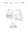
- FIG. 1is a rear view of a skin incision apparatus, according to the invention
- FIG. 1Ais a front view of the skin incision apparatus. Selected parts are shown in hidden line.
- FIG. 2is a bottom plan view of the apparatus
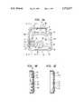
- FIG. 3is an inside view of a first housing section of the apparatus
- FIG. 3Ais a sectional view taken along the line 3A--3A in FIG. 3;
- FIG. 3Bis a sectional view taken along the line 3B--3B in FIG. 3;
- FIG. 4is an inside view of a second housing section of the apparatus
- FIG. 4Ais a sectional view taken along the line 4A--4A in FIG. 4;
- FIG. 4Bis a sectional view taken along the line 4B--4B in FIG. 4;
- FIG. 5Ais a front view of a pivot arm and a cutting edge employed in this invention.
- FIG. 5Bis a rear view of the pivot arm and the cutting edge
- FIG. 6Ais a front view of a trigger mechanism or plunger employed in this invention.
- FIG. 6Bis a bottom view of the trigger mechanism
- FIG. 7is an enlarged front view of a torsion spring
- FIG. 8Ais a side view of a spring post
- FIG. 8Bis a front view of the spring post
- FIG. 8Cis a rear view of the spring post
- FIG. 9is an inside view of a first housing section with the pivot arm, and the spring and the spring post installed in an installation position;
- FIG. 9Ais a sectional view taken along the line 9A--9A in FIG. 9;
- FIG. 9Bis a sectional view taken along the line 9B--9B in FIG. 9;
- FIG. 10is a front view of the apparatus with a portion of the base of the front housing section broken away to show the interior;
- FIG. 10Ais a sectional view taken along the line 10A--10A in FIG. 10;
- FIG. 11is a top view of a turntable for automatically assembly with various components shown broken away or in hidden line.
- FIG. 1a rear view of an apparatus for skin incision which has been identified by the numeral 20.
- the skin incision apparatus 20has a housing 22 having a pair of housing sections 24 and 26, only one section, the rear section 24, seen in FIG. 1.
- a trigger mechanism 28 of and for activating the skin incision apparatus 20projects through an opening 30, as best seen in FIGS. 3 and 4, formed between the two sections 24 and 26 of the housing 22.
- the trigger mechanism 28is also referred to as a plunger.
- the rear section 24 of the housing 22has a hole 32 through which a portion of a spring post 34 projects.
- the skin incision apparatus 20has a keeper or safety device 38 which can be removed from a safety position surrounding a portion of the trigger mechanism 28 to prevent inadvertent operation.
- the keeper 38is shown removed in FIG. 1A.
- the front housing section 26 with the surface configuration not shown and selected components of the skin incision apparatus 20 are shown in hidden lineis seen in FIG. 1A.
- the skin incision apparatus 20has, in addition to the housing 22, the trigger mechanism 28, and the spring post 34, not seen in FIG. 1A, a pivot arm 40 which carries a blade 42 , and a torsion spring 44.
- the pivot arm 40, the spring post 34, and the torsion spring 44are located in an inner space 46 defined by the housing sections 24 and 26.
- a typical unithas a height A of approximately 1.19 inches with a bottom length B of 1.125 inches; the top length being slightly less than the bottom length.
- the unithas width C, as seen in FIG. 2, of about 0.4375 inches.
- Each of the housing sections 24 and 26has a base 50 and four walls 52, 54, 56, and 58 projecting from the base 50.
- the bottom wall 54 of each of the housing sections 24 and 26is shown in FIG. 2.
- the bottom walls 54f and 54rare joined together to define the slot 48, through which the blade 42 passes during operation or when activated.
- the base 50r and the four walls 52r, 54r, 56r, and 58r projecting from the base 50r of the rear housing section 24are seen in FIG. 3.
- the four walls 52r, 54r, 56r, and 58r and base 50rdefine a portion of the inner space 46. Located generally where two walls join to form a corner is an opening 60.
- the rear housing section 24has a raised portion or bulkhead 62 projecting from the base 50r.
- the raised portion 62defines a convoluted cam channel 64.
- the post 68acts as a pivot point for the pivot arm 40 containing the blade 42.
- the rear housing 24has a second circular boss 70 defining an indentation 72 for receiving a portion of the spring post 34.
- the indentation 72has a bi-level surface 74 at the base 50r; the bi-level surface includes a raised level 76 on either side of a lower groove 78. In the center of the lower groove 78 is the hole 32 seen in FIG. 1.
- the rear housing section 24has a post 80 that projects upward.
- the post 80engages the base 50f of the front housing section 26 as described below.
- the base 50rin addition, forms a ridge 82 upon which the trigger mechanism 28 slides.
- the top wall 58r of the housing section 24has a projecting member 84, a stop member, which projects into the inner space 46 for limiting movement of the trigger mechanism 28.
- the base 50f and the four walls 52f, 54f, 56f, and 58f projecting from the base 50r of the front housing sections 26are seen in FIG. 4.
- the four walls 52f, 54f, 56f, and 58f and base 50fdefine a portion of the inner space 46.
- pins 86Located generally in the locations where two walls join to form a corner are pins 86, as seen in FIGS. 4, 4A, and 4B, which are received by the openings 60 in the rear housing section 24.
- the front housing section 26has a semi-circular boss 88 for holding the pivot arm 40 containing the blade 50 in position, as explained below.
- the top wall 58f of the housing section 26has a projecting member 84, a stop member, which projects into the inner space 46 for limiting movement of the trigger mechanism 28.
- the front housing section 26has a circular boss 90 defining an indentation 92 for receiving a portion of the spring post 34 as seen in FIGS. 4 and 4B.
- the indentation 92has a raised protrusion 94 at the base 50f.
- the front housing section 26has a dimple 96 for receiving the tip of the post 80 that projects from the rear housing section 24.
- the base 50fforms a ridge 82 upon which the trigger mechanism 28 slides.
- the pivot arm 40has a shoulder 98 defined by two different level surfaces.
- the shoulder 98is engaged by the torsion spring 44, as defined below.
- a recess 100is formed for part of the shoulder 98, and is shown in hidden line.
- the blade 42, a triangular blade with a cutting edge 102 and a sharpened apex 104is coupled to the pivot arm 40.
- the blade 42may be secured to the pivot arm 40 by any conventional means and is scalpel-like in appearance and function.
- a keeper section 106Located on the top of the pivot arm 40 is a keeper section 106 which acts with the end of the trigger mechanism 28 to retain the pivot arm 40 in a first position prior to actuation of the skin incision apparatus 20.
- the pivot arm 40has an extended cam follower rod 108 which extends into the convoluted cam channel 64.
- the convoluted cam surface of the cam channel 64controls the movement of the pivot arm 40 and, therefore, of the cutting edge 102 of the blade 42 when the skin incision apparatus 20 is activated.
- a raised boss 110projects from the pivot arm 40 to define an elongated aperture 114.
- the trigger mechanism 28has a sloping front end 116 as seen in FIG. 6A which acts with the keeper section 106 of the pivot arm 40 during operation.
- the trigger mechanism 28also contains a top channel 118 which abuts against the stop member 84 of the housing 22.
- the trigger mechanism 28also referred to as a plunger member, has a hollow section 120 through which the keeper section 106 of the pivot arm 40 passes as it moves, as explained below.
- FIG. 7is an enlarged side view of the torsion spring 44.
- the spring 44has a core 122 and a pair of legs 124 and 126.
- the first leg 124projects inwardly and bisects the core 122.
- the second leg 126extends generally out at a tangent from the core 122.
- the second leg 126has a bend or jog 128, which facilitates assembly as discussed below.
- the spring post 34is adapted to carry the spring 44.
- the spring post 34generally has a cylindrical shape and includes a cylindrical base portion 130, a raised detent portion 132, and a reduced diameter cylindrical portion 134.
- the raised detent portion 132projects from the cylindrical base portion 130 to a first end 136.
- the raised detent portion 132has a circular segment detent portion 138 projecting from the cylindrical base portion 130.
- a cylindrical guide portion 140projects from the detent portion 138.
- the cylindrical guide portion 140has an outside diameter no greater than the width of the circular segment detent portion 138 and is received by the hole 32 in the rear housing section 24, as seen in FIGS. 1 and 3.
- a turn element 142 for setting or loading the spring 34, as described below,projects from the end of the cylindrical guide portion 140.
- the turn element 142similar to the circular segment detent portion 138, has a pair of parallel edges 144 spaced by circular arc edges, in a preferred embodiment, as best seen in FIG. 8B.
- the reduced diameter cylindrical portion 134 of the spring post 34extends from the base portion 130 to a second end 146.
- a slot 148 in the reduced diameter cylindrical portion 134extends from the second end 146 to approximately the cylindrical base portion 130.
- the intersection of the base portion 130 with the reduced diameter cylindrical portion 134defines a shoulder 150.
- the skin incision apparatus 20is assembled by placing the pivot arm 40 in the rear housing section 24 such that the extended cam follower rod 108 is received by the convoluted cam channel 64 and the elongated aperture 114 defined by the raised boss 110, as best seen in FIGS. 9A and 5B, receives the extending rod 68 of the rear housing section 24.
- the pivot arm 40is positioned in the first position, the actuation position, with the keeper section 106 to the left in FIG. 9.
- the leg 124Prior to installing the torsion spring 44 and the spring post 34, the leg 124 is received by the slot 148 in the reduced diameter cylindrical portion 134 of the spring post 34, such that the core 122 of the spring 44 encircles the reduced diameter portion 134 of the post 34.
- the spring 44is located on the shoulder 150 defined by the base portion 130 and the reduced diameter cylindrical portion 134.
- the spring post 34is positioned on the rear housing section 24 so that the raised detent portion 132 of the spring post 34 is received by the second circular boss 70 on the base 50 of the rear housing section 24.
- the circular segment detent portion 138is positioned so that it does not align with the lower groove 78 of the bi-level surface 74, as best seen in FIG. 9B.
- the turn element 142in a preferred embodiment, is located in the hole 32 in the base 50 of the rear housing section 26.
- the second leg 128is received by the shoulder 98 in the pivot arm 40.
- the bend or jog 128 in the leg 126 of the spring 44reduces the chance of interference with the front housing section 26 during assembly.
- the trigger mechanism 28is installed on the ridge 82.
- the sloping front end 116is positioned to engage the keeper section 106 of the pivot arm 40.
- the top channel 118is positioned to receive the stop member 84.
- the keeper or safety device 38can be installed on the trigger mechanism 28 at this time.
- the front housing section 26is positioned on top of the rear housing section 24 such that the pins 86, as seen in FIG. 4, are received by the openings 60, as seen in FIG. 9, in the rear housing section 24.
- the semi-circular boss 88 of the front housing section 26is positioned above the pivot arm 40, in proximity to where the blade 42 is mounted to the pivot arm 40.
- the reduced diameter cylindrical portion 134 of the spring post 34is received in the indentation 92 defined by the circular boss 90 of the front housing section 26.
- the slot 148is not aligned with the raised protrusion 94 in the circular boss 90, at least initially. The position of the slot 148 is shown in FIG. 9.
- the turn element 142is rotated using a tool 154, as seen in FIG. 11, which complements the shape of the turn element.
- the turn element 142is turned clockwise as seen in FIGS. 9 and 10, and counterclockwise as seen in FIG. 1.
- the rotation of the turn element 142rotates the spring post 34, therein moving the first leg 124 of the spring 44 which is received by the slot 148 in the reduced diameter cylindrical portion 134 of the spring post 34.
- the first leg 124is the movable end or leg to tension the spring 44.
- the second leg 126which is received by the shoulder 98 of the pivot arm 40, is the stationary end.
- the turn element 142is rotated until the circular segment detent portion 138 of the spring post 34 aligns with the lower groove 78 of the bi-level surface 74 of the second circular boss 70 of the rear housing section 24 and the raised protrusion 94 on the front housing section 26 is received by the slot 148 of the spring post 34. With the alignment, the walls 52, 54, 56, and 58 of the two housing sections 24 and 26 do mesh, as shown in FIG. 10A.
- the skin incision apparatus 20is ready to operate.
- the keeper 38is removed from the trigger mechanism 28.
- the trigger mechanism 28is pushed inward, to the left in FIG. 1A.
- the sloping front end 116pushes the pivot arm 40 towards the left until the pivot arm 40 clears the sloping front end 116 of the trigger mechanism 28.
- the spring 44pivots the entire pivot arm 40.
- the second leg 126rotates and is the movable end, and the first leg 124, the stationary end, is held by the spring post 34 which is held by the bi-level surface 74 of the rear housing section 24 and the raised protrusion 94 of the front housing section 26.
- the pivot arm 40moves with the extended cam follower rod 108 following the convoluted cam channel 64.
- the shape of the convoluted cam channel 64converts the generally arcuate motion of the pivot arm 40 into a linear portion for a segment of the motion of the blade 42.
- the operationis such that the apex 104 of the blade 42 punctures the skin and thereafter the cutting edge 102 incises the skin.
- the blade 42including the apex 104, is withdrawn from the skin back into the housing 22.
- the turntable 156has a plurality of orifices 158 which are of a shape similar to that of the rear housing section 24, with an additional notch for the placing of the keeper 38.
- the turntable 156has eight (8) orifices 158.
- the turntable 158has a plate 160, shown in hidden line, which is generally annular and underlies all of the orifices 158, except one as explained below, for retaining the skin incision apparatus 20.
- the rear housing section 24slides into an orifice 158 from a ramp 162 at station I.
- the turntableis rotated, by a motor mechanism 164 shown in hidden line, to the next position, or station.
- the pivot arm 40is loaded by a robotic arm, not shown, at the next station (station II) into the rear housing section 24.
- the trigger mechanism 28 and keeper 38are loaded as a unit.
- the keeper 38is loaded on the trigger mechanism 28 prior to installation in station III.
- the leg 124 of the spring 44is received by the slot 148 in the reduced diameter cylindrical portion 134 of the spring post 34, such that the core 122 of the spring 44 encircles the reduced diameter portion 134 of the post 34.
- the spring 44is located on the shoulder 150 defined by the base portion 130 and the reduced diameter cylindrical portion 134.
- the spring post 34is positioned on the rear housing section 24 (in station IV) so that the raised detent portion 132 of the spring post 34 is received by the second circular boss 70 on the base 50 of the rear housing section 26, similar to that described above with reference FIGS. 9 and 9B.
- the second leg 128is received by the shoulder 98 of the pivot arm 40.
- the front housing section 26With all the parts located on the rear housing section 24, the front housing section 26 is positioned on the rear housing section 24 in station V.
- the pins 86, as seen in FIG. 4, of the front housing section 26are received by the openings 60 in the rear housing section 24.
- the walls 52, 54, 56, and 58 of the two housing sections 24 and 26do not engage completely.
- the turntablerotates moving the housing sections 24 and 26 under a spring loaded plate 166, which urges the front housing section 26 into engagement with the rear housing section 24.
- the spring loaded plate 166overlies stations VI and VII. In a preferred embodiment, no operation occurs at station VI.
- a tool 154moves into engagement with the turn element 142 of the spring post 34, as seen in FIGS. 1 and 9B, rotates the spring post 34, therein moving the first leg 124 of the spring 44 which is received by the slot 148 in the reduced diameter cylindrical portion 134 of the spring post 34.
- the turn element 142is rotated until the circular segment detent portion 138 of the spring post 34 aligns with the lower groove 78 of the bi-level surface 74.
- the spring loaded plate 166urges the front housing section into engagement with the rear housing section.
- the turntable 156rotates to a final station (station VIII) where the underlying plate 160 is not located.
- the skin incision apparatus 20drops to a chute 168 or a conveyor, to move to a packaging section, not shown. It is recognized that the turntable 156 could have fewer or more stations. It is also recognized that multiple parts could be loaded at one station or a plurality of stations could have the same operation being performed and the turntable turns a plurality of orifices at one time. In addition, it is recognized that there are other methods of assembling the skin incision apparatus 20 automatically.
Landscapes
- Health & Medical Sciences (AREA)
- Surgery (AREA)
- Life Sciences & Earth Sciences (AREA)
- Biomedical Technology (AREA)
- Nuclear Medicine, Radiotherapy & Molecular Imaging (AREA)
- Engineering & Computer Science (AREA)
- Dermatology (AREA)
- Heart & Thoracic Surgery (AREA)
- Medical Informatics (AREA)
- Molecular Biology (AREA)
- Animal Behavior & Ethology (AREA)
- General Health & Medical Sciences (AREA)
- Public Health (AREA)
- Veterinary Medicine (AREA)
- Surgical Instruments (AREA)
Abstract
Description
Claims (8)
Priority Applications (2)
| Application Number | Priority Date | Filing Date | Title |
|---|---|---|---|
| US08/718,774US5772677A (en) | 1996-09-24 | 1996-09-24 | Incision device capable of automatic assembly and a method of assembly |
| US09/022,072US6010519A (en) | 1996-09-24 | 1998-02-11 | Incision device capable of automatic assembly and a method of assembly |
Applications Claiming Priority (1)
| Application Number | Priority Date | Filing Date | Title |
|---|---|---|---|
| US08/718,774US5772677A (en) | 1996-09-24 | 1996-09-24 | Incision device capable of automatic assembly and a method of assembly |
Related Child Applications (1)
| Application Number | Title | Priority Date | Filing Date |
|---|---|---|---|
| US09/022,072DivisionUS6010519A (en) | 1996-09-24 | 1998-02-11 | Incision device capable of automatic assembly and a method of assembly |
Publications (1)
| Publication Number | Publication Date |
|---|---|
| US5772677Atrue US5772677A (en) | 1998-06-30 |
Family
ID=24887481
Family Applications (2)
| Application Number | Title | Priority Date | Filing Date |
|---|---|---|---|
| US08/718,774Expired - LifetimeUS5772677A (en) | 1996-09-24 | 1996-09-24 | Incision device capable of automatic assembly and a method of assembly |
| US09/022,072Expired - LifetimeUS6010519A (en) | 1996-09-24 | 1998-02-11 | Incision device capable of automatic assembly and a method of assembly |
Family Applications After (1)
| Application Number | Title | Priority Date | Filing Date |
|---|---|---|---|
| US09/022,072Expired - LifetimeUS6010519A (en) | 1996-09-24 | 1998-02-11 | Incision device capable of automatic assembly and a method of assembly |
Country Status (1)
| Country | Link |
|---|---|
| US (2) | US5772677A (en) |
Cited By (105)
| Publication number | Priority date | Publication date | Assignee | Title |
|---|---|---|---|---|
| US20050033341A1 (en)* | 2003-07-28 | 2005-02-10 | Vreeke Mark S. | Swing lance with integrated sensor |
| US20050038465A1 (en)* | 2003-08-15 | 2005-02-17 | Stat Medical Devices, Inc. | Adjustable lancet device and method |
| US20050038464A1 (en)* | 2003-08-15 | 2005-02-17 | Stat Medical Devices, Inc. | Adjustable lancet device and method |
| US20050256536A1 (en)* | 2004-05-13 | 2005-11-17 | Grundeman Paul F | Device for making a cut in a tissue |
| US7025774B2 (en) | 2001-06-12 | 2006-04-11 | Pelikan Technologies, Inc. | Tissue penetration device |
| US20060106411A1 (en)* | 2004-11-16 | 2006-05-18 | Stat Medical Devices Inc. | Adjustable disposable/single-use blade lancet device and method |
| US20060116705A1 (en)* | 2004-11-30 | 2006-06-01 | Stat Medical Devices, Inc. | Disposable or single-use lancet device and method |
| US20060241668A1 (en)* | 2005-01-28 | 2006-10-26 | Stat Medical Devices, Inc. | Multi-lancet unit, method and lancet device using the multi-lancet unit, and method of assembling and/or making the multi-lancet unit |
| US7198606B2 (en) | 2002-04-19 | 2007-04-03 | Pelikan Technologies, Inc. | Method and apparatus for a multi-use body fluid sampling device with analyte sensing |
| US20070095178A1 (en)* | 2005-11-03 | 2007-05-03 | Stat Medical Devices, Inc. | Disposable/single-use blade lancet device and method |
| US7229458B2 (en) | 2002-04-19 | 2007-06-12 | Pelikan Technologies, Inc. | Method and apparatus for penetrating tissue |
| US7232451B2 (en) | 2002-04-19 | 2007-06-19 | Pelikan Technologies, Inc. | Method and apparatus for penetrating tissue |
| US7244265B2 (en) | 2002-04-19 | 2007-07-17 | Pelikan Technologies, Inc. | Method and apparatus for penetrating tissue |
| US7258693B2 (en) | 2002-04-19 | 2007-08-21 | Pelikan Technologies, Inc. | Device and method for variable speed lancet |
| US7291117B2 (en) | 2002-04-19 | 2007-11-06 | Pelikan Technologies, Inc. | Method and apparatus for penetrating tissue |
| US7297151B2 (en) | 2002-04-19 | 2007-11-20 | Elikan Technologies, Inc. | Method and apparatus for body fluid sampling with improved sensing |
| US7297122B2 (en) | 2002-04-19 | 2007-11-20 | Pelikan Technologies, Inc. | Method and apparatus for penetrating tissue |
| US7316700B2 (en) | 2001-06-12 | 2008-01-08 | Pelikan Technologies, Inc. | Self optimizing lancing device with adaptation means to temporal variations in cutaneous properties |
| US7331931B2 (en) | 2002-04-19 | 2008-02-19 | Pelikan Technologies, Inc. | Method and apparatus for penetrating tissue |
| US7344894B2 (en) | 2001-10-16 | 2008-03-18 | Agilent Technologies, Inc. | Thermal regulation of fluidic samples within a diagnostic cartridge |
| US7344507B2 (en) | 2002-04-19 | 2008-03-18 | Pelikan Technologies, Inc. | Method and apparatus for lancet actuation |
| US20080092241A1 (en)* | 2006-10-11 | 2008-04-17 | Media Machines, Inc. | Provision and use of digital rights data for embedded content over networked systems |
| US7371247B2 (en) | 2002-04-19 | 2008-05-13 | Pelikan Technologies, Inc | Method and apparatus for penetrating tissue |
| US7374544B2 (en) | 2002-04-19 | 2008-05-20 | Pelikan Technologies, Inc. | Method and apparatus for penetrating tissue |
| US7410468B2 (en) | 2002-04-19 | 2008-08-12 | Pelikan Technologies, Inc. | Method and apparatus for penetrating tissue |
| US20080243159A1 (en)* | 2007-03-30 | 2008-10-02 | Stat Medical Devices, Inc. | Lancet device with combined trigger and cocking mechanism and method |
| US7485128B2 (en) | 2002-04-19 | 2009-02-03 | Pelikan Technologies, Inc. | Method and apparatus for penetrating tissue |
| US7491178B2 (en) | 2002-04-19 | 2009-02-17 | Pelikan Technologies, Inc. | Method and apparatus for penetrating tissue |
| US7524293B2 (en) | 2002-04-19 | 2009-04-28 | Pelikan Technologies, Inc. | Method and apparatus for penetrating tissue |
| US7537571B2 (en) | 2001-06-12 | 2009-05-26 | Pelikan Technologies, Inc. | Integrated blood sampling analysis system with multi-use sampling module |
| US7547287B2 (en) | 2002-04-19 | 2009-06-16 | Pelikan Technologies, Inc. | Method and apparatus for penetrating tissue |
| US7563232B2 (en) | 2002-04-19 | 2009-07-21 | Pelikan Technologies, Inc. | Method and apparatus for penetrating tissue |
| US7604592B2 (en) | 2003-06-13 | 2009-10-20 | Pelikan Technologies, Inc. | Method and apparatus for a point of care device |
| US20100010528A1 (en)* | 2008-07-09 | 2010-01-14 | Guoping Shi | Disposable single-swing-arm incision safety lancet |
| US20100010529A1 (en)* | 2008-07-09 | 2010-01-14 | Guoping Shi | Disposable incision safety lancet |
| US7648468B2 (en) | 2002-04-19 | 2010-01-19 | Pelikon Technologies, Inc. | Method and apparatus for penetrating tissue |
| US7666149B2 (en) | 1997-12-04 | 2010-02-23 | Peliken Technologies, Inc. | Cassette of lancet cartridges for sampling blood |
| US7674232B2 (en) | 2002-04-19 | 2010-03-09 | Pelikan Technologies, Inc. | Method and apparatus for penetrating tissue |
| US7682318B2 (en) | 2001-06-12 | 2010-03-23 | Pelikan Technologies, Inc. | Blood sampling apparatus and method |
| US7699791B2 (en) | 2001-06-12 | 2010-04-20 | Pelikan Technologies, Inc. | Method and apparatus for improving success rate of blood yield from a fingerstick |
| US7717863B2 (en) | 2002-04-19 | 2010-05-18 | Pelikan Technologies, Inc. | Method and apparatus for penetrating tissue |
| US7749174B2 (en) | 2001-06-12 | 2010-07-06 | Pelikan Technologies, Inc. | Method and apparatus for lancet launching device intergrated onto a blood-sampling cartridge |
| US7780631B2 (en) | 1998-03-30 | 2010-08-24 | Pelikan Technologies, Inc. | Apparatus and method for penetration with shaft having a sensor for sensing penetration depth |
| USD623742S1 (en) | 2009-12-11 | 2010-09-14 | Facet Technologies, Llc | Lancing device |
| US20100256526A1 (en)* | 2009-04-03 | 2010-10-07 | Herbert Harttig | Apparatus for acquiring and analyzing a blood sample |
| US7822454B1 (en) | 2005-01-03 | 2010-10-26 | Pelikan Technologies, Inc. | Fluid sampling device with improved analyte detecting member configuration |
| US20100274273A1 (en)* | 2007-06-19 | 2010-10-28 | Steven Schraga | Lancet device with depth adjustment and lancet removal system and method |
| US7850621B2 (en) | 2003-06-06 | 2010-12-14 | Pelikan Technologies, Inc. | Method and apparatus for body fluid sampling and analyte sensing |
| US7862520B2 (en) | 2002-04-19 | 2011-01-04 | Pelikan Technologies, Inc. | Body fluid sampling module with a continuous compression tissue interface surface |
| US7892185B2 (en) | 2002-04-19 | 2011-02-22 | Pelikan Technologies, Inc. | Method and apparatus for body fluid sampling and analyte sensing |
| US7892183B2 (en) | 2002-04-19 | 2011-02-22 | Pelikan Technologies, Inc. | Method and apparatus for body fluid sampling and analyte sensing |
| US7901362B2 (en) | 2002-04-19 | 2011-03-08 | Pelikan Technologies, Inc. | Method and apparatus for penetrating tissue |
| US7909778B2 (en) | 2002-04-19 | 2011-03-22 | Pelikan Technologies, Inc. | Method and apparatus for penetrating tissue |
| US7947057B2 (en) | 1998-06-11 | 2011-05-24 | Stat Medical Devices, Inc. | Lancet having adjustable penetration depth |
| US20110144537A1 (en)* | 2009-12-16 | 2011-06-16 | Facet Technologies, Llc | Blood sampling device with dual-link drive mechanism |
| US7976476B2 (en) | 2002-04-19 | 2011-07-12 | Pelikan Technologies, Inc. | Device and method for variable speed lancet |
| US8043318B2 (en) | 2007-02-08 | 2011-10-25 | Stat Medical Devices, Inc. | Push-button lance device and method |
| US20110264131A1 (en)* | 2008-07-30 | 2011-10-27 | Medipurpose Pte Ltd | Device For Performing An Incision |
| US8197421B2 (en) | 2002-04-19 | 2012-06-12 | Pelikan Technologies, Inc. | Method and apparatus for penetrating tissue |
| US8221334B2 (en) | 2002-04-19 | 2012-07-17 | Sanofi-Aventis Deutschland Gmbh | Method and apparatus for penetrating tissue |
| US8262614B2 (en) | 2003-05-30 | 2012-09-11 | Pelikan Technologies, Inc. | Method and apparatus for fluid injection |
| US8267870B2 (en) | 2002-04-19 | 2012-09-18 | Sanofi-Aventis Deutschland Gmbh | Method and apparatus for body fluid sampling with hybrid actuation |
| US8282576B2 (en) | 2003-09-29 | 2012-10-09 | Sanofi-Aventis Deutschland Gmbh | Method and apparatus for an improved sample capture device |
| US8337421B2 (en) | 2001-06-12 | 2012-12-25 | Sanofi-Aventis Deutschland Gmbh | Tissue penetration device |
| US8353924B2 (en) | 1999-11-02 | 2013-01-15 | Stat Medical Devices, Inc. | Single use lancet assembly |
| US8360992B2 (en) | 2002-04-19 | 2013-01-29 | Sanofi-Aventis Deutschland Gmbh | Method and apparatus for penetrating tissue |
| US8556829B2 (en) | 2002-04-19 | 2013-10-15 | Sanofi-Aventis Deutschland Gmbh | Method and apparatus for penetrating tissue |
| US8574895B2 (en) | 2002-12-30 | 2013-11-05 | Sanofi-Aventis Deutschland Gmbh | Method and apparatus using optical techniques to measure analyte levels |
| US8641644B2 (en) | 2000-11-21 | 2014-02-04 | Sanofi-Aventis Deutschland Gmbh | Blood testing apparatus having a rotatable cartridge with multiple lancing elements and testing means |
| US8652831B2 (en) | 2004-12-30 | 2014-02-18 | Sanofi-Aventis Deutschland Gmbh | Method and apparatus for analyte measurement test time |
| US8668656B2 (en) | 2003-12-31 | 2014-03-11 | Sanofi-Aventis Deutschland Gmbh | Method and apparatus for improving fluidic flow and sample capture |
| US20140088633A1 (en)* | 2012-09-27 | 2014-03-27 | Facet Technologies, Llc | Depth-adjust mechanism for lancing device |
| US8702624B2 (en) | 2006-09-29 | 2014-04-22 | Sanofi-Aventis Deutschland Gmbh | Analyte measurement device with a single shot actuator |
| US8715309B2 (en) | 2002-04-29 | 2014-05-06 | Steven Schraga | Lancet device |
| US8721671B2 (en) | 2001-06-12 | 2014-05-13 | Sanofi-Aventis Deutschland Gmbh | Electric lancet actuator |
| US8784335B2 (en) | 2002-04-19 | 2014-07-22 | Sanofi-Aventis Deutschland Gmbh | Body fluid sampling device with a capacitive sensor |
| US8814896B2 (en) | 1999-11-02 | 2014-08-26 | Stat Medical Devices, Inc. | Single use lancet assembly |
| US8828203B2 (en) | 2004-05-20 | 2014-09-09 | Sanofi-Aventis Deutschland Gmbh | Printable hydrogels for biosensors |
| US8965476B2 (en) | 2010-04-16 | 2015-02-24 | Sanofi-Aventis Deutschland Gmbh | Tissue penetration device |
| USD728787S1 (en) | 2014-04-14 | 2015-05-05 | Intrinsyk, LLC | Lancet assembly |
| US9144401B2 (en) | 2003-06-11 | 2015-09-29 | Sanofi-Aventis Deutschland Gmbh | Low pain penetrating member |
| USD742004S1 (en) | 2014-02-18 | 2015-10-27 | “HTL-STREFA” Spólka Akcyjna | Skin incision device |
| US9226699B2 (en) | 2002-04-19 | 2016-01-05 | Sanofi-Aventis Deutschland Gmbh | Body fluid sampling module with a continuous compression tissue interface surface |
| US9248267B2 (en) | 2002-04-19 | 2016-02-02 | Sanofi-Aventis Deustchland Gmbh | Tissue penetration device |
| US9314194B2 (en) | 2002-04-19 | 2016-04-19 | Sanofi-Aventis Deutschland Gmbh | Tissue penetration device |
| US9351680B2 (en) | 2003-10-14 | 2016-05-31 | Sanofi-Aventis Deutschland Gmbh | Method and apparatus for a variable user interface |
| US9375169B2 (en) | 2009-01-30 | 2016-06-28 | Sanofi-Aventis Deutschland Gmbh | Cam drive for managing disposable penetrating member actions with a single motor and motor and control system |
| US9386944B2 (en) | 2008-04-11 | 2016-07-12 | Sanofi-Aventis Deutschland Gmbh | Method and apparatus for analyte detecting device |
| US9427532B2 (en) | 2001-06-12 | 2016-08-30 | Sanofi-Aventis Deutschland Gmbh | Tissue penetration device |
| US9474479B2 (en) | 2012-06-18 | 2016-10-25 | Facet Technologies, Llc | Uni-directional drive mechanism for lancing device |
| USD786431S1 (en)* | 2015-12-01 | 2017-05-09 | Global Resources International, Inc. | Infant heel incision device |
| USD786432S1 (en)* | 2015-12-01 | 2017-05-09 | Global Resources International, Inc. | Infant heel incision device |
| US20170208825A1 (en)* | 2016-01-21 | 2017-07-27 | Alan Backus | Gaseous transfer device |
| US9775553B2 (en) | 2004-06-03 | 2017-10-03 | Sanofi-Aventis Deutschland Gmbh | Method and apparatus for a fluid sampling device |
| US9795747B2 (en) | 2010-06-02 | 2017-10-24 | Sanofi-Aventis Deutschland Gmbh | Methods and apparatus for lancet actuation |
| US9820684B2 (en) | 2004-06-03 | 2017-11-21 | Sanofi-Aventis Deutschland Gmbh | Method and apparatus for a fluid sampling device |
| USD806246S1 (en) | 2016-02-25 | 2017-12-26 | Steven Schraga | Lancet cover |
| US10034627B2 (en) | 2014-01-28 | 2018-07-31 | Intrinsyk, LLC | Lancet assembly |
| US10070811B2 (en) | 2014-06-26 | 2018-09-11 | Stat Medical Devices, Inc. | Lancing device with depth adjustment and lancet removal system and method |
| US11033212B2 (en) | 2014-08-01 | 2021-06-15 | Tasso, Inc. | Devices, systems and methods for gravity-enhanced microfluidic collection, handling and transferring of fluids |
| US11395614B2 (en) | 2012-01-25 | 2022-07-26 | Tasso, Inc. | Methods, systems, and devices relating to open microfluidic channels |
| US11510659B2 (en) | 2018-09-14 | 2022-11-29 | Tasso, Inc. | Bodily fluid collection devices and related methods |
| US11633136B2 (en) | 2021-02-26 | 2023-04-25 | Tasso, Inc. | Bodily fluid collection devices and related methods |
| US11642057B2 (en) | 2015-12-21 | 2023-05-09 | Tasso, Inc. | Devices, systems and methods for actuation and retraction in fluid collection |
| USD1098429S1 (en) | 2024-09-25 | 2025-10-14 | Jaroslaw Moleda | Heel incision safety lancet |
Families Citing this family (42)
| Publication number | Priority date | Publication date | Assignee | Title |
|---|---|---|---|---|
| US7364577B2 (en) | 2002-02-11 | 2008-04-29 | Sherwood Services Ag | Vessel sealing system |
| ES2262639T3 (en) | 2001-04-06 | 2006-12-01 | Sherwood Services Ag | SHUTTER AND DIVIDER OF GLASSES WITH BUMPER MEMBERS N OCONDUCTIVES. |
| US7004928B2 (en) | 2002-02-08 | 2006-02-28 | Rosedale Medical, Inc. | Autonomous, ambulatory analyte monitor or drug delivery device |
| DE20213607U1 (en) | 2002-02-21 | 2003-07-03 | Paul Hartmann AG, 89522 Heidenheim | Blood analyzer for the determination of an analyte |
| US7931649B2 (en) | 2002-10-04 | 2011-04-26 | Tyco Healthcare Group Lp | Vessel sealing instrument with electrical cutting mechanism |
| US7052652B2 (en)* | 2003-03-24 | 2006-05-30 | Rosedale Medical, Inc. | Analyte concentration detection devices and methods |
| US8221332B2 (en) | 2003-11-12 | 2012-07-17 | Facet Technologies, Llc | Multi-lancet cartridge and lancing device |
| EP1684634A2 (en)* | 2003-11-12 | 2006-08-02 | Facet Technologies, LLC | Lancing device and multi-lancet cartridge |
| US20080082117A1 (en)* | 2003-11-12 | 2008-04-03 | Facet Technologies, Llc | Lancing device |
| US7367976B2 (en) | 2003-11-17 | 2008-05-06 | Sherwood Services Ag | Bipolar forceps having monopolar extension |
| WO2005084557A1 (en)* | 2004-03-02 | 2005-09-15 | Facet Technologies, Llc | Compact multi-use lancing device |
| US7377904B2 (en) | 2004-04-16 | 2008-05-27 | Facet Technologies, Llc | Cap displacement mechanism for lancing device and multi-lancet cartridge |
| US7837633B2 (en) | 2004-06-30 | 2010-11-23 | Facet Technologies, Llc | Lancing device and multi-lancet cartridge |
| US7488298B2 (en)* | 2004-10-08 | 2009-02-10 | Roche Diagnostics Operations, Inc. | Integrated lancing test strip with capillary transfer sheet |
| US7909823B2 (en) | 2005-01-14 | 2011-03-22 | Covidien Ag | Open vessel sealing instrument |
| US7479118B2 (en) | 2005-02-07 | 2009-01-20 | Roche Diagnostics Operations, Inc. | Lancet protective cap |
| US7695442B2 (en) | 2005-04-12 | 2010-04-13 | Roche Diagnostics Operations, Inc. | Integrated lancing test strip with retractable lancet |
| US20060281187A1 (en)* | 2005-06-13 | 2006-12-14 | Rosedale Medical, Inc. | Analyte detection devices and methods with hematocrit/volume correction and feedback control |
| US8801631B2 (en) | 2005-09-30 | 2014-08-12 | Intuity Medical, Inc. | Devices and methods for facilitating fluid transport |
| US7922953B2 (en) | 2005-09-30 | 2011-04-12 | Covidien Ag | Method for manufacturing an end effector assembly |
| EP1928302B1 (en) | 2005-09-30 | 2012-08-01 | Intuity Medical, Inc. | Fully integrated wearable or handheld monitor |
| US9833183B2 (en)* | 2008-05-30 | 2017-12-05 | Intuity Medical, Inc. | Body fluid sampling device—sampling site interface |
| WO2009148624A1 (en) | 2008-06-06 | 2009-12-10 | Intuity Medical, Inc. | Detection meter and mode of operation |
| EP3984454A1 (en) | 2008-06-06 | 2022-04-20 | Intuity Medical, Inc. | Medical diagnostic devices and methods |
| US8142473B2 (en) | 2008-10-03 | 2012-03-27 | Tyco Healthcare Group Lp | Method of transferring rotational motion in an articulating surgical instrument |
| US8016827B2 (en) | 2008-10-09 | 2011-09-13 | Tyco Healthcare Group Lp | Apparatus, system, and method for performing an electrosurgical procedure |
| US8114122B2 (en) | 2009-01-13 | 2012-02-14 | Tyco Healthcare Group Lp | Apparatus, system, and method for performing an electrosurgical procedure |
| US8187273B2 (en) | 2009-05-07 | 2012-05-29 | Tyco Healthcare Group Lp | Apparatus, system, and method for performing an electrosurgical procedure |
| US8246618B2 (en) | 2009-07-08 | 2012-08-21 | Tyco Healthcare Group Lp | Electrosurgical jaws with offset knife |
| US8162965B2 (en)* | 2009-09-09 | 2012-04-24 | Tyco Healthcare Group Lp | Low profile cutting assembly with a return spring |
| US8133254B2 (en) | 2009-09-18 | 2012-03-13 | Tyco Healthcare Group Lp | In vivo attachable and detachable end effector assembly and laparoscopic surgical instrument and methods therefor |
| US8112871B2 (en) | 2009-09-28 | 2012-02-14 | Tyco Healthcare Group Lp | Method for manufacturing electrosurgical seal plates |
| EP2506768B1 (en) | 2009-11-30 | 2016-07-06 | Intuity Medical, Inc. | Calibration material delivery devices and methods |
| CA2803797A1 (en) | 2010-06-25 | 2011-12-29 | Intuity Medical, Inc. | Analyte monitoring methods and systems |
| WO2012050520A1 (en)* | 2010-10-13 | 2012-04-19 | Mi Technologies Pte. Ltd. | An apparatus for performing an incision |
| US9113940B2 (en) | 2011-01-14 | 2015-08-25 | Covidien Lp | Trigger lockout and kickback mechanism for surgical instruments |
| US9782114B2 (en) | 2011-08-03 | 2017-10-10 | Intuity Medical, Inc. | Devices and methods for body fluid sampling and analysis |
| USD680220S1 (en) | 2012-01-12 | 2013-04-16 | Coviden IP | Slider handle for laparoscopic device |
| WO2014205412A1 (en) | 2013-06-21 | 2014-12-24 | Intuity Medical, Inc. | Analyte monitoring system with audible feedback |
| US10987159B2 (en) | 2015-08-26 | 2021-04-27 | Covidien Lp | Electrosurgical end effector assemblies and electrosurgical forceps configured to reduce thermal spread |
| US10213250B2 (en) | 2015-11-05 | 2019-02-26 | Covidien Lp | Deployment and safety mechanisms for surgical instruments |
| CN105769216A (en)* | 2016-04-28 | 2016-07-20 | 昆山市博瑞雅精密机械设备有限公司 | Disposable safe hemostix |
Citations (7)
| Publication number | Priority date | Publication date | Assignee | Title |
|---|---|---|---|---|
| US3760809A (en)* | 1971-10-22 | 1973-09-25 | Damon Corp | Surgical lancet having casing |
| US4539988A (en)* | 1983-07-05 | 1985-09-10 | Packaging Corporation International | Disposable automatic lancet |
| US4553541A (en)* | 1981-03-23 | 1985-11-19 | Becton, Dickinson And Co. | Automatic retractable lancet assembly |
| US4643189A (en)* | 1985-02-19 | 1987-02-17 | W. T. Associates | Apparatus for implementing a standardized skin incision |
| US5133730A (en)* | 1991-05-15 | 1992-07-28 | International Technidyne Corporation | Disposable-retractable finger stick device |
| US5314441A (en)* | 1992-10-16 | 1994-05-24 | International Technidyne Corporation | Disposable slicing lancet assembly |
| US5395388A (en)* | 1993-11-15 | 1995-03-07 | Schraga; Steven | Single unit lancet device |
- 1996
- 1996-09-24USUS08/718,774patent/US5772677A/ennot_activeExpired - Lifetime
- 1998
- 1998-02-11USUS09/022,072patent/US6010519A/ennot_activeExpired - Lifetime
Patent Citations (8)
| Publication number | Priority date | Publication date | Assignee | Title |
|---|---|---|---|---|
| US3760809A (en)* | 1971-10-22 | 1973-09-25 | Damon Corp | Surgical lancet having casing |
| US4553541A (en)* | 1981-03-23 | 1985-11-19 | Becton, Dickinson And Co. | Automatic retractable lancet assembly |
| US4539988A (en)* | 1983-07-05 | 1985-09-10 | Packaging Corporation International | Disposable automatic lancet |
| US4643189A (en)* | 1985-02-19 | 1987-02-17 | W. T. Associates | Apparatus for implementing a standardized skin incision |
| US5133730A (en)* | 1991-05-15 | 1992-07-28 | International Technidyne Corporation | Disposable-retractable finger stick device |
| US5212879A (en)* | 1991-05-15 | 1993-05-25 | International Technidyne Corp. | Method for manufacturing a disposable-retractable finger stick device |
| US5314441A (en)* | 1992-10-16 | 1994-05-24 | International Technidyne Corporation | Disposable slicing lancet assembly |
| US5395388A (en)* | 1993-11-15 | 1995-03-07 | Schraga; Steven | Single unit lancet device |
Cited By (216)
| Publication number | Priority date | Publication date | Assignee | Title |
|---|---|---|---|---|
| US7666149B2 (en) | 1997-12-04 | 2010-02-23 | Peliken Technologies, Inc. | Cassette of lancet cartridges for sampling blood |
| US7780631B2 (en) | 1998-03-30 | 2010-08-24 | Pelikan Technologies, Inc. | Apparatus and method for penetration with shaft having a sensor for sensing penetration depth |
| US8439872B2 (en) | 1998-03-30 | 2013-05-14 | Sanofi-Aventis Deutschland Gmbh | Apparatus and method for penetration with shaft having a sensor for sensing penetration depth |
| US8834503B2 (en) | 1998-06-11 | 2014-09-16 | Stat Medical Devices, Inc. | Lancet having adjustable penetration depth |
| US7947057B2 (en) | 1998-06-11 | 2011-05-24 | Stat Medical Devices, Inc. | Lancet having adjustable penetration depth |
| US8353924B2 (en) | 1999-11-02 | 2013-01-15 | Stat Medical Devices, Inc. | Single use lancet assembly |
| US8814896B2 (en) | 1999-11-02 | 2014-08-26 | Stat Medical Devices, Inc. | Single use lancet assembly |
| US8641644B2 (en) | 2000-11-21 | 2014-02-04 | Sanofi-Aventis Deutschland Gmbh | Blood testing apparatus having a rotatable cartridge with multiple lancing elements and testing means |
| US8337421B2 (en) | 2001-06-12 | 2012-12-25 | Sanofi-Aventis Deutschland Gmbh | Tissue penetration device |
| US8216154B2 (en) | 2001-06-12 | 2012-07-10 | Sanofi-Aventis Deutschland Gmbh | Tissue penetration device |
| US7041068B2 (en) | 2001-06-12 | 2006-05-09 | Pelikan Technologies, Inc. | Sampling module device and method |
| US8721671B2 (en) | 2001-06-12 | 2014-05-13 | Sanofi-Aventis Deutschland Gmbh | Electric lancet actuator |
| US8679033B2 (en) | 2001-06-12 | 2014-03-25 | Sanofi-Aventis Deutschland Gmbh | Tissue penetration device |
| US8641643B2 (en) | 2001-06-12 | 2014-02-04 | Sanofi-Aventis Deutschland Gmbh | Sampling module device and method |
| US7025774B2 (en) | 2001-06-12 | 2006-04-11 | Pelikan Technologies, Inc. | Tissue penetration device |
| US8622930B2 (en) | 2001-06-12 | 2014-01-07 | Sanofi-Aventis Deutschland Gmbh | Tissue penetration device |
| US9427532B2 (en) | 2001-06-12 | 2016-08-30 | Sanofi-Aventis Deutschland Gmbh | Tissue penetration device |
| US8382683B2 (en) | 2001-06-12 | 2013-02-26 | Sanofi-Aventis Deutschland Gmbh | Tissue penetration device |
| US8360991B2 (en) | 2001-06-12 | 2013-01-29 | Sanofi-Aventis Deutschland Gmbh | Tissue penetration device |
| US7682318B2 (en) | 2001-06-12 | 2010-03-23 | Pelikan Technologies, Inc. | Blood sampling apparatus and method |
| US9694144B2 (en) | 2001-06-12 | 2017-07-04 | Sanofi-Aventis Deutschland Gmbh | Sampling module device and method |
| US8282577B2 (en) | 2001-06-12 | 2012-10-09 | Sanofi-Aventis Deutschland Gmbh | Method and apparatus for lancet launching device integrated onto a blood-sampling cartridge |
| US7316700B2 (en) | 2001-06-12 | 2008-01-08 | Pelikan Technologies, Inc. | Self optimizing lancing device with adaptation means to temporal variations in cutaneous properties |
| US8845550B2 (en) | 2001-06-12 | 2014-09-30 | Sanofi-Aventis Deutschland Gmbh | Tissue penetration device |
| US7699791B2 (en) | 2001-06-12 | 2010-04-20 | Pelikan Technologies, Inc. | Method and apparatus for improving success rate of blood yield from a fingerstick |
| US8211037B2 (en) | 2001-06-12 | 2012-07-03 | Pelikan Technologies, Inc. | Tissue penetration device |
| US8206317B2 (en) | 2001-06-12 | 2012-06-26 | Sanofi-Aventis Deutschland Gmbh | Tissue penetration device |
| US8206319B2 (en) | 2001-06-12 | 2012-06-26 | Sanofi-Aventis Deutschland Gmbh | Tissue penetration device |
| US8123700B2 (en) | 2001-06-12 | 2012-02-28 | Pelikan Technologies, Inc. | Method and apparatus for lancet launching device integrated onto a blood-sampling cartridge |
| US8016774B2 (en) | 2001-06-12 | 2011-09-13 | Pelikan Technologies, Inc. | Tissue penetration device |
| US7988645B2 (en) | 2001-06-12 | 2011-08-02 | Pelikan Technologies, Inc. | Self optimizing lancing device with adaptation means to temporal variations in cutaneous properties |
| US7981055B2 (en) | 2001-06-12 | 2011-07-19 | Pelikan Technologies, Inc. | Tissue penetration device |
| US9802007B2 (en) | 2001-06-12 | 2017-10-31 | Sanofi-Aventis Deutschland Gmbh | Methods and apparatus for lancet actuation |
| US7909775B2 (en) | 2001-06-12 | 2011-03-22 | Pelikan Technologies, Inc. | Method and apparatus for lancet launching device integrated onto a blood-sampling cartridge |
| US7537571B2 (en) | 2001-06-12 | 2009-05-26 | Pelikan Technologies, Inc. | Integrated blood sampling analysis system with multi-use sampling module |
| US7850622B2 (en) | 2001-06-12 | 2010-12-14 | Pelikan Technologies, Inc. | Tissue penetration device |
| US9937298B2 (en) | 2001-06-12 | 2018-04-10 | Sanofi-Aventis Deutschland Gmbh | Tissue penetration device |
| US7749174B2 (en) | 2001-06-12 | 2010-07-06 | Pelikan Technologies, Inc. | Method and apparatus for lancet launching device intergrated onto a blood-sampling cartridge |
| US7344894B2 (en) | 2001-10-16 | 2008-03-18 | Agilent Technologies, Inc. | Thermal regulation of fluidic samples within a diagnostic cartridge |
| US9560993B2 (en) | 2001-11-21 | 2017-02-07 | Sanofi-Aventis Deutschland Gmbh | Blood testing apparatus having a rotatable cartridge with multiple lancing elements and testing means |
| US8267870B2 (en) | 2002-04-19 | 2012-09-18 | Sanofi-Aventis Deutschland Gmbh | Method and apparatus for body fluid sampling with hybrid actuation |
| US9226699B2 (en) | 2002-04-19 | 2016-01-05 | Sanofi-Aventis Deutschland Gmbh | Body fluid sampling module with a continuous compression tissue interface surface |
| US9907502B2 (en) | 2002-04-19 | 2018-03-06 | Sanofi-Aventis Deutschland Gmbh | Method and apparatus for penetrating tissue |
| US7674232B2 (en) | 2002-04-19 | 2010-03-09 | Pelikan Technologies, Inc. | Method and apparatus for penetrating tissue |
| US9839386B2 (en) | 2002-04-19 | 2017-12-12 | Sanofi-Aventis Deustschland Gmbh | Body fluid sampling device with capacitive sensor |
| US9795334B2 (en) | 2002-04-19 | 2017-10-24 | Sanofi-Aventis Deutschland Gmbh | Method and apparatus for penetrating tissue |
| US9724021B2 (en) | 2002-04-19 | 2017-08-08 | Sanofi-Aventis Deutschland Gmbh | Method and apparatus for penetrating tissue |
| US7708701B2 (en) | 2002-04-19 | 2010-05-04 | Pelikan Technologies, Inc. | Method and apparatus for a multi-use body fluid sampling device |
| US7713214B2 (en) | 2002-04-19 | 2010-05-11 | Pelikan Technologies, Inc. | Method and apparatus for a multi-use body fluid sampling device with optical analyte sensing |
| US7717863B2 (en) | 2002-04-19 | 2010-05-18 | Pelikan Technologies, Inc. | Method and apparatus for penetrating tissue |
| US7731729B2 (en) | 2002-04-19 | 2010-06-08 | Pelikan Technologies, Inc. | Method and apparatus for penetrating tissue |
| US9498160B2 (en) | 2002-04-19 | 2016-11-22 | Sanofi-Aventis Deutschland Gmbh | Method for penetrating tissue |
| US9339612B2 (en) | 2002-04-19 | 2016-05-17 | Sanofi-Aventis Deutschland Gmbh | Tissue penetration device |
| US9314194B2 (en) | 2002-04-19 | 2016-04-19 | Sanofi-Aventis Deutschland Gmbh | Tissue penetration device |
| US7563232B2 (en) | 2002-04-19 | 2009-07-21 | Pelikan Technologies, Inc. | Method and apparatus for penetrating tissue |
| US9248267B2 (en) | 2002-04-19 | 2016-02-02 | Sanofi-Aventis Deustchland Gmbh | Tissue penetration device |
| US7648468B2 (en) | 2002-04-19 | 2010-01-19 | Pelikon Technologies, Inc. | Method and apparatus for penetrating tissue |
| US9186468B2 (en) | 2002-04-19 | 2015-11-17 | Sanofi-Aventis Deutschland Gmbh | Method and apparatus for penetrating tissue |
| US9089294B2 (en) | 2002-04-19 | 2015-07-28 | Sanofi-Aventis Deutschland Gmbh | Analyte measurement device with a single shot actuator |
| US7833171B2 (en) | 2002-04-19 | 2010-11-16 | Pelikan Technologies, Inc. | Method and apparatus for penetrating tissue |
| US9089678B2 (en) | 2002-04-19 | 2015-07-28 | Sanofi-Aventis Deutschland Gmbh | Method and apparatus for penetrating tissue |
| US7547287B2 (en) | 2002-04-19 | 2009-06-16 | Pelikan Technologies, Inc. | Method and apparatus for penetrating tissue |
| US7862520B2 (en) | 2002-04-19 | 2011-01-04 | Pelikan Technologies, Inc. | Body fluid sampling module with a continuous compression tissue interface surface |
| US7875047B2 (en) | 2002-04-19 | 2011-01-25 | Pelikan Technologies, Inc. | Method and apparatus for a multi-use body fluid sampling device with sterility barrier release |
| US7874994B2 (en) | 2002-04-19 | 2011-01-25 | Pelikan Technologies, Inc. | Method and apparatus for penetrating tissue |
| US7892185B2 (en) | 2002-04-19 | 2011-02-22 | Pelikan Technologies, Inc. | Method and apparatus for body fluid sampling and analyte sensing |
| US7892183B2 (en) | 2002-04-19 | 2011-02-22 | Pelikan Technologies, Inc. | Method and apparatus for body fluid sampling and analyte sensing |
| US7901365B2 (en) | 2002-04-19 | 2011-03-08 | Pelikan Technologies, Inc. | Method and apparatus for penetrating tissue |
| US7901362B2 (en) | 2002-04-19 | 2011-03-08 | Pelikan Technologies, Inc. | Method and apparatus for penetrating tissue |
| US9072842B2 (en) | 2002-04-19 | 2015-07-07 | Sanofi-Aventis Deutschland Gmbh | Method and apparatus for penetrating tissue |
| US7909778B2 (en) | 2002-04-19 | 2011-03-22 | Pelikan Technologies, Inc. | Method and apparatus for penetrating tissue |
| US7909777B2 (en) | 2002-04-19 | 2011-03-22 | Pelikan Technologies, Inc | Method and apparatus for penetrating tissue |
| US7524293B2 (en) | 2002-04-19 | 2009-04-28 | Pelikan Technologies, Inc. | Method and apparatus for penetrating tissue |
| US7914465B2 (en) | 2002-04-19 | 2011-03-29 | Pelikan Technologies, Inc. | Method and apparatus for penetrating tissue |
| US8905945B2 (en) | 2002-04-19 | 2014-12-09 | Dominique M. Freeman | Method and apparatus for penetrating tissue |
| US7938787B2 (en) | 2002-04-19 | 2011-05-10 | Pelikan Technologies, Inc. | Method and apparatus for penetrating tissue |
| US7491178B2 (en) | 2002-04-19 | 2009-02-17 | Pelikan Technologies, Inc. | Method and apparatus for penetrating tissue |
| US8845549B2 (en) | 2002-04-19 | 2014-09-30 | Sanofi-Aventis Deutschland Gmbh | Method for penetrating tissue |
| US7976476B2 (en) | 2002-04-19 | 2011-07-12 | Pelikan Technologies, Inc. | Device and method for variable speed lancet |
| US7981056B2 (en) | 2002-04-19 | 2011-07-19 | Pelikan Technologies, Inc. | Methods and apparatus for lancet actuation |
| US7485128B2 (en) | 2002-04-19 | 2009-02-03 | Pelikan Technologies, Inc. | Method and apparatus for penetrating tissue |
| US8808201B2 (en) | 2002-04-19 | 2014-08-19 | Sanofi-Aventis Deutschland Gmbh | Methods and apparatus for penetrating tissue |
| US7988644B2 (en) | 2002-04-19 | 2011-08-02 | Pelikan Technologies, Inc. | Method and apparatus for a multi-use body fluid sampling device with sterility barrier release |
| US8784335B2 (en) | 2002-04-19 | 2014-07-22 | Sanofi-Aventis Deutschland Gmbh | Body fluid sampling device with a capacitive sensor |
| US8690796B2 (en) | 2002-04-19 | 2014-04-08 | Sanofi-Aventis Deutschland Gmbh | Method and apparatus for penetrating tissue |
| US8007446B2 (en) | 2002-04-19 | 2011-08-30 | Pelikan Technologies, Inc. | Method and apparatus for penetrating tissue |
| US7410468B2 (en) | 2002-04-19 | 2008-08-12 | Pelikan Technologies, Inc. | Method and apparatus for penetrating tissue |
| US7198606B2 (en) | 2002-04-19 | 2007-04-03 | Pelikan Technologies, Inc. | Method and apparatus for a multi-use body fluid sampling device with analyte sensing |
| US7226461B2 (en) | 2002-04-19 | 2007-06-05 | Pelikan Technologies, Inc. | Method and apparatus for a multi-use body fluid sampling device with sterility barrier release |
| US8062231B2 (en) | 2002-04-19 | 2011-11-22 | Pelikan Technologies, Inc. | Method and apparatus for penetrating tissue |
| US8636673B2 (en) | 2002-04-19 | 2014-01-28 | Sanofi-Aventis Deutschland Gmbh | Tissue penetration device |
| US8079960B2 (en) | 2002-04-19 | 2011-12-20 | Pelikan Technologies, Inc. | Methods and apparatus for lancet actuation |
| US7229458B2 (en) | 2002-04-19 | 2007-06-12 | Pelikan Technologies, Inc. | Method and apparatus for penetrating tissue |
| US8579831B2 (en) | 2002-04-19 | 2013-11-12 | Sanofi-Aventis Deutschland Gmbh | Method and apparatus for penetrating tissue |
| US7374544B2 (en) | 2002-04-19 | 2008-05-20 | Pelikan Technologies, Inc. | Method and apparatus for penetrating tissue |
| US8157748B2 (en) | 2002-04-19 | 2012-04-17 | Pelikan Technologies, Inc. | Methods and apparatus for lancet actuation |
| US8197423B2 (en) | 2002-04-19 | 2012-06-12 | Pelikan Technologies, Inc. | Method and apparatus for penetrating tissue |
| US8197421B2 (en) | 2002-04-19 | 2012-06-12 | Pelikan Technologies, Inc. | Method and apparatus for penetrating tissue |
| US8202231B2 (en) | 2002-04-19 | 2012-06-19 | Sanofi-Aventis Deutschland Gmbh | Method and apparatus for penetrating tissue |
| US7371247B2 (en) | 2002-04-19 | 2008-05-13 | Pelikan Technologies, Inc | Method and apparatus for penetrating tissue |
| US8562545B2 (en) | 2002-04-19 | 2013-10-22 | Sanofi-Aventis Deutschland Gmbh | Tissue penetration device |
| US7344507B2 (en) | 2002-04-19 | 2008-03-18 | Pelikan Technologies, Inc. | Method and apparatus for lancet actuation |
| US7331931B2 (en) | 2002-04-19 | 2008-02-19 | Pelikan Technologies, Inc. | Method and apparatus for penetrating tissue |
| US8221334B2 (en) | 2002-04-19 | 2012-07-17 | Sanofi-Aventis Deutschland Gmbh | Method and apparatus for penetrating tissue |
| US8235915B2 (en) | 2002-04-19 | 2012-08-07 | Sanofi-Aventis Deutschland Gmbh | Method and apparatus for penetrating tissue |
| US8556829B2 (en) | 2002-04-19 | 2013-10-15 | Sanofi-Aventis Deutschland Gmbh | Method and apparatus for penetrating tissue |
| US8496601B2 (en) | 2002-04-19 | 2013-07-30 | Sanofi-Aventis Deutschland Gmbh | Methods and apparatus for lancet actuation |
| US8491500B2 (en) | 2002-04-19 | 2013-07-23 | Sanofi-Aventis Deutschland Gmbh | Methods and apparatus for lancet actuation |
| US7232451B2 (en) | 2002-04-19 | 2007-06-19 | Pelikan Technologies, Inc. | Method and apparatus for penetrating tissue |
| US7297122B2 (en) | 2002-04-19 | 2007-11-20 | Pelikan Technologies, Inc. | Method and apparatus for penetrating tissue |
| US8435190B2 (en) | 2002-04-19 | 2013-05-07 | Sanofi-Aventis Deutschland Gmbh | Method and apparatus for penetrating tissue |
| US8430828B2 (en) | 2002-04-19 | 2013-04-30 | Sanofi-Aventis Deutschland Gmbh | Method and apparatus for a multi-use body fluid sampling device with sterility barrier release |
| US7297151B2 (en) | 2002-04-19 | 2007-11-20 | Elikan Technologies, Inc. | Method and apparatus for body fluid sampling with improved sensing |
| US7291117B2 (en) | 2002-04-19 | 2007-11-06 | Pelikan Technologies, Inc. | Method and apparatus for penetrating tissue |
| US7258693B2 (en) | 2002-04-19 | 2007-08-21 | Pelikan Technologies, Inc. | Device and method for variable speed lancet |
| US8360992B2 (en) | 2002-04-19 | 2013-01-29 | Sanofi-Aventis Deutschland Gmbh | Method and apparatus for penetrating tissue |
| US8366637B2 (en) | 2002-04-19 | 2013-02-05 | Sanofi-Aventis Deutschland Gmbh | Method and apparatus for penetrating tissue |
| US8372016B2 (en) | 2002-04-19 | 2013-02-12 | Sanofi-Aventis Deutschland Gmbh | Method and apparatus for body fluid sampling and analyte sensing |
| US8382682B2 (en) | 2002-04-19 | 2013-02-26 | Sanofi-Aventis Deutschland Gmbh | Method and apparatus for penetrating tissue |
| US7244265B2 (en) | 2002-04-19 | 2007-07-17 | Pelikan Technologies, Inc. | Method and apparatus for penetrating tissue |
| US8388551B2 (en) | 2002-04-19 | 2013-03-05 | Sanofi-Aventis Deutschland Gmbh | Method and apparatus for multi-use body fluid sampling device with sterility barrier release |
| US8403864B2 (en) | 2002-04-19 | 2013-03-26 | Sanofi-Aventis Deutschland Gmbh | Method and apparatus for penetrating tissue |
| US8414503B2 (en) | 2002-04-19 | 2013-04-09 | Sanofi-Aventis Deutschland Gmbh | Methods and apparatus for lancet actuation |
| US8715309B2 (en) | 2002-04-29 | 2014-05-06 | Steven Schraga | Lancet device |
| US8574895B2 (en) | 2002-12-30 | 2013-11-05 | Sanofi-Aventis Deutschland Gmbh | Method and apparatus using optical techniques to measure analyte levels |
| US9034639B2 (en) | 2002-12-30 | 2015-05-19 | Sanofi-Aventis Deutschland Gmbh | Method and apparatus using optical techniques to measure analyte levels |
| US8262614B2 (en) | 2003-05-30 | 2012-09-11 | Pelikan Technologies, Inc. | Method and apparatus for fluid injection |
| US7850621B2 (en) | 2003-06-06 | 2010-12-14 | Pelikan Technologies, Inc. | Method and apparatus for body fluid sampling and analyte sensing |
| US8251921B2 (en) | 2003-06-06 | 2012-08-28 | Sanofi-Aventis Deutschland Gmbh | Method and apparatus for body fluid sampling and analyte sensing |
| US9144401B2 (en) | 2003-06-11 | 2015-09-29 | Sanofi-Aventis Deutschland Gmbh | Low pain penetrating member |
| US10034628B2 (en) | 2003-06-11 | 2018-07-31 | Sanofi-Aventis Deutschland Gmbh | Low pain penetrating member |
| US7604592B2 (en) | 2003-06-13 | 2009-10-20 | Pelikan Technologies, Inc. | Method and apparatus for a point of care device |
| US8251920B2 (en) | 2003-07-28 | 2012-08-28 | Bayer Healthcare Llc | Swing lance with integrated sensor |
| US7670300B2 (en) | 2003-07-28 | 2010-03-02 | Bayer Healthcare Llc | Swing lance with integrated sensor |
| US20100152617A1 (en)* | 2003-07-28 | 2010-06-17 | Bayer Healthcare Llc | Swing lance with integrated sensor |
| US20050033341A1 (en)* | 2003-07-28 | 2005-02-10 | Vreeke Mark S. | Swing lance with integrated sensor |
| US7105006B2 (en) | 2003-08-15 | 2006-09-12 | Stat Medical Devices, Inc. | Adjustable lancet device and method |
| US8888804B2 (en) | 2003-08-15 | 2014-11-18 | Stat Medical Devices, Inc. | Adjustable lancet device and method |
| US20050234495A1 (en)* | 2003-08-15 | 2005-10-20 | Stat Medical Devices, Inc. | Adjustable lancet device and method |
| US20050267505A9 (en)* | 2003-08-15 | 2005-12-01 | Stat Medical Devices, Inc. | Adjustable lancet device and method |
| US20050038465A1 (en)* | 2003-08-15 | 2005-02-17 | Stat Medical Devices, Inc. | Adjustable lancet device and method |
| US20110098736A1 (en)* | 2003-08-15 | 2011-04-28 | Stat Medical Devices, Inc. | Adjustable lancet device and method |
| US7905898B2 (en) | 2003-08-15 | 2011-03-15 | Stat Medical Devices, Inc. | Adjustable lancet device and method |
| US20050038464A1 (en)* | 2003-08-15 | 2005-02-17 | Stat Medical Devices, Inc. | Adjustable lancet device and method |
| US8282576B2 (en) | 2003-09-29 | 2012-10-09 | Sanofi-Aventis Deutschland Gmbh | Method and apparatus for an improved sample capture device |
| US8945910B2 (en) | 2003-09-29 | 2015-02-03 | Sanofi-Aventis Deutschland Gmbh | Method and apparatus for an improved sample capture device |
| US9351680B2 (en) | 2003-10-14 | 2016-05-31 | Sanofi-Aventis Deutschland Gmbh | Method and apparatus for a variable user interface |
| US9561000B2 (en) | 2003-12-31 | 2017-02-07 | Sanofi-Aventis Deutschland Gmbh | Method and apparatus for improving fluidic flow and sample capture |
| US8668656B2 (en) | 2003-12-31 | 2014-03-11 | Sanofi-Aventis Deutschland Gmbh | Method and apparatus for improving fluidic flow and sample capture |
| US8296918B2 (en) | 2003-12-31 | 2012-10-30 | Sanofi-Aventis Deutschland Gmbh | Method of manufacturing a fluid sampling device with improved analyte detecting member configuration |
| US8092477B2 (en)* | 2004-05-13 | 2012-01-10 | Umc Utrecht Holding B.V. | Device for making a cut in a tissue |
| US20050256536A1 (en)* | 2004-05-13 | 2005-11-17 | Grundeman Paul F | Device for making a cut in a tissue |
| US9261476B2 (en) | 2004-05-20 | 2016-02-16 | Sanofi Sa | Printable hydrogel for biosensors |
| US8828203B2 (en) | 2004-05-20 | 2014-09-09 | Sanofi-Aventis Deutschland Gmbh | Printable hydrogels for biosensors |
| US9820684B2 (en) | 2004-06-03 | 2017-11-21 | Sanofi-Aventis Deutschland Gmbh | Method and apparatus for a fluid sampling device |
| US9775553B2 (en) | 2004-06-03 | 2017-10-03 | Sanofi-Aventis Deutschland Gmbh | Method and apparatus for a fluid sampling device |
| US20060106411A1 (en)* | 2004-11-16 | 2006-05-18 | Stat Medical Devices Inc. | Adjustable disposable/single-use blade lancet device and method |
| US8105347B2 (en) | 2004-11-16 | 2012-01-31 | Stat Medical Devices, Inc. | Adjustable disposable/single-use blade lancet device and method |
| US20060116705A1 (en)* | 2004-11-30 | 2006-06-01 | Stat Medical Devices, Inc. | Disposable or single-use lancet device and method |
| US8066728B2 (en) | 2004-11-30 | 2011-11-29 | Stat Medical Devices, Inc. | Disposable or single-use lancet device and method |
| US8652831B2 (en) | 2004-12-30 | 2014-02-18 | Sanofi-Aventis Deutschland Gmbh | Method and apparatus for analyte measurement test time |
| US7822454B1 (en) | 2005-01-03 | 2010-10-26 | Pelikan Technologies, Inc. | Fluid sampling device with improved analyte detecting member configuration |
| US20060241668A1 (en)* | 2005-01-28 | 2006-10-26 | Stat Medical Devices, Inc. | Multi-lancet unit, method and lancet device using the multi-lancet unit, and method of assembling and/or making the multi-lancet unit |
| US9289161B2 (en) | 2005-01-28 | 2016-03-22 | Stat Medical Divices, Inc. | Multi-lancet unit, method and lancet device using the multi-lancet unit, and method of assembling and/or making the multi-lancet unit |
| US9282918B2 (en) | 2005-01-28 | 2016-03-15 | Stat Medical Devices, Inc. | Multi-lancet unit, method and lancet device using the multi-lancet unit, and method of assembling and/or making the multi-lancet unit |
| US8454642B2 (en)* | 2005-11-03 | 2013-06-04 | Stat Medical Devices, Inc. | Disposable/single-use blade lancet device and method |
| US8876846B2 (en) | 2005-11-03 | 2014-11-04 | Stat Medical Devices, Inc. | Disposable/single-use blade lancet device and method |
| US20100168776A1 (en)* | 2005-11-03 | 2010-07-01 | Stat Medical Devices, Inc. | Disposable/single-use blade lancet device and method |
| US7704265B2 (en) | 2005-11-03 | 2010-04-27 | Stat Medical Devices, Inc. | Disposable/single-use blade lancet device and method |
| US20070095178A1 (en)* | 2005-11-03 | 2007-05-03 | Stat Medical Devices, Inc. | Disposable/single-use blade lancet device and method |
| US8702624B2 (en) | 2006-09-29 | 2014-04-22 | Sanofi-Aventis Deutschland Gmbh | Analyte measurement device with a single shot actuator |
| US20080092241A1 (en)* | 2006-10-11 | 2008-04-17 | Media Machines, Inc. | Provision and use of digital rights data for embedded content over networked systems |
| US8043318B2 (en) | 2007-02-08 | 2011-10-25 | Stat Medical Devices, Inc. | Push-button lance device and method |
| US9307939B2 (en) | 2007-03-30 | 2016-04-12 | Stat Medical Devices, Inc. | Lancet device with combined trigger and cocking mechanism |
| US20080243159A1 (en)* | 2007-03-30 | 2008-10-02 | Stat Medical Devices, Inc. | Lancet device with combined trigger and cocking mechanism and method |
| US9179867B2 (en) | 2007-06-19 | 2015-11-10 | Stat Medical Devices, Inc. | Lancet device with depth adjustment and lancet removal system and method |
| US10307095B2 (en) | 2007-06-19 | 2019-06-04 | Stat Medical Devices, Inc. | Lancet device with depth adjustment and lancet removal system and method |
| US20100274273A1 (en)* | 2007-06-19 | 2010-10-28 | Steven Schraga | Lancet device with depth adjustment and lancet removal system and method |
| US9386944B2 (en) | 2008-04-11 | 2016-07-12 | Sanofi-Aventis Deutschland Gmbh | Method and apparatus for analyte detecting device |
| US20100010529A1 (en)* | 2008-07-09 | 2010-01-14 | Guoping Shi | Disposable incision safety lancet |
| US7998161B2 (en)* | 2008-07-09 | 2011-08-16 | Guoping Shi | Disposable incision safety lancet |
| US20100010528A1 (en)* | 2008-07-09 | 2010-01-14 | Guoping Shi | Disposable single-swing-arm incision safety lancet |
| US7981131B2 (en)* | 2008-07-09 | 2011-07-19 | Guoping Shi | Disposable single-swing-arm incision safety lancet |
| US8840634B2 (en)* | 2008-07-30 | 2014-09-23 | Medipurpose Pte Ltd | Device for performing an incision |
| US20110264131A1 (en)* | 2008-07-30 | 2011-10-27 | Medipurpose Pte Ltd | Device For Performing An Incision |
| US9375169B2 (en) | 2009-01-30 | 2016-06-28 | Sanofi-Aventis Deutschland Gmbh | Cam drive for managing disposable penetrating member actions with a single motor and motor and control system |
| US20100256526A1 (en)* | 2009-04-03 | 2010-10-07 | Herbert Harttig | Apparatus for acquiring and analyzing a blood sample |
| US9131886B2 (en) | 2009-04-03 | 2015-09-15 | Roche Diagnostics Operations, Inc. | Apparatus for acquiring and analyzing a blood sample |
| US8496602B2 (en) | 2009-04-03 | 2013-07-30 | Roche Diagnostics Operations, Inc. | Apparatus for acquiring and analyzing a blood sample |
| USD623742S1 (en) | 2009-12-11 | 2010-09-14 | Facet Technologies, Llc | Lancing device |
| US20110144537A1 (en)* | 2009-12-16 | 2011-06-16 | Facet Technologies, Llc | Blood sampling device with dual-link drive mechanism |
| US8512367B2 (en) | 2009-12-16 | 2013-08-20 | Facet Technologies, Llc | Blood sampling device with dual-link drive mechanism |
| US8965476B2 (en) | 2010-04-16 | 2015-02-24 | Sanofi-Aventis Deutschland Gmbh | Tissue penetration device |
| US9795747B2 (en) | 2010-06-02 | 2017-10-24 | Sanofi-Aventis Deutschland Gmbh | Methods and apparatus for lancet actuation |
| US11395614B2 (en) | 2012-01-25 | 2022-07-26 | Tasso, Inc. | Methods, systems, and devices relating to open microfluidic channels |
| US12138053B2 (en) | 2012-01-25 | 2024-11-12 | Tasso, Inc. | Methods, systems, and devices relating to open microfluidic channels |
| US9474479B2 (en) | 2012-06-18 | 2016-10-25 | Facet Technologies, Llc | Uni-directional drive mechanism for lancing device |
| US20140088633A1 (en)* | 2012-09-27 | 2014-03-27 | Facet Technologies, Llc | Depth-adjust mechanism for lancing device |
| US10292634B2 (en)* | 2012-09-27 | 2019-05-21 | Facet Technologies, Llc | Depth-adjust mechanism for lancing device |
| US10034627B2 (en) | 2014-01-28 | 2018-07-31 | Intrinsyk, LLC | Lancet assembly |
| USD742004S1 (en) | 2014-02-18 | 2015-10-27 | “HTL-STREFA” Spólka Akcyjna | Skin incision device |
| USD728787S1 (en) | 2014-04-14 | 2015-05-05 | Intrinsyk, LLC | Lancet assembly |
| US11071482B2 (en) | 2014-06-26 | 2021-07-27 | Stat Medical Devices, Inc. | Lancet device with depth adjustment and lancet removal system and method |
| US10070811B2 (en) | 2014-06-26 | 2018-09-11 | Stat Medical Devices, Inc. | Lancing device with depth adjustment and lancet removal system and method |
| US11033212B2 (en) | 2014-08-01 | 2021-06-15 | Tasso, Inc. | Devices, systems and methods for gravity-enhanced microfluidic collection, handling and transferring of fluids |
| US11998334B2 (en) | 2014-08-01 | 2024-06-04 | Tasso, Inc. | Devices, systems and methods for gravity-enhanced microfluidic collection, handling and transferring of fluids |
| US12127837B2 (en) | 2014-08-01 | 2024-10-29 | Tasso, Inc. | Devices, systems and methods for gravity-enhanced microfluidic collection, handling and transferring of fluids |
| USD798450S1 (en)* | 2015-12-01 | 2017-09-26 | Global Resources International, Inc. | Infant heel incision device |
| USD786432S1 (en)* | 2015-12-01 | 2017-05-09 | Global Resources International, Inc. | Infant heel incision device |
| USD786431S1 (en)* | 2015-12-01 | 2017-05-09 | Global Resources International, Inc. | Infant heel incision device |
| US11642057B2 (en) | 2015-12-21 | 2023-05-09 | Tasso, Inc. | Devices, systems and methods for actuation and retraction in fluid collection |
| US20170208825A1 (en)* | 2016-01-21 | 2017-07-27 | Alan Backus | Gaseous transfer device |
| USD806246S1 (en) | 2016-02-25 | 2017-12-26 | Steven Schraga | Lancet cover |
| US11510659B2 (en) | 2018-09-14 | 2022-11-29 | Tasso, Inc. | Bodily fluid collection devices and related methods |
| US11633136B2 (en) | 2021-02-26 | 2023-04-25 | Tasso, Inc. | Bodily fluid collection devices and related methods |
| USD1098429S1 (en) | 2024-09-25 | 2025-10-14 | Jaroslaw Moleda | Heel incision safety lancet |
Also Published As
| Publication number | Publication date |
|---|---|
| US6010519A (en) | 2000-01-04 |
Similar Documents
| Publication | Publication Date | Title |
|---|---|---|
| US5772677A (en) | Incision device capable of automatic assembly and a method of assembly | |
| AU604229B2 (en) | Surgical stapler | |
| US5133730A (en) | Disposable-retractable finger stick device | |
| US4559041A (en) | Cannula introducers | |
| US8512372B2 (en) | Closure device and method for sealing a puncture in a blood vessel | |
| EP0274869B1 (en) | Retractable lancet | |
| US3545444A (en) | Wire suture wrapping instrument | |
| US4030507A (en) | Sterile earlobe-piercing assembly | |
| US5785206A (en) | Dispenser for candies or the like | |
| US4448194A (en) | Full stroke compelling mechanism for surgical instrument with drum drive | |
| CA1082552A (en) | Hemostatic clip applicator | |
| US8454642B2 (en) | Disposable/single-use blade lancet device and method | |
| KR950000159B1 (en) | Battery Cover Lock for Portable Communication Equipment | |
| JPH04309396A (en) | Hair trimmer | |
| EP0338996B1 (en) | Easy access metal staple stapler | |
| KR19990022357A (en) | Canister magazine for fastener drive tools with adjustable fastener length | |
| JP3505102B2 (en) | Perforator | |
| EP0043214B1 (en) | Type wheel printer | |
| US4233655A (en) | Spotlight | |
| US5986229A (en) | Push-button providing tactile and audible signals | |
| CA2031545C (en) | Surgical stapler | |
| JPS60207656A (en) | Surgical stapler | |
| EP4159081B1 (en) | Ear piercing device | |
| JP4423796B2 (en) | stapler | |
| MXPA97001104A (en) | Assembly of ear drill cartridge, girato |
Legal Events
| Date | Code | Title | Description |
|---|---|---|---|
| AS | Assignment | Owner name:INTERNATIONAL TECHNIDYNE CORPORATION, NEW JERSEY Free format text:ASSIGNMENT OF ASSIGNORS INTEREST;ASSIGNORS:MAWHIRT, JAMES A.;KUKLO, ANTHONY F., JR.;VANDER WAL, CHRISTOPHER R.;AND OTHERS;REEL/FRAME:008235/0032 Effective date:19960916 | |
| STCF | Information on status: patent grant | Free format text:PATENTED CASE | |
| FEPP | Fee payment procedure | Free format text:PAYOR NUMBER ASSIGNED (ORIGINAL EVENT CODE: ASPN); ENTITY STATUS OF PATENT OWNER: LARGE ENTITY | |
| FPAY | Fee payment | Year of fee payment:4 | |
| AS | Assignment | Owner name:JUPITER TRANSPORTATION COMPANY, WISCONSIN Free format text:ASSIGNMENT OF ASSIGNORS INTEREST;ASSIGNORS:LYNCH, CURTIS E.;LICHTER, NICHOLAS J.;REEL/FRAME:015083/0536;SIGNING DATES FROM 20040714 TO 20040817 | |
| REMI | Maintenance fee reminder mailed | ||
| FPAY | Fee payment | Year of fee payment:8 | |
| SULP | Surcharge for late payment | Year of fee payment:7 | |
| FPAY | Fee payment | Year of fee payment:12 | |
| AS | Assignment | Owner name:COMERICA BANK, CALIFORNIA Free format text:INTELLECTUAL PROPERTY SECURITY AGREEMENT;ASSIGNOR:INTERNATIONAL TECHNIDYNE CORPORATION;REEL/FRAME:026079/0301 Effective date:20110322 | |
| AS | Assignment | Owner name:INTERNATIONAL TECHNIDYNE CORPORATION, NEW JERSEY Free format text:RELEASE BY SECURED PARTY;ASSIGNOR:COMERICA BANK;REEL/FRAME:032123/0787 Effective date:20140123 | |
| AS | Assignment | Owner name:BLACKROCK KELSO CAPITAL CORPORATION, NEW YORK Free format text:SECURITY AGREEMENT;ASSIGNOR:INTERNATIONAL TECHNIDYNE CORPORATION;REEL/FRAME:032137/0798 Effective date:20140117 | |
| AS | Assignment | Owner name:ACCRIVA DIANOGSTIC, INC., NEW JERSEY Free format text:RELEASE BY SECURED PARTY;ASSIGNOR:BLACKROCK CAPITAL INVESTMENT CORPORATION;REEL/FRAME:041519/0240 Effective date:20170126 Owner name:ACCUMETRICS, INC., CALIFORNIA Free format text:RELEASE BY SECURED PARTY;ASSIGNOR:BLACKROCK CAPITAL INVESTMENT CORPORATION;REEL/FRAME:041519/0240 Effective date:20170126 |