US5772627A - Ultrasonic tissue resector for neurosurgery - Google Patents
Ultrasonic tissue resector for neurosurgeryDownload PDFInfo
- Publication number
- US5772627A US5772627AUS08/684,425US68442596AUS5772627AUS 5772627 AUS5772627 AUS 5772627AUS 68442596 AUS68442596 AUS 68442596AUS 5772627 AUS5772627 AUS 5772627A
- Authority
- US
- United States
- Prior art keywords
- ultrasonic
- probe
- tip
- tissue
- distal
- Prior art date
- Legal status (The legal status is an assumption and is not a legal conclusion. Google has not performed a legal analysis and makes no representation as to the accuracy of the status listed.)
- Expired - Fee Related
Links
- 239000000523sampleSubstances0.000claimsabstractdescription92
- 230000002262irrigationEffects0.000claimsdescription15
- 238000003973irrigationMethods0.000claimsdescription15
- 230000000926neurological effectEffects0.000claimsdescription3
- 206010018852HaematomaDiseases0.000abstractdescription6
- 206010028980NeoplasmDiseases0.000abstractdescription6
- 210000004556brainAnatomy0.000abstractdescription5
- 208000031513cystDiseases0.000abstractdescription5
- 208000003174Brain NeoplasmsDiseases0.000abstractdescription3
- 210000001519tissueAnatomy0.000description48
- 239000012530fluidSubstances0.000description26
- 238000005304joiningMethods0.000description16
- 230000005540biological transmissionEffects0.000description14
- 239000000463materialSubstances0.000description7
- RTAQQCXQSZGOHL-UHFFFAOYSA-NTitaniumChemical compound[Ti]RTAQQCXQSZGOHL-UHFFFAOYSA-N0.000description5
- 238000004891communicationMethods0.000description5
- 229910052751metalInorganic materials0.000description5
- 239000002184metalSubstances0.000description5
- 239000010936titaniumSubstances0.000description5
- 229910052719titaniumInorganic materials0.000description5
- 239000013078crystalSubstances0.000description4
- 238000000034methodMethods0.000description4
- XAGFODPZIPBFFR-UHFFFAOYSA-NaluminiumChemical compound[Al]XAGFODPZIPBFFR-UHFFFAOYSA-N0.000description3
- 238000002399angioplastyMethods0.000description3
- 230000008878couplingEffects0.000description3
- 238000010168coupling processMethods0.000description3
- 238000005859coupling reactionMethods0.000description3
- PXHVJJICTQNCMI-UHFFFAOYSA-NNickelChemical compound[Ni]PXHVJJICTQNCMI-UHFFFAOYSA-N0.000description2
- 229920006362Teflon®Polymers0.000description2
- 229910045601alloyInorganic materials0.000description2
- 239000000956alloySubstances0.000description2
- 229910052782aluminiumInorganic materials0.000description2
- 210000005013brain tissueAnatomy0.000description2
- 239000011248coating agentSubstances0.000description2
- 238000000576coating methodMethods0.000description2
- 230000006835compressionEffects0.000description2
- 238000007906compressionMethods0.000description2
- 238000006073displacement reactionMethods0.000description2
- 230000033001locomotionEffects0.000description2
- 239000004033plasticSubstances0.000description2
- 229920003023plasticPolymers0.000description2
- 210000003625skullAnatomy0.000description2
- 238000005476solderingMethods0.000description2
- 210000000278spinal cordAnatomy0.000description2
- 238000002604ultrasonographyMethods0.000description2
- 229910000838Al alloyInorganic materials0.000description1
- 206010011732CystDiseases0.000description1
- 229910000831SteelInorganic materials0.000description1
- 229910001069Ti alloyInorganic materials0.000description1
- 230000003213activating effectEffects0.000description1
- 230000002238attenuated effectEffects0.000description1
- 210000004204blood vesselAnatomy0.000description1
- 208000012851brain cystDiseases0.000description1
- 230000000295complement effectEffects0.000description1
- 238000010276constructionMethods0.000description1
- 238000000151depositionMethods0.000description1
- 230000000694effectsEffects0.000description1
- 238000001839endoscopyMethods0.000description1
- 239000000835fiberSubstances0.000description1
- 229920002457flexible plasticPolymers0.000description1
- 238000005286illuminationMethods0.000description1
- 208000014674injuryDiseases0.000description1
- 238000003754machiningMethods0.000description1
- 210000000653nervous systemAnatomy0.000description1
- 230000001537neural effectEffects0.000description1
- 229910052759nickelInorganic materials0.000description1
- 239000013307optical fiberSubstances0.000description1
- 230000002572peristaltic effectEffects0.000description1
- 230000001737promoting effectEffects0.000description1
- 238000002271resectionMethods0.000description1
- 239000007787solidSubstances0.000description1
- 239000010935stainless steelSubstances0.000description1
- 229910001220stainless steelInorganic materials0.000description1
- 239000010959steelSubstances0.000description1
- 238000001356surgical procedureMethods0.000description1
- 230000008733traumaEffects0.000description1
- 238000003466weldingMethods0.000description1
Images


Classifications
- A—HUMAN NECESSITIES
- A61—MEDICAL OR VETERINARY SCIENCE; HYGIENE
- A61B—DIAGNOSIS; SURGERY; IDENTIFICATION
- A61B17/00—Surgical instruments, devices or methods
- A61B17/32—Surgical cutting instruments
- A61B17/320068—Surgical cutting instruments using mechanical vibrations, e.g. ultrasonic
- A—HUMAN NECESSITIES
- A61—MEDICAL OR VETERINARY SCIENCE; HYGIENE
- A61B—DIAGNOSIS; SURGERY; IDENTIFICATION
- A61B17/00—Surgical instruments, devices or methods
- A61B17/32—Surgical cutting instruments
- A61B17/320068—Surgical cutting instruments using mechanical vibrations, e.g. ultrasonic
- A61B2017/32007—Surgical cutting instruments using mechanical vibrations, e.g. ultrasonic with suction or vacuum means
- A—HUMAN NECESSITIES
- A61—MEDICAL OR VETERINARY SCIENCE; HYGIENE
- A61B—DIAGNOSIS; SURGERY; IDENTIFICATION
- A61B17/00—Surgical instruments, devices or methods
- A61B17/32—Surgical cutting instruments
- A61B17/320068—Surgical cutting instruments using mechanical vibrations, e.g. ultrasonic
- A61B2017/320084—Irrigation sleeves
- A—HUMAN NECESSITIES
- A61—MEDICAL OR VETERINARY SCIENCE; HYGIENE
- A61B—DIAGNOSIS; SURGERY; IDENTIFICATION
- A61B17/00—Surgical instruments, devices or methods
- A61B17/32—Surgical cutting instruments
- A61B17/320068—Surgical cutting instruments using mechanical vibrations, e.g. ultrasonic
- A61B2017/320089—Surgical cutting instruments using mechanical vibrations, e.g. ultrasonic node location
- A—HUMAN NECESSITIES
- A61—MEDICAL OR VETERINARY SCIENCE; HYGIENE
- A61B—DIAGNOSIS; SURGERY; IDENTIFICATION
- A61B2217/00—General characteristics of surgical instruments
- A61B2217/002—Auxiliary appliance
- A61B2217/005—Auxiliary appliance with suction drainage system
- A—HUMAN NECESSITIES
- A61—MEDICAL OR VETERINARY SCIENCE; HYGIENE
- A61B—DIAGNOSIS; SURGERY; IDENTIFICATION
- A61B90/00—Instruments, implements or accessories specially adapted for surgery or diagnosis and not covered by any of the groups A61B1/00 - A61B50/00, e.g. for luxation treatment or for protecting wound edges
- A61B90/10—Instruments, implements or accessories specially adapted for surgery or diagnosis and not covered by any of the groups A61B1/00 - A61B50/00, e.g. for luxation treatment or for protecting wound edges for stereotaxic surgery, e.g. frame-based stereotaxis
Definitions
- the present inventionrelates generally to neurosurgery, and more particularly to methods and apparatus for removing diseased neurological tissue, such as spinal discs, using ultrasound.
- one treatmentis to resect, i.e., to break up and remove, the tumor, cyst, or hematoma from the neurologic system of the patient.
- the neurologic systemincludes the brain and spinal cord.
- the present inventionrecognizes the need to provide a tissue resector which can be precisely controlled and which advantageously can be used in less invasive neurosurgery, i.e., in conjunction with a neuroendoscope, to minimize the risk of damaging healthy brain or spinal tissue and to minimize patient trauma.
- ultrasonic energy from an ultrasonic probecan be precisely controlled and applied to tissue to break up the tissue.
- a probeis caused to vibrate very rapidly (in the kiloHertz range) in the longitudinal dimension of the probe, and when the probe tip is positioned near tissue, the longitudinal vibrations of the probe generate cavitation in or near the tissue to break up the tissue.
- the source of the vibrations in ultrasonic probesis usually either a piezoelectric crystal transducer or a magnetostrictive device which mechanically vibrates when energized with electrical current, and the transducer is coupled to the probe to transmit the vibrations of the transducer to the tip.
- the movement caused by the ultrasonic energy generated by the crystal transducercan be advantageously amplified by coupling the crystal to one or more rigid amplifiers, such as, e.g., a so-called "horn".
- a hornis a structure that has a longitudinal length of an integer multiple of one-half of the ultrasound wavelength.
- the transmission of ultrasonic energy from the transducer to the probe tipis maximized by, e.g., using a rigid transmission member to transmit the energy.
- existing ultrasonic probessuch as the probe marketed under the trademark CUSA® by Valleylabs of Boulder, Colo., are rigid and tapered along their entire length, and have short working lengths.
- existing probescannot be easily used in conjunction with neuroendoscopes.
- existing ultrasonic probescannot be easily advanced through the small-diameter working lumen of a flexible neuroendoscope, because the rigidity and taper of existing ultrasonic neurosurgery probes prevents them from assuming the variably arcuate shape of the flexible neuroendoscope.
- taper and the short working lengths of existing ultrasonic probesprecludes their use in the elongated narrow working channel of a rigid disposable neuroendoscopic sheath.
- an object of the present inventionto provide an ultrasonic probe which can be used in conjunction with a neuroendoscope, and which maximizes the transmission of amplified ultrasonic energy through the probe.
- Another object of the present inventionis to provide an ultrasonic probe which can be used in conjunction with a neuroendoscope for breaking down tumors, cysts, and hematomas in the nervous system of a patient and then aspirating the broken down tissue.
- Still another object of the present inventionis to provide an ultrasonic probe which can be used in conjunction with a neuroendoscope which is easy to use and cost effective.
- a device for resecting neurological tissueis configured for engaging a lumen of a neurosurgery instrument. Also, the device can be coupled to an ultrasonic transducer that generates ultrasonic vibrations having a wavelength.
- the deviceincludes a proximal ultrasonic horn having a distal end and a proximal end couplable to the transducer.
- An elongated probeis includes which defines a distal tip for transmitting ultrasonic vibrations to the tissue to break down the tissue.
- a hubis threadably engaged with the horn and is surroundingly engaged with the probe to couple the probe to the horn. To evacuate portions of tissue broken down by the tip, an aspiration channel is juxtaposed with the tip.
- the probeis hollow, and the probe defines the aspiration channel.
- an irrigation channelis established between the lumen of the neurosurgery instrument and the probe.
- the probedefines a transverse axis, and the tip is cleaved to establish an oblique angle relative to the transverse axis.
- an apparatusis couplable to an ultrasonic transducer for breaking down tissue in the head or spine of the patient when the apparatus is juxtaposed with the tissue and the transducer is activated.
- the apparatusincludes an elongated neurosurgery instrument having at least one lumen, and an elongated ultrasonic probe is engaged with the at least one lumen of the neurosurgery instrument.
- the ultrasonic probeincludes a distal tip.
- An aspiration channelis configured for removing portions of the tissue when the aspiration channel is evacuated.
- a method for resecting tissue in the spine or brain of a patientincludes providing an ultrasonic probe that includes a proximal segment and a distal segment terminating in an ultrasonic tip. The method further includes coupling an ultrasonic transducer to the proximal segment of the ultrasonic probe for selectively ultrasonically exciting the ultrasonic tip. Additionally, the method includes establishing an aspiration channel near the ultrasonic tip, and engaging the ultrasonic probe with a lumen of a neurosurgical instrument. The probe is advanced through the lumen until the ultrasonic tip is juxtaposed with the tissue to be resected. Then, the ultrasonic transducer is energized to resect the tissue, and the aspiration channel evacuated.
- an elongated rigid introducer sheathdefines an axis and includes a probe that is parallel to the axis.
- a handpieceis attached to the probe proximally thereto.
- a main lumenincludes a handpiece segment in the handpiece and a probe segment in the probe.
- the handpiece segmentdefines an angle of between nine degrees and nineteen degrees (9°-19°), and preferably fourteen degrees (14°), with respect to the axis.
- a low-friction coatingis deposited in the main lumen.
- FIG. 1is a perspective view of the ultrasonic tissue resector of the present invention, shown in operable engagement with the working channel of a flexible neuroendoscope in a straight configuration and showing in phantom the neuroendoscope with flexible distal segment of the ultrasonic tissue resector in a curved configuration;
- FIG. 2is a perspective view of the ultrasonic tissue resector, with portions of the ultrasonic probe broken away for clarity;
- FIG. 3is a cross-sectional view of the ultrasonic tissue resector as would be seen along the line 3--3 in FIG. 2;
- FIG. 3Ais a cross-sectional view of an alternate embodiment of the ultrasonic tip
- FIG. 4Ais a side view of the ultrasonic tissue resector of the present invention, shown in operable engagement with the working channel of a rigid disposable introducer sheath, with portions broken away and portions shown in phantom;
- FIG. 4Bis a cross-sectional view as would be seen along the line B--B in FIG. 4A, with the resector and eyepiece removed for clarity;
- FIG. 4Cis a plan view as would be seen viewing the sheath in FIG. 4A from the bottom, with portions of the offset lumens shown in phantom;
- FIG. 5is a cross-sectional view of an alternate embodiment of the ultrasonic tissue resector as would be seen along the line 3--3 in FIG. 2, with the neuroendoscope removed for clarity, the flexible distal segment of the ultrasonic tissue resector in a straight configuration, and portions of the ultrasonic probe broken away for clarity;
- FIG. 6is a cross-sectional view of yet another alternate embodiment of the ultrasonic tissue resector as would be seen along the line 3--3 in FIG. 2, with the neuroendoscope removed for clarity, the flexible distal segment of the ultrasonic tissue resector in a straight configuration, and portions of the ultrasonic probe broken away for clarity; and
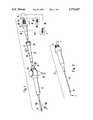
- FIG. 7is a cross-sectional view of still another alternate embodiment of the ultrasonic tissue resector as would be seen along the line 3--3 in FIG. 2.
- a hollow metal ultrasonic tissue resector for resecting tumors, cysts, and hematomas in the brain and spine of a patient and for resecting herniated spinal discsis shown, generally designated 10.
- the resector 10includes a hollow metal horn 12 and a distal tip 14, and the resector 10 is preferably slidably disposed in a working channel of a neuroendoscope 16.
- the distal tip 14 of the resector 10protrudes beyond the distal end of the neuroendoscope 16, while the proximal horn 12 of the resector 10 protrudes beyond the proximal end of the neuroendoscope 16.
- the resector 10is preferably radially supported in the neuroendoscope 16 by an appropriate fluid seal (not shown in FIG. 1), such as a fluid seal made by Touhy-Borst.
- the neuroendoscope 16is a neuroendoscope disclosed in U.S. Pat. No. 5,318,526 or a neuroendoscope disclosed in U.S. patent application Ser. No. 08/535,886, both of which are assigned to the same assignee to which the present invention is assigned, U.S. Pat. No. 5,318,526 incorporated herein by reference.
- the neuroendoscope 16includes a flexible hollow distal tube 16a which is biased to the straight configuration shown.
- a distal segment 16b of the tube 16acan be selectively moved to a curved configuration, shown in phantom in FIG. 1, by appropriately rotating a control wheel 16c of the neuroscope 16 which causes reciprocating motion of a hypotube-supported activating wire that is connected to the distal segment 16b.
- the resector 10includes a flexible distal segment that can assume the shape of the distal segment 16b of the neuroendoscope 16, as discussed below.
- a first source 22 of irrigating fluidis in fluid communication with the resector 10 via a first irrigating line 24.
- the irrigating line 24is connected to a Y-fitting 26 including a Touhy-Borst valve 28. Fluid from the source 22 of irrigating fluid can be directed through the working channel of the neuroendoscope 16 along the outside surface of the resector 10.
- a bundle 30 of image and illumination optical fibersextend through one of the lumens of the neuroendoscope 16 to illuminate the region beyond the distal end of the scope 16 and to transmit an image of the region to a viewing monitor (not shown), in accordance with endoscopic principles well-known in the art.
- fluid from a second fluid sourcecan be directed through a scope irrigation channel fitting 32 of the neuroendoscope 16.
- FIG. 1shows that the horn 12 of the resector 10 is externally threaded.
- an ultrasonic transducer 34is mounted in a housing 36, and the horn 12 of the resector 10 is threadably engageable with the housing 36, preferably to a torque of between fifteen inch-pounds to twenty inch-pounds (15 in.lbs.-20 in.lbs.) to couple the resector 10 with the transducer 34.
- the ultrasonic transducer 34is a piezoelectric crystal which is electrically connected to a source 38 of electrical current via an electrical line 40 as appropriate for energizing the transducer 34 to cause the transducer 34 to mechanically vibrate back-and-forth in the longitudinal dimension, i.e., in the dimension indicated by the arrows 42.
- the ultrasonic transducer 34vibrates with a frequency, preferably between about eighteen kiloHertz and forty kiloHertz (18 kHz-40 kHz), and the frequency defines a wavelength ⁇ .
- the frequency of vibrationis preferably above the audible range.
- the vibrationsare transmitted through a transmitting medium to the target tissue.
- a source “V” of vacuumis in fluid communication with the lumen of the resector 10 via a vacuum line “VL” and a vacuum fitting 43.
- the vacuum fitting 43is preferably formed as part of the housing 36, and is in fluid communication with and coaxial relative to the lumen of the resector 10.
- a vacuum lumenextends through the housing 36 to the vacuum line "VL”.
- fluid communication between the source "V” of vacuum and the lumen of the resector 10can be established via a vacuum line "VLL” (shown in phantom in FIG. 1) and through the horn 12.
- resected tissueBy appropriately evacuating the lumen of the resector 10, resected tissue can be removed from the patient endoscopically. Also, selected portions of the resector 10 can be cooled thereby, and the fluid pressure and temperature within the patient's skull can be maintained at a predetermined equilibrium value.
- the source "V" of vacuumis a peristaltic pump.
- the resector 10includes a hollow metal probe 44 extending distally away from the threaded horn 12.
- the probe 44is made of a material which optimizes transmission of ultrasonic energy through the probe 44, e.g., Aluminum, stainless steel, Titanium, Nitonol, or an alloy thereof.
- the probe 44includes a handle 46 which is distal to the horn 12 and which is formed integrally therewith or connected thereto by means well-known in the art.
- the handle 46tapers distally to a hollow cylindrical proximal transmitting element 48 which, together with the handle 46 and horn 12, establishes a proximal transmitting member.
- the proximal transmitting element 48defines an outside diameter OD 1 of about ninety four thousandths of an inch (0.094").
- the length L2 of the proximal transmitting element 48is equal to 1/2n* ⁇ , wherein n is a natural number. Consequently, the proximal transmitting element 48 is relatively rigid when made of the materials mentioned above.
- FIG. 3shows that a hollow cylindrical distal transmitting element 50 is attached to the proximal transmitting element 48 coaxial thereto. Together, the transmitting element 48, 50, handle 46, and horn 12 establish a transmitting member defining a central aspiration channel 52 and terminating in a distal end 54.
- the distal transmitting element 50is crimped or swaged to the proximal transmitting element 48 to a pull strength of about one hundred pounds (100#). Further, when the elements 48, 50 are made of materials that permit welding the elements 48, 50 together, they are welded together. Alternatively, the distal transmitting element 50 is soldered or brazed to the proximal transmitting element 48.
- One or both of the transmitting elements 48, 50can be made of Titanium or Nitonol, and when made of Nitonol, the elements 48, 50 are coated with Nickel prior to soldering to facilitate soldering.
- the distal transmitting element 50can be externally threaded, the proximal transmitting element can be internally threaded, and then the elements 48, 50 threadably engaged with each other.
- the distal transmitting element 50defines a length "LL" of about ten and thirty five hundredths inches (10.35”) and an outer diameter "ODD" of about one hundred sixty five thousandths of an inch (0.165").
- the distal transmitting element 50includes a flexible distal segment 56.
- the distal segment 56is rendered sufficiently flexible to conform to the neuroendoscope 16 by virtue of the distal segment 56 being formed with a plurality of, preferably seven, notches 58 that are longitudinally spaced from each other. As shown, each notch 58 extends radially around the distal segment 56, but not completely through the distal segment 56. Consequently, a longitudinally continuous strip 60 of the distal segment 56 is established.
- a smooth flexible plastic or Teflon® sheath 62 having a low coefficient of frictionis disposed around the distal segment 56, to prevent fluid communication through the notches 58. Thereby, evacuating the entire vacuum channel 52 of the probe 44 is facilitated.
- a distal hollow ultrasonic tip 64is coaxially joined to the distal segment 56 at the distal end 54 thereof by means well-known in the art.
- the ultrasonic tip 64is formed with a cylindrical outer surface 64a.
- the tip 64is formed with an inner surface 64b which includes a distal inner surface 66 that is longitudinally tapered inwardly toward a cylindrical proximal inner surface 68.
- the distal inner surface 66is longitudinally curved in accordance with wave focussing principles well-known in the art for focussing ultrasonic energy at a predetermined distance distal to the ultrasonic tip 64.
- the curvature of the distal inner surface 66can be concave.
- the curvature of the distal inner surface 66can be convex. In either case, it is to be understood that the curvature of the distal inner surface 66 is established as appropriate for focussing the ultrasonic energy transmitted by the probe 44 at a predetermined distance from the tip 64.
- the resector 10is slidably engaged with the working channel of the neuroendoscope 16 as shown in FIG. 1. Then, the neuroendoscope 16 is positioned through, e.g., an entry hole in the skull of a patient. Next, the distal segment of the neuroendoscope 16 is bent as desired to juxtapose the tip 14 of the resector 10 with tissue, e.g., a tumor, that is sought to be resected.
- tissuee.g., a tumor
- the ultrasonic transducer 30is energized to cause the transducer 30 to vibrate.
- the ultrasonic energyis transmitted through the ultrasonic probe of the present invention to ultrasonically excite the tip 14 and cause cavitation nearby the tissue, thereby breaking down the tissue.
- the source "V" of vacuumis activated to evacuate the aspiration channel 40 and remove broken down portions of tissue from the operating site.
- the operating sitecan be irrigated by directing irrigating fluid from the source 22 of irrigating fluid through the irrigation channel 56.
- the resector 10can be engaged with a lumen of a rigid elongated neuroendoscopic disposable sheath, generally designated 70.
- the sheath 70is a four-lumen rigid steel sheath made by Neuro Navigational Corp. of Costa Mesa, Calif.
- the sheath 70includes a rigid elongated probe 72 proximally coupled to a metal or plastic handpiece 74.
- a Y-fitting 76is threadably engaged with or bonded to the handpiece 74.
- the Y-fitting 76is a Touhy-Borst fitting that includes a hollow main branch 78 and a hollow ancillary branch 80.
- the main branch 78defines a main lumen 82 which joins the lumen of the ancillary branch 80, and the resector 10 is advanced through the main lumen 82.
- a source of irrigating fluidcan be connected to the ancillary lumen 80 to irrigate around the resector 10.
- an eyepiece lumen 84extends through the handpiece 74 and probe 72.
- the eyepiece lumen 84is parallel to and laterally offset from the axis 86 of the sheath 70.
- a rigid viewing scope 88 having an eyepiece 90is advanceable through the eyepiece lumen 84.
- the main branch 78(and, hence, a handpiece segment 82a of the main lumen 82 therein) establishes an angle ⁇ with respect to the axis 84 of the sheath 70.
- the angle ⁇is between about nine degrees and nineteen degrees (9°-19°), and more preferably is about fourteen degrees (14°).
- the main lumen 78is bent as shown within the handpiece 74 such that it extends through the probe 82 parallel to the axis 86 of the sheath 70.
- FIGS. 4B and 4Cshow that in addition to the main lumen 80 and eyepiece lumen 84, both of which extend through the probe 72 to the distal end thereof, additional lumens are formed in the sheath 70. More specifically, two opposed offset lumens 90, 92 are formed in the handpiece 74. In the handpiece 74, the offset lumens 90, 92 each establish an offset angle y with respect to the axis 86 of the sheath 70, to avoid interference between the components attached to the offset lumens 90, 92 and the other components attached to the sheath 70 described above. In the preferred embodiment, the offset angle ⁇ is equal to about fifteen degrees (15°).
- the offset lumens 90, 92are bent within the handpiece 74 such that they extend through the probe 82 parallel to the axis 86 of the sheath 70. Furthermore, a fifth lumen 94 can be established in the sheath 70, as best shown in FIG. 4B. It is to be understood that the offset and fifth lumens 90, 92, 94 can be used as irrigation lumens, evacuation lumens, working channel lumens, or fiber optic lumens as desired.
- an ultrasonic transducer 130can be operably engaged with an ultrasonic probe including a rigid primary ultrasonic taper 134 having a proximal end 134a that is mechanically coupled to the ultrasonic transducer 130 by means well-known in the art.
- the primary ultrasonic taper 134is a so-called horn having a distally tapered portion 134b, the contour of which is a taper such as is defined by a Gaussian or exponential function or linear taper, in accordance with principles well-known in the art.
- the primary ultrasonic taper 134amplifies longitudinal displacements, i.e., longitudinal vibrations, that are caused by the ultrasonic transducer 130 and transmits the displacements from the proximal end 134a of the primary taper 134 to a distal end 134c of the primary taper 134.
- the primary taper 134has an effective length LL1 that bears a predetermined relationship to the wavelength ⁇ .
- LL1is equal to 1/2n* ⁇ , wherein n is a natural number.
- LL1is equal to 0.25n* ⁇ , wherein n is an odd number.
- the above-described combination of structureensures that vibration amplitude loss is minimized by ensuring that junctions between components of the device shown are positioned at ultrasonic nodes.
- a rigid, tubular, hollow ultrasonic transmitting member 136has a proximal end segment 136a that is connected to the distal end 134c of the primary ultrasonic taper 134.
- the transmitting member 136is made of a material which optimizes transmission of ultrasonic energy through the member 136, e.g., Aluminum, Titanium, Nitonol, or an alloy thereof, and the member 136 defines an outside diameter OD 11 of about ninety four thousandths of an inch (0.094"), such that the transmitting member 136 is relatively rigid when made of the materials mentioned above.
- the length LL2 of the member 136is equal to 1/2n* ⁇ , wherein n is a natural number.
- the ultrasonic transmitting member 136is detachably coupled to the primary ultrasonic taper 134.
- the proximal end segment 136a of the ultrasonic transmitting member 136is threaded for detachably engaging a complementarily configured recess 138 which is formed in the primary ultrasonic taper 134.
- Alternative structuremay be used for detachably coupling the ultrasonic transmitting member 136 to the primary ultrasonic taper 134, e.g, a detent may be formed on one of the transmitting member 136 and primary ultrasonic taper 134, and a complementary cavity formed on the other component to receive the detent.
- the hollow transmitting member 136defines an aspiration channel 140. Further, a plug 142 is positioned in aspiration channel 140 in the proximal end segment 136a of the ultrasonic transmitting member 136 to block the aspiration channel 140.
- FIG. 5additionally shows that a flexible hollow catheter 144 surrounds and is closely spaced from the ultrasonic transmitting member 136.
- An aspiration port 146is formed in the ultrasonic transmitting member 136, and proximal and distal fluid seals 148, 150 are positioned between the catheter 144 and the ultrasonic transmitting member 136.
- the fluid seals 148, 150are resilient toroidal-shaped rubber or plastic o-rings which establish a ring-shaped aspiration plenum 152 between the catheter 144 and the ultrasonic transmitting member 136.
- the aspiration plenum 152communicates with a vacuum line 120 and, hence, with a source 118 of vacuum. Consequently, it may now be appreciated that the source 118 of vacuum can be activated to evacuate the aspiration channel 140.
- an irrigation port 154is formed in the catheter 144 distal to the distal fluid seal 150.
- An irrigation channel 156is established between the catheter 144 and the ultrasonic transmitting member 136 distal to the distal fluid seal 150, and the irrigation channel 156 communicates with a source of irrigating fluid via the irrigation port 154 and irrigating line 124.
- the irrigating fluidcools selected energized components, for example, the transmitting member 136, particularly where the transmitting member 136 might rub against, e.g., a bond in the neuroendoscope 16.
- the irrigating fluidcan be directed through the irrigating channel 156 to maintain intercranial pressure at a predetermined equilibrium value, ordinarily a value within normal physiological limits.
- the irrigating fluidestablishes a medium for ultrasonic vibration and the cavitation induced by the ultrasonic vibration.
- the ultrasonic transmitting member 136has a distal end 136b which terminates in a rigid hollow secondary ultrasonic taper 158.
- the secondary ultrasonic taper 158is a horn having a length LL3 equal to 1/2n* ⁇ , wherein n is a natural number.
- the secondary ultrasonic taper 158terminates at its distal end in a hollow tubular flexible joining member 160 having a length LL4 equal to 0.25n* ⁇ , wherein n is an odd integer.
- the ultrasonic transmitting member 136, secondary ultrasonic taper 158, and flexible joining member 160are formed integrally together, i.e., as a unitarily-formed structure.
- the ultrasonic components of the present inventioneach and collectively bear a predetermined relationship to the wavelength ⁇ .
- the flexible joining member 160is flexible owing to its small diameter, relative to the diameter of the transmitting member 136. More particularly, the inside diameter ID of the flexible joining member 160 is equal to about twenty thousandths of an inch (0.020"), and the outside diameter OD 21 , of the flexible joining member 160 is equal to about thirty thousandths of an inch (0.030").
- the joining member 160is relatively flexible compared to the transmitting member 136.
- relatively flexibleis meant that the flexible joining member 160 can assume the shape of the bendable distal segment of the neuroendoscope 16 shown in FIG. 1, when the neuroendoscope 16 is operated as disclosed in the above-referenced U.S. Patent and patent application.
- the flexible joining member 160can be established by a diametrically attenuated distal portion 158a of the secondary ultrasonic taper 158. This might be the case in applications wherein, because of the design of the secondary taper 158, its distal portion 158a is sufficiently long and flexible so as to allow the distal portion to assume the shape of the distal end of the neuroendoscope 16. Consequently, in such a case, the flexible joining member 160 is not a structure in addition to the secondary taper 158, but rather is established by the secondary taper 158.
- an ultrasonic probe intended for neurosurgeryneed not be flexible throughout its entire length, but only for the distal most segment of the probe. This is because neuroendoscopes (and accompanying surgical instruments, such as ultrasonic probes) are typically advanced only a few centimeters into a patient.
- a tip 114is included which is a rigid structure that is fixedly connected to the flexible joining member 160 for transmitting ultrasonic energy to tissue to break down the tissue. e.g., by cavitation or by direct impact, More particularly, the tip 114 is formed with a central channel 162, and the flexible joining member 160 is positioned in the central channel 162 and is bonded to the tip 114 to transmit ultrasonic energy to the tip 114. Together, the tip 114, flexible joining member 160, secondary taper 158, and transmitting member 136 establish an ultrasonic probe, and the ultrasonic probe of the present invention consequently includes a rigid proximal segment that is defined in part by the transmitting member 136 and a flexible distal segment that is defined by the flexible joining member 160.
- the central channel 162 of the tip 114communicates with the aspiration channel 140. Consequently, a source of vacuum can be activated to aspirate, through the central channel 162, tissue that is broken down by the tip 114. Stated differently, the aspiration channel 140 is juxtaposed with the tip 114 for evacuating portions of tissue broken down by the tip 114.
- a ring-shaped irrigation outlet port 164is formed in the tip 114.
- the irrigation outlet port 164communicates with the irrigation channel 156, such that fluid from a source of irrigating fluid can be flushed through the irrigation outlet port 164 to irrigate the surgery site.
- FIG. 6shows another alternate embodiment of the resector of the present invention, generally designated 270.
- the resector 270 shown in FIG. 6is in all essential respects identical in operation and construction to the resector shown in FIG. 5, with the following exceptions.
- the resector 270 shown in FIG. 6includes a solid ultrasonic probe 272 that includes a rigid transmitting member 274 and a flexible joining member 276, which can include a distally flexible taper 279.
- the joining member 276connects a tip 278 to the transmitting member 274 for transmitting ultrasonic energy from an ultrasonic transducer 280 to the tip 278.
- a multi-lumen catheter 282establishes an irrigation channel 284 and an aspiration channel 286, and the tip 278 is formed with an irrigation outlet port 288 and an aspiration inlet port 290 that respectively communicate with the channels 284, 286.
- the lumens of the catheter 282are concentric, but it is to be understood that the lumens may extend through the catheter longitudinally side-by-side, instead of concentrically.
- FIG. 7shows yet another embodiment of the resector of the present invention, generally designated 300.
- the resector 300includes a rigid metal, preferably aluminum or titanium alloy ultrasonic horn 302 that is formed with an externally threaded proximal segment 304 defining a lip 305.
- the proximal segment 304threadably engages the housing 36 (FIG. 1), and is preferably tightened in the housing 36 to a torque of between fifteen inch-pounds to twenty inch-pounds (15 in.lbs.-20 in.lbs.).
- the horn 302preferably is a high gain, so-called "step" horn.
- the horn 12is formed with a radially enlarged portion 306 that tapers distally to a radially smaller portion 308, for amplifying the transmission of ultrasonic energy therealong.
- the probe 300defines a vacuum channel 310 that includes a radially expanded portion 312 in the radially enlarged portion 306 of the horn 302.
- FIG. 7shows that the radially smaller portion 308 of the horn 302 is formed with an annular abutment surface 312.
- the distance "S" between the lip 305 and the abutment surface 312is one-quarter of a wavelength of the ultrasonic energy.
- the radially smaller portion 308 of the horn 302is internally threaded as shown.
- An annular hub surface 314circumscribes the vacuum channel 310 distal to the internally threaded portion of the horn 302.
- a hollow titanium hub 316holds a hollow elongated titanium probe 318 tightly against the horn 302 in a mutually coaxial relationship therewith.
- the hub 316is formed with external threads 320 that engage the internally threaded portion of the horn 302.
- the probe 318is formed with a proximal disc-shaped collar 322, and the collar 322 is held in tight compression between the abutment surface 312 of the horn 302 and a proximal end 324 of the hub 316.
- the hub 316is tightened in the horn 302 to a torque of between three inch-pounds and six inch-pounds (3 in.-lbs.-6 in.-lbs.)
- the hub 316Distal to its threads 320, the hub 316 is formed with an annular seating flange 326. As shown, the seating flange 326 is configured for abutting the hub surface 314 and for being closely received in the cavity established by the hub surface 314. Per the embodiment shown in FIG. 7, the outer surface of the hub 316 tapers distally inwardly from the seating flange 326 to the probe 318.
- the probe 318defines a distal tip 328 and a transverse axis 330.
- the distal tip 328is cleaved in that it establishes an oblique angle ⁇ , preferably ten degrees to fifteen degrees (10°-15°), with respect to the transverse axis 330, for maintaining a constant vacuum on tissue distal to the tip 328 and for promoting the transmission of energy toward tissue distal to the tip 328.
- the distance "SS" between the lip 305 of the horn 302 and the distal tip 328 of the probe 318is an integer multiple of one-half the wavelength of the ultrasonic energy being transmitted.
- a hollow proximal segment 332 of the probe 318extends distally away from the collar 322.
- the proximal segment 332defines an inside diameter 334 of about fifty three thousandths of an inch (0.053") and an outside diameter 336 of about one thousand fifty eight ten thousandths of an inch (0.1058").
- FIG. 7shows that the proximal segment 332 of the probe 318 terminates in a distally tapered segment 338.
- the taper angle ⁇ of the tapered segment 338is about six degrees (6°) relative to the long axis 339 of the probe 318.
- the tapered segment 338terminates in a distally intermediate segment 340 having an outside diameter 342 of about ninety three thousandths of an inch (0.093").
- the probe 318is stepped in that the distally intermediate segment 340 abruptly steps to a distal segment 344 having an outside diameter 346 of about eighty thousandths of an inch (0.080").
- the distal segment 344terminates in a tip segment 348.
- the wall of the tip segment 348is swaged inwardly, such that both the inside and outside diameters of the tip segment 348 taper radially inwardly toward the distal tip 328.
- the taper angle ⁇ of the tip segment 348is between three degrees and ten degrees (3°-10°) relative to the long axis of the probe 318.
- the tip segment 348has an inwardly tapering inside diameter
- the inside diameters of all four segments 332, 338, 340, and 344are constant and are equal to each other. Stated differently, all four segments 332, 338, 340, and 344 have the same inside diameter. Accordingly, it may now be appreciated that the probe 318 is made from a unitary tube, with the segments 332, 338, 340, and 344 of the probe 318 being established by machining the outer surface of the tube as appropriate. It is further to be appreciated that the lengths of the segments 332, 338, 340, and 344 are established per principles discussed above to optimize the transmission of ultrasonic energy through the probe 318.
- the tapers and steps of the probe 318 disclosed aboveamplify ultrasonic energy. And, the above-described combination of structure ensures that vibration amplitude loss is minimized by ensuring that junctions between components of the device shown are positioned at ultrasonic nodes.
Landscapes
- Health & Medical Sciences (AREA)
- Surgery (AREA)
- Engineering & Computer Science (AREA)
- Life Sciences & Earth Sciences (AREA)
- Heart & Thoracic Surgery (AREA)
- Nuclear Medicine, Radiotherapy & Molecular Imaging (AREA)
- Mechanical Engineering (AREA)
- Biomedical Technology (AREA)
- Dentistry (AREA)
- Medical Informatics (AREA)
- Molecular Biology (AREA)
- Animal Behavior & Ethology (AREA)
- General Health & Medical Sciences (AREA)
- Public Health (AREA)
- Veterinary Medicine (AREA)
- Surgical Instruments (AREA)
Abstract
Description
Claims (8)
Priority Applications (3)
| Application Number | Priority Date | Filing Date | Title |
|---|---|---|---|
| US08/684,425US5772627A (en) | 1996-07-19 | 1996-07-19 | Ultrasonic tissue resector for neurosurgery |
| AU40427/97AAU4042797A (en) | 1996-07-19 | 1997-07-19 | Ultrasonic tissue resector for neurosurgery |
| PCT/US1997/012696WO1998003111A2 (en) | 1996-07-19 | 1997-07-19 | Ultrasonic tissue resector for neurosurgery |
Applications Claiming Priority (1)
| Application Number | Priority Date | Filing Date | Title |
|---|---|---|---|
| US08/684,425US5772627A (en) | 1996-07-19 | 1996-07-19 | Ultrasonic tissue resector for neurosurgery |
Publications (1)
| Publication Number | Publication Date |
|---|---|
| US5772627Atrue US5772627A (en) | 1998-06-30 |
Family
ID=24748012
Family Applications (1)
| Application Number | Title | Priority Date | Filing Date |
|---|---|---|---|
| US08/684,425Expired - Fee RelatedUS5772627A (en) | 1996-07-19 | 1996-07-19 | Ultrasonic tissue resector for neurosurgery |
Country Status (3)
| Country | Link |
|---|---|
| US (1) | US5772627A (en) |
| AU (1) | AU4042797A (en) |
| WO (1) | WO1998003111A2 (en) |
Cited By (75)
| Publication number | Priority date | Publication date | Assignee | Title |
|---|---|---|---|---|
| USD409308S (en)* | 1998-01-23 | 1999-05-04 | Transonic Systems, Inc. | Ultrasonic probe |
| US5976105A (en)* | 1997-03-05 | 1999-11-02 | Marcove; Ralph C. | Intra annular ultrasound disc apparatus and method |
| WO2000001310A1 (en)* | 1998-07-02 | 2000-01-13 | Fibrasonics Inc. | Ultrasonic probe with isolated and teflon coated outer cannula |
| US6045532A (en)* | 1998-02-20 | 2000-04-04 | Arthrocare Corporation | Systems and methods for electrosurgical treatment of tissue in the brain and spinal cord |
| US6214017B1 (en)* | 1998-09-25 | 2001-04-10 | Sherwood Services Ag | Ultrasonic surgical apparatus |
| US6270471B1 (en)* | 1997-12-23 | 2001-08-07 | Misonix Incorporated | Ultrasonic probe with isolated outer cannula |
| US6454782B1 (en) | 1998-04-13 | 2002-09-24 | Ethicon Endo-Surgery, Inc. | Actuation mechanism for surgical instruments |
| US20030065263A1 (en)* | 1999-10-05 | 2003-04-03 | Omnisonics Medical Technologies, Inc. | Ultrasonic probe device with rapid attachment and detachment means having a line contact collet |
| US6551337B1 (en) | 1999-10-05 | 2003-04-22 | Omnisonics Medical Technologies, Inc. | Ultrasonic medical device operating in a transverse mode |
| US20030083683A1 (en)* | 1998-04-13 | 2003-05-01 | Schwemberger Richard F. | Articulating ultrasonic surgical shears |
| US6632230B2 (en)* | 2001-04-12 | 2003-10-14 | Scimed Life Systems, Inc. | Ablation system with catheter clearing abrasive |
| US20030216760A1 (en)* | 2002-05-20 | 2003-11-20 | Eric Welch | Apparatus and system for removing an obstruction from a lumen |
| US6660013B2 (en) | 1999-10-05 | 2003-12-09 | Omnisonics Medical Technologies, Inc. | Apparatus for removing plaque from blood vessels using ultrasonic energy |
| US20030236539A1 (en)* | 1999-10-05 | 2003-12-25 | Omnisonics Medical Technologies, Inc. | Apparatus and method for using an ultrasonic probe to clear a vascular access device |
| US6695782B2 (en) | 1999-10-05 | 2004-02-24 | Omnisonics Medical Technologies, Inc. | Ultrasonic probe device with rapid attachment and detachment means |
| US20040059254A1 (en)* | 2001-03-23 | 2004-03-25 | Stryker Puerto Rico Limited | Micro-invasive breast biopsy device |
| US6733451B2 (en) | 1999-10-05 | 2004-05-11 | Omnisonics Medical Technologies, Inc. | Apparatus and method for an ultrasonic probe used with a pharmacological agent |
| US20040097996A1 (en)* | 1999-10-05 | 2004-05-20 | Omnisonics Medical Technologies, Inc. | Apparatus and method of removing occlusions using an ultrasonic medical device operating in a transverse mode |
| US20040249401A1 (en)* | 1999-10-05 | 2004-12-09 | Omnisonics Medical Technologies, Inc. | Apparatus and method for an ultrasonic medical device with a non-compliant balloon |
| US20050043629A1 (en)* | 1999-10-05 | 2005-02-24 | Omnisonics Medical Technologies, Inc. | Apparatus and method for an ultrasonic medical device having a probe with a small proximal end |
| US20050043753A1 (en)* | 1999-10-05 | 2005-02-24 | Omnisonics Medical Technologies, Inc. | Apparatus and method for an ultrasonic medical device to treat peripheral artery disease |
| US20050096669A1 (en)* | 1999-10-05 | 2005-05-05 | Omnisonics Medical Technologies, Inc. | Apparatus and method for an ultrasonic medical device to treat coronary thrombus bearing lesions |
| US20050119679A1 (en)* | 1999-10-05 | 2005-06-02 | Omnisonics Medical Technologies, Inc. | Apparatus and method for an ultrasonic medical device to treat chronic total occlusions |
| US20050209530A1 (en)* | 2001-03-23 | 2005-09-22 | Stryker Puerto Rico Limited | Micro-invasive tissue removal device |
| US20050222593A1 (en)* | 2004-03-19 | 2005-10-06 | Medical Components, Inc | Magnet cuff for vascular catheters and bloodlines |
| WO2006041475A1 (en)* | 2004-10-06 | 2006-04-20 | Omnisonics Medical Technologies, Inc. | Apparatus and method for an ultrasonic medical device having a probe with a small proximal end |
| US20060241566A1 (en)* | 2005-04-11 | 2006-10-26 | Orthox, Llc | Nucleus Extraction from Spine Intervertebral Disc |
| US20070131034A1 (en)* | 2005-12-12 | 2007-06-14 | Kimberly-Clark Worldwide, Inc. | Amplifying ultrasonic waveguides |
| US20070130771A1 (en)* | 2005-12-12 | 2007-06-14 | Kimberly-Clark Worldwide, Inc. | Methods for producing ultrasonic waveguides having improved amplification |
| US20070162007A1 (en)* | 2004-08-13 | 2007-07-12 | Mazor Surgical Technologies, Ltd. | Minimally invasive spinal fusion |
| US20070255172A1 (en)* | 2001-03-23 | 2007-11-01 | Stryker Puerto Rico Limited | Micro-invasive nucleotomy device and method |
| US20070255268A1 (en)* | 2006-04-28 | 2007-11-01 | Nobis Rudolph H | Method for performing an endoscopic mucosal resection |
| US20070255196A1 (en)* | 2006-04-19 | 2007-11-01 | Wuchinich David G | Ultrasonic liquefaction method and apparatus using a tapered ultrasonic tip |
| US20070255278A1 (en)* | 2006-04-28 | 2007-11-01 | Nobis Rudolph H | Apparatus and method for deploying a cutting element during an endoscopic mucosal resection |
| US20070255277A1 (en)* | 2006-04-28 | 2007-11-01 | Nobis Rudolph H | Apparatus and method for performing an endoscopic mucosal resection |
| US20070265633A1 (en)* | 2006-05-11 | 2007-11-15 | Moon Jon K | Implement and method to extract nucleus from spine intervertebral disc |
| US20080051708A1 (en)* | 2006-08-24 | 2008-02-28 | Alka Kumar | Surgical aspiration system and method of surgical aspiration |
| US20080154181A1 (en)* | 2006-05-05 | 2008-06-26 | Khanna Rohit K | Central nervous system ultrasonic drain |
| US7503895B2 (en) | 1999-10-05 | 2009-03-17 | Omnisonics Medical Technologies, Inc. | Ultrasonic device for tissue ablation and sheath for use therewith |
| US7505807B1 (en) | 1997-05-15 | 2009-03-17 | Regents Of The University Of Minnesota | Magnetic resonance apparatus for use with active electrode and drug deliver catheter |
| US20100107887A1 (en)* | 2007-02-27 | 2010-05-06 | Kraft Foods R & D, Inc. | Machine For The Preparation Of Beverages |
| US20100152762A1 (en)* | 2008-12-16 | 2010-06-17 | Mark Joseph L | Tissue removal system with multi-directional foot actuator assembly for neurosurgical and spinal surgery applications |
| US20100152614A1 (en)* | 2008-12-16 | 2010-06-17 | Mark Joseph L | Tissue removal device for neurosurgical and spinal surgery applications |
| US20100152761A1 (en)* | 2008-12-16 | 2010-06-17 | Mark Joseph L | Tissue removal device for neurosurgical and spinal surgery applications |
| US20100152615A1 (en)* | 2008-12-16 | 2010-06-17 | Mark Joseph L | Tissue removal device with adjustable fluid supply sleeve for neurosurgical and spinal surgery applications |
| US20100152760A1 (en)* | 2008-12-16 | 2010-06-17 | Mark Joseph L | Tissue removal device for neurosurgical and spinal surgery applications |
| US20100152756A1 (en)* | 2008-12-16 | 2010-06-17 | Mark Joseph L | Tissue removal device for neurosurgical and spinal surgery applications |
| US20100152758A1 (en)* | 2008-12-16 | 2010-06-17 | Mark Joseph L | Tissue removal device for neurosurgical and spinal surgery applications |
| US20100152533A1 (en)* | 2008-12-16 | 2010-06-17 | Mark Joseph L | Tissue removal device for use with imaging devices in neurosurgical and spinal surgery applications |
| US7794414B2 (en) | 2004-02-09 | 2010-09-14 | Emigrant Bank, N.A. | Apparatus and method for an ultrasonic medical device operating in torsional and transverse modes |
| US20100249817A1 (en)* | 2008-12-16 | 2010-09-30 | Mark Joseph L | Positioning system for tissue removal device |
| US20120253351A1 (en)* | 2003-09-11 | 2012-10-04 | Duran Yetkinler | Use of Vibration with Orthopedic Cements |
| US20150005775A1 (en)* | 2013-06-28 | 2015-01-01 | Misonix Incorporated | Ultrasonic cutting blade with cooling liquid conduction |
| WO2015014650A1 (en)* | 2013-07-30 | 2015-02-05 | Söring GmbH | Sonotrode |
| US9044568B2 (en) | 2007-06-22 | 2015-06-02 | Ekos Corporation | Method and apparatus for treatment of intracranial hemorrhages |
| US9279751B2 (en) | 2008-12-16 | 2016-03-08 | Nico Corporation | System and method of taking and collecting tissue cores for treatment |
| US9504247B2 (en) | 2008-12-16 | 2016-11-29 | Nico Corporation | System for collecting and preserving tissue cores |
| WO2017025069A1 (en)* | 2015-08-07 | 2017-02-16 | Weber Ultrasonics Gmbh | Device for deburring work pieces by means of ultrasound |
| US9579494B2 (en) | 2013-03-14 | 2017-02-28 | Ekos Corporation | Method and apparatus for drug delivery to a target site |
| US9615969B2 (en) | 2012-12-18 | 2017-04-11 | Novartis Ag | Multi-port vitrectomy probe with dual cutting edges |
| US9693898B2 (en) | 2014-11-19 | 2017-07-04 | Novartis Ag | Double-acting vitreous probe with contoured port |
| US9707024B2 (en) | 2004-03-09 | 2017-07-18 | Skeletal Kinetics, Llc | Use of vibration in composite fixation |
| WO2017189312A1 (en)* | 2016-04-29 | 2017-11-02 | Bausch & Lomb Incorporated | Ultrasonic surgical aspiration needle assembly with molded hub |
| US9820480B2 (en) | 2008-12-16 | 2017-11-21 | Nico Corporation | System for collecting and preserving tissue cores |
| US20180000505A1 (en)* | 2015-04-22 | 2018-01-04 | Olympus Corporation | Treatment device and treatment system |
| US9931105B2 (en) | 2008-12-16 | 2018-04-03 | Nico Corporation | System and method of taking and collecting tissue cores for treatment |
| US10080578B2 (en) | 2008-12-16 | 2018-09-25 | Nico Corporation | Tissue removal device with adjustable delivery sleeve for neurosurgical and spinal surgery applications |
| US10368890B2 (en) | 2008-12-16 | 2019-08-06 | Nico Corporation | Multi-functional surgical device for neurosurgical and spinal surgery applications |
| WO2019152898A1 (en) | 2018-02-03 | 2019-08-08 | Caze Technologies | Surgical systems with sensing and machine learning capabilities and methods thereof |
| US10656025B2 (en) | 2015-06-10 | 2020-05-19 | Ekos Corporation | Ultrasound catheter |
| US10702336B2 (en) | 2005-09-02 | 2020-07-07 | Madison Surgical Designs, Llc | Surgical devices |
| US10888657B2 (en) | 2010-08-27 | 2021-01-12 | Ekos Corporation | Method and apparatus for treatment of intracranial hemorrhages |
| US10926074B2 (en) | 2001-12-03 | 2021-02-23 | Ekos Corporation | Catheter with multiple ultrasound radiating members |
| US11166845B2 (en) | 2018-04-03 | 2021-11-09 | Alcon Inc. | Ultrasonic vitreous cutting tip |
| US11925367B2 (en) | 2007-01-08 | 2024-03-12 | Ekos Corporation | Power parameters for ultrasonic catheter |
Families Citing this family (2)
| Publication number | Priority date | Publication date | Assignee | Title |
|---|---|---|---|---|
| DE102007001123B8 (en)* | 2007-01-04 | 2008-10-16 | Andreas Koepcke | ultrasonic dissector |
| US9408624B2 (en) | 2011-03-31 | 2016-08-09 | Isis Innovation Limited | Intervertebral disc treatment apparatus |
Citations (8)
| Publication number | Priority date | Publication date | Assignee | Title |
|---|---|---|---|---|
| US4869715A (en)* | 1988-04-21 | 1989-09-26 | Sherburne Fred S | Ultrasonic cone and method of construction |
| US4923441A (en)* | 1989-02-23 | 1990-05-08 | Concept, Inc. | Surgical cutting instrument with titanium nitride coating on an inner tubular member |
| US5061238A (en)* | 1989-02-23 | 1991-10-29 | Linvatec Corporation | Surgical cutting instrument with titanium nitride coating on an inner tubular member |
| US5318526A (en)* | 1992-09-29 | 1994-06-07 | Neuro Navigational Corporation | Flexible endoscope with hypotube activating wire support |
| US5324255A (en)* | 1991-01-11 | 1994-06-28 | Baxter International Inc. | Angioplasty and ablative devices having onboard ultrasound components and devices and methods for utilizing ultrasound to treat or prevent vasopasm |
| US5324297A (en)* | 1989-01-31 | 1994-06-28 | Advanced Osseous Technologies, Inc. | Ultrasonic tool connector |
| US5359996A (en)* | 1988-10-21 | 1994-11-01 | Nestle, S.A. | Ultrasonic cutting tip and assembly |
| US5382228A (en)* | 1992-07-09 | 1995-01-17 | Baxter International Inc. | Method and device for connecting ultrasound transmission member (S) to an ultrasound generating device |
- 1996
- 1996-07-19USUS08/684,425patent/US5772627A/ennot_activeExpired - Fee Related
- 1997
- 1997-07-19AUAU40427/97Apatent/AU4042797A/ennot_activeAbandoned
- 1997-07-19WOPCT/US1997/012696patent/WO1998003111A2/enunknown
Patent Citations (8)
| Publication number | Priority date | Publication date | Assignee | Title |
|---|---|---|---|---|
| US4869715A (en)* | 1988-04-21 | 1989-09-26 | Sherburne Fred S | Ultrasonic cone and method of construction |
| US5359996A (en)* | 1988-10-21 | 1994-11-01 | Nestle, S.A. | Ultrasonic cutting tip and assembly |
| US5324297A (en)* | 1989-01-31 | 1994-06-28 | Advanced Osseous Technologies, Inc. | Ultrasonic tool connector |
| US4923441A (en)* | 1989-02-23 | 1990-05-08 | Concept, Inc. | Surgical cutting instrument with titanium nitride coating on an inner tubular member |
| US5061238A (en)* | 1989-02-23 | 1991-10-29 | Linvatec Corporation | Surgical cutting instrument with titanium nitride coating on an inner tubular member |
| US5324255A (en)* | 1991-01-11 | 1994-06-28 | Baxter International Inc. | Angioplasty and ablative devices having onboard ultrasound components and devices and methods for utilizing ultrasound to treat or prevent vasopasm |
| US5382228A (en)* | 1992-07-09 | 1995-01-17 | Baxter International Inc. | Method and device for connecting ultrasound transmission member (S) to an ultrasound generating device |
| US5318526A (en)* | 1992-09-29 | 1994-06-07 | Neuro Navigational Corporation | Flexible endoscope with hypotube activating wire support |
Cited By (119)
| Publication number | Priority date | Publication date | Assignee | Title |
|---|---|---|---|---|
| US5976105A (en)* | 1997-03-05 | 1999-11-02 | Marcove; Ralph C. | Intra annular ultrasound disc apparatus and method |
| US7505807B1 (en) | 1997-05-15 | 2009-03-17 | Regents Of The University Of Minnesota | Magnetic resonance apparatus for use with active electrode and drug deliver catheter |
| US6270471B1 (en)* | 1997-12-23 | 2001-08-07 | Misonix Incorporated | Ultrasonic probe with isolated outer cannula |
| USD409308S (en)* | 1998-01-23 | 1999-05-04 | Transonic Systems, Inc. | Ultrasonic probe |
| US6045532A (en)* | 1998-02-20 | 2000-04-04 | Arthrocare Corporation | Systems and methods for electrosurgical treatment of tissue in the brain and spinal cord |
| US6322549B1 (en) | 1998-02-20 | 2001-11-27 | Arthocare Corporation | Systems and methods for electrosurgical treatment of tissue in the brain and spinal cord |
| US6454782B1 (en) | 1998-04-13 | 2002-09-24 | Ethicon Endo-Surgery, Inc. | Actuation mechanism for surgical instruments |
| US7135030B2 (en) | 1998-04-13 | 2006-11-14 | Ethicon Endo-Surgery, Inc. | Articulating ultrasonic surgical shears |
| US20030083683A1 (en)* | 1998-04-13 | 2003-05-01 | Schwemberger Richard F. | Articulating ultrasonic surgical shears |
| WO2000001310A1 (en)* | 1998-07-02 | 2000-01-13 | Fibrasonics Inc. | Ultrasonic probe with isolated and teflon coated outer cannula |
| US6214017B1 (en)* | 1998-09-25 | 2001-04-10 | Sherwood Services Ag | Ultrasonic surgical apparatus |
| US6589200B1 (en) | 1999-02-22 | 2003-07-08 | Ethicon Endo-Surgery, Inc. | Articulating ultrasonic surgical shears |
| US6866670B2 (en) | 1999-10-05 | 2005-03-15 | Omnisonics Medical Technologies, Inc. | Apparatus for removing plaque from blood vessels using ultrasonic energy |
| US20050096669A1 (en)* | 1999-10-05 | 2005-05-05 | Omnisonics Medical Technologies, Inc. | Apparatus and method for an ultrasonic medical device to treat coronary thrombus bearing lesions |
| US20030125645A1 (en)* | 1999-10-05 | 2003-07-03 | Omnisonics Medical Technologies, Inc. | Ultrasonic medical device operating in a transverse mode |
| US6660013B2 (en) | 1999-10-05 | 2003-12-09 | Omnisonics Medical Technologies, Inc. | Apparatus for removing plaque from blood vessels using ultrasonic energy |
| US20030236539A1 (en)* | 1999-10-05 | 2003-12-25 | Omnisonics Medical Technologies, Inc. | Apparatus and method for using an ultrasonic probe to clear a vascular access device |
| US6695782B2 (en) | 1999-10-05 | 2004-02-24 | Omnisonics Medical Technologies, Inc. | Ultrasonic probe device with rapid attachment and detachment means |
| US20030065263A1 (en)* | 1999-10-05 | 2003-04-03 | Omnisonics Medical Technologies, Inc. | Ultrasonic probe device with rapid attachment and detachment means having a line contact collet |
| US20040073244A1 (en)* | 1999-10-05 | 2004-04-15 | Omnisonics Medical Technologies, Inc. | Method and apparatus for removing plaque from blood vessels using ultrasonic energy |
| US6733451B2 (en) | 1999-10-05 | 2004-05-11 | Omnisonics Medical Technologies, Inc. | Apparatus and method for an ultrasonic probe used with a pharmacological agent |
| US20040097996A1 (en)* | 1999-10-05 | 2004-05-20 | Omnisonics Medical Technologies, Inc. | Apparatus and method of removing occlusions using an ultrasonic medical device operating in a transverse mode |
| US20040158151A1 (en)* | 1999-10-05 | 2004-08-12 | Omnisonics Medical Technologies, Inc. | Apparatus and method for an ultrasonic probe device with rapid attachment and detachment means |
| US20040162571A1 (en)* | 1999-10-05 | 2004-08-19 | Omnisonics Medical Technologies, Inc. | Apparatus and method for an ultrasonic medical device to treat deep vein thrombosis |
| US20040249401A1 (en)* | 1999-10-05 | 2004-12-09 | Omnisonics Medical Technologies, Inc. | Apparatus and method for an ultrasonic medical device with a non-compliant balloon |
| US20050043629A1 (en)* | 1999-10-05 | 2005-02-24 | Omnisonics Medical Technologies, Inc. | Apparatus and method for an ultrasonic medical device having a probe with a small proximal end |
| US20050043753A1 (en)* | 1999-10-05 | 2005-02-24 | Omnisonics Medical Technologies, Inc. | Apparatus and method for an ultrasonic medical device to treat peripheral artery disease |
| US8790359B2 (en) | 1999-10-05 | 2014-07-29 | Cybersonics, Inc. | Medical systems and related methods |
| US6551337B1 (en) | 1999-10-05 | 2003-04-22 | Omnisonics Medical Technologies, Inc. | Ultrasonic medical device operating in a transverse mode |
| US20050119679A1 (en)* | 1999-10-05 | 2005-06-02 | Omnisonics Medical Technologies, Inc. | Apparatus and method for an ultrasonic medical device to treat chronic total occlusions |
| US7494468B2 (en) | 1999-10-05 | 2009-02-24 | Omnisonics Medical Technologies, Inc. | Ultrasonic medical device operating in a transverse mode |
| US7503895B2 (en) | 1999-10-05 | 2009-03-17 | Omnisonics Medical Technologies, Inc. | Ultrasonic device for tissue ablation and sheath for use therewith |
| US20050209530A1 (en)* | 2001-03-23 | 2005-09-22 | Stryker Puerto Rico Limited | Micro-invasive tissue removal device |
| US7591790B2 (en) | 2001-03-23 | 2009-09-22 | Stryker Puerto Rico Limited | Micro-invasive device |
| US20040059254A1 (en)* | 2001-03-23 | 2004-03-25 | Stryker Puerto Rico Limited | Micro-invasive breast biopsy device |
| US20070255172A1 (en)* | 2001-03-23 | 2007-11-01 | Stryker Puerto Rico Limited | Micro-invasive nucleotomy device and method |
| US6632230B2 (en)* | 2001-04-12 | 2003-10-14 | Scimed Life Systems, Inc. | Ablation system with catheter clearing abrasive |
| US10926074B2 (en) | 2001-12-03 | 2021-02-23 | Ekos Corporation | Catheter with multiple ultrasound radiating members |
| US7179269B2 (en) | 2002-05-20 | 2007-02-20 | Scimed Life Systems, Inc. | Apparatus and system for removing an obstruction from a lumen |
| US20030216760A1 (en)* | 2002-05-20 | 2003-11-20 | Eric Welch | Apparatus and system for removing an obstruction from a lumen |
| US9833274B2 (en)* | 2003-09-11 | 2017-12-05 | Skeletal Kinetics, Llc | Use of vibration with orthopedic cements |
| US20120253351A1 (en)* | 2003-09-11 | 2012-10-04 | Duran Yetkinler | Use of Vibration with Orthopedic Cements |
| US7794414B2 (en) | 2004-02-09 | 2010-09-14 | Emigrant Bank, N.A. | Apparatus and method for an ultrasonic medical device operating in torsional and transverse modes |
| US9707024B2 (en) | 2004-03-09 | 2017-07-18 | Skeletal Kinetics, Llc | Use of vibration in composite fixation |
| US8197465B2 (en)* | 2004-03-19 | 2012-06-12 | Medical Components, Inc. | Magnet cuff for vascular catheters and bloodlines |
| US20050222593A1 (en)* | 2004-03-19 | 2005-10-06 | Medical Components, Inc | Magnet cuff for vascular catheters and bloodlines |
| US9655649B2 (en)* | 2004-08-13 | 2017-05-23 | Mazor Robotics Ltd. | Spinal fusion using rods of shape memory material |
| US20070162007A1 (en)* | 2004-08-13 | 2007-07-12 | Mazor Surgical Technologies, Ltd. | Minimally invasive spinal fusion |
| WO2006041475A1 (en)* | 2004-10-06 | 2006-04-20 | Omnisonics Medical Technologies, Inc. | Apparatus and method for an ultrasonic medical device having a probe with a small proximal end |
| US20060241566A1 (en)* | 2005-04-11 | 2006-10-26 | Orthox, Llc | Nucleus Extraction from Spine Intervertebral Disc |
| US10702336B2 (en) | 2005-09-02 | 2020-07-07 | Madison Surgical Designs, Llc | Surgical devices |
| US11259865B2 (en) | 2005-09-02 | 2022-03-01 | Madison Surgical Designs, Llc | Surgical methods |
| US20070131034A1 (en)* | 2005-12-12 | 2007-06-14 | Kimberly-Clark Worldwide, Inc. | Amplifying ultrasonic waveguides |
| US8459122B2 (en)* | 2005-12-12 | 2013-06-11 | Kimberly-Clark Worldwide, Inc. | Amplifying ultrasonic waveguides |
| US20070130771A1 (en)* | 2005-12-12 | 2007-06-14 | Kimberly-Clark Worldwide, Inc. | Methods for producing ultrasonic waveguides having improved amplification |
| US8033173B2 (en)* | 2005-12-12 | 2011-10-11 | Kimberly-Clark Worldwide, Inc. | Amplifying ultrasonic waveguides |
| US20070255196A1 (en)* | 2006-04-19 | 2007-11-01 | Wuchinich David G | Ultrasonic liquefaction method and apparatus using a tapered ultrasonic tip |
| US20070255278A1 (en)* | 2006-04-28 | 2007-11-01 | Nobis Rudolph H | Apparatus and method for deploying a cutting element during an endoscopic mucosal resection |
| US20070255277A1 (en)* | 2006-04-28 | 2007-11-01 | Nobis Rudolph H | Apparatus and method for performing an endoscopic mucosal resection |
| US7867228B2 (en) | 2006-04-28 | 2011-01-11 | Ethicon Endo-Surgery, Inc. | Apparatus and method for performing an endoscopic mucosal resection |
| US7651491B2 (en) | 2006-04-28 | 2010-01-26 | Ethicon Endo-Surgery, Inc. | Method for performing an endoscopic mucosal resection |
| US20070255268A1 (en)* | 2006-04-28 | 2007-11-01 | Nobis Rudolph H | Method for performing an endoscopic mucosal resection |
| US20120265123A1 (en)* | 2006-05-05 | 2012-10-18 | Neurovention, Llc. | Central Nervous System Drain |
| US20080154181A1 (en)* | 2006-05-05 | 2008-06-26 | Khanna Rohit K | Central nervous system ultrasonic drain |
| US20120271223A1 (en)* | 2006-05-05 | 2012-10-25 | Neurovention, LLC | Central Nervous System Drain |
| US20070265633A1 (en)* | 2006-05-11 | 2007-11-15 | Moon Jon K | Implement and method to extract nucleus from spine intervertebral disc |
| US20080051708A1 (en)* | 2006-08-24 | 2008-02-28 | Alka Kumar | Surgical aspiration system and method of surgical aspiration |
| US7918822B2 (en)* | 2006-08-24 | 2011-04-05 | Alka Kumar | Surgical aspiration system and method of surgical aspiration |
| US11925367B2 (en) | 2007-01-08 | 2024-03-12 | Ekos Corporation | Power parameters for ultrasonic catheter |
| US20100107887A1 (en)* | 2007-02-27 | 2010-05-06 | Kraft Foods R & D, Inc. | Machine For The Preparation Of Beverages |
| US9044568B2 (en) | 2007-06-22 | 2015-06-02 | Ekos Corporation | Method and apparatus for treatment of intracranial hemorrhages |
| US11672553B2 (en) | 2007-06-22 | 2023-06-13 | Ekos Corporation | Method and apparatus for treatment of intracranial hemorrhages |
| US20100152756A1 (en)* | 2008-12-16 | 2010-06-17 | Mark Joseph L | Tissue removal device for neurosurgical and spinal surgery applications |
| US20100152760A1 (en)* | 2008-12-16 | 2010-06-17 | Mark Joseph L | Tissue removal device for neurosurgical and spinal surgery applications |
| US8496599B2 (en) | 2008-12-16 | 2013-07-30 | Nico Corporation | Tissue removal device for neurosurgical and spinal surgery applications |
| US8657841B2 (en) | 2008-12-16 | 2014-02-25 | Nico Corporation | Tissue removal device for neurosurgical and spinal surgery applications |
| US8702738B2 (en) | 2008-12-16 | 2014-04-22 | Nico Corporation | Tissue removal device for neurosurgical and spinal surgery applications |
| US8430825B2 (en) | 2008-12-16 | 2013-04-30 | Nico Corporation | Tissue removal device for neurosurgical and spinal surgery applications |
| US8888803B2 (en) | 2008-12-16 | 2014-11-18 | Nico Corporation | Tissue removal device for neurosurgical and spinal surgery applications |
| US20100152762A1 (en)* | 2008-12-16 | 2010-06-17 | Mark Joseph L | Tissue removal system with multi-directional foot actuator assembly for neurosurgical and spinal surgery applications |
| US11759259B2 (en) | 2008-12-16 | 2023-09-19 | Nico Corporation | Tissue removal device with adjustable delivery sleeve for neurosurgical and spinal surgery applications |
| US9028518B2 (en) | 2008-12-16 | 2015-05-12 | Nico Corporation | Tissue removal device for neurosurgical and spinal surgery applications |
| US8357175B2 (en) | 2008-12-16 | 2013-01-22 | Nico Corporation | Positioning system for tissue removal device |
| US20100152614A1 (en)* | 2008-12-16 | 2010-06-17 | Mark Joseph L | Tissue removal device for neurosurgical and spinal surgery applications |
| US9216031B2 (en) | 2008-12-16 | 2015-12-22 | Nico Corporation | Tissue removal device with adjustable fluid supply sleeve for neurosurgical and spinal surgery applications |
| US9279751B2 (en) | 2008-12-16 | 2016-03-08 | Nico Corporation | System and method of taking and collecting tissue cores for treatment |
| US11609160B2 (en) | 2008-12-16 | 2023-03-21 | Nico Corporation | System and method of taking and collecting tissue cores for treatment |
| US9504247B2 (en) | 2008-12-16 | 2016-11-29 | Nico Corporation | System for collecting and preserving tissue cores |
| US20100152761A1 (en)* | 2008-12-16 | 2010-06-17 | Mark Joseph L | Tissue removal device for neurosurgical and spinal surgery applications |
| US10959424B2 (en) | 2008-12-16 | 2021-03-30 | Nico Corporation | System for collecting and preserving tissue cores |
| US20100152615A1 (en)* | 2008-12-16 | 2010-06-17 | Mark Joseph L | Tissue removal device with adjustable fluid supply sleeve for neurosurgical and spinal surgery applications |
| US20100249817A1 (en)* | 2008-12-16 | 2010-09-30 | Mark Joseph L | Positioning system for tissue removal device |
| US9655639B2 (en) | 2008-12-16 | 2017-05-23 | Nico Corporation | Tissue removal device for use with imaging devices in neurosurgical and spinal surgery applications |
| US8460327B2 (en) | 2008-12-16 | 2013-06-11 | Nico Corporation | Tissue removal device for neurosurgical and spinal surgery applications |
| US20100152533A1 (en)* | 2008-12-16 | 2010-06-17 | Mark Joseph L | Tissue removal device for use with imaging devices in neurosurgical and spinal surgery applications |
| US10398462B2 (en) | 2008-12-16 | 2019-09-03 | Nico Corporation | Tissue removal device with adjustable sleeve for neurosurgical and spinal surgery applications |
| US9820480B2 (en) | 2008-12-16 | 2017-11-21 | Nico Corporation | System for collecting and preserving tissue cores |
| US20100152758A1 (en)* | 2008-12-16 | 2010-06-17 | Mark Joseph L | Tissue removal device for neurosurgical and spinal surgery applications |
| US10368890B2 (en) | 2008-12-16 | 2019-08-06 | Nico Corporation | Multi-functional surgical device for neurosurgical and spinal surgery applications |
| US9931105B2 (en) | 2008-12-16 | 2018-04-03 | Nico Corporation | System and method of taking and collecting tissue cores for treatment |
| US10048176B2 (en) | 2008-12-16 | 2018-08-14 | Nico Corporation | System and method of taking and collecting tissue cores for treatment |
| US10080578B2 (en) | 2008-12-16 | 2018-09-25 | Nico Corporation | Tissue removal device with adjustable delivery sleeve for neurosurgical and spinal surgery applications |
| US10888657B2 (en) | 2010-08-27 | 2021-01-12 | Ekos Corporation | Method and apparatus for treatment of intracranial hemorrhages |
| US9615969B2 (en) | 2012-12-18 | 2017-04-11 | Novartis Ag | Multi-port vitrectomy probe with dual cutting edges |
| US9579494B2 (en) | 2013-03-14 | 2017-02-28 | Ekos Corporation | Method and apparatus for drug delivery to a target site |
| US20150005775A1 (en)* | 2013-06-28 | 2015-01-01 | Misonix Incorporated | Ultrasonic cutting blade with cooling liquid conduction |
| US9211137B2 (en)* | 2013-06-28 | 2015-12-15 | Misonix, Incorporated | Ultrasonic cutting blade with cooling liquid conduction |
| WO2015014650A1 (en)* | 2013-07-30 | 2015-02-05 | Söring GmbH | Sonotrode |
| CN105682578A (en)* | 2013-07-30 | 2016-06-15 | 索林股份有限公司 | ultrasonic generator |
| US9693898B2 (en) | 2014-11-19 | 2017-07-04 | Novartis Ag | Double-acting vitreous probe with contoured port |
| US20180000505A1 (en)* | 2015-04-22 | 2018-01-04 | Olympus Corporation | Treatment device and treatment system |
| US10656025B2 (en) | 2015-06-10 | 2020-05-19 | Ekos Corporation | Ultrasound catheter |
| US11740138B2 (en) | 2015-06-10 | 2023-08-29 | Ekos Corporation | Ultrasound catheter |
| WO2017025069A1 (en)* | 2015-08-07 | 2017-02-16 | Weber Ultrasonics Gmbh | Device for deburring work pieces by means of ultrasound |
| US11484441B2 (en) | 2016-04-29 | 2022-11-01 | Bausch & Lomb Incorporated | Ultrasonic surgical aspiration needle assembly with molded hub |
| WO2017189312A1 (en)* | 2016-04-29 | 2017-11-02 | Bausch & Lomb Incorporated | Ultrasonic surgical aspiration needle assembly with molded hub |
| EP3745969A4 (en)* | 2018-02-03 | 2021-10-13 | Caze Technologies | Surgical systems with sensing and machine learning capabilities and methods thereof |
| WO2019152898A1 (en) | 2018-02-03 | 2019-08-08 | Caze Technologies | Surgical systems with sensing and machine learning capabilities and methods thereof |
| US11166845B2 (en) | 2018-04-03 | 2021-11-09 | Alcon Inc. | Ultrasonic vitreous cutting tip |
Also Published As
| Publication number | Publication date |
|---|---|
| WO1998003111A2 (en) | 1998-01-29 |
| AU4042797A (en) | 1998-02-10 |
Similar Documents
| Publication | Publication Date | Title |
|---|---|---|
| US5772627A (en) | Ultrasonic tissue resector for neurosurgery | |
| US5269297A (en) | Ultrasonic transmission apparatus | |
| US11510690B2 (en) | Vibrational catheter devices and methods for making same | |
| US10682151B2 (en) | Ultrasound catheter devices and methods | |
| US6238386B1 (en) | Method and arrangement for invasive or endoscopic therapy by utilizing ultrasound and laser | |
| US5957943A (en) | Method and devices for increasing ultrasonic effects | |
| US6554846B2 (en) | Sonic burr | |
| CN113613570B (en) | Treatment of ischemia | |
| US20170231649A1 (en) | Medical systems and related methods | |
| US20020077643A1 (en) | Method of removing occlusions using ultrasonic medical device operating in a transverse mode | |
| JP2004525737A (en) | Ultrasound device for ablation of tissue and sheath for use with the device | |
| US11419580B2 (en) | Disposable therapeutic ultrasound device | |
| EP1161187B1 (en) | Ultrasonic probe with low-friction bushings | |
| JPH0292349A (en) | Surgical operation instrument | |
| JPH04180749A (en) | Ultrasonic treating device |
Legal Events
| Date | Code | Title | Description |
|---|---|---|---|
| AS | Assignment | Owner name:NEURO NAVIGATIONAL CORPORATION, CALIFORNIA Free format text:ASSIGNMENT OF ASSIGNORS INTEREST;ASSIGNORS:ACOSTA, GEORGE M.;DAW, DEREK J.;REEL/FRAME:008115/0797;SIGNING DATES FROM 19960617 TO 19960618 | |
| AS | Assignment | Owner name:BALLARD PURCHASE CORPORATION, UTAH Free format text:ASSIGNMENT OF ASSIGNORS INTEREST;ASSIGNOR:NEURO NAVIGATIONAL CORPORATION;REEL/FRAME:008650/0434 Effective date:19970320 Owner name:NEURO NAVIGATIONAL, L.L.C., CALIFORNIA Free format text:ASSIGNMENT OF ASSIGNORS INTEREST;ASSIGNOR:BALLARD PURCHASE CORPORATION;REEL/FRAME:008650/0438 Effective date:19970320 | |
| AS | Assignment | Owner name:FLEET CAPITAL CORPORATION, ILLINOIS Free format text:SECURITY INTEREST;ASSIGNOR:NEURO NAVIGATIONAL, L.L.C.;REEL/FRAME:008886/0629 Effective date:19980108 | |
| FEPP | Fee payment procedure | Free format text:PAT HLDR NO LONGER CLAIMS SMALL ENT STAT AS SMALL BUSINESS (ORIGINAL EVENT CODE: LSM2); ENTITY STATUS OF PATENT OWNER: LARGE ENTITY | |
| FPAY | Fee payment | Year of fee payment:4 | |
| FPAY | Fee payment | Year of fee payment:8 | |
| REMI | Maintenance fee reminder mailed | ||
| LAPS | Lapse for failure to pay maintenance fees | ||
| STCH | Information on status: patent discontinuation | Free format text:PATENT EXPIRED DUE TO NONPAYMENT OF MAINTENANCE FEES UNDER 37 CFR 1.362 | |
| FP | Lapsed due to failure to pay maintenance fee | Effective date:20100630 |