US5772624A - Reusable blood lines - Google Patents
Reusable blood linesDownload PDFInfo
- Publication number
- US5772624A US5772624AUS08/504,457US50445795AUS5772624AUS 5772624 AUS5772624 AUS 5772624AUS 50445795 AUS50445795 AUS 50445795AUS 5772624 AUS5772624 AUS 5772624A
- Authority
- US
- United States
- Prior art keywords
- blood
- conduits
- conduit
- treatment device
- connector
- Prior art date
- Legal status (The legal status is an assumption and is not a legal conclusion. Google has not performed a legal analysis and makes no representation as to the accuracy of the status listed.)
- Expired - Lifetime
Links
Images


Classifications
- A—HUMAN NECESSITIES
- A61—MEDICAL OR VETERINARY SCIENCE; HYGIENE
- A61M—DEVICES FOR INTRODUCING MEDIA INTO, OR ONTO, THE BODY; DEVICES FOR TRANSDUCING BODY MEDIA OR FOR TAKING MEDIA FROM THE BODY; DEVICES FOR PRODUCING OR ENDING SLEEP OR STUPOR
- A61M1/00—Suction or pumping devices for medical purposes; Devices for carrying-off, for treatment of, or for carrying-over, body-liquids; Drainage systems
- A61M1/36—Other treatment of blood in a by-pass of the natural circulatory system, e.g. temperature adaptation, irradiation ; Extra-corporeal blood circuits
- A61M1/3621—Extra-corporeal blood circuits
- A—HUMAN NECESSITIES
- A61—MEDICAL OR VETERINARY SCIENCE; HYGIENE
- A61M—DEVICES FOR INTRODUCING MEDIA INTO, OR ONTO, THE BODY; DEVICES FOR TRANSDUCING BODY MEDIA OR FOR TAKING MEDIA FROM THE BODY; DEVICES FOR PRODUCING OR ENDING SLEEP OR STUPOR
- A61M1/00—Suction or pumping devices for medical purposes; Devices for carrying-off, for treatment of, or for carrying-over, body-liquids; Drainage systems
- A61M1/14—Dialysis systems; Artificial kidneys; Blood oxygenators ; Reciprocating systems for treatment of body fluids, e.g. single needle systems for hemofiltration or pheresis
- A61M1/16—Dialysis systems; Artificial kidneys; Blood oxygenators ; Reciprocating systems for treatment of body fluids, e.g. single needle systems for hemofiltration or pheresis with membranes
- A61M1/168—Sterilisation or cleaning before or after use
- A61M1/1682—Sterilisation or cleaning before or after use both machine and membrane module, i.e. also the module blood side
- A—HUMAN NECESSITIES
- A61—MEDICAL OR VETERINARY SCIENCE; HYGIENE
- A61M—DEVICES FOR INTRODUCING MEDIA INTO, OR ONTO, THE BODY; DEVICES FOR TRANSDUCING BODY MEDIA OR FOR TAKING MEDIA FROM THE BODY; DEVICES FOR PRODUCING OR ENDING SLEEP OR STUPOR
- A61M1/00—Suction or pumping devices for medical purposes; Devices for carrying-off, for treatment of, or for carrying-over, body-liquids; Drainage systems
- A61M1/36—Other treatment of blood in a by-pass of the natural circulatory system, e.g. temperature adaptation, irradiation ; Extra-corporeal blood circuits
- A61M1/3621—Extra-corporeal blood circuits
- A61M1/3643—Priming, rinsing before or after use
- A61M1/3644—Mode of operation
- A—HUMAN NECESSITIES
- A61—MEDICAL OR VETERINARY SCIENCE; HYGIENE
- A61M—DEVICES FOR INTRODUCING MEDIA INTO, OR ONTO, THE BODY; DEVICES FOR TRANSDUCING BODY MEDIA OR FOR TAKING MEDIA FROM THE BODY; DEVICES FOR PRODUCING OR ENDING SLEEP OR STUPOR
- A61M1/00—Suction or pumping devices for medical purposes; Devices for carrying-off, for treatment of, or for carrying-over, body-liquids; Drainage systems
- A61M1/36—Other treatment of blood in a by-pass of the natural circulatory system, e.g. temperature adaptation, irradiation ; Extra-corporeal blood circuits
- A61M1/3621—Extra-corporeal blood circuits
- A61M1/3627—Degassing devices; Buffer reservoirs; Drip chambers; Blood filters
- A—HUMAN NECESSITIES
- A61—MEDICAL OR VETERINARY SCIENCE; HYGIENE
- A61M—DEVICES FOR INTRODUCING MEDIA INTO, OR ONTO, THE BODY; DEVICES FOR TRANSDUCING BODY MEDIA OR FOR TAKING MEDIA FROM THE BODY; DEVICES FOR PRODUCING OR ENDING SLEEP OR STUPOR
- A61M1/00—Suction or pumping devices for medical purposes; Devices for carrying-off, for treatment of, or for carrying-over, body-liquids; Drainage systems
- A61M1/36—Other treatment of blood in a by-pass of the natural circulatory system, e.g. temperature adaptation, irradiation ; Extra-corporeal blood circuits
- A61M1/3621—Extra-corporeal blood circuits
- A61M1/3643—Priming, rinsing before or after use
- A—HUMAN NECESSITIES
- A61—MEDICAL OR VETERINARY SCIENCE; HYGIENE
- A61M—DEVICES FOR INTRODUCING MEDIA INTO, OR ONTO, THE BODY; DEVICES FOR TRANSDUCING BODY MEDIA OR FOR TAKING MEDIA FROM THE BODY; DEVICES FOR PRODUCING OR ENDING SLEEP OR STUPOR
- A61M39/00—Tubes, tube connectors, tube couplings, valves, access sites or the like, specially adapted for medical use
- A61M39/10—Tube connectors; Tube couplings
- Y—GENERAL TAGGING OF NEW TECHNOLOGICAL DEVELOPMENTS; GENERAL TAGGING OF CROSS-SECTIONAL TECHNOLOGIES SPANNING OVER SEVERAL SECTIONS OF THE IPC; TECHNICAL SUBJECTS COVERED BY FORMER USPC CROSS-REFERENCE ART COLLECTIONS [XRACs] AND DIGESTS
- Y10—TECHNICAL SUBJECTS COVERED BY FORMER USPC
- Y10S—TECHNICAL SUBJECTS COVERED BY FORMER USPC CROSS-REFERENCE ART COLLECTIONS [XRACs] AND DIGESTS
- Y10S604/00—Surgery
- Y10S604/905—Aseptic connectors or couplings, e.g. frangible, piercable
Definitions
- hemodialysisIn the field of blood treatment, hemodialysis is the most widely used technique, although other techniques are also available such as plasmapheresis, hemoperfusion, blood oxygenation, and techniques for passing blood through blood treatment media such as an absorptive agent for the removal of toxins or the like.
- an arterial blood setdelivers blood from the patient to the hemodialyzer or other desired blood treatment unit. After the blood has passed through the hemodialyzer, it is conveyed through a venous blood set back to the patient.
- the arterial and venous blood setstypically each have about two meters of tubing, extending from patient connectors to other set components such as bubble removal chambers, a length of roller pump tubing or another pump device fitment, branch connection sites, a pressure pillow, and the like. Also, typically another meter of tubing extends between these various other set components and the dialyzer or other blood treatment device. Numerous other known devices may also be positioned on the blood sets, such as filters.
- dialyzersSince such a process was very expensive in terms of labor cost and time consumption, plastic, pre-sterilized dialyzers and blood lines were introduced in the late 1960's. Initially, these items were disposed of after a single use. However, in due course, the dialyzers particularly began to be reused, always on the same patient and typically for only four to six uses. In countries with less government funding and/or lower cost of labor the reuse of dialyzers, bloodlines, and even fistula needles has been and still is common, despite safety issues.
- hollow fiber dialyzershave been reused, especially since the introduction of non-cellulosic membranes such as polysulphone, which are more capable of exposure to oxidizing agents such as more concentrated liquid bleach, so that at the present time most hemodialyzers are reused, with the reuse typically being done with semi-automated equipment that controls the rinsing, bleach and antiseptic solution application, and other aspects of the disinfection process.
- the dialyzeris first disconnected from the arterial and venous blood sets, which are thrown away. Hollow fiber dialyzers have their headers removed in some cases so that the fiber manifolds can be swabbed and cleaned.
- dialyzersare connected by short reuse tubes which join its blood inlet, outlet, and dialysate ports to the respective ports on the reuse equipment.
- the blood and dialysate pathwaysare sequentially rinsed, followed by application of a bleach solution and another water rinse, following which the dialyzer is filled with a disinfectant solution.
- the dialyzeris then separated from the short reuse connecting tubes capped, and then stored until the patient's next dialysis. Dialyses are typically performed on a patient three times a week.
- the dialyzeris typically connected to a new arterial set that has been previously primed with sterile, physiological saline. Then a venous set is attached. The system is rinsed with sterile physiologic saline solution for essential elimination of the disinfectant.
- blood lines of the arterial and venous setshave not been reused, partly because the cost of blood lines is less than the cost of dialyzers, and also because blood lines are more difficult to reuse than dialyzers.
- traditional blood lineshave numerous branch lines, dead end spaces, and enlarged spaces such as are found in the bubble removal chambers and pressure pillows.
- efficient, effective cleaning of traditional arterial and venous setsis difficult or impossible.
- roller pump tubing segment typically carried by blood setscan quickly suffer from a deterioration in elasticity, since the pump segment tubing is crushed and reexpanded thousands of times by the action of the roller pump.
- the functioning of the pump segment tubingdepends upon its elastic "spring back" capability. With a loss of some of that characteristic to spring back from the crushing provided by the roller pump, the amount of blood pumped per rotation of the roller pump rotor decreases.
- a worn pump segment or diaphragmmay shed into the pumped blood excessive amounts of particles from the plastic of which the segment is made.
- blood filters and transducer protector filtersare reused only with difficulty and inefficiency, because the blood tends to clog the openings of the respective filters.
- injection sitesmay quickly wear out due to repeated punctures and the loss of elasticity as a consequence of use in a dialysis procedure.
- Organic material that collects in the puncture sites of elastomeric injection site partitionsis especially difficult to remove and decontaminate.
- arterial and venous sets for dialysisare reused in some clinics.
- the arterial blood lineis generally not equipped with an arterial chamber, which prevents accurate monitoring of arterial pre-pump or post-pump pressures, raising a significant safety issue.
- venous blood lines that are reusedgenerally do not include a filter, which raises another significant safety issue.
- the reusable arterial and venous blood linesgenerally lack injection sites and other branch lines, which creates a significant inconvenience and a safety issue.
- the Medisystems Corporationoffered for sale during the 1970's and 1980's a neonatal venous line for dialysis in which a central chamber with filter was removably connected at both ends to lengths of tubing which each carried a branching connector site. The purpose of this was to permit replacement of the filter in case the filter became severely clotted during dialysis, to which neonatal dialysis is sometimes prone. It is not believed that any suggestion was made about reuse of any of the components of the neonatal venous line.
- a blood treatment methodwhich is typically a hemodialysis technique but may comprise other blood treatment methods as well.
- the methodcomprises the following steps:
- One flows blood sequentially through connected memberswhich comprise a first conduit; a first blood handling member comprising at least one of a first debubbling chamber and a pump device fitment; a second conduit; a blood treatment device such as a membrane dialyzer; a third conduit; a second blood handling member comprising at least one of a second debubbling chamber and pump device fitment; and a fourth conduit.
- the blood treatment deviceis a hemodialyzer.
- bloodis withdrawn from the patient into the first conduit, and returned to the patient through the fourth conduit.
- the conduitsare typically flexible plastic tubes of the arterial and venous blood sets, although rigid materials and/or non-tubular shaped conduits can preferably be employed in certain circumstance such as cassetted devices or conduits that are permanent or semi-permanent attachments to the treatment device or monitoring/supply device.
- At least one of the first and second blood handling membersis disconnected from the respective flexible tubes and removed.
- At least one of the first and fourth conduitsare then connected at a free end to a source of cleaning/storage solution, which may sequentially or otherwise include water for rinsing, bleach, and a disinfecting solution used for storage of the blood lines, either with the blood lines being connected to the blood treatment device (hemodialyzer) or separate therefrom if desired.
- first, second, third and fourth conduitsare preferably treated with an antimicrobial agent such as liquid bleach, following which, the first and second, and the third and fourth, conduits may be connected, thus reducing the risk of microbial contamination.
- an antimicrobial agentsuch as liquid bleach
- the above blood treatment methodis performed a plurality of times, for example a dozen or more times, with at least some of the same first through fourth conduits .
- Thiscan save 65 percent or more of conventional, fully disposable plastic of the blood line sets (by weight) in each dialysis procedure, since the first through the fourth conduits may comprise the longest portions of the respective arterial and venous sets.
- Such a reuseif universally used in all current United States dialysis procedures, could reduce the consumption of plastic up to four million kilograms per year, which must now be both paid for and then disposed of as biologically hazardous material.
- the reuse of the first through fourth conduitscan be accomplished at an extremely low increased cost compared to the reuse of the membrane dialyzer by itself.
- the reuse cycle with a conventional reuse machinecan be practically the same whether the dialyzer is connected to the reuse equipment alone, or with attached long tube assemblies comprising the first through fourth conduits.
- these long conduit assembliesare free of branch lines, dead end spaces associated with branch lines and other components, and other features that inhibit their reuse.
- either or both of the second and third conduitsmay be permanently connected to the dialyzer.
- the performance standards of the first through fourth conduits on reusecan remain high through a dozen reuses or more, providing performance that is substantially equivalent to the original equipment specifications. It is generally preferred, to enhance reuse capability, that the first, second, third, and fourth (first through fourth) conduits are tubes made of a plastic which is substantially free of plasticizers, or at least leachable plasticizers.
- plasticizersfor example, polyurethane, silicone, polycarbonate and similar materials may be used.
- thermoplastic elastomer materialsmay be used such as Kraton, sold by The Shell Chemical Company.
- new first and second blood handling membersmay be respectively connected between the first and second, and the third and fourth, conduits.
- Priming solutionmay be passed through the connected conduits blood handling members, and blood treatment device (dialyzer), followed by flowing blood sequentially therethrough in accordance with the original method described above.
- an arterial or venous set for blood handlingis provided, usable in the above method.
- the setcomprises of a first typically flexible tube having ends which respectively carry a first connector (typically a dialyzer connector) and a second connector.
- a central assemblycomprises a pathway conduit having at least one of a blood degassing chamber, a connected branch tube, a pump device fitment, and an injection site.
- the central assemblycarries a third connector which is connected with the second connector, and a fourth connector.
- a second typically flexible tubeis also provided to the set, having ends which respectively carry a fifth connector and a sixth connector (typically a patient access connector).
- the fifth connectoris connected to the fourth connector of the central assembly.
- At least the second and fifth connectorsare of the type which permit repeated connection and disconnection to permit repeated, sealed blood flow through the set while the connectors are connected, so that they may be reused time after time, while the central assembly may be replaced.
- the first flexible tubemay correspond exactly to the previously discussed second or third conduits.
- the second flexible tubemay correspond exactly to the first or fourth conduits, depending on usage.
- the second connector and the fifth connectordefine first sealing surfaces that respectively sealingly abut against other sealing surfaces of the third and fourth connectors, to which they are respectively connected.
- the second and fifth connectorsalso have second sealing surfaces, the latter two connectors being also connectable with each other to form a sealed connection by contact of the second sealing surfaces while the first sealing surfaces are positioned in exposed manner within the connected second and fifth connectors. This latter condition is accomplished after the central assembly has been removed, and the first and second tubes are connected together for cleaning and reuse.
- the second sealing surfacesform a sealed connection between the second and fifth connectors by sealing contact together, while the first sealing surfaces in this condition are positioned in exposed manner within the connected second and fifth connectors, so that antimicrobial solution in the joined first and second flexible tubes can be in contact with the first sealing surfaces.
- theymay be connected again with the third and fourth connectors of a new central assembly under aseptic conditions since the first sealing surfaces have been cleaned and rendered aseptic.
- the second and fifth connectorsmay each define a threaded sleeve of differing diameter compared with the other sleeve, to permit telescoping, threaded interengagement for a locking connection while the second sealing surfaces are in sealing abutment.
- the threaded sleeve of at least one of the second and fifth connectorsmay be threaded both inside and out to provide engagement between the second and fifth connectors, and also to alternatively provide engagement with the connectors of the central assembly.
- an O-ring connector systemmay be used in which at least one O-ring comprises at least one first or second sealing surface.
- a flow through blood treatment device and a connected blood set portioncomprises a housing, a blood inlet, a blood outlet, and at least one membrane in the housing.
- the housingdefines a blood flow path between the blood inlet and outlet on one side of the membrane, and a second flow path defined on the other side of the membrane.
- the blood inlet and the blood outletare each respectively connected to lengths of first blood flow tubing by first connectors positioned at one end of each of the respective lengths of first blood flow tubing, which connectors may provide permanent connection if desired.
- the first blood flow tubingcarries on its other end a second connector which is connected to a fifth connector (similar to that previously described) carried on one end of a second blood tube.
- a fifth connector(similar to that previously described) carried on one end of a second blood tube.
- Each length of the second blood tubeis connected to a sixth connector, typically a patient access connector, on its end opposed to the end which carries the fifth connector.
- a blood treatment devicesuch as a dialyzer may be connected to one or both of the arterial and venous blood sets, in which each of the inlet and outlet tubing assemblies comprises first and second lengths of tubing which are removable one from the other by disengagement of the respective connectors.
- Such an arrangementmay be cleaned and stored for reuse. Then, when reuse is desired, the respective lengths of first and second tubings can be disconnected, a central assembly containing, for example one or more blood degassing chambers and/or a blood pumping device such as roller pump tubing, may be connected between the respective first and second tubes so that the blood treatment device becomes ready for use.
- a central assemblycontaining, for example one or more blood degassing chambers and/or a blood pumping device such as roller pump tubing, may be connected between the respective first and second tubes so that the blood treatment device becomes ready for use.
- the respective arterial and venous sixth connectors on the free ends of the second tubesmay be connected to each other so that the flow path of the blood treatment device is formed into a closed loop, for storage purposes.
- the respective sixth connectorsmay be connected to opposed ends of a short shunt tube or an overconnector for the same purpose.
- the second and fifth connectors of the above devicemay have the design previously described, where the connectors define first and second sealing surfaces and where the second and fifth connectors are connectable with each other, with abutment together of the second sealing surfaces while the first sealing surfaces are positioned in exposed manner within the connectors, so that the first sealing surfaces may be cleaned and rendered aseptic for subsequent sealing contact with a sealing surface of another connector.
- the long first through fourth tubesmay be reused many times, they may be made of larger inner cross-sectional area at a very small cost increase, especially when factored over the many separate dialyses in which they are used.
- Larger inner cross-sectional areasfor example about 0.17 to 0.4 cm 2 , can desirably reduce the flow pressure drop, which is particularly of advantage in the higher flows of modern dialysis procedures.
- new first and second blood handling membersmay be incorporated into the blood treatment device which is to be reused after the antimicrobial agent has been completely removed from the system and replaced with normal saline solution.
- setupcan be fast and efficient, because the greater part of the blood sets are already primed.
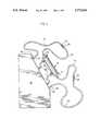
- FIG. 1is plan view of a connected dialyzer, arterial blood set, and venous blood set in accordance with this invention
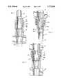
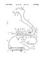
- FIG. 2is a generally schematic elevational view showing the dialyzer and blood sets of FIG. 1 connected to a reuse machine for cleansing of the system for later reuse, with certain set components removed;
- FIGS. 3 and 4are enlarged, detailed longitudinal sectional views illustrating embodiments of joined connectors as used in FIG. 1;
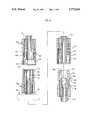
- FIG. 5is an enlarged longitudinal sectional view illustrating two of the connectors of FIGS. 3 and 4 joined together as shown in FIG. 2;
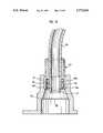
- FIG. 6is an enlarged, exploded longitudinal sectional view showing another embodiment of connectors as they may be joined together in the manner of FIG. 3;
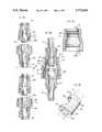
- FIG. 7is an enlarged, longitudinal sectional view showing another embodiment of connectors which are joined together for use in the configuration of FIG. 2;
- FIG. 8ais an enlarged, exploded longitudinal sectional view, showing another connector embodiment in the configuration of FIG. 1;
- FIG. 8bis an enlarged longitudinal sectional view showing two connectors of FIG. 8a in the configuration of FIG. 2;
- FIG. 8cis a longitudinal sectional view of an overconnector used in FIG. 8b;
- FIG. 8dis a perspective view, with portions broken away, of another embodiment of overconnector for use similar to the overconnector of FIG. 8c;
- FIG. 9is a longitudinal sectional view of another embodiment of joined connectors as shown in FIG. 2;
- FIG. 10is a sectional view of the connection of the patient connectors to the reuse machine as shown in FIG. 2;
- FIG. 11is a plan view of another embodiment of a dialyzer connected to a combined arterial-venous blood set in another embodiment of this invention.
- a conventional hemodialyzer 10has a blood inlet 12 which is connected by a conventional luer lock system to first connector 20 at an end of arterial blood set 14. Dialyzer 10 also has a blood outlet 16, which is connected to a first connector 52 of venous set 18. These sets 14, 18 and dialyzer 10 are of conventional design except as otherwise indicated herein in accordance with this invention.
- First connector 20is carried by first branchless, flexible tube 22 of arterial set 14, which first tube terminates in second connector 24.
- Second connector 24communicates with a third connector 26, which is carried by central assembly 28 of arterial set 14.
- first flexible tube 22is preferably without branches or other components except for approximately 100 cm. of plastic tubing, (preferably having an inner diameter of 4.5 to 7 mm. or a lumen cross-sectional area of 0.17 to 0.38 cm 2 )
- central assembly 28may comprise a substantial number of branching and other components carried with tubing segments 29, 30 and 31.
- a length of roller pump tubing 32is provided, shown to be in a roller pump track 33 and being retained in line by a pair of pump tubing connectors 34, 36, designed to accommodate the differing diameters of the respective lines.
- Connector 34may have a branch connecting line 38 which comprises an anti-backup heparin line, as an optional feature.
- a debubbling chamber 40may be provided having conventional branch or side arm lines, one of such lines carrying a transducer protector 42 for conventional pressure measurements.
- another conventional branch line 44may be provided for connection with a source of physiological saline solution.
- Other designs of central assembly 28may also be used.
- Central assembly 28terminates in a fourth connector 46, which communicates with fifth connector 48 of a second length of flexible tubing 50, comprising a single, unbranched tubing length of about 180 cm. length, and having a lumen cross section typically similar to first flexible tube 22.
- arterial set 14may be terminated with a conventional sixth connector 53 of luer lock type.
- componentsmay be added or subtracted to the arterial and venous sets shown.
- an injection site 54 of conventional designmay be placed on the arterial set in the position shown, or any other desirable position, including on reusable tubing conduits 14, 50, 72, or 18.
- Arterial set 14may be used in a conventional dialysis procedure. Then, at the end of the procedure, after the blood has been substantially rinsed from set 14, connectors 24 and 26, and connectors 46, 48 may be respectively disconnected, and central assembly 28 may be removed. Then, connectors 24 and 48 may be connected together in the manner to be shown below.
- the mode of connection between connectors 24 and 48is different from the mode of connection between connectors 24, 26 and 46, 48, so that the first sealing surfaces utilized in sealing contact between the respective connectors 24, 26 and 46, 48 are open and exposed within the connected connectors 24, 28, so that the application of cleaning/storage solution through the set causes cleaning and antibacterial action on these first sealing surfaces.
- Venous blood set 18also comprises a first connector 52, which connects to or is integral with the blood outlet of dialyzer 10, and is carried by a first length of tubing 56, which may be about 80 cm long and is preferably free of branches in a manner similar to the previously described first tubing 22.
- First tubing 56terminates at its other end to second connector 58 which, in turn, communicates with a third connector 60 carried by the central assembly 62 of this blood set 18.
- Central assembly 62comprises a filter-carrying debubbling chamber 64 and preferably branch lines as desired, one of said branch lines carrying a transducer protector 66 in a manner similar to the previous arterial set 14.
- Central assembly 62also carries a fourth connector 68 which is in sealed, connected relation to a fifth connector 70 which is carried upon second length of tubing 72.
- Second length of tubing 72is similar in length and diameter to the other second tubing 50, being also preferably free of branch connections, pressure pillows, injection sites, and other chambers.
- On-off clamps 74are preferably externally carried on the tubings adjacent the respective connectors, and are not deemed an integral feature thereof.
- Second tubing 72 of the venous set 18terminates in a conventional sixth connector 76 of the luer lock type, for patient access connection.
- connectors 58, 60 and 68 and 70may be disconnected, and the preferably specially designed connectors 58, 70 may be connected to each other, preferably in a manner as described above where the original sealing surfaces providing the sealed connection between connectors 58, 60 and 68, 70 are exposed to the connectors' interior for washing and contact with the cleaning/storage solution in preparation for reuse.
- first and second tubings 22, 50, 56, 72comprising in this embodiment about eighteen feet of tubing, can be reused in an indefinite number of dialysis procedures, resulting in substantial savings of plastic and reduced problems of the disposal of biohazard waste.
- central assemblies 28, 62are connected into the respective sets between the respective first and second tubes 22, 50, 56, 72, but if necessary and as possible, central assemblies 28, 62 may be cleaned and rehabilitated for reuse also.
- FIG. 2shows the set of this invention after disconnection of the central assemblies 28, 62, and reconnection of the respective long tubes 22, 50, 56, 72, with the dialyzer 10, and the connected long tubes and dialyzer being mounted on a conventional reuse machine 80.
- Sixth patient connectors 53, 76 of each setmay be connected to special reuse connectors 82, 84 which hold connectors 53, 76 in sealed relation to provide cleaning/storage solution to the system with their first sealing surfaces exposed to the solution so that the surfaces are cleaned.
- short tubes 88 from reuse machine 80connect to the dialysis ports 90 of dialyzer 10, so that cleaning/storage solution, typically a sequence of various types of washing, sterilizing and storage solutions, are applied to the dialyzer and the tubular set components.
- connectors 53, 76may be connected together using an interconnector or an overconnector; the dialysis ports 90 may be closed; and the dialyzer and connected tubing may be removed from reuse machine 80 for storage until the next desired use.
- At least some of the connectors used in this inventiondefine first sealing surfaces that seal with one type of connector, and second sealing surfaces which seal with another type of connector in such a manner that the first sealing surfaces are positioned in exposed manner within the connectors so that antimicrobial solution in the joined connectors can be in contact with the first sealing surfaces.
- This later conditioncorresponds with the situation in FIG. 2, so that the first sealing surfaces can be exposed to the antimicrobial effect of the cleaning agents of reuse machine 80 or any reuse program desired.
- the first sealing surfacesare placed back into sealing operation and do so under aseptic conditions, having been cleaned and subjected to antimicrobial action.
- FIG. 3is an enlarged, longitudinal sectional view of connectors 46, 48 of arterial set 14, showing the connection and the first sealing surface 92 which is generally circular in cross section and formed with screw threads 95 on male portion 94 of connector 46, in sealing relation with first sealing surface 92a on female portion 98 of connector 48.
- FIG. 4shows another design of connector system of the arterial set, namely connectors 24 and 26 in their connected relationship.
- Threaded male sleeve 100 of connector 24is in screw-threaded engagement with female sleeve 102 of connector 26, providing a first sealing surface 104 on male sleeve 100 and in sealing relation with female sleeve 102 at its first sealing surface 104a.
- Connector 24also carries an outer sleeve 106 with inner threads, for use in its second connection.
- the corresponding connectors of venous set 18may be of similar design.
- FIG. 5this shows the situation when central assembly 28 is removed from arterial set 14, and connectors 24, 48 are connected together as illustrated in FIG. 2.
- Sleeve 98 of connector 48threaded both inside and out, is capable of receiving outer sleeve 106 of connector 24 in threaded relation as shown in FIG. 5.
- the outer surface 104 of sleeve 100 of connector 24is inwardly spaced from the inner surface of sleeve 98, 50 that the first sealing surfaces 92a, 104 of the respective connectors are open and accessible to the antimicrobial cleaning/storage solution that is provided in the configuration of FIG. 2 for cleaning of those surfaces 92a, 104.
- the remaining connectors 46, 26are respectively connected to central assemblies 28, 62, which are removed, and do not participate in the process of this invention any further.
- Annular, second sealing surfaces 108, 108aare provided between the inner surface of outer sleeve 106' and the outer surface of sleeve 98, as shown.
- the reusable fifth patient connector 48acorresponding to connector 48 of FIG. 1, can be seen to comprise a female tapered first sealing area 92a' corresponding in function to the threaded seal area 92a of FIG. 3.
- Connector 48amay carry an outer sleeve 110 surrounding most of the taper area and connected at an annular connection 112 with the structure 114 defining female taper surface 92a'.
- Outer sleeve 110carries external threads 116.
- the mating disposable connector 46acorresponds in function to connector 46 of FIG. 1, so that the respective two connectors 48a, 46a connect the second flexible tube 50 with the central assembly 28 of a blood set in accordance with this invention as specifically disclosed in FIG. 1.
- the design of connector 46avaries from connector 46.
- First sealing surface 118comprises a male tapered sleeve.
- Outer sleeve 120carries internal threads 122.
- Male taper surface 118can seal with female luer surface 92a' of connector 48a.
- Outer sleeve 120has internal threads 122 which engage threads 116 of connector 48a in locking relation.
- FIG. 6can represent a detailed view of a preferred design for mating connectors 68, 70 in FIG. 1.
- a disposable third connector 26awhich is similar in function and position to third connector 26 of FIG. 1 but with a different design.
- Male tapered sleeve 109comprises the first sealing surface 111 mating with first sealing surface 124 of second connector 24a, which corresponds in function to connector 24 of FIG. 1.
- male tapered connector 26aseals at the respective first sealing surfaces 111, 124 at conical taper 124 of connector 24a.
- Sleeve 113 of third connector 26acarries threads 115 for engaging the threads 127 of connector 24a.
- connector 48amay be separated and then rejoined with connector 24a as in FIG. 7, to link together the respective first and second tubes 22, 50 of the device of FIG. 1.
- connector 24adefines female taper surface 124, used as the first sealing surface for initial locking with a male connector 26a of central assembly 28 as in FIG. 1.
- outer sleeve 126having internal threads 127, locks with the external threads 116 of outer sleeve 110.
- at least the distal end of outer sleeve 110 of connector 48acomprises a female taper surface 128 which engages with male tapered surface 130, which is defined by projecting member 132 of connector 24a.
- projecting member 132defines female taper surface 124 on the inside and a male taper surface 130 on its exterior, the latter including the respective second sealing area 130, 128 that provide the second seal between connectors 24a, 48a.
- the connectors 24a, 48acan form an aseptic seal in their respective first sealing areas 92a', 124.
- FIG. 8ashows a detailed modification of FIG. 1, in which the first tube 22 is terminated by connector 24b, which is shown to be a male luer lock-type connector capable of connecting with connector 26b in a manner analogous to the previously described connectors 24, 26.
- Second tubing 50connects with fourth connector 48b, which is a female-type luer lock connector and which connects with connector 46b in a manner similar to the previous connectors 46, 48.
- FIG. 8ba detail from the situation of FIG. 2 is shown, where central assembly 28 and second and third connectors 26b, 46b have been removed, with connectors 24b, 48b being brought together in connected but spaced relationship by an overconnector 136.
- Each of connectors 24b, 48brespectively carry an integral locking ring 132 and sleeve 134.
- Connector 48bmay be of the conventional design for a female luer connector but with this added, integral outer sleeve 134.
- Locking ring 132has internal threads 132a, while sleeve 134 may be without threads.
- overconnector 136is provided, being of generally tubular form, to enclose and to retain the respective locking rings 132, 134 of the connectors in sealed, spaced relation as shown.
- Overconnector 136may be made of a somewhat resilient material so that the respective connectors 24b, 48b may be each connected to it in snap-fit relation.
- overconnector 136defines an inner, annular spacing member 142 to provide inner spacing for connectors 24b, 48b by engagement of the sleeves 132, 134 with member 142.
- the respective second seal area of connector 24bmay comprise the outer surface 133 of sleeve 132, while the second seal of connector 48b comprises the outer surface 135 of sleeve 134. It can be seen that the first seal area for connector 24b is the conventional male luer taper surface 144, while the first sealing surface for connector 48b is the female luer taper surface 146.
- Connector 26bcan be seen to be of identical design to connector 48b, while connector 46b may be identical in design to connector 24b. This simplifies both the molding cost and the manufacture of the system, since the number of designs is reduced.
- Overconnector 136may have optional end retaining members 138, 140, performing as snap-fit detents, which may be continuously annular or interrupted projections as desired, for retention of the respective connectors pressing inwardly against inner annular spacing member 142. Overconnector 136 may also be of differing end diameters as shown to accommodate the differently sized sleeves 132, 134. Also, overconnector 136 may carry integral sealing rings 143, 143a to press against the respective outer surfaces 133, 135 of sleeves 132, 134 to provide the desired second seal in the second sealing area.
- a sealed connectioncan be provided between the respective connectors 24b, 48b, by the use of overconnector 136, so that a sealed connection is provided without the use of the respective luer taper surfaces 144, 146 of the respective connectors. Rather, these surfaces 144, 146 are exposed to the flow of fluid through the respective flexible tubes 22, 50 so that these first sealing areas 144, 146 can be cleaned and exposed to antimicrobial activity. Thus they may be reused in an aseptic seal with a new central assembly 28.
- overconnector 136aa perspective view of another overconnector 136a is shown. While it is shown to be tubular in nature, it may be molded of a single shot of plastic having a plastic living hinge 150 so that it forms two pivotable semicylindrical halves 152, 154 connected together by a conventional clasp 155. Retaining, annular endwalls 154 may be provided at each end, plus a central, inner ring 157 or the like to space the connectors in the overconnector. Thus, overconnector 136 may be applied laterally to the respective connectors 24b, 48b and snapped together to form the desired sealed connection for the processing phase of the set prior to reuse, per FIG. 2.
- overconnector 136may simply comprise an interference fit tube, optionally with inner, annular sealing member 142, to provide second seal areas 141, 143.
- a tubemay be elastomeric, for example silicone or thermoplastic elastomer.
- FIG. 9another embodiment for the connectors shown in the connections of FIG. 2 is shown.
- Connectors 24c, 48cmay be used as replacements for connectors 24, 48, and also connectors 58, 70 as shown in FIG. 2. These connectors have been previously connected as correspondingly shown in FIG. 1 with other connectors which may be disposable. Now, the respective first and second tubes 22, 50 are brought together as in FIG. 2 for the purposes described above.
- connector 24cdefines an aperture having a first, outer bore 200 of a diameter which is greater than inner bore 202 of the aperture shown.
- a first O-ring 204is provided in the inner bore portion 202, while a second O-ring 206 is provided to the outer bore portion 200.
- Connector 48cdefines a lumen 207 extending through it, and a tubular projection having an inner portion 208 of a diameter that is greater than the diameter of an outer projection portion 210.
- Outer projection portion 210carries another O-ring 212.
- O-ring 206may be carried on the first projection portion 208 rather than the inner surface of bore portion 200.
- the technology used with respect to the specific O-rings with respect to their securance and the materials of which they are formedmay be conventional.
- connectors 24c and 48cmay replace connectors 24, 48 (and connectors 58, 70) in the embodiment of FIG. 2, they are also capable of connecting with other connectors as indicated in the embodiment of FIG. 1 so that the desired central assembly may be placed between the respective connectors.
- the connectors of the central assemblymay be proportioned to form a seal with the respective O-rings 204, 212, so that these seals define the respective first sealing areas (as previously discussed) for the connectors 24c, 48c. Then, when the central assembly is to be disconnected and removed, the respective connectors 24c, 48c may be brought together as shown in FIG.
- O-ring 206comprising the second seal area (discussed previously) while the respective first O-rings 204, 212 are exposed as is desired for the first seal areas to contact with antiseptic solution passing through conduits 22, 50, to permit their restoration back into aseptic condition for reuse, along with tubes 22, 50.
- sixth connector 53is shown in its connected relation with reuse port connector 82 which, in turn, is connected to the reuse apparatus 80 as shown in FIG. 2.
- the connection of sixth connector 76 with reuse port connector 84may be of similar design.
- Reuse port 82has a first annular sealing surface 81 and an annular stop 83.
- Connector 53defines a conventional first annular sealing surface 77 comprising a male taper, for use in its connection with a fistula needle set or the like while blood is being circulated through the system.
- Connector 53also carries a conventional sleeve 78 having locking threads 78a.
- the outer annular surface 79 of sleeve 78may then serve as the second sealing surface in accordance with this invention, engaging with the annular sealing surface 81 of reuse port 82, for sealing engagement while in the configuration of FIGS. 2 and 10.
- the male taper first sealing area 77may also be cleaned and disinfected prior to storage and reuse of the set.
- Reuse port 82may be somewhat flexible and resilient so that connector 53 can snap-fit into and out of recess 81a defined by connector 82 at the sealing surface area 81.
- dialyzer 10may be identical to the dialyzer of FIG. 1.
- the first tubing 22 of the arterial setmay connect through first connector 20 to blood inlet 12 of the dialyzer.
- First tubing 22may be identical to the tubing of FIG. 1, connecting by connector 24 to a different central assembly.
- central assembly 160serves the function of both of the central assemblies of FIG. 1, with respective first and second lines 22, 50, 56, and 72 being connected thereto, the latter four blood lines being identical if desired to those of FIG. 1.
- Connector 161connects to roller pump tubing 32a of central assembly 160, with a branching heparin line 38a being provided if desired.
- Roller pump 32aconnects to double chamber unit 162, typically made of a blow molded plastic parison, and being made of a substantially stiff plastic although more resilient material may be used if desired.
- a branch connector line 166is defined by structure 162 to connect to a saline line 168.
- a top port 167permits connection to a transducer line 169.
- An outlet port 170communicates with tubing 172 that carries an injection site 174 and outlet connector 176, which may correspond in structure and function to connector 46 of FIG. 1.
- Connector 176may connect with fifth connector 48 of second flexible tubing 50, which may be identical to the corresponding second tube of FIG. 1.
- Second flexible tube 50terminates in a sixth patient connector 52, shown to be connected to a fistula needle and tube 178 of conventional design. Thus the arterial set is shown.
- blood outlet 16 of dialyzer 10is connected to connector 52 of the first venous tubular portion 22, identical if desired with the corresponding structure of FIG. 1.
- First tube 56terminates in second connector 58 as before, and communicates with third venous connector 180 of the structure, communicating with conduit 182 that leads to second chamber 184.
- Chamber 184also has branch ports providing communication with the chamber for transducer protector line 186 and another line 188.
- Chamber 184has a bottom exit through filter 190 which may be integrally attached and of a design similar to that shown in U.S. Pat. No. 5,328,461.
- Bottom exit portcommunicates with tubing 192 which carries an injection site and fourth connector 196, which may be similar in structure and function to connector 68 of FIG. 1.
- Connector 70is carried by second venous tube 72, which may be identical to tube 72 of FIG. 1. Second venous tube 72 is terminated by a sixth connector 76, shown to be in communication with another fistula needle and tube 198.
- this systemmay function in the manner similar to the arrangement of FIG. 1, using any of the connector designs shown herein and others as well, to provide dialysis to a patient, the blood access being through fistula sets 178, 198.
- connectors 24, 48may be separated and connected to each other, while connectors 58, 70 may be similarly separated and connected to each other, so that the multiple chamber central assembly 162 is removed, and the system assumes the configuration of FIG. 2 for washing, sterilization, and storage until reuse is again desired of the dialyzer and tubing.
Landscapes
- Health & Medical Sciences (AREA)
- Heart & Thoracic Surgery (AREA)
- Vascular Medicine (AREA)
- Life Sciences & Earth Sciences (AREA)
- Engineering & Computer Science (AREA)
- Anesthesiology (AREA)
- Biomedical Technology (AREA)
- Hematology (AREA)
- Animal Behavior & Ethology (AREA)
- General Health & Medical Sciences (AREA)
- Public Health (AREA)
- Veterinary Medicine (AREA)
- Cardiology (AREA)
- Urology & Nephrology (AREA)
- Emergency Medicine (AREA)
- External Artificial Organs (AREA)
Abstract
Description
Claims (21)
Priority Applications (7)
| Application Number | Priority Date | Filing Date | Title |
|---|---|---|---|
| US08/504,457US5772624A (en) | 1995-07-20 | 1995-07-20 | Reusable blood lines |
| CA002181024ACA2181024A1 (en) | 1995-07-20 | 1996-07-11 | Reusable blood lines |
| EP96111732AEP0754468A3 (en) | 1995-07-20 | 1996-07-20 | Reusable blood lines |
| JP8212080AJPH09122230A (en) | 1995-07-20 | 1996-07-22 | Reusable blood line |
| US08/892,685US6165149A (en) | 1995-07-20 | 1997-07-14 | Reusable blood lines |
| US09/664,432US6620119B1 (en) | 1995-07-20 | 2000-09-18 | Reusable blood lines |
| US10/313,695US6666839B2 (en) | 1995-07-20 | 2002-12-06 | Method of using reusable blood lines |
Applications Claiming Priority (1)
| Application Number | Priority Date | Filing Date | Title |
|---|---|---|---|
| US08/504,457US5772624A (en) | 1995-07-20 | 1995-07-20 | Reusable blood lines |
Related Child Applications (1)
| Application Number | Title | Priority Date | Filing Date |
|---|---|---|---|
| US08/892,685DivisionUS6165149A (en) | 1995-07-20 | 1997-07-14 | Reusable blood lines |
Publications (1)
| Publication Number | Publication Date |
|---|---|
| US5772624Atrue US5772624A (en) | 1998-06-30 |
Family
ID=24006352
Family Applications (4)
| Application Number | Title | Priority Date | Filing Date |
|---|---|---|---|
| US08/504,457Expired - LifetimeUS5772624A (en) | 1995-07-20 | 1995-07-20 | Reusable blood lines |
| US08/892,685Expired - LifetimeUS6165149A (en) | 1995-07-20 | 1997-07-14 | Reusable blood lines |
| US09/664,432Expired - Fee RelatedUS6620119B1 (en) | 1995-07-20 | 2000-09-18 | Reusable blood lines |
| US10/313,695Expired - Fee RelatedUS6666839B2 (en) | 1995-07-20 | 2002-12-06 | Method of using reusable blood lines |
Family Applications After (3)
| Application Number | Title | Priority Date | Filing Date |
|---|---|---|---|
| US08/892,685Expired - LifetimeUS6165149A (en) | 1995-07-20 | 1997-07-14 | Reusable blood lines |
| US09/664,432Expired - Fee RelatedUS6620119B1 (en) | 1995-07-20 | 2000-09-18 | Reusable blood lines |
| US10/313,695Expired - Fee RelatedUS6666839B2 (en) | 1995-07-20 | 2002-12-06 | Method of using reusable blood lines |
Country Status (4)
| Country | Link |
|---|---|
| US (4) | US5772624A (en) |
| EP (1) | EP0754468A3 (en) |
| JP (1) | JPH09122230A (en) |
| CA (1) | CA2181024A1 (en) |
Cited By (26)
| Publication number | Priority date | Publication date | Assignee | Title |
|---|---|---|---|---|
| US5948251A (en)* | 1995-06-07 | 1999-09-07 | Cobe Laboratories, Inc. | Technique for using a dialysis machine to disinfect a blood tubing set |
| US6290665B1 (en)* | 1996-09-23 | 2001-09-18 | Dsu Medical Corporation | Blood set priming method and apparatus |
| US6344139B1 (en) | 1997-10-21 | 2002-02-05 | Dsu Medical Corporation | Arterial and venous blood tubing set |
| US6387069B1 (en) | 1996-09-23 | 2002-05-14 | Dsu Medical Corporation | Blood set priming method and apparatus |
| US20020151834A1 (en)* | 1996-09-23 | 2002-10-17 | Utterberg David S. | Blood set priming method and apparatus |
| US20030010717A1 (en)* | 2001-07-13 | 2003-01-16 | Nx Stage Medical, Inc. | Systems and methods for handling air and/or flushing fluids in a fluid circuit |
| US20030100857A1 (en)* | 2000-01-12 | 2003-05-29 | Renato Pedrazzi | Method for emptying a blood circuit of an apparatus for the extracorporeal treatment of blood |
| US20050132826A1 (en)* | 2003-12-23 | 2005-06-23 | Ludwig Teugels | Double membrane transducer protector |
| US20050150831A1 (en)* | 1997-06-23 | 2005-07-14 | Princeton Trade And Technology, Inc. | Method for cleaning hollow tubing and fibers |
| US20050277906A1 (en)* | 2003-03-20 | 2005-12-15 | James Brugger | Dual access spike for infusate bags |
| US7008535B1 (en) | 2000-08-04 | 2006-03-07 | Wayne State University | Apparatus for oxygenating wastewater |
| US20070014689A1 (en)* | 2003-12-23 | 2007-01-18 | Jms North America Corporation | Double membrane transducer protector |
| US20090229632A1 (en)* | 1997-06-23 | 2009-09-17 | Princeton Trade And Technology | Apparatus and method for cleaning pipelines, tubing and membranes using two-phase flow |
| US20100078046A1 (en)* | 2008-09-30 | 2010-04-01 | Mohamed Emam Labib | Apparatus and method for cleaning passageways such as endoscope channels using flow of liquid and gas |
| US7862660B2 (en) | 2007-01-12 | 2011-01-04 | Princeton Trade & Technology, Inc. | Device and method for fluid dynamics cleaning of constrained spaces |
| US8114221B2 (en) | 2008-09-30 | 2012-02-14 | Princeton Trade & Technology, Inc. | Method and composition for cleaning tubular systems employing moving three-phase contact lines |
| US20140271293A1 (en)* | 2013-03-14 | 2014-09-18 | Blue-White Industries, Ltd. | High pressure, high flow rate tubing assembly and adapter for a positive displacement pump |
| US20170216571A1 (en)* | 2014-08-05 | 2017-08-03 | Fresenius Medical Care Deutschland Gmbh | Method of increasing the leak tightness of a mechanical connector |
| US20170246369A1 (en)* | 2014-10-17 | 2017-08-31 | Debiotech S.A. | Handle for a Medical Device |
| US10515534B1 (en) | 2018-06-19 | 2019-12-24 | Fresenius Medical Care Holdings, Inc. | Blood treatment machine with blood pressure measurement notification |
| WO2020181007A1 (en)* | 2019-03-04 | 2020-09-10 | Somnus Medical, LLC | Iv extension set or iv set system with bypass manifold |
| US11058813B2 (en) | 2013-08-12 | 2021-07-13 | Somnus Medical, LLC | IV extension set or IV set system with bypass manifold |
| US11131300B2 (en) | 2010-01-22 | 2021-09-28 | Blue-White Industries, Ltd. | Overmolded tubing assembly and adapter for a positive displacement pump |
| US11420037B2 (en) | 2017-08-04 | 2022-08-23 | Fresenius Medical Care Holdings, Inc. | Infusion methods for extracoporeal systems |
| US11491269B2 (en)* | 2020-01-21 | 2022-11-08 | Fresenius Medical Care Holdings, Inc. | Arterial chambers for hemodialysis and related systems and tubing sets |
| US11578716B2 (en) | 2010-01-22 | 2023-02-14 | Blue-White Industries, Ltd. | Overmolded tubing assembly and adapter for a positive displacement pump |
Families Citing this family (86)
| Publication number | Priority date | Publication date | Assignee | Title |
|---|---|---|---|---|
| US5772624A (en)* | 1995-07-20 | 1998-06-30 | Medisystems Technology Corporation | Reusable blood lines |
| US5951508A (en)* | 1997-09-29 | 1999-09-14 | Medtronic, Inc. | Bilaterally connectable softshell reservoir |
| DE60043476D1 (en)* | 1999-01-12 | 2010-01-21 | Gambro Ind Sas | Device for dialysis with heating of the blood |
| US6375231B1 (en)* | 2000-03-10 | 2002-04-23 | Applied Medical Technology, Inc. | Enteral feeding clamp |
| WO2002066100A2 (en)* | 2001-02-20 | 2002-08-29 | Medrad, Inc. | Syringes, connectors, and syringe and connector systems for use in fluid delivery systems |
| US6916248B1 (en)* | 2002-01-31 | 2005-07-12 | Ps Technology, Inc. | Flexible coupling |
| US6722705B2 (en)* | 2002-04-25 | 2004-04-20 | Ab Korkor Medical, Inc. | Medical tubing connector |
| JP4362036B2 (en)* | 2003-01-10 | 2009-11-11 | 川澄化学工業株式会社 | Connector member for extracorporeal circuit and body fluid circulation treatment device |
| US7559911B2 (en)* | 2003-09-05 | 2009-07-14 | Gambro Lundia Ab | Blood chamber for extracorporeal blood circuits and a process for manufacturing the blood chamber |
| US7846137B2 (en)* | 2003-12-26 | 2010-12-07 | Medtronic Minimed, Inc. | Modular catheter system |
| JP4273971B2 (en)* | 2004-01-07 | 2009-06-03 | ニプロ株式会社 | Female connector |
| US7556619B2 (en)* | 2004-04-16 | 2009-07-07 | Medrad, Inc. | Fluid delivery system having a fluid level sensor and a fluid control device for isolating a patient from a pump device |
| US7842001B2 (en)* | 2005-01-07 | 2010-11-30 | Jms Co. | Automatic priming method |
| AU2006331039B2 (en)* | 2005-12-28 | 2012-01-12 | Cardinal Health 529, Llc | Male luer connector |
| US7794141B2 (en) | 2006-04-14 | 2010-09-14 | Deka Products Limited Partnership | Thermal and coductivity sensing systems, devices and methods |
| US9717834B2 (en) | 2011-05-24 | 2017-08-01 | Deka Products Limited Partnership | Blood treatment systems and methods |
| US8273049B2 (en) | 2007-02-27 | 2012-09-25 | Deka Products Limited Partnership | Pumping cassette |
| US10537671B2 (en) | 2006-04-14 | 2020-01-21 | Deka Products Limited Partnership | Automated control mechanisms in a hemodialysis apparatus |
| JP4971728B2 (en)* | 2006-08-31 | 2012-07-11 | 日本コヴィディエン株式会社 | Connector connection structure |
| US8257286B2 (en) | 2006-09-21 | 2012-09-04 | Tyco Healthcare Group Lp | Safety connector apparatus |
| US8221363B2 (en) | 2006-10-18 | 2012-07-17 | Baxter Healthcare S.A. | Luer activated device with valve element under tension |
| US7981090B2 (en) | 2006-10-18 | 2011-07-19 | Baxter International Inc. | Luer activated device |
| US7753338B2 (en) | 2006-10-23 | 2010-07-13 | Baxter International Inc. | Luer activated device with minimal fluid displacement |
| US9028691B2 (en) | 2007-02-27 | 2015-05-12 | Deka Products Limited Partnership | Blood circuit assembly for a hemodialysis system |
| US8042563B2 (en) | 2007-02-27 | 2011-10-25 | Deka Products Limited Partnership | Cassette system integrated apparatus |
| US8409441B2 (en) | 2007-02-27 | 2013-04-02 | Deka Products Limited Partnership | Blood treatment systems and methods |
| US8393690B2 (en)* | 2007-02-27 | 2013-03-12 | Deka Products Limited Partnership | Enclosure for a portable hemodialysis system |
| WO2010027437A2 (en)* | 2007-02-27 | 2010-03-11 | Deka Products Limited Partnership | Blood treatment systems and methods |
| US8491184B2 (en) | 2007-02-27 | 2013-07-23 | Deka Products Limited Partnership | Sensor apparatus systems, devices and methods |
| KR102444304B1 (en) | 2007-02-27 | 2022-09-19 | 데카 프로덕츠 리미티드 파트너쉽 | hemodialysis system |
| US8357298B2 (en) | 2007-02-27 | 2013-01-22 | Deka Products Limited Partnership | Hemodialysis systems and methods |
| US20090107335A1 (en) | 2007-02-27 | 2009-04-30 | Deka Products Limited Partnership | Air trap for a medical infusion device |
| US8562834B2 (en) | 2007-02-27 | 2013-10-22 | Deka Products Limited Partnership | Modular assembly for a portable hemodialysis system |
| US8770190B2 (en)* | 2007-04-25 | 2014-07-08 | Resmed Limited | Connectors for connecting components of a breathing apparatus |
| FR2917628B1 (en)* | 2007-06-19 | 2009-09-18 | Commissariat Energie Atomique | FLUIDIC CONNECTION DEVICE, SYSTEM AND METHOD FOR CONTINUOUSLY SAMPLING FLUID MICROECHANTILLES USING THE DEVICE. |
| US8562908B2 (en) | 2007-06-29 | 2013-10-22 | Baxter International Inc. | Devices, systems, and methods for cleaning, disinfecting, rinsing, and priming blood separation devices and associated fluid lines |
| US20100056975A1 (en)* | 2008-08-27 | 2010-03-04 | Deka Products Limited Partnership | Blood line connector for a medical infusion device |
| US10201647B2 (en) | 2008-01-23 | 2019-02-12 | Deka Products Limited Partnership | Medical treatment system and methods using a plurality of fluid lines |
| US11833281B2 (en) | 2008-01-23 | 2023-12-05 | Deka Products Limited Partnership | Pump cassette and methods for use in medical treatment system using a plurality of fluid lines |
| US11738130B2 (en) | 2008-01-23 | 2023-08-29 | Deka Products Limited Partnership | Fluid line autoconnect apparatus and methods for medical treatment system |
| US8708950B2 (en) | 2010-07-07 | 2014-04-29 | Deka Products Limited Partnership | Medical treatment system and methods using a plurality of fluid lines |
| JP5595930B2 (en) | 2008-01-23 | 2014-09-24 | デカ・プロダクツ・リミテッド・パートナーシップ | Disposable components for fluid line automatic connection systems |
| US8257287B2 (en)* | 2008-03-20 | 2012-09-04 | Tyco Healthcare Group Lp | Safety connector assembly |
| US8708376B2 (en)* | 2008-10-10 | 2014-04-29 | Deka Products Limited Partnership | Medium connector |
| US12186531B2 (en) | 2008-10-10 | 2025-01-07 | Deka Products Limited Partnership | Infusion pump assembly |
| US12370327B2 (en) | 2008-10-10 | 2025-07-29 | Deka Products Limited Partnership | Infusion pump methods, systems and apparatus |
| EP2456355B1 (en)* | 2009-07-20 | 2016-09-14 | Optiscan Biomedical Corporation | Adjustable connector and dead space reduction |
| DE202010000078U1 (en)* | 2010-01-22 | 2011-05-26 | Hopf, Hans-Jürgen, 90513 | Fluid-flow connection systems for use in medicine and medical technology |
| DE202009005077U1 (en)* | 2009-07-28 | 2010-12-23 | Fa. Hans Jürgen Hopf | Connection system for fluid connections |
| ITRM20090523A1 (en)* | 2009-10-09 | 2011-04-10 | Over S R L | EQUIPMENT FOR EXTRACORPROOF HEMODIALYSIS PREPARED FOR THE DECONTAMINATION OF LINES AND FILTERS. |
| CN104841030B (en) | 2009-10-30 | 2017-10-31 | 德卡产品有限公司 | For the apparatus and method for the disconnection for detecting intravascular access device |
| US8753515B2 (en) | 2009-12-05 | 2014-06-17 | Home Dialysis Plus, Ltd. | Dialysis system with ultrafiltration control |
| WO2011140073A2 (en) | 2010-05-03 | 2011-11-10 | Optiscan Biomedical Corporation | Adjustable connector, improved fluid flow and reduced clotting risk |
| WO2011153302A2 (en)* | 2010-06-02 | 2011-12-08 | Zarate Alfredo R | Hemodialysis system and method |
| US8501009B2 (en) | 2010-06-07 | 2013-08-06 | State Of Oregon Acting By And Through The State Board Of Higher Education On Behalf Of Oregon State University | Fluid purification system |
| EP3205362B1 (en) | 2011-05-24 | 2022-07-06 | DEKA Products Limited Partnership | Hemodialysis system |
| CA2834399C (en) | 2011-05-27 | 2019-05-21 | Gambro Lundia Ab | Blood treatment apparatus adapted to preserve parts thereof |
| JP2014533133A (en) | 2011-10-07 | 2014-12-11 | ホーム・ダイアリシス・プラス・リミテッドHome DialysisPlus, Ltd. | Purification of heat exchange fluids for dialysis systems |
| RU2623490C2 (en) | 2011-10-19 | 2017-06-26 | БАЙЕР ХелсКер ЛЛСи | Sterile maintaining medical connector unit and method |
| FR2982162B1 (en)* | 2011-11-08 | 2013-11-22 | Vygon | CONNECTION ASSEMBLY FOR REALIZING FLUID TRANSMISSION IN THE FIELD OF MEDICAL EQUIPMENT |
| US9364655B2 (en) | 2012-05-24 | 2016-06-14 | Deka Products Limited Partnership | Flexible tubing occlusion assembly |
| US10226571B2 (en)* | 2013-03-14 | 2019-03-12 | Carefusion 303, Inc. | Pump segment placement |
| US9968739B2 (en) | 2013-03-14 | 2018-05-15 | Carefusion 303, Inc. | Rotary valve for a disposable infusion set |
| US9522224B2 (en) | 2013-03-14 | 2016-12-20 | Carefusion 303, Inc. | Inductively powered modular medical device system |
| US9468714B2 (en) | 2013-03-14 | 2016-10-18 | Carefusion 303, Inc. | Memory and identification associated with IV set |
| GB201305755D0 (en) | 2013-03-28 | 2013-05-15 | Quanta Fluid Solutions Ltd | Re-Use of a Hemodialysis Cartridge |
| KR20160021194A (en) | 2013-06-14 | 2016-02-24 | 바이엘 메디컬 케어 인크. | Portable fluid delivery system |
| JP6387253B2 (en)* | 2013-07-05 | 2018-09-05 | 日機装株式会社 | Connector and blood purification apparatus to which the connector is attached |
| GB201314512D0 (en) | 2013-08-14 | 2013-09-25 | Quanta Fluid Solutions Ltd | Dual Haemodialysis and Haemodiafiltration blood treatment device |
| HRP20241397T1 (en) | 2014-01-10 | 2024-12-20 | Bayer Healthcare Llc | CONNECTOR FOR DISPOSABLE KIT |
| EP3838308A1 (en) | 2014-04-29 | 2021-06-23 | Outset Medical, Inc. | Dialysis system and methods |
| GB201409796D0 (en) | 2014-06-02 | 2014-07-16 | Quanta Fluid Solutions Ltd | Method of heat sanitization of a haemodialysis water circuit using a calculated dose |
| US10507319B2 (en) | 2015-01-09 | 2019-12-17 | Bayer Healthcare Llc | Multiple fluid delivery system with multi-use disposable set and features thereof |
| GB201523104D0 (en) | 2015-12-30 | 2016-02-10 | Quanta Fluid Solutions Ltd | Dialysis machine |
| GB2547214A (en) | 2016-02-10 | 2017-08-16 | Quanta Fluid Solutions Ltd | Membrane pump usage condition detection |
| TWI651107B (en) | 2016-06-15 | 2019-02-21 | 拜耳保健公司 | Multi-use disposable system and syringe therefor |
| EP3500317B1 (en) | 2016-08-19 | 2022-02-23 | Outset Medical, Inc. | Peritoneal dialysis system and methods |
| GB201622119D0 (en) | 2016-12-23 | 2017-02-08 | Quanta Dialysis Tech Ltd | Improved valve leak detection system |
| GB201701740D0 (en) | 2017-02-02 | 2017-03-22 | Quanta Dialysis Tech Ltd | Phased convective operation |
| GB201710546D0 (en) | 2017-06-30 | 2017-08-16 | Quanta Dialysis Tech Ltd | Dialysis systems, devices and methods |
| USD907211S1 (en) | 2017-09-28 | 2021-01-05 | Quanta Dialysis Technologies Ltd. | Dialysis machine |
| US12201762B2 (en) | 2018-08-23 | 2025-01-21 | Outset Medical, Inc. | Dialysis system and methods |
| JP6880097B2 (en)* | 2019-03-29 | 2021-06-02 | 三菱電機株式会社 | Tube cleaning device |
| WO2020223500A1 (en) | 2019-04-30 | 2020-11-05 | Outset Medical, Inc. | Dialysis system and methods |
| GB2584335A (en) | 2019-05-31 | 2020-12-02 | Quanta Dialysis Technologies Ltd | Source container connector |
| US20220370697A1 (en)* | 2021-03-31 | 2022-11-24 | The Johns Hopkins University | Device and Method to Produce Dialysate |
Citations (43)
| Publication number | Priority date | Publication date | Assignee | Title |
|---|---|---|---|---|
| US3753493A (en)* | 1971-04-23 | 1973-08-21 | E Mellor | Artificial kidney cleaning apparatus |
| US3861388A (en)* | 1973-07-30 | 1975-01-21 | Robert Lee Vaughn | Apparatus for administering supplemental medication with parenteral solutions |
| US3871913A (en)* | 1972-03-14 | 1975-03-18 | Dialysis Systems Limited | Cleaning of dialyser compartments and blood lines of artificial kidney machine |
| US3992301A (en)* | 1973-11-19 | 1976-11-16 | Raypak, Inc. | Automatic flushing system for membrane separation machines such as reverse osmosis machines |
| US3994293A (en)* | 1974-05-07 | 1976-11-30 | Crinospital S.P.A. | Injector assembly for use in transfusions and perfusions |
| US4158034A (en)* | 1976-10-14 | 1979-06-12 | Gambro Ab | Sterilization method and apparatus for dialysis system |
| GB2021418A (en)* | 1978-05-18 | 1979-12-05 | Baxter Travenol Lab | Medical set for a diffusion device |
| US4197848A (en)* | 1978-01-06 | 1980-04-15 | Baxter Travenol Laboratories, Inc. | Closed urinary irrigation site |
| US4361485A (en)* | 1979-07-03 | 1982-11-30 | Wafilin B.V. | Method of and apparatus for washing and cleaning membrane filtration units |
| US4399030A (en)* | 1981-04-28 | 1983-08-16 | Cobe Laboratories, Inc. | Rinsing, cleaning and disinfecting dialysate preparation and supply apparatus |
| EP0090093A1 (en)* | 1982-03-26 | 1983-10-05 | Kawasumi Laboratories Inc. | A humors processing device |
| US4447230A (en)* | 1981-08-05 | 1984-05-08 | Quest Medical, Inc. | Intravenous administration set assembly |
| US4493705A (en)* | 1982-08-10 | 1985-01-15 | Bentley Laboratories, Inc. | Blood reservoir |
| US4559043A (en)* | 1984-10-29 | 1985-12-17 | Drs Infusion Systems, Inc. | Assembly with septum fitting for connecting adaptor and fluid tube |
| US4612170A (en)* | 1983-06-13 | 1986-09-16 | Luther Ronald B | Blood oxygenator with dual sparger and reuseable heat exchanger |
| US4654026A (en)* | 1984-12-26 | 1987-03-31 | Underwood Mara Z | Intravascular tube assembly |
| US4673506A (en)* | 1983-05-28 | 1987-06-16 | Akzo Nv | Cleaning treatment for blood compartments of dialyzators |
| US4695385A (en)* | 1985-04-29 | 1987-09-22 | Colorado Medical, Inc. | Dialyzer reuse system |
| EP0256640A2 (en)* | 1986-06-20 | 1988-02-24 | Bieffe Medital S.A. | Connecting device for peritoneal dialysis |
| US4752292A (en)* | 1983-01-24 | 1988-06-21 | Icu Medical, Inc. | Medical connector |
| US4867739A (en)* | 1982-03-26 | 1989-09-19 | Kawasumi Laboratories Inc. | Sterilizing method |
| US4871353A (en)* | 1987-06-24 | 1989-10-03 | John Thomsen | Method and apparatus for injecting fluids into IV line |
| US4966585A (en)* | 1988-05-31 | 1990-10-30 | Gangemi Ronald J | Infusion apparatus |
| US4976685A (en)* | 1988-06-15 | 1990-12-11 | Block Jr Frank E | Method of blood-gas interface control in surgical gas traps |
| US4981469A (en)* | 1988-04-18 | 1991-01-01 | Dij Catheter Corp. | Septum adapter assembly and external needle adapter fitting |
| EP0442310A1 (en)* | 1990-02-15 | 1991-08-21 | GAMBRO DIALYSATOREN GMBH & CO. KG | A nipple intended to cooperate with multiple coupling components |
| US5061365A (en)* | 1991-01-22 | 1991-10-29 | Utterberg David S | Medical fluid flow set |
| US5071413A (en)* | 1990-06-13 | 1991-12-10 | Utterberg David S | Universal connector |
| US5078699A (en)* | 1989-09-22 | 1992-01-07 | Habley Medical Technology Corporation | Compact, easy to assemble, safety IV system |
| US5139483A (en)* | 1990-05-07 | 1992-08-18 | Ryan Medical, Inc. | Medical intravenous administration line connector |
| US5139675A (en)* | 1990-08-08 | 1992-08-18 | Arnold Edward R | Filtration cleaning system |
| US5203771A (en)* | 1989-06-26 | 1993-04-20 | University Of Florida | Arterial/venous fluid transfer system |
| US5224932A (en)* | 1988-09-27 | 1993-07-06 | Venivee, Inc. | System for intravenous administration of a plurality of medicaments and/or nutrients |
| US5242392A (en)* | 1992-02-13 | 1993-09-07 | Vaughn Dale T | Intravenous piggyback flush apparatus |
| US5256371A (en)* | 1989-12-13 | 1993-10-26 | Medical Support Gmbh | Method and arrangement for disinfecting a dialysis fluid circuit |
| US5268144A (en)* | 1989-11-04 | 1993-12-07 | Fresenius Ag | Method for sterilizing a medical unit |
| US5330425A (en)* | 1992-04-30 | 1994-07-19 | Utterberg David S | Blow molded venous drip chamber for hemodialysis |
| US5344568A (en)* | 1991-10-11 | 1994-09-06 | Children's Hospital Medical Center | Hemofiltration system and method |
| US5360395A (en)* | 1993-12-20 | 1994-11-01 | Utterberg David S | Pump conduit segment having connected, parallel branch line |
| US5484397A (en)* | 1991-08-21 | 1996-01-16 | Twardowski; Zbylut J. | Artificial kidney for frequent (daily) hemodialysis |
| US5490925A (en)* | 1992-03-13 | 1996-02-13 | Medical Support Gmbh | Assembly for the on-line flushing and filling of an extracorporeal blood circulation system of dialysis machines |
| US5589070A (en)* | 1993-07-16 | 1996-12-31 | Cobe Laboratories, Inc. | Method and apparatus for cleaning a dialysate circuit downstream of a dialyzer |
| US5591344A (en)* | 1995-02-13 | 1997-01-07 | Aksys, Ltd. | Hot water disinfection of dialysis machines, including the extracorporeal circuit thereof |
Family Cites Families (14)
| Publication number | Priority date | Publication date | Assignee | Title |
|---|---|---|---|---|
| GB2060399B (en)* | 1979-09-25 | 1983-09-28 | Avon Medicals | Peritoneal dialysis equipment |
| DE8001665U1 (en)* | 1980-01-23 | 1980-04-24 | Asid Bonz & Sohn Gmbh, 8044 Unterschleissheim | DIALYSIS HOSE SYSTEM |
| IL64001A0 (en)* | 1981-10-06 | 1982-01-31 | Elmar Medical Systems Ltd | Blood treatment system |
| US4432759A (en)* | 1982-04-26 | 1984-02-21 | Abbott Laboratories | Connecting device for medical liquid containers |
| JPS59118160A (en)* | 1982-12-27 | 1984-07-07 | 日本ゼオン株式会社 | Air-bubble free connection of blood filling tube |
| US4658915A (en)* | 1985-12-06 | 1987-04-21 | Vetco Gray Inc. | Easy break-out tool joint and method |
| EP0230864A1 (en)* | 1986-01-31 | 1987-08-05 | Vincenzo Buoncristiani | Circuit for sterilising ducts and connection elements between two containers for the effusion of sterilised liquids |
| US4826477A (en)* | 1986-09-19 | 1989-05-02 | Abiomed Cardiovascular, Inc. | Connector for blood handling systems |
| US5536258A (en)* | 1994-02-14 | 1996-07-16 | Fresenius Usa, Inc. | Antibacterial medical tubing connector |
| US5456676A (en)* | 1994-02-18 | 1995-10-10 | Merit Medical Systems, Inc. | Rotatable bubble-free connector |
| US5549554A (en)* | 1994-04-01 | 1996-08-27 | Advanced Cardiovascular Systems, Inc. | Catheters having separable reusable components |
| US5693008A (en)* | 1995-06-07 | 1997-12-02 | Cobe Laboratories, Inc. | Dialysis blood tubing set |
| US5772624A (en)* | 1995-07-20 | 1998-06-30 | Medisystems Technology Corporation | Reusable blood lines |
| GB0021418D0 (en) | 2000-08-31 | 2000-10-18 | Morgan Crucible Co | Shielding against electromagnetic interference |
- 1995
- 1995-07-20USUS08/504,457patent/US5772624A/ennot_activeExpired - Lifetime
- 1996
- 1996-07-11CACA002181024Apatent/CA2181024A1/ennot_activeAbandoned
- 1996-07-20EPEP96111732Apatent/EP0754468A3/ennot_activeWithdrawn
- 1996-07-22JPJP8212080Apatent/JPH09122230A/ennot_activeWithdrawn
- 1997
- 1997-07-14USUS08/892,685patent/US6165149A/ennot_activeExpired - Lifetime
- 2000
- 2000-09-18USUS09/664,432patent/US6620119B1/ennot_activeExpired - Fee Related
- 2002
- 2002-12-06USUS10/313,695patent/US6666839B2/ennot_activeExpired - Fee Related
Patent Citations (46)
| Publication number | Priority date | Publication date | Assignee | Title |
|---|---|---|---|---|
| US3753493A (en)* | 1971-04-23 | 1973-08-21 | E Mellor | Artificial kidney cleaning apparatus |
| US3871913A (en)* | 1972-03-14 | 1975-03-18 | Dialysis Systems Limited | Cleaning of dialyser compartments and blood lines of artificial kidney machine |
| US3861388A (en)* | 1973-07-30 | 1975-01-21 | Robert Lee Vaughn | Apparatus for administering supplemental medication with parenteral solutions |
| US3992301A (en)* | 1973-11-19 | 1976-11-16 | Raypak, Inc. | Automatic flushing system for membrane separation machines such as reverse osmosis machines |
| US3994293A (en)* | 1974-05-07 | 1976-11-30 | Crinospital S.P.A. | Injector assembly for use in transfusions and perfusions |
| US4158034A (en)* | 1976-10-14 | 1979-06-12 | Gambro Ab | Sterilization method and apparatus for dialysis system |
| US4197848A (en)* | 1978-01-06 | 1980-04-15 | Baxter Travenol Laboratories, Inc. | Closed urinary irrigation site |
| GB2021418A (en)* | 1978-05-18 | 1979-12-05 | Baxter Travenol Lab | Medical set for a diffusion device |
| US4361485A (en)* | 1979-07-03 | 1982-11-30 | Wafilin B.V. | Method of and apparatus for washing and cleaning membrane filtration units |
| US4399030A (en)* | 1981-04-28 | 1983-08-16 | Cobe Laboratories, Inc. | Rinsing, cleaning and disinfecting dialysate preparation and supply apparatus |
| US4447230A (en)* | 1981-08-05 | 1984-05-08 | Quest Medical, Inc. | Intravenous administration set assembly |
| EP0090093A1 (en)* | 1982-03-26 | 1983-10-05 | Kawasumi Laboratories Inc. | A humors processing device |
| US4867739A (en)* | 1982-03-26 | 1989-09-19 | Kawasumi Laboratories Inc. | Sterilizing method |
| US4493705A (en)* | 1982-08-10 | 1985-01-15 | Bentley Laboratories, Inc. | Blood reservoir |
| US4752292A (en)* | 1983-01-24 | 1988-06-21 | Icu Medical, Inc. | Medical connector |
| US4673506A (en)* | 1983-05-28 | 1987-06-16 | Akzo Nv | Cleaning treatment for blood compartments of dialyzators |
| US4612170A (en)* | 1983-06-13 | 1986-09-16 | Luther Ronald B | Blood oxygenator with dual sparger and reuseable heat exchanger |
| US4559043A (en)* | 1984-10-29 | 1985-12-17 | Drs Infusion Systems, Inc. | Assembly with septum fitting for connecting adaptor and fluid tube |
| US4654026A (en)* | 1984-12-26 | 1987-03-31 | Underwood Mara Z | Intravascular tube assembly |
| US4695385A (en)* | 1985-04-29 | 1987-09-22 | Colorado Medical, Inc. | Dialyzer reuse system |
| EP0256640A2 (en)* | 1986-06-20 | 1988-02-24 | Bieffe Medital S.A. | Connecting device for peritoneal dialysis |
| US4871353A (en)* | 1987-06-24 | 1989-10-03 | John Thomsen | Method and apparatus for injecting fluids into IV line |
| US4981469A (en)* | 1988-04-18 | 1991-01-01 | Dij Catheter Corp. | Septum adapter assembly and external needle adapter fitting |
| US4966585A (en)* | 1988-05-31 | 1990-10-30 | Gangemi Ronald J | Infusion apparatus |
| US4976685A (en)* | 1988-06-15 | 1990-12-11 | Block Jr Frank E | Method of blood-gas interface control in surgical gas traps |
| US5224932A (en)* | 1988-09-27 | 1993-07-06 | Venivee, Inc. | System for intravenous administration of a plurality of medicaments and/or nutrients |
| US5203771A (en)* | 1989-06-26 | 1993-04-20 | University Of Florida | Arterial/venous fluid transfer system |
| US5078699A (en)* | 1989-09-22 | 1992-01-07 | Habley Medical Technology Corporation | Compact, easy to assemble, safety IV system |
| US5268144A (en)* | 1989-11-04 | 1993-12-07 | Fresenius Ag | Method for sterilizing a medical unit |
| US5256371A (en)* | 1989-12-13 | 1993-10-26 | Medical Support Gmbh | Method and arrangement for disinfecting a dialysis fluid circuit |
| EP0442310A1 (en)* | 1990-02-15 | 1991-08-21 | GAMBRO DIALYSATOREN GMBH & CO. KG | A nipple intended to cooperate with multiple coupling components |
| US5139483A (en)* | 1990-05-07 | 1992-08-18 | Ryan Medical, Inc. | Medical intravenous administration line connector |
| US5071413A (en)* | 1990-06-13 | 1991-12-10 | Utterberg David S | Universal connector |
| US5139675A (en)* | 1990-08-08 | 1992-08-18 | Arnold Edward R | Filtration cleaning system |
| US5061365A (en)* | 1991-01-22 | 1991-10-29 | Utterberg David S | Medical fluid flow set |
| US5484397A (en)* | 1991-08-21 | 1996-01-16 | Twardowski; Zbylut J. | Artificial kidney for frequent (daily) hemodialysis |
| US5344568A (en)* | 1991-10-11 | 1994-09-06 | Children's Hospital Medical Center | Hemofiltration system and method |
| US5344568B1 (en)* | 1991-10-11 | 1999-09-07 | Childrens Hosp Medical Center | Hemofiltration system and method |
| US5242392A (en)* | 1992-02-13 | 1993-09-07 | Vaughn Dale T | Intravenous piggyback flush apparatus |
| US5490925A (en)* | 1992-03-13 | 1996-02-13 | Medical Support Gmbh | Assembly for the on-line flushing and filling of an extracorporeal blood circulation system of dialysis machines |
| US5330425A (en)* | 1992-04-30 | 1994-07-19 | Utterberg David S | Blow molded venous drip chamber for hemodialysis |
| US5589070A (en)* | 1993-07-16 | 1996-12-31 | Cobe Laboratories, Inc. | Method and apparatus for cleaning a dialysate circuit downstream of a dialyzer |
| US5603902A (en)* | 1993-07-16 | 1997-02-18 | Cobe Laboratories, Inc. | Method and apparatus for cleaning a dialysate circuit downstream of a dialyzer |
| US5360395A (en)* | 1993-12-20 | 1994-11-01 | Utterberg David S | Pump conduit segment having connected, parallel branch line |
| US5591344A (en)* | 1995-02-13 | 1997-01-07 | Aksys, Ltd. | Hot water disinfection of dialysis machines, including the extracorporeal circuit thereof |
| US5651893A (en)* | 1995-02-13 | 1997-07-29 | Aksys, Ltd. | Disinfection of dialysis machine |
Cited By (51)
| Publication number | Priority date | Publication date | Assignee | Title |
|---|---|---|---|---|
| US5948251A (en)* | 1995-06-07 | 1999-09-07 | Cobe Laboratories, Inc. | Technique for using a dialysis machine to disinfect a blood tubing set |
| US6290665B1 (en)* | 1996-09-23 | 2001-09-18 | Dsu Medical Corporation | Blood set priming method and apparatus |
| US6387069B1 (en) | 1996-09-23 | 2002-05-14 | Dsu Medical Corporation | Blood set priming method and apparatus |
| US7166084B2 (en) | 1996-09-23 | 2007-01-23 | Dsu Medical Corporation | Blood set priming method and apparatus |
| US20020151834A1 (en)* | 1996-09-23 | 2002-10-17 | Utterberg David S. | Blood set priming method and apparatus |
| US20070106196A1 (en)* | 1996-09-23 | 2007-05-10 | Utterberg David S | Blood set priming method and apparatus |
| US20050150831A1 (en)* | 1997-06-23 | 2005-07-14 | Princeton Trade And Technology, Inc. | Method for cleaning hollow tubing and fibers |
| US20090229632A1 (en)* | 1997-06-23 | 2009-09-17 | Princeton Trade And Technology | Apparatus and method for cleaning pipelines, tubing and membranes using two-phase flow |
| US7367346B2 (en)* | 1997-06-23 | 2008-05-06 | Princeton Trade & Technology, Inc. | Method for cleaning hollow tubing and fibers |
| US8083861B2 (en) | 1997-06-23 | 2011-12-27 | Mohamed Emam Labib | Apparatus and method for cleaning pipelines, tubing and membranes using two-phase flow |
| US6464878B2 (en) | 1997-10-21 | 2002-10-15 | Dsu Medical Corporation | Automatic priming of blood sets |
| US6344139B1 (en) | 1997-10-21 | 2002-02-05 | Dsu Medical Corporation | Arterial and venous blood tubing set |
| US20030100857A1 (en)* | 2000-01-12 | 2003-05-29 | Renato Pedrazzi | Method for emptying a blood circuit of an apparatus for the extracorporeal treatment of blood |
| US7147616B2 (en)* | 2000-01-12 | 2006-12-12 | Gambro Hospal (Schweiz) Ag | Method for emptying a blood circuit of an apparatus for the extracorporeal treatment of blood |
| US7294278B2 (en) | 2000-08-04 | 2007-11-13 | Wayne State University | Method for oxygenating wastewater |
| US7008535B1 (en) | 2000-08-04 | 2006-03-07 | Wayne State University | Apparatus for oxygenating wastewater |
| US20030010717A1 (en)* | 2001-07-13 | 2003-01-16 | Nx Stage Medical, Inc. | Systems and methods for handling air and/or flushing fluids in a fluid circuit |
| US20100022938A1 (en)* | 2001-07-13 | 2010-01-28 | Nxstage Medical, Inc. | Systems and methods for handling air and/or flushing fluids in a fluid circuit |
| US7226538B2 (en) | 2001-07-13 | 2007-06-05 | Nxstage Medical, Inc. | Fluid processing apparatus |
| US20070260168A1 (en)* | 2001-07-13 | 2007-11-08 | Nxstage Medical, Inc. | Systems and methods for handling air and/or flushing fluids in a fluid circuit |
| US7790043B2 (en) | 2001-07-13 | 2010-09-07 | Nxstage Medical, Inc. | Systems and methods for handling air and/or flushing fluids in a fluid circuit |
| US20040222139A1 (en)* | 2001-07-13 | 2004-11-11 | Brugger James M. | Systems and methods for handling air and/or flushing fluids in a fluid circuit |
| EP1414543A4 (en)* | 2001-07-13 | 2009-06-03 | Nxstage Medical Inc | Systems and methods for handling air and/or flushing fluids in a fluid circuit |
| US7588684B2 (en)* | 2001-07-13 | 2009-09-15 | Nxstage Medical, Inc. | Systems and methods for handling air and/or flushing fluids in a fluid circuit |
| US20080264454A1 (en)* | 2002-03-05 | 2008-10-30 | Yacoob Tabani | Method for cleaning hollow tubing and fibers |
| US7470265B2 (en) | 2003-03-20 | 2008-12-30 | Nxstage Medical, Inc. | Dual access spike for infusate bags |
| US20050277906A1 (en)* | 2003-03-20 | 2005-12-15 | James Brugger | Dual access spike for infusate bags |
| US20050132826A1 (en)* | 2003-12-23 | 2005-06-23 | Ludwig Teugels | Double membrane transducer protector |
| US20070014689A1 (en)* | 2003-12-23 | 2007-01-18 | Jms North America Corporation | Double membrane transducer protector |
| US7069788B2 (en) | 2003-12-23 | 2006-07-04 | Jms North America Corp. | Double membrane transducer protector |
| US7516665B2 (en) | 2003-12-23 | 2009-04-14 | Jms North America Corporation | Double membrane transducer protector |
| US7862660B2 (en) | 2007-01-12 | 2011-01-04 | Princeton Trade & Technology, Inc. | Device and method for fluid dynamics cleaning of constrained spaces |
| US8226774B2 (en) | 2008-09-30 | 2012-07-24 | Princeton Trade & Technology, Inc. | Method for cleaning passageways such an endoscope channels using flow of liquid and gas |
| US8114221B2 (en) | 2008-09-30 | 2012-02-14 | Princeton Trade & Technology, Inc. | Method and composition for cleaning tubular systems employing moving three-phase contact lines |
| US20100078046A1 (en)* | 2008-09-30 | 2010-04-01 | Mohamed Emam Labib | Apparatus and method for cleaning passageways such as endoscope channels using flow of liquid and gas |
| US8747569B2 (en) | 2008-09-30 | 2014-06-10 | Princeton Trade & Technology, Inc. | Method for cleaning passageways using flow of liquid and gas |
| US9492853B2 (en) | 2008-09-30 | 2016-11-15 | Olympus Corporation | Method for composition for cleaning tubular systems employing moving three-phase lines |
| US12264663B2 (en) | 2010-01-22 | 2025-04-01 | Blue-White Industries, Ltd. | Overmolded tubing assembly and adapter for a positive displacement pump |
| US11898546B2 (en) | 2010-01-22 | 2024-02-13 | Blue-White Industries, Ltd. | Overmolded tubing assembly and adapter for a positive displacement pump |
| US11578716B2 (en) | 2010-01-22 | 2023-02-14 | Blue-White Industries, Ltd. | Overmolded tubing assembly and adapter for a positive displacement pump |
| US11131300B2 (en) | 2010-01-22 | 2021-09-28 | Blue-White Industries, Ltd. | Overmolded tubing assembly and adapter for a positive displacement pump |
| US20140271293A1 (en)* | 2013-03-14 | 2014-09-18 | Blue-White Industries, Ltd. | High pressure, high flow rate tubing assembly and adapter for a positive displacement pump |
| US9777720B2 (en)* | 2013-03-14 | 2017-10-03 | Blue-White Industries, Ltd. | High pressure, high flow rate tubing assembly and adapter for a positive displacement pump |
| US11058813B2 (en) | 2013-08-12 | 2021-07-13 | Somnus Medical, LLC | IV extension set or IV set system with bypass manifold |
| US20170216571A1 (en)* | 2014-08-05 | 2017-08-03 | Fresenius Medical Care Deutschland Gmbh | Method of increasing the leak tightness of a mechanical connector |
| US10668200B2 (en)* | 2014-10-17 | 2020-06-02 | Debiotech S.A. | Handle for a medical device |
| US20170246369A1 (en)* | 2014-10-17 | 2017-08-31 | Debiotech S.A. | Handle for a Medical Device |
| US11420037B2 (en) | 2017-08-04 | 2022-08-23 | Fresenius Medical Care Holdings, Inc. | Infusion methods for extracoporeal systems |
| US10515534B1 (en) | 2018-06-19 | 2019-12-24 | Fresenius Medical Care Holdings, Inc. | Blood treatment machine with blood pressure measurement notification |
| WO2020181007A1 (en)* | 2019-03-04 | 2020-09-10 | Somnus Medical, LLC | Iv extension set or iv set system with bypass manifold |
| US11491269B2 (en)* | 2020-01-21 | 2022-11-08 | Fresenius Medical Care Holdings, Inc. | Arterial chambers for hemodialysis and related systems and tubing sets |
Also Published As
| Publication number | Publication date |
|---|---|
| CA2181024A1 (en) | 1997-01-21 |
| US6666839B2 (en) | 2003-12-23 |
| EP0754468A2 (en) | 1997-01-22 |
| EP0754468A3 (en) | 1997-08-13 |
| US6165149A (en) | 2000-12-26 |
| US20030100858A1 (en) | 2003-05-29 |
| US6620119B1 (en) | 2003-09-16 |
| JPH09122230A (en) | 1997-05-13 |
Similar Documents
| Publication | Publication Date | Title |
|---|---|---|
| US5772624A (en) | Reusable blood lines | |
| US10471186B2 (en) | Devices, systems, and methods for cleaning, disinfecting, rinsing, and priming blood separation devices and associated fluid lines | |
| US6299589B1 (en) | Flow-through treatment method | |
| JP4623909B2 (en) | Sterile liquid filtration cartridge and method using the same | |
| US4707335A (en) | System and apparatus for disinfecting, for reuse, separation devices for blood and associated fluid lines | |
| US6050278A (en) | Dialyzer precleaning system | |
| US5190534A (en) | Prefilled sterilant fluid releasable coupling connector apparatus for catheter applications | |
| EP0890368A1 (en) | Blood treatment apparatus | |
| AU2008322694B2 (en) | Medical connector able to connect specific medical tube and input port. | |
| US4552721A (en) | Method for disinfecting, for reuse, separation devices for blood and associated fluid lines | |
| US20080221499A1 (en) | Transducer protector | |
| CN120265337A (en) | Vented medical fluid supply line cap, assembly and sterilization method thereof |
Legal Events
| Date | Code | Title | Description |
|---|---|---|---|
| AS | Assignment | Owner name:UTTERBERG, DAVID S., WASHINGTON Free format text:ASSIGNMENT OF ASSIGNORS INTEREST;ASSIGNOR:SHEEHAN, NEIL J.;REEL/FRAME:007789/0844 Effective date:19950830 | |
| STCF | Information on status: patent grant | Free format text:PATENTED CASE | |
| AS | Assignment | Owner name:DSU MEDICAL CORPORATION, NEVADA Free format text:ASSIGNMENT OF ASSIGNORS INTEREST;ASSIGNOR:UTTERBERG, DAVID S.;REEL/FRAME:011204/0663 Effective date:20001010 | |
| AS | Assignment | Owner name:DSU MEDICAL CORPORATION, NEVADA Free format text:CHANGE OF NAME;ASSIGNOR:MEDISYSTEMS TECHNOLOGY CORPORATION;REEL/FRAME:011425/0593 Effective date:19980827 | |
| AS | Assignment | Owner name:DSU MEDICAL CORPORATION, NEVADA Free format text:CHANGE OF NAME;ASSIGNOR:MEDISYSTEMS TECHNOLOGY CORPORATION;REEL/FRAME:011442/0328 Effective date:19980827 | |
| FEPP | Fee payment procedure | Free format text:PAYOR NUMBER ASSIGNED (ORIGINAL EVENT CODE: ASPN); ENTITY STATUS OF PATENT OWNER: LARGE ENTITY | |
| FEPP | Fee payment procedure | Free format text:PAT HOLDER NO LONGER CLAIMS SMALL ENTITY STATUS, ENTITY STATUS SET TO UNDISCOUNTED (ORIGINAL EVENT CODE: STOL); ENTITY STATUS OF PATENT OWNER: LARGE ENTITY | |
| REFU | Refund | Free format text:REFUND - PAYMENT OF MAINTENANCE FEE, 4TH YR, SMALL ENTITY (ORIGINAL EVENT CODE: R283); ENTITY STATUS OF PATENT OWNER: LARGE ENTITY | |
| REMI | Maintenance fee reminder mailed | ||
| FPAY | Fee payment | Year of fee payment:4 | |
| SULP | Surcharge for late payment | ||
| FPAY | Fee payment | Year of fee payment:8 | |
| SULP | Surcharge for late payment | Year of fee payment:7 | |
| AS | Assignment | Owner name:MEDISYSTEMS TECHNOLOGY CORPORATION, WASHINGTON Free format text:ASSIGNMENT OF ASSIGNORS INTEREST;ASSIGNOR:UTTERBERG, DAVID S.;REEL/FRAME:019317/0299 Effective date:19960103 | |
| AS | Assignment | Owner name:NXSTAGE MEDICAL, INC., MASSACHUSETTS Free format text:RELEASE BY SECURED PARTY;ASSIGNOR:GE BUSINESS FINANCIAL SERVICES INC.;REEL/FRAME:022804/0150 Effective date:20090605 Owner name:EIR MEDICAL, INC., MASSACHUSETTS Free format text:RELEASE BY SECURED PARTY;ASSIGNOR:GE BUSINESS FINANCIAL SERVICES INC.;REEL/FRAME:022804/0150 Effective date:20090605 Owner name:MEDISYSTEMS CORPORATION, MASSACHUSETTS Free format text:RELEASE BY SECURED PARTY;ASSIGNOR:GE BUSINESS FINANCIAL SERVICES INC.;REEL/FRAME:022804/0150 Effective date:20090605 Owner name:MEDISYSTEMS SERVICES CORPORATION, MASSACHUSETTS Free format text:RELEASE BY SECURED PARTY;ASSIGNOR:GE BUSINESS FINANCIAL SERVICES INC.;REEL/FRAME:022804/0150 Effective date:20090605 Owner name:ASAHI KASEI KURARAY MEDICAL CO., LTD., JAPAN Free format text:INTELLECTUAL PROPERTY SECURITY AGREEMENT;ASSIGNORS:NXSTAGE MEDICAL, INC.;EIR MEDICAL, INC.;MEDISYSTEMS CORPORATION;AND OTHERS;REEL/FRAME:022804/0496 Effective date:20090605 Owner name:NXSTAGE MEDICAL, INC.,MASSACHUSETTS Free format text:RELEASE BY SECURED PARTY;ASSIGNOR:GE BUSINESS FINANCIAL SERVICES INC.;REEL/FRAME:022804/0150 Effective date:20090605 Owner name:EIR MEDICAL, INC.,MASSACHUSETTS Free format text:RELEASE BY SECURED PARTY;ASSIGNOR:GE BUSINESS FINANCIAL SERVICES INC.;REEL/FRAME:022804/0150 Effective date:20090605 Owner name:MEDISYSTEMS CORPORATION,MASSACHUSETTS Free format text:RELEASE BY SECURED PARTY;ASSIGNOR:GE BUSINESS FINANCIAL SERVICES INC.;REEL/FRAME:022804/0150 Effective date:20090605 Owner name:MEDISYSTEMS SERVICES CORPORATION,MASSACHUSETTS Free format text:RELEASE BY SECURED PARTY;ASSIGNOR:GE BUSINESS FINANCIAL SERVICES INC.;REEL/FRAME:022804/0150 Effective date:20090605 Owner name:ASAHI KASEI KURARAY MEDICAL CO., LTD.,JAPAN Free format text:INTELLECTUAL PROPERTY SECURITY AGREEMENT;ASSIGNORS:NXSTAGE MEDICAL, INC.;EIR MEDICAL, INC.;MEDISYSTEMS CORPORATION;AND OTHERS;REEL/FRAME:022804/0496 Effective date:20090605 | |
| FPAY | Fee payment | Year of fee payment:12 | |
| AS | Assignment | Owner name:SILICON VALLEY BANK,MASSACHUSETTS Free format text:SECURITY AGREEMENT;ASSIGNOR:MEDISYSTEMS CORPORATION;REEL/FRAME:024120/0789 Effective date:20100310 Owner name:SILICON VALLEY BANK, MASSACHUSETTS Free format text:SECURITY AGREEMENT;ASSIGNOR:MEDISYSTEMS CORPORATION;REEL/FRAME:024120/0789 Effective date:20100310 | |
| AS | Assignment | Owner name:LIFESTREAM MEDICAL CORPORATION, WASHINGTON Free format text:CHANGE OF NAME;ASSIGNOR:DSU MEDICAL CORPORATION;REEL/FRAME:027144/0666 Effective date:20100623 | |
| AS | Assignment | Owner name:MEDISYSTEMS CORPORATION, MASSACHUSETTS Free format text:ASSIGNMENT OF ASSIGNORS INTEREST;ASSIGNOR:LIFESTREAM MEDICAL CORPORATION;REEL/FRAME:027146/0165 Effective date:20110217 Owner name:NXSTAGE MEDICAL, INC., MASSACHUSETTS Free format text:ASSIGNMENT OF ASSIGNORS INTEREST;ASSIGNOR:MEDISYSTEMS CORPORATION;REEL/FRAME:027203/0690 Effective date:20110822 | |
| FEPP | Fee payment procedure | Free format text:PAYER NUMBER DE-ASSIGNED (ORIGINAL EVENT CODE: RMPN); ENTITY STATUS OF PATENT OWNER: LARGE ENTITY Free format text:PAYOR NUMBER ASSIGNED (ORIGINAL EVENT CODE: ASPN); ENTITY STATUS OF PATENT OWNER: LARGE ENTITY | |
| AS | Assignment | Owner name:GENERAL ELECTRIC CAPITAL CORPORATION, AS ADMINISTR Free format text:SECURITY INTEREST;ASSIGNOR:NXSTAGE MEDICAL, INC.;REEL/FRAME:033123/0836 Effective date:20140609 | |
| AS | Assignment | Owner name:NXSTAGE MEDICAL, INC., MASSACHUSETTS Free format text:RELEASE OF SECURITY INTEREST;ASSIGNOR:SILICON VALLEY BANK;REEL/FRAME:033133/0902 Effective date:20140609 | |
| AS | Assignment | Owner name:HEALTHCARE FINANCIAL SOLUTIONS, LLC, AS SUCCESSOR Free format text:ASSIGNMENT OF INTELLECTUAL PROPERTY SECURITY AGREEMENT;ASSIGNOR:GENERAL ELECTRIC CAPITAL CORPORATION, AS RETIRING AGENT;REEL/FRAME:037112/0376 Effective date:20151113 | |
| AS | Assignment | Owner name:MEDISYSTEMS CORPORATION, MASSACHUSETTS Free format text:RELEASE BY SECURED PARTY;ASSIGNOR:ASAHI KASEI MEDICAL CO., LTD. F/K/A ASAHI KASEI KURARAY MEDICAL CO., LTD.;REEL/FRAME:043364/0936 Effective date:20120504 Owner name:NXSTAGE MEDICAL, INC., MASSACHUSETTS Free format text:RELEASE BY SECURED PARTY;ASSIGNOR:ASAHI KASEI MEDICAL CO., LTD. F/K/A ASAHI KASEI KURARAY MEDICAL CO., LTD.;REEL/FRAME:043364/0936 Effective date:20120504 Owner name:MEDISYSTEMS SERVICES CORPORATION, MASSACHUSETTS Free format text:RELEASE BY SECURED PARTY;ASSIGNOR:ASAHI KASEI MEDICAL CO., LTD. F/K/A ASAHI KASEI KURARAY MEDICAL CO., LTD.;REEL/FRAME:043364/0936 Effective date:20120504 | |
| AS | Assignment | Owner name:NXSTAGE MEDICAL, INC., MASSACHUSETTS Free format text:RELEASE BY SECURED PARTY;ASSIGNOR:CAPITAL ONE, NATIONAL ASSOCIATION (AS SUCCESSOR BY MERGER TO HEALTHCARE FINANCIAL SOLUTIONS, LLC);REEL/FRAME:048407/0865 Effective date:20190221 |