US5772618A - Hinge for an orthopedic brace - Google Patents
Hinge for an orthopedic braceDownload PDFInfo
- Publication number
- US5772618A US5772618AUS08/656,088US65608896AUS5772618AUS 5772618 AUS5772618 AUS 5772618AUS 65608896 AUS65608896 AUS 65608896AUS 5772618 AUS5772618 AUS 5772618A
- Authority
- US
- United States
- Prior art keywords
- hinge
- support member
- covering
- hinge plate
- recited
- Prior art date
- Legal status (The legal status is an assumption and is not a legal conclusion. Google has not performed a legal analysis and makes no representation as to the accuracy of the status listed.)
- Expired - Lifetime
Links
- 230000000399orthopedic effectEffects0.000titleclaimsabstractdescription31
- 239000004033plasticSubstances0.000claimsdescription19
- 238000000034methodMethods0.000claimsdescription11
- 230000008569processEffects0.000claimsdescription11
- 239000000463materialSubstances0.000claimsdescription10
- 239000007787solidSubstances0.000claimsdescription8
- 239000012530fluidSubstances0.000claimsdescription6
- 229910052751metalInorganic materials0.000claimsdescription6
- 239000002184metalSubstances0.000claimsdescription6
- 239000002991molded plasticSubstances0.000claims3
- 238000005299abrasionMethods0.000claims2
- 230000002829reductive effectEffects0.000abstractdescription3
- 230000001681protective effectEffects0.000description8
- 230000000712assemblyEffects0.000description6
- 238000000429assemblyMethods0.000description6
- 238000010276constructionMethods0.000description6
- 210000002414legAnatomy0.000description6
- 238000000465mouldingMethods0.000description6
- 230000003247decreasing effectEffects0.000description3
- 239000007788liquidSubstances0.000description3
- 230000002093peripheral effectEffects0.000description3
- 230000000717retained effectEffects0.000description3
- 208000027418Wounds and injuryDiseases0.000description2
- 230000008878couplingEffects0.000description2
- 238000010168coupling processMethods0.000description2
- 238000005859coupling reactionMethods0.000description2
- 230000006378damageEffects0.000description2
- 230000000694effectsEffects0.000description2
- 208000014674injuryDiseases0.000description2
- 210000003127kneeAnatomy0.000description2
- 210000000629knee jointAnatomy0.000description2
- 230000000670limiting effectEffects0.000description2
- 229910000831SteelInorganic materials0.000description1
- 238000004026adhesive bondingMethods0.000description1
- 229910052782aluminiumInorganic materials0.000description1
- XAGFODPZIPBFFR-UHFFFAOYSA-NaluminiumChemical compound[Al]XAGFODPZIPBFFR-UHFFFAOYSA-N0.000description1
- 230000003292diminished effectEffects0.000description1
- 230000036541healthEffects0.000description1
- 238000004519manufacturing processMethods0.000description1
- 238000010319rehabilitative therapyMethods0.000description1
- 230000004044responseEffects0.000description1
- 230000035945sensitivityEffects0.000description1
- 230000000087stabilizing effectEffects0.000description1
- 239000010959steelSubstances0.000description1
Images


Classifications
- A—HUMAN NECESSITIES
- A61—MEDICAL OR VETERINARY SCIENCE; HYGIENE
- A61F—FILTERS IMPLANTABLE INTO BLOOD VESSELS; PROSTHESES; DEVICES PROVIDING PATENCY TO, OR PREVENTING COLLAPSING OF, TUBULAR STRUCTURES OF THE BODY, e.g. STENTS; ORTHOPAEDIC, NURSING OR CONTRACEPTIVE DEVICES; FOMENTATION; TREATMENT OR PROTECTION OF EYES OR EARS; BANDAGES, DRESSINGS OR ABSORBENT PADS; FIRST-AID KITS
- A61F5/00—Orthopaedic methods or devices for non-surgical treatment of bones or joints; Nursing devices ; Anti-rape devices
- A61F5/01—Orthopaedic devices, e.g. long-term immobilising or pressure directing devices for treating broken or deformed bones such as splints, casts or braces
- A61F5/0102—Orthopaedic devices, e.g. long-term immobilising or pressure directing devices for treating broken or deformed bones such as splints, casts or braces specially adapted for correcting deformities of the limbs or for supporting them; Ortheses, e.g. with articulations
- A61F5/0123—Orthopaedic devices, e.g. long-term immobilising or pressure directing devices for treating broken or deformed bones such as splints, casts or braces specially adapted for correcting deformities of the limbs or for supporting them; Ortheses, e.g. with articulations for the knees
- A—HUMAN NECESSITIES
- A61—MEDICAL OR VETERINARY SCIENCE; HYGIENE
- A61F—FILTERS IMPLANTABLE INTO BLOOD VESSELS; PROSTHESES; DEVICES PROVIDING PATENCY TO, OR PREVENTING COLLAPSING OF, TUBULAR STRUCTURES OF THE BODY, e.g. STENTS; ORTHOPAEDIC, NURSING OR CONTRACEPTIVE DEVICES; FOMENTATION; TREATMENT OR PROTECTION OF EYES OR EARS; BANDAGES, DRESSINGS OR ABSORBENT PADS; FIRST-AID KITS
- A61F5/00—Orthopaedic methods or devices for non-surgical treatment of bones or joints; Nursing devices ; Anti-rape devices
- A61F5/01—Orthopaedic devices, e.g. long-term immobilising or pressure directing devices for treating broken or deformed bones such as splints, casts or braces
- A61F5/0102—Orthopaedic devices, e.g. long-term immobilising or pressure directing devices for treating broken or deformed bones such as splints, casts or braces specially adapted for correcting deformities of the limbs or for supporting them; Ortheses, e.g. with articulations
- A61F2005/0132—Additional features of the articulation
- A61F2005/0137—Additional features of the articulation with two parallel pivots
- A61F2005/0139—Additional features of the articulation with two parallel pivots geared
- A—HUMAN NECESSITIES
- A61—MEDICAL OR VETERINARY SCIENCE; HYGIENE
- A61F—FILTERS IMPLANTABLE INTO BLOOD VESSELS; PROSTHESES; DEVICES PROVIDING PATENCY TO, OR PREVENTING COLLAPSING OF, TUBULAR STRUCTURES OF THE BODY, e.g. STENTS; ORTHOPAEDIC, NURSING OR CONTRACEPTIVE DEVICES; FOMENTATION; TREATMENT OR PROTECTION OF EYES OR EARS; BANDAGES, DRESSINGS OR ABSORBENT PADS; FIRST-AID KITS
- A61F5/00—Orthopaedic methods or devices for non-surgical treatment of bones or joints; Nursing devices ; Anti-rape devices
- A61F5/01—Orthopaedic devices, e.g. long-term immobilising or pressure directing devices for treating broken or deformed bones such as splints, casts or braces
- A61F5/0102—Orthopaedic devices, e.g. long-term immobilising or pressure directing devices for treating broken or deformed bones such as splints, casts or braces specially adapted for correcting deformities of the limbs or for supporting them; Ortheses, e.g. with articulations
- A61F2005/0132—Additional features of the articulation
- A61F2005/0165—Additional features of the articulation with limits of movement
- A—HUMAN NECESSITIES
- A61—MEDICAL OR VETERINARY SCIENCE; HYGIENE
- A61F—FILTERS IMPLANTABLE INTO BLOOD VESSELS; PROSTHESES; DEVICES PROVIDING PATENCY TO, OR PREVENTING COLLAPSING OF, TUBULAR STRUCTURES OF THE BODY, e.g. STENTS; ORTHOPAEDIC, NURSING OR CONTRACEPTIVE DEVICES; FOMENTATION; TREATMENT OR PROTECTION OF EYES OR EARS; BANDAGES, DRESSINGS OR ABSORBENT PADS; FIRST-AID KITS
- A61F5/00—Orthopaedic methods or devices for non-surgical treatment of bones or joints; Nursing devices ; Anti-rape devices
- A61F5/01—Orthopaedic devices, e.g. long-term immobilising or pressure directing devices for treating broken or deformed bones such as splints, casts or braces
- A61F5/0102—Orthopaedic devices, e.g. long-term immobilising or pressure directing devices for treating broken or deformed bones such as splints, casts or braces specially adapted for correcting deformities of the limbs or for supporting them; Ortheses, e.g. with articulations
- A61F2005/0132—Additional features of the articulation
- A61F2005/0172—Additional features of the articulation with cushions
- A61F2005/0174—Additional features of the articulation with cushions laterally placed
Definitions
- the present inventionrelates generally to orthopedic braces, and more particularly to a hinge for an orthopedic brace.
- Orthopedic bracesare worn on the body of a user to stabilize a skeletal joint that has been weakened by injury or other infirmity.
- Orthopedic bracescommonly have rigid structural components that support and stabilize the joint.
- the structural components of the rigid braceare dynamically linked together by one or more hinges enabling controlled pivotal movement of the joint during rehabilitative therapy or user activity.
- the rigid braceis positioned on the body such that the hinges traverse the joint being stabilized, while the rigid components are secured to the body at a plurality of engagement faces above and below the joint.
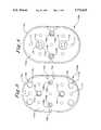
- a conventional hinge 10 for an orthopedic brace having rigid upper and lower arms 12, 14is illustrated.
- the hinge 10dynamically joins the upper and lower arms 12, 14 for rotational pivoting movement thereof.
- the hinge 10includes first and second rigid metal hinge plates 16, 18 that are spaced from the upper and lower arms 12, 14 by friction-reducing plastic washers 20, 22.
- the washers 20, 22slidably engage the upper and lower arms 12, 14 during rotational pivoting movement thereof.
- the conventional hinge 10further includes first and second substantially rigid hinge covers 24, 26 positioned over the first and second hinge plates 16, 18, respectively, to enclose and protect the internal hinge components, as well as to shield the user and others from contact with the internal hinge components.
- the first hinge cover 24has upper and lower slots 28a, 28b formed therein to receive upper and lower flanges 30a, 30b extending from the first hinge plate 16, thereby enabling detachable connection of the first hinge cover 24 to the first hinge plate 16.
- the second hinge cover 26similarly has upper and lower slots 32a, 32b formed therein to receive upper and lower flanges 34a, 34b extending from the second hinge plate 18 facilitating connection of the second hinge cover 26 to the second hinge plate 18.
- the conventional hinge 10also includes a rivet fastener 36 and bushing 38 rotatably coupling an upper portion of the first and second hinge plates 16, 18, washers 20, 22 and second hinge cover 26 to the upper arm 12.
- Another rivet fastener 40 and bushing 42rotatably couples a lower portion of the first and second hinge plates 16, 18, washers 20, 22 and second hinge cover 26 to the lower arm 14.
- the rivet fasteners 38, 40 38, 40also attach a hinge pad holder 44 to the hinge 10.
- the hinge 10is further provided with intermeshing teeth 46, 48 located on adjacent ends of the upper and lower arms 12, 14 to maintain symmetric movement of the upper and lower arms 12, 14 relative to the hinge 10.
- FIG. 1Ban alternate conventional hinge 50 is illustrated, wherein components of the hinge 50 common to the hinge 10 are designated by the same reference characters.
- the conventional hinge 50is substantially identical to the conventional hinge 10, however, the flanges are omitted from the first and second hinge plates 52, 54 of the hinge 50. Instead the first and second hinge covers 56, 58 are permanently affixed to the first and second hinge plates 52, 54, respectively, by gluing.
- orthopedic bracesare commonly worn by athletes and other participants in active endeavors, orthopedic braces are preferably designed to be as unobtrusive as possible while performing their intended function.
- orthopedic bracesare desirably designed to be compact and free of protruding components that could injure or irritate the user of the orthopedic brace or others coming in contact with the user.
- orthopedic bracesare desirably designed to have lower production costs in response to cost sensitivities in the health care industry. Accordingly, it is an object of the present invention to provide a hinge for an orthopedic brace that provides effective rotational pivoting movement of the brace. It is another object of the present invention to provide such a hinge that has diminished size and has relatively smooth exterior surfaces. It is yet another object of the present invention to provide such a hinge having a simplified design that reduces material and assembly costs, thereby reducing the overall cost of the hinge and associated orthopedic brace.
- the present inventionis a hinge for an orthopedic brace, wherein the brace has an upper arm and a lower arm pivotally coupled by the hinge.
- the hingecomprises a first hinge plate having a substantially planar rigid support member with a first side and a second side.
- An inner friction-reducing coveringis positioned on the first side and an outer protective covering is positioned on the second side.
- the inner friction-reducing covering and the outer protective coveringare integrally formed to substantially enclose the support member in a single smooth continuous unitary covering.
- the inner friction-reducing coveringreduces friction between the first hinge plate and the upper and lower arms during pivoting movement of the hinge and the outer protecting covering protects the hinge from external interference during pivoting movement and avoids injury to the user or others contacting the hinge.
- a second hinge plate having substantially the same construction as the first hinge plateis parallely aligned with the first hinge plate and is connected thereto.
- the lower end of the upper arm and the upper end of the lower armare positioned between the first and second hinge plates and are rotatably connected thereto to provide pivotal coupling of the ends.
- each hinge plateis formed from a first material and the unitary covering of the hinge plate is formed from a second material, wherein the friction coefficient of the second material with respect to the lower and upper ends is substantially less than that of the first material with respect to the lower and upper ends.
- the first materialis preferably a metal and the second material is preferably a plastic.
- the hinge plateis preferably formed by an insert molding process, wherein the support member is inserted in a mold and a liquid plastic is injected into the mold around the support member. The liquid plastic is then hardened to a solid plastic forming the unitary covering and the hinge plate is removed from the mold.
- the support membermay be provided with one or more securing bores formed therethrough. The securing bores receive the liquid plastic during the insert molding process.
- the plastic thereinforms integral connective members between the inner and outer coverings upon hardening that secure the unitary covering to the support member.
- FIG. 1Ais a cross-sectional view of a prior art hinge for an orthopedic brace.
- FIG. 1Bis a cross-sectional view of an alternate prior art hinge for an orthopedic brace.
- FIG. 2is a frontal view of an orthopedic brace incorporating the hinges of the present invention.
- FIG. 3is a cross-sectional view of a hinge of FIG. 2.
- FIG. 4is a frontal view of a hinge plate employed in a hinge of FIG. 2.
- FIG. 5is a rear view of the hinge plate employed in a hinge of FIG. 2.
- FIG. 6is a frontal view of an extension limiting device employed in a hinge of FIG. 2.
- FIG. 7is a frontal view of a flexion limiting device employed in a hinge of FIG. 2.
- FIG. 8is a frontal cut away view of a hinge of FIG. 2.
- an orthopedic braceis generally designated 60.
- the orthopedic brace 60 shown and described hereinis a knee brace mountable on the right leg (not shown) of a human body, although it is understood that the skilled artisan can readily adapt the orthopedic brace 60 for mounting on the opposite leg or other joints of the body in accordance with the instant teaching.
- the orthopedic brace 60comprises a plurality of components including a medial hinge 62a and a lateral hinge 62b having substantially the same construction embodying the hinge of the present invention. While the orthopedic brace 60 shown herein has both medial and lateral hinges 62a, 62b, it is apparent to the skilled artisan that the orthopedic brace can alternatively employ a single hinge in either the medial or lateral position.
- the orthopedic brace 60further comprises an upper brace assembly 64 and a lower brace assembly 66 opposingly positioned about the medial and lateral hinges 62a, 62b.
- the upper brace assembly 64includes upper medial and lateral arms 68a, 68b, each having a lower proximate end rotatably coupled by the medial and lateral hinges 62a, 62b, respectively.
- the medial and lateral arms 68a, 68barc in an upwardly anterior direction to form a first upper anterior cross member 70.
- the upper brace assembly 64also includes a second upper anterior cross member 72 located above the first upper anterior cross member 70.
- the upper brace assembly 64extends substantially the length of the upper leg of the user and is retained in removable engagement with the upper leg by means of first and second upper adjustable straps 73, 74.
- the first upper adjustable strap 73includes a pivotable loop fixture 76 rotatably anchored to the second upper anterior cross member 72.
- a self-connecting strap end 78is threaded through the pivotable loop fixture 76 and connected to itself.
- a posterior pad 80provides a cushion between the first upper adjustable strap 73 and the posterior of the user's upper leg.
- An anterior pad 81provides a cushion between the upper anterior cross members 70, 72 and the anterior of the user's upper leg.
- the second upper adjustable strap 74engages the upper medial and lateral arms 68a, 68b below the first upper adjustable strap 73 and includes a pivotable loop fixture 82 and a posterior pad 84.
- the lower brace assembly 66includes lower medial and lateral arms 86a, 86b, each having an upper proximate end rotatably coupled by the medial and lateral hinges 62a, 62b, respectively.
- the medial and lateral arms 86a, 86barc in a downwardly anterior direction to form a first lower anterior cross member 88.
- the lower brace assembly 66also includes a second lower anterior cross member 89 located below the first lower anterior cross member 88.
- the lower brace assembly 66extends substantially the length of the lower leg of the user and is retained in removable engagement with the lower leg by means of first and second lower adjustable straps 90, 91
- the first lower adjustable strap 90engages the lower medial and lateral arms 86a, 86b above the second lower adjustable strap 91 and includes anterior and posterior pads 92, 93.
- the second lower adjustable strap 91includes a pivotable loop fixture 94 rotatably anchored to the second lower anterior cross member 89.
- a self-connecting strap end 95is threaded through the pivotable loop fixture 94 and connected to itself.
- a posterior pad 96provides a cushion between the second lower adjustable strap 91 and the posterior portion of the user's lower leg.
- An anterior pad 98provides a cushion between the lower anterior cross members 88, 89 and the anterior portion of the user's lower leg.
- the lower adjustable straps 90, 91attach the lower brace assembly 66 to the user's lower leg and the upper adjustable straps 73, 74 attach the upper brace assembly to the user's upper leg.
- Medial and lateral hinge pads 100a, 100b retained by medial and lateral hinge pad holders 102a, 102bare further provided to cushion the user's knee condyles from the hinges 62a, 62b.
- the medial and lateral hinge pads 100a, 100b, in association with pads 80, 81, 84, 92, 93, 96, 98improve both the fit and the comfort of the orthopedic brace 60 during use.
- the hinge 62 shown in FIG. 3is identical to the hinges 62a, 62b shown in FIG. 2.
- the hinge 62includes a first hinge plate 108a and a second hinge plate 108b preferably having substantially the same construction.
- the first and second hinge plates 108a, 108bhave a low profile due to a substantially planar configuration.
- the first and second hinge plates 108a, 108binclude substantially planar support members 110a, 110b having outer sides 112a, 112b and inner sides 113a, 113b.
- the support members 110a, 110bare preferably formed from a rigid, high-strength metal such as aluminum or steel.
- the first and second hinge plates 108a, 108bfurther include outer protective coverings 114a, 114b and inner friction-reducing coverings 116a, 116b preferably formed from a high-strength plastic providing a relatively smooth, low-friction surface.
- first and second hinge plates 108a, 108bhave substantially the same construction, their construction is described in further detail below with respect to the first hinge plate 108a. It is understood, however, that this description applies to the second hinge plate 108b as well.
- the outer protective covering 114a and the inner friction-reducing covering 116aare shown to be a single substantially continuous unitary covering integrally formed around and substantially enclosing the support member 110a.
- the outer and inner coverings 114a, 116aare integrally formed around the support member 110a by insert molding the support member 110a within the outer and inner coverings 114a, 116a.
- Insert moldingcomprises placing the support member 110a in a mold and injecting a fluid plastic into the mold to substantially surround the support member 110a.
- a plurality of securing bores 117 formed in the support member 110aare filled with plastic to form connective members 118 during the insert molding process that securely position the outer and inner coverings 114a, 116a relative to the support member 110a.
- the fluid plasticis in place in the mold, it is cured or hardened to a hard solid plastic and the resulting first hinge plate 108a is removed from the mold.
- the upper and lower arms 68, 86have lower and upper ends 119, 120 that are oriented proximal to the knee joint.
- the upper and lower arms 68, 86are attached to the hinge 62 by conventional upper and lower fasteners 121a, 121b, such as the fastening rivets shown here having an identical construction.
- the fasteners 121a, 121beach have a head portion 122, a cylindrical portion 124 positioned within a bushing 126 upon which the upper and lower arms 68, 86 rotate, and a flange portion 128.
- the hinge plate 108aincludes bores 130, 132 in the outer protective covering 114a that provide clearance for the head portion 122 and the flange portion 128 of the fasteners 121a, 121b.
- the head portion 122 and flange portion 128 of the fasteners 121a, 121bare preferably flush with the outer protective covering 114a.
- the upper and lower arms 68, 86preferably include intermeshing teeth 138,140 that meet at a contact point between the lower and upper ends 119, 120.
- the intermeshing teeth 138,140maintain symmetric movement of the upper and lower brace assemblies 64, 66 relative to the hinge 62 in a conventional manner.
- the support member 110ais shown to further include circular bores 142, 144 for receiving the cylindrical portions 124 and bushings 126 of the fasteners 121a, 121b. Bores 146a, 146b are also provided in the midportion of the outer protective covering 114a and the inner friction-reducing covering 116a that, in association with bores 148a, 148b provided in the midportion of the support member 110a, receive a second fastener, such as a threaded screw (not shown), to secure the flexion and extension limiters (not shown) described hereafter. It is noted that the peripheral edge of the support member 110a does not extend fully to the peripheral edge of the first hinge plate 108a. Consequently the outer and inner coverings 114a, 116a define the peripheral edge of the first hinge plate 108a.
- the inner friction-reducing covering 116ais shown to further include bores 146a, 146b, 150, 152 and grooves 154, 156, 158.
- the grooves 154, 156in combination with the bore 146a in the inner friction-reducing covering 116a, the bore 148a in the support member 110a and a fastener, such as a threaded screw (not shown), securely position a flexion limiter that will be described hereafter with reference to FIGS. 7 and 8.
- the groove 158in combination with the bore 146b in the inner friction-reducing covering 116a, the bore 148a in the support member 110a and a fastener, such as a threaded screw (not shown), securely position an extension limiter that will be described hereafter with reference to FIGS. 6 and 8.
- the inner friction-reducing covering 116aalso includes bores 168 formed as a result of the insert molding process.
- the extension limiter 174is illustrated having pins 176a, 176b and a bore 178 that help position and secure the extension limiter 174 between the first and second hinge plates 108a, 108b.
- the pins 176a, 176bextend from the surface of the extension limiter 174 and are aligned with and inserted into the grooves 154, 156 formed in the first and second hinge plates 108a, 108b.
- a fastenersuch as a threaded screw (not shown), is inserted into the bores 146b, 148b in the first and second hinge plates 108a, 108b and the bore 178 in the extension limiter 174.
- the extension limiter 174is inserted and secured between the first and second hinge plates 108a, 108b or is removed as desired.
- first and second arcuate surfaces 180, 182provide clearance for rotary movement of the lower end 119 of the upper brace assembly 64, the upper end 120 of the lower brace assembly 66 and the intermeshing teeth 138, 140.
- the first and second stop surfaces 184a, 184babut anterior arm stop surfaces 188a, 188b of the upper and lower brace assemblies 64, 66 to limit extension of the user's leg.
- Alternate extension limiterscan be provided, wherein the position of the stop surfaces 184a, 184b relative to the pins 176a, 176b differs from that shown to provide increased or decreased extension limits.
- Alternate extension limiterscan also be provided, wherein the position of the arm stop surfaces 188a, 188b differs relative to the upper and lower arms 68a, 68b, 86a, 86b.
- the flexion limiter 194is illustrated having a pin 196 and a bore 198 that help position and secure the flexion limiter 194 between the hinge plates 108a, 108b.
- the pin 196extends from the surface of the flexion limiter 194 and is aligned with and inserted into the grooves 158 formed in the first and second hinge plates 108a, 108b.
- a fastenersuch as a threaded screw (not shown), is inserted into the bores 146a, 148a in the first and second hinge plates 108a, 108b and the bore 198 of the flexion limiter 194.
- first and second arcuate surfaces 200, 202provide clearance for rotary movement of the lower end 119 of the upper brace assembly 64, the upper end 120 of the lower brace assembly 66 and the intermeshing teeth 138, 140.
- the first and second stop surfaces 204a, 204babut posterior arm stop surfaces 206a, 206b on the upper and lower brace assemblies 64, 66 to limit flexion of the user's leg.
- Alternate flexion limiterscan be provided, wherein the position of the stop surfaces 204a, 204b relative to the pin 196 differs from that shown to provide increased or decreased flexion limits.
- a usermounts the orthopedic brace 60 onto the leg and secures the brace 60 with the straps 73, 74, 90 and 91.
- the upper and lower brace assemblies 64, 66rotatably pivot relative to the hinges 62a, 62b.
- the intermeshing gears 138, 140maintain symmetric movement of the upper and lower brace assemblies 64, 66 relative to the hinges 62a, 62b, thereby stabilizing movement of the knee joint.
- the inner friction-reducing coverings 116a, 116bsubstantially reduce friction between upper and lower brace assemblies 64 and 66 and the hinges 62a, 62b to facilitate the rotational pivoting movement of the brace 60.
- the inner friction-reducing coverings 116a, 116bpreferably have a lower friction coefficient with respect to the ends of the arms 119, 120 than that of the support members 110a, 110b.
- the outer protective coverings 114a, 114bprotect the hinges 62a, 62b from external interferences and provide smooth outer hinge surfaces that do not abrade the user or others contacting the hinges 62a, 62b during use of the brace 60.
- the hinge of the present inventionachieves a reduced profile by integrating the internal support members and coverings while maintaining strength and functionality at a decreased cost.
- hingefor an orthopedic brace shown and disclosed herein is fully capable of obtaining the objects and providing the advantages stated herein, it is understood that the hinge is merely illustrative of presently preferred embodiments of the invention and that other embodiments are possible within the scope of the present invention.
Landscapes
- Health & Medical Sciences (AREA)
- Nursing (AREA)
- Orthopedic Medicine & Surgery (AREA)
- Engineering & Computer Science (AREA)
- Biomedical Technology (AREA)
- Heart & Thoracic Surgery (AREA)
- Vascular Medicine (AREA)
- Life Sciences & Earth Sciences (AREA)
- Animal Behavior & Ethology (AREA)
- General Health & Medical Sciences (AREA)
- Public Health (AREA)
- Veterinary Medicine (AREA)
- Orthopedics, Nursing, And Contraception (AREA)
Abstract
Description
Claims (18)
Priority Applications (1)
| Application Number | Priority Date | Filing Date | Title |
|---|---|---|---|
| US08/656,088US5772618A (en) | 1996-05-31 | 1996-05-31 | Hinge for an orthopedic brace |
Applications Claiming Priority (1)
| Application Number | Priority Date | Filing Date | Title |
|---|---|---|---|
| US08/656,088US5772618A (en) | 1996-05-31 | 1996-05-31 | Hinge for an orthopedic brace |
Publications (1)
| Publication Number | Publication Date |
|---|---|
| US5772618Atrue US5772618A (en) | 1998-06-30 |
Family
ID=24631569
Family Applications (1)
| Application Number | Title | Priority Date | Filing Date |
|---|---|---|---|
| US08/656,088Expired - LifetimeUS5772618A (en) | 1996-05-31 | 1996-05-31 | Hinge for an orthopedic brace |
Country Status (1)
| Country | Link |
|---|---|
| US (1) | US5772618A (en) |
Cited By (62)
| Publication number | Priority date | Publication date | Assignee | Title |
|---|---|---|---|---|
| DE29902609U1 (en) | 1999-02-08 | 1999-07-15 | Fior & Gentz GmbH Gesellschaft für Entwicklung und Vertrieb von orthopädietechnischen Systemen mbH, 21335 Lüneburg | Multifunctional orthotic joint |
| US6045520A (en)* | 1998-03-16 | 2000-04-04 | Cramer Products, Inc. | Articulated splint |
| USD448484S1 (en) | 2000-11-30 | 2001-09-25 | Scott Orthotic Labs, Inc. | Ankle joint for an ankle foot orthosis |
| US20030051470A1 (en)* | 2001-09-14 | 2003-03-20 | David Maddock | Control system for hydraulic equipment attachments |
| US20030153853A1 (en)* | 2002-02-15 | 2003-08-14 | Houser Guy M. | Bicentric hinge for use in a brace |
| WO2003068115A1 (en)* | 2002-02-11 | 2003-08-21 | Dj Orthopedics, Llc | Brace hinge with telescoping condyle pad |
| US20040049140A1 (en)* | 2002-09-11 | 2004-03-11 | Doty Alexis E. | Lockable Hinge |
| US20040267177A1 (en)* | 2003-06-30 | 2004-12-30 | Houser Guy M. | Knee brace with dynamic counterforce |
| US20050143797A1 (en)* | 2003-07-18 | 2005-06-30 | Thermotek, Inc. | Compression sequenced thermal therapy system |
| US20050273025A1 (en)* | 2004-05-19 | 2005-12-08 | Houser Guy M | Braces having an assembly for exerting a manually adjustable force on a limb of a user |
| US7059329B2 (en) | 2000-09-22 | 2006-06-13 | Breg, Inc. | Knee brace providing dynamic tracking of the patello-femoral joint |
| WO2006078428A2 (en) | 2005-01-22 | 2006-07-27 | Breg, Inc. | Frame for an orthopedic brace including offset hinges |
| US20070100265A1 (en)* | 2003-12-12 | 2007-05-03 | The Regents Of The University Of Colorado, A Body Corporate | Non-surgical correcting abnormal knee loading |
| US20070112401A1 (en)* | 2005-10-14 | 2007-05-17 | Niran Balachandran | Critical care thermal therapy method and system |
| US20070244419A1 (en)* | 2006-04-13 | 2007-10-18 | Mason Bradley R | Rotational hinge assembly for a knee brace having an osteoarthritis treatment function |
| EP1854434A1 (en)* | 2006-05-09 | 2007-11-14 | Otto Bock HealthCare IP GmbH & Co. KG | Jointed orthesis |
| WO2008039933A1 (en)* | 2006-09-29 | 2008-04-03 | Djo, Llc | Quiet flexion/extension stop for orthopedic brace and orthopedic brace incorporating a quiet flexion/extension stop |
| US20080249448A1 (en)* | 2007-04-06 | 2008-10-09 | Stevenson Craig G | Cable-based orthopedic bracing system |
| US7488300B2 (en) | 2002-02-15 | 2009-02-10 | Thusane | Bicentric hinge for use in a brace |
| US20090109622A1 (en)* | 2004-08-12 | 2009-04-30 | Parish Overton L | Thermal control system for rack mounting |
| US8100956B2 (en) | 2006-05-09 | 2012-01-24 | Thermotek, Inc. | Method of and system for thermally augmented wound care oxygenation |
| US8128672B2 (en) | 2006-05-09 | 2012-03-06 | Thermotek, Inc. | Wound care method and system with one or both of vacuum-light therapy and thermally augmented oxygenation |
| USD662214S1 (en) | 2007-04-10 | 2012-06-19 | Thermotek, Inc. | Circumferential leg wrap |
| EP2491896A1 (en) | 2011-02-24 | 2012-08-29 | Breg, Inc. | Frame for an orthopedic brace having a truss structure and an associated strapping system |
| USD679023S1 (en) | 2004-07-19 | 2013-03-26 | Thermotek, Inc. | Foot wrap |
| US8574278B2 (en) | 2006-05-09 | 2013-11-05 | Thermotek, Inc. | Wound care method and system with one or both of vacuum-light therapy and thermally augmented oxygenation |
| EP2679203A1 (en) | 2012-06-27 | 2014-01-01 | Breg, Inc. | Anti-migration pad for an orthopedic brace |
| US8758419B1 (en) | 2008-01-31 | 2014-06-24 | Thermotek, Inc. | Contact cooler for skin cooling applications |
| US8778005B2 (en) | 2003-07-18 | 2014-07-15 | Thermotek, Inc. | Method and system for thermal and compression therapy relative to the prevention of deep vein thrombosis |
| USD716000S1 (en) | 2012-08-14 | 2014-10-21 | Medical Technology Inc. | Sports leg protector |
| US9021614B2 (en) | 2011-02-18 | 2015-05-05 | Medical Techology, Inc. | Leg protector for sports activities |
| US9119705B2 (en) | 1998-06-08 | 2015-09-01 | Thermotek, Inc. | Method and system for thermal and compression therapy relative to the prevention of deep vein thrombosis |
| EP2959869A1 (en) | 2014-06-28 | 2015-12-30 | Breg, Inc. | Orthopedic brace applying variable tension during joint range of motion activity |
| FR3023707A1 (en)* | 2014-07-15 | 2016-01-22 | Gibaud | ENSEMBLE TO BE PLACED ON A MEMBER OF A PERSON, COMPRISING AN ARTICULATION DEVICE AND MEANS FOR LIMITING THE ANGLE OF THE JOINT |
| US20160143763A1 (en)* | 2014-11-20 | 2016-05-26 | Ossur Iceland Ehf | Polymeric polycentric hinge |
| ITUB20152729A1 (en)* | 2015-07-31 | 2017-01-31 | Orthoservice Ag | ARTICULATED ROD WITH FLEXIBLE ADJUSTABLE POLYCENTRIC JOINT IN EXTENSION. |
| DE102015217205A1 (en)* | 2015-09-09 | 2017-03-09 | Bauerfeind Ag | Schwenklimitierbares biaxial joint |
| US9615967B2 (en) | 2010-12-30 | 2017-04-11 | Coolsystems, Inc. | Reinforced therapeutic wrap and method |
| US9615955B2 (en) | 2011-04-21 | 2017-04-11 | Breg, Inc. | Orthopedic knee brace with dynamically changing medial and lateral hinges |
| US9669233B2 (en) | 2013-11-11 | 2017-06-06 | Thermotek, Inc. | Method and system for wound care |
| US20170340471A1 (en)* | 2016-05-31 | 2017-11-30 | United Surgical, Inc. | Flexion and extension range limiting hinge for an orthopedic brace |
| US9943437B2 (en) | 2009-10-22 | 2018-04-17 | Coolsystems, Inc. | Temperature and flow control methods in a thermal therapy device |
| US9980844B2 (en) | 2007-02-13 | 2018-05-29 | Coolsystems, Inc. | Flexible joint wrap |
| US10016583B2 (en) | 2013-03-11 | 2018-07-10 | Thermotek, Inc. | Wound care and infusion method and system utilizing a thermally-treated therapeutic agent |
| US10149927B2 (en) | 2012-04-24 | 2018-12-11 | Thermotek, Inc. | Method and system for therapeutic use of ultra-violet light |
| US10300180B1 (en) | 2013-03-11 | 2019-05-28 | Thermotek, Inc. | Wound care and infusion method and system utilizing a therapeutic agent |
| US10456320B2 (en) | 2013-10-01 | 2019-10-29 | Coolsystems, Inc. | Hand and foot wraps |
| US10463565B2 (en) | 2011-06-17 | 2019-11-05 | Coolsystems, Inc. | Adjustable patient therapy device |
| US10512587B2 (en) | 2011-07-27 | 2019-12-24 | Thermotek, Inc. | Method and apparatus for scalp thermal treatment |
| WO2020123583A1 (en)* | 2018-12-11 | 2020-06-18 | Ossur Iceland Ehf | Hinge having a rotation-stop lock |
| US10765785B2 (en) | 2004-07-19 | 2020-09-08 | Thermotek, Inc. | Wound care and infusion method and system utilizing a therapeutic agent |
| US10859295B2 (en) | 2016-04-13 | 2020-12-08 | ZeoThermal Technologies, LLC | Cooling and heating platform |
| IT201900014856A1 (en)* | 2019-08-20 | 2021-02-20 | Tenortho S R L Unipersonale | JOINT FOR ARTICULATION |
| US11013635B2 (en) | 2004-05-17 | 2021-05-25 | Coolsystems, Inc. | Modular apparatus for therapy of an animate body |
| US11096803B2 (en) | 2016-12-06 | 2021-08-24 | Ossur Iceland Ehf | Movable joint for use in a prosthetic or orthopedic system |
| US11458032B2 (en) | 2014-06-28 | 2022-10-04 | Sports Medicine Sciences, LLC | Anatomical brace for dynamically stabilizing the patella during knee articulation so as to address patella tracking error |
| US11672693B2 (en) | 2014-08-05 | 2023-06-13 | Avent, Inc. | Integrated multisectional heat exchanger |
| US11737903B2 (en) | 2017-07-28 | 2023-08-29 | Sports Medicine Sciences, LLC | Anatomical brace for dynamically stabilizing the elbow |
| US20230293329A1 (en)* | 2016-06-24 | 2023-09-21 | Djo, Llc | Brace hinge with telescoping pad |
| US12011381B2 (en) | 2014-06-28 | 2024-06-18 | Sports Medicine Sciences, LLC | Anatomical brace for dynamically stabilizing the patella during knee articulation so as to address patella tracking error |
| US12178729B2 (en) | 2019-03-26 | 2024-12-31 | Ossur Iceland Ehf | Hinge assembly for an orthopedic device |
| US12263111B2 (en) | 2018-12-20 | 2025-04-01 | Djo, Llc | Brace limiting range of motion and method of using same |
Citations (10)
| Publication number | Priority date | Publication date | Assignee | Title |
|---|---|---|---|---|
| US4493316A (en)* | 1983-03-10 | 1985-01-15 | Donjoy, Inc. | Articulating knee stabilizer |
| US4620532A (en)* | 1983-09-26 | 1986-11-04 | Lenox Hill Brace Shop, Inc. | Adjustment device for an articulated joint brace |
| US4691697A (en)* | 1985-04-05 | 1987-09-08 | Strom-Tec, Inc. | Knee support |
| US4697583A (en)* | 1985-01-29 | 1987-10-06 | Don Joy Orthopedic, Inc. | Four-point anterior cruciate ligament brace |
| US4991571A (en)* | 1988-09-08 | 1991-02-12 | Kausek James H | Modular knee brace for control of ligament instability |
| US5038765A (en)* | 1989-08-14 | 1991-08-13 | Protectair Limited | Orthopaedic bipivotal hinge and pivot control system therefor |
| US5062858A (en)* | 1989-05-30 | 1991-11-05 | Vanden Broeck | Connecting device for two members of an artificial joint |
| US5168865A (en)* | 1991-05-06 | 1992-12-08 | Orthopedic Systems, Inc. | Knee brace with pivot lock |
| US5356370A (en)* | 1993-09-09 | 1994-10-18 | Generation Ii Orthotics Inc. | Antifriction mechanical joint for an orthopedic knee brace |
| US5586970A (en)* | 1995-01-23 | 1996-12-24 | Orthopedic Technology, Inc. | Articulating adjustabe condylar pad for knee brace |
- 1996
- 1996-05-31USUS08/656,088patent/US5772618A/ennot_activeExpired - Lifetime
Patent Citations (10)
| Publication number | Priority date | Publication date | Assignee | Title |
|---|---|---|---|---|
| US4493316A (en)* | 1983-03-10 | 1985-01-15 | Donjoy, Inc. | Articulating knee stabilizer |
| US4620532A (en)* | 1983-09-26 | 1986-11-04 | Lenox Hill Brace Shop, Inc. | Adjustment device for an articulated joint brace |
| US4697583A (en)* | 1985-01-29 | 1987-10-06 | Don Joy Orthopedic, Inc. | Four-point anterior cruciate ligament brace |
| US4691697A (en)* | 1985-04-05 | 1987-09-08 | Strom-Tec, Inc. | Knee support |
| US4991571A (en)* | 1988-09-08 | 1991-02-12 | Kausek James H | Modular knee brace for control of ligament instability |
| US5062858A (en)* | 1989-05-30 | 1991-11-05 | Vanden Broeck | Connecting device for two members of an artificial joint |
| US5038765A (en)* | 1989-08-14 | 1991-08-13 | Protectair Limited | Orthopaedic bipivotal hinge and pivot control system therefor |
| US5168865A (en)* | 1991-05-06 | 1992-12-08 | Orthopedic Systems, Inc. | Knee brace with pivot lock |
| US5356370A (en)* | 1993-09-09 | 1994-10-18 | Generation Ii Orthotics Inc. | Antifriction mechanical joint for an orthopedic knee brace |
| US5586970A (en)* | 1995-01-23 | 1996-12-24 | Orthopedic Technology, Inc. | Articulating adjustabe condylar pad for knee brace |
Cited By (110)
| Publication number | Priority date | Publication date | Assignee | Title |
|---|---|---|---|---|
| US6045520A (en)* | 1998-03-16 | 2000-04-04 | Cramer Products, Inc. | Articulated splint |
| US9119705B2 (en) | 1998-06-08 | 2015-09-01 | Thermotek, Inc. | Method and system for thermal and compression therapy relative to the prevention of deep vein thrombosis |
| US9877864B2 (en) | 1998-06-08 | 2018-01-30 | Thermotek, Inc. | Compression sequenced thermal therapy system |
| US9433525B2 (en) | 1998-06-08 | 2016-09-06 | Thermotek, Inc. | Compression sequenced thermal therapy system |
| US10507131B2 (en) | 1998-06-08 | 2019-12-17 | Thermotek, Inc. | Method and system for thermal and compression therapy relative to the prevention of deep vein thrombosis |
| US9180041B2 (en) | 1998-06-08 | 2015-11-10 | Thermotek, Inc. | Compression sequenced thermal therapy system |
| DE29902609U1 (en) | 1999-02-08 | 1999-07-15 | Fior & Gentz GmbH Gesellschaft für Entwicklung und Vertrieb von orthopädietechnischen Systemen mbH, 21335 Lüneburg | Multifunctional orthotic joint |
| US7059329B2 (en) | 2000-09-22 | 2006-06-13 | Breg, Inc. | Knee brace providing dynamic tracking of the patello-femoral joint |
| USD448484S1 (en) | 2000-11-30 | 2001-09-25 | Scott Orthotic Labs, Inc. | Ankle joint for an ankle foot orthosis |
| US20030051470A1 (en)* | 2001-09-14 | 2003-03-20 | David Maddock | Control system for hydraulic equipment attachments |
| WO2003068115A1 (en)* | 2002-02-11 | 2003-08-21 | Dj Orthopedics, Llc | Brace hinge with telescoping condyle pad |
| US6752775B2 (en)* | 2002-02-11 | 2004-06-22 | Dj Orthopedics, Llc | Brace hinge with telescoping condyle pad |
| US20030153853A1 (en)* | 2002-02-15 | 2003-08-14 | Houser Guy M. | Bicentric hinge for use in a brace |
| US7488300B2 (en) | 2002-02-15 | 2009-02-10 | Thusane | Bicentric hinge for use in a brace |
| US6969363B2 (en)* | 2002-02-15 | 2005-11-29 | Thuasne | Bicentric hinge for use in a brace |
| US7235058B2 (en)* | 2002-09-11 | 2007-06-26 | Djo, Llc | Lockable hinge |
| US20080077065A1 (en)* | 2002-09-11 | 2008-03-27 | Djo, Llc | Lockable hinge |
| US20040049140A1 (en)* | 2002-09-11 | 2004-03-11 | Doty Alexis E. | Lockable Hinge |
| WO2004024040A3 (en)* | 2002-09-11 | 2004-05-21 | Dj Orthopedics Dev Corp | Lockable hinge |
| US7722555B2 (en)* | 2002-09-11 | 2010-05-25 | Djo, Llc | Lockable hinge |
| US7150721B2 (en) | 2003-06-30 | 2006-12-19 | Thuasne | Knee brace with dynamic counterforce |
| US20040267177A1 (en)* | 2003-06-30 | 2004-12-30 | Houser Guy M. | Knee brace with dynamic counterforce |
| US9192539B2 (en) | 2003-07-18 | 2015-11-24 | Thermotek, Inc. | Method and system for thermal and compression therapy relative to the prevention of deep vein thrombosis |
| US10507140B2 (en) | 2003-07-18 | 2019-12-17 | Thermotek, Inc. | Wound care method and system with one or both of vacuum-light therapy and thermally augmented oxygenation |
| US8425580B2 (en) | 2003-07-18 | 2013-04-23 | Thermotek, Inc. | Method of and system for thermally augmented wound care oxygenation |
| US8753383B2 (en) | 2003-07-18 | 2014-06-17 | Thermotek, Inc. | Compression sequenced thermal therapy system |
| US9616210B2 (en) | 2003-07-18 | 2017-04-11 | Thermotek, Inc. | Wound care method and system with one or both of vacuum-light therapy and thermally augmented oxygenation |
| US20050143797A1 (en)* | 2003-07-18 | 2005-06-30 | Thermotek, Inc. | Compression sequenced thermal therapy system |
| US8778005B2 (en) | 2003-07-18 | 2014-07-15 | Thermotek, Inc. | Method and system for thermal and compression therapy relative to the prevention of deep vein thrombosis |
| US20070100265A1 (en)* | 2003-12-12 | 2007-05-03 | The Regents Of The University Of Colorado, A Body Corporate | Non-surgical correcting abnormal knee loading |
| US7435234B2 (en) | 2003-12-12 | 2008-10-14 | The Regents Of The University Of Colorado, A Body Corporate | Non-surgical correcting abnormal knee loading |
| US11013635B2 (en) | 2004-05-17 | 2021-05-25 | Coolsystems, Inc. | Modular apparatus for therapy of an animate body |
| US20050273025A1 (en)* | 2004-05-19 | 2005-12-08 | Houser Guy M | Braces having an assembly for exerting a manually adjustable force on a limb of a user |
| USD679023S1 (en) | 2004-07-19 | 2013-03-26 | Thermotek, Inc. | Foot wrap |
| US10765785B2 (en) | 2004-07-19 | 2020-09-08 | Thermotek, Inc. | Wound care and infusion method and system utilizing a therapeutic agent |
| US8940034B2 (en) | 2004-07-19 | 2015-01-27 | Thermotek, Inc. | Wound care method and system with one or both of vacuum-light therapy and thermally augmented oxygenation |
| US20090109622A1 (en)* | 2004-08-12 | 2009-04-30 | Parish Overton L | Thermal control system for rack mounting |
| US8248798B2 (en) | 2004-08-12 | 2012-08-21 | Thermotek, Inc. | Thermal control system for rack mounting |
| US7804686B2 (en) | 2004-08-12 | 2010-09-28 | Thermotek, Inc. | Thermal control system for rack mounting |
| WO2006078428A2 (en) | 2005-01-22 | 2006-07-27 | Breg, Inc. | Frame for an orthopedic brace including offset hinges |
| US7909861B2 (en) | 2005-10-14 | 2011-03-22 | Thermotek, Inc. | Critical care thermal therapy method and system |
| US20070112401A1 (en)* | 2005-10-14 | 2007-05-17 | Niran Balachandran | Critical care thermal therapy method and system |
| US20070244419A1 (en)* | 2006-04-13 | 2007-10-18 | Mason Bradley R | Rotational hinge assembly for a knee brace having an osteoarthritis treatment function |
| US7485103B2 (en)* | 2006-04-13 | 2009-02-03 | Breg, Inc. | Rotational hinge assembly for a knee brace having an osteoarthritis treatment function |
| US10507311B2 (en) | 2006-05-09 | 2019-12-17 | Thermotek, Inc. | Wound care method and system with one or both of vacuum-light therapy and thermally augmented oxygenation |
| EP1854434A1 (en)* | 2006-05-09 | 2007-11-14 | Otto Bock HealthCare IP GmbH & Co. KG | Jointed orthesis |
| US8128672B2 (en) | 2006-05-09 | 2012-03-06 | Thermotek, Inc. | Wound care method and system with one or both of vacuum-light therapy and thermally augmented oxygenation |
| US20070276305A1 (en)* | 2006-05-09 | 2007-11-29 | Otto Bock Healthcare Ip Gmbh & Co. Kg | Joint orthosis |
| US8100956B2 (en) | 2006-05-09 | 2012-01-24 | Thermotek, Inc. | Method of and system for thermally augmented wound care oxygenation |
| US9950148B2 (en) | 2006-05-09 | 2018-04-24 | Thermotek, Inc. | Wound care method and system with one or both of vacuum-light therapy and thermally augmented oxygenation |
| US8574278B2 (en) | 2006-05-09 | 2013-11-05 | Thermotek, Inc. | Wound care method and system with one or both of vacuum-light therapy and thermally augmented oxygenation |
| US8142486B2 (en) | 2006-05-09 | 2012-03-27 | Thermotek, Inc. | Wound care method and system with one or both of vacuum-light therapy and thermally augmented oxygenation |
| US8632576B2 (en) | 2006-05-09 | 2014-01-21 | Thermotek, Inc. | Wound care method and system with one or both of vacuum-light therapy and thermally augmented oxygenation |
| CN101069666B (en)* | 2006-05-09 | 2012-05-16 | 奥托·博克保健有限公司 | Joint orthosis |
| US7887496B2 (en)* | 2006-05-09 | 2011-02-15 | Otto Bock Healthcare Ip Gmbh & Co. Kg | Joint orthosis |
| WO2008039933A1 (en)* | 2006-09-29 | 2008-04-03 | Djo, Llc | Quiet flexion/extension stop for orthopedic brace and orthopedic brace incorporating a quiet flexion/extension stop |
| US9980844B2 (en) | 2007-02-13 | 2018-05-29 | Coolsystems, Inc. | Flexible joint wrap |
| US20080249448A1 (en)* | 2007-04-06 | 2008-10-09 | Stevenson Craig G | Cable-based orthopedic bracing system |
| US8128587B2 (en) | 2007-04-06 | 2012-03-06 | Sp Design, Llc | Cable-based orthopedic bracing system |
| US7806842B2 (en) | 2007-04-06 | 2010-10-05 | Sp Design, Llc | Cable-based orthopedic bracing system |
| US20110046528A1 (en)* | 2007-04-06 | 2011-02-24 | Sp Design, Llc | Cable-based orthopedic bracing system |
| USD662212S1 (en) | 2007-04-10 | 2012-06-19 | Thermotek, Inc. | Butterfly wrap |
| USD664260S1 (en) | 2007-04-10 | 2012-07-24 | Thermotek, Inc. | Calf wrap |
| USD662213S1 (en) | 2007-04-10 | 2012-06-19 | Thermotek, Inc. | Knee wrap |
| USD683042S1 (en) | 2007-04-10 | 2013-05-21 | Thermotek, Inc. | Calf wrap |
| USD662214S1 (en) | 2007-04-10 | 2012-06-19 | Thermotek, Inc. | Circumferential leg wrap |
| US8758419B1 (en) | 2008-01-31 | 2014-06-24 | Thermotek, Inc. | Contact cooler for skin cooling applications |
| US9943437B2 (en) | 2009-10-22 | 2018-04-17 | Coolsystems, Inc. | Temperature and flow control methods in a thermal therapy device |
| US9615967B2 (en) | 2010-12-30 | 2017-04-11 | Coolsystems, Inc. | Reinforced therapeutic wrap and method |
| US11547625B2 (en) | 2010-12-30 | 2023-01-10 | Avent, Inc. | Reinforced therapeutic wrap and method |
| US9021614B2 (en) | 2011-02-18 | 2015-05-05 | Medical Techology, Inc. | Leg protector for sports activities |
| EP2491896A1 (en) | 2011-02-24 | 2012-08-29 | Breg, Inc. | Frame for an orthopedic brace having a truss structure and an associated strapping system |
| US8419670B2 (en) | 2011-02-24 | 2013-04-16 | Breg, Inc. | Frame for an orthopedic brace having a truss structure and an associated strapping system |
| US9615955B2 (en) | 2011-04-21 | 2017-04-11 | Breg, Inc. | Orthopedic knee brace with dynamically changing medial and lateral hinges |
| US10463565B2 (en) | 2011-06-17 | 2019-11-05 | Coolsystems, Inc. | Adjustable patient therapy device |
| US10512587B2 (en) | 2011-07-27 | 2019-12-24 | Thermotek, Inc. | Method and apparatus for scalp thermal treatment |
| US10149927B2 (en) | 2012-04-24 | 2018-12-11 | Thermotek, Inc. | Method and system for therapeutic use of ultra-violet light |
| EP2679203A1 (en) | 2012-06-27 | 2014-01-01 | Breg, Inc. | Anti-migration pad for an orthopedic brace |
| USD716000S1 (en) | 2012-08-14 | 2014-10-21 | Medical Technology Inc. | Sports leg protector |
| US10918843B2 (en) | 2013-03-11 | 2021-02-16 | Thermotek, Inc. | Wound care and infusion method and system utilizing a thermally-treated therapeutic agent |
| US10016583B2 (en) | 2013-03-11 | 2018-07-10 | Thermotek, Inc. | Wound care and infusion method and system utilizing a thermally-treated therapeutic agent |
| US10300180B1 (en) | 2013-03-11 | 2019-05-28 | Thermotek, Inc. | Wound care and infusion method and system utilizing a therapeutic agent |
| US10456320B2 (en) | 2013-10-01 | 2019-10-29 | Coolsystems, Inc. | Hand and foot wraps |
| US9669233B2 (en) | 2013-11-11 | 2017-06-06 | Thermotek, Inc. | Method and system for wound care |
| US10272258B2 (en) | 2013-11-11 | 2019-04-30 | Thermotek, Inc. | Method and system for wound care |
| US12011381B2 (en) | 2014-06-28 | 2024-06-18 | Sports Medicine Sciences, LLC | Anatomical brace for dynamically stabilizing the patella during knee articulation so as to address patella tracking error |
| US11458032B2 (en) | 2014-06-28 | 2022-10-04 | Sports Medicine Sciences, LLC | Anatomical brace for dynamically stabilizing the patella during knee articulation so as to address patella tracking error |
| EP2959869A1 (en) | 2014-06-28 | 2015-12-30 | Breg, Inc. | Orthopedic brace applying variable tension during joint range of motion activity |
| FR3023707A1 (en)* | 2014-07-15 | 2016-01-22 | Gibaud | ENSEMBLE TO BE PLACED ON A MEMBER OF A PERSON, COMPRISING AN ARTICULATION DEVICE AND MEANS FOR LIMITING THE ANGLE OF THE JOINT |
| US11672693B2 (en) | 2014-08-05 | 2023-06-13 | Avent, Inc. | Integrated multisectional heat exchanger |
| US20160143763A1 (en)* | 2014-11-20 | 2016-05-26 | Ossur Iceland Ehf | Polymeric polycentric hinge |
| US9668903B2 (en)* | 2014-11-20 | 2017-06-06 | Ossur Iceland Ehf | Polymeric polycentric hinge |
| ITUB20152729A1 (en)* | 2015-07-31 | 2017-01-31 | Orthoservice Ag | ARTICULATED ROD WITH FLEXIBLE ADJUSTABLE POLYCENTRIC JOINT IN EXTENSION. |
| DE102015217205A1 (en)* | 2015-09-09 | 2017-03-09 | Bauerfeind Ag | Schwenklimitierbares biaxial joint |
| US11123211B2 (en) | 2015-09-09 | 2021-09-21 | Bauerfeind Ag | Pivoting-limitable biaxial joint |
| US10859295B2 (en) | 2016-04-13 | 2020-12-08 | ZeoThermal Technologies, LLC | Cooling and heating platform |
| US20170340471A1 (en)* | 2016-05-31 | 2017-11-30 | United Surgical, Inc. | Flexion and extension range limiting hinge for an orthopedic brace |
| EP3463207A4 (en)* | 2016-05-31 | 2020-03-04 | United Surgical, Inc. | Flexion and extension range limiting hinge for an orthopedic brace |
| WO2017210212A1 (en) | 2016-05-31 | 2017-12-07 | United Surgical, Inc. | Flexion and extension range limiting hinge for an orthopedic brace |
| US10758392B2 (en)* | 2016-05-31 | 2020-09-01 | United Surgical, Inc. | Flexion and extension range limiting hinge for an orthopedic brace |
| AU2017273450B2 (en)* | 2016-05-31 | 2021-12-09 | United Surgical, Llc | Flexion and extension range limiting hinge for an orthopedic brace |
| US20230293329A1 (en)* | 2016-06-24 | 2023-09-21 | Djo, Llc | Brace hinge with telescoping pad |
| US11096803B2 (en) | 2016-12-06 | 2021-08-24 | Ossur Iceland Ehf | Movable joint for use in a prosthetic or orthopedic system |
| US11737903B2 (en) | 2017-07-28 | 2023-08-29 | Sports Medicine Sciences, LLC | Anatomical brace for dynamically stabilizing the elbow |
| US12290462B2 (en) | 2017-07-28 | 2025-05-06 | Sports Medicine Sciences, LLC | Anatomical brace for dynamically stabilizing the elbow |
| WO2020123583A1 (en)* | 2018-12-11 | 2020-06-18 | Ossur Iceland Ehf | Hinge having a rotation-stop lock |
| US12263111B2 (en) | 2018-12-20 | 2025-04-01 | Djo, Llc | Brace limiting range of motion and method of using same |
| US12178729B2 (en) | 2019-03-26 | 2024-12-31 | Ossur Iceland Ehf | Hinge assembly for an orthopedic device |
| IT201900014856A1 (en)* | 2019-08-20 | 2021-02-20 | Tenortho S R L Unipersonale | JOINT FOR ARTICULATION |
| EP3782590A1 (en)* | 2019-08-20 | 2021-02-24 | Tenortho S.r.l. Unipersonale | Joint for hinged braces |
Similar Documents
| Publication | Publication Date | Title |
|---|---|---|
| US5772618A (en) | Hinge for an orthopedic brace | |
| US5807294A (en) | Adjustable hinge assembly for an osteoarthritic knee brace | |
| US10772387B2 (en) | Configurable subshell components in orthopedic devices | |
| US7059329B2 (en) | Knee brace providing dynamic tracking of the patello-femoral joint | |
| JP4792470B2 (en) | Orthopedic orthosis frame with offset hinge | |
| US11253384B2 (en) | Orthopedic device, strap system and method for securing the same | |
| AU2003209124B2 (en) | Brace hinge with telescoping condyle pad | |
| US4732143A (en) | Selectable extension stop for a polycentric hinge | |
| US4572170A (en) | Preventive knee brace | |
| US7060045B2 (en) | Orthosis providing dynamic tracking of the patello-femoral joint | |
| US11712359B2 (en) | Connector for an orthopedic device | |
| EP2114322B1 (en) | Orthopedic brace and component for use therewith | |
| CA1300317C (en) | Orthosis for stabilizing a joint, preferably a knee-joint | |
| JP2575524B2 (en) | Limb support / fixer | |
| US11850175B2 (en) | Orthopedic device, strap system and method for securing the same | |
| CA2431228A1 (en) | Orthopedic brace having length-adjustable supports | |
| US20030060745A1 (en) | Knee brace hinge deflector | |
| US20250144265A1 (en) | Multi-component frame for use in an orthopedic device | |
| EP2858607B1 (en) | Orthopedic device and components thereof | |
| EP3731788B1 (en) | Orthopedic device, strap system and method for securing the same | |
| WO2021178743A1 (en) | Strap attachment and orthopedic device using the same | |
| AU2002327603A1 (en) | Knee brace hinge deflector |
Legal Events
| Date | Code | Title | Description |
|---|---|---|---|
| AS | Assignment | Owner name:BREG, INC., CALIFORNIA Free format text:ASSIGNMENT OF ASSIGNORS INTEREST;ASSIGNORS:MASON, BRADLEY R.;MASON, JEFFREY T.;REEL/FRAME:008019/0337 Effective date:19960531 | |
| STCF | Information on status: patent grant | Free format text:PATENTED CASE | |
| AS | Assignment | Owner name:SANWA BANK CALIFORNIA, CALIFORNIA Free format text:SECURITY INTEREST;ASSIGNOR:BREG, INC.;REEL/FRAME:010804/0703 Effective date:20000425 | |
| FPAY | Fee payment | Year of fee payment:4 | |
| REMI | Maintenance fee reminder mailed | ||
| AS | Assignment | Owner name:BREG, INC., CALIFORNIA Free format text:RELEASE BY SECURED PARTY;ASSIGNOR:BANK OF THE WEST (AS SUCCESSOR IN INTEREST TO SANWA BANK CALIFORNIA);REEL/FRAME:014178/0897 Effective date:20031209 | |
| AS | Assignment | Owner name:WACHOVIA BANK, NATIONAL ASSOCIATION, AS ADMINISTRA Free format text:NOTICE OF GRANT OF SECURITY INTEREST;ASSIGNOR:BREG INC.;REEL/FRAME:014402/0181 Effective date:20031230 | |
| FEPP | Fee payment procedure | Free format text:PAT HOLDER NO LONGER CLAIMS SMALL ENTITY STATUS, ENTITY STATUS SET TO UNDISCOUNTED (ORIGINAL EVENT CODE: STOL); ENTITY STATUS OF PATENT OWNER: LARGE ENTITY | |
| FPAY | Fee payment | Year of fee payment:8 | |
| AS | Assignment | Owner name:BREG, INC., CALIFORNIA Free format text:TERMINATION OF SECURITY INTEREST;ASSIGNOR:WACHOVIA BANK, NATIONAL ASSOCIATION, AS ADMINISTRATIVE AGENT;REEL/FRAME:017596/0625 Effective date:20060501 | |
| AS | Assignment | Owner name:WACHOVIA BANK, NATIONAL ASSOCIATION, AS ADMINISTRA Free format text:NOTICE OF GRANT OF SECURITY INTEREST;ASSIGNOR:BREG INC.;REEL/FRAME:018362/0602 Effective date:20060922 | |
| FPAY | Fee payment | Year of fee payment:12 | |
| AS | Assignment | Owner name:BREG INC., CALIFORNIA Free format text:TERMINATION OF SECURITY INTEREST IN PATENTS;ASSIGNOR:WELLS FARGO BANK, NATIONAL ASSOCIATION, SUCCESSOR-BY-MERGER TO WACHOVIA BANK, NATIONAL ASSOCIATION, AS ADMINISTRATIVE AGENT;REEL/FRAME:025150/0572 Effective date:20100827 | |
| AS | Assignment | Owner name:JPMORGAN CHASE BANK, N.A., AS ADMINISTRATIVE AGENT Free format text:SECURITY AGREEMENT;ASSIGNOR:BREG, INC.;REEL/FRAME:025337/0402 Effective date:20100830 | |
| AS | Assignment | Owner name:JPMORGAN CHASE BANK, N.A., AS ADMINISTRATIVE AGENT Free format text:RELEASE BY SECURED PARTY;ASSIGNOR:BREG, INC.;REEL/FRAME:028267/0581 Effective date:20120524 Owner name:GENERAL ELECTRIC CAPITAL CORPORATION, AS AGENT, IL Free format text:SECURITY AGREEMENT;ASSIGNORS:BREG ACQUISITION CORP.;BREG, INC.;BREG TOPCO HOLDINGS, INC.;AND OTHERS;REEL/FRAME:028275/0062 Effective date:20120524 | |
| AS | Assignment | Owner name:GENERAL ELECTRIC CAPITAL CORPORATION, AS AGENT, MA Free format text:SECURITY INTEREST;ASSIGNORS:BREG, INC., AS GRANTOR;UNITED ORTHOPEDIC GROUP, INC., AS GRANTOR;COTHERA LLC, AS GRANTOR;AND OTHERS;REEL/FRAME:034700/0066 Effective date:20141215 | |
| AS | Assignment | Owner name:BREG, INC., CALIFORNIA Free format text:RELEASE BY SECURED PARTY;ASSIGNOR:GENERAL ELECTRIC COMPANY (AS SUCCESSOR IN INTEREST BY MERGER TO GENERAL ELECTRIC CAPITAL CORPORATION), AS AGENT;REEL/FRAME:042752/0338 Effective date:20170619 Owner name:BREG, INC., CALIFORNIA Free format text:RELEASE BY SECURED PARTY;ASSIGNOR:GENERAL ELECTRIC COMPANY (AS SUCCESSOR IN INTEREST BY MERGER TO GENERAL ELECTRIC CAPITAL CORPORATION), AS AGENT;REEL/FRAME:042900/0270 Effective date:20170619 |