US5772576A - Apparatus and method for vein removal - Google Patents
Apparatus and method for vein removalDownload PDFInfo
- Publication number
- US5772576A US5772576AUS08/570,229US57022995AUS5772576AUS 5772576 AUS5772576 AUS 5772576AUS 57022995 AUS57022995 AUS 57022995AUS 5772576 AUS5772576 AUS 5772576A
- Authority
- US
- United States
- Prior art keywords
- tissue structure
- body portion
- lumen
- dissection
- advancement
- Prior art date
- Legal status (The legal status is an assumption and is not a legal conclusion. Google has not performed a legal analysis and makes no representation as to the accuracy of the status listed.)
- Expired - Lifetime
Links
Images


Classifications
- A—HUMAN NECESSITIES
- A61—MEDICAL OR VETERINARY SCIENCE; HYGIENE
- A61B—DIAGNOSIS; SURGERY; IDENTIFICATION
- A61B17/00—Surgical instruments, devices or methods
- A61B17/00008—Vein tendon strippers
Definitions
- This inventionrelates to apparatus and methods used to harvest a generally cylindrical shaped tissue structure from the body of a patient. More particularly, the invention is directed to an apparatus and method for harvesting a section of a blood vessel from a patient.
- tubular tissue structureincludes blood vessels, tendons, bile ducts and any other similar tissue formation which is generally tubular in structure and capable of being separated from surrounding tissue.
- the saphenous veinis a subcutaneous vein which is often used for coronary artery bypass grafting, infra-inguinal bypass grafting and vein-vein bypass grafting. Other veins may also be used including the mammary vessel and the lessor saphenous vein.
- the veinis then freed by severing and ligating the branches of the vein, after which the section of the vein can be removed from the patient.
- the full length incisionmust then be closed, for example by suturing or stapling.
- the harvesting of the vein in this mannerleaves disfiguring scars which are cosmetically undesirable.
- the large incisioncreates a risk of infection to the patient and may not heal properly, especially with those patient's who have poor circulation in their extremities. Such an incision may create a chronic wound which will not heal.
- U.S. Pat. No. 4,793,346 to Mindichdiscloses a device for harvesting a section of a blood vessel by making only small incisions at opposite ends of the blood vessel section.
- the deviceincludes a guide rod which fit's inside of the vein section and a tube having an inner diameter slightly larger than the outer diameter of the vein section to be harvested.
- the tubehas one or more knife blades at the leading edge which are connected to an electrical supply.
- the vein sectionis removed by making the incision sufficiently deep so as to expose the ends of the blood vessel to be harvested.
- the blood vesselis cut to expose one end, the guide rod is inserted inside the blood vessel section, and the tube is placed over the end of the blood vessel section to be removed.
- the tubeis then pushed along the blood vessel (into the patient) while rotating the tube to sever the branches of the blood vessel with the knife blade mounted at the leading edge of the tube. Electrical current is supplied to the knife blades to heat the blades and thereby cauterize the ends of the severed branches of the blood vessel.
- the procedureis continued until the tube has reached the second of the two incisions.
- the blood vesselis exposed and cut from the patient at the second incision.
- the tubeis then removed from the patient with the blood vessel section inside of the tube.
- the blood vessel sectionis then removed from the tube for further treatment and use as desired.
- UK patent application GB 20 82 459Adiscloses a device for harvesting a section of a blood vessel similar to that disclosed in the Mindich patent. Again, two incisions are made, one at each end of the blood vessel section to be harvested. A guide rod is inserted into the blood vessel section through one of the incisions and a tube having a cutting element having a cutting tool at it's operative end is passed over the blood vessel section and guide rod assembly. The tube is rotated as it passes over the blood vessel section to sever the connecting branches. After the tube has passed the entire length of the blood vessel section, the section is cut away through the second incision and the tube is removed from the patient with the harvested section inside the tube.
- Blood vessel harvesting devices of this typehave certain distinct disadvantages. While they eliminate the need for a full length incision to remove the blood vessel segment, two incisions, one at each end of the segment to be harvested, are required in order to remove the blood vessel segment. For patient's likely to develop chronic wounds, each additional incision increases the risk to the patient, and it is desirable to keep such incisions as close to the patient's trunk as possible and to minimize the number and size of such incisions. Additionally, such devices are unable to adequately close off several branches of the blood vessel and thus are unable to adequately control bleeding. As a result, the patient suffers greater blood loss than is necessary. These prior devices may also remove more tissue than is necessary because the size of the cutting device is not readily adaptable to the changes in the size of the blood vessel.
- Knightondiscloses an endoscope having a lumen extending longitudinally through the scope body.
- the endoscopeincludes means for viewing an area adjacent the distal end of the lumen.
- the lumenhas a lateral dimension large enough to accommodate the blood vessel being harvested and at least one tool for use in harvesting the blood vessel.
- a first end of the blood vessel section to be harvestedis exposed through an incision in the patient's body.
- a dissecting tool and a gripping toolare inserted through the lumen of the endoscope and used to dissect the blood vessel away from the surrounding connective tissue of the patient's body.
- Additional toolsare provided for use through the lumen of the endoscope to remove body fluids and coagulate bleeding tissue, to ligate and sever side branches from the blood vessel to be harvested, and to ligate and sever a distal end of the blood vessel to be harvested when a desired length of blood vessel has been dissected. Only a small incision in the patient's body is necessary to harvest a relatively long length of blood vessel in a precise and controlled manner using this device and procedure.
- a device for removing a generally cylindrical tissue structure from a patient's bodyThe tissue structure may be a blood vessel, bile duct, tendon or other similar cylindrical/tubular tissue structure which may be removed and/or reused in the patient's body or another patient's body.
- the deviceincludes an elongated body portion having distal and proximal ends and at least one lumen extending longitudinally therethrough. The lumen is sized to accommodate the tissue structure and at least one tool used in removing the tissue structure.
- Meansis provided for isolating the tissue structure from the tools used in removing the tissue structure in order to protect the tissue structure from damage.
- the devicemay include viewing means to enable the operator to remotely view an area adjacent the distal end of the body portion.
- the lumen of the body portionmay comprise separate vessel and working lumens, the vessel lumen being sized to accommodate the vessel or similar tubular or cylindrical tissue structure and the working lumen or lumens being sized to accommodate the tools used in the removal procedure.
- the separation of the vessel lumen and working lumensprotects the vessel from the tools used in the procedure.
- the lumenmay comprise a single lumen which includes a section which accommodates the vessel and a working section which accommodates the tools.
- the vein harvesting deviceincludes means for detachable connection to the vessel.
- the connection meansmay comprise an alligator clip like structure which is connected at its proximal end to a tension means which maintains tension on the connection means and hence the vessel in the direction of the proximal end of the body portion when the connection means is connected to the vessel.
- a housingis provided through which a body portion may be advanced or retracted through the body portion by the operator controlling an advancement means.
- the devicemay include one or more tools sized so that it may be accommodated within the lumen.
- the toolhas a distal operative tip which may be used to cut a side branch of the vessel, cut the vessel, apply a ligation clip to a side branch of the vessel, apply a ligation clip to the vessel, or remove a patient's body fluids.
- the deviceincludes means for dissecting the vessel from surrounding tissue.
- the dissection meansmay comprise a generally cylindrical structure having a length at least as great as the lumen extending through the body portion.
- the cylindrical shapedefines a lumen which is sized to accommodate the vessel which is drawn into the lumen of the dissection means as the vessel is dissected from surrounding tissue.
- the dissection meansis sized to be accommodated within the vessel lumen.
- the deviceincludes means for advancing or retracting the dissection means through the lumen.
- the inventionalso includes a method of removing a section of generally cylindrical tissue structure such as a blood vessel from a patient's body.
- the methodincludes providing a device having an elongated body portion having distal and proximal ends and at least one lumen extending longitudinally therethrough. The lumen is sized to accommodate the tubular tissue structure and at least one tool used in removing the tissue structure.
- a first end of the tubular tissue structure section to be harvestedis exposed through an incision in the patient's body.
- a gripping toolis inserted through the lumen and the first end of the tissue structure is gripped with the tool.
- the surrounding tissueis dissected away from the tubular tissue structure with a dissecting element.
- the body portion and the dissecting elementare advanced along the tubular tissue structure until a desired length of tissue structure is reached such that the dissected portion of the tissue structure extends into the lumen.
- the tubular tissue structureis isolated from the tools used in removing the tissue structure except at the distal end of the body portion where the dissection procedure is performed.
- the tissue structureis cut at its distal end with a transecting tool which may be inserted through the lumen.
- a transecting toolwhich may be inserted through the lumen.
- a second incisioncan be made through which the distal end of the tissue structure may be cut.
- the methodmay further include advancing the body portion and a dissecting element along the vessel until a side branch of the vessel in encountered. A ligation member is then applied to the branch and the branch is cut between the vessel and the ligation member with a ligating-cutting tool inserted through the lumen.
- the methodmay also include controlling bleeding as necessary with a bleeding control tool inserted through the second lumen.
- the methodincludes providing a viewing element to enable viewing of the vein dissection in progress.
- the methodincludes maintaining tension on the gripping tool in the'direction of the proximal end of the body portion such that tension on the vessel is maintained during dissection.
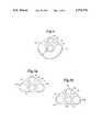
- FIG. 1ais a perspective view of the vein removal device of the present invention
- FIG. 1bis a fragmented top view of the removable proximal end of the device
- FIG. 1cis a rear view of a portion of the device.
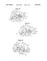
- FIGS. 2a and 2bare top views of FIG. 1a illustrating the incremental advancement of the dissecting element and the advancement of the body portion of the device, respectively.
- FIGS. 3a, 3b and 3care partially exploded views of the actuator handle, top view of the actuator lever, and front view of the actuator lever, respectively.
- FIG. 4is a cross-sectional view of a first embodiment of the multi-lumen body portion of the device taken along line 4--4 of FIG. 1.
- FIG. 5is a cross-sectional view similar to FIG. 5 of a second embodiment of the body portion of the device of FIG. 1.
- FIGS. 6a and 6bare sectional views taken along line 6--6 of FIG. 1a.
- FIGS. 7a and 7bare partial sectional views taken along line 7--7 of FIG. 6a.
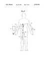
- FIG. 8is a schematic view of the vein harvesting device of the present invention being used in the removal of the saphenous vein of a patient.
- FIG. 9ais a side sectional view of a ligation-cutting tool of the present invention, with it's distal end shown enlarged in perspective
- FIG. 9bis a top plan view of the distal end of the ligation-cutting tool of FIG. 9a
- FIG. 9cis a side elevational view of the distal end of the ligation-cutting tool of FIG. 9a.
- FIG. 10is a side elevational view of a side-biting ligation-cutting tool of the present invention, with it's distal end enlarged in perspective.
- FIG. 11is a side elevational view of a suction-coagulator tool of the present invention.
- FIGS. 12 and 13are enlarged perspective illustrations showing the distal end of the vein harvesting tool in use during the harvesting of a blood vessel.
- FIGS. 14, 15 and 16are enlarged perspective illustrations showing the distal end of the vein harvesting device and the tools of FIGS. 9-11 in use during the harvesting of a blood vessel.
- FIGS. 1-8The structure of the vein harvesting device of the present invention can be understood generally with reference to FIGS. 1-8.
- the tools which are used in connection with the device during the vein harvesting procedureare shown in FIGS. 9-11 while FIGS. 12-16 illustrate the device and it's associated tools being used in a vein harvesting procedure.
- the present inventionis a device and method for harvesting a section of cylindrical and/or tubular tissue structure such as a vessel from a patient's body.
- the inventionalso has application for removing such tissue from animal bodies.
- the sectionmay be used in another part of a patient's body or for transplanting into a second patient's body.
- a section of the saphenous veinmay be removed for use in coronary bypass surgery.
- the blood vesselneeds to be removed without undue damage to the blood vessel, as well as with minimal damage and trauma to the patient.
- FIG. 1ais a perspective view of the vein harvesting device 10 in accordance with the present invention.
- Device 10includes a housing 12 through which an elongated body portion 14 is advanced during a vein harvesting procedure.
- Housing 12 and body portion 14may be constructed of a rigid material such as metal or plastic.
- a remote actuation handle 16is connected to housing 12 by a flexible biaxial cable 18.
- Actuation handle 16is used to selectively advance either body portion 14 or vein dissection element 20 in a manner which will be more fully described with respect to FIGS. 2 and 3.
- Vein dissection element retraction knob 22protrudes from housing 12 and allows vein dissection element 20 to be retracted during the procedure.
- body portion 14includes vessel lumen 24, viewing lumen 26, irrigation lumen 28 and working lumen 30.
- Each of the lumensruns longitudinally through body portion 14 from an opening at the distal end to an exit port at or near the proximal end of the body portion as seen in FIG. 1c.
- Working lumen 30has its exit port 31 at the proximal end of body portion 14.
- Irrigation lumen 28has an exit port 29 (FIG. 1a) which may be connected to a source 46 of irrigant (FIG. 8). The function of each lumen will be described in more detail hereafter.
- Body portion 14is of sufficient size and shape to accommodate the lumens.
- Lumen 24is of a size large enough to accommodate the blood vessel which is to be harvested and dissection element 20.
- a vein attachment clip 32is clipped to the vessel.
- Vein attachment clip 32is connected via cable 34 to a spring mechanism 36 which maintains a positive tension on the vessel in the direction of the proximal end of the vessel lumen during the dissection procedure. This eliminates the need to use a separate gripping forceps to hold the vessel during the procedure as in U.S. Pat. No. 5,373,840.
- Vessel lumen 24may be provided with an irrigation port 25 which may be connected to a source of irrigant (not shown) to allow irrigation of the vessel being harvested, as desired.
- Vessel lumen 24is substantially circular and has a diameter and length which may be varied depending upon the length of the vein section to be harvested and/or the size of the patient from which the vein is to be removed. Typically, the length of body portion 14 will be in the range of 30 to 60 cm and the diameter of the vessel lumen 24 will be in the range of 5-7 mm.
- Endoscope lumen 26is sized to accommodate a fiber optics viewing device 38 which includes an appropriate fiber optics illumination source.
- Device 38is positioned such that the area immediately adjacent the distal end of body portion 14 can be illuminated and viewed by the operator.
- device 38is operably connected to an external monitor 40 which includes a suitable light source by conduit 42.
- Conduit 42enters the endoscope lumen at endoscope port 44 (FIG. 1a).
- Irrigation channel 28is operable coupled to the external source of irrigant 46 via a suitable conduit 48.
- Vein dissection element 20is used to aid in separating the vessel being harvested from the surrounding tissue.
- Dissection element 20has a generally rigid cylindrical body which may be comprised of metal or rigid plastic. The diameter of the cylindrical body of dissection element 20 is sized to accommodate the vessel being harvested. The distal end of the dissection element has a rounded or beveled distal edge 50 used to separate the blood vessel from the surrounding connective tissue as the dissecting element 20 is advanced over the blood vessel.
- Dissecting element 20is provided in a plurality of sizes for different sizes of blood vessels. Typical sizes would have inside diameters of 4 mm, 5 mm, and 6 mm.
- the cylindrical shape of dissection element 20protects the dissected portion of the vessel which is located within the dissection element. This feature is especially important in those embodiments of the invention where the vessel lumen is not separate from the working lumen (i.e. FIG. 5b).
- the structuremay take the form of an elongated shaft having attached at it's proximal end an annular dissecting ring.
- This constructionwould be similar to the dissecting tool disclosed in U.S. Pat. No. 5,373,840 discussed above.
- a dissection element so constructedmay be inserted through vessel lumen 24 or, in the alternative, may be inserted through a separate working lumen. Utilizing a separate lumen allows the vessel to be completely isolated while in the vessel lumen from the shaft of the dissection element and from all tools used in the procedure.
- working lumen 30is generally arcuate in shape and positioned generally around the periphery of vessel lumen 24.
- Working lumen 30is sized to accommodate the various tools used in the vein harvesting procedure which will be discussed in more detail with respect to FIGS. 9-11.
- lumen 30will be sized such that dimension X in FIG. 4 is in the range of 5-10 mm.
- the shape of lumen 30advantageously allows the tools to be used in various locations around each side and the underside of the vein.
- the separate working lumenallows the tools used in the procedure to be completely separated from the dissected portion of the vessel in the vessel lumen thus reducing the possibility of damaging the vessel with the tools.
- FIGS. 5a and 5bare views similar to FIG. 4 of alternative configurations for body portion 14.
- the body portionis provided with multiple working lumens 30A and 30B in FIG. 5a.
- the working vessel lumensare combined into a single lumen having working sections 30C and 30D and vessel section 24A.
- Body portion 14 of FIG. 5ais similar to that of FIG. 4 in that the vessel lumen 24 is separate from the working lumen 30A and 30B.
- the embodiment of FIG. 5aallows the tools used in harvesting the vein to be inserted on either side of the vessel lumen 24.
- the size and shape of working lumens 30A and 30Bis selected to accommodate the tools used in the procedure.
- the lumens 30A and 30Bare generally circular in cross-section and have a diameter in the range of about 5-10 mm.
- the embodiment of body portion 14 of FIG. 5bhas a single combined working and vessel lumen with working sections 30C and 30D and vessel section 24A.
- Section 30C and 30Dare of a size and shape to accommodate the tools used in the procedure.
- the vesselis protected from the tools by dissection element 20. Additionally, the vessel may be protected by shaping (i.e. as by narrowing) the junctions between the working sections and the vessel section such that the tools may not substantially enter the vessel section. Other means of protecting the vessel may be employed such as by intermittently partitioning the working sections from the vessel section.
- Vein attachment clip 32is used to hold and retain the vessel being harvested during the procedure.
- Vein attachment clip 32includes first and second opposed jaws 52 and 54, respectively. The jaws are tensioned towards the closed position similar to an alligator clip which allows the jaws to obtain a firm grip on the vessel.
- a latching mechanismmay be provided which locks the jaws in a set position.
- Spring mechanism 36maintains a positive tension on vein attachment clip 32 through cable 34 towards the proximal end of lumen 24 thus maintaining tension on the vessel during the course of the dissection procedure.
- Spring mechanism 36is located within a removable container 37 which is connected to the proximal end of vessel lumen 24 by a bayonet lock mechanism 39. Container 37 may be removed to allow access to the dissected vein by pushing housing 37 towards the distal end of body portion 14 while twisting the housing 90° clockwise.
- remote actuation handle 16is a scissors-type actuator and includes a lever 56.
- Lever 56is positioned so that it may be moved to the right or left by the thumb of the operator.
- Lever 56is used to engage one of two cables, 58 and 60, one of which is connected through biaxial cable 18 to a body portion advancement mechanism 62 and the other of which is connected to a dissection element advancement mechanism 64 (FIGS. 6a and 6b).
- the operatormay choose to advance body portion 14 by moving lever 56 to the left.
- Lever 56includes notches 66A and 66B which accommodate cables 58 and 60, respectively. When lever 56 is moved to the left as shown in FIG. 3c cable 58 fits within notch 66A.
- a stop 68is provided at the end of cable 58 which is larger than notch 66A so that when the operator squeezes the handles of the scissors-type actuating handle together cable 58 is retracted from biaxial cable 18.
- a stopped 70is provided on cable 60 so that when lever 56 is moved to the right cable 60 may be retracted by squeezing scissors-type actuation handle 16.
- FIGS. 6a, 6b, 7a and 7bare cross-sectional views of the interior of the housing 12.
- Body portion advancement mechanism 62includes ratchet wheel 72 fixedly connected to a spoked wheel 74 which rotates about an axle 73.
- Axle 73is fixedly mounted to housing 12 in a manner not shown in FIGS. 6a and 6b in order to simplify the Figures for purposes of clarity.
- Wheel 74has spaced along its circumference a plurality of generally circular pegs 76.
- dissection element advancement mechanism 64includes a toothed ratchet wheel 78 fixedly connected to a spoked wheel 80 having a plurality of pegs 82 spaced along its circumference.
- retraction by the operator of cable 58actuates body portion advancement mechanism 62 causing body portion 14 to advance in the distal direction through housing 12 while retraction of cable 60 causes dissection element advancement mechanism 64 to advance dissection element 20 through lumen 24.
- FIGS. 7a and 7bare fragmentary cross-sectional views of dissection element advancement mechanism 64 showing cable 60 in the extended position (FIG. 7a) and in the retracted position (FIG. 7b).
- Spokes 82 along the circumference of spoked wheel 80extend through a slot 86 in body portion 14 (FIGS. 4 and 5) and align with mating openings 84 on the surface of dissection element 20. Therefore, rotation of spoked wheel 80 causes either advancement or retraction of dissection element 20 depending upon direction of rotation. Rotation of spoked wheel 80 may be imparted by retraction of cable 60 by the operator manipulating remote actuator 16 in the appropriate manner.
- Cable 60extends through biaxial cable 18 into housing 12 through a fixed member 86 which is either a portion of the housing or fixed thereto.
- Fixed member 86has a plug 88 which acts as a stop for a spring 90.
- Cable 60extends through plug 88 and spring 90 and is fixedly connected to a movable cylinder 92 ratchet arm 94 is movably connected to one side of cylinder 92.
- a Ratchet arm 94pivots about a point 96 and is positioned such that its narrow distal tip 97 mates with teeth 98 on toothed ratchet wheel 78.
- each squeeze of the actuation handlewill cause the dissection element to advance 5 mm.
- the remote actuator handle 16is released cylinder 92 returns to it's original position (shown in dotted line in FIG. 7b) due to the force exerted by spring 90.
- Pivot arm 96is constructed so that it is fixed with respect to rotation towards the left side of FIG. 7b but will rotate towards the right side of FIG. 7b.
- pivot arm 96will ride over the surface of the next tooth 98B. It thus returns to the position of FIG. 7a and is ready for the next incremental advancement of dissection element 20.
- Body portion 14is advanced in a manner similar to that of dissection element 20. The only difference being that pegs 76 of spoked wheel 74 are aligned to engage with mating openings 99 in body portion 14. Lever 56 is moved to the right so that activation of scissors-type handle 16 will cause incremental advancement of body portion 14.
- retraction knob 22is provided to enable dissection element 20 to be retracted by the operator during the vein harvesting procedure.
- vein dissection element 20is advanced in 5 mm increments to a length of about 5 cm past the distal end of the body portion as shown in FIG. 2a.
- body portion 14is advanced as shown in FIG. 2b.
- a suitable clutch 87is provided to prevent dissection element 20 from being advanced when a side branch is encountered.
- Clutch 87may be of conventional construction and function to cause toothed ratchet wheel 78 to slip with respect to spoked wheel 80 if the resistance in the advancement of dissection element 20 exceeds a predetermined level which may cause damage to the side branch.
- dissection element 20may be retracted.
- Retraction of dissection element 20is accomplished as shown in FIG. 6b by depressing retraction knob 22 in the direction of housing 12.
- Knob 22is connected to shaft 81 which extends through a stationary guide 83.
- Knob 22 and shaft 81are biased in the position shown in FIG. 6a by a spring 85.
- knob 22When knob 22 is depressed as in the direction of arrow 508 in FIG. 6b shaft 81 causes toothed ratchet wheel 78 to become disengaged from pivot arm 96.
- rotation of knob 22 in a counterclockwise direction as shown by arrow 510causes spoked wheel 80 to rotate in a direction opposite to that shown by arrow 505 in FIG. 7b.
- This correspondinglycauses dissection element 20 to move in a direction opposite arrow 506 thus resulting in retraction of dissection element 20.
- FIG. 8when device 10 is used to harvest a blood vessel such as a saphenous vein 100, the device is used in conjunction with several tools. These tools are inserted into the working lumen 30 (FIG. 4), 30A, 30B (FIG. 5a), or sections 30C, 30D (FIG. 5b) of body portion 14 at an entrance port (i.e. port 31, FIG. 1c) located at the proximal end of the lumen. This allows the tools to be isolated from the vein during the dissection procedure to further protect the vein from any damage from tools being inserted, retracted or manipulated during the course of the procedure.
- a ligation-cutting tool 200(FIG. 9) is used when severing side branches 102 from the blood vessel 100.
- a side-biting ligation-cutting tool 250(FIG. 10) is used to transect the blood vessel 100 when the dissection is completed.
- a suction-coagulator tool 300(FIG. 11) is used to control bleeding during the procedure.
- the ligation-cutting tool 200(FIG. 9a, 9b and 9c) is used to sever and seal side branches on the vessel being harvested.
- the ligation-cutting tool 200has an elongated shaft 201, with a ligation clip applicator 202 and a cutting mechanism 204 at the distal end of the shaft 201.
- the ligation clip applicator 202includes a first yoke 208 and a second opposed yoke 210. Each yoke 208 and 210 is in turn divided into two sections. Each yoke 208 and 210 is forked at it's distal end, forming two opposed prongs 212A and 212B on the yokes 208 and 210, respectively.
- the prongs 212A and 212B on the yokes 208 and 210are parallel to each other and generally aligned with the longitudinal axis of the ligation-cutting tool 200.
- the yokes 208 and 210 and the prongs 212A and 212B thereonoppose each other and serve to apply ligation clips 216 (see FIGS. 9b and 9c) to a side branch 102 being severed.
- the opposing prongs 212A and 212B of each yoke 208 and 210contain two grooves 214 respectively, to securely hold a ligation clip 216 therein.
- the generally U-shaped ligation clips 216aid the operator in properly aligning the ligation-cutting tool 200 and the side branch 102 to be ligated by providing an abutment for the side branch 102 when side branch 102 is positioned between yokes 208 and 210.
- the yokes 208 and 210are biased towards each other in a conventional manner, the ligation clips 216 are deformed to clamp onto the side branch 102 there between and the blood flow through the side branch 102 is halted at two slightly spaced apart points (e.g., two clips are applied approximately 0.25 inches apart).
- the ligation clip applicator 202is activated and the yokes 208 and 210 clamp the ligation clips 216 onto the side branch 102, the side branch 102 is held securely for cutting the side branch 102.
- the cutting mechanism 204 on the ligation-cutting tool 200includes a cutting blade 230 aligned between the prongs 212A and 212B and proximal to the ligation clips 216.
- the cutting blade 230is normally retracted (as seen in FIGS. 9a, 9b and 9c) to allow the side branch 102 to be positioned properly between the yokes 208 and 210.
- a cutting edge 232 of the blade 230faces the distal end of the ligation-cutting tool 200 and the cutting motion of the blade 230 is in a distal direction (e.g., towards the side branch 102).
- the blade 230is wide enough to completely sever the side branch 102 between the two yokes 208 and 210.
- the cutting mechanism 204is activated by the operator (as described below) after the side branch 102 has been ligated (i.e., the side branch 102 has been clipped shut and blood flow halted) and while the side branch is still held securely in the yokes 208 and 210. After the blade 230 has severed the side branch 102, the blade 230 returns into it's original retracted position.
- the ligation clip applicator 202 and the cutting mechanism 204are both actuated by mechanisms by the proximal end of the shaft 201 of the ligation-cutting tool 200.
- the ligation clip applicator 202is preferably actuated by a scissors-type handle 220.
- a scissors-type handle 220By squeezing the scissors-type handle 220, the operator causes each set of prongs 212A and 212B on the yokes 208 and 210 to be moved together, thereby compressing their respective ligation clip 216 about the side branch 102 of the blood vessel 100 as described above.
- the scissors-type handle 220includes a latching mechanism 222 which serves to secure the handle 220 and thus the ligation clip applicator 202 in a closed or clamped position.
- the cutting mechanism 204is actuated, preferably by a plunger 204 located at the proximal end of the ligation-cutting tool 200.
- the plunger 224is operably connected to the cutting blade 230 and biased proximally to urge the blade 230 into it's normally retracted position.
- the operatorBy moving the plunger 224 distally, the operator causes the cutting blade 230 to likewise move distally and cut the side branch 102 of the blood vessel 100 which is retained between the yokes 208 and 210.
- the plunger 224retracts to it's original position.
- Manipulation of the handle 220then separates the prongs 212A and 212B, leaving the clip in place on the severed portions of the side branch 102 and the ligation-cutting tool 200 is removed or relocated for reuse (the clips may be fed into place in the grooves of the prongs from a suitable clip magazine not shown) to enable multiple ligations without removing the tool from the body.
- the shaft 201 of the ligating-cutting tool 200is a slender member that is longer than the working lumen (30 in FIG. 4, 30A, 30B in FIG. 5a, 30C, 30D in FIG. 5b).
- a housing 209covers those mechanisms on the shaft 201 that transmit the manipulations of the handle 220 and the plunger 224 at the proximal end of the ligation-cutting tool 200 to the clipping and cutting motions, respectively, at the distal end of ligation-cutting tool 200.
- the side biting-ligation-cutting tool 250(FIG. 10) is used to sever and seal the distal end of the vessel being harvested.
- the side-biting ligation-cutting tool 250is identical in operation to the ligation tool 200, except that the operative components at the distal end of the tool 250 are oriented generally normally to the axis of the tool 250.
- the side-biting ligation-cutting toolhas an elongated shaft 251, with a ligation clip applicator 252 and a cutting mechanism 254 at the distal end of shaft 251.
- the ligation clip applicator 252includes a first yoke 258 and a second, opposed yoke, 260.
- Each yokein turn is forked at it's distal end, forming two opposed prongs 262A and 262B, respectively.
- the prongsare aligned generally parallel and each has two grooves 264 to retain ligation clips between each opposed pair of prongs 262A and 262B.
- the structure and operation of the ligation clip applicator 252is similar to that illustrated in FIGS. 9b and 9c for the ligation-cutting tool 200.
- the yokes 258 and 260 and the prongs 262A and 262B thereonoppose each other and serve to apply ligation clips not shown in FIG. 10 to the distal end of the segment of the blood vessel being severed.
- the generally U-shaped ligation clipsaid in positioning and properly aligning the side-biting ligation-cutting tool 250 and the blood vessel to be transected by providing an abutment for the blood vessel when the blood vessel is positioned in the yokes 258 and 260.
- the ligation clipsare clamped onto the blood vessel there between and the blood flow through the blood vessel is halted at two slightly spaced-apart points (e.g., two clips are applied approximately 0.25 inches apart).
- the ligation clip applicator 252is activated and the yokes 258 and 260 clamp the ligation clips onto the blood vessel, the blood vessel is also held securely for cutting the blood vessel.
- the cutting mechanism 254 on the side-biting ligation-cutting tool 250includes a cutting blade 280 aligned between the prongs 262A and 262B. Again, the structure of the cutting mechanism for the tool 250 is quite similar to that illustrated in FIGS. 9b and 9c for the ligation-cutting tool 200.
- the blade 280is positioned such that a cutting edge 282 of the blade 280 does not interfere with the alignment of the blood vessel between the yokes 258 and 260.
- the cutting blade 280is normally retracted (as seen in FIG. 10) to allow the blood vessel to be positioned properly between yoke 258 and 260.
- the cutting edge 282 of the blade 280faces in a transverse direction from the shaft 251 of the side-biting ligation-cutting tool 250, and the cutting motion of the blade 280 is in a transverse direction (e.g., toward the blood vessel).
- the blade 280is wide enough to completely sever the blood vessel between the two yokes 258 and 260.
- the cutting mechanism 254is activated after the blood vessel has been ligated (the blood vessel has been clipped shut and the blood flow halted) and while the blood vessel is still held securely in the yokes 258 and 260. After the blade 280 has severed the blood vessel, the blade 280 returns to its original retracted position.
- the primary difference between the tool 200 and tool 250is that the distal operative portion of the tool 250 is oriented at an angle generally 90 degrees opposed to the axis of the shaft 251 of the tool 250.
- the yokes 258 and 260are thus oriented to straddle a blood vessel extending generally parallel to the shaft 251 to apply ligation clips thereto. After clips are applied, the yokes continue to hold the blood vessel to permit severing of the vessel using the blade 280.
- the revision in orientation of the distal portion of the ligation-cutting tool 250it operates in the same manner as the ligation-cutting tool 200.
- the ligation clip applicator 252 and the cutting mechanism 254are both actuated by mechanisms at the proximal end of the shaft 251 of the ligation-cutting tool 250.
- the ligation clip applicator 252is preferably actuated by a scissors-type handle 270. Squeezing of the scissors-type handle 270 causes each pair of prongs 262A and 262B on the yokes 258 and 260 to move together, thereby compressing their respective ligation clips about the blood vessel.
- the scissors-type handle 270includes a latching mechanism 272 which serves to secure the handle 270 and thus the ligation clip applicator 252 in a closed or clamped position.
- the ligation cutting mechanism 254is actuated, preferably by a plunger 274 located at the proximal end of the ligation-cutting tool 250.
- the plunger 274is operably connected to the cutting blade 280, and biased proximally to urge the blade 280 into its normally retracted position.
- the operatorBy moving the plunger 274 distally, the operator causes the cutting blade 280 to likewise move distally and cut the blood vessel which is retained between the yokes 258 and 260.
- the plunger 274retracts to its original position. Manipulation of the handle 270 then separates the prongs 262A and 262B, leaving the clips in place on the severed portion of the blood vessel, and the ligation-cutting tool 250 is removed.
- the shaft 251 of the side-biting ligation-cutting tool 250is a slender member that is longer than the working lumen of device 10.
- a housing 259covers those mechanisms on the shaft 251 that transmit the manipulations of the handle 270 and the plunger 274 at the proximal end of the side-biting ligation-cutting tool 250 to the clipping and cutting motion, respectively, at the distal end of the side-biting ligation-cutting tool 250.
- the suction-coagulator tool 300(FIG. 11) is used to remove body fluid (e.g., blood) and reduce bleeding during the vessel harvesting procedure, and is of the type generally known in the art for this procedure.
- the suction-coagulator tool 300has an elongated shaft 301 and includes a handle 310 attached to the proximal end of the shaft 301.
- a suction tube 302is attached to the proximal end of shaft 301 and extends to the distal end of shaft 301. At the distal end of shaft 301 the suction tube 302 is opened for suctioning body fluids.
- a power cable 304is also attached to the proximal end of shaft 301 for supplying power for tissue coagulation.
- the suction-coagulator tool 300controls bleeding in two ways.
- the suction tube 302may be used alone to suction any body fluids from the dissection area, or the coagulator may be used to cauterize the bleeding tissue.
- the vein harvesting device 10 and accompanying tools 200, 250 and 300are used in combination for harvesting a vessel.
- the physicianmakes a small incision 350 (e.g. 3 cm long) over the proximal aspect of the blood vessel to be harvested (see FIGS. 8 and 12).
- the blood vessel 100is exposed and dissected for a short length under direct vision.
- the blood vessel 100is then severed to expose a free end 352 and a free end 353 (which may be clipped as shown in FIG. 12).
- the incision 350will be made at the groin over the saphenous vein and the vein will be dissected free from the junction common femoral vein. As shown in FIGS.
- the vein attachment clip 32is inserted through the dissecting element 20, both of which are accommodated within vessel lumen 24 of vein harvesting device 10 such that the distal ends of dissecting element 20 and vein attachment clip 32 extend beyond the distal end of lumen 24.
- the free end 352 of blood vessel 100is attached to vein attachment clip 32 such that it is held under tension in the manner previously described.
- the vein harvesting device 10is secured in a fixed position to the patient's body such as with tape.
- the dissecting element 20is then advanced distally over the distal end of the attachment clip 32 and over the blood vessel 100. As the dissecting element 20 is manipulated by the operator from remote actuation handle 16, the blood vessel 100 is dissected away from surrounding connective tissue.
- the dissection processproceeds distally along the blood vessel 100.
- the body portion 14is advanced along with the dissecting element 20 into the incision 350.
- the operatorhas been viewing the procedure under direct vision.
- the operatorswitches to viewing the dissection process (occurring at the area immediately adjacent the distal end of the lumen 24) through the fiber optic viewing device 38 located at the distal end body portion 14.
- the vein devicecould be provided by a separate scope.
- device 38provides adequate lighting for the operator to view the dissection and tool operations occurring within the patient via the monitor. Irrigant is introduced as necessary through irrigation channel 28 to keep blood or other body tissue from obscuring vision adjacent the distal end of the body portion 14.
- a side branch 102 of the blood vessel 100may be encountered before the desired length of blood vessel 100 has been dissected.
- clutch 87(FIGS. 6a and 6b) prevents dissection element from being advanced when a side branch is encountered. This is particularly important when the side branch lies under vessel 100 where it may not be visible to the operator.
- the ligation-cutting tool 200is employed to sever the side branch 102 from the vessel 100 being harvested as shown generally in FIGS. 14 and 15.
- the operatorstops advancing the dissecting element 20 and the body portion 14 and, if necessary, withdraws the dissecting element 20 proximally from the side branch 102 to provide room for the operation of the ligation-cutting tool 200.
- the ligation-cutting tool 200is inserted into the proximal end of working lumen 30 and advanced distally through lumen 30 and into the area distal of body portion 14.
- the operatorpositions the ligation-cutting tool over the side branch 102 such that the side branch 102 is sitting in the yokes 208 and 210 (see FIG. 14).
- the operatormanipulates the handle 220 of the ligation-cutting tool 200 to actuate the ligation clip applicator 202.
- the prongs 212A and 212B on each of the yokes 208 and 210move toward each other, the ligation clips 216 are clamped about the side branch 102 thereby stopping blood flow to the side branch 102.
- the operatorpushes the plunger 224 to activate the cutting mechanism 204.
- the cutting blade 230thus moves distally into and through the side branch 102, thereby severing the side branch 102 from the blood vessel 100 between the ligation clips 216.
- the plunger 224is released by the operator, the cutting blade 230 returns to it's original retracted position.
- the handle 220is then manipulated to separate the prongs 212A and 212B, and the ligation-cutting tool 200 is withdrawn proximally through the working lumen 30 of body portion 14.
- the ligation-cutting tool 200may then be prepared to be used again later in the procedure (i.e., reloaded with additional clips 216), if required.
- the dissecting element 20 and body portion 14are again advanced distally along the blood vessel 100 by the operator using the remote actuation handle 16 (as previously described) until another side branch is reached.
- the dissecting element 20is large enough to pass over the clip and severed stumps of any side branches 102 which extend from the blood vessel 100.
- the ligation-cutting tool 200is then used as previously described to sever additional side branches from the blood vessel 100. The procedure is repeated until the desired length of blood vessel 100 has been dissected free from all the surrounding tissue and side branches.
- the suction-coagulator tool 300is used as required to control bleeding, again under the constant vigilance of the operator.
- the blood vessel 100has been held in tension by vein attachment clip 32 which is biased in the proximal direction by spring mechanism 36. It is, thus, unnecessary for the operator to use a separate gripping tool for the purpose of holding the vessel under tension. This frees the operator to concentrate on the other aspects of the dissection procedure.
- the body portion 14is advanced distally into the patient's body and the blood vessel 100 is moved into vessel lumen 24 of body portion 14.
- the dissecting element 20is moved proximally away from the distal end of the dissected vessel segment, and the side-biting ligation-cutting tool 250 is inserted into the proximal end of the working lumen 30 and advanced distally through lumen 30 into the area adjacent the distal end of body portion 14 and the distal end of the dissected blood vessel 100.
- the side-biting ligation-cutting tool 250is positioned such that the blood vessel 100 is between the first yoke 258 and the second yoke 260 of the ligation clip applicator 252, as seen in FIG. 16.
- the operatormanipulates the handle 270 to actuate the ligation clip applicator 252.
- the yokes 258 and 260move toward each other, the yokes 258 and 260 act to pinch the ligation clips 266 over the distal end of the dissected blood vessel 100 (thus stopping blood flow through the blood vessel 100).
- the operatorpushes the plunger 274 to activate the cutting mechanism 254.
- the cutting blade 280advances between the ligation clips 266 and through the blood vessel 100 to sever the blood vessel 100 into a freed section 360 having free end 352 (FIG.
- the handle 270is manipulated to separate the prongs 262A and 262B, and the side-biting ligation-cutting tool 250 is withdrawn proximally through the lumen 30 of body portion 14.
- the tool 250may apply ligation clips on sections 360 and 362, or just one clip on the remaining section 362 of the blood vessel 100.
- the freed section 360 of the blood vessel 100is now free of all connections to the patient's body and is substantially within vessel lumen 24 of body portion 14.
- the desired section of dissected vesselmay be removed by releasing the bayonet lock 39 at the proximal end of vessel lumen 24 and then by pulling the vein through the proximal end of lumen 24. Once removed the freed section 360 of blood vessel 100 may then be prepared for it's intended use or be discarded.
Landscapes
- Health & Medical Sciences (AREA)
- Surgery (AREA)
- Life Sciences & Earth Sciences (AREA)
- Medical Informatics (AREA)
- Animal Behavior & Ethology (AREA)
- Engineering & Computer Science (AREA)
- Biomedical Technology (AREA)
- Heart & Thoracic Surgery (AREA)
- Rheumatology (AREA)
- Molecular Biology (AREA)
- Nuclear Medicine, Radiotherapy & Molecular Imaging (AREA)
- General Health & Medical Sciences (AREA)
- Public Health (AREA)
- Veterinary Medicine (AREA)
- Surgical Instruments (AREA)
- Prostheses (AREA)
- External Artificial Organs (AREA)
Abstract
Description
Claims (96)
Priority Applications (9)
| Application Number | Priority Date | Filing Date | Title |
|---|---|---|---|
| US08/570,229US5772576A (en) | 1995-12-11 | 1995-12-11 | Apparatus and method for vein removal |
| PCT/US1996/020775WO1997021398A1 (en) | 1995-12-11 | 1996-12-11 | Apparatus and method for vein removal |
| EP96945099AEP0840576B1 (en) | 1995-12-11 | 1996-12-11 | Apparatus for vein removal |
| CA002212650ACA2212650C (en) | 1995-12-11 | 1996-12-11 | Apparatus and method for vein removal |
| DE69632686TDE69632686D1 (en) | 1995-12-11 | 1996-12-11 | VENIC EXTRACTION DEVICE |
| AU13548/97AAU1354897A (en) | 1995-12-11 | 1996-12-11 | Apparatus and method for vein removal |
| US09/107,158US6071232A (en) | 1995-12-11 | 1998-06-29 | Apparatus for vein removal |
| US09/586,825US6428468B1 (en) | 1995-12-11 | 2000-06-05 | Apparatus and method for vein removal |
| US10/165,396US7066875B2 (en) | 1995-12-11 | 2002-06-07 | Apparatus and method for vein removal |
Applications Claiming Priority (1)
| Application Number | Priority Date | Filing Date | Title |
|---|---|---|---|
| US08/570,229US5772576A (en) | 1995-12-11 | 1995-12-11 | Apparatus and method for vein removal |
Related Child Applications (1)
| Application Number | Title | Priority Date | Filing Date |
|---|---|---|---|
| US09/107,158ContinuationUS6071232A (en) | 1995-12-11 | 1998-06-29 | Apparatus for vein removal |
Publications (1)
| Publication Number | Publication Date |
|---|---|
| US5772576Atrue US5772576A (en) | 1998-06-30 |
Family
ID=24278785
Family Applications (4)
| Application Number | Title | Priority Date | Filing Date |
|---|---|---|---|
| US08/570,229Expired - LifetimeUS5772576A (en) | 1995-12-11 | 1995-12-11 | Apparatus and method for vein removal |
| US09/107,158Expired - Fee RelatedUS6071232A (en) | 1995-12-11 | 1998-06-29 | Apparatus for vein removal |
| US09/586,825Expired - Fee RelatedUS6428468B1 (en) | 1995-12-11 | 2000-06-05 | Apparatus and method for vein removal |
| US10/165,396Expired - Fee RelatedUS7066875B2 (en) | 1995-12-11 | 2002-06-07 | Apparatus and method for vein removal |
Family Applications After (3)
| Application Number | Title | Priority Date | Filing Date |
|---|---|---|---|
| US09/107,158Expired - Fee RelatedUS6071232A (en) | 1995-12-11 | 1998-06-29 | Apparatus for vein removal |
| US09/586,825Expired - Fee RelatedUS6428468B1 (en) | 1995-12-11 | 2000-06-05 | Apparatus and method for vein removal |
| US10/165,396Expired - Fee RelatedUS7066875B2 (en) | 1995-12-11 | 2002-06-07 | Apparatus and method for vein removal |
Country Status (6)
| Country | Link |
|---|---|
| US (4) | US5772576A (en) |
| EP (1) | EP0840576B1 (en) |
| AU (1) | AU1354897A (en) |
| CA (1) | CA2212650C (en) |
| DE (1) | DE69632686D1 (en) |
| WO (1) | WO1997021398A1 (en) |
Cited By (46)
| Publication number | Priority date | Publication date | Assignee | Title |
|---|---|---|---|---|
| US6358244B1 (en) | 1996-07-12 | 2002-03-19 | Endo Surgical Devices, Inc. | Endarterectomy surgical instrument and procedure |
| WO2002039882A2 (en) | 2000-11-17 | 2002-05-23 | Embro Vascular | Vein harvesting system and method |
| US6428468B1 (en)* | 1995-12-11 | 2002-08-06 | Cardiothoracic Systems, Inc. | Apparatus and method for vein removal |
| US6443970B1 (en) | 2001-01-24 | 2002-09-03 | Ethicon, Inc. | Surgical instrument with a dissecting tip |
| US6464702B2 (en) | 2001-01-24 | 2002-10-15 | Ethicon, Inc. | Electrosurgical instrument with closing tube for conducting RF energy and moving jaws |
| US20020198551A1 (en)* | 1999-11-16 | 2002-12-26 | Grant Kevin Lee | Endoscopic tissue separator surgical device |
| US6511494B1 (en) | 2000-11-17 | 2003-01-28 | Embro Corporation | Vein harvesting system and method |
| US6554829B2 (en) | 2001-01-24 | 2003-04-29 | Ethicon, Inc. | Electrosurgical instrument with minimally invasive jaws |
| US6620161B2 (en) | 2001-01-24 | 2003-09-16 | Ethicon, Inc. | Electrosurgical instrument with an operational sequencing element |
| US6652521B2 (en) | 2001-01-24 | 2003-11-25 | Ethicon, Inc. | Surgical instrument with a bi-directional cutting element |
| US6695840B2 (en) | 2001-01-24 | 2004-02-24 | Ethicon, Inc. | Electrosurgical instrument with a longitudinal element for conducting RF energy and moving a cutting element |
| US20040204725A1 (en)* | 2001-06-26 | 2004-10-14 | Bayer Hanspeter Robert | Conduit harvesting instrument and method |
| US20040226972A1 (en)* | 2003-02-18 | 2004-11-18 | Tactical Design Labs | Ergonomic duty belt |
| US20040236231A1 (en)* | 2003-05-23 | 2004-11-25 | Embro Corporation | Light catheter for illuminating tissue structures |
| US20050064616A1 (en)* | 2003-09-23 | 2005-03-24 | Been-Yih Jin | Semiconductor channel on insulator structure |
| US20050096646A1 (en)* | 2003-10-31 | 2005-05-05 | Parris Wellman | Surgical system for retracting and severing tissue |
| US20050096671A1 (en)* | 2003-10-31 | 2005-05-05 | Parris Wellman | Control mechanism for a surgical instrument |
| US20050096670A1 (en)* | 2003-10-31 | 2005-05-05 | Parris Wellman | Surgical end effector |
| US20050096645A1 (en)* | 2003-10-31 | 2005-05-05 | Parris Wellman | Multitool surgical device |
| US20050273125A1 (en)* | 2004-05-13 | 2005-12-08 | Opie John C | Percutaneous vein harvester with shielded blade |
| US20060030756A1 (en)* | 2004-06-25 | 2006-02-09 | Usher Raymond W | Vein harvesting system including dilator shaft and removable retractor housing |
| US20060036274A1 (en)* | 2004-06-25 | 2006-02-16 | Usher Raymond W | One-piece vessel harvester |
| US20060173474A1 (en)* | 2003-10-31 | 2006-08-03 | Parris Wellman | Surgical device having a track to guide an actuator |
| US20060276815A1 (en)* | 2005-06-01 | 2006-12-07 | Converge Medical, Inc. | Devices and methods for vessel harvesting |
| US20070005084A1 (en)* | 2004-06-16 | 2007-01-04 | Clague Cynthia T | Minimally invasive coring vein harvester |
| US7314479B2 (en) | 2003-10-31 | 2008-01-01 | Parris Wellman | Space-creating retractor with vessel manipulator |
| US20080027272A1 (en)* | 2006-07-26 | 2008-01-31 | Terumo Cardiovascular Systems Corporation | Device for processing blood vessel harvested for bypass graft surgery |
| US20080161843A1 (en)* | 2006-10-16 | 2008-07-03 | Clague Cynthia T | Vessel support device and method of vessel harvesting |
| US20090112053A1 (en)* | 2006-07-26 | 2009-04-30 | Terumo Cardiovascular Systems Corporation | Blood Vessel Preparation and Preservation Kit |
| US7867163B2 (en) | 1998-06-22 | 2011-01-11 | Maquet Cardiovascular Llc | Instrument and method for remotely manipulating a tissue structure |
| US7938842B1 (en) | 1998-08-12 | 2011-05-10 | Maquet Cardiovascular Llc | Tissue dissector apparatus |
| US7972265B1 (en) | 1998-06-22 | 2011-07-05 | Maquet Cardiovascular, Llc | Device and method for remote vessel ligation |
| US20110172688A1 (en)* | 2010-01-11 | 2011-07-14 | Tyco Healthcare Group Lp | Conduit Harvesting Instrument and Method |
| US7981133B2 (en) | 1995-07-13 | 2011-07-19 | Maquet Cardiovascular, Llc | Tissue dissection method |
| US8241210B2 (en) | 1998-06-22 | 2012-08-14 | Maquet Cardiovascular Llc | Vessel retractor |
| US8613752B2 (en) | 2011-04-21 | 2013-12-24 | Cook Medical Technologies Llc | Surgical instrument for removing body tissue or vessels |
| US9498246B2 (en) | 2013-03-14 | 2016-11-22 | Saphena Medical, Inc. | Unitary endoscopic vessel harvesting devices |
| US9814481B2 (en) | 2013-03-14 | 2017-11-14 | Saphena Medical, Inc. | Unitary endoscopic vessel harvesting devices |
| US9943328B2 (en) | 2015-04-28 | 2018-04-17 | Saphena Medical, Inc. | Unitary endoscopic vessel harvesting devices with an elastic force |
| US10064611B2 (en) | 2015-07-22 | 2018-09-04 | Covidien Lp | Methods and devices for vein harvesting |
| US10299770B2 (en) | 2006-06-01 | 2019-05-28 | Maquet Cardiovascular Llc | Endoscopic vessel harvesting system components |
| US10363056B2 (en) | 2015-06-17 | 2019-07-30 | Saphena Medical, Inc. | Unitary endoscopic vessel harvesting devices |
| US10575835B2 (en) | 2014-10-14 | 2020-03-03 | Covidien Lp | Methods and devices for vein harvesting |
| US10646210B2 (en) | 2014-10-14 | 2020-05-12 | Covidien Lp | Methods and devices for vein harvesting |
| US11547466B2 (en) | 2018-06-20 | 2023-01-10 | Covidien Lp | Visualization devices and methods for use in surgical procedures |
| US12357285B2 (en) | 2019-04-05 | 2025-07-15 | Saphena Medical, Inc. | Unitary device for vessel harvesting and method of using same |
Families Citing this family (24)
| Publication number | Priority date | Publication date | Assignee | Title |
|---|---|---|---|---|
| US5899912A (en)* | 1997-12-17 | 1999-05-04 | Eaves, Iii; Felmont F. | Apparatus and method for endoscopic harvesting of elongate tissue structure |
| US6129661A (en)* | 1998-04-09 | 2000-10-10 | Smith & Nephew, Inc. | Endoscopic instrumentation with working channel |
| AU763132B2 (en)* | 1999-02-04 | 2003-07-17 | Antonio Carlos Netto Da Silva Branco | Kit for endovascular venous surgery |
| US7744613B2 (en) | 1999-06-25 | 2010-06-29 | Usgi Medical, Inc. | Apparatus and methods for forming and securing gastrointestinal tissue folds |
| US7637905B2 (en) | 2003-01-15 | 2009-12-29 | Usgi Medical, Inc. | Endoluminal tool deployment system |
| US6911032B2 (en) | 1999-11-18 | 2005-06-28 | Scimed Life Systems, Inc. | Apparatus and method for compressing body tissue |
| US6428548B1 (en)* | 1999-11-18 | 2002-08-06 | Russell F. Durgin | Apparatus and method for compressing body tissue |
| JP4617059B2 (en)* | 2001-04-20 | 2011-01-19 | パワー メディカル インターベンションズ, エルエルシー | Imaging device |
| WO2003013365A1 (en)* | 2001-08-10 | 2003-02-20 | General Surgical Innovations Inc. | Devices and methods for use in blood vessel harvesting |
| US6572615B2 (en)* | 2001-09-28 | 2003-06-03 | Ethicon, Inc. | Surgical device for applying radio frequency energy to a portion of a captured vessel |
| US6592604B2 (en) | 2001-09-28 | 2003-07-15 | Ethicon, Inc. | Vessel harvesting retractor with dissection element |
| US6656176B2 (en)* | 2001-09-28 | 2003-12-02 | Ethicon, Inc. | Vessel harvesting retractor with integral electrosurgical clamping elements |
| US6592582B2 (en) | 2001-09-28 | 2003-07-15 | Ethicon, Inc. | Vessel harvesting retractor with electrosurgical plunger |
| US7041113B2 (en)* | 2002-05-07 | 2006-05-09 | Terumo Corporation | Minimal invasive endoscopic methods and apparatus for harvesting blood vessels |
| US20040249367A1 (en)* | 2003-01-15 | 2004-12-09 | Usgi Medical Corp. | Endoluminal tool deployment system |
| EP1987788B1 (en)* | 2006-02-21 | 2016-07-20 | Olympus Corporation | Endoscope system and medical instrument |
| US8551076B2 (en)* | 2006-06-13 | 2013-10-08 | Intuitive Surgical Operations, Inc. | Retrograde instrument |
| KR101477133B1 (en)* | 2006-06-13 | 2014-12-29 | 인튜어티브 서지컬 인코포레이티드 | Minimally invasive surgical system |
| BRPI0913380A2 (en) | 2008-06-04 | 2015-11-24 | Neovista Inc | portable radiation release system for advancing a radiation source wire |
| US9498278B2 (en) | 2010-09-08 | 2016-11-22 | Covidien Lp | Asymmetrical electrodes for bipolar vessel sealing |
| WO2013096763A2 (en) | 2011-12-23 | 2013-06-27 | Pavilion Medical Innovations, Llc | Unitary endoscopic vessel harvesting devices |
| US9265514B2 (en) | 2012-04-17 | 2016-02-23 | Miteas Ltd. | Manipulator for grasping tissue |
| DE102014118003A1 (en)* | 2014-12-05 | 2016-06-23 | Karl Storz Gmbh & Co. Kg | Endoscopic instrument and endoscopic instrument system |
| US10052169B2 (en) | 2016-11-03 | 2018-08-21 | Meshil A. M. O. H. Al-Jarba | Shield for electrosurgical suction coagulator and kit including the same |
Citations (48)
| Publication number | Priority date | Publication date | Assignee | Title |
|---|---|---|---|---|
| US1867624A (en)* | 1930-04-01 | 1932-07-19 | Memorial Hospital For The Trea | Device for obtaining biopsy specimens |
| US2001169A (en)* | 1934-11-01 | 1935-05-14 | Oscar R Wallace | Building structure |
| US2011169A (en)* | 1932-04-13 | 1935-08-13 | Wappler Frederick Charles | Forcipated surgical electrode |
| US2028635A (en)* | 1933-09-11 | 1936-01-21 | Wappler Frederick Charles | Forcipated surgical instrument |
| US2316297A (en)* | 1943-01-15 | 1943-04-13 | Beverly A Southerland | Surgical instrument |
| SU112367A1 (en)* | 1957-08-12 | 1957-11-30 | М.А. Робин | Method of producing carbon black |
| US2868206A (en)* | 1956-07-25 | 1959-01-13 | Frederick G Stoesser | Intra luminal vein stripper |
| US2944552A (en)* | 1958-12-29 | 1960-07-12 | Richard B Wilk | Surgical instrument |
| US3185155A (en)* | 1963-03-13 | 1965-05-25 | Slaten | Vein stripper |
| US3336916A (en)* | 1963-10-30 | 1967-08-22 | Richard F Edlich | Electrocautery process |
| US3856016A (en)* | 1972-11-03 | 1974-12-24 | H Davis | Method for mechanically applying an occlusion clip to an anatomical tubular structure |
| US3882854A (en)* | 1973-08-23 | 1975-05-13 | Research Corp | Surgical clip and applicator |
| US3934115A (en)* | 1973-09-25 | 1976-01-20 | Peterson Gerald H | Method and apparatus for electric singe cutting |
| SU510235A1 (en)* | 1973-01-16 | 1976-04-15 | Ростовский государственный медицинский институт | Veno extractor |
| USRE29088E (en)* | 1972-10-10 | 1976-12-28 | Surgical cutting instrument having electrically heated cutting edge | |
| US4038987A (en)* | 1974-02-08 | 1977-08-02 | Olympus Optical Co., Ltd. | Forceps device for endoscope |
| GB2082459A (en)* | 1980-08-26 | 1982-03-10 | Atrium Medical Corp | Apparatus for vein removal |
| US4362160A (en)* | 1979-07-24 | 1982-12-07 | Richard Wolf Gmbh | Endoscopes |
| US4369768A (en)* | 1980-07-30 | 1983-01-25 | Marko Vukovic | Arthroscope |
| US4440170A (en)* | 1979-03-06 | 1984-04-03 | Ethicon, Inc. | Surgical clip applying instrument |
| US4556058A (en)* | 1983-08-17 | 1985-12-03 | United States Surgical Corporation | Apparatus for ligation and division with fixed jaws |
| US4586919A (en)* | 1984-04-06 | 1986-05-06 | Taheri Syde A | External shunt and method for procuring and preserving the endothelium of a vein used in arterial bypass |
| US4638802A (en)* | 1984-09-21 | 1987-01-27 | Olympus Optical Co., Ltd. | High frequency instrument for incision and excision |
| US4653476A (en)* | 1984-07-05 | 1987-03-31 | Richard Wolf Gmbh | Instrument insert for a uretero-renoscope |
| GB2195540A (en)* | 1986-09-19 | 1988-04-13 | Anthony John Milne | Vein stripper |
| US4745908A (en)* | 1987-05-08 | 1988-05-24 | Circon Corporation | Inspection instrument fexible shaft having deflection compensation means |
| US4759348A (en)* | 1981-09-28 | 1988-07-26 | Cawood Charles David | Endoscope assembly and surgical instrument for use therewith |
| US4759364A (en)* | 1985-09-19 | 1988-07-26 | Richard Wolf Gmbh | Pincers attachment for a surgical handle to be used in endoscopy |
| US4762120A (en)* | 1983-11-08 | 1988-08-09 | Laserscope, Inc. | Endoscopic device having handle assembly and catheter assembly |
| US4768508A (en)* | 1986-06-06 | 1988-09-06 | Thomas J. Fogarty | Vein valve cutting method |
| US4793346A (en)* | 1986-09-04 | 1988-12-27 | Bruce Mindich | Process and apparatus for harvesting vein |
| US4858595A (en)* | 1987-12-18 | 1989-08-22 | Gerhard Buess | Mediastinoscope |
| US4862874A (en)* | 1987-06-10 | 1989-09-05 | Kellner Hans Joerg | Endoscope for removal of thrombi from pulmonary arterial vessels |
| US4869268A (en)* | 1987-05-14 | 1989-09-26 | Inbae Yoon | Multi-functional instruments and stretchable ligating and occluding devices |
| US4877016A (en)* | 1988-07-29 | 1989-10-31 | Kantor Edward A | Video endoscopic microscope |
| US4932952A (en)* | 1988-12-20 | 1990-06-12 | Alto Development Corporation | Antishock, anticlog suction coagulator |
| US4997436A (en)* | 1988-06-03 | 1991-03-05 | Oberlander Michael A | Arthroscopic clip insertion tool |
| US5013312A (en)* | 1990-03-19 | 1991-05-07 | Everest Medical Corporation | Bipolar scalpel for harvesting internal mammary artery |
| US5020514A (en)* | 1989-07-19 | 1991-06-04 | Richard Wolf Gmbh | Endoscope for nasal surgery |
| DE3942589A1 (en)* | 1989-12-22 | 1991-07-04 | Olympus Optical Europ | VENAL VALVE CUTTING KNIFE |
| US5037433A (en)* | 1990-05-17 | 1991-08-06 | Wilk Peter J | Endoscopic suturing device and related method and suture |
| US5047038A (en)* | 1985-07-01 | 1991-09-10 | Edward Weck Incorporated | Automatic hemostatic clip applier |
| US5213093A (en)* | 1991-05-29 | 1993-05-25 | Applied Vascular Devices, Inc. | Endoscope with non-circular probe and method of making same |
| US5284478A (en)* | 1992-06-08 | 1994-02-08 | Nobles Anthony A | Detachable tip optical valvulotome |
| US5373840A (en)* | 1992-10-02 | 1994-12-20 | Knighton; David R. | Endoscope and method for vein removal |
| US5425355A (en)* | 1991-01-28 | 1995-06-20 | Laserscope | Energy discharging surgical probe and surgical process having distal energy application without concomitant proximal movement |
| US5447513A (en)* | 1992-05-06 | 1995-09-05 | Ethicon, Inc. | Endoscopic ligation and division instrument |
| US5549637A (en)* | 1994-11-10 | 1996-08-27 | Crainich; Lawrence | Articulated medical instrument |
Family Cites Families (3)
| Publication number | Priority date | Publication date | Assignee | Title |
|---|---|---|---|---|
| US29088A (en)* | 1860-07-10 | Hook eoe watch-chains | ||
| SU1371689A1 (en)* | 1986-03-20 | 1988-02-07 | 1-Й Московский Медицинский Институт Им.И.М.Сеченова | Method of treatment of varicosis |
| US5772576A (en)* | 1995-12-11 | 1998-06-30 | Embro Vascular L.L.C. | Apparatus and method for vein removal |
- 1995
- 1995-12-11USUS08/570,229patent/US5772576A/ennot_activeExpired - Lifetime
- 1996
- 1996-12-11EPEP96945099Apatent/EP0840576B1/ennot_activeExpired - Lifetime
- 1996-12-11DEDE69632686Tpatent/DE69632686D1/ennot_activeExpired - Lifetime
- 1996-12-11CACA002212650Apatent/CA2212650C/ennot_activeExpired - Lifetime
- 1996-12-11AUAU13548/97Apatent/AU1354897A/ennot_activeAbandoned
- 1996-12-11WOPCT/US1996/020775patent/WO1997021398A1/enactiveIP Right Grant
- 1998
- 1998-06-29USUS09/107,158patent/US6071232A/ennot_activeExpired - Fee Related
- 2000
- 2000-06-05USUS09/586,825patent/US6428468B1/ennot_activeExpired - Fee Related
- 2002
- 2002-06-07USUS10/165,396patent/US7066875B2/ennot_activeExpired - Fee Related
Patent Citations (48)
| Publication number | Priority date | Publication date | Assignee | Title |
|---|---|---|---|---|
| US1867624A (en)* | 1930-04-01 | 1932-07-19 | Memorial Hospital For The Trea | Device for obtaining biopsy specimens |
| US2011169A (en)* | 1932-04-13 | 1935-08-13 | Wappler Frederick Charles | Forcipated surgical electrode |
| US2028635A (en)* | 1933-09-11 | 1936-01-21 | Wappler Frederick Charles | Forcipated surgical instrument |
| US2001169A (en)* | 1934-11-01 | 1935-05-14 | Oscar R Wallace | Building structure |
| US2316297A (en)* | 1943-01-15 | 1943-04-13 | Beverly A Southerland | Surgical instrument |
| US2868206A (en)* | 1956-07-25 | 1959-01-13 | Frederick G Stoesser | Intra luminal vein stripper |
| SU112367A1 (en)* | 1957-08-12 | 1957-11-30 | М.А. Робин | Method of producing carbon black |
| US2944552A (en)* | 1958-12-29 | 1960-07-12 | Richard B Wilk | Surgical instrument |
| US3185155A (en)* | 1963-03-13 | 1965-05-25 | Slaten | Vein stripper |
| US3336916A (en)* | 1963-10-30 | 1967-08-22 | Richard F Edlich | Electrocautery process |
| USRE29088E (en)* | 1972-10-10 | 1976-12-28 | Surgical cutting instrument having electrically heated cutting edge | |
| US3856016A (en)* | 1972-11-03 | 1974-12-24 | H Davis | Method for mechanically applying an occlusion clip to an anatomical tubular structure |
| SU510235A1 (en)* | 1973-01-16 | 1976-04-15 | Ростовский государственный медицинский институт | Veno extractor |
| US3882854A (en)* | 1973-08-23 | 1975-05-13 | Research Corp | Surgical clip and applicator |
| US3934115A (en)* | 1973-09-25 | 1976-01-20 | Peterson Gerald H | Method and apparatus for electric singe cutting |
| US4038987A (en)* | 1974-02-08 | 1977-08-02 | Olympus Optical Co., Ltd. | Forceps device for endoscope |
| US4440170A (en)* | 1979-03-06 | 1984-04-03 | Ethicon, Inc. | Surgical clip applying instrument |
| US4362160A (en)* | 1979-07-24 | 1982-12-07 | Richard Wolf Gmbh | Endoscopes |
| US4369768A (en)* | 1980-07-30 | 1983-01-25 | Marko Vukovic | Arthroscope |
| GB2082459A (en)* | 1980-08-26 | 1982-03-10 | Atrium Medical Corp | Apparatus for vein removal |
| US4759348A (en)* | 1981-09-28 | 1988-07-26 | Cawood Charles David | Endoscope assembly and surgical instrument for use therewith |
| US4556058A (en)* | 1983-08-17 | 1985-12-03 | United States Surgical Corporation | Apparatus for ligation and division with fixed jaws |
| US4762120A (en)* | 1983-11-08 | 1988-08-09 | Laserscope, Inc. | Endoscopic device having handle assembly and catheter assembly |
| US4586919A (en)* | 1984-04-06 | 1986-05-06 | Taheri Syde A | External shunt and method for procuring and preserving the endothelium of a vein used in arterial bypass |
| US4653476A (en)* | 1984-07-05 | 1987-03-31 | Richard Wolf Gmbh | Instrument insert for a uretero-renoscope |
| US4638802A (en)* | 1984-09-21 | 1987-01-27 | Olympus Optical Co., Ltd. | High frequency instrument for incision and excision |
| US5047038A (en)* | 1985-07-01 | 1991-09-10 | Edward Weck Incorporated | Automatic hemostatic clip applier |
| US4759364A (en)* | 1985-09-19 | 1988-07-26 | Richard Wolf Gmbh | Pincers attachment for a surgical handle to be used in endoscopy |
| US4768508A (en)* | 1986-06-06 | 1988-09-06 | Thomas J. Fogarty | Vein valve cutting method |
| US4793346A (en)* | 1986-09-04 | 1988-12-27 | Bruce Mindich | Process and apparatus for harvesting vein |
| GB2195540A (en)* | 1986-09-19 | 1988-04-13 | Anthony John Milne | Vein stripper |
| US4745908A (en)* | 1987-05-08 | 1988-05-24 | Circon Corporation | Inspection instrument fexible shaft having deflection compensation means |
| US4869268A (en)* | 1987-05-14 | 1989-09-26 | Inbae Yoon | Multi-functional instruments and stretchable ligating and occluding devices |
| US4862874A (en)* | 1987-06-10 | 1989-09-05 | Kellner Hans Joerg | Endoscope for removal of thrombi from pulmonary arterial vessels |
| US4858595A (en)* | 1987-12-18 | 1989-08-22 | Gerhard Buess | Mediastinoscope |
| US4997436A (en)* | 1988-06-03 | 1991-03-05 | Oberlander Michael A | Arthroscopic clip insertion tool |
| US4877016A (en)* | 1988-07-29 | 1989-10-31 | Kantor Edward A | Video endoscopic microscope |
| US4932952A (en)* | 1988-12-20 | 1990-06-12 | Alto Development Corporation | Antishock, anticlog suction coagulator |
| US5020514A (en)* | 1989-07-19 | 1991-06-04 | Richard Wolf Gmbh | Endoscope for nasal surgery |
| DE3942589A1 (en)* | 1989-12-22 | 1991-07-04 | Olympus Optical Europ | VENAL VALVE CUTTING KNIFE |
| US5013312A (en)* | 1990-03-19 | 1991-05-07 | Everest Medical Corporation | Bipolar scalpel for harvesting internal mammary artery |
| US5037433A (en)* | 1990-05-17 | 1991-08-06 | Wilk Peter J | Endoscopic suturing device and related method and suture |
| US5425355A (en)* | 1991-01-28 | 1995-06-20 | Laserscope | Energy discharging surgical probe and surgical process having distal energy application without concomitant proximal movement |
| US5213093A (en)* | 1991-05-29 | 1993-05-25 | Applied Vascular Devices, Inc. | Endoscope with non-circular probe and method of making same |
| US5447513A (en)* | 1992-05-06 | 1995-09-05 | Ethicon, Inc. | Endoscopic ligation and division instrument |
| US5284478A (en)* | 1992-06-08 | 1994-02-08 | Nobles Anthony A | Detachable tip optical valvulotome |
| US5373840A (en)* | 1992-10-02 | 1994-12-20 | Knighton; David R. | Endoscope and method for vein removal |
| US5549637A (en)* | 1994-11-10 | 1996-08-27 | Crainich; Lawrence | Articulated medical instrument |
Non-Patent Citations (18)
| Title |
|---|
| "Incision Decision", Atrium Medical Corporation advertisement, appearing in J. Thorac. Cardiovasc. Surg., 83(4), 1982. |
| "Saphenous vein grafts are number 1. Period.", Atrium Medical Corporation advertisement, appearing in J. Thorac. Cardiovasc. Surg., 81(6), 1981. |
| DeLaria, G.A., "Leg Wound Complicatons Associated With Coronary Revascularization", J. Thorac. Cardiovasc. Surg., 81:403-407, 1981. |
| DeLaria, G.A., Leg Wound Complicatons Associated With Coronary Revascularization , J. Thorac. Cardiovasc. Surg., 81:403 407, 1981.* |
| Dmitri et al., "A quick and atraumatic method of autologous vein harvesting using the subcutaneous extraluminal dissector", J. Cardiovasc. Surg. 28:103-111 (1987). |
| Dmitri et al., A quick and atraumatic method of autologous vein harvesting using the subcutaneous extraluminal dissector , J. Cardiovasc. Surg. 28:103 111 (1987).* |
| Hauer et al., "Endoscopic subfacial discission of perforating veins", Surgical Endosc. 2:5-12 (1988). |
| Hauer et al., Endoscopic subfacial discission of perforating veins , Surgical Endosc. 2:5 12 (1988).* |
| Incision Decision , Atrium Medical Corporation advertisement, appearing in J. Thorac. Cardiovasc. Surg., 83(4), 1982.* |
| Meldrum Hanna et al., Long Saphaneous Vein Harvesting , J. Surg. 56:923 924 (1986).* |
| Meldrum-Hanna et al., "Long Saphaneous Vein Harvesting", J. Surg. 56:923-924 (1986). |
| Moazami, Nader, Ph.D., et al., "Minimally Invasive Greater Saphenous Vein Harvesting for Coronary Artery Bypass Surgery", Surgical Rounds, pp. 94-98, Mar. 1997. |
| Moazami, Nader, Ph.D., et al., Minimally Invasive Greater Saphenous Vein Harvesting for Coronary Artery Bypass Surgery , Surgical Rounds, pp. 94 98, Mar. 1997.* |
| Rashid, A., et al., "Subcutaneous Technique for Saphenous Vein Harvest", Ann. Thorac. Surg., 37 (2):169-170, 1984. |
| Rashid, A., et al., Subcutaneous Technique for Saphenous Vein Harvest , Ann. Thorac. Surg., 37 (2):169 170, 1984.* |
| Saphenous vein grafts are number 1. Period. , Atrium Medical Corporation advertisement, appearing in J. Thorac. Cardiovasc. Surg., 81(6), 1981.* |
| Wheatley, D.J., ed., Surgery of Coronary Artery Disease, C.V. Mosby Co., pp. 348 349, 374 375.* |
| Wheatley, D.J., ed., Surgery of Coronary Artery Disease, C.V. Mosby Co., pp. 348-349, 374-375. |
Cited By (87)
| Publication number | Priority date | Publication date | Assignee | Title |
|---|---|---|---|---|
| US7981133B2 (en) | 1995-07-13 | 2011-07-19 | Maquet Cardiovascular, Llc | Tissue dissection method |
| US7066875B2 (en) | 1995-12-11 | 2006-06-27 | Cardio Thoracic Systems, Inc. | Apparatus and method for vein removal |
| US6428468B1 (en)* | 1995-12-11 | 2002-08-06 | Cardiothoracic Systems, Inc. | Apparatus and method for vein removal |
| US6358244B1 (en) | 1996-07-12 | 2002-03-19 | Endo Surgical Devices, Inc. | Endarterectomy surgical instrument and procedure |
| US8241210B2 (en) | 1998-06-22 | 2012-08-14 | Maquet Cardiovascular Llc | Vessel retractor |
| US7972265B1 (en) | 1998-06-22 | 2011-07-05 | Maquet Cardiovascular, Llc | Device and method for remote vessel ligation |
| US7867163B2 (en) | 1998-06-22 | 2011-01-11 | Maquet Cardiovascular Llc | Instrument and method for remotely manipulating a tissue structure |
| US9730782B2 (en) | 1998-08-12 | 2017-08-15 | Maquet Cardiovascular Llc | Vessel harvester |
| US9700398B2 (en) | 1998-08-12 | 2017-07-11 | Maquet Cardiovascular Llc | Vessel harvester |
| US8986335B2 (en) | 1998-08-12 | 2015-03-24 | Maquet Cardiovascular Llc | Tissue dissector apparatus and method |
| US7938842B1 (en) | 1998-08-12 | 2011-05-10 | Maquet Cardiovascular Llc | Tissue dissector apparatus |
| US8460331B2 (en) | 1998-08-12 | 2013-06-11 | Maquet Cardiovascular, Llc | Tissue dissector apparatus and method |
| US20020198551A1 (en)* | 1999-11-16 | 2002-12-26 | Grant Kevin Lee | Endoscopic tissue separator surgical device |
| US20080109020A1 (en)* | 1999-11-16 | 2008-05-08 | Deka Products Limited Partnership | Endoscopic Tissue Separator Surgical Device |
| US6558313B1 (en) | 2000-11-17 | 2003-05-06 | Embro Corporation | Vein harvesting system and method |
| US20040162462A1 (en)* | 2000-11-17 | 2004-08-19 | Embro Corporation | Vein harvesting system and method |
| US6705986B2 (en) | 2000-11-17 | 2004-03-16 | Embro Corporation | Vein harvesting system and method |
| US20090023981A1 (en)* | 2000-11-17 | 2009-01-22 | Embro Corporation | Vein harvesting system and method |
| US10507012B2 (en) | 2000-11-17 | 2019-12-17 | Maquet Cardiovascular Llc | Vein harvesting system and method |
| US20070208230A1 (en)* | 2000-11-17 | 2007-09-06 | Embro Corporation | Vein harvesting system and method |
| US7211040B2 (en) | 2000-11-17 | 2007-05-01 | Embro Corporation | Vein harvesting system and method |
| US8777835B2 (en) | 2000-11-17 | 2014-07-15 | Embro Corporation | Vein harvesting system and method |
| US7959553B2 (en) | 2000-11-17 | 2011-06-14 | Embro Corporation | Vein harvesting system and method |
| WO2002080998A3 (en)* | 2000-11-17 | 2003-03-27 | Embro Vascular | Vein harvesting system and method |
| WO2002039882A2 (en) | 2000-11-17 | 2002-05-23 | Embro Vascular | Vein harvesting system and method |
| US6511494B1 (en) | 2000-11-17 | 2003-01-28 | Embro Corporation | Vein harvesting system and method |
| US6695840B2 (en) | 2001-01-24 | 2004-02-24 | Ethicon, Inc. | Electrosurgical instrument with a longitudinal element for conducting RF energy and moving a cutting element |
| US6620161B2 (en) | 2001-01-24 | 2003-09-16 | Ethicon, Inc. | Electrosurgical instrument with an operational sequencing element |
| US6790217B2 (en) | 2001-01-24 | 2004-09-14 | Ethicon, Inc. | Surgical instrument with a dissecting tip |
| US7063699B2 (en) | 2001-01-24 | 2006-06-20 | Ethicon, Inc. | Electrosurgical instrument with minimally invasive jaws |
| US6443970B1 (en) | 2001-01-24 | 2002-09-03 | Ethicon, Inc. | Surgical instrument with a dissecting tip |
| US6464702B2 (en) | 2001-01-24 | 2002-10-15 | Ethicon, Inc. | Electrosurgical instrument with closing tube for conducting RF energy and moving jaws |
| US6554829B2 (en) | 2001-01-24 | 2003-04-29 | Ethicon, Inc. | Electrosurgical instrument with minimally invasive jaws |
| US6652521B2 (en) | 2001-01-24 | 2003-11-25 | Ethicon, Inc. | Surgical instrument with a bi-directional cutting element |
| US6773435B2 (en) | 2001-01-24 | 2004-08-10 | Ethicon, Inc. | Electrosurgical instrument with closing tube for conducting RF energy and moving jaws |
| US20040236326A1 (en)* | 2001-01-24 | 2004-11-25 | Schulze Dale R. | Electrosurgical instrument with closing tube for conducting RF energy and moving jaws |
| US7645289B2 (en) | 2001-06-26 | 2010-01-12 | Tyco Healthcare Group Lp | Conduit harvesting instrument and method |
| US7699861B2 (en) | 2001-06-26 | 2010-04-20 | Tyco Healthcare Group Lp | Conduit harvesting instrument and method |
| US20040204725A1 (en)* | 2001-06-26 | 2004-10-14 | Bayer Hanspeter Robert | Conduit harvesting instrument and method |
| US20040226972A1 (en)* | 2003-02-18 | 2004-11-18 | Tactical Design Labs | Ergonomic duty belt |
| US7762440B2 (en)* | 2003-02-18 | 2010-07-27 | Tactical Design Labs, Inc. | Ergonomic duty belt |
| US20090318816A1 (en)* | 2003-05-23 | 2009-12-24 | Embro Corporation | Light catheter for illuminating tissue structures |
| US20040236231A1 (en)* | 2003-05-23 | 2004-11-25 | Embro Corporation | Light catheter for illuminating tissue structures |
| US20050064616A1 (en)* | 2003-09-23 | 2005-03-24 | Been-Yih Jin | Semiconductor channel on insulator structure |
| US7314479B2 (en) | 2003-10-31 | 2008-01-01 | Parris Wellman | Space-creating retractor with vessel manipulator |
| US20050096646A1 (en)* | 2003-10-31 | 2005-05-05 | Parris Wellman | Surgical system for retracting and severing tissue |
| US20050096671A1 (en)* | 2003-10-31 | 2005-05-05 | Parris Wellman | Control mechanism for a surgical instrument |
| US20060173474A1 (en)* | 2003-10-31 | 2006-08-03 | Parris Wellman | Surgical device having a track to guide an actuator |
| US20050096670A1 (en)* | 2003-10-31 | 2005-05-05 | Parris Wellman | Surgical end effector |
| US20050096645A1 (en)* | 2003-10-31 | 2005-05-05 | Parris Wellman | Multitool surgical device |
| US20100305594A1 (en)* | 2004-05-13 | 2010-12-02 | Scottsdale Medical Devices, Inc. | Percutaneous vein harvester with shielded blade |
| US20050273125A1 (en)* | 2004-05-13 | 2005-12-08 | Opie John C | Percutaneous vein harvester with shielded blade |
| US8480696B2 (en) | 2004-06-16 | 2013-07-09 | Medtronic, Inc. | Minimally invasive coring vein harvester |
| US20070005084A1 (en)* | 2004-06-16 | 2007-01-04 | Clague Cynthia T | Minimally invasive coring vein harvester |
| US7762951B2 (en) | 2004-06-25 | 2010-07-27 | Medtronic, Inc. | Vein harvesting system including dilator shaft and removable retractor housing |
| US7909762B2 (en) | 2004-06-25 | 2011-03-22 | Medtronic, Inc. | Vein harvesting system including dilator shaft and removable retractor housing |
| US20070015970A1 (en)* | 2004-06-25 | 2007-01-18 | Usher Raymond W | Vein harvesting system including dilator shaft and removable retractor housing |
| US20060030756A1 (en)* | 2004-06-25 | 2006-02-09 | Usher Raymond W | Vein harvesting system including dilator shaft and removable retractor housing |
| US20060036274A1 (en)* | 2004-06-25 | 2006-02-16 | Usher Raymond W | One-piece vessel harvester |
| US20060276815A1 (en)* | 2005-06-01 | 2006-12-07 | Converge Medical, Inc. | Devices and methods for vessel harvesting |
| US11134835B2 (en) | 2006-06-01 | 2021-10-05 | Maquet Cardiovascular Llc | Endoscopic vessel harvesting system components |
| US10299770B2 (en) | 2006-06-01 | 2019-05-28 | Maquet Cardiovascular Llc | Endoscopic vessel harvesting system components |
| US11141055B2 (en) | 2006-06-01 | 2021-10-12 | Maquet Cardiovascular Llc | Endoscopic vessel harvesting system components |
| US8123672B2 (en) | 2006-07-26 | 2012-02-28 | Terumo Cardiovascular Systems Corporation | Blood vessel preparation and preservation kit |
| US20080027272A1 (en)* | 2006-07-26 | 2008-01-31 | Terumo Cardiovascular Systems Corporation | Device for processing blood vessel harvested for bypass graft surgery |
| US20090112053A1 (en)* | 2006-07-26 | 2009-04-30 | Terumo Cardiovascular Systems Corporation | Blood Vessel Preparation and Preservation Kit |
| US20080161841A1 (en)* | 2006-10-16 | 2008-07-03 | Clague Cynthia T | Cutting device and method of vessel harvesting |
| US20080167669A1 (en)* | 2006-10-16 | 2008-07-10 | Clague Cynthia T | Vessel tensioning handle and method of vessel harvesting |
| US20080161843A1 (en)* | 2006-10-16 | 2008-07-03 | Clague Cynthia T | Vessel support device and method of vessel harvesting |
| US20100121362A1 (en)* | 2006-10-16 | 2010-05-13 | Scottsdale Medical Devices, Inc. | Vessel support device and method of vessel harvesting |
| US20100114136A1 (en)* | 2006-10-16 | 2010-05-06 | Scottsdale Medical Devices, Inc. | Cutting device and method of vessel harvesting |
| US20110172688A1 (en)* | 2010-01-11 | 2011-07-14 | Tyco Healthcare Group Lp | Conduit Harvesting Instrument and Method |
| US8613752B2 (en) | 2011-04-21 | 2013-12-24 | Cook Medical Technologies Llc | Surgical instrument for removing body tissue or vessels |
| US9814481B2 (en) | 2013-03-14 | 2017-11-14 | Saphena Medical, Inc. | Unitary endoscopic vessel harvesting devices |
| US9498246B2 (en) | 2013-03-14 | 2016-11-22 | Saphena Medical, Inc. | Unitary endoscopic vessel harvesting devices |
| US10537353B2 (en) | 2013-03-14 | 2020-01-21 | Saphena Medical, Inc. | Unitary endoscopic vessel harvesting devices |
| US12064134B2 (en) | 2013-03-14 | 2024-08-20 | Saphena Medical, Inc. | Unitary endoscopic vessel harvesting devices |
| US11751896B2 (en) | 2013-03-14 | 2023-09-12 | Saphena Medical, Inc. | Unitary endoscopic vessel harvesting devices |
| US11571193B2 (en) | 2014-10-14 | 2023-02-07 | Covidien LLP | Methods and devices for vein harvesting |
| US10575835B2 (en) | 2014-10-14 | 2020-03-03 | Covidien Lp | Methods and devices for vein harvesting |
| US10646210B2 (en) | 2014-10-14 | 2020-05-12 | Covidien Lp | Methods and devices for vein harvesting |
| US9943328B2 (en) | 2015-04-28 | 2018-04-17 | Saphena Medical, Inc. | Unitary endoscopic vessel harvesting devices with an elastic force |
| US10874415B2 (en) | 2015-06-17 | 2020-12-29 | Saphena Medical, Inc. | Unitary endoscopic vessel harvesting devices |
| US10363056B2 (en) | 2015-06-17 | 2019-07-30 | Saphena Medical, Inc. | Unitary endoscopic vessel harvesting devices |
| US10064611B2 (en) | 2015-07-22 | 2018-09-04 | Covidien Lp | Methods and devices for vein harvesting |
| US11547466B2 (en) | 2018-06-20 | 2023-01-10 | Covidien Lp | Visualization devices and methods for use in surgical procedures |
| US12357285B2 (en) | 2019-04-05 | 2025-07-15 | Saphena Medical, Inc. | Unitary device for vessel harvesting and method of using same |
Also Published As
| Publication number | Publication date |
|---|---|
| WO1997021398A1 (en) | 1997-06-19 |
| US20030045812A1 (en) | 2003-03-06 |
| EP0840576B1 (en) | 2004-06-09 |
| US6428468B1 (en) | 2002-08-06 |
| EP0840576A4 (en) | 1999-03-10 |
| AU1354897A (en) | 1997-07-03 |
| US6071232A (en) | 2000-06-06 |
| CA2212650A1 (en) | 1997-06-19 |
| US7066875B2 (en) | 2006-06-27 |
| EP0840576A1 (en) | 1998-05-13 |
| DE69632686D1 (en) | 2004-07-15 |
| CA2212650C (en) | 2001-03-06 |
Similar Documents
| Publication | Publication Date | Title |
|---|---|---|
| US5772576A (en) | Apparatus and method for vein removal | |
| WO1997021398A9 (en) | Apparatus and method for vein removal | |
| US5373840A (en) | Endoscope and method for vein removal | |
| US5938680A (en) | Devices and methods for harvesting vascular conduits | |
| US5913866A (en) | Devices and methods for harvesting vascular conduits | |
| US6511494B1 (en) | Vein harvesting system and method | |
| US9700398B2 (en) | Vessel harvester | |
| US7485092B1 (en) | Vessel harvesting apparatus and method | |
| US5188636A (en) | Purse string suture instrument | |
| US6162173A (en) | Device and method for remote vessel ligation | |
| US6143008A (en) | Apparatus for endoscopic harvesting of elongate tissue structures | |
| US8425508B2 (en) | Treatment device for cutting living tissue | |
| US7211040B2 (en) | Vein harvesting system and method | |
| EP2047806B1 (en) | Sheath with devices for endoscopic blood vessel harvesting | |
| US6830546B1 (en) | Device and method for remote vessel ligation | |
| US6019771A (en) | Devices and methods for minimally invasive harvesting of a vessel especially the saphenous vein for coronary bypass grafting | |
| US20060276815A1 (en) | Devices and methods for vessel harvesting | |
| US20080228207A1 (en) | Semi-automatic power assist for endoscopic vein dissector |
Legal Events
| Date | Code | Title | Description |
|---|---|---|---|
| AS | Assignment | Owner name:EMBRO VASCULAR, L.L.C., MINNESOTA Free format text:ASSIGNMENT OF ASSIGNORS INTEREST;ASSIGNORS:KNIGHTON, DAVID R.;FIEGEL, VANCE D.;REEL/FRAME:008090/0087 Effective date:19960516 | |
| STCF | Information on status: patent grant | Free format text:PATENTED CASE | |
| CC | Certificate of correction | ||
| AS | Assignment | Owner name:CARDIOTHORACIC SYSTEMS, INC., CALIFORNIA Free format text:ASSIGNMENT OF ASSIGNORS INTEREST;ASSIGNOR:EMBRO VASCULAR, L.L.C.;REEL/FRAME:012177/0908 Effective date:20010907 | |
| FEPP | Fee payment procedure | Free format text:PAT HOLDER NO LONGER CLAIMS SMALL ENTITY STATUS, ENTITY STATUS SET TO UNDISCOUNTED (ORIGINAL EVENT CODE: STOL); ENTITY STATUS OF PATENT OWNER: LARGE ENTITY | |
| FEPP | Fee payment procedure | Free format text:PAYOR NUMBER ASSIGNED (ORIGINAL EVENT CODE: ASPN); ENTITY STATUS OF PATENT OWNER: LARGE ENTITY | |
| FPAY | Fee payment | Year of fee payment:4 | |
| REMI | Maintenance fee reminder mailed | ||
| FPAY | Fee payment | Year of fee payment:8 | |
| AS | Assignment | Owner name:MAQUET CARDIOVASCULAR LLC, CALIFORNIA Free format text:ASSIGNMENT OF ASSIGNORS INTEREST;ASSIGNORS:BOSTON SCIENTIFIC LIMITED;BOSTON SCIENTIFIC SCIMED, INC.;CORVITA CORPORATION;AND OTHERS;REEL/FRAME:020442/0801 Effective date:20080102 | |
| AS | Assignment | Owner name:CARDIOTHORACIC SYSTEMS LLC, CALIFORNIA Free format text:CHANGE OF NAME;ASSIGNOR:CARDIOTHORACIC SYSTEMS, INC.;REEL/FRAME:022835/0980 Effective date:20080103 | |
| FPAY | Fee payment | Year of fee payment:12 | |
| AS | Assignment | Owner name:MAQUET CARDIOVASCULAR LLC, CALIFORNIA Free format text:ASSIGNMENT OF ASSIGNORS INTEREST;ASSIGNOR:CARDIOTHORACIC SYSTEMS, LLC;REEL/FRAME:023861/0011 Effective date:20100127 |