US5772468A - Clamp assembly for a battery booster cable - Google Patents
Clamp assembly for a battery booster cableDownload PDFInfo
- Publication number
- US5772468A US5772468AUS08/723,218US72321896AUS5772468AUS 5772468 AUS5772468 AUS 5772468AUS 72321896 AUS72321896 AUS 72321896AUS 5772468 AUS5772468 AUS 5772468A
- Authority
- US
- United States
- Prior art keywords
- clamp
- jaw
- active
- clamp assembly
- passive
- Prior art date
- Legal status (The legal status is an assumption and is not a legal conclusion. Google has not performed a legal analysis and makes no representation as to the accuracy of the status listed.)
- Expired - Lifetime
Links
Images


Classifications
- H—ELECTRICITY
- H01—ELECTRIC ELEMENTS
- H01R—ELECTRICALLY-CONDUCTIVE CONNECTIONS; STRUCTURAL ASSOCIATIONS OF A PLURALITY OF MUTUALLY-INSULATED ELECTRICAL CONNECTING ELEMENTS; COUPLING DEVICES; CURRENT COLLECTORS
- H01R11/00—Individual connecting elements providing two or more spaced connecting locations for conductive members which are, or may be, thereby interconnected, e.g. end pieces for wires or cables supported by the wire or cable and having means for facilitating electrical connection to some other wire, terminal, or conductive member, blocks of binding posts
- H01R11/11—End pieces or tapping pieces for wires, supported by the wire and for facilitating electrical connection to some other wire, terminal or conductive member
- H01R11/22—End pieces terminating in a spring clip
- H01R11/24—End pieces terminating in a spring clip with gripping jaws, e.g. crocodile clip
- H—ELECTRICITY
- H01—ELECTRIC ELEMENTS
- H01R—ELECTRICALLY-CONDUCTIVE CONNECTIONS; STRUCTURAL ASSOCIATIONS OF A PLURALITY OF MUTUALLY-INSULATED ELECTRICAL CONNECTING ELEMENTS; COUPLING DEVICES; CURRENT COLLECTORS
- H01R11/00—Individual connecting elements providing two or more spaced connecting locations for conductive members which are, or may be, thereby interconnected, e.g. end pieces for wires or cables supported by the wire or cable and having means for facilitating electrical connection to some other wire, terminal, or conductive member, blocks of binding posts
- H01R11/11—End pieces or tapping pieces for wires, supported by the wire and for facilitating electrical connection to some other wire, terminal or conductive member
- H01R11/28—End pieces consisting of a ferrule or sleeve
- H01R11/281—End pieces consisting of a ferrule or sleeve for connections to batteries
Definitions
- the present inventionrelates generally to a battery booster cable, and more particularly, to a clamp assembly that is used in connection therewith for removable securement to a battery terminal.
- Battery “booster” or “jumper” cablesare well known in the art for electrically interconnecting a discharged battery of a stalled vehicle in parallel with an external source of electrical energy, typically the charged battery of another vehicle. This is done to draw sufficient current from the charged battery to temporarily increase the capacity of the discharged battery, thereby allowing the stalled vehicle to be started.
- a pair of electrically conductive cablesare joined together in side-by-side relationship to form a single booster cable which is easy to transport.
- Each cablehas a pair of hand operated clamps at opposite ends thereof for securely interconnecting the cables to the corresponding terminals on the charged and discharged batteries.
- One pair of opposing clampsare denoted as being connected to a negatively charged cable, and the other pair of opposing clamps are denoted as being connected to a positively charged cable.
- the clampsare labeled in some manner to indicate attachment to the positive or negative cable, such as by providing insulated red handles for the positive clamps and insulated black handles for the negative clamps.
- the opposing positive clamps of the positive cableare secured to the corresponding positive terminals of the charged and discharged batteries.
- One of the negative clamps on the negative cableis connected to the negative terminal of the charged battery, and the opposite negative clamp is connected to a ground connection of the stalled vehicle.
- the clampsare typically configured with a pivot pin joining cooperating jaw portions at one end and handle portions at the other.
- a springoperably engages the handle portions to force the handle portions apart and urge the jaw portions toward a closed position.
- the jaw portionscan be forceably separated by gripping the handle portions and pivoting them toward each other. Release of the handles enables the jaws to close on the terminal of a battery.
- each jawis typically provided with a serrated edge.
- the entire clampis made of a conductive material, and the end of the cables are connected directly to one of the handles of each clamp. Since the current flows through the entire handle portion of the clamps, the electrical resistance of the handle creates a voltage drop, which limits the current carrying capacity of the clamp. The current flow through the handle also creates a heat rise at the gripping surface of the handles.
- the configuration of present cable clampsmay cause short circuiting of a vehicle electrical system.
- a clamping jawis attached to the jaw portion of a clamp member opposite the contact jaw to provide secure attachment to the battery terminals.
- the clamping jawis made of a conductive material, as well as the handles and mounting hardware of the clamp.
- these conductive components of the clampcan provide a short circuit current path for the vehicle electrical system. It therefore remains desirable to inhibit the current flow through the clamping jaw to prevent a short circuit in the vehicle electrical system.
- a clamp assemblyfor a battery booster cable for removable attachment to a battery terminal.
- the clamp assemblyincludes a pair of clamp members each having a jaw portion and a handle portion.
- One of the jaw portionsis configured with an electrically conductive serrated edge
- the other jaw portionis configured with an insulated serrated edge.
- the electrically conductive serrated edge and insulated serrated edgecooperate to securely mount the clamp assembly to the battery terminal.
- a pivot pinjoins the clamp members together between the respective jaw and handle portions thereof to allow pivotal movement of the clamp members relative to one another about the pivot pin.
- a biasing memberis also disposed on the clamp members for normally urging the handle portions apart and the jaw portions together about the pivot pin.
- the electrically conductive serrated edgeis configured as an electrically conductive contact jaw separately attached to the jaw portion of an active clamp member.
- the flow of the boost currentis primarily through the contact jaw and is substantially isolated from the handle portion of the active clamp member. This maximizes current flow to the battery terminal and minimizes the heat buildup of the handles.
- a stranded copper cableis attached to the contact jaw.
- the cablehas an end portion crimped within the end of the contact jaw for making the mechanical and electrical connection between the end of the cable and the contact jaw.
- each of the clamp membersis formed of a one-piece construction of a metallic material and is entirely coated with a layer of non-conductive insulating material.
- the insulating serrated edgeis preferably configured as teeth formed on the jaw portion of a passive clamp member, wherein the teeth are also coated with the insulating material.
- the clamp of the present inventionis also configured to suppress, isolate or eliminate conductive components of the clamp to prevent sparking. More particularly, each conductive component of the clamp is shielded from contact with external electrically energized conductors. This protection is provided by recessing the contact jaw, the biasing member or spring, and all assembly hardware below the surface of the insulated clamp members. For example, the contact jaw is secured to the active clamp member by a rivet which is received in a recess in the clamp member. Similarly, the pivot pin is recessed below the surface of each clamp member to shield the pin from contact with external electrically energized conductors.
- polarity markingsare placed on the clamp members.
- the polarity markingscan be stamped on the handle portions of the clamp members or can be placed on labels affixed to the clamp members.
- the markingscan constitute the symbols "+” or "-” and/or the words or abbreviations for "positive” or “negative”.
- at least one of the polarity markingsis made of a phosphorescent material to allow an operator to identify the markings in dim light.
- each handle portion of the clampincludes spaced-apart wing sections through which the pivot pin extends.
- the wing sections of one handle portionoverlap the wing sections of the other handle portion.
- a mechanical stopis also formed on each wing section of the active handle portion to prevent contact between the contact jaw of the active clamp member and the insulated serrated edge of the passive clamp member.
- the present inventionprovides significant advantages over other battery booster clamp assemblies.
- the flow of the boost currentis primarily through the contact jaw and is substantially isolated from the handle portion of the clamp member.
- the insulated coating on the teethwill prevent current from traveling through the teeth, thereby preventing a short circuit from damaging the vehicle electrical system.
- the conductive components of the clampare shielded from contact with external electrically energized conductors to prevent sparking.
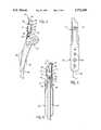
- FIG. 1is a front view of a preferred clamp assembly illustrating features of the present invention with a section of conductive jumper cable attached thereto;
- FIG. 2is a rear view of the clamp assembly
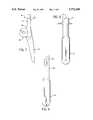
- FIG. 3is an exploded front view of the clamp assembly illustrating various components thereof
- FIG. 4is an enlarged front view of an active clamp member shown partially in section to illustrate the connection of a cable to a contact jaw;
- FIG. 5is a left side view of the active clamp member shown in FIG. 4 illustrating polarity markings on the exterior of a handle portion of the active clamp member;
- FIG. 6is a right side view of the active clamp member illustrating the connection of the cable to the contact jaw
- FIG. 7is a right side view of a passive clamp member of the clamp assembly
- FIG. 8is a left side view of the passive clamp member shown in FIG. 7;
- FIG. 9is a right side view of the passive clamp member
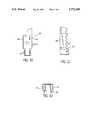
- FIG. 10is an enlarged side view of the contact jaw
- FIG. 11is a front view of the contact jaw shown in FIG. 10.
- FIG. 12is a top view of the contact jaw.
- FIGS. 1-3a clamp assembly 10 for removable attachment to a battery terminal (not shown). Although only one clamp assembly 10 is shown, it will be understood by those skilled in the art that four clamp assemblies 10 are provided in a typical jumper cable set, one at each end of two cables.
- the clamp assembly 10includes an active clamp member 12 pivotally attached to a passive clamp member 14 by a pivot pin or rivet 16.
- the active clamp member 12is of a one-piece construction defining a jaw portion 18 and a handle portion 20.
- the passive clamp member 14is similarly constructed with a jaw portion 22 and a handle portion 24.
- the active and passive clamp members 12 and 14are made of a metallic material and are entirely coated with a layer of non-conductive insulating material.
- the metallic materialis steel or similar metal, and the insulating material is a thin coating of PVC.
- a torsion spring 26is mounted about the rivet 16 (FIGS.
- the spring 26normally urges the handle portions 20, 24 apart and the jaw portions 18, 22 together. To force the jaw portions 18, 22 apart, a user grips the handle portions 20, 24 and forces them together.
- the rivet 16extends through spaced apart wing sections 30 on the active clamp member 12 and spaced apart wing sections 32 on the passive clamp member 14.
- the wing sections 30extend from between the jaw portion 18 and handle portion 20 of the active clamp member 12 toward the passive clamp member 14.
- the wing sections 32extend from between the jaw portion 22 and the handle portion 24 of the passive clamp member 14 toward the active clamp 12.
- a mechanical stop 34is also formed on each wing section 30 of the active clamp member 12 to limit the pivotal movement of the clamp members 12 and 14 relative to each other.
- the stops 34are adapted to contact corresponding edges 36 of the wing sections 32 on the passive clamp member 14 to prevent inadvertent contact between the jaw portions 18, 22 of the clamp members 12, 14. As best shown in FIG. 6, the stops 34 are preferably configured as flanges that extend inwardly in order to contact the wing section edges 36 of the passive clamp member 14.
- an electrically conductive contact jaw 40is secured interiorly of the jaw portion 18 of the active clamp member 12 (FIGS. 1-4 and 6).
- the contact jaw 40is made of copper-plated steel and is separately attached to the jaw portion 18 by a rivet 42 or similar fastener.
- a cable conductor 48which is associated with each clamp assembly 12, is connected directly to the contact jaw 40.
- the contact jaw 40has side walls 44 spaced apart approximately the same distance as side walls 46 of the active clamp member 12 to provide a close fit between the two parts (FIG. 6).
- the side walls 44 of the contact jaw 40also have serrated edges or teeth 47 formed thereon the to facilitate gripping securement to a battery terminal.
- the contact jaw 40is configured with a terminal end portion 50 capable of being crimped.
- the cable 48is a stranded copper cable having an end portion 52 that is crimped within the terminal end portion 50 of the contact jaw 40.
- An enlarged view of the contact jaw 40is illustrated in FIGS. 10-12.
- the jaw portion 22 of the passive clamp member 14defines serrated edges or teeth 54 which are coated with the insulating material.
- the conductive serrated edges 47 of the contact jaw 40 and the insulated serrated edges 54 of the passive clamp jaw portion 24cooperate under the action of the spring 26 to securely mount the cl amp assembly 10 to a battery terminal.
- the clamp assembly 12 of th e present inventionis also configure d to suppress or isolate conductive components of th e clamp assembly 12 to prevent sparking. More particularly, each conductive component of the clamp assembly 12 is shielded from contact with external electrically energized conductors. This protection is provided by recessing the contact jaw 40, the spring 26, and rivets 16 and 42 and all other assembly hardware below the major contacting surface of the insulated clamp members 12 and 14 or associated non-conductive hardware. Moreover, the coating of insulating material on both the active and passive clamp members 12 and 14 further prevent sparking.
- polarity markingsare either stamped on the clamp members 12 and 14 or affixed thereto on a label.
- the polarity markingscan constitute the symbols "+” or “-” or the words or abbreviations for "positive” or “negative”, or both.
- the markingscan also be colored in the conventional red to designate positive and black to designate negative polarity.
- markings 60are stamped on an exterior portion of the active clamp member 12 (FIGS. 1-5), and markings 62 are placed on the exterior of the passive clamp member 14 (FIG. 9).
- the polarity markings 62are made of a phosphorescent material to allow an operator to identify the markings in dim light.
- a cable assemblywhich directs the flow of boost current primarily through the contact jaw and prevents a short circuit through the passive jaw portion of the clamp assembly.
- the conductive components of the clampare shielded from contact with external electrically energized conductors to prevent sparking, and polarity markings are provided for ready identification of the polarity of the respective clamp assemblies.
Landscapes
- Connections By Means Of Piercing Elements, Nuts, Or Screws (AREA)
- Connection Of Batteries Or Terminals (AREA)
Abstract
Description
Claims (27)
Priority Applications (3)
| Application Number | Priority Date | Filing Date | Title |
|---|---|---|---|
| US08/723,218US5772468A (en) | 1996-09-27 | 1996-09-27 | Clamp assembly for a battery booster cable |
| CA002186925ACA2186925C (en) | 1996-09-27 | 1996-10-01 | Clamp assembly for a battery booster cable |
| MXPA/A/1997/007321AMXPA97007321A (en) | 1996-09-27 | 1997-09-25 | Clamp assembly or clamp for an acumula voltage elevator cable |
Applications Claiming Priority (2)
| Application Number | Priority Date | Filing Date | Title |
|---|---|---|---|
| US08/723,218US5772468A (en) | 1996-09-27 | 1996-09-27 | Clamp assembly for a battery booster cable |
| CA002186925ACA2186925C (en) | 1996-09-27 | 1996-10-01 | Clamp assembly for a battery booster cable |
Publications (1)
| Publication Number | Publication Date |
|---|---|
| US5772468Atrue US5772468A (en) | 1998-06-30 |
Family
ID=25678707
Family Applications (1)
| Application Number | Title | Priority Date | Filing Date |
|---|---|---|---|
| US08/723,218Expired - LifetimeUS5772468A (en) | 1996-09-27 | 1996-09-27 | Clamp assembly for a battery booster cable |
Country Status (2)
| Country | Link |
|---|---|
| US (1) | US5772468A (en) |
| CA (1) | CA2186925C (en) |
Cited By (126)
| Publication number | Priority date | Publication date | Assignee | Title |
|---|---|---|---|---|
| US20020109504A1 (en)* | 1999-09-01 | 2002-08-15 | Champlin Keith S. | Method and apparatus using a circuit model to evaluate cell/battery parameters |
| US20030025481A1 (en)* | 1997-11-03 | 2003-02-06 | Bertness Kevin I. | Energy management system for automotive vehicle |
| US20030164770A1 (en)* | 2000-07-29 | 2003-09-04 | Edge Ian James | Electrical resistance monitoring device |
| US6623314B1 (en)* | 2002-07-29 | 2003-09-23 | Midtronics, Inc. | Kelvin clamp for electrically coupling to a battery contact |
| US20040004318A1 (en)* | 2002-04-30 | 2004-01-08 | Klemens Degen | Suction cup device with spring action clamp clip |
| US6806716B2 (en) | 1999-04-08 | 2004-10-19 | Kevin I. Bertness | Electronic battery tester |
| US6850037B2 (en) | 1997-11-03 | 2005-02-01 | Midtronics, Inc. | In-vehicle battery monitor |
| US6885195B2 (en) | 1996-07-29 | 2005-04-26 | Midtronics, Inc. | Method and apparatus for auditing a battery test |
| US6886270B2 (en) | 2002-11-13 | 2005-05-03 | Diane L. Gilmer | Golf cart fan |
| US6906523B2 (en) | 2000-09-14 | 2005-06-14 | Midtronics, Inc. | Method and apparatus for testing cells and batteries embedded in series/parallel systems |
| US20050142929A1 (en)* | 2003-05-16 | 2005-06-30 | Cottle William C. | Portable power supply |
| DE10354080A1 (en)* | 2003-11-19 | 2005-06-30 | Daimlerchrysler Ag | Motor vehicle battery`s current/voltage measuring device, has pole pliers with shanks including two oppositely arranged arc-shaped gripping areas that contact outer contour of pole pin at contacting region of pin |
| US6913483B2 (en) | 2003-06-23 | 2005-07-05 | Midtronics, Inc. | Cable for electronic battery tester |
| US6914413B2 (en) | 1996-07-29 | 2005-07-05 | Midtronics, Inc. | Alternator tester with encoded output |
| US6933727B2 (en) | 2003-03-25 | 2005-08-23 | Midtronics, Inc. | Electronic battery tester cable |
| US6941234B2 (en) | 2001-10-17 | 2005-09-06 | Midtronics, Inc. | Query based electronic battery tester |
| US6967484B2 (en) | 2000-03-27 | 2005-11-22 | Midtronics, Inc. | Electronic battery tester with automotive scan tool communication |
| US6998847B2 (en) | 2000-03-27 | 2006-02-14 | Midtronics, Inc. | Electronic battery tester with data bus for removable module |
| US7003410B2 (en) | 1996-07-29 | 2006-02-21 | Midtronics, Inc. | Electronic battery tester with relative test output |
| US7003411B2 (en) | 1997-11-03 | 2006-02-21 | Midtronics, Inc. | Electronic battery tester with network communication |
| US20060125482A1 (en)* | 2004-12-09 | 2006-06-15 | Midtronics, Inc. | Apparatus and method for predicting battery capacity and fitness for service from a battery dynamic parameter and a recovery voltage differential |
| US7106070B2 (en) | 2004-07-22 | 2006-09-12 | Midtronics, Inc. | Broad-band low-inductance cables for making Kelvin connections to electrochemical cells and batteries |
| US7119686B2 (en) | 2004-04-13 | 2006-10-10 | Midtronics, Inc. | Theft prevention device for automotive vehicle service centers |
| US7126341B2 (en) | 1997-11-03 | 2006-10-24 | Midtronics, Inc. | Automotive vehicle electrical system diagnostic device |
| US7154276B2 (en) | 2003-09-05 | 2006-12-26 | Midtronics, Inc. | Method and apparatus for measuring a parameter of a vehicle electrical system |
| US7246015B2 (en) | 1996-07-29 | 2007-07-17 | Midtronics, Inc. | Alternator tester |
| US7319304B2 (en) | 2003-07-25 | 2008-01-15 | Midtronics, Inc. | Shunt connection to a PCB of an energy management system employed in an automotive vehicle |
| US7398176B2 (en) | 2000-03-27 | 2008-07-08 | Midtronics, Inc. | Battery testers with secondary functionality |
| US7408358B2 (en) | 2003-06-16 | 2008-08-05 | Midtronics, Inc. | Electronic battery tester having a user interface to configure a printer |
| US7422474B1 (en) | 2007-11-20 | 2008-09-09 | Good Mark D | Battery terminal clamping device |
| US7446536B2 (en) | 2000-03-27 | 2008-11-04 | Midtronics, Inc. | Scan tool for electronic battery tester |
| US7479763B2 (en) | 2001-06-22 | 2009-01-20 | Midtronics, Inc. | Apparatus and method for counteracting self discharge in a storage battery |
| US7498767B2 (en) | 2005-02-16 | 2009-03-03 | Midtronics, Inc. | Centralized data storage of condition of a storage battery at its point of sale |
| US7501795B2 (en) | 2001-06-22 | 2009-03-10 | Midtronics Inc. | Battery charger with booster pack |
| US7505856B2 (en) | 1999-04-08 | 2009-03-17 | Midtronics, Inc. | Battery test module |
| US7557586B1 (en) | 1999-11-01 | 2009-07-07 | Midtronics, Inc. | Electronic battery tester |
| US20090233495A1 (en)* | 2008-03-12 | 2009-09-17 | Sproesser George S | Booster Cable Clamp |
| US7595643B2 (en) | 2003-11-11 | 2009-09-29 | Midtronics, Inc. | Apparatus and method for simulating a battery tester with a fixed resistance load |
| US7598744B2 (en) | 2000-03-27 | 2009-10-06 | Midtronics, Inc. | Scan tool for electronic battery tester |
| US7598699B2 (en)* | 2004-02-20 | 2009-10-06 | Midtronics, Inc. | Replaceable clamp for electronic battery tester |
| US7598743B2 (en) | 2000-03-27 | 2009-10-06 | Midtronics, Inc. | Battery maintenance device having databus connection |
| US7619417B2 (en) | 2002-12-31 | 2009-11-17 | Midtronics, Inc. | Battery monitoring system |
| US7642786B2 (en) | 2004-06-01 | 2010-01-05 | Midtronics, Inc. | Battery tester capable of identifying faulty battery post adapters |
| US7688074B2 (en) | 1997-11-03 | 2010-03-30 | Midtronics, Inc. | Energy management system for automotive vehicle |
| US7705602B2 (en) | 1997-11-03 | 2010-04-27 | Midtronics, Inc. | Automotive vehicle electrical system diagnostic device |
| US7706991B2 (en) | 1996-07-29 | 2010-04-27 | Midtronics, Inc. | Alternator tester |
| US7710119B2 (en) | 2004-12-09 | 2010-05-04 | Midtronics, Inc. | Battery tester that calculates its own reference values |
| US7772850B2 (en) | 2004-07-12 | 2010-08-10 | Midtronics, Inc. | Wireless battery tester with information encryption means |
| US7774151B2 (en) | 1997-11-03 | 2010-08-10 | Midtronics, Inc. | Wireless battery monitor |
| US7777612B2 (en) | 2004-04-13 | 2010-08-17 | Midtronics, Inc. | Theft prevention device for automotive vehicle service centers |
| CN101814663A (en)* | 2010-04-02 | 2010-08-25 | 上海广为电器工具有限公司 | High conductivity energy saving clamp |
| US7791348B2 (en) | 2007-02-27 | 2010-09-07 | Midtronics, Inc. | Battery tester with promotion feature to promote use of the battery tester by providing the user with codes having redeemable value |
| US7808375B2 (en) | 2007-04-16 | 2010-10-05 | Midtronics, Inc. | Battery run down indicator |
| US20100304621A1 (en)* | 2009-06-02 | 2010-12-02 | Carrand Companies, Inc. | Jumper Cable Clamp |
| US7977914B2 (en) | 2003-10-08 | 2011-07-12 | Midtronics, Inc. | Battery maintenance tool with probe light |
| US8164343B2 (en) | 2003-09-05 | 2012-04-24 | Midtronics, Inc. | Method and apparatus for measuring a parameter of a vehicle electrical system |
| US8198900B2 (en) | 1996-07-29 | 2012-06-12 | Midtronics, Inc. | Automotive battery charging system tester |
| US8203345B2 (en) | 2007-12-06 | 2012-06-19 | Midtronics, Inc. | Storage battery and battery tester |
| WO2012094494A1 (en)* | 2011-01-05 | 2012-07-12 | Exelon Generation Company, Llc | Insulated electrode cover a welding electrode holder |
| US8306690B2 (en) | 2007-07-17 | 2012-11-06 | Midtronics, Inc. | Battery tester for electric vehicle |
| US8344685B2 (en) | 2004-08-20 | 2013-01-01 | Midtronics, Inc. | System for automatically gathering battery information |
| US8436619B2 (en) | 2004-08-20 | 2013-05-07 | Midtronics, Inc. | Integrated tag reader and environment sensor |
| US8442877B2 (en) | 2004-08-20 | 2013-05-14 | Midtronics, Inc. | Simplification of inventory management |
| US8476913B2 (en) | 2007-05-17 | 2013-07-02 | Newson Gale Limited | Improvements relating to the testing of an earth connection |
| US8513949B2 (en) | 2000-03-27 | 2013-08-20 | Midtronics, Inc. | Electronic battery tester or charger with databus connection |
| US8738309B2 (en) | 2010-09-30 | 2014-05-27 | Midtronics, Inc. | Battery pack maintenance for electric vehicles |
| US8872517B2 (en) | 1996-07-29 | 2014-10-28 | Midtronics, Inc. | Electronic battery tester with battery age input |
| US8958998B2 (en) | 1997-11-03 | 2015-02-17 | Midtronics, Inc. | Electronic battery tester with network communication |
| US9018958B2 (en) | 2003-09-05 | 2015-04-28 | Midtronics, Inc. | Method and apparatus for measuring a parameter of a vehicle electrical system |
| WO2015121631A1 (en)* | 2014-02-11 | 2015-08-20 | Megger Instruments Ltd | Electrical connection apparatus |
| US9201120B2 (en) | 2010-08-12 | 2015-12-01 | Midtronics, Inc. | Electronic battery tester for testing storage battery |
| US9225112B2 (en)* | 2011-01-07 | 2015-12-29 | Apple Inc. | Portable user device with a clip having electrical terminals |
| US9229062B2 (en) | 2010-05-27 | 2016-01-05 | Midtronics, Inc. | Electronic storage battery diagnostic system |
| US20160020536A1 (en)* | 2014-07-18 | 2016-01-21 | Yazaki Corporation | Booster cable holding structure |
| US9244100B2 (en) | 2013-03-15 | 2016-01-26 | Midtronics, Inc. | Current clamp with jaw closure detection |
| US9255955B2 (en) | 2003-09-05 | 2016-02-09 | Midtronics, Inc. | Method and apparatus for measuring a parameter of a vehicle electrical system |
| US9274157B2 (en) | 2007-07-17 | 2016-03-01 | Midtronics, Inc. | Battery tester for electric vehicle |
| US9312575B2 (en) | 2013-05-16 | 2016-04-12 | Midtronics, Inc. | Battery testing system and method |
| US20160197415A1 (en)* | 2015-01-05 | 2016-07-07 | Twitch Technologies Llc | Safe jumper methodology utilizing switch embedded connection clamps |
| US9419311B2 (en) | 2010-06-18 | 2016-08-16 | Midtronics, Inc. | Battery maintenance device with thermal buffer |
| US9425487B2 (en) | 2010-03-03 | 2016-08-23 | Midtronics, Inc. | Monitor for front terminal batteries |
| US9496720B2 (en) | 2004-08-20 | 2016-11-15 | Midtronics, Inc. | System for automatically gathering battery information |
| US20170054232A1 (en)* | 2015-08-18 | 2017-02-23 | Gerard M. Toscani | Jumper clamps |
| US9588185B2 (en) | 2010-02-25 | 2017-03-07 | Keith S. Champlin | Method and apparatus for detecting cell deterioration in an electrochemical cell or battery |
| US9851411B2 (en) | 2012-06-28 | 2017-12-26 | Keith S. Champlin | Suppressing HF cable oscillations during dynamic measurements of cells and batteries |
| US9923289B2 (en) | 2014-01-16 | 2018-03-20 | Midtronics, Inc. | Battery clamp with endoskeleton design |
| US9966676B2 (en) | 2015-09-28 | 2018-05-08 | Midtronics, Inc. | Kelvin connector adapter for storage battery |
| US10046649B2 (en) | 2012-06-28 | 2018-08-14 | Midtronics, Inc. | Hybrid and electric vehicle battery pack maintenance device |
| US10222397B2 (en) | 2014-09-26 | 2019-03-05 | Midtronics, Inc. | Cable connector for electronic battery tester |
| CN109668821A (en)* | 2019-02-20 | 2019-04-23 | 西北工业大学 | A kind of treadmill test part measured material for high-low-temperature environmental testing case |
| US10317468B2 (en) | 2015-01-26 | 2019-06-11 | Midtronics, Inc. | Alternator tester |
| US10429449B2 (en) | 2011-11-10 | 2019-10-01 | Midtronics, Inc. | Battery pack tester |
| US10473555B2 (en) | 2014-07-14 | 2019-11-12 | Midtronics, Inc. | Automotive maintenance system |
| US10608353B2 (en) | 2016-06-28 | 2020-03-31 | Midtronics, Inc. | Battery clamp |
| CN111742229A (en)* | 2019-01-24 | 2020-10-02 | 株式会社Lg化学 | Battery Performance Measurement Equipment |
| WO2020214519A1 (en)* | 2019-04-16 | 2020-10-22 | The Noco Company | Battery clamp device |
| US10843574B2 (en) | 2013-12-12 | 2020-11-24 | Midtronics, Inc. | Calibration and programming of in-vehicle battery sensors |
| US11054480B2 (en) | 2016-10-25 | 2021-07-06 | Midtronics, Inc. | Electrical load for electronic battery tester and electronic battery tester including such electrical load |
| USD933605S1 (en)* | 2018-10-03 | 2021-10-19 | The Noco Company | Battery clamp |
| USD934804S1 (en)* | 2018-09-28 | 2021-11-02 | The Noco Company | Battery clamp |
| US11325479B2 (en) | 2012-06-28 | 2022-05-10 | Midtronics, Inc. | Hybrid and electric vehicle battery maintenance device |
| US11474153B2 (en) | 2019-11-12 | 2022-10-18 | Midtronics, Inc. | Battery pack maintenance system |
| US11486930B2 (en) | 2020-01-23 | 2022-11-01 | Midtronics, Inc. | Electronic battery tester with battery clamp storage holsters |
| US11513160B2 (en) | 2018-11-29 | 2022-11-29 | Midtronics, Inc. | Vehicle battery maintenance device |
| US11545839B2 (en) | 2019-11-05 | 2023-01-03 | Midtronics, Inc. | System for charging a series of connected batteries |
| US11566972B2 (en) | 2019-07-31 | 2023-01-31 | Midtronics, Inc. | Tire tread gauge using visual indicator |
| US11630126B2 (en)* | 2018-06-12 | 2023-04-18 | Chroma Ate Inc. | Clipped testing device having a flexible conducting member |
| USD984381S1 (en) | 2020-11-25 | 2023-04-25 | The Noco Company | Battery cable assembly for jump starting device |
| US11650259B2 (en) | 2010-06-03 | 2023-05-16 | Midtronics, Inc. | Battery pack maintenance for electric vehicle |
| US11668779B2 (en) | 2019-11-11 | 2023-06-06 | Midtronics, Inc. | Hybrid and electric vehicle battery pack maintenance device |
| USD988999S1 (en) | 2018-10-03 | 2023-06-13 | The Noco Company | Battery clamp |
| USD991177S1 (en) | 2018-10-01 | 2023-07-04 | The Noco Company | Battery clamp |
| USD991186S1 (en) | 2020-12-11 | 2023-07-04 | The Noco Company | Battery cable assembly |
| USD991185S1 (en) | 2020-12-11 | 2023-07-04 | The Noco Company | Battery cable assembly |
| US11740294B2 (en) | 2010-06-03 | 2023-08-29 | Midtronics, Inc. | High use battery pack maintenance |
| USD997102S1 (en) | 2018-10-03 | 2023-08-29 | The Noco Company | Battery clamp |
| USD1004550S1 (en) | 2018-10-03 | 2023-11-14 | The Noco Company | Battery clamp |
| US11973202B2 (en) | 2019-12-31 | 2024-04-30 | Midtronics, Inc. | Intelligent module interface for battery maintenance device |
| US12070978B1 (en)* | 2019-08-01 | 2024-08-27 | Wade Rathmell | Jumpstart system and method of use |
| EP4492580A1 (en)* | 2023-07-11 | 2025-01-15 | Illinois Tool Works Inc. | Electrically insulated hand clamps |
| US12237482B2 (en) | 2019-12-31 | 2025-02-25 | Midtronics, Inc. | Intelligent module interface for battery maintenance device |
| USD1063845S1 (en) | 2018-10-01 | 2025-02-25 | The Noco Company | Battery clamp |
| USD1067187S1 (en) | 2018-10-05 | 2025-03-18 | The Noco Company | Battery clamp |
| US12320857B2 (en) | 2016-10-25 | 2025-06-03 | Midtronics, Inc. | Electrical load for electronic battery tester and electronic battery tester including such electrical load |
| US12330513B2 (en) | 2022-02-14 | 2025-06-17 | Midtronics, Inc. | Battery maintenance device with high voltage connector |
| US12392833B2 (en) | 2022-05-09 | 2025-08-19 | Midtronics, Inc. | Electronic battery tester |
Citations (9)
| Publication number | Priority date | Publication date | Assignee | Title |
|---|---|---|---|---|
| US4449772A (en)* | 1982-09-17 | 1984-05-22 | Cooper Industries, Inc. | Electrical connector for top and side mount battery terminals |
| US4453791A (en)* | 1982-09-17 | 1984-06-12 | Cooper Industries, Inc. | Booster cable clamp for side terminal and standard battery posts |
| US4685760A (en)* | 1986-02-24 | 1987-08-11 | Mize Max D | Booster handle |
| US4826457A (en)* | 1988-05-26 | 1989-05-02 | Carol Cable Company, Inc. | Clamp for battery booster cable |
| US4923415A (en)* | 1989-05-11 | 1990-05-08 | Lee Kuo Shu | Structure of jumper cable clamp |
| US4929199A (en)* | 1988-07-13 | 1990-05-29 | Ferret | Battery cable clip and cable connection |
| US4934957A (en)* | 1989-08-15 | 1990-06-19 | Bellusci Albert V | Automotive battery terminal clamp for a battery jumper cable |
| US5002508A (en)* | 1989-09-01 | 1991-03-26 | American Consolidated Enterprises, Inc. | Multiple battery terminal connector |
| US5021008A (en)* | 1990-06-19 | 1991-06-04 | Scherer Peter J | Tangle free manually engageable device |
- 1996
- 1996-09-27USUS08/723,218patent/US5772468A/ennot_activeExpired - Lifetime
- 1996-10-01CACA002186925Apatent/CA2186925C/ennot_activeExpired - Lifetime
Patent Citations (9)
| Publication number | Priority date | Publication date | Assignee | Title |
|---|---|---|---|---|
| US4449772A (en)* | 1982-09-17 | 1984-05-22 | Cooper Industries, Inc. | Electrical connector for top and side mount battery terminals |
| US4453791A (en)* | 1982-09-17 | 1984-06-12 | Cooper Industries, Inc. | Booster cable clamp for side terminal and standard battery posts |
| US4685760A (en)* | 1986-02-24 | 1987-08-11 | Mize Max D | Booster handle |
| US4826457A (en)* | 1988-05-26 | 1989-05-02 | Carol Cable Company, Inc. | Clamp for battery booster cable |
| US4929199A (en)* | 1988-07-13 | 1990-05-29 | Ferret | Battery cable clip and cable connection |
| US4923415A (en)* | 1989-05-11 | 1990-05-08 | Lee Kuo Shu | Structure of jumper cable clamp |
| US4934957A (en)* | 1989-08-15 | 1990-06-19 | Bellusci Albert V | Automotive battery terminal clamp for a battery jumper cable |
| US5002508A (en)* | 1989-09-01 | 1991-03-26 | American Consolidated Enterprises, Inc. | Multiple battery terminal connector |
| US5021008A (en)* | 1990-06-19 | 1991-06-04 | Scherer Peter J | Tangle free manually engageable device |
Cited By (173)
| Publication number | Priority date | Publication date | Assignee | Title |
|---|---|---|---|---|
| US8872517B2 (en) | 1996-07-29 | 2014-10-28 | Midtronics, Inc. | Electronic battery tester with battery age input |
| US7295936B2 (en) | 1996-07-29 | 2007-11-13 | Midtronics, Inc. | Electronic battery tester with relative test output |
| US7003410B2 (en) | 1996-07-29 | 2006-02-21 | Midtronics, Inc. | Electronic battery tester with relative test output |
| US8198900B2 (en) | 1996-07-29 | 2012-06-12 | Midtronics, Inc. | Automotive battery charging system tester |
| US7656162B2 (en) | 1996-07-29 | 2010-02-02 | Midtronics Inc. | Electronic battery tester with vehicle type input |
| US7706991B2 (en) | 1996-07-29 | 2010-04-27 | Midtronics, Inc. | Alternator tester |
| US6914413B2 (en) | 1996-07-29 | 2005-07-05 | Midtronics, Inc. | Alternator tester with encoded output |
| US7246015B2 (en) | 1996-07-29 | 2007-07-17 | Midtronics, Inc. | Alternator tester |
| US6885195B2 (en) | 1996-07-29 | 2005-04-26 | Midtronics, Inc. | Method and apparatus for auditing a battery test |
| US7940052B2 (en) | 1996-07-29 | 2011-05-10 | Midtronics, Inc. | Electronic battery test based upon battery requirements |
| US7774151B2 (en) | 1997-11-03 | 2010-08-10 | Midtronics, Inc. | Wireless battery monitor |
| US7642787B2 (en) | 1997-11-03 | 2010-01-05 | Midtronics Inc. | Automotive vehicle electrical system diagnostic device |
| US6850037B2 (en) | 1997-11-03 | 2005-02-01 | Midtronics, Inc. | In-vehicle battery monitor |
| US8958998B2 (en) | 1997-11-03 | 2015-02-17 | Midtronics, Inc. | Electronic battery tester with network communication |
| US7126341B2 (en) | 1997-11-03 | 2006-10-24 | Midtronics, Inc. | Automotive vehicle electrical system diagnostic device |
| US7999505B2 (en) | 1997-11-03 | 2011-08-16 | Midtronics, Inc. | In-vehicle battery monitor |
| US7705602B2 (en) | 1997-11-03 | 2010-04-27 | Midtronics, Inc. | Automotive vehicle electrical system diagnostic device |
| US7688074B2 (en) | 1997-11-03 | 2010-03-30 | Midtronics, Inc. | Energy management system for automotive vehicle |
| US8674654B2 (en) | 1997-11-03 | 2014-03-18 | Midtronics, Inc. | In-vehicle battery monitor |
| US20030025481A1 (en)* | 1997-11-03 | 2003-02-06 | Bertness Kevin I. | Energy management system for automotive vehicle |
| US8493022B2 (en) | 1997-11-03 | 2013-07-23 | Midtronics, Inc. | Automotive vehicle electrical system diagnostic device |
| US7003411B2 (en) | 1997-11-03 | 2006-02-21 | Midtronics, Inc. | Electronic battery tester with network communication |
| US7505856B2 (en) | 1999-04-08 | 2009-03-17 | Midtronics, Inc. | Battery test module |
| US6806716B2 (en) | 1999-04-08 | 2004-10-19 | Kevin I. Bertness | Electronic battery tester |
| US20020109504A1 (en)* | 1999-09-01 | 2002-08-15 | Champlin Keith S. | Method and apparatus using a circuit model to evaluate cell/battery parameters |
| US7557586B1 (en) | 1999-11-01 | 2009-07-07 | Midtronics, Inc. | Electronic battery tester |
| US8754653B2 (en) | 1999-11-01 | 2014-06-17 | Midtronics, Inc. | Electronic battery tester |
| US9052366B2 (en) | 2000-03-27 | 2015-06-09 | Midtronics, Inc. | Battery testers with secondary functionality |
| US8872516B2 (en) | 2000-03-27 | 2014-10-28 | Midtronics, Inc. | Electronic battery tester mounted in a vehicle |
| US8237448B2 (en) | 2000-03-27 | 2012-08-07 | Midtronics, Inc. | Battery testers with secondary functionality |
| US7598743B2 (en) | 2000-03-27 | 2009-10-06 | Midtronics, Inc. | Battery maintenance device having databus connection |
| US8513949B2 (en) | 2000-03-27 | 2013-08-20 | Midtronics, Inc. | Electronic battery tester or charger with databus connection |
| US7924015B2 (en) | 2000-03-27 | 2011-04-12 | Midtronics, Inc. | Automotive vehicle battery test system |
| US7398176B2 (en) | 2000-03-27 | 2008-07-08 | Midtronics, Inc. | Battery testers with secondary functionality |
| US7598744B2 (en) | 2000-03-27 | 2009-10-06 | Midtronics, Inc. | Scan tool for electronic battery tester |
| US7728597B2 (en) | 2000-03-27 | 2010-06-01 | Midtronics, Inc. | Electronic battery tester with databus |
| US6998847B2 (en) | 2000-03-27 | 2006-02-14 | Midtronics, Inc. | Electronic battery tester with data bus for removable module |
| US7446536B2 (en) | 2000-03-27 | 2008-11-04 | Midtronics, Inc. | Scan tool for electronic battery tester |
| US6967484B2 (en) | 2000-03-27 | 2005-11-22 | Midtronics, Inc. | Electronic battery tester with automotive scan tool communication |
| US6924740B2 (en)* | 2000-07-29 | 2005-08-02 | Newson Gale Limited | Electrical resistance monitoring device |
| US20030164770A1 (en)* | 2000-07-29 | 2003-09-04 | Edge Ian James | Electrical resistance monitoring device |
| US6906523B2 (en) | 2000-09-14 | 2005-06-14 | Midtronics, Inc. | Method and apparatus for testing cells and batteries embedded in series/parallel systems |
| US7501795B2 (en) | 2001-06-22 | 2009-03-10 | Midtronics Inc. | Battery charger with booster pack |
| US7479763B2 (en) | 2001-06-22 | 2009-01-20 | Midtronics, Inc. | Apparatus and method for counteracting self discharge in a storage battery |
| US7034541B2 (en) | 2001-10-17 | 2006-04-25 | Midtronics, Inc. | Query based electronic battery tester |
| US6941234B2 (en) | 2001-10-17 | 2005-09-06 | Midtronics, Inc. | Query based electronic battery tester |
| US7363175B2 (en) | 2001-10-17 | 2008-04-22 | Midtronics, Inc. | Query based electronic battery tester |
| US6799756B2 (en) | 2002-04-30 | 2004-10-05 | Wolfcraft Gmbh | Suction cup device with spring action clamp clip |
| US20040004318A1 (en)* | 2002-04-30 | 2004-01-08 | Klemens Degen | Suction cup device with spring action clamp clip |
| US6623314B1 (en)* | 2002-07-29 | 2003-09-23 | Midtronics, Inc. | Kelvin clamp for electrically coupling to a battery contact |
| US6886270B2 (en) | 2002-11-13 | 2005-05-03 | Diane L. Gilmer | Golf cart fan |
| US7619417B2 (en) | 2002-12-31 | 2009-11-17 | Midtronics, Inc. | Battery monitoring system |
| US6933727B2 (en) | 2003-03-25 | 2005-08-23 | Midtronics, Inc. | Electronic battery tester cable |
| US7252558B2 (en)* | 2003-05-16 | 2007-08-07 | Associated Equipment Corporation | Portable power supply |
| US20050142929A1 (en)* | 2003-05-16 | 2005-06-30 | Cottle William C. | Portable power supply |
| US7408358B2 (en) | 2003-06-16 | 2008-08-05 | Midtronics, Inc. | Electronic battery tester having a user interface to configure a printer |
| US6913483B2 (en) | 2003-06-23 | 2005-07-05 | Midtronics, Inc. | Cable for electronic battery tester |
| US7319304B2 (en) | 2003-07-25 | 2008-01-15 | Midtronics, Inc. | Shunt connection to a PCB of an energy management system employed in an automotive vehicle |
| US9255955B2 (en) | 2003-09-05 | 2016-02-09 | Midtronics, Inc. | Method and apparatus for measuring a parameter of a vehicle electrical system |
| US8674711B2 (en) | 2003-09-05 | 2014-03-18 | Midtronics, Inc. | Method and apparatus for measuring a parameter of a vehicle electrical system |
| US8164343B2 (en) | 2003-09-05 | 2012-04-24 | Midtronics, Inc. | Method and apparatus for measuring a parameter of a vehicle electrical system |
| US9018958B2 (en) | 2003-09-05 | 2015-04-28 | Midtronics, Inc. | Method and apparatus for measuring a parameter of a vehicle electrical system |
| US7154276B2 (en) | 2003-09-05 | 2006-12-26 | Midtronics, Inc. | Method and apparatus for measuring a parameter of a vehicle electrical system |
| US7977914B2 (en) | 2003-10-08 | 2011-07-12 | Midtronics, Inc. | Battery maintenance tool with probe light |
| US7595643B2 (en) | 2003-11-11 | 2009-09-29 | Midtronics, Inc. | Apparatus and method for simulating a battery tester with a fixed resistance load |
| DE10354080A1 (en)* | 2003-11-19 | 2005-06-30 | Daimlerchrysler Ag | Motor vehicle battery`s current/voltage measuring device, has pole pliers with shanks including two oppositely arranged arc-shaped gripping areas that contact outer contour of pole pin at contacting region of pin |
| US7598699B2 (en)* | 2004-02-20 | 2009-10-06 | Midtronics, Inc. | Replaceable clamp for electronic battery tester |
| US7777612B2 (en) | 2004-04-13 | 2010-08-17 | Midtronics, Inc. | Theft prevention device for automotive vehicle service centers |
| US7119686B2 (en) | 2004-04-13 | 2006-10-10 | Midtronics, Inc. | Theft prevention device for automotive vehicle service centers |
| US7642786B2 (en) | 2004-06-01 | 2010-01-05 | Midtronics, Inc. | Battery tester capable of identifying faulty battery post adapters |
| US7772850B2 (en) | 2004-07-12 | 2010-08-10 | Midtronics, Inc. | Wireless battery tester with information encryption means |
| US7425833B2 (en) | 2004-07-22 | 2008-09-16 | Midtronics, Inc. | Broad-band low-inductance cables for making Kelvin connections to electrochemical cells and batteries |
| US7106070B2 (en) | 2004-07-22 | 2006-09-12 | Midtronics, Inc. | Broad-band low-inductance cables for making Kelvin connections to electrochemical cells and batteries |
| US8436619B2 (en) | 2004-08-20 | 2013-05-07 | Midtronics, Inc. | Integrated tag reader and environment sensor |
| US8963550B2 (en) | 2004-08-20 | 2015-02-24 | Midtronics, Inc. | System for automatically gathering battery information |
| US8704483B2 (en) | 2004-08-20 | 2014-04-22 | Midtronics, Inc. | System for automatically gathering battery information |
| US9496720B2 (en) | 2004-08-20 | 2016-11-15 | Midtronics, Inc. | System for automatically gathering battery information |
| US8442877B2 (en) | 2004-08-20 | 2013-05-14 | Midtronics, Inc. | Simplification of inventory management |
| US8344685B2 (en) | 2004-08-20 | 2013-01-01 | Midtronics, Inc. | System for automatically gathering battery information |
| US7545146B2 (en) | 2004-12-09 | 2009-06-09 | Midtronics, Inc. | Apparatus and method for predicting battery capacity and fitness for service from a battery dynamic parameter and a recovery voltage differential |
| US7710119B2 (en) | 2004-12-09 | 2010-05-04 | Midtronics, Inc. | Battery tester that calculates its own reference values |
| US20060125482A1 (en)* | 2004-12-09 | 2006-06-15 | Midtronics, Inc. | Apparatus and method for predicting battery capacity and fitness for service from a battery dynamic parameter and a recovery voltage differential |
| US7498767B2 (en) | 2005-02-16 | 2009-03-03 | Midtronics, Inc. | Centralized data storage of condition of a storage battery at its point of sale |
| US7940053B2 (en) | 2007-02-27 | 2011-05-10 | Midtronics, Inc. | Battery tester with promotion feature |
| US7791348B2 (en) | 2007-02-27 | 2010-09-07 | Midtronics, Inc. | Battery tester with promotion feature to promote use of the battery tester by providing the user with codes having redeemable value |
| US7808375B2 (en) | 2007-04-16 | 2010-10-05 | Midtronics, Inc. | Battery run down indicator |
| US8476913B2 (en) | 2007-05-17 | 2013-07-02 | Newson Gale Limited | Improvements relating to the testing of an earth connection |
| US9335362B2 (en) | 2007-07-17 | 2016-05-10 | Midtronics, Inc. | Battery tester for electric vehicle |
| US9274157B2 (en) | 2007-07-17 | 2016-03-01 | Midtronics, Inc. | Battery tester for electric vehicle |
| US8306690B2 (en) | 2007-07-17 | 2012-11-06 | Midtronics, Inc. | Battery tester for electric vehicle |
| US7422474B1 (en) | 2007-11-20 | 2008-09-09 | Good Mark D | Battery terminal clamping device |
| US8203345B2 (en) | 2007-12-06 | 2012-06-19 | Midtronics, Inc. | Storage battery and battery tester |
| US7736200B2 (en)* | 2008-03-12 | 2010-06-15 | East Penn Manufacturing Co., Inc. | Booster cable clamp |
| US20090233495A1 (en)* | 2008-03-12 | 2009-09-17 | Sproesser George S | Booster Cable Clamp |
| US20100304621A1 (en)* | 2009-06-02 | 2010-12-02 | Carrand Companies, Inc. | Jumper Cable Clamp |
| US8083555B2 (en) | 2009-06-02 | 2011-12-27 | Hopkins Manufacturing Corporation | Jumper cable clamp |
| US9588185B2 (en) | 2010-02-25 | 2017-03-07 | Keith S. Champlin | Method and apparatus for detecting cell deterioration in an electrochemical cell or battery |
| US9425487B2 (en) | 2010-03-03 | 2016-08-23 | Midtronics, Inc. | Monitor for front terminal batteries |
| CN101814663A (en)* | 2010-04-02 | 2010-08-25 | 上海广为电器工具有限公司 | High conductivity energy saving clamp |
| US9229062B2 (en) | 2010-05-27 | 2016-01-05 | Midtronics, Inc. | Electronic storage battery diagnostic system |
| US11740294B2 (en) | 2010-06-03 | 2023-08-29 | Midtronics, Inc. | High use battery pack maintenance |
| US11650259B2 (en) | 2010-06-03 | 2023-05-16 | Midtronics, Inc. | Battery pack maintenance for electric vehicle |
| US12196813B2 (en) | 2010-06-03 | 2025-01-14 | Midtronics, Inc. | High use battery pack maintenance |
| US9419311B2 (en) | 2010-06-18 | 2016-08-16 | Midtronics, Inc. | Battery maintenance device with thermal buffer |
| US9201120B2 (en) | 2010-08-12 | 2015-12-01 | Midtronics, Inc. | Electronic battery tester for testing storage battery |
| US8738309B2 (en) | 2010-09-30 | 2014-05-27 | Midtronics, Inc. | Battery pack maintenance for electric vehicles |
| US12005534B2 (en) | 2011-01-05 | 2024-06-11 | Constellation Energy Generation, Llc | Insulated electrode cover for a welding electrode holder |
| WO2012094494A1 (en)* | 2011-01-05 | 2012-07-12 | Exelon Generation Company, Llc | Insulated electrode cover a welding electrode holder |
| US9225112B2 (en)* | 2011-01-07 | 2015-12-29 | Apple Inc. | Portable user device with a clip having electrical terminals |
| US10429449B2 (en) | 2011-11-10 | 2019-10-01 | Midtronics, Inc. | Battery pack tester |
| US11325479B2 (en) | 2012-06-28 | 2022-05-10 | Midtronics, Inc. | Hybrid and electric vehicle battery maintenance device |
| US11548404B2 (en) | 2012-06-28 | 2023-01-10 | Midtronics, Inc. | Hybrid and electric vehicle battery pack maintenance device |
| US11926224B2 (en) | 2012-06-28 | 2024-03-12 | Midtronics, Inc. | Hybrid and electric vehicle battery pack maintenance device |
| US10046649B2 (en) | 2012-06-28 | 2018-08-14 | Midtronics, Inc. | Hybrid and electric vehicle battery pack maintenance device |
| US9851411B2 (en) | 2012-06-28 | 2017-12-26 | Keith S. Champlin | Suppressing HF cable oscillations during dynamic measurements of cells and batteries |
| US9244100B2 (en) | 2013-03-15 | 2016-01-26 | Midtronics, Inc. | Current clamp with jaw closure detection |
| US9312575B2 (en) | 2013-05-16 | 2016-04-12 | Midtronics, Inc. | Battery testing system and method |
| US10843574B2 (en) | 2013-12-12 | 2020-11-24 | Midtronics, Inc. | Calibration and programming of in-vehicle battery sensors |
| US9923289B2 (en) | 2014-01-16 | 2018-03-20 | Midtronics, Inc. | Battery clamp with endoskeleton design |
| US9819113B2 (en)* | 2014-02-11 | 2017-11-14 | Megger Instruments Ltd | Electrical connection apparatus |
| US20160352037A1 (en)* | 2014-02-11 | 2016-12-01 | Megger Instruments Ltd | Electrical connection apparatus |
| WO2015121631A1 (en)* | 2014-02-11 | 2015-08-20 | Megger Instruments Ltd | Electrical connection apparatus |
| US10473555B2 (en) | 2014-07-14 | 2019-11-12 | Midtronics, Inc. | Automotive maintenance system |
| US9592778B2 (en)* | 2014-07-18 | 2017-03-14 | Yazaki Corporation | Booster cable holding structure |
| US20160020536A1 (en)* | 2014-07-18 | 2016-01-21 | Yazaki Corporation | Booster cable holding structure |
| US10222397B2 (en) | 2014-09-26 | 2019-03-05 | Midtronics, Inc. | Cable connector for electronic battery tester |
| US9692154B2 (en)* | 2015-01-05 | 2017-06-27 | Twitch Technologies Llc | Safe jumper methodology utilizing switch embedded connection clamps |
| US20160197415A1 (en)* | 2015-01-05 | 2016-07-07 | Twitch Technologies Llc | Safe jumper methodology utilizing switch embedded connection clamps |
| US10317468B2 (en) | 2015-01-26 | 2019-06-11 | Midtronics, Inc. | Alternator tester |
| US20170054232A1 (en)* | 2015-08-18 | 2017-02-23 | Gerard M. Toscani | Jumper clamps |
| US9692155B2 (en)* | 2015-08-18 | 2017-06-27 | Paris Business Products, Inc. | Jumper clamps |
| US9966676B2 (en) | 2015-09-28 | 2018-05-08 | Midtronics, Inc. | Kelvin connector adapter for storage battery |
| US10608353B2 (en) | 2016-06-28 | 2020-03-31 | Midtronics, Inc. | Battery clamp |
| US11054480B2 (en) | 2016-10-25 | 2021-07-06 | Midtronics, Inc. | Electrical load for electronic battery tester and electronic battery tester including such electrical load |
| US12320857B2 (en) | 2016-10-25 | 2025-06-03 | Midtronics, Inc. | Electrical load for electronic battery tester and electronic battery tester including such electrical load |
| US11630126B2 (en)* | 2018-06-12 | 2023-04-18 | Chroma Ate Inc. | Clipped testing device having a flexible conducting member |
| USD934804S1 (en)* | 2018-09-28 | 2021-11-02 | The Noco Company | Battery clamp |
| USD991177S1 (en) | 2018-10-01 | 2023-07-04 | The Noco Company | Battery clamp |
| USD1066252S1 (en) | 2018-10-01 | 2025-03-11 | The Noco Company | Battery clamp |
| USD1063845S1 (en) | 2018-10-01 | 2025-02-25 | The Noco Company | Battery clamp |
| USD1093314S1 (en) | 2018-10-03 | 2025-09-16 | The Noco Company | Battery clamp |
| USD993920S1 (en) | 2018-10-03 | 2023-08-01 | The Noco Company | Battery clamp |
| USD1055859S1 (en) | 2018-10-03 | 2024-12-31 | The Noco Company | Battery clamp |
| USD1004550S1 (en) | 2018-10-03 | 2023-11-14 | The Noco Company | Battery clamp |
| USD988999S1 (en) | 2018-10-03 | 2023-06-13 | The Noco Company | Battery clamp |
| USD1003833S1 (en) | 2018-10-03 | 2023-11-07 | The Noco Company | Battery clamp |
| USD997102S1 (en) | 2018-10-03 | 2023-08-29 | The Noco Company | Battery clamp |
| USD933605S1 (en)* | 2018-10-03 | 2021-10-19 | The Noco Company | Battery clamp |
| USD1067187S1 (en) | 2018-10-05 | 2025-03-18 | The Noco Company | Battery clamp |
| US11513160B2 (en) | 2018-11-29 | 2022-11-29 | Midtronics, Inc. | Vehicle battery maintenance device |
| CN111742229A (en)* | 2019-01-24 | 2020-10-02 | 株式会社Lg化学 | Battery Performance Measurement Equipment |
| CN111742229B (en)* | 2019-01-24 | 2023-06-16 | 株式会社Lg新能源 | Battery Performance Measurement Equipment |
| CN109668821A (en)* | 2019-02-20 | 2019-04-23 | 西北工业大学 | A kind of treadmill test part measured material for high-low-temperature environmental testing case |
| US11764501B2 (en) | 2019-04-16 | 2023-09-19 | The Noco Company | Battery clamp device |
| GB2596997B (en)* | 2019-04-16 | 2023-10-04 | Noco Co | Battery clamp device |
| WO2020214519A1 (en)* | 2019-04-16 | 2020-10-22 | The Noco Company | Battery clamp device |
| GB2596997A (en)* | 2019-04-16 | 2022-01-12 | Noco Co | Battery clamp device |
| US11621506B2 (en) | 2019-04-16 | 2023-04-04 | The Noco Company | Battery clamp device |
| US11566972B2 (en) | 2019-07-31 | 2023-01-31 | Midtronics, Inc. | Tire tread gauge using visual indicator |
| US12070978B1 (en)* | 2019-08-01 | 2024-08-27 | Wade Rathmell | Jumpstart system and method of use |
| US11545839B2 (en) | 2019-11-05 | 2023-01-03 | Midtronics, Inc. | System for charging a series of connected batteries |
| US11668779B2 (en) | 2019-11-11 | 2023-06-06 | Midtronics, Inc. | Hybrid and electric vehicle battery pack maintenance device |
| US11474153B2 (en) | 2019-11-12 | 2022-10-18 | Midtronics, Inc. | Battery pack maintenance system |
| US11973202B2 (en) | 2019-12-31 | 2024-04-30 | Midtronics, Inc. | Intelligent module interface for battery maintenance device |
| US12237482B2 (en) | 2019-12-31 | 2025-02-25 | Midtronics, Inc. | Intelligent module interface for battery maintenance device |
| US11486930B2 (en) | 2020-01-23 | 2022-11-01 | Midtronics, Inc. | Electronic battery tester with battery clamp storage holsters |
| USD984381S1 (en) | 2020-11-25 | 2023-04-25 | The Noco Company | Battery cable assembly for jump starting device |
| USD1058517S1 (en) | 2020-12-11 | 2025-01-21 | The Noco Company | Battery cable assembly |
| USD991185S1 (en) | 2020-12-11 | 2023-07-04 | The Noco Company | Battery cable assembly |
| USD991186S1 (en) | 2020-12-11 | 2023-07-04 | The Noco Company | Battery cable assembly |
| US12330513B2 (en) | 2022-02-14 | 2025-06-17 | Midtronics, Inc. | Battery maintenance device with high voltage connector |
| US12392833B2 (en) | 2022-05-09 | 2025-08-19 | Midtronics, Inc. | Electronic battery tester |
| EP4492580A1 (en)* | 2023-07-11 | 2025-01-15 | Illinois Tool Works Inc. | Electrically insulated hand clamps |
Also Published As
| Publication number | Publication date |
|---|---|
| CA2186925C (en) | 2005-04-12 |
| CA2186925A1 (en) | 1998-04-01 |
Similar Documents
| Publication | Publication Date | Title |
|---|---|---|
| US5772468A (en) | Clamp assembly for a battery booster cable | |
| US4153321A (en) | Battery booster cable | |
| US4826457A (en) | Clamp for battery booster cable | |
| US5167529A (en) | Booster cable assembly | |
| US5601452A (en) | Non-arcing clamp for automotive battery jumper cables | |
| US5820407A (en) | Directional jumper cables | |
| AU2023285753B2 (en) | A rechargeable jump starting device having a highly electrically conductive cable connecting device | |
| US9401608B2 (en) | System for vehicle jump starting | |
| US4345807A (en) | Battery cable connector | |
| US20200361326A1 (en) | Electric charging connection for heavy vehicles | |
| US4449772A (en) | Electrical connector for top and side mount battery terminals | |
| US3745516A (en) | Auxiliary clamp for side terminal batteries | |
| US4924176A (en) | Polarity indicator for vehicle battery | |
| US5183407A (en) | Reusable safety cap for booster cable | |
| US20180248281A1 (en) | Connectors for electrical cables | |
| US7422474B1 (en) | Battery terminal clamping device | |
| CN212366253U (en) | Insulation puncture connector | |
| US20060223384A1 (en) | Battery terminal clamp | |
| AU2021383416B2 (en) | Battery connector | |
| MXPA97007321A (en) | Clamp assembly or clamp for an acumula voltage elevator cable | |
| US7351119B2 (en) | Battery cable clamp | |
| US4948383A (en) | Electrical clamp | |
| US6994599B2 (en) | Snag free cable clamp | |
| EP0414460A1 (en) | Connector | |
| US5011437A (en) | Battery terminal connector |
Legal Events
| Date | Code | Title | Description |
|---|---|---|---|
| AS | Assignment | Owner name:COLEMAN CABLE SYSTEMS, INC., GEORGIA Free format text:ASSIGNMENT OF ASSIGNORS INTEREST;ASSIGNORS:KOWALSKI, WAYNE J.;HOLPUCH, ROBERT J.;REEL/FRAME:008264/0609 Effective date:19960926 | |
| STCF | Information on status: patent grant | Free format text:PATENTED CASE | |
| AS | Assignment | Owner name:ING (U.S.) CAPITAL LLC AS ADMINISTRATIVE AGENT, NE Free format text:SECURITY INTEREST;ASSIGNORS:COLEMAN CABLE SYSTEMS, INC.;BARON WIRE & CABLE CORP.;DEKALB WORKS COMPANY;AND OTHERS;REEL/FRAME:010602/0569 Effective date:19991230 | |
| FEPP | Fee payment procedure | Free format text:PAYOR NUMBER ASSIGNED (ORIGINAL EVENT CODE: ASPN); ENTITY STATUS OF PATENT OWNER: LARGE ENTITY | |
| FPAY | Fee payment | Year of fee payment:4 | |
| AS | Assignment | Owner name:COLEMAN CABLE, INC., A DELAWARE CORPORATION, ILLIN Free format text:MERGER AND CHANGE OF NAME;ASSIGNOR:COLEMAN CABLE SYSTEMS, INC., A DELAWARE CORPORATION;REEL/FRAME:015177/0862 Effective date:20000426 Owner name:COLEMAN CABLE SYSTEMS, INC., A DELAWARE CORPORATIO Free format text:MERGER;ASSIGNOR:COLEMAN HOLDING COMPANY, A DELAWARE CORPORATION;REEL/FRAME:015177/0856 Effective date:19951220 Owner name:COLEMAN HOLDING COMPANY, GEORGIA Free format text:MERGER;ASSIGNOR:COLEMAN CABLE SYSTEMS, INC.;REEL/FRAME:015177/0850 Effective date:19951226 | |
| AS | Assignment | Owner name:WACHOVIA BANK, NATIONAL ASSOCIATION, AS AGENT, NOR Free format text:NOTICE OF GRANT OF SECURITY INTEREST;ASSIGNOR:COLEMAN CABLE, INC.;REEL/FRAME:015370/0127 Effective date:20040928 | |
| AS | Assignment | Owner name:BARON WIRE & CABLE CORP., ILLINOIS Free format text:TERMINATION AND RELEASE OF SECURITY INTEREST;ASSIGNOR:ING CAPITAL LLC;REEL/FRAME:015428/0749 Effective date:20040924 Owner name:WIRE EQUIPMENT COMPANY, INC., ILLINOIS Free format text:TERMINATION AND RELEASE OF SECURITY INTEREST;ASSIGNOR:ING CAPITAL LLC;REEL/FRAME:015428/0749 Effective date:20040924 Owner name:OSWEGO WIRE INCORPORATED, ILLINOIS Free format text:TERMINATION AND RELEASE OF SECURITY INTEREST;ASSIGNOR:ING CAPITAL LLC;REEL/FRAME:015428/0749 Effective date:20040924 Owner name:RIBLET PRODUCTS CORPORATION, ILLINOIS Free format text:TERMINATION AND RELEASE OF SECURITY INTEREST;ASSIGNOR:ING CAPITAL LLC;REEL/FRAME:015428/0749 Effective date:20040924 Owner name:THE DEKALB WORKS COMPANY, ILLINOIS Free format text:TERMINATION AND RELEASE OF SECURITY INTEREST;ASSIGNOR:ING CAPITAL LLC;REEL/FRAME:015428/0749 Effective date:20040924 Owner name:COLEMAN CABLE SYSTEMS, INC., ILLINOIS Free format text:TERMINATION AND RELEASE OF SECURITY INTEREST;ASSIGNOR:ING CAPITAL LLC;REEL/FRAME:015428/0749 Effective date:20040924 | |
| REMI | Maintenance fee reminder mailed | ||
| FPAY | Fee payment | Year of fee payment:8 | |
| SULP | Surcharge for late payment | Year of fee payment:7 | |
| FPAY | Fee payment | Year of fee payment:12 | |
| AS | Assignment | Owner name:WELLS FARGO CAPITAL FINANCE, LLC, AS AGENT, ILLINO Free format text:SECURITY AGREEMENT;ASSIGNORS:COLEMAN CABLE, INC.;TECHNOLOGY RESEARCH CORPORATION;REEL/FRAME:026707/0729 Effective date:20110804 | |
| AS | Assignment | Owner name:BANK OF AMERICA, N.A., AS COLLATERAL AGENT, NORTH CAROLINA Free format text:SECURITY AGREEMENT;ASSIGNORS:SOUTHWIRE COMPANY, LLC;COLEMAN CABLE, INC.;TECHNOLOGY RESEARCH CORPORATION;REEL/FRAME:032251/0277 Effective date:20140211 Owner name:BANK OF AMERICA, N.A., AS COLLATERAL AGENT, NORTH Free format text:SECURITY AGREEMENT;ASSIGNORS:SOUTHWIRE COMPANY, LLC;COLEMAN CABLE, INC.;TECHNOLOGY RESEARCH CORPORATION;REEL/FRAME:032251/0277 Effective date:20140211 | |
| AS | Assignment | Owner name:WELLS FARGO BANK, NATIONAL ASSOCIATION, AS COLLATERAL AGENT, GEORGIA Free format text:GRANT OF SECURITY INTEREST IN PATENT RIGHTS;ASSIGNORS:SOUTHWIRE COMPANY, LLC;COLEMAN CABLE, INC.;TECHNOLOGY RESEARCH CORPORATION;REEL/FRAME:032308/0469 Effective date:20140211 Owner name:WELLS FARGO BANK, NATIONAL ASSOCIATION, AS COLLATE Free format text:GRANT OF SECURITY INTEREST IN PATENT RIGHTS;ASSIGNORS:SOUTHWIRE COMPANY, LLC;COLEMAN CABLE, INC.;TECHNOLOGY RESEARCH CORPORATION;REEL/FRAME:032308/0469 Effective date:20140211 | |
| AS | Assignment | Owner name:COLEMAN CABLE, LLC, ILLINOIS Free format text:CONVERSION;ASSIGNOR:COLEMAN CABLE, INC.;REEL/FRAME:032607/0019 Effective date:20140220 | |
| AS | Assignment | Owner name:WIIP, INC., CANADA Free format text:TERMINATION AND RELEASE OF INTELLECTUAL PROPERTY SECURITY AGREEMENTS;ASSIGNOR:BANK OF AMERICA, N.A., AS AGENT;REEL/FRAME:069235/0104 Effective date:20241022 Owner name:OBI PARTNERS, LLC, GEORGIA Free format text:TERMINATION AND RELEASE OF INTELLECTUAL PROPERTY SECURITY AGREEMENTS;ASSIGNOR:BANK OF AMERICA, N.A., AS AGENT;REEL/FRAME:069235/0104 Effective date:20241022 Owner name:TOPAZ LIGHTING COMPANY LLC, GEORGIA Free format text:TERMINATION AND RELEASE OF INTELLECTUAL PROPERTY SECURITY AGREEMENTS;ASSIGNOR:BANK OF AMERICA, N.A., AS AGENT;REEL/FRAME:069235/0104 Effective date:20241022 Owner name:UNITED COPPER INDUSTRIES, LLC, DELAWARE Free format text:TERMINATION AND RELEASE OF INTELLECTUAL PROPERTY SECURITY AGREEMENTS;ASSIGNOR:BANK OF AMERICA, N.A., AS AGENT;REEL/FRAME:069235/0104 Effective date:20241022 Owner name:TAPPAN WIRE & CABLE, LLC, NEW YORK Free format text:TERMINATION AND RELEASE OF INTELLECTUAL PROPERTY SECURITY AGREEMENTS;ASSIGNOR:BANK OF AMERICA, N.A., AS AGENT;REEL/FRAME:069235/0104 Effective date:20241022 Owner name:WATTEREDGE, LLC, OHIO Free format text:TERMINATION AND RELEASE OF INTELLECTUAL PROPERTY SECURITY AGREEMENTS;ASSIGNOR:BANK OF AMERICA, N.A., AS AGENT;REEL/FRAME:069235/0104 Effective date:20241022 Owner name:NOVINIUM, LLC, GEORGIA Free format text:TERMINATION AND RELEASE OF INTELLECTUAL PROPERTY SECURITY AGREEMENTS;ASSIGNOR:BANK OF AMERICA, N.A., AS AGENT;REEL/FRAME:069235/0104 Effective date:20241022 Owner name:MADISON ELECTRIC PRODUCTS, LLC, OHIO Free format text:TERMINATION AND RELEASE OF INTELLECTUAL PROPERTY SECURITY AGREEMENTS;ASSIGNOR:BANK OF AMERICA, N.A., AS AGENT;REEL/FRAME:069235/0104 Effective date:20241022 Owner name:SUMNER MANUFACTURING COMPANY, LLC, DELAWARE Free format text:TERMINATION AND RELEASE OF INTELLECTUAL PROPERTY SECURITY AGREEMENTS;ASSIGNOR:BANK OF AMERICA, N.A., AS AGENT;REEL/FRAME:069235/0104 Effective date:20241022 Owner name:TECHNOLOGY RESEARCH, LLC (F/K/A TECHNOLOGY RESEARCH CORPORATION), FLORIDA Free format text:TERMINATION AND RELEASE OF INTELLECTUAL PROPERTY SECURITY AGREEMENTS;ASSIGNOR:BANK OF AMERICA, N.A., AS AGENT;REEL/FRAME:069235/0104 Effective date:20241022 Owner name:COLEMAN CABLE, LLC (F/K/A COLEMAN CABLE, INC.), ILLINOIS Free format text:TERMINATION AND RELEASE OF INTELLECTUAL PROPERTY SECURITY AGREEMENTS;ASSIGNOR:BANK OF AMERICA, N.A., AS AGENT;REEL/FRAME:069235/0104 Effective date:20241022 Owner name:SOUTHWIRE COMPANY, LLC, GEORGIA Free format text:TERMINATION AND RELEASE OF INTELLECTUAL PROPERTY SECURITY AGREEMENTS;ASSIGNOR:BANK OF AMERICA, N.A., AS AGENT;REEL/FRAME:069235/0104 Effective date:20241022 | |
| AS | Assignment | Owner name:SOUTHWIRE COMPANY, LLC, GEORGIA Free format text:RELEASE BY SECURED PARTY;ASSIGNOR:WELLS FARGO BANK, NATIONAL ASSOCIATION;REEL/FRAME:072299/0141 Effective date:20250730 Owner name:COLEMAN CABLE, LLC, GEORGIA Free format text:RELEASE BY SECURED PARTY;ASSIGNOR:WELLS FARGO BANK, NATIONAL ASSOCIATION;REEL/FRAME:072299/0141 Effective date:20250730 Owner name:TECHNOLOGY RESEARCH, LLC, GEORGIA Free format text:RELEASE BY SECURED PARTY;ASSIGNOR:WELLS FARGO BANK, NATIONAL ASSOCIATION;REEL/FRAME:072299/0141 Effective date:20250730 Owner name:SUMNER MANUFACTURING COMPANY, LLC, GEORGIA Free format text:RELEASE BY SECURED PARTY;ASSIGNOR:WELLS FARGO BANK, NATIONAL ASSOCIATION;REEL/FRAME:072299/0141 Effective date:20250730 Owner name:MADISON ELECTRIC PRODUCTS, LLC, GEORGIA Free format text:RELEASE BY SECURED PARTY;ASSIGNOR:WELLS FARGO BANK, NATIONAL ASSOCIATION;REEL/FRAME:072299/0141 Effective date:20250730 Owner name:NOVINIUM, LLC, GEORGIA Free format text:RELEASE BY SECURED PARTY;ASSIGNOR:WELLS FARGO BANK, NATIONAL ASSOCIATION;REEL/FRAME:072299/0141 Effective date:20250730 Owner name:NOVINIUM HOLDINGS, INC., GEORGIA Free format text:RELEASE BY SECURED PARTY;ASSIGNOR:WELLS FARGO BANK, NATIONAL ASSOCIATION;REEL/FRAME:072299/0141 Effective date:20250730 Owner name:WATTEREDGE, LLC, GEORGIA Free format text:RELEASE BY SECURED PARTY;ASSIGNOR:WELLS FARGO BANK, NATIONAL ASSOCIATION;REEL/FRAME:072299/0141 Effective date:20250730 Owner name:TAPPAN WIRE & CABLE, LLC, GEORGIA Free format text:RELEASE BY SECURED PARTY;ASSIGNOR:WELLS FARGO BANK, NATIONAL ASSOCIATION;REEL/FRAME:072299/0141 Effective date:20250730 Owner name:UNITED COPPER INDUSTRIES, LLC, GEORGIA Free format text:RELEASE BY SECURED PARTY;ASSIGNOR:WELLS FARGO BANK, NATIONAL ASSOCIATION;REEL/FRAME:072299/0141 Effective date:20250730 Owner name:TOPAZ LIGHTING COMPANY LLC, GEORGIA Free format text:RELEASE BY SECURED PARTY;ASSIGNOR:WELLS FARGO BANK, NATIONAL ASSOCIATION;REEL/FRAME:072299/0141 Effective date:20250730 Owner name:OBI PARTNERS, LLC, GEORGIA Free format text:RELEASE BY SECURED PARTY;ASSIGNOR:WELLS FARGO BANK, NATIONAL ASSOCIATION;REEL/FRAME:072299/0141 Effective date:20250730 Owner name:WIIP, INC., GEORGIA Free format text:RELEASE BY SECURED PARTY;ASSIGNOR:WELLS FARGO BANK, NATIONAL ASSOCIATION;REEL/FRAME:072299/0141 Effective date:20250730 |